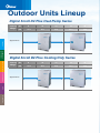
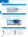
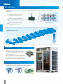
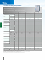
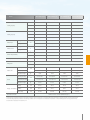
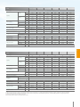
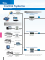
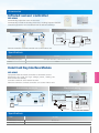
1
COMMERCIAL AIR CONDITIONERS R410A Digital Scroll VRF D4 Plus Series 50Hz D4 Plus/D4 Plus C Midea CAC (MCAC) As a key subsidiary of Midea Group, the Midea Central Air Conditioner (MCAC) business unit has emerged as a leading supplier of commercial solutions. Since 1999 MCAC has contributed to the R&D and innovation of technologically-based commercial solutions. Cooperation with leading global enterprises coupled with independent R&D has enabled MCAC to implement thousands of commercial air-conditioning projects worldwide. At present, MCAC is one of the globally leading product suppliers, underpinned by a mature marketing, sales, and project design framework. There are three production bases in Shunde, Chongqing and Hefei. MCAC Shunde: 38 product lines focusing on VRF (DC inverters and digital scroll products), split products, heat pump water heaters, and AHU/FCU. MCAC Chongqing: 14 product lines focusing on water cooled centrifugal/screw/scroll chillers, air cooled screw/scroll chillers, and AHU/FCU. MCAC Hefei: 11 product lines focusing on VRF, chillers, and heat pump water heaters. 2004 2014 2011 2007 2000 Year 1999 2001 2006 2010 2013 2014 Launched the All DC Inverter V5X globally 2013 Launched the super high efficiency centrifugal chiller with full falling film technology 2011 Launched the DC Inverter V4 Plus globally 2010 Built the 3rd manufacturing base in Hefei 2007 Won the first Midea centrifugal chiller project oversea 2006 Launched the first VSD centrifugal chiller 2004 Acquired MGRE entered the chiller industry 2001 Partnered with Copeland to develop the digital scroll VRF system 2000 Developed the first inverter VRF With Toshiba 1999 Entered the CAC field Outdoor Units Lineup Digital Scroll D4 Plus Heat Pump Series Capacity Range HP 8 10 12 14 16 kW 25.2 28.0 33.5 40.0 45.0 Features Appearance Outdoor unit specifications Digital Scroll D4 Plus Cooling Only Series Indoor units lineup Capacity Range HP 8 10 12 14 16 kW 25.2 28.0 33.5 40.0 45.0 Control systems Appearance HRV Branch Pipe Features Contents 05 Features 20 Indoor units lineup 77 HRV Control systems 80 Branch Pipe Indoor units lineup 51 Control systems Outdoor unit specifications 15 Outdoor unit specifications HRV Branch Pipe Features WIDE APPLICATION RANGE Wide Range of Outdoor Units The outdoor units capacity range from 8HP up to 64HP in 2HP increment. Maximum 64 indoor units with capacity up to 130% of total outdoor units can be connected in one refrigeration system. 8, 10,12HP 14, 16HP 18, 20, 22, 24, 26, 28, 30, 32HP Features 34,36, 38, 40, 42, 44, 46, 48HP 50, 52, 54, 56, 58, 60, 62, 64HP WIDE APPLICATION RANGE More Connectable Indoor Units The high number of connectable units is suitable for large buildings and projects. 70 65 60 55 50 45 40 35 30 25 20 15 13 16 20 23 26 29 33 36 39 43 46 50 53 56 59 63 64 64 64 64 64 64 64 64 64 64 64 64 64 10 5 05 64HP 62HP 60HP 58HP 56HP 54HP 52HP 50HP 48HP 46HP 44HP 42HP 40HP 38HP 36HP 34HP 32HP 30HP 28HP 26HP 24HP 22HP 20HP 18HP 16HP 14HP 12HP 10HP 8HP 0 Wide Operation Range COOLING MODE -15°C 54°C Outdoor Temperature HEATING MODE -15°C -1 0 0 10 20 30 40 Features -2 0 24°C Outdoor Temperature 50 Outdoor temp. °C(D.B.) No matter in extremely cold winter when outdoor temperature down to as low as -15°C or in hot summer when temperature is up to 54°C, the D4 Plus series system will keep stable operation. Long Piping Length The solution supports an incredible piping length of 1,000m and level difference of 110m, making it perfect for large projects. Total piping length*1 (Actual) Piping length 1000m Actual length 175m Equivalent length 200m Longest piping (L) Piping (The farthest IDU from the first Indoor unit branch)equivalent length Level difference between IDU~IDU 30m Level difference between IDU~ODU 110m 90m Longest piping actual length 175m Permitted value Level difference Level difference between IDU~ODU Outdoor unit up 70m Outdoor unit down 110m 30m Level difference between IDU~IDU *1 Total pipe length is equal to two times 40m/90m*2 pipe length plus pipe length. *2 When the farthest pipe length is more than 40m. It needs to meet the specific conditions according to the installation part of the technical manual. The first indoor unit branch Extra High Static Pressure – Max. 40Pa and Air Volume Increased by 10% High-static pressure propeller and optimized fan guard can adapt to various installation environments. 40 Pa Midea now offers up to 40 Pa* external static pressure units for customized applications. A standard 0-20Pa function is equipped by default. *You need to consult Midea if you require over 40Pa. 06 HIGHER RELIABILITY Duty Cycling In one combination, any outdoor unit can run as the master outdoor unit to equalize the service life of all units. DIG FIX DIG FIX DIG FIX Features Back-up Function In a multiple system, when the master unit failed, any single unit can be set as the master unit, then the remaining units can keep on working. This can be set on main board by DIP switch at site. DIG FIX DIG DIG FIX FIX When the slave 1 failed and came into standby state, the left module still work. High efficiency oil return technology Four stages oil control technology ensure every outdoor’s and compressor’s oil always keep in the safe level, completely avoid being oil shortage. 1st stage: compressor internal oil separate. 2nd stage: high efficiency oil separator. 3rd stage: oil balance technology between compressors. To condenser 4th stage: system oil return program. Oil separator 2nd stage Oil separator 2nd stage Refrigerant oil Compressor 1st stage Compressor 1st stage From evaporator Oil return program 4th stage Oil balance 3rd stage Indoor Unit Quantity Monitoring ENC3 S12 ON Quantity setting switch 07 The quantity of indoor units should be exactly set on the outdoor main board, once some indoor units miscommunicate with outdoor units during system running, the outdoor units will stop and display the fault code “H7”. This can prevent compressor from liquid hammer caused by dropped indoor units with EXV unclosed. HIGH EFFICIENCY The D4 PLUS Series with high efficient digital scroll compressor, DC motor and high efficient heat exchanger, achieve the world’s Top Class energy efficiency. The cooling EER up to 4.29 and the heating COP up to 4.6 in the 8HP category. High COP/EER Values COP EER 4.6 4.45 10HP 12HP 4.29 4.45 14HP 3.94 4.4 16HP 8HP 3.72 3.66 10HP 12HP 3.65 14HP Features 8HP 4.4 16HP High Efficient Heat Exchanger Original design Relative windage resistance New design Windage& air flow 0.8 0.6 0.4 Original design Reduce 28% 0.2 New design 0 High efficiency inner-threaded pipe, enhance heat transfer. Relative windage resistance 0 200 400 600 800 1000 Re Frost contrast 0.8 Reduce 30% Original design 0.6 0.4 New design 0.2 0 0 0.2 0.4 0.6 0.8 1 Relative frosting rate Hydrophilic film fins + inner-threaded pipes The new designed window fins enlarge the heat-exchanging area , decrease the air resistance, save more power and enhance heat exchange performance. Hydrophilic film fins and inner-threaded copper pipes optimize heat exchange efficiency. Original design Gas Liquid New design Gas Gas Liquid Gas Gas-Liquid Liquid Liquid Common Design Sub-cooling Technology Increase the hot liquid rate in the condenser Improve the heat-exchange efficiency Innovative designed high efficiency heat exchanger, which can reach up to 12oC subcooling degree, reduces the system resistance and improves reliability. When the outdoor temperature is 35oC, the refrigerant can be cooled down to 37.1oC, thus achieving high heat-exchanging efficiency with only 2.1oC temperature difference. 08 ENHANCED COMFORT Quick Warm-up & Cool-down Design and Less Temperature Fluctuation By utilizing the benefits of the digital compressor, the system can reach full load quickly and shorten the warm-up and cool-down times to provide an immediate and comfortable air solution. Less temperature fluctuation will create a better living environment. Temp. 1 2 Cooling operation Digital Non-digital Features Time Fluctuation of room temperature Night Silent Operation Mode Midea's Night Silent Mode feature which is easily set on the main board allows the unit to be set to varies time options during Non Peak and Peak operation time optimizing the units noise output. Extra silent operation mode can reduce sound level further, minimum 46.8dB (A). Night silent operation will be activated X hours after the peak temperature during daytime, and it will go back to normal operation after Y hours. Noise dB Load % Capacity % 0RGHOĺ;KRXUV<KRXUV0RGHOĺ;KRXUV<KRXUV 0RGHOĺ;KRXUV<KRXUV0RGHOĺ;KRXUV<KRXUV Peak value of ambient temp. 100 50 10hrs 8hrs Night silent Mode noisc Max.-10dB(10Hp) Start 08:00 14:00 Notes: This function can be activated by setting at site. 22:00 Temperature(load) curve shown in the graph is just an example. Intelligent Defrost Extend the Comfortable Time defrost 09 End 08:00 EASIER INSTALLATION AND SERVICE Compact Design for Effective Use of Space Easy to transport Compact size and light weight design minimizes the installation footprint, reduces the installation floor load, and is easier for transportation. For some projects the units can even be transported through the elevator or forklift, reduce access problem at the jobsite. Features Easy Maintainence Checking window on electric control box for convenient spot checking and status enquiry. Self-diagnosis function helps service engineers locate faults quickly and easily. Compressor is located near the door, which simplifies checks and enables valve or compressor parts to be replaced easily. Simple Signal Line Connection Installation is easier as communication wiring can be shared by indoor & outdoor units . It's easy for the user to retrofit the existing system with a centralized control by simply connecting to the outdoor units. P Q E XY E PQ E X Y E PQ E PQE & XYE: only one set of PQE signal wires can achieve communication among indoor units, outdoor units and the network. Reversible communication, central controller can be connected from indoor side or outdoor side as you wish. PQ E P Q E Wireless and wired controller can query and modify each indoor unit's address. 10 Auto Addressing Outdoor unit can distribute address for each indoor units automatically. Wireless controller and wired controller can enquire and modify each indoor units’ address. Various locking modes Features Various locking modes enhance convenience for users. In VIP priority or vote priority mode, the address of the VIP unit should be set as 63, if there is no 63 unit, it will respond to vote priority. ,ĞĂƟŶŐ priority mode (default) ŽŽůŝŶŐ priority mode VIP priority or vote priority KŶůLJƌĞƐƉŽŶĚ ƚŚĞŚĞĂƟŶŐ mode KŶůLJƌĞƐƉŽŶĚ ƚŚĞĐŽŽůŝŶŐ mode Integrated Solution for Control and Management Intelligent Manager of Midea, designed specifically to control VRF systems, is based around a centralized format and dedicated to the complete control and monitoring of all the system’s functions. It can be used as a flexible multi-purpose system and applied to a variety of needs, according to the scale, purpose and control method of each building. 11 ADVANCED TECHNOLOGIES Digital Scroll Compressor The digital scroll compressor utilizes axial compliant sealing technology to precisely adjust the axial motion range of the stator scroll pan. And there is an additional connecting by-pass between the suction inlet and the pressure bore at the floating sealing point of axial stator. PWM valve Provides 40 million times the average service life of PWM solenoid valves, making sure the long life of compressor. Discharge Fixed Scroll Suction Features Guarantees high efficiency by applying axial-compliant sealing technology. Orbiting Scroll Inverter EMC Regulation Digital Scroll System Ampere Provides 10% to 100% stepless capacity output to precisely control room temperature. Less electromagnetic interference, no EMC problem. 5th 7th 11th 13th 17th 19th 0 1 2 3 4 5 EMW Operation Principle of Digital Scroll Compressor When the PWM solenoid valve is open, the pressure in the pressure bore is released. The pressure in the compression bore is higher than that top of the stator, then the stator axis of the compressor will move upward a little. So high pressure bore and low pressure inlet is connected and the unloading is achieved. When the PWM solenoid valve is closed, two stators engage to achieve an airtight state and loading functionality. The compressor can adjust the ratio of ONs to OFFs freely to control the refrigerant output of the compressor. Low Pressure Design for Compressor Motor High reliability in high ambient temperatures is guaranteed by the low pressure design of the compressor motor. Ŷ(IIHFWLYHO\FRROVWKHFRPSUHVVRUPRWRUE\ suction gas. Discharge Suction Ŷ&UHDWHVVWURQJHUUHVLVWDQFHWRWKHFRPSUHVVRU liquid hammer. Compressor motor Ŷ3URYLGHVVWURQJUHOLDELOLW\LQKLJKDPELHQW temperatures. 12 DC Fan Motor According to the running load and pressure, it controls the speed of DC fan to achieve the min. power consumption. 100 Used across entire range of models (from 8 to 64 HP). EFFICIENCY (%) 80 Efficiency improvement up to 45% especially at low speed. Wide speed adjustment with 18 steps vector control. DC motor 60 Increased by 45% 40 20 200 1000 MOTOR SPEED (RPM) Features 18 steps vector control High Low Fan Grille Optimized fan blade shape with new air outlet grille enhanced air volume which greatly improves fan performance and decreases noise. Also, a higher external static pressure has been achieved up to 40 Pa.(0-20Pa is standard, 20~40Pa should be customized.) New Profile Fan Blade A new blade with sharp edges and a slight curve increases the airflow rate and lowers vibration and airflow resistance. 13 Recommended Combination Maximum N° of connectable Outdoor unit combination Model N°of outdoor N°of units compressors Capacity kW indoor units 8HP 10HP 12HP 14HP 16HP Heating 13 25.2 27 16 28 31.5 20 33.5 37.5 23 40 45 26 45 50 1 29 53.2 58.5 33 56 63 36 61.5 69 39 68 76.5 43 73 81.5 46 80 90 1 50 85 95 2 53 90 100 56 96 108 1 59 101 113 1 63 106.5 119 1 64 113 126.5 64 120 135 8HP 1 2 1 10HP 1 2 12HP 1 2 14HP 1 3 16HP 1 3 18HP 2 4 20HP 2 4 2 22HP 2 4 1 24HP 2 5 1 26HP 2 5 1 28HP 2 6 2 30HP 2 6 1 32HP 2 6 34HP 3 7 2 36HP 3 7 2 38hp 3 7 1 40HP 3 8 1 42HP 3 9 3 44HP 3 9 2 1 64 125 140 46HP 3 9 1 2 64 130 145 48HP 3 9 3 64 135 150 50HP 4 10 1 2 64 143.2 158.5 52HP 4 10 2 2 64 146 163 54HP 4 10 1 2 64 151.5 169 56HP 4 11 1 1 2 64 158 176.5 58HP 4 12 3 1 64 165 185 60HP 4 12 2 2 64 170 190 62HP 4 12 1 3 64 175 195 64HP 4 12 4 64 180 200 1 1 1 1 1 1 1 1 1 1 1 1 1 Features Cooling Notes: Capacities are based on the following conditions: Cooling: Indoor temperature 27oC (80.6oF) DB/19oC (66.2oF) WB; Outdoor temperature 35oC (95oF) DB/24oC (75.2oF) WB Heating: Indoor temperature 20oC (68oF) DB/15oC (59oF) WB; Outdoor temperature 7oC (44.6oF) DB/6oC (42.8oF) WB Piping length: Interconnecting piping length is 7.5m, level difference is zero. The heating capacity is only available for heat pump series. 14 Outdoor Unit Specifications D4 Plus Heat Pump Series MDV-D252(8)W/RN1-B MDV-D280(10)W/RN1-B MDV-D335(12)W/RN1-B MDV-D252(8)W/RN1-B Model Power supply Capacity Cooling Power input EER Capacity Heating Power input Outdoor unit specifications COP Connectable indoor unit Total capacity Pipe connections 380-415/3/50 380-415/3/50 kW 25.2 28.0 33.5 RT 7.2 8.0 9.5 kW 5.87 7.11 9.15 3.66 kW/kW 4.29 3.94 kW 27.0 31.5 37.5 RT 7.7 8.9 10.7 kW 5.87 7.08 8.52 kW/kW 4.60 4.45 4.40 % 50-130 50-130 50-130 13 16 20 dB(A) 57 57 58 Liquid pipe mm 9.5 9.5 12.7 Gas pipe mm 22.2 22.2 25.4 Gas balance pipe mm Type Quantity Fan motor – DC – DC 1 1 1 m3/h 11700 11700 11700 Motor output W 425 425 490 Pa 0-20 (default) 0-20 (default) 0-20 (default) Pa 20-40 (customized) 20-40 (customized) 20-40 (customized) 1 1 1 kW 16.85 16.85 16.85 W 5.75 5.75 5.75 POE POE POE ml initial 1893; refill 1774 initial 1893; refill 1774 initial 1893; refill 1774 1 1 1 kW 13.92 13.92 16.2 Quantity Capacity Input Oil type Oil charge Quantity Capacity Fixed scroll compressor – DC Air flow rate ESP Digital scroll compressor MDV-D335(12)W/RN1-B 380-415/3/50 Max. quantity Sound pressure level MDV-D280(10)W/RN1-B V/Ph/Hz Input W 4.61 4.61 5.2 POE POE POE initial 1656; refill 1538 initial 1656; refill 1538 initial 1685; refill 1567 R410A R410A R410A kg 9 9 10 MPa 4.4/2.6 4.4/2.6 4.4/2.6 Oil type Oil charge ml Type Refrigerant Factory charge Design pressure (High/Low) Net dimension (W×H×D) mm 960×1615×765 960×1615×765 960×1615×765 Packing dimension (W×H×D) mm 1025×1790×830 1025×1790×830 1025×1790×830 kg 240 240 242 Net weight Gross weight Operating temperature range kg 255 255 257 Cooling °C -15~54 -15~54 -15~54 Heating °C -15~24 -15~24 -15~24 Notes: Capacities are based on the following conditions: Cooling: Indoor temperature 27oC DB/19oC WB; Outdoor temperature 35oC DB/24oCWB. Heating: Indoor temperature 20oC DB/15oC WB; Outdoor temperature 7oC DB/6oCWB. Piping length: Interconnecting piping length is 7.5m, level difference is zero. Sound values are measured in a semi-anechoic room, at a position 1m in front of the unit and 1.3m above the floor. Conversion Formula: RT=kW×0.284; kcal/h= kW×860; Btu/h= kW×3412; CFM=m3/h×0.588. 15 D4 Plus Heat Pump Series MDV-D400(14)W/RN1-B MDV-D450(16)W/RN1-B Model Power supply V/Ph/Hz Capacity Cooling Power input EER Capacity Heating Power input COP Total capacity Pipe connections 40.0 45.0 RT 11.4 12.8 kW 10.75 12.33 3.72 3.65 kW/kW kW 45.0 50.0 RT 12.8 14.2 kW 10.11 11.36 kW/kW % 50-130 23 26 61 Liquid pipe mm 12.7 12.7 Gas pipe mm 25.4 28.6 Gas balance pipe mm – – DC+AC DC+AC 2 2 Air flow rate 3 m /h 15600 15600 Motor output W 420/380 420/380 ESP Pa 0-20 (default) 0-20 (default) Pa 20-40 (customized) 20-40 (customized) 1 1 kW 16.85 16.85 W 5.75 5.75 POE POE ml initial 1893; refill 1774 initial 1893; refill 1774 2 2 kW 16.2×2 16.2×2 W 5.2×2 5.2×2 Quantity Capacity Input Oil type Oil charge Quantity Capacity Fixed scroll compressor 4.40 50-130 60 Quantity Digital scrollcompressor 4.45 dB(A) Type Fan motor 380-415/3/50 kW Max. quantity Sound pressure level MDV-D450(16)W/RN1-B 380-415/3/50 Input Oil type Oil charge ml Type Refrigerant Factory charge POE POE initial 1685×2; refill 1567×2 initial 1685×2; refill 1567×2 R410A R410A kg 14 14 Design pressure (High/Low) MPa 4.4/2.6 4.4/2.6 Net dimension (W×H×D) mm 1250×1615×765 1250×1615×765 Packing dimension (W×H×D) mm 1305×1790×820 1305×1790×820 Net weight kg 330 330 Gross weight kg 345 345 Cooling °C -15~54 -15~54 Heating °C -15~24 -15~24 Operating temperature range Outdoor unit specifications Connectable indoor unit MDV-D400(14)W/RN1-B Notes: Capacities are based on the following conditions: Cooling: Indoor temperature 27oC DB/19oC WB; Outdoor temperature 35oC DB/24oCWB. Heating: Indoor temperature 20oC DB/15oC WB; Outdoor temperature 7oC DB/6oCWB. Piping length: Interconnecting piping length is 7.5m, level difference is zero. Sound values are measured in a semi-anechoic room, at a position 1m in front of the unit and 1.3m above the floor. Conversion Formula: RT=kW×0.284; kcal/h= kW×860; Btu/h= kW×3412; CFM=m3/h×0.588. 16 D4 Plus Cooling Only Series MDVC-D252(8)W/RN1-B MDVC-D280(10)W/RN1-B MDVC-D335(12)W/RN1-B Model MDVC-D252(8)W/RN1-B Power supply MDVC-D280(10)W/RN1-B MDVC-D335(12)W/RN1-B V/Ph/Hz 380-415/3/50 380-415/3/50 380-415/3/50 kW 25.2 28.0 33.5 Capacity RT 7.2 8.0 9.5 kW 5.87 7.11 9.15 kW/kW 4.29 3.94 3.66 % 50-130 50-130 50-130 13 16 20 57 57 58 Cooling Power input EER Total capacity Connectable indoor unit Max. quantity Sound pressure level Outdoor unit specifications Pipe connections dB(A) Liquid pipe mm 9.5 9.5 12.7 Gas pipe mm 22.2 22.2 25.4 Gas balance pipe mm – – – Type DC Quantity Air flow rate Fan motor Motor output m3/h DC DC 1 1 1 11700 11700 11700 W 425 425 490 Pa 0-20 (default) 0-20 (default) 0-20 (default) Pa 20-40 (customized) 20-40 (customized) 20-40 (customized) 1 1 1 16.85 16.85 16.85 ESP Quantity Capacity Digital scroll compressor Input kW W 5.75 5.75 5.75 POE POE POE ml initial 1893; refill 1774 initial 1893; refill 1774 initial 1893; refill 1774 1 1 1 Capacity kW 13.92 13.92 16.2 Input W Oil type Oil charge Quantity Fixed scroll compressor Oil type Oil charge ml Type 4.61 4.61 5.2 POE POE POE initial 1656; refill 1538 initial 1656; refill 1538 initial 1685; refill 1567 R410A R410A R410A kg 9 9 10 Design pressure (High/Low) MPa 4.4/2.6 4.4/2.6 4.4/2.6 Net dimension (W×H×D) mm 960×1615×765 960×1615×765 960×1615×765 Packing dimension (W×H×D) mm 1025×1790×830 1025×1790×830 1025×1790×830 Net weight kg 240 240 242 Gross weight kg 255 255 Refrigerant Factory charge Operating temperature Cooling °C -15~54 -15~54 range Notes: Capacities are based on the following conditions: Cooling: Indoor temperature 27oC DB/19oC WB; Outdoor temperature 35oC DB/24oCWB. Piping length: Interconnecting piping length is 7.5m, level difference is zero. Sound values are measured in a semi-anechoic room, at a position 1m in front of the unit and 1.3m above the floor. Conversion Formula: RT=kW×0.284; kcal/h= kW×860; Btu/h= kW×3412; CFM=m3/h×0.588. 17 257 -15~54 D4 Plus Cooling Only Series MDVC-D400(14)W/RN1-B MDVC-D450(16)W/RN1-B Model MDVC-D400(14)W/RN1-B Power supply MDVC-D450(16)W/RN1-B V/Ph/Hz 380-415/3/50 380-415/3/50 kW 40.0 45.0 RT 11.4 12.8 Capacity Cooling Power input kW 10.75 12.33 kW/kW 3.72 3.65 % 50-130 50-130 23 26 dB(A) 60 61 Liquid pipe mm 12.7 12.7 Gas pipe mm 25.4 28.6 Gas balance pipe mm – – DC+AC DC+AC 2 2 EER Total capacity Connectable indoor unit Max. quantity Sound pressure level Type Quantity Air flow rate m3/h 15600 15600 Motor output W 420/380 420/380 Pa 0-20 (default) 0-20 (default) Pa 20-40 (customized) 20-40 (customized) 1 1 16.85 16.85 Fan motor Outdoor unit specifications Pipe connections ESP Quantity Capacity kW Input W Digital scroll compressor Oil type Oil charge ml Quantity Fixed scroll compressor 5.75 5.75 POE POE initial 1893; refill 1774 initial 1893; refill 1774 2 2 Capacity kW 16.2×2 16.2×2 Input W 5.2×2 5.2×2 POE POE initial 1685×2; refill 1567×2 initial 1685×2; refill 1567×2 R410A R410A 14 14 Oil type Oil charge ml Type Refrigerant Factory charge kg Design pressure (High/Low) MPa 4.4/2.6 4.4/2.6 Net dimension (W×H×D) mm 1250×1615×765 1250×1615×765 Packing dimension (W×H×D) mm 1305×1790×820 1305×1790×820 Net weight kg 330 330 Gross weight kg 345 345 °C -15~54 -15~54 Operating temperature range Cooling Notes: Capacities are based on the following conditions: Cooling: Indoor temperature 27oC DB/19oC WB; Outdoor temperature 35oC DB/24oCWB. Piping length: Interconnecting piping length is 7.5m, level difference is zero. Sound values are measured in a semi-anechoic room, at a position 1m in front of the unit and 1.3m above the floor. Conversion Formula: RT=kW×0.284; kcal/h= kW×860; Btu/h= kW×3412; CFM=m3/h×0.588. 18 Dimension Body Dimension Unit: mm 1615 14/16 HP 1615 8/10/12 HP 765 1250 765 960 Outdoor unit specifications Gas balance valve (Connect for parallel connection units) Gauge point (For refrigerant recharge) Liquid pipe Gas pipe HP 8 10 12 14 16 A 130 130 130 165 165 B 160 160 160 195 195 C 195 195 195 230 230 D 170 170 170 170 170 E 200 200 200 200 200 Liquid pipe 2'ĭ 2'ĭ 2'ĭ 2'ĭ 2'ĭ Gas pipe 2'ĭ 2'ĭ 2'ĭ 2'ĭ 2'ĭ SIZE D E A B C R: Pipe Connection R Section View Installation Dimension Unit: mm Outdoor Unit Screw Bolt Position B A ĭ([SDQVLRQEROW Rubber shocking proof mat 200 D C Solid ground or roofing HP Concrete basement h=200 15×23 long u-shape hole 8/10/12 SIZE A B C D Notes: 1. Ensure that the outdoor unit is installed in a dry, well-ventilated place. 2. Ensure that the noise and exhaust ventilation of the outdoor unit do not affect the neighbors of the property owner or the surrounding ventilation. 3. Ensure that the outdoor unit is installed in a well-ventilated place as close as possible to the indoor unit. 4. Ensure that the outdoor unit is installed in a cool place without direct sunshine exposure or direct radiation of high-temp heat source. 5. Do not install the outdoor unit in a dirty or severely polluted area to avoid blocking the heat exchanger in the outdoor unit. 6. Do not install the outdoor unit in a place with oil pollution or full of harmful gases such as sulfurous gas. 7. Do not install the outdoor unit in a place surrounded by salty air. (Except for the models with corrosion-resistant function.) 19 830 960 736 765 14/16 1120 1250 736 765 Indoor Units Lineup One-way Cassette Indoor units lineup Two-way Cassette Compact Four-way Cassette Four-way Cassette Low Static Pressure Duct Concealed Duct Unit (A5 Type) High Static Pressure Duct Ceiling & Floor Wall-mounted Floor Standing Console Fresh Air Processing Unit 20 Type kW 1.8 2.2 2.8 One-way Cassette Two-way Cassette Compact Four-way Cassette Four-way Cassette Low Static Pressure Duct Concealed Duct Unit (A5 Type) Indoor units lineup High Static Pressure Duct Ceiling & Floor Wall-mounted Floor Standing Console Fresh Air Processing Unit More than 100 models are available to meet varied customer requirements. 3.6 4.5 5.6 7.1 8.0 9.0 10.0 11.2 12.5 14.0 16.0 20.0 25.0 28.0 40.0 45.0 56.0 Indoor units lineup One-way Cassette LED Auto Restart Fresh Air Auto Addressing Cleanable Panel Follow Me Anti-Cold Air Function LED Display Built-in Drain Pump DISPLAY Only 153mm thickness Auto swing Compact design,ultra slim body with a minimum thickness of 153mm for model 18-36,especially suitable for narrow ceiling , such as in lobbies and small meeting rooms. Auto swing mechanism guarantees even airflow distribution and a better room temperature balance. Indoor units lineup 153mm UItra Thin Single-flow design suits corner installation Standard built-in drain pump with 750mm pump head. 750mm Fresh air, improved air quality Reserved fresh air intake port for high quality air creates a comfortable and healthy environment. Special enzyme sterilization and filtering technologies filter bacteria, smog, and pollen. Provide a clean, healthy and natural air supply. Acetaldehyde Acetic acid Formol NH3 MDV-D18Q1 /N1-D Model MDV-D22Q1 /N1-D MDV-D28Q1 /N1-D Power supply MDV-D36Q1 /N1-D MDV-D45Q1 /N1-C MDV-D56Q1 /N1-C 1-phase,220-240V,50Hz kW 1.8 2.2 2.8 3.6 4.5 5.6 kcal/h 1500 1900 2400 3100 3900 4800 Btu/h 6100 7500 9600 12300 15400 19100 kW 2.2 2.6 3.2 4 5 6.3 kcal/h 1900 2200 2800 3400 4300 5400 Btu/h 7500 8900 10900 13600 17100 21500 41 41 41 41 80 85 Heating 41 41 41 41 80 85 Cooling 0.24 0.24 0.25 0.25 0.37 0.39 0.24 0.24 0.25 0.25 0.37 0.39 Cooling capacity Heating capacity Cooling Rated input W Rated current A Heating 3 523/404/275 523/404/275 573/456/315 573/456/315 704/630/503 860/810/702 CFM 308/238/162 308/238/162 337/268/185 337/268/185 414/370/296 506/476/413 Sound pressure level(H/M/L) dB(A) 37/34/30 38/34/30 39/37/34 40/38/34 41/39/35 42/40/36 Type R410A Control method EXV Refrigerant Net dim.(W×H×D) 1054×169×425 1147×200×640 1155×245×490 1380×265×775 mm Indoor Unit Gross dim.(W×H×D) Net/Gross kg Net dim.(W×H×D) 12.5/16 13/16.5 31.5/37.2 1180×36.5×465 1180×36.5×465 1425×10×755 1232×107×517 1232×107×517 1500×110×870 mm Panel Gross dim.(W×H×D) kg 3.5/5.2 3.5/5.2 L(flare) mm ĭ6.35 Ɏ6.35 Ɏ6.35 Ɏ9.53 Piping connections G(flare) mm ĭ12.7 Ɏ12.7 Ɏ12.7 Ɏ mm OD Ɏ25 OD Ɏ25 Net/Gross Drain piping Standard Controller 9/12 OD Ɏ25 Wireless remote controller RM05/BG(T)E-A/E) Notes: 1. Nominal cooling capacities are based on the following conditions: return air temperature. : 27°CDB,19°CWB,outdoor temperature.:35°CDB, equivalent ref. Piping: 8m(horizontal) 2. Nominal heating capacities are based on the following conditions: return air temperature.: 20°CDB,outdoor temperature.: 7°CDB, 6°CWB,equivalent ref. Piping: 8m(horizontal) 3. Sound level is measured at 1.4m below the unit. Indoor units lineup m /h Airflow rate(H/M/L) Two-way Cassette LED Auto Restart Fresh Air Auto Addressing Cleanable Panel Follow Me Anti-Cold Air Function LED Display Built-in Drain Pump DISPLAY Indoor units lineup Quiet operation High airflow Optimized airflow duct with low resistance greatly reduces noise, minimum down to 24dB(A). High airflow for high ceiling application guarantees comfort in large space. It makes every person in the room get even distribution of airflow and temperature. Stylish design and slim body Thanks to the stylish appearance and slim body, the unit suits any room's decor and ambience. At only 300mm high, the unit requires only a small suspended ceiling space. Installation has no height limitations, which makes overall design features much more flexible. 300mm 305mm Standard built-in drain pump with 750mm pump head (higher pump head can be customized). 750mm Flat-type suction grille design greatly simplifies maintenance work. Model MDV-D22Q2/N1 MDV-D28Q2/N1 Power supply MDV-D36Q2/N1 MDV-D45Q2/N1 MDV-D56Q2/N1 MDV-D71Q2/N1 1-phase, 220-240V, 50Hz Cooling capacity Heating capacity kW 2.2 2.8 3.6 4.5 5.6 7.1 kcal/h 1,900 2,400 3,100 3,900 4,800 6,100 Btu/h 7,500 9,600 12,300 15,400 19,100 24,200 kW 2.6 3.2 4.0 5.0 6.3 8.0 kcal/h 2,200 2,800 3,400 4,300 5,400 6,900 Btu/h 8,900 10,900 13,600 17,100 21,500 27,300 57 57 60 92 108 154 57 57 60 92 108 154 0.35 0.45 0.45 0.55 0.55 0.75 0.35 0.45 0.45 0.55 0.55 0.75 m3/h 654/530/410 654/530/410 725/591/458 850/670/550 980/800/670 1,200/1,000/770 CFM 385/312/241 385/312/241 427/348/270 500/394/324 577/471/394 706/589/453 dB(A) 33/29/24 36/32/29 36/32/29 39/35/30 39/35/30 44/40/34 Cooling Power input W Heating Cooling A Rated current Heating Airflow rate(H/M/L) Refrigerant Type R410A Control method EXV 1,172×299×591 1,172×299×591 1,172×299×591 1,172×299×591 1,172×299×591 1,172×299×591 1,355×400×675 1,355×400×675 1,355×400×675 1,355×400×675 1,355×400×675 1,355×400×675 34/42.5 34/42.5 34/42.5 36/44.5 36/44.5 36/44.5 1,430×53×680 1,430×53×680 1,430×53×680 1,430×53×680 1,430×53×680 1,430×53×680 1,525×130×765 1,525×130×765 1,525×130×765 1,525×130×765 1,525×130×765 1,525×130×765 kg 10.5/15 10.5/15 10.5/15 10.5/15 10.5/15 10.5/15 L(flare) mm ĭ ĭ ĭ ĭ ĭ ĭ G(flare) mm ĭ ĭ ĭ ĭ ĭ ĭ Drain piping mm 2'Ɏ 2'Ɏ 2'Ɏ 2'Ɏ 2'Ɏ 2'Ɏ Net dim.(W×H×D) mm Body Gross dim.(W×H×D) Net/gross kg Net dim.(W×H×D) mm Panel Gross dim.(W×H×D) Net/gross Piping connections Standard Controller - Wireless remote controller(RM05/BG(T)E-A) Notes: 1. Nominal cooling capacities are based on the following conditions: return air temperature. : 27°CDB,19°CWB,outdoor temperature.:35°CDB, equivalent ref. Piping: 8m(horizontal) 2. Nominal heating capacities are based on the following conditions: return air temperature.: 20°CDB,outdoor temperature.: 7°CDB, 6°CWB,equivalent ref. Piping: 8m(horizontal) 3. Sound level is measured at 1.4m below the unit. Indoor units lineup Sound pressure level(H/M/L) Compact Four-way Cassette Auto Restart Fresh Air Auto Addressing Cleanable Panel Follow Me Anti-Cold Air Function Built-in Drain Pump LED LED Display DISPLAY Super High Air Flow Compact design, easy installation Fresh air intake 570m m mm 0 57 Indoor units lineup Extremely compact casing suits any room's decor and requires little space for installation on a low ceiling. Due to the compact body and light weight, all models can be installed without a hoist. Fresh air can enter through the cassette unit so you can enjoy even fresher air in your room. Quiet operation, gentle air supply Sub duct Diffuser 3-D spiral fan blade Streamline plate ensures quiet operation. Advanced 3-D spiral fan design reduces air resistance and operation noise. Sub duct enables you to use the same air conditioner unit to cool an additional smaller space nearby. 360°Airflow outlet High-lift drain pump 360° air outlet provides strong air flow circulation to cool or heat every corner of a room and evenly distribute temperature. 500mm Drain pump with a 500mm pump head is fitted as standard; maximum 600mm pump head is available. MDV-D22Q4/N1-A3 Model MDV-D28Q4/N1-A3 Power supply MDV-D36Q4/N1-A3 MDV-D45Q4/N1-A3 1-phase,220-240V,50Hz kW Cooling capacity Heating capacity 2.2 2.8 3.6 4.5 kcal/h 1900 2400 3100 3900 Btu/h 7500 9600 12300 15400 kW 2.4 3.2 4 5 kcal/h 2100 2700 3400 4300 Btu/h 8200 10900 13600 17100 50 50 56 56 50 50 56 56 0.22 0.22 0.25 0.25 0.22 0.22 0.25 0.25 m /h 522/414/313/238 522/414/313/238 610/521/409/314 610/521/409/314 CFM 307/244/184/140 307/244/184/140 359/307/241/185 359/307/241/185 dB(A) 35.8/33.4/23.4 35.8/33.4/23.4 41.5/35.6/28.8 41.5/35.6/28.8 Cooling Rated input W Heating Cooling Rated current A Heating 3 Airflow rate(SH/H/M/L) Type R410A Control method EXV Refrigerant Net dim.(W×H×D) 570×260×570 570×260×570 570×260×570 570×260×570 675×285×675 675×285×675 675×285×675 675×285×675 16/20 16/20 18/22 18/22 647×50×647 647×50×647 647×50×647 647×50×647 715×123×715 715×123×715 715×123×715 715×123×715 Indoor units lineup Sound pressure level(H/M/L) mm Indoor Unit Gross dim.(W×H×D) Net/Gross weight kg Net dim.(W×H×D) mm Panel Piping connections Standard Controller Gross dim.(W×H×D) Net/Gross weight kg 2.4/4.5 2.4/4.5 2.4/4.5 2.4/4.5 L(flare) mm ĭ6.35 Ɏ6.35 ĭ6.35 Ɏ6.35 G(flare) mm ĭ12.7 Ɏ12.7 ĭ12.7 Ɏ12.7 Drain piping mm OD Ɏ25 OD Ɏ25 OD Ɏ25 OD Ɏ25 Wireless remote controller (RM05/BG(T)E-A) Notes: 1. Nominal cooling capacities are based on the following conditions: return air temperature. : 27°CDB,19°CWB,outdoor temperature.:35°CDB, equivalent ref. Piping: 8m(horizontal) 2. Nominal heating capacities are based on the following conditions: return air temperature.: 20°CDB,outdoor temperature.: 7°CDB, 6°CWB,equivalent ref. Piping: 8m(horizontal) 3. Sound level is measured at 1.4m below the unit. Four-way Cassette Auto Restart Fresh Air Auto Addressing Cleanable Panel Follow Me Anti-Cold Air Function Built-in Drain Pump LED LED Display Super High Air Flow Quiet operation, gentle air supply Fresh air intake Ŷ Streamline plate ensures quiet operation. Ŷ Advanced 3-D spiral fan design reduces air resistance and operation noise. Diffuser Indoor units lineup Fresh air can enter through the cassette unit so you can enjoy even fresher air in your room. 3-D spiral fan blade Sub duct Easy troubleshooting By adding digital tube on the display board, Error Codes can be displayed directly for troubleshooting. Sub duct enables you to use the same air conditioner unit to cool an additional smaller space nearby. Four-way uniform airflow High-lift drain pump Drain pump can take condenser water up to 750mm, which simplifies installation of the drain piping system. 750mm Four air discharge ports provide strong air flow circulation to cool or heat every corner of a room and evenly distribute temperature. High airflow mode can maximize the conditioning effect in rooms that are over 3m high. Model MDV-D28Q4/N1-D MDV-D36Q4/N1-D Power supply 1-phase, 220-240V, 50Hz 3.6 4.5 5.6 7.1 kcal/h 2,400 3,100 3,900 4,800 6,100 Btu/h 9,600 12,300 15,400 19,100 24,200 kW 3.2 4.0 5.0 6.3 8.0 kcal/h 2,800 3,400 4,300 5,400 6,900 Btu/h 10,900 13,600 17,100 21,500 27,300 65 65 75 75 82 Heating 65 65 75 75 82 Cooling 0.4 0.4 0.4 0.4 0.5 Cooling Power input Rated current W A Heating Airflow rate(SH/H/M/L) Sound pressure level(H/M/L) 0.4 0.4 0.4 0.4 0.5 m3/h 1,187/847/766/640 1,187/847/766/640 1,121/864/755/658 1,121/864/755/658 1,385/1,157/955/749 CFM 699/498/450/376 699/498/450/376 660/508/444/387 660/508/444/387 815/680/562/440 dB(A) 42/38/35 42/38/35 42/38/35 42/38/35 45/42/39 Type Refrigerant mm Gross dim.(W×H×D) Net/gross Net dim.(W×H×D) kg mm EXV 904×230×840 904×230×840 904×230×840 904×230×840 904×230×840 955×260×955 955×260×955 955×260×955 955×260×955 955×260×955 24/28 24/28 26/30 26/30 26/30 950×54.5×950 950×54.5×950 950×54.5×950 950×54.5×950 950×54.5×950 1035×90×1035 1035×90×1035 1035×90×1035 1035×90×1035 1035×90×1035 kg 6/9 6/9 6/9 6/9 6/9 L(flare) mm ĭ ĭ ĭ ĭ ĭ G(flare) mm ĭ ĭ ĭ ĭ ĭ Drain piping mm 2'Ɏ 2'Ɏ 2'Ɏ 2'Ɏ 2'Ɏ Gross dim.(W×H×D) Net/gross connections R410A Control method Net dim.(W×H×D) Piping Standard Controller - Wireless remote controller(RM05/BG(T)E-A) MDV-D80Q4/N1-D MDV-D90Q4/N1-D kW 8.0 9.0 10.0 11.2 14.0 kcal/h 6,900 7,700 8,600 9,600 12,000 Btu/h 27,300 30,700 34,100 38,200 47,800 kW 9.0 10.0 11.1 12.5 15.0 kcal/h 7,700 8,600 9,500 10,800 12,900 Btu/h 30,700 34,100 37,900 42,700 51,200 97 160 160 160 170 Heating 97 160 160 160 170 Cooling 0.5 0.7 0.7 0.7 0.8 0.5 0.7 0.7 0.7 0.8 m3/h 1,431/1,236/973/729 1,758/1,540/1,300/1,120 1,758/1,540/1,300/1,120 1,758/1,540/1,300/1,120 1,843/1,800/1,500/1,280 CFM 842/727/572/429 1,035/906/765/659 1,035/906/765/659 1,035/906/765/659 1,085/1,059/883/753 dB(A) 45/42/39 48/45/43 48/45/43 48/45/43 50/47/44 Power supply Heating capacity Cooling W A Heating Airflow rate(SH/H/M/L) Sound pressure level(H/M/L) Type Refrigerant Net dim.(W×H×D) connections kg mm Gross dim.(W×H×D) EXV 904×230×840 904×300×840 904×300×840 904×300×840 904×300×840 955×260×955 955×330×955 955×330×955 955×330×955 955×330×955 26/30 32/37 32/37 32/37 32/37 950×54.5×950 950×54.5×950 950×54.5×950 950×54.5×950 950×54.5×950 1035×90×1035 1035x90x1035 1035×90×1035 1035×90×1035 1035×90×1035 kg 6/9 6/9 6/9 6/9 6/9 L(flare) mm ĭ ĭ ĭ ĭ ĭ G(flare) mm ĭ ĭ ĭ ĭ ĭ Drain piping mm 2'Ɏ 2'Ɏ 2'Ɏ 2'Ɏ 2'Ɏ Net/gross Piping mm Gross dim.(W×H×D) Net/gross Panel MDV-D140Q4/N1-D R410A Control method Net dim.(W×H×D) Body MDV-D112Q4/N1-D 1-phase, 220-240V, 50Hz Cooling capacity Rated current MDV-D100Q4/N1-D Standard Controller - Wireless remote controller(RM05/BG(T)E-A) Notes: 1. Nominal cooling capacities are based on the following conditions: return air temperature. : 27°CDB,19°CWB,outdoor temperature.:35°CDB, equivalent ref. Piping: 8m(horizontal) 2. Nominal heating capacities are based on the following conditions: return air temperature.: 20°CDB,outdoor temperature.: 7°CDB, 6°CWB,equivalent ref. Piping: 8m(horizontal) 3. Sound level is measured at 1.4m below the unit. Indoor units lineup Model Power input MDV-D71Q4/N1-D 2.8 Heating capacity Panel MDV-D56Q4/N1-D kW Cooling capacity Body MDV-D45Q4/N1-D Four-way Cassette - Silent Type Auto Restart Fresh Air Auto Addressing Cleanable Panel Follow Me Anti-Cold Air Function Built-in Drain Pump LED LED Display Super High Air Flow Lower operating sound The new designed fan blade, air deflector and the built-in throttling part make the noise reduced greatly. Indoor units lineup The former fan blade Optimized fan blade More reliable Ŷ The connection of drainage pan adopts foaming technology which can further improve the connection tightness. Ŷ Capacitor is isolated by a sheet metal box making it safer and even more reliable. Ŷ The high voltage and low voltage electricity wires are separated in electronic control box making the interference decreased greatly. Flexible air distribution type Ŷ 7 discharge patterns in 2 to 4 directions can be selected to suit the requirements of installation site or the shape of the room. Ŷ Duct connection is possible. Model MDV-D28Q4/N1-E MDV-D36Q4/N1-E Power supply Cooling capacity Heating capacity Power input Rated current Panel Piping connections MDV-D71Q4/N1-E kW 2.8 3.6 4.5 5.6 7.1 kcal/h 2,400 3,100 3,900 4,800 6,100 Btu/h 9,600 12,300 15,400 19,100 24,200 kW 3.2 4 5 6.3 8 kcal/h 2,800 3,400 4,300 5,400 6,900 Btu/h 10,900 13,600 17,100 21,500 27,300 W 80 80 88 88 88 Heating W 80 80 88 88 88 Cooling A 0.31 0.31 0.41 0.41 0.41 Heating A 0.31 0.31 0.41 0.41 0.41 m³/h 920/764/638//554 920/764/638//554 1090/905/740//651 1090/905/740//651 1140/950/767//663 CFM 541/450/375/326 541/450/375/326 641/532/435/383 641/532/435/383 670/560/451/390 dB(A) 32/31/30 32/31/30 36/34/33 36/34/33 38/36/35 23.7/28.9 23.7/28.9 Sound pressure level (H/M/L) Body MDV-D56Q4/N1-E Cooling Airflow rate (SH/H/M/L) Refrigerant MDV-D45Q4/N1-E 1-phase, 220-240V, 50Hz Type R410A Control method EXV 840×230×840 Net dim. (W×H×D) mm Gross dim. (W×H×D) mm Net/Gross weight kg Net dim. (W×H×D) mm 950×54.5×950 Gross dim. (W×H×D) mm 1035×90×1035 Net/Gross weight kg L (flare) mm ĭ G (flare) mm ĭ Drain piping mm 955×260×955 21.5/26.7 21.5/26.7 6/9 MDV-D90Q4/N1-E Cooling capacity Heating capacity Piping connections Standard controller 8.0 9.0 10.0 11.2 14.0 6,900 7,700 8,600 9,600 12,000 Btu/h 27,300 30,700 34,100 38,200 47,800 kW 9.0 10.0 11.1 12.5 16.0 kcal/h 7,700 8,600 9,500 10,800 13,800 Btu/h 30,700 34,100 37,900 42,700 54,600 W 110 140 165 165 176 Heating W 110 140 165 165 176 Cooling A 0.48 0.67 0.72 0.72 0.75 Heating A 0.48 0.67 0.72 0.72 0.75 Sound pressure level (H/M/L) Panel kW kcal/h Cooling Airflow rate (SH/H/M/L) Body MDV-D100Q4/N1-E MDV-D112Q4/N1-E MDV-D140Q4/N1-E 1-phase, 220-240V, 50Hz m³/h 1380/1200/1021/789 1598/1332/1129/908 1750/1651/1304/1127 1750/1651/1304/1127 1774/1658/1335/1130 CFM 812/706/600/464 940/784/664/534 1029/971/767/663 1029/971/767/663 1044/975/785/665 dB(A) 42/39/37 43/39/38 45/42/40 45/42/40 46/41/39 Type R410A Control method EXV 840×300×840 Net dim. (W×H×D) mm 840×230×840 Gross dim. (W×H×D) mm 955×260×955 Net/Gross weight kg 23.7/28.9 Net dim. (W×H×D) mm 950×54.5×950 Gross dim. (W×H×D) mm 1035×90×1035 Net/Gross weight kg 6/9 L (flare) mm ĭ G (flare) mm ĭ Drain piping mm 955×330×955 28.7/34.1 28.7/34.1 28.7/34.1 30.9/36.3 ĭ Wireless remote controller (RM05/BG(T)E-A) Notes: 1. Nominal cooling capacities are based on the following conditions: return air temperature. : 27°CDB,19°CWB,outdoor temperature.:35°CDB, equivalent ref. Piping: 8m(horizontal) 2. Nominal heating capacities are based on the following conditions: return air temperature.: 20°CDB,outdoor temperature.: 7°CDB, 6°CWB,equivalent ref. Piping: 8m(horizontal) 3. Sound level is measured at 1.4m below the unit. Indoor units lineup MDV-D80Q4/N1-E Power supply Refrigerant ĭ Wireless remote controller (RM05/BG(T)E-A) Model Rated current ĭ ĭ Standard controller Power input 23.7/28.9 Low Static Pressure Duct Auto Restart Anti-Cold Air Function Auto Addressing Wireless remote controller Follow Me Super High Air Flow Low sound level Utilizes the centrifugal type blower, provides a minimum Indoor units lineup noise level of 24dB (A), an excellent choice for hotels and other sound-sensitive places. V shape evaporator-good heat More Smooth airflow with lessfor turbulence exchanging Convenient for installation installation and maintenance V shape evaporator design enhances heat exchanging efficiency about 22%. The EXV is fixed inside the indoor unit. Compact design Options Min.5mm 750mm 210mm Ceiling ceiling Uniform 210mm in height, compact design for easy A drain pump with 750mm pumphead is an locate where space ceiling is limited, The whole body adopts fireproof plastic material, the minimum weight is 14kg. optional accessory. Model MDV-D18T3/N1-C MDV-D22T3/N1-C MDV-D28T3/N1-C MDV-D36T3/N1-C MDV-D45T3/N1-C MDV-D56T3/N1-C MDV-D71T3/N1-C Power supply Cooling capacity Heating capacity 220-240V~1Ph~50Hz kW 1.8 2.2 2.8 3.6 4.5 5.6 7.1 kcal/h 1500 1900 2400 3100 3900 4800 6100 Btu/h 6100 7500 9600 12300 15400 19100 24200 kW 2.2 2.6 3.2 4 5 6.3 8 kcal/h 1900 2200 2800 3400 4300 5400 6900 Btu/h 7500 8900 10900 13600 17100 21500 27300 59 59 59 65 105 105 130 59 59 59 65 105 105 130 0.31 0.31 0.31 0.36 0.36 0.36 0.5 0.31 0.31 0.31 0.36 0.36 Cooling Rated input W Heating Rated current Cooling A Heating m³/h 0.36 646(30pa) /617/551/441 606(30pa)/578/512/409 Airflow rate(SH/H/M/L) CFM External Static Pressure Sound pressure level ( H/M/L) Refrigerant type Indoor unit L(flare) Piping connections G(flare) Drain piping Standard Controller 380/363/324/260 473/485/406/358 710/624/571/477 Pa 10(10~30) 10(10~30) 10(10~30) 10(10~30) 10(10~30) 10(10~30) 10(10~30) dB(A) 35/27/24 35/27/24 35/27/24 38/32/28 39/32/29 39/32/29 41/33/30 R410A R410A R410A R410A R410A R410A R410A EXV EXV EXV EXV EXV EXV EXV Type Control type mm 740×210×470 740×210×470 740×210×470 740×210×470 960×210×470 960×210×470 1180×210×470 mm 910×230×510 910×230×510 910×230×510 910×230×510 1130×230×510 1130×230×510 1350×230×510 kg 14/17.5 14/17.5 14/17.5 14/17.5 17.5/22 17.5/22 21/26.5 mm Ɏ6.35 Ɏ6.35 Ɏ6.35 Ɏ6.35 Ɏ6.35 Ɏ9.53 Ɏ9.53 mm Ɏ12.7 Ɏ12.7 Ɏ12.7 Ɏ12.7 Ɏ12.7 Ɏ15.9 Ɏ15.9 mm Ɏ25 Ɏ25 Ɏ25 Ɏ25 Ɏ25 Ɏ25 Ɏ25 Indoor units lineup Dimension (W×H×D) Packing (W×H×D) Net(Gross) weight 357/340/301/241 803(pa)/824/690/609 0.5 1207(30pa) /1060/970/811 Wireless remote controller (RM05/BG(T)E-A) Notes: 1. Nominal cooling capacities are based on the following conditions: return air temperature. : 27°CDB,19°CWB,outdoor temperature.:35°CDB, equivalent ref. Piping: 8m(horizontal) 2. Nominal heating capacities are based on the following conditions: return air temperature.: 20°CDB,outdoor temperature.: 7°CDB, 6°CWB,equivalent ref. Piping: 8m(horizontal) 3. Sound level is measured at 1.4m below the air outlet. External static pressure is based on high speed indoor air flow. Concealed Duct Unit (A5 Type) Auto Restart Fresh Air Follow Me Anti-Cold Air Function Built-in Drain Pump Wired Controller Auto Addressing Super High Air Flow Connectable To Duct Compact size External static pressure Four speed fan motor (Super high speed is Min.5mm optional) Indoor units lineup 210mm or270mm or300mm Change the wiring connection from ‘SH’ to ‘H’ to change the ESP. Ceiling Only 210mm (15~71 models) or 270mm (80 to 112 models) or 300mm (140 model) in height. Convenient installation The EXV is fixed inside of the indoor unit. Standard filter is housed in an aluminum frame, which is removable from the bottom in the downward direction. Suction chamber is included as standard equipment. Fresh air hole, air inlet/outlet flange are standard for easy duct connection. A rear air inlet is standard and an inlet at the bottom is optional. Both use the same connectable duct. Air intake from back Air intake from below drain pump as standard 750mm ceiling Flexible control and easy maintenance Standard wired remote controller KJR-29B1/BK-E. The electrical control box can be removed 1m away from the unit for easy maintenance access. Customers need to request this service in advance for it is done at Midea CAC factory. Standard functional ports are included such as Remote On/Off Dry contact switch and Alarm signal output (220V). MDV-D22T2 /N1-DA5 Model Cooling capacity Heating capacity Rated current MDV-D45T2 /N1-DA5 MDV-D56T2 /N1-DA5 1-phase,220-240V,50Hz Power supply Rated input MDV-D36T2 /N1-DA5 MDV-D28T2 /N1-DA5 Cooling kW 2.2 2.8 3.6 4.5 5.6 kcal/h 1900 2400 3100 3900 4800 Btu/h 7500 9600 12300 15400 19100 kW 2.6 3.2 4 5 6.3 kcal/h 2200 2800 3400 4300 5400 Btu/h 8900 10900 13600 17100 21500 57 57 61 98 103 W Heating 57 57 61 98 103 Cooling 0.31 0.31 0.33 0.36 0.36 0.31 0.31 0.33 614(30pa)/597 /514/429 0.36 763(30pa)/811 /684/575 0.36 763(30pa)/811 /684/575 361/351/303/253 449/477/403/338 449/477/403/338 A Heating m 3/h Airflow rate(SH/H/M/L) 588(30pa)/538/456/375 CFM 346/317/268/221 ESP(external static pressure) Pa 10(10-30) 10(10-30) 10(10-30) 10(10-30) 10(10-30) Sound pressure level(H/M/L) dB(A) 36/35/32 37/35/32 38.6/37.5/33.8 39/37.9/34 39/37.9/34 Net dim.(W×H×D) Indoor Unit EXV mm Gross dim.(W×H×D) NetGross 740×210×500 740×210×500 740×210×500 960×210×500 960×210×500 870×285×525 870×285×525 870×285×525 1,115×285×525 1,115×285×525 17.5/20 17.5/20 kg 17.5/20 22.5/26 22.5/26 L(flare) mm Ɏ6.35 Ɏ6.35 Ɏ6.35 Ɏ6.35 Ɏ9.53 G(flare) mm Ɏ12.7 Ɏ12.7 Ɏ12.7 Ɏ12.7 Ɏ15.9 Drain piping mm 2'Ɏ 2'Ɏ 2'Ɏ Standard Controller 2'Ɏ 2'Ɏ Wired controller KJR-29B1/BK-E (6 meters connection wire) Model MDV-D71T2/N1-DA5 MDV-D80T2/N1-BA5 kW 7.1 8 9 11.2 14 kcal/h 6,100 6,900 7,700 9,600 12,000 btu/h 24,200 27,300 30,700 38,200 47,800 kW 8 9 10 12.5 15.5 kcal/h 6,900 7,700 8,600 10,800 13,300 52,900 Power Supply MDV-D90T2/N1-BA5 MDV-D112T2/N1-BA5 MDV-D140T2/N1-BA5 220~240V-1Ph-50Hz Cooling Capacity Heating Btu/h 27,300 30,700 34,100 42,700 Input W 105 198 200 313 274 Rated Current A 0.47 1.0 1.0 1.8 1.55 Input W 105 198 200 313 274 Rated Current A 0.47 1.0 1.0 1.8 1.55 Power (Cooling) Power (Heating) m3/h 1127(30pa)/1029/934/781 1388(50pa)/1345/1165/1013 1388(50pa)/1345/1165/1013 1851(80pa)/1800/1556/1400 1745(100pa)/1905/1636/1400 Indoor air flow (SH/H/M/L) CFM 663/606/550/460 817/792/686/596 817/792/686/596 1,089/1,059/916/824 ESP (external static pressure) Pa 10(10~30) 20(10~50) 20(10~50) 40(10~80) 40(10~100) Sound pressure level(H/M/L) dB(A) 41.4/39/35 45.4/39.8/37 45.4/39.8/37 48.0 /41.9/38 47.7/43.2/39.0 Type 1,027/1121/963/824 R410A Refrigerant Control method EXV Net dimension W×H×D mm 1,180×210×500 1,180×270×775 1,230×270×775 1,230×270×775 1,290×300×865 Packing dimension W×H ×D mm 1,335×285×525 1,355×350×795 1,355×350×795 1,355×350×795 1,400×375×925 kg 28/31.5 38/46.5 40/48 40/48 49/58 L(flare) mm ĭ ĭ ĭ ĭ ĭ G(Flare) mm ĭ ĭ ĭ ĭ ĭ Drain piping mm 2'Ɏ 2'Ɏ 2'Ɏ 2'Ɏ 2'Ɏ Net/Gross Weight Piping Connections Standard Controller - Wired controller KJR-29B1/BK-E (6 meters connection wire) Notes: 1. Nominal cooling capacities are based on the following conditions: return air temperature. : 27°CDB,19°CWB,outdoor temperature.:35°CDB, equivalent ref. Piping: 8m(horizontal) 2. Nominal heating capacities are based on the following conditions: return air temperature.: 20°CDB,outdoor temperature.: 7°CDB, 6°CWB,equivalent ref. Piping: 8m(horizontal) 3. Sound level is measured at 1.4m below the air outlet. External static pressure is based on high speed indoor air flow. Indoor units lineup Piping connections R410A Type Control method Refrigerant High Static Pressure Duct Auto Restart Anti-Cold Air Function Auto Addressing Connectable To Duct Follow Me Wired Controller Flexible duct design External static pressure can be up to 196Pa (models 71 to 160) or 280Pa (models 200 to 560). the longest distance of air supply is 14m Fresh air in take Min. 420mm 450mm INDOOR UNIT Indoor units lineup Air supply The height of air supply is 6.5m Air return INDOOR UNIT The maximum distance for air supply is about 14m at height of 6.5m. With a 420mm (models 71 to 160) thick body, the minimum distance required above the ceiling is 450mm. Convenient installation The EXV is fixed inside the indoor unit (models 70-160), requires no extra connection. Standard filter is housed in an aluminum frame, which is removable from the bottom in the downward direction. Flange for air in/outlet duct connection is standard. Flexible control and convenient for maintenance Wired remote controller KJR-29B1/BK-E is as standard, and wireless remote controller RM05/BG(T)E-A is as an option. The display board is connected to the E-box in factory, easier troubleshooting by LED display. Easy access filters both at the rear & bottom Standard functional port such as remote on/off dry contact. Option Double-skin drainage pan 750mm ceiling Drain pump with 750mm pump head is optional (models 71 to 160) Double-skin drainage pan provide double protection for ceilings (models 71 to 160 and models 400 to 560) MDV-D71T1/N1-B Model MDV-D80T1/N1-B Power Supply MDV-D90T1/N1-B MDV-D112T1/N1-B MDV-D140T1/N1-B MDV-D160T1/N1-B 220~240V-1Ph-50Hz Cooling kW 7.1 8 9 11.2 14 16 kcal/h 6,100 6,900 7,700 9,600 12,000 13,800 Btu/h 24,200 27,300 30,700 38,200 47,800 54,600 kW 8 9 10 12.5 16 17 kcal/h 6,900 7,700 8,600 10,800 13,800 14,600 58,000 Capacity Heating Btu/h 27,300 30,700 34,100 42,700 54,600 Input W 263 263 423 524 724 940 Rated Current A 1.23 1.23 1.87 2.3 2.85 4.77 Input W 263 263 423 524 724 940 Rated Current A 1.23 1.23 1.87 2.3 2.85 4.77 Power (Cooling) Power (Heating) m3/h 1,443/1,361/1,218 1,416/1,338/1,220 1,951/1,741/1,518 2,116/1,936/1,520 3,000/2,618/2,226 3,620/3,044/2,744 CFM 849/801/717 883/788/718 1,148/1,025/893 1,246/1,140/895 1,766/1,541/1,310 2,131/1,792/1,615 ESP (external static pressure) Pa 25(25~ 196) 37(37~ 196) 37(37~ 196) 50(50~ 196) 50(50~ 196) 50(50~ 196) Sound pressure level(H/M/L) dB(A) 48/46/44 48/46/44.5 52/49/47 52/49/47 53/50/48 54/52/50 Indoor air flow (H/M/L) R410A Type Refrigerant EXV Control method Net dimension W×H×D mm 952×420×690 952×420×690 952×420×690 952×420×690 1,300×420×691 1,300×420×691 Packing dimension W×H×D mm 1,090×440×768 1,090×440×768 1,090×440×768 1,090×440×768 1,436×450×768 1,436×450×768 kg 45/50 45/50 46.5/52.4 50.6/56 68/70 70/77.5 L(flare) mm ĭ ĭ ĭ ĭ ĭ ĭ G(flare) mm ĭ ĭ ĭ ĭ ĭ ĭ Drain piping mm 2'Ɏ 2'Ɏ 2'Ɏ 2'Ɏ 2'Ɏ 2'Ɏ MDV-D450T1/N1 MDV-D560T1/N1 Net/Gross Weight Piping Connections - Standard Controller MDV-D200T1/N1-B MDV-D250T1/N1-B Power Supply MDV-D280T1/N1-B MDV-D400T1/N1 220~240V-1Ph-50Hz kW 20 25 28 40 45 56 kcal/h 17,200 21,500 24,100 34,400 38,700 48,200 Btu/h 68,200 85,300 95,500 136,500 153,500 191,100 kW 22.5 26 31.5 45 50 63 kcal/h 19,400 22,400 27,100 38,700 43,000 54,200 Btu/h 76,800 88,700 107,500 153,500 170,600 214,960 Input W 1516 1516 1516 2700 2700 3400 Rated Current A 8.6 8.6 8.6 12.5 12.5 15.5 Input W 1516 1516 1516 2700 2700 3400 A 8.6 8.6 8.6 12.5 12.5 15.5 7,472/6,072/4,995 9,550/7,950/6,600 Cooling Capacity Heating Power (Cooling) Power (Heating) Rated Current m3/h 4,700/4,100/3,599 4,700/4,100/3,599 4,700/4,100/3,599 7,472/6,072/4,995 CFM 2,766/2,413/2,118 2,766/2,413/2,118 2,766/2,413/2,118 4,398/3,574/2,940 4,398/3,574/2,940 5,621/4,679/3,884 200(50~280) 200(50~280) 200(50~280) 200(50~280) 59/55/52 61/59/56 61/59/56 63/60/57 Indoor air flow (H/M/L) ESP (external static pressure) Pa Sound pressure level(H/M/L) dB(A) 200(50~280) 59/55/52 200(50~280) 59/55/52 R410A Type Refrigerant EXV Control method Net dimension W×H×D mm 1,443×470×810 1,443×470×810 1,443×470×810 1,970×668×902.5 1,970×668×902.5 1,970×668×902.5 Packing dimension W×H×D mm 1,509×550×990 1,509×550×990 1,509×550×990 2,095×800×964 2,095×800×964 2,095×800×964 kg 115/129 115/129 115/129 232/245 232/245 235/250 L(flare) mm ĭî ĭî ĭî Ɏî Ɏ9.53×2 Ɏ9.53×2 G(flare) mm ĭî ĭî ĭî Ɏ[ Ɏ[ Ɏî Drain piping mm 2'Ɏ 2'Ɏ 2'Ɏ 2'Ɏ 2'Ɏ 2'Ɏ Net/Gross Weight Piping Connections Standard Controller - Wired controller KJR-29B1/BK-E (6 meters connection wire) Notes: 1. Nominal cooling capacities are based on the following conditions: return air temperature. : 27°CDB,19°CWB,outdoor temperature.:35°CDB, equivalent ref. Piping: 8m(horizontal) 2. Nominal heating capacities are based on the following conditions: return air temperature.: 20°CDB,outdoor temperature.: 7°CDB, 6°CWB,equivalent ref. Piping: 8m(horizontal) 3. Sound level is measured at 1.4m below the air outlet. External static pressure is based on high speed indoor air flow. MDV-D250T1/N1-B MDV-D280T1/N1-B Indoor units lineup Model Wired controller KJR-29B1/BK-E (6 meters connection wire) Ceiling & Floor Auto Restart Cleanable Panel Auto Addressing Anti-Cold Air Function Follow Me LED LED Display Convenient installation Drop ceiling >20 203mm Indoor units lineup Air Outlet The unit can be installed either horizontally on the ceiling or vertically against the wall. The slim and sleek structure design ensures easy installation. It can be installed into a corner of the ceiling even if the ceiling is very narrow. Auto swing and wide angle air flow Auto Swing & Wide-angle Airflow Two direction auto swing - vertical and horizontal. The range of horizontal air discharge is widened which secures wider air flow distribution to provide more comfortable air circulation no matter where the units is set up. Three air flow speeds: low, medium and high; double air guides. More comfortable Adopt electrical expansion valve, ensuring precise flow control, lower modulation noise when EXV operating. Low noise operations; minimum 36 dB(A). Smoother airflow and less turbulence due to the multi-blade fan and the air guide design. MDV-D36DL/N1-C MDV-D45DL/N1-C kW 3.6 4.5 5.6 7.1 8 kcal/h 3,100 3,900 4,800 6,100 6,900 Btu/h 12,300 15,400 19,100 24,200 27,300 Model Power supply MDV-D80DL/N1-C kW 4 5 6.3 8 9 kcal/h 3,400 4300 5,400 6,800 7,700 Btu/h 13,600 17,100 21,500 27,300 30,700 49 120 122 125 130 Heating 49 120 122 125 130 Cooling 0.23 0.67 0.67 0.67 0.83 Heating capacity Cooling Rated current MDV-D71DL/N1-C 1-phase, 220-240V, 50Hz Cooling capacity Power input MDV-D56DL/N1-C Heating Airflow rate(H/M/L) Sound pressure level(H/M/L) Refrigerant W A 0.23 0.67 0.67 0.67 0.83 m3/h 650/570/500 800/600/500 800/600/500 800/600/500 1,200/900/700 CFM 383/335/294 471/353/294 471/353/294 471/353/294 706/530/412 dB(A) 40/38/36 43/41/38 43/41/38 43/41/38 45/43/40 Type R410A Control method EXV Net dimension(W×H×D) mm 990×203×660 990×203×660 990×203×660 990×203×660 1,280×203×660 Packing dimension(W×H×D) mm 1,089×296×744 1,089×296×744 1,089×296×744 1,089×296×744 1,379×296×744 Net weight kg 26 28 28 28 34.5 Gross weight kg 32 34 34 34 41 L(flare) mm ĭ ĭ ĭ ĭ ĭ G(flare) mm ĭ ĭ ĭ ĭ ĭ Drain piping mm 2'Ɏ 2'Ɏ 2'Ɏ 2'Ɏ 2'Ɏ Piping connections Standard Controller Wireless remote controller(RM05/BG(T)E-A) - Power supply MDV-D160DL/N1-C 9 11.2 14 16 kcal/h 7,700 9,600 13,300 13,800 Btu/h 30,700 38,200 47,800 54,600 kW 10 12.5 15 18 kcal/h 8,600 10,800 12,900 15,500 Btu/h 34,100 42,700 51,200 61,400 130 182 182 300 Heating 130 182 182 300 Cooling 0.83 1.11 1.11 1.41 Cooling capacity Heating capacity Cooling Rated current MDV-D140DL/N1-C 1-phase, 220-240V, 50Hz kW Power input MDV-D112DL/N1-C Heating W A 0.83 1.11 1.11 1.41 m /h 1,200/900/700 1,980/1,860/1,730 1,980/1,860/1,730 1,980/1,860/1,730 CFM 706/530/412 1,165/1,095/1,018 1,165/1,095/1,018 1,165/1,095/1,018 dB(A) 45/43/40 47/45/42 47/45/42 47/45/42 3 Airflow rate(H/M/L) Sound pressure level(H/M/L) R410A Type Refrigerant EXV Control method Net dimension(W×H×D) mm 1,280×203×660 1,670×244×680 1,670×244×680 1,670×285×680 Packing dimension(W×H×D) mm 1,379×296×744 1,764×329×760 1,764×329×760 1,775×377×760 kg 34.5 54 54 57.5 59 59 63.5 ĭ ĭ ĭ Net weight kg 41 L(flare) mm ĭ G(flare) mm ĭ ĭ ĭ ĭ mm 2'Ɏ 2'Ɏ 2'Ɏ 2'Ɏ Gross weight Piping connections Drain piping Standard Controller - Wireless remote controller(RM05/BG(T)E-A) Notes: 1. Nominal cooling capacities are based on the following conditions: return air temperature. : 27°CDB,19°CWB,outdoor temperature.:35°CDB, equivalent ref. Piping: 8m(horizontal) 2. Nominal heating capacities are based on the following conditions: return air temperature.: 20°CDB,outdoor temperature.: 7°CDB, 6°CWB,equivalent ref. Piping: 8m(horizontal) 3. Floor standing :Sound level is measured 1m from air-outlet in horizontal distance, 1m above the floor in vertical distance. Ceiling mounted:Sound level is measured 1m from air-outlet in horizontal distance,1m from air-outlet in vertical distance. Indoor units lineup MDV-D90DL/N1-C Model Wall-mounted Auto Restart Auto Addressing S type panel C type panel Cleanable Panel Anti-Cold Air Function Follow Me R type panel LED LED Display DISPLAY Panel with LED display The front panel and display panel have different colors to choose: white and brown for big panel, blue and brown for small panel. Convenient installation Indoor units lineup Multi-refrigerant outlet pipe method: left\right\rear, more flexible for installation. For S panel,R panel & C panel , the EXV is built-in the indoor unit , compact size , longer the connection pipe;gas pipe:468mm;liquid pipe:550mm,more flexible for installation. For D panel, the EXV can be 5m far away from the indoor unit, which lower the noise. Adopts new type fixing plate, is easy to install and stable. Rear Left Auto swing louver Easy maintenance The Auto Swing Louver function ensures that the air direction corresponds to the mode selected. The front panel can be removed for easy maintenance access. Open panel 1 2 Step Swing 3 4 Optimal comfort through better flow control and quiet operations The mechanical expansion valve offers 2,000-stage element positions to ensure precise flow control and less modulation noise when the EXV is operating for a quiet and comfortable environment. Three air flow speeds: low, medium and high; double air guides. Smoother airflow and less turbulence is ensured by the multi-blade fan and the air guide design. Right S/C type panel Model S panel MDV-D22G/N1-S MDV-D28G/N1-S MDV-D36G/N1-S MDV-D45G/N1-S MDV-D56G/N1-S C panel MDV-D22G/N1YB MDV-D28G/N1YB MDV-D36G/N1YB MDV-D45G/N1YB MDV-D56G/N1YB kW 2.2 2.8 3.6 4.5 5.6 kcal/h 1,900 2,400 3,100 3,900 4,800 Btu/h 7,500 9,600 12,300 15,400 19,100 kW 2.4 3.2 4.0 5.0 6.3 kcal/h 2,100 2,800 3,400 4,300 5,400 220~240V-1Ph-50Hz Power supply Cooling Capacity Heating Power input Rated current Btu/h 8,200 10,900 13,600 17,100 21,500 Cooling W 28 28 28 45 45 Heating W 28 28 28 45 45 Cooling A 0.14 0.14 0.14 0.2 0.2 A 0.14 0.14 0.14 0.2 0.2 m3/h 525/480/430 525/480/430 590/520/480 860/755/630 925/860/755 CFM 309/283/253 309/283/253 347/306/283 506/444/371 544/506/444 m3/h 520/480/430 520/480/430 520/480/430 860/755/630 925/860/755 CFM 306/283/253 306/283/253 306/283/253 506/444/371 544/506/444 35/32/29 35/32/29 35/32/29 40/38/34 40/38/34 Heating S panel Indoor air flow (H/M/L) C panel Sound pressure level (H/M/L) dB(A) Refrigerant R410A Type EXV Control method Net dimension S panel (W×H×D) C panel mm 915×290×230 1,072×315×230 mm 915×290×210 1,070×315×210 S panel mm 1,020×390×315 1,180×415×315 C panel mm 1,020×385×300 S panel kg 13 13 13 15.1 C panel kg 12 12 12 15 15 S panel kg 16.8 16.8 16.8 19.5 19.5 C panel kg 17.5 17.5 17.5 L (flare) mm Ɏ G (flare) mm ĭ Drain pipe mm Packing size (W×H×D) Net weight Piping connection 15.1 19 18 Ɏ Ɏ ĭ Ɏ Indoor units lineup Gross weight 1,180×410×300 2'Ɏ Wireless remote controller (RM05/BG(T)E-A) Standard controller R type panel MDV-D71G-R3/N1Y Model Cooling Capacity Heating Power input Rated current kW 7.1 8 9 kcal/h 6,100 6,900 7,700 Btu/h 24,200 27,300 30,700 kW 8 9 10 kcal/h 6,900 7,700 8,600 Btu/h 27,300 30,700 34,100 W 75 86 86 Heating W 75 86 86 Cooling A 0.33 0.39 0.39 Heating A 0.33 0.39 0.39 m3/h 1190/780/580 1,320/840/640 1,320/840/640 CFM 700/459/341 776/494/376 776/494/376 47/43/42 48/43/38 49/43/38 Sound pressure level (H/M/L) dB(A) R410A Type EXV Control method Net dimension (W×H×D) mm 1,250×325×245 Packing size (W×H×D) mm 1,345×430×335 Net weight kg 19.9 Gross weight kg 25 L (flare) mm ĭ G (flare) mm ĭ Drain pipe mm 2'Ɏ Piping connection MDV-D90G-R3/N1Y Cooling Indoor air flow (H/M/L) Refrigerant MDV-D80G-R3/N1Y 220~240V-1Ph-50Hz Power supply Standard controller Wireless remote controller (RM05/BG(T)E-A) Notes: 1. Nominal cooling capacities are based on the following conditions: return air temperature. : 27°CDB,19°CWB,outdoor temperature.:35°CDB, equivalent ref. Piping: 8m(horizontal) 2. Nominal heating capacities are based on the following conditions: return air temperature.: 20°CDB,outdoor temperature.: 7°CDB, 6°CWB,equivalent ref. Piping: 8m(horizontal) 3. Sound level is measured 1m below the air outlet horizontally and vertically. Floor Standing Auto Restart Cleanable Panel Auto Addressing Anti-Cold Air Function Follow Me LED LED Display DISPLAY Easy installation Indoor units lineup Floor standing types can be hung on the wall or installed on the floor. The floor type of unit can make cleaning and maintenance much easier. Running the piping from the rear allows the unit to be hung on walls. Cleaning under the unit, where dust tends to accumulate, is considerably easier. Easy maintenance Filter is provided as a standard accessory. It can be removed and cleaned easily thanks to Midea’s sophisticated design and the product's removable blades. The streamlined appearance harmonizes the unit with a given room's interior decor. All metal parts are made of commercial grade galvanized steel for maximum protection against corrosion. Optional panel styles Concealed floor standing type F3B series concealed type Concealed type's body is concealed in the skirting board to improve aesthetics. The body is just 212mm deep, and can be installed at the room's perimeter. Special installation methods eliminate noise in the room area. Both air intake from front and air intake from below is optional for exposed floor standing type. Air intake from front(F4 series) Air intake from below(F5 series) MDV-D22Z/ N1-F3B Model MDV-D28Z/ N1-F3B MDV-D36Z/ N1-F3B Power supply MDV-D45Z/ N1-F3B MDV-D56Z/ N1-F3B MDV-D71Z/ N1-F3B MDV-D80Z/ N1-F3B 1-phase,220-240V,50Hz kW Cooling capacity 2.2 2.8 3.6 4.5 5.6 7.1 kcal/h 1,900 2,400 3,100 3,900 4,800 6,100 6,900 Btu/h 7,500 9,600 12,300 15,400 19,100 24,200 27,300 kW Heating capacity 2.4 3.2 4 5 kcal/h 2,100 2,800 3,400 4,300 5,400 6,900 7,700 Btu/h 8,200 10,900 13,600 17,100 21,500 27,300 30,700 40 46 46 49 88 130 130 40 46 46 49 88 130 130 Cooling Rated input W Heating Cooling Rated current A Heating Airflow rate(H/M/L) 0.18 0.21 0.22 0.22 0.4 0.56 0.59 0.18 0.21 0.22 0.22 0.4 0.56 0.59 530/456/400 569/485/421 624/522/375 660/542/440 1,150/970/830 1,380/1,100/870 1,380/1,100/870 312/268/235 335/285/248 367/307/221 388/319/259 677/571/489 Refrigerant Type Control method Net dimension (W×H×D) Piping connections 9 m³/h dB(A) mm Net/Gross weight 8 CFM Sound pressure level ( H/M/L) Gross dimension (W×H×D) 6.3 8 36/33/29 36/33/29 37/34/30 37/34/30 41/35/31 812/647/512 44/39/33 812/647/512 44/39/33 R410A EXV 840×545×212 840×545×212 1,040×545×212 1,040×545×212 1,340×545×212 1,340×545×212 1,340×545×212 939×639×305 939×639×305 1,139×639×305 1,139×639×305 1,425×639×305 1,425×639×305 1,425×639×305 kg 25/27 25/27 29.5/34 29.5/34 33/39 33/39 36/40 L(flare) mm Ɏ6.35 Ɏ6.35 Ɏ6.35 Ɏ6.35 Ɏ9.53 Ɏ9.53 Ɏ9.53 G(flare) mm Ɏ12.7 Ɏ12.7 Ɏ12.7 Ɏ12.7 Ɏ15.9 Ɏ15.9 Ɏ15.9 Drain piping mm ODɎ25 ODɎ25 ODɎ25 ODɎ25 ODɎ25 ODɎ25 ODɎ25 Standard controller Wireless remote controller (RM05/BG(T)E-A) MDV-D22Z/N1-F5 MDV-D28Z/N1-F5 MDV-D36Z/N1-F5 MDV-D45Z/N1-F5 MDV-D56Z/N1-F5 MDV-D71Z/N1-F5 MDV-D80Z/N1-F5 1-phase, 220-240V, 50Hz Power supply kW 2.2 2.8 3.6 4.5 5.6 7.1 8 kcal/h 1,900 2,400 3,100 3,900 4,800 6,100 6,900 Btu/h 7,500 9,500 12,300 15,400 19,100 242,00 27,300 kW 2.4 3.2 4 5 6.3 8 9 kcal/h 2,100 2,800 3,400 4,300 5,400 6,900 7,700 Btu/h 8,200 10,900 13,600 17,100 21,500 27,300 30,700 40 46 46 49 88 130 130 Heating 40 46 46 49 88 130 130 Cooling 0.18 0.19 0.22 0.22 0.43 0.63 0.63 Cooling capacity Heating capacity Power input Rated current Cooling W A 0.18 0.19 0.22 0.22 0.43 0.63 0.63 m3/h 530/456/400 569/485/421 624/522/375 660/542/440 1,150/970/830 1,380/1,100/870 1,380/1,100/870 CFM 312/268/235 335/285/248 367/307/221 388/319/259 677/571/489 812/647/512 812/647/512 36/33/29 36/33/29 37/34/30 37/34/30 41/35/31 44/39/33 44/39/33 36/33/29 36/33/29 37/34/30 37/34/30 41/35/31 44/39/33 44/39/33 Heating Airflow rate(H/M/L) Sound pressure level(H/M/L) F4 dB(A) F5 Type Refrigerant R410A Control method EXV F4 Net dimension (W×H×D) Packing dimension (W×H×D) Net/Gross weight Piping connections 1,000×596×225 1,000×596×225 1,200×596×225 1,200×596×225 1,500×596×225 1,500×596×225 1,500×596×225 F5 1,000×677×220 1,000×677×220 1,200×677×220 1,200×677×220 1,500×677×220 1,500×677×220 1,500×677×220 F4 1,089×683×312 1,089×683×312 1,289×683×312 1,289×683×312 1,589×683×312 1,589×683×312 1,589×683×312 1,182×683×312 1,182×683×312 1,382×683×312 1,382×683×312 1,682×683×312 1,682×683×312 1,682×683×312 30/35 30/35 36/44 36/44 41/46.5 41/46.5 42.5/48.5 30/38 30/38 35.5/41 35.5/41 42/51 42/51 44/53 ĭ mm mm F5 F4 kg F5 L(flare) mm ĭ ĭ ĭ ĭ ĭ ĭ G(flare) mm ĭ ĭ ĭ ĭ ĭ ĭ ĭ Drain piping mm 2'Ɏ 2'Ɏ 2'Ɏ 2'Ɏ 2'Ɏ 2'Ɏ 2'Ɏ Standard controller Wireless remote controller(RM05/BG(T)E-A) Notes: 1. Nominal cooling capacities are based on the following conditions: return air temperature. : 27°CDB,19°CWB,outdoor temperature.:35°CDB, equivalent ref. Piping: 8m(horizontal) 2. Nominal heating capacities are based on the following conditions: return air temperature.: 20°CDB,outdoor temperature.: 7°CDB, 6°CWB,equivalent ref. Piping: 8m(horizontal) 3. Sound level is measured 1m from the air out-let in horizontal distance and 1m above the floor in vertical distance. Indoor units lineup MDV-D22Z/N1-F4 MDV-D28Z/N1-F4 MDV-D36Z/N1-F4 MDV-D45Z/N1-F4 MDV-D56Z/N1-F4 MDV-D71Z/N1-F4 MDV-D80Z/N1-F4 Model Console Auto Restart Cleanable Panel Auto Addressing Anti-Cold Air Function Follow Me LED LED Display DISPLAY Compact size and stylish The elegant and thin unit body complements the existing decor and saves space. The EXV is installed inside of the indoor unit for added compactness. Indoor units lineup Flexible installation Can be installed on the floor or lower wall As a floor standing type, it can be semi or fully accessed without losing capacity. High Comfort Flexible air blow: vertical auto swing and wide angle louvers ensure that warm air reaches every corner of the room and increases the air flow coverage. Indoor unit adopts DC motor with five fan speeds to meet different requirements. Applies the Fujikoki mechanical expansion valve which offers 2,000-stage element positions to ensure precise flow control and lower modulation noise when the EXV is operating. Powerful mode can be selected for rapid cooling or heating COOLING MODE Quick cooling To maintain temperature HEATING MODE Anti-cold air Normal operation High efficiency filter Built in formaldehyde nemesis filter Active-carbon and biological anti-virus filter are optional. Two air outlets and four air inlets Four directions of air inlet; two options of air outlet: Up and Down; or Up only. Low-noise design Five-speed indoor unit; low noise; low power consumption. Air Outlet Air Inlet Bottom, top, and right/left side, for better ventilation. MDV-D22Z/DN1-B Power supply MDV-D45Z/DN1-B 1-phase, 220-240V, 50Hz 2.2 2.8 3.6 4.5 kcal/h 1,900 2,400 3,100 3,900 Btu/h 7,500 9,600 12,300 15,400 kW 2.6 3.2 4.0 5.0 kcal/h 2,200 2,800 3,400 4,300 Btu/h 8,900 10,900 13,600 17,100 20 25 25 45 Heating 20 25 25 45 Cooling 0.09 0.11 0.15 0.2 Heating capacity Cooling Rated current MDV-D36Z/DN1-B kW Cooling capacity Power input MDV-D28Z/DN1-B Indoor units lineup Model Low noise operation, lowest to 26dB(A) Heating Airflow rate(H/M/L) Sound pressure level(H/M/L) W A 0.09 0.11 0.15 0.2 m3/h 430/345/229 510/430/229 510/430/229 660/512/400 CFM 253/203/135 300/253/135 300/253/135 388/300/235 dB(A) 38/32/26 39/33/27 39/33/27 42/39/36 R410A Type Refrigerant EXV Control method Net dimension(W×H×D) mm 700×210×600 700×210×600 700×210×600 700×210×600 Packing dimension(W×H×D) mm 810×305×710 810×305×710 810×305×710 810×305×710 Net weight kg 14 15 15 15 Gross weight kg 19 20 20 20 L(flare) mm ĭ ĭ ĭ ĭ Piping G(flare) mm ĭ ĭ ĭ ĭ connections Drain piping - 2'Ɏ 2'Ɏ 2'Ɏ 2'Ɏ Standard Controller Wireless remote controller(RM05/BG(T)E-A) Notes: 1. Nominal cooling capacities are based on the following conditions: return air temperature. : 27°CDB,19°CWB,outdoor temperature.:35°CDB, equivalent ref. Piping: 8m(horizontal) 2. Nominal heating capacities are based on the following conditions: return air temperature.: 20°CDB,outdoor temperature.: 7°CDB, 6°CWB,equivalent ref. Piping: 8m(horizontal) 3. Sound level is measured 1m from the air out-let in horizontal distance and 1m above the floor in vertical distance. Fresh Air Processing Unit Healthy and comfortable Fresh air is imported, provides a healthy and comfortable living environment. Four speed fan motor(model 125&140) 100% Fresh air processing unit Indoor units lineup the longest distance of air supply is 14m Both fresh air filtration and heating/cooling can be achieved in a single system. Indoor units and fresh air processing unit can be connected to the same refrigerant system, increasing design flexibility and greatly reducing total system costs. Fresh air in take INDOOR UNIT Air supply The height of air supply is 6.5m Air return High external static pressure External static pressure can be up to 196Pa(models 125 to 140) and 280Pa(models 200 to 280) for more flexible duct applications. The maximum distance of air supply is about 14m and the maximum height of air supply is about 6.5m. Innovative air supply technology for excellent room temperature control Layout Example: Outdoor Units Indoor Unit Indoor Unit Outdoor Air processing unit Air-conditioning Fresh air supply MDV-D125T1/N1-FA Model MDV-D140T1/N1-FA Power Supply Capacity Heating Power (Heating) MDV-D250T1/N1-FA MDV-D280T1/N1-FA 1-phase, 220-240V, 50Hz Cooling Power (Cooling) MDV-D200T1/N1-FA kW 12.5 14 20 25 28 kcal/h 10,800 12,000 17,200 21,500 24,100 Btu/h 42,700 47,800 68,200 85,300 95,500 kW 10.5 12 18 20 22 kcal/h 9,000 10,300 15,550 17,200 18,900 Btu/h 35,800 41,000 61,400 68,200 75,100 Input W 430 430 1063 1,063 1063 Rated Current A 2.4 2.4 5.3 5.6 5.6 Input W 461 430 1063 1,063 1,063 A 2.4 2.4 5.3 5.6 5.6 m3/h 2,142/1,870/1,611 2,142/1,870/1,611 2,870/2,620/2,150 3,005/2,700/2,250 3,005/2,700/2,250 CFM 1,261/1,101/948 1,261/1,101/948 1,689/1,542/1,265 1,766/1,589/1,324 1,766/1,589/1,324 ESP (external static pressure) Pa 50(50~196) 50(50~196) 200(50~280) 200(50~280) 200(50~280) Sound pressure level(H/M/L) dB(A) 54/52/50 54/52/50 54/53/51 55/54/52 55/54/52 Rated Current Air flow (H/M/L) Refrigerant R410A Type EXV Control method Net dimension W×H×D mm 1,300×420×690 1,300×420×690 1,443×470×810 1,443×470×810 1,443×470×810 Packing dimension W×H×D mm 1,436×450×768 1,436×450×768 1,509×550×990 1,509×550×990 1,509×550×990 kg 69.5/76 69.5/76 115/125 115/125 115/125 L(flare) mm ĭ ĭ ĭ ĭ ĭ G(flare) mm ĭ ĭ ĭ ĭ Drain piping mm Net/Gross Weight Piping Connections Standard Controller - 2'Ɏ 2'Ɏ 2'Ɏ 2'Ɏ Wired controller KJR-29B1/BK-E (6 meters connection wire) ĭ 2'Ɏ Connection Conditions: The following restrictions must be observed in order to maintain the indoor units connected to the same system. * When outdoor-air processing units are connected, the total connection capacity must be within 50% to 100% of that of the outdoor units. * When outdoor-air processing units and standard indoor units are connected, the total connection capacity of the outdoor-air processing units must not exceed 30% of that of the outdoor units. * Outdoor-air processing units can be used without indoor units. * The fresh air processing unit is not available for V4+R system. Indoor units lineup Notes: 1. Nominal cooling capacities are based on the following conditions: outdoor air temperature: 33°CDB, 28°CWB, equivalent ref. piping: 8m(horizontal). 2. Nominal heating capacities are based on the following conditions: outdoor air temperature: 0°CDB, -2.9°CWB,equivalent ref. Piping: 8m(horizontal). 3. Sound level is measured at 1.4m below the air outlet. External static pressure is based on high speed indoor air flow. Control Systems Network Control Data converter CCM15 Centralized Control Indoor Centralized Controller (Touch key) X,Y,E CCM30 iPad Laptop Connectable to various sized Gateway IMM Software M-interface gateway Indoor Centralized Controller Control systems LonWorks gateway X,Y,E MD-CCM03 LonWorks BMS MD-LonGW64 BACnet gateway BACnet BMS MD-CCM08 Outdoor Centralized Monitor Web monitoring system F1,F2,E K1,K2,E Modbus gateway MD-CCM02 Modbus BMS 49 CCM-18A Note: The wires in the diagram show the signal flows only, while not represent the actual connecting ways. Individual control Wired controller KJR-10B KJR-86C KJR-12B KJR-120B KJR-90A KJR-90C KJR-29B KJR-120C Remote controller RM02 RM05 R05 R51 R71 Accessories Card-key Interface MD-NIM05 Control systems MD-NIM05 Wired controller Card-key Infrared Sensor MD-NIM09 Infrared control box Wired controller Infrared sensor module Outdoor units 50 Comparison of Controllers Item Model name Remote controller RM05/ RM02 R05 / MAX. controllable IDU A/C control R51/ R71 Wired Controller KJR-10B /KJR-12B 1 KJR-120B 1 Centralized Controller KJR-90A /KJR-86C KJR-29B KJR-90C CCM30/ MD-CCM03 MD-CCM09 KJR90B 1 1 64 64 16 On/Off Ⴠ Ⴠ Ⴠ Ⴠ Ⴠ Ⴠ Ⴠ Ⴠ Ⴠ Ⴠ Operation mode setting Ⴠ Ⴠ Ⴠ Ⴠ Ⴠ Ⴠ Ⴠ Ⴠ Ⴠ Ⴠ Fan speed setting Ⴠ Ⴠ Ⴠ Ⴠ Ⴠ Ⴠ Ⴠ Ⴠ Ⴠ - Room temp. setting Ⴠ Ⴠ Ⴠ Ⴠ Ⴠ Ⴠ Ⴠ Ⴠ Ⴠ - Vertical swing Ⴠ Ⴠ/- Ⴠ - - - - - - - Horizontal swing Ⴠ Ⴠ Ⴠ Ⴠ Ⴠ Ⴠ/- Ⴠ Ⴠ Ⴠ - Air direction Ⴠ/- -/Ⴠ Ⴠ - - - - - - - Economic mode Ⴠ Ⴠ Ⴠ Ⴠ Ⴠ - - - - - Central setting - - - - - - - Ⴠ Ⴠ Ⴠ Keyboard lock Ⴠ Ⴠ/- Ⴠ Ⴠ Ⴠ - Ⴠ Ⴠ Ⴠ - Mode lock - - - - - - - Ⴠ Ⴠ - Remote signal receiving - - - - - - Ⴠ - - - -/Ⴠ - - - - -/Ⴠ - - - - Silent mode - - - - Ⴠ - Ⴠ - - - Backlight Ⴠ Ⴠ/- Ⴠ Ɣ Ⴠ -/Ⴠ Ⴠ Ⴠ Ⴠ Ⴠ Current time Ⴠ/- - Ⴠ Ⴠ/- Ⴠ Ⴠ/- - - Ⴠ - RC prohibition - - - - - - - Ⴠ Ⴠ - Address - - - - - - - Ⴠ Ⴠ - Error code - - - - Ⴠ - - Ⴠ Ⴠ - Room temp. - - - - - -/Ⴠ - Ⴠ Ⴠ - Period - - - - - - - - Week - On/Off per day - - - - - - - - 4 - On/Off per week - - - - - - - - 28 - On/Off timer Ⴠ Ⴠ Ⴠ Ⴠ Ⴠ Ⴠ/- Ⴠ Ⴠ Ⴠ - FOLLOW ME -/Ⴠ - - -/Ⴠ - - Ⴠ - - - Emergent stop - - - - - - - Ⴠ - - Emergent start - - - - - - - Ⴠ - - Address setting Ⴠ - - Ɣ - - Ⴠ - - - BMS access - - - - - - - Ⴠ - - Control via internet - - - - - - - Ⴠ - - Air filter cleaning reminding - - - Ⴠ/- Ⴠ - Ⴠ Ⴠ/- - - function 26ഒ shortcut setting Control systems Display Timer Control : Available controller functions : Not available controller functions 51 Wireless Remote Controller RM02 RM05 R05 R51 R71 Functions Portable device Simplified user interface The wireless remote controller is a portable control Users can synchronize the air conditioners’ param- device that enables users to control the A/C any- eters with the display panel on the wireless remote where within a distance of 11m. controller to precisely control a room's environment. Temp. 1 Transmitting display 2 Running mode 4 ON Economic operation 3 ON/OFF 5 Time 6 Lock OFF 8 7 Time ON/OFF 9 Fan speed Background light Control systems The background light allows users to operate the device in a dark room. The device lights up when a AUTO button is pressed, and turns off when a given opera- Auto mode Dry mode Timer Lock Heat mode Cool mode Fan mode tion is completed. Built-in timer Eco mode Address setting Follow Me *The follow me function is available for RM02 The built-in daily timer offers the convenience of auto0 times. 24°C ON matically starting and stopping the system at set 3 6 9 12 15 OFF 18 21 Time The indoor unit is set to work in automode from 8:00 to 20:00 Setting addresses Besides the machine's auto addressing function, users can set the indoor unit's address on the wireless remote controller RM05/RM02. Specifications Specifications Model Dimensions (H×W×D)(mm) Power (V) RM02 RM05 R05 R51 R71 150×60×15 150×65×20 150×65×20 140×60×15 125×42×27 1.5V(LR03/AAA)×2 52 Wired Controller AUTO Auto mode Dry mode Heat mode Cool mode Fan mode Timer Lock Filter cleaning remind Follow Me Address setting Silent mode KJR-90C KJR-29B Functions Air filter cleaning reminding Silent mode The wired controller records the total running time of Under the cooling, heating and auto mode,when oper- the indoor unit. When the accumulated running time ate the silent mode, it can reduce the running noise reaches the pre-set value, it will remind users need to through setting the fan speed to low. This will help you clean the air filter of the indoor unit. bring a quieter environment. Clean the filter regularly can keep indoor air fresh and clean, good for your health. Control systems *Available for KJR-10B/KJR-29B/KJR-90C model. Remote signal receiver Remote signal receiving function KJR-29B and KJR-90C provide a signal receiver for remote controller. Air filter cleaning reminding icon Signal from remote controller can be received by a wired controller, then sent to the indoor unit and it conveniences to control. Locking wired controller Silent Key KJR-29B (Touch key) The locking function can be used to prevent other people from using the controller. Specifications Model Dimensions (H×W×D)(mm) Power (V) 53 29B 90C 120×120×20 86×86×16.5 DC 5V Wired Controller AUTO KJR-10B Auto mode Dry mode Heat mode Cool mode Fan mode Timer Lock Filter cleaning remind Follow Me Address setting KJR-12B Functions Follow me With the FOLLOW ME function, the wired controller Sensor part can detect the air temperature at the user’s altitude instead that of the ceiling or floor. This helps making the room environment comfortable and the temperature accurate. FOLLOW ME Button *Follow me function is available for KJR-12B, KJR-29B and KJR-90C model. Setting addresses With the address setting function,and easy for the installation and future service. The service person can set the address for indoor unit by KJR-10B, Control systems KJR-29B and KJR-90C. Wired controller Built-in timer Built-in daily timer offers the convenience of automatically starting and stopping the system at set times. 24°C ON 0 3 6 9 12 15 OFF 18 21 Time The indoor unit is set to work in automode from 8:00 to 20:00 Easy connection Display panel Wired controller The wired controller conveniently connects to the indoor unit's display panel via connecting wire. Indoor main board Specifications Model Dimensions (H×W×D)(mm) Power (V) 10B 12B 120×120×15 120×120×15 DC 5V 54 Wired Controller KJR-90A KJR-86C KJR-120B Functions Features 6PDOODQGHDV\WRLQVWDOO 6XLWDEOHIRUDOOW\SHVRILQGRRUXQLWV &DQEHVWRUHGLQDPRXQWLQJFDELQHW Built-in timer KJR-90A Built-in daily timer offers the convenience of automatically starting and stopping the system at set times. Mode setting Control systems Mode-button hidden controller:Press the temperature buttons ŸDQGźVLPXOWDQHRXVO\IRUVHFRQGVWRVHOHFWWKHRSHUD26°C Shortcut setting tion mode: COOL and HEAT. The design is suitable for hotels, Combination key hospitals, schools and other similar types of buildings. Selecting mode KJR-86C Auto mode For V4 plus R series used only. Under the auto mode of V4 plus R system, it can automatically switch to COOL or HEAT mode according to the temperature difference value between Tf(indoor temperature) and Ts(setting temperature) KJR-120B Specifications Model Dimensions (H×W×D)(mm) Power (V) 55 90A 90×86×13 86C 86×86×18 DC 5V 120B 120×120×20 Wired Controller HRV Wired Controller KJR-27B Functions HRV controller Built-in timer KJR-27B is individually designed for HRV—Heat Recovery Ventilator. The HRV can work in the following modes: exhaust, air supply, bypass, heat exchange, and auto. Built-in daily timer offers the convenience of automatically starting and stopping the HRV at the set times. AUTO->HEAT EXCHANGE-> EXHAUST->BYPASS->AIR SUPPLY Setup screen example Set to wednesday: 8:00 to 20:00 24°C ON 0 3 6 9 12 15 OFF 18 21 Time Specifications Model KJR-27B Dimensions(H×W×D)(mm) 120×120×15 Power (V) 198-242V(50/60Hz) Weekly Schedule Controller MD-CCM04 KJR-120C Control systems Functions Simple disign Weekly schedule wired controller has different appearances to choose. They can query the indoor temperature and the setting parameters of the weekly schedule. They can show the error codes and running state of the indoor unit. With the LCD backlight, and enables users to operation the device in a dark room. Delay function The function is specially designed for a person who is working overtime. During the weekly schedule running, press Delay button, then it will delay 1 hour or 2 hours to turn off the air conditioner. Weekly schedule With the weekly schedule function, and users can set up 4 periods schedule per day to avoid setting frequently.During operation, can change the mode, fan speed, temperature, and then the next startup will run at the status according to the latest setting. Specifications Model MD-CCM04 KJR-120C Dimensions (H*W*D)(mm) 120×120×15 120×120×20 DC 5V DC 12V Power (V) 56 Centralized Controller Indoor Centralized Controller MD-CCM03 Cool mode Swing Filter cleaning remind Heat mode Keyboard lock Remote controller lock Timer Fan mode Net CCM30 Cooling lock Heating lock Net connection Functions Centralized control Three lock modes The centralized controller is a multifunctional device that can control up to 64 indoor units within a maximum connection length of 1,200m. The device connects to the master outdoor units of Midea's newly designed products to simplify and centralize the wiring configuration. The 2 ways of connecting are as follow: Centralized controller provides a superior way to manage the indoor units. Users are able to make their own choice from locking the wireless controller, locking the running mode or lock the centralized controller's keyboard as they wish. X,Y,E P,Q,E Control systems X,Y,E P,Q,E X,Y,E P,Q,E X,Y,E Locking Running Mode X,Y,E Locking Remote Controller Locking Keyboard *If it connects to XYE ports of master ODU, ODU must be set to auto addressing mode. Indoor unit working status display Air filter cleaning reminding function The centralized controller displays indoor units' working status and error codes so users can easily identify faults via checking the error codes table in the user's manual before contacting a service engineer. The air filter cleaning reminder function is only available on the touch-key central controller CCM30. The "FL" icon indicates that the air filter in a given indoor unit needs cleaning. Error code or protection code Connecting status matrix # ERROR INLINE ON OFF PROTECT MODE 01 02 03 04 05 06 07 08 09 10 11 12 13 14 15 16 AUTO 00+ (1.6) GROUP QUERY RUN SET #GROUPALL Air filter cleaning reminding icon 16+ SET.TEMP ROOM.TEMP T3 Hr ON 57 OFF T2A T2B 32+ FAN Hr 48+ OPR.UNSUCCESS CCM30 Functions Stylish design Single/unified control CCM's stylish design suits high-end environments. The control object can be either a single unit or all The keyboard lock function is used to prevent units, which vastly simplifies the control process. operational mistakes. Operation signal feedback ensures that all units are working in the correct mode. OPR.UNSUCCESS Easy installation Centralized controller offers two different appearances to mostly suit the installation. The A structure must be embedded into the wall and the B structure doesn't need. Both of them are easy to operate. Upper side outlet Control systems A Rear side outlet B Under side outlet B structure leading-out mode sketch Access to network monitoring The centralized controller is able to bridge up to 64 indoor units on the network monitoring and building management systems. X,Y,E F1,F2,E MAX.64 Indoor CCM Specifications Model Model Dimensions (H*W*D)(mm) Power (V) MD-CCM03 CCM30 179×119×74 180×122×78 and 180×122×68 198-242V(50/60Hz) 58 Centralized Controller Weekly Schedule Centralized Controller AUTO Auto mode Cool mode Heat mode Fan mode Dry mode Swing Keyboard lock Cooling lock Heating lock Remote controller lock Weekly schedule MD-CCM09 Functions Weekly schedule 8:00 MD-CCM09 can include up to 64 indoor units in the 16:00 23:59 Sun 28°C 22°C Mon 26°C 22°C 17°C 23°C Tue 26°C 22°C 17°C 23°C day, and select the desired running mode and room Wed 26°C 22°C 17°C 23°C temperature. The operating object can be a single Thu 26°C 22°C 26°C Fri 26°C 22°C 26°C Sat 28°C off 24°C weekly schedule. Users can set up to 4 periods per indoor unit or all the indoor units. 24°C Three lock modes Single/unified control mode Centralized controller MD-CCM09 provides a The control object can be either a single unit or all superior way to manage the indoor units. Users are units, which vastly simplifies the control process. able to make their own choice from locking the Operation signal feedback ensures that all units are wireless controller, locking the running mode or lock working in the correct mode. Control systems the MD-CCM09's keyboard as they wish. OPR.UNSUCCESS Locking Running Mode Locking Remote Controller Locking Keyboard Indoor unit working status display MD-CCM09 displays indoor units' working status and error codes so users can easily identify faults via Error code or protection code checking the error codes table in the user's manual before contacting a service engineer. *If it connects to XYE ports of master ODU, ODU must be set to auto addressing mode. Specifications Model MD-CCM09 Dimensions (H*W*D)(mm) 179×119×74 Power (V) 59 198-242V(50/60Hz) Connecting status matrix Centralized Controller Unified On/Off Controller KJR-90B Unified controller design with graceful appearance and explicit panel. Can control single or group indoor units. Functions Unified control KJR-90B offers on/off and heating/cooling functionality for indoor units based on preset temperatures to ensure easy management. 28°C 20°C cooling heating Centralized control KJR-90B can be used to centrally control up to 16 indoor units. Max.16 Light indicator Control systems The LEDs on KJR-90B indicate the indoor units' running status for easy fault detection. The lights switch off automatically to save energy once a given operation is complete. The indicators are as follows: Light Single On/Off key Blue Red Flash Cooling/Fan Heating IDU Error EEPROM Error Unified On/Off key Easy installation KJR-90B can be easily mounted on the built-in cabinet: Specifications Model KJR-90B Dimensions (H*W*D)(mm) 90×86×8 Power (V) DC 5V 60 Centralized Monitor Outdoor Centralized Monitor MD-CCM02 Query parameters 4-way/EXV valve Protection/ Error codes Power consumption Forced Cooling With the ODU communication With the PC communication Forced Cooling Functions ODU parameters display MD-CCM02 enables users to easily check outdoor units' running status, including frequency, temperature, current, pressure, protection codes and error codes. Forced Cooling Graph 2 LCD Screen Access to network monitoring MD-CCM02 can connect up to 8 refrigerant systems and 32 outdoor units to the network system. Control systems K1,K2,E Max.4 system 1 Max.32 K1,K2,E Max.4 system 2 K1,K2,E Max.4 system 8 Specifications Model MD-CCM02 Dimensions(H×W×D)(mm) 120×120×15 Power (V) 61 198-242V(50/60Hz) Central Control Software PC Control systems IMM Software SMS modem Web Access Laptop Router Pad IMM Gateway M-interface web gateway A/C Systems Power ammeter Outdoor units Indoor units 62 Central Control Software IMM(Intelligent Manager of Midea) 4th Generation Network Control System Functions Intelligent Manager of Midea, designed specifically to control VRF systems, is based on a centralized format and dedicated to the complete control and monitoring of all the system’s functions. It can be used as a flexible multi-purpose system and applied to a variety of needs, according to the scale, purpose and control method of each building. Up to 4 M-interfaces, 64 refrigerant systems, 1,024 indoor units, and 256 outdoor units can be controlled by one PC. Web Access Electricity charge distribution Schedule management Low-load operation indicate Central building monitoring and control Generate operational history reports (daily, weekly, monthly) Fault display & Warning message Energy saving management Air filter cleaning reminding function SMS modem (optional) Emergency stop and Alarm signal output User friendly operation Network Control Application Xfc!Bddftt Mpdbm Control systems Can run on Window 7_32/64 bit, Window XP_32 bit and Window 8. Can monitor and control A/C anytime, anywhere by PC, iPhone, iPad and notebook computer. Support WEB access: IE, Firefox, Safari and Chrome. Enables remote access through DSL, VPNs and so on. Max.IDU:1024 63 Various Managements Simple Operation and Management Click & Operate, a user-friendly interface allows even non-experts to perform the building management system easily. Data Management Operational information of individual indoor units are monitored, allowing for distribution of power consumption at outdoor units. Stores operation data on multiple systems and displays it in graphical format for visual management. Uses IMM software to generate tenant reports and help building owners bill for energy use. Electricity Charge Distribution(Patented) Provides information on proportional electrical power distribution to optimize electricity consumption management. Uses software to calculate electric power proportional distribution, output and save electricity consumption data for each indoor unit (or group) which is connected to the intelligent manager. Applies the patented Midea Calculation Method to calculate consumption rates according to capacity demand which is based on various parameters: setting temperature, room temperature, running mode, rated HP, public areas, unused rooms, and nighttime use; outputs this information on a charge calculation sheet to evenly divide power consumption charges among tenants. Hightlights Visual Navigation With the web access function, a PC, laptop computer or a smart phone can be used as a remote controller. Clicking the jump button will display a list of all available screens. Clicking the back button will return to the previous screen. Energy Saving Management Data Backup Based on a predetermined schedule, the Intelligent Manager executes capacity control and intermittent operations on all air conditioning units to maintain a The M-interface will automatically back up data on the installed SD card (2GB) in case system failure occurs, such as: power failure or system dam. IMM software also stores the previous 3 months' operational data on high comfort index. Control systems Web Access function the HDD. Schedule Control Multiple Languages Automatically performs facility start/stop control, switches the operating mode, sets temperatures and enables/disables the remote control according to the Provides seven language settings: English French Italian Russian German Spanish present time schedule. 4 sections and 20 actions per day for each single unit or group. Simple Chinese Warning Message Electricity Charge Distribution The system can receive error messages from air conditioning units in more than one buildings or structures via public phone lines. Electricity charges can be easily divided when billing users for air conditioning power charges; for example, for tenants in a commercial building, offices in a *Requires the Midea "SMS Modem" to send automatic warning messages to designated phone numbers. rented building, or rooms in a hotel. 64 Central Control Software Data converter CCM15 ● Can realize data conversion between TCP/IP protocol and 485 protocol. ● WEB function realizes VRF system's webpage access. ● Through LAN and remote to query and control the air conditioners. ● Providing the TCP / IP port for VRF system of Midea to achieve WEB/HTTP/TCP/IP access. ● Can control and query the A/C systems through computer, iPhone, iPad or other intelligent terminals. Network example ● Can be directly connected with XYE port of the indoor/outdoor units. ● Up to connect 64 indoor units. ● CCM03/CCM30 is optional and can be connected with CCM15 through F1F2E ports. ● The system consisting A/C system, data converter CCM15, router, cloud server and control terminal. Cloud Servers PC CCM15 XYE LAN F1 F2 E Control systems Router CCM30 Indoor units Optional Iphone *If it connects to XYE ports of master ODU, ODU must be set to auto addressing mode. Simply control interface ● Software control/ Cloud server control (WEB access). ● Click & operate, a user-friendly interface. ● Allows single and group control. ● Simplified user control interface. ● Colour indication and icon makes it easy to recognize unit state. ● Can full screen display and temperature can be adjusted by fingers' sliding. 65 Max.64 Weekly schedule control ● With weekly schedule function for iPad and Web function. ● Multiple sections in each day for single unit or group. ● Automatically performs facility start/stop control, operating mode, setting temperatures and according to the present time schedule. Web features ● Query and control single unit or group. ● Weekly schedule setting: can set multiple sections in each day for single unit or group. ● Group user control : a user can use the same ID to manage hundreds of CCM15, when selecting the "As group user" button on the login page. ● History error: easy service and management with history error function. Control systems Intelligent control ● The air conditioner remote control can be realized by mobile phone or tablet computer. ● You can query and control the running state of the air conditioner any time and any where and even make an appointment in advance. ● Can remotely turn off the air conditioner to avoid the power waste, when you are in a hurry to leave. 66 Accessories BACnet® BMS Gateway MD-CCM08 Contains 4 groups of RS485 communication ports and be able to connect up to 256 indoor units or 128 outdoor units to the BMS. Be free to connect to the BMS or not. Built-in WEB function. Network example Each port can connect to XYE ports of IDU/ODU or the K1K2E ports of the outdoor units. Each port can also connect to one CCM03 or one CCM02 through F1F2E ports. XYE MD-CCM08 CCM30 Indoor units F1 F2 E XYE HUB Outdoor units Indoor units BACnet/IP protocol TCP/IP F1 F2 E PQE XYE CCM02 Web monitoring system BMS Outdoor units K1 K2 E Indoor units Control systems PQE *If it connects to XYE ports of master ODU, ODU must be set to auto addressing mode. Monitoring units online MD-CCM08 allows users to track units' operational status and change their running parameters on Internet Explorer for maximum control convenience. Wide compatibility CCM08 has a wonderful adaptability to the BMS 1 Company BMS software SIMENS APOGEE Brand APOGEE A N Y W H E R E TM 2 TRANE Tracer Summit TRACER SUMMT 67 3 Honeywell Alerton 4 Schneider Andover 5 Johnson METASYS Accessories Modbus BMS Gateway CCM-18A Supports Modbus protocol networks Bridges the Midea central A/C system to BMS Connect up to 64 or 16 indoor units and 4 outdoor units Built-in WEB server function *4 outdoor units must be in the same system Network example 1)TCP connection method CCM-18A Modbus TCP/IP Outdoor units K1K2E/ XYE bus Max.4 K1 K2 E PQE Modbus system Indoor units Max.64 2) RTU connection method Control systems CCM-18A Modbus system Modbus RTU Outdoor units K1K2E/ XYE bus Max.4 K1 K2 E PQE Indoor units Max.64 *1. If it connects to XYE ports of master ODU, ODU must be set to auto addressing mode. 2. XYE and K1K2E must be connected hand by hand. Config A/C System via Web When the Modbus network is set, users can conveniently configure their A/C network system over the Internet using different TCP/IP browsers. 68 Accessories LonWorks® BMS Gateway MD-LonGW64 Compliance with LonMark protocol,and realizes the management and control of A/C. Can connect up to 64 indoor units to the BMS. Realizes non-polarity communication,and also the application can be download online. Network example Connection method 1: Suitable for all of air conditioner systems and connect max.64 indoor units. MD-LonGW64/E RS485 X,Y,E X,Y,E X,Y,E X,Y,E BMS system Connection method 2: Only suitable for V4 plus system and connect max.64 indoor units. Control systems System 1 MD-LonGW64/E P,Q,E RS485 X,Y,E X,Y,E X,Y,E P,Q,E System 2 P,Q,E System N BMS system *If it connects to XYE ports of master ODU, ODU must be set to auto addressing mode. Specifications Model Dimensions (H*W*D)(mm) Power (V) 69 MD-LonGW64 319×251×61 177~265V AC(50Hz/60Hz) X,Y,E X,Y,E Accessories 3-Phase Protector HWUA/DPB71CM48 Detect the power condition and make the corresponding protecting action. Protect the compressor from being damaged. Automatically distinguish the abnormal power supply conditions and automatically recover. HWUA DPB71CM48 Excellent reliability The protector protects the entire system from power supply problems, and auto restart after recovery. Specifications With over/under voltage function Without over/under voltage function Model HWUA Power supply (V-N-Hz) DPA53CM23 HWUA DPB71CM48 220~480V-3N 50/60Hz 208~480V-3N 50/60Hz 220~480V-3N 50/60Hz 380~480V-3N 50/60Hz 2.9 VA 50Hz: -20 C ~60 C 60Hz:-20 C ~50 C 7 VA Over voltage 12% 12% 18% 18% Under voltage -12% -12% -12% -12% 8% / 8% 8% 90×69×35 81×67.2×17.5 90×69×35 81×67×35 Temp. range( C) Rated operational power(VA) Phase imbalance Dimensions(W×H×D)(mm) -20 C~50 C -20 C ~50 C 208~480V-3N 50/60Hz 50Hz: -20 C~60 C 60Hz:-20 C~50 C 13 VA -20 C~50 C 2.9 VA DPA51CM44 13 VA / 81×67.2×17.5 Control systems Digital Power Ammeter DTS634/DTS636 Calculates power consumption. Does not need adjusting after long-term use. Corresponds one outdoor unit to one digital power meter. 15mm long crack 72 LCD Impulse A phase B phase C phase 201 The digital power meter consumes minimal energy. Voltage circuit: less than 2W/10VA Current circuit: less than 2.5VA Indications and installation 230 Low power consumption 131 145 The digital power meter is tested after manufacture so it can be immediately deployment and used on-site. The LED indicators and installation schematic are shown in the figure on the left. Specifications Model Dimensions (H*W*D)(mm) Power (V) DTS634/DTS636 230×145×72 200V-500V(50/60Hz) 70 Remote Alarm Controller KJR-32B Functions Simple design KJR-32B is specially designed for engineering applications. It does not display the ODU’s working parameters, but it can connect to the alarm device when ODU is working abnormally, the RUN light will flash. Specifications Model KJR-32B Dimensions (H*W*D)(mm) 150×85×70 198-242V(50/60Hz) Power (V) Indoor Unit Group Controller KJR-150A Functions Simple design Control systems KJR-150A is a indoor group controller, designed specifically for V4 plus indoor units. It can connect up to 16 indoor units through XYE ports. With a display panel connected to KJR-150A, signal from wired controller and remote controller can control a group of indoor units simultaneously and all indoor units will run at the same setting parameters. You can also control the indoor units separately in each room by remote controller. The indoor unit will run at the state according to the latest setting. System wiring diagram PQE KJR-150A 1# X Y E V4+ Outdoor Unit V4+ indoor unit(1#) X Y E V4+ indoor unit (2#) X Y E V4+ indoor unit (3#) X Y E V4+ indoor unit N# (N) X Y E PQE KJR-150A 16# V4+ indoor unit(1#) V4+ indoor unit (2#) V4+ indoor unit (3#) V4+ indoor unit N# (N) XYE POWER X X Y E X Y E X Y E X Y E X Y Y E E NOTE : The Maximum Number of Indoor units is 64. Centr alized contr oller * If you need to use a centralized controller, you can connect to the XYE from an outdoor unit. Specifications Model Dimensions (H*W*D)(mm) Power (V) 71 KJR-150A 150×85×70 198-242V(50/60Hz) Accessories Infrared sensor controller MD-NIM09 Automatically adjust the room environment. Automatically extend the shutting down time, avoiding frequent ON/OFF. Graceful appearance accommodates itself to different buildings. Installation example Electrical wiring Infrared sensor controller Wired controller Infrared inductive control box Wired controller Display panel CN3 CN2 CN1 MD-NIM09/E S1 MD-NIM09 MD-NIM09 Infrared sensor Network module port Display panel port Wired controller Indoor main board Remote controller Remote controller or wired controller can control indoor unit. Specifications Model MD-NIM09 Dimensions(H×W×D)(mm) Senor part: 46×30×25.6, Control box: 86×72.8×15.5 Power DC 5V Hotel Card Key Interface Module Control systems MD-NIM05 Cooperate with the wired controller to automate control. Eliminates the need for high voltage power, making the device safe and steady. Includes a build-in auto-restart function. Remote controller or wired controller can control indoor unit. Installation example Electrical wiring Display panel port Hotel card key interface module Indoor main board Wired controller Network module port Wired controller Display panel Check MD-NIM05 MD-NIM05 Hotel Card-inserter MD-NIM05 CN1 Card key 5 meters RUN Wired controller CN2 COM1 GND To hotel control system Remote controller Specifications Model Dimensions (H*W*D)(mm) Power (V) MD-NIM05 86×72.8×15.5 DC 5V 72 Accessories AHU Control Box AHUKZ-01A/AHUKZ-02A/AHUKZ-03A V4+ functions inside. Can be used to connect VRF outdoor units with DX AHU or other brand indoor units Introduction AHUKZ-01A/AHUKZ-02A/AHUKZ-03A is an independent control box that can connect a AHU to V4 plus system to realize centralized control with V4 plus system. Control box wiring is as follows: Power supply Power supply Centralized Controller P/Q/E X/Y/E Wired Controller T1/T2/T2B/T2C G/L pipe Fan/pump x EXV Power supply DX AHU or other brand indoor units Specifications Model Control systems Dimensions(H×W×D)(mm) Power (V) AHUKZ-01A/AHUKZ-02A/AHUKZ-03A 335×375×150 220-240V~ 50Hz 208-230V~ 60Hz Midea Outdoor Unit Diagnosis Software MCAC-DIAG/E Display the outdoor units’ real-time running conditions. Automatically outputs running status charts. Supports V3, V4, V4+, D3, D4, V4+S and V4+R outdoor units. Wiring diagram The diagnostic software applies to K1, K2, E of the outdoor units. The corresponding wiring diagram is shown in the figure on the right. 485A-I K1,K2,E Recommended config Operating system 73 WIN XP SP4/WIN 7 CPU Pentium 4 2G or above HDD 30G free space Interface port RS-232 terminal Selection software To meet consultants’ and distributors’ requirements, Midea has developed an advanced design automation tool that can be used in AutoCAD-based CAD version or Windows-based Sales version. The software provides quick and convenient selectable options for users, supports multiple languages, and greatly improves the selection process. Windows Version Load calculation:Provides two calculation methods (detailed room load calculation and rough load calculation). Indoor & outdoor units selection: There are versatile indoor units and different outdoor units for choosing. Piping drawing: Displays the detailed layout of an A/C system and the parameters for piping and branch distributors. Controller selection: Provides a selection of controllers for indoor units and outdoor units, including wireless and remote controllers for indoor units. Report output: Outputs a comprehensive selection report as a Word or PDF document. Control systems CAD Version AutoCAD add-on software Automatic Calculation: Refrigerant & drain pipe size Automatic Selection: Distributor kit & branch joint System Check: Installation regulation & refrigerant addition Automatic Report: Piping installation diagram, equipment list & quotation 74 HRV Heat recovery ventilator Model Names Larger air supply rate enhanced heat exchange efficiency enhanced energy saving property HRV-200 HRV-300 HRV-400 HRV-500 HRV-800 HRV-1000 The heat recovery ventilator (HRV) can reclaim heat energy lost through ventilation and reduce the room temperature fluctuation caused by ventilation process. By utilizing the most advanced technology and technics, Midea HRV has extremely good performance. The heat HRV-1500 HRV-2000 exchanged core is made of special paper processed with chemical treatment, which could realize better temperature and humidity control of the room environment. Temperature exchange efficiency is above 65% and enthalpy exchange efficiency between 50-65%. RA (Returm air SA Heat Moisture u Cold air 14。 C from room) 0 0°C SA EA 6。 C Heat (Supply air to room) Moisture Warm air 。 20°C C HRV Heat exchange plate EA (Exhaust air to outdoors) OA Low noise (Fresh air from outdoors) Sound proof material is used to guarantee quiet operation. Compact design, flexible installation and easy maintenance With a min. height of only 10-25/64in.(264mm) and 50lbs (23kg) weight, the unit provides best convenience and possibility for installation in limited spaces. 75 10-25/64in.(264mm) Multi-modes for different situations Heat exchange mode When air flow formed by the fans goes through the heat exchanged core in cross way, due to temperature difference between two channels of the core, thermal transmission happens naturally. In summer days, high temperature outdoor air gets cooled by indoor exhaust air; in winter, low temperature outdoor air gets heated by indoor exhaust air. So the energy contained in exhaust air can be reclaimed and energy efficiency gets improved. Heat exchange mode Damper EA RA Element OA SA Bypass mode Bypass mode In mild climate areas or seasons, when temperature and humidity level difference between indoor and outdoor is small, the unit works as conventional ventilation fan. Both supply fan and exhaust fan works at the same speed (Hi/mid/low/auto). Damper EA RA Element OA SA Air supply mode It is one kind of bypass mode with air supply fan speed higher than exhaust fan speed. It can be used in mild climate area where large amount fresh air is needed. Exhaust air mode Auto mode It is also one kind of bypass mode with exhaust fan speed higher than air supply fan speed. It can be used in mild climate area where large amount exhaust air needs to be expelled. The controller chooses heat exchange mode or bypass mode according to the temperature difference between outdoor and indoor temperature. Both the two fans work at low speed. Flexible control Interlocking control with other indoor units by controller is possible. EA OA Duct (Obtain locally) HRV IDU RA SA IDU Centralized control SA CCM03 76 Specifications Model Power supply Temperature exchange efficiency Cooling Enthalpy exchange efficiency Temperature exchange efficiency Heating Enthalpy exchange efficiency Heat exchange Sound mode pressure Bypass level mode High Medium Low High Medium Low High Medium Low High Medium Low High Medium Low High Medium Low Net dimension (W×D×H) Packing size (W×D×H) Net/gross weight Casing Heat exchange system Heat exchange element material Type High Airflow rate Medium Low Fan High ESP Medium Low Motor output Duct diameter Operating temperature range HRV Model Power supply Temperature exchange efficiency Cooling Enthalpy exchange efficiency Temperature exchange efficiency Heating Enthalpy exchange efficiency Heat exchange Sound mode pressure level Bypass mode High Medium Low High Medium Low High Medium Low High Medium Low High Medium Low High Medium Low Net dimension (W×D×H) Packing size (W×D×H) Net/gross weight Casing Heat exchange system Heat exchange element material Type High Airflow rate Medium Low Fan High ESP Medium Low Motor output Duct diameter Operating temperature range V/Ph/Hz % % % % % % % % % % % % dB(A) dB(A) dB(A) dB(A) dB(A) dB(A) mm mm kg m3/h m3/h m3/h Pa Pa Pa W mm °C V/Ph/Hz % % % % % % % % % % % % dB(A) dB(A) dB(A) dB(A) dB(A) dB(A) mm mm kg m3/h m3/h m3/h Pa Pa Pa W mm °C HRV-200 220-240/1/50 55 55 60 50 50 55 60 60 65 55 55 60 27 26 20 28 27 22 866×655×264 930×730×445 23/40 200 200 150 75 58 35 20 ĭ HRV-800 220-240/1/50 55 55 60 50 50 55 65 65 70 60 60 65 39 38 32 40 39 34 1286×1006×388 1380×1100×573 62/88 800 800 600 100 82 54 360 ĭ HRV-500 HRV-400 HRV-300 220-240/1/50 220-240/1/50 220-240/1/50 55 55 55 55 55 55 60 60 60 50 50 50 50 50 50 55 55 55 65 60 60 65 60 60 70 65 65 60 60 55 60 60 55 65 65 60 35 32 30 34 31 29 28 25 23 36 33 31 35 32 30 30 27 25 1038×1026×270 944×927×270 944×722×270 1120×1120×452 1010×1010×450 1010×800×450 41/64 31/52 26/44 Galvanized steel plate Air to air cross flow total heat (sensible heat + latent heat) exchange Specially processed nonflammable paper Centrifugal fan 500 400 300 500 400 300 375 300 225 80 80 75 68 65 60 45 43 40 120 80 40 ĭ ĭ ĭ -7~43 DB, 80% RH or less HRV-2000 HRV-1500 HRV-1000 380-415/3/50 380-415/3/50 220-240/1/50 55 55 55 / / 55 / / 60 50 50 50 / / 50 / / 55 65 65 65 / / 65 / / 70 60 60 60 / / 60 / / 65 53 51 40 / / 39 / / 33 54 52 41 / / 40 / / 35 1650×1470×540 1600×1270×540 1286×1256×388 1760×1580×720 1680×1350×720 1390×1350×580 182/247 163/224 79/110 Galvanized steel plate Air to air cross flow total heat (sensible heat + latent heat) exchange Specially processed nonflammable paper Centrifugal fan 2000 1500 1000 / / 1000 / / 750 170 160 100 / / 85 / / 58 450 450 360 346×326 346×326 ĭ -7~43 DB, 80% RH or less Note: 1. For the units model of HRV (200-1000), there are 3-speed adjustable air volume (Hi, Med, Low), but for the units model of HRV (1500-2000), there are only 1-speed which cannot be adjusted. 2. Sound level is measured at 1.4m below the center of the body in an anechoic chamber. 3. Efficiency is measured under the following conditions: * Cooling Condition: Air Exhaust Temp. 27°C DB,19.5°C WB., Fresh Air Temp. 35°C DB,28°C WB. * Heating Condition: Air Exhaust Temp. 21°C DB,13°C WB., Fresh Air Temp. 5°C DB,2°C WB. 77 Branch Pipe 76 Branch Pipe Branch joints of two-pipe refrigerant system Model Branch joint for 410A outdoor unit Branch Pipe Branch joint for 410A indoor unit Appearance Model name Packing Size (mm)/ Gross Weight (kg) Description FQZHW-02N1D 255×150×185/1.5 For two outdoor units connection FQZHW-03N1D 345×160×285/3.4 For three outdoor units connection FQZHW-04N1D 475×165×300/4.8 For four outdoor units connection FQZHN-01D 290×105×100/0.4 A*<16.6kW FQZHN-02D 290×105×100/0.6 $N: FQZHN-03D 310×130×125/0.9 N:$N: FQZHN-04D 350×180×170/1.5 N:$N: FQZHN-05D 365×195×215/1.9 N:$ A*:The total capacity of indoor units which is connected to this branch joint 79 Branch joints of three-pipe refrigerant system Model Branch joint between outdoor unit Branch joint between MS unit and outdoor unit Model name Packing Size (mm)/ Gross Weight (kg) Description FQZHW-02SB 272×167×232/2.2 For two outdoor units connection FQZHW-03SB 472×157×312/5.0 For three outdoor units connection FQZHW-04SB 745×160×335/7.5 For four outdoor units connection FQZHN-01SB 257×127×107/0.8 A*<16.6kW FQZHN-02SB 287×137×107/0.9 $N: FQZHN-03SB 297×167×177/1.4 N:$N: FQZHN-04SB 372×197×187/2.3 N:$N: FQZHN-05SB 432×222×227/3.3 N:$ FQZHN-01D 290×105×100/0.4 A*<16.6kW A*:The total capacity of indoor units which is connected to this branch joint 80 Branch Pipe Branch joint between MS unit and indoor unit Appearance Dimensions Outdoor branch joints Branch model Gas side joints Liquid side joints ID:31.8 0D:31.8 ID:25.4 0D:15.9 ID:34.9 0D:34.9 ID:12.7 Q2 Y1 ID:31.8 ID:31.8 ID:34.9 0D:31.8 ID:25.4 0D:31.8 0D:19.1 Y6 Q3 ID:38.1 Q1 ID:19.1 Y2 Q4 FQZHW-02N1D ID:15.9 Y3 ID:22.2 ID:15.9 ID:19.1 ID:15.9 0D:15.9 ID:12.7 ID:31.8 0D:15.9 ID:25.4 ID:15.9 ID:12.7 0D:34.9 ID:19.1 Y2 Q2 Y6 Q7 Q1 Y1 ID:38.1 ID:31.8 ID:31.8 0D:31.8 ID:25.4 FQZHW-03N1D ID:15.9 ID:15.9 ID:34.9 0D:15.9 ID:12.7 ID:38.1 ID:19.1 ID:22.2 ID:41.3 0D:22.2 Y7 Q5 Y4 ID:19.1 Y1 Q1 ID:31.8 ID:31.8 0D:31.8 0D:15.9 ID:12.7 0D:31.8 ID:25.4 ID:15.9 ID:15.9 0D:15.9 ID:31.8 ID:25.4 ID:15.9 ID:12.7 0D:34.9 ID:19.1 Y2 Q2 Y6 Q7 Q1 Y1 ID:38.1 ID:31.8 ID:31.8 ID:34.9 0D:15.9 ID:12.7 0D:31.8 ID:25.4 ID:15.9 ID:15.9 ID:19.1 ID:38.1 ID:22.2 ID:41.3 FQZHW-04N1D Y7 Q5 Branch Pipe Q1 Y1 ID:31.8 0D:15.9 ID:12.7 ID:31.8 ID:25.4 ID:15.9 ID:15.9 0D:31.8 ID:41.3 ID:22.2 ID:44.5 Q6 Description ID:25.4 Y8 0D:25.4 Y5 ID:22.2 Q1 ID:31.8 ID:31.8 ID:25.4 81 0D:31.8 Y1 ID:15.9 ID:12.7 ID:15.9 0D:15.9 ID:19.1 ID:22.2 ID:25.4 ID:19.1 OD:19.1 (ID:15.9) ID:12.7 ID:22.2 OD:19.1 (ID:15.9) ID:12.7 ID:9.5 OD:19.1 ID:22.2 OD:22.2 (ID:19.1) ID:15.9 ID:38.1 ID:34.9 OD:22.2 ID:44.5 ID:41.3 ID:34.9 OD:34.9 OD:34.9 OD:34.9 ID:28.6 OD:15.9 (ID:12.7) ID:9.5 ID:6.4 OD:28.6 ID:22.2 ID:19.1 ID:15.9 ID:15.9 ID:19.1 OD:15.9 ID:15.9 OD:15.9 (ID:12.7) ID:9.5 OD:12.7 ID:9.5 ID:9.5 ID:12.7 OD:12.7 ID:12.7 OD:12.7 ID:9.5 ID:6.4 OD:9.5 ID:9.5 ID:9.5 OD:12.7 ID:9.5 OD:9.5 ID:6.4 ID:15.9 ID:25.4 ID:31.8 ID:19.1 OD:19.1 (ID:15.9) ID:12.7 ID:19.1 ID:6.4 OD:19.1 (ID:15.9) ID:12.7 ID:28.6 ID:22.2 OD:22.2 (ID:19.1) ID:15.9 OD:19.1 FQZHN-02D ID:22.2 ID:6.4 OD:22.2 (ID:19.1) ID:15.9 ID:12.7 FQZHN-01D OD:22.2 OD:28.6 ID:28.6 OD:28.6 ID:22.2 ID:19.1 Gas side joints OD:22.2 (ID:19.1) ID:15.9 ID:12.7 FQZHN-05D OD:41.3 ID:44.5 ID:28.6 ID:22.2 FQZHN-04D ID:41.3 ID:41.3 ID:34.9 ID:22.2 Branch model Branch Pipe ID:34.9 ID:19.1 Dimensions Indoor branch joints Liquid side joints FQZHN-03D 82 R410A Digital Scroll VRF D4 Plus Series 50Hz 1502-5V1501 $PNNFSDJBM"JS$POEJUJPOFS#VTJOFTT6OJUT .JEFB(SPVQ "EE8FTU3FHJPOPG.JEFB$PNNFSDJBM"JS$POEJUJPOFS%FQBSUNFOU*OEVTUSZ"WFOVF #FJKJBP4IVOEF'PTIBO(VBOHEPOH13$IJOB 1PTUBMDPEF Dealer information 5FM'BY IUUQHMPCBMNJEFBDPNDO IUUQXXXNJEFBDPN /PUF5IFEBUBJOUIJTCPPLNBZCFDIBOHFEXJUIPVUOPUJDFGPSGVSUIFSJNQSPWFNFOU PORVBMJUZBOEQFSGPSNBODF 7FS