1
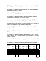
FLORIDA A&M UNIVERSITY’S INFORMATION TECHNOLOGY SYSTEMS GUIDELINES TABLE OF CONTENT Page 1 INTRODUCTION 3 APPROVED VENDOR QUALIFICATIONS 4 SPECIFICATIONS 4 SCOPE OF WORK 8 APPROVED PRODUCTS 11 TESTING AND ACCEPTANCE 15 WARRANTY & SERVICES 16 Page 2 Introduction 1. STATEMENT Florida A&M University, hereinafter referred to as the University, is seeking competitive quotes for the provision and installation of an information transport system to support high speed data communication including broadband transmissions. 2. STATEMENT OF PURPOSE The purpose of this Request for Quote (RFQ) is to secure the services of an experienced Belden-authorized Certified System contractor to design; provide install and a certified Belden structured cabling system. 3. TERM OF AGREEMENT 4. ISSUING OFFICE The sole point of contact with Florida A&M University for purposes of this RFQ is the “Issuing Office.” The contact information is listed below: Wayne Dunwoody Florida A&M University Enterprise Information Technology 1610 S. MLK Blvd Ste. 118 Tallahassee, FL 32307 Ph. 850-599-3560 5. RFQ TIMELINES The timeline applies to this solicitation as follows: Request for Quote issued: Date Sealed Quotes MUST be received in the Purchasing Office by 2:00 P.M., EST on: Date Posting of Intent to Award: Date Anticipated Contract Start: Date Page 3 APPROVED VENDOR QUALIFICATIONS Under the provisions of this request for quote, vendor shall provide the following qualifying document at the time of quote acceptance. Vendors’ failure to provide such documents will be disqualified as non responsive: The Vendor shall provide proof of current Belden CSV status and provide a letter from the Belden representative stating that vendor is fully certified to perform scope of work in compliance of specifications. Systems Contractor shall directly employ a minimum of six (6) skilled systems installers with current IBDN-700R course certificate of completion. Vendor shall provide names of staff that will be performing the installation. The Vendor shall provide proof of current membership of the 2012/2014 Corning Extended Warranty Program and must adhere to the engineering, installation and testing procedures and utilize the authorized manufacturer components and distribution channels in provisioning the Project. The Vendor shall be a licensed and registered with the State of Florida Department of Business Professional Regulation and who is, and who has been, regularly engaged in providing and installing non-residential, communication and technology systems The Vendor shall proof of one (2) RCDD on staff as permanent employees. The Vendor shall provide names, addresses and telephone numbers of references for the three (3) projects. Proof shall be required at the time of quote acceptance that the Vendor is an established organization, within (20) miles of the project, 27 00 00 COMMUNICATIONS 27 05 26 Grounding and Bonding for Communications Systems 27 05 26.01 General 27 05 26.01.A The facility should be equipped with a Telecommunications Bonding Backbone (TBB). This backbone should be used to ground all telecommunications cable shields, equipment, racks, cabinets, raceways, and other associated hardware that has the potential to act as a current-carrying conductor. The TBB should be installed independent of the building’s electrical and building ground and should be designed in accordance with the Page 4 recommendations contained in the ANSI/TIA/EIA-J-STD-607 Telecommunications Bonding and Grounding Standard. 27 05 26.01.B The main entrance facility/equipment room in each building should be equipped with a telecommunications main grounding bus bar (TMGB). Each telecommunications room should be provided with a telecommunications ground bus bar (TGB). The TMGB should be connected to the building electrical entrance grounding facility. The intent of this system is to provide a grounding system that is equal in potential to the building electrical ground system. Therefore, ground loop current potential is minimized between telecommunications equipment and the electrical system to which it is attached. 27 05 26.01.C All racks, metallic backboards, cable sheaths, metallic strength members, splice cases, cable trays, etc. entering or residing in the TR or ER should be grounded to the respective TGB or TMGB using a minimum #6 AWG stranded copper bonding conductor and compression connectors. 27 05 26.01.D All wires used for telecommunications grounding purposes should be identified with green or with a wrap of green tape insulation. Noninsulated wires should be identified at each termination point with a wrap of green tape. All cables and bus bars should be identified and labeled in accordance with the section 28 08 01, System Documentation, of this specification. 27 05 26.02 Grounding and bonding system installation 27 05 26.02.A The TBB should be designed and/or approved by a qualified PE, licensed in the state that the work is to be performed. The TBB should adhere to the recommendations of the ANSI/TIA/EIA-J-STD-607 standard, and should be installed in accordance with best industry practice. 27 05 26.02.B A licensed electrical contractor should perform installation and termination of the main bonding conductor to the building service entrance ground. 27 05 53 Identification for Communications Systems 27 05 53.01 General Labeling should be done in accordance with the recommendations made in the ANSI/TIA/EIA-606-A document, manufacturer's recommendations and best industry practices. Page 5 27 08 00 Commissioning of Communications 27 08 01 System Documentation 27 08 01.01 General 27 08 01.01.A Upon completion of the installation, the telecommunications contractor should provide three (3) full documentation sets to the Engineer for approval. 27 08 01.01.B Documentation should be submitted within ten (10) working days of the completion of each testing phase (e.g. subsystem, cable type, area, floor, etc.). This is inclusive of all test results and draft as-built drawings. Draft drawings may include annotations done by hand. Machine-generated (final) copies of all drawings should be submitted within 30 working days of the completion of each testing phase. At the request of the Engineer, the telecommunications contractor should provide copies of the original test results. 27 08 01.01.C The Engineer may request that a 10% random field re-test be conducted on the cable system, at no additional cost, to verify documented findings. Tests should be a repeat of those defined above. If findings contradict the documentation submitted by the telecommunications contractor, additional testing can be requested to the extent determined necessary by the Engineer, including a 100% re-test. This re-test should be at no additional cost to the Owner. 27 08 02 Test Results Documentation 27 08 02.01 General 27 08 02.01.A Test documentation should be provided on disk within three (3) weeks after the completion of the project. The disk should be clearly marked on the outside front cover with the words “Project Test Documentation”, the project name, and the date of completion (month and year). The results should include a record of test frequencies, cable type, conductor pair and cable (or outlet) I.D., measurement direction, reference setup, and crew member name(s). The test equipment name, manufacturer, model number, serial number, software version and last calibration date will also be provided at the end of the document. Unless the manufacturer specifies a more frequent calibration cycle, an annual calibration cycle is Page 6 anticipated on all test equipment used for this installation. The test document should detail the test method used and the specific settings of the equipment during the test as well as the software version being used in the field test equipment. 27 08 02.01.B The field test equipment should meet the requirements of ANSI/TIA/EIA-568-B. The appropriate level III tester should be used to verify Category 6 cabling systems. 27 08 02.01.C Printouts generated for each cable by the wire test instrument should be submitted as part of the documentation package. Alternately, the telecommunications contractor may furnish this information in electronic form (3.5" diskette, CD or memory stick). These diskettes, CDs or memory sticks should contain the electronic equivalent of the test results as defined by the bid specification and be of a readable format. 27 08 02.01.D When repairs and re-tests are performed, the problem found and corrective action taken should be noted, and both the failed and passed test data should be documented. 27 08 03 As-Built Drawings 27 08 03.01 General 27 08 03.01.A The drawings are to include cable routes and outlet locations. Outlet locations should be identified by their sequential number as defined elsewhere in this document. Numbering, icons, and drawing conventions used should be consistent throughout all documentation provided. Also, provide riser/backbone diagrams, racks and equipment layouts showing placement of all installed equipment shall be included. The Owner will provide floor plans in paper and electronic formats on which as-built construction information can be added. These documents will be modified accordingly by the telecommunications contractor to denote as-built information as defined above and returned to the Owner. 27 08 03.01.B The Contractors should annotate the base drawings and return a hard copy (same plot size as originals) and electronic form. 27 10 00 STRUCTURED CABLING All wiring will be in accordance with the ANSI/TIA/EIA-568-B and its addenda standard for telecommunications wiring. All copper RJ45 jacks will be wired in accordance with T568A wiring pattern. Page 7 The campus telecommunications systems derive from Perry Paige (data), Coleman Library Complex (video), and Foote-Hilyer (voice). The standard wiring plan for the University is to provide an acceptable outlet for any communications device (voice, data or video) which requires connection to other devices, networks, or information services serving general university needs. All new and upgrade work at the University should meet these guidelines unless otherwise directed. 27 10 01.01 General 27 10 01.01.A This document describes the products and execution requirements relating to furnishing and installing Telecommunications Cabling at the new, existing or remodeled buildings for Florida A & M’s Information Transport Systems Upgrade. Backbone and horizontal cabling comprised of copper cabling, and support systems are covered under this document. 27 10 01.01.B All cables and related terminations, support and grounding hardware should be furnished, installed, wired, tested, labeled, and documented by the Telecommunications contractor as detailed in this document. 27 10 01.01.C Products specifications, general design considerations, and installation guidelines are provided in this document. Quantities of telecommunications outlets, typical installation details, cable routing and outlet types will be provided as an attachment to this document. If the bid documents are in conflict, this specification should take precedence. The successful Vendor should meet or exceed all requirements for the cable system described in this document. 27 10 02 Regulatory references 27 10 02.01 General 27 10 02.01.A All work and materials should conform in every detail to the rules and requirements of the National Fire Protection Association, the local Electrical Code and current manufacturing standards. 27 10 02.01.B All materials should be UL Listed and should be marked as such. If UL has no published standards for a particular item, then other national Page 8 independent testing standards should apply and such items should bear those labels. Where UL has an applicable system listing and label, the entire system should be so labeled. 27 10 02.02 Reference list 27 10 02.02.A The cabling system described in this is derived from the recommendations made in recognized telecommunications industry standards. The following documents are incorporated by reference: ANSI/TIA/EIA-568-B.1 and its addenda ANSI/TIA/EIA-568-B.2 and its addenda TIA-569-B and its addenda ANSI/TIA/EIA-606-A ANSI/TIA/EIA-J-STD-607 ANSI/NECA/BICSI-568 ISO/IEC 11801 2nd edition CENELEC EN50173 27 10 02.02.B If this document and any of the documents listed above are in conflict, then the more stringent requirement should apply. All documents listed are believed to be the most current releases of the documents. The Contractor has the responsibility to determine and adhere to the most recent release when developing the quote for installation. 27 10 02.02.C This document does not replace any code, either partially or wholly. The contractor must be aware of local codes that may impact this project. 27 10 03 General condition –Approved Vendor 27 10 03.01 General 27 10 03.01.A The Contractor must be a Belden-authorized Certified System Vendor (hereinafter referred to as Belden CSV) of the Belden IBDN Gigabit System 2400. The Vendor must have successfully completed all Belden IBDN design and installation training provided by Belden. Contractor must also be a member of the 2007 Corning Extended Warranty Program and must adhere to the engineering, installation and testing procedures and utilize the authorized manufacturer components and distribution channels in provisioning the Project. Page 9 27 10 03.01.B The Contractor shall show proven expertise in the implementation of cabling projects. This expertise can be illustrated through the inclusion of details of at least three (3) projects involving the design and installation of a Category 6 unshielded twisted-pair (hereinafter referred to as UTP) cabling systems within the past two (2) year period. Names, addresses and telephone numbers of references for the three (3) projects should be included. Proof shall be required at the time of quote acceptance that the Firm or Company is an established organization, within (20) miles of the project, 27 10 03.01.C the Vendor. The successful bidder should hereinafter be referred to as 27 10 03.01.D The Vendor should accept complete responsibility for the design, installation, acceptance testing and certification of the Belden IBDN Gigabit System 2400. 27 10 03.01.E The Vendor should provide proof of current Belden CSV status and should deliver the Belden certification of the installed Belden IBDN Gigabit System 2400 to the Purchaser. 27 10 04 General condition –Approved Installer 27 10 04.01 General 27 10 04.01.A The vendor must be a Belden-authorized Certified System Vendor (hereinafter referred to as Belden CSV) of the Belden IBDN Gigabit System 2400. The Vendor must have successfully completed all Belden IBDN design and installation training provided by Belden. The vendor shall be a licensed and registered with the State of Florida Department of Business Professional Regulation and who is, and who has been, regularly engaged in providing and installing non-residential, communication and technology systems of this type and size for at least the immediate past five (5) years and one (1) RCDD on staff as permanent employees. The Contractor's Project Manager, Foreman, and Technicians shall possess current 2007 Belden’s IBDN-700R certificate of completion for the system being provided. 27 10 04.01.B The installation of the Belden IBDN Gigabit System 2400 should be performed by employees of the Vendor and shall be required to provide proof of Belden authorization to install a Belden IBDN Gigabit System 2400. Installers: Due to the time restriction and the accelerated project schedule the Systems Contractor shall directly employ a minimum of six (6) skilled systems installers with current 2007 IBDN-700R course certificate of completion and whose normal work is systems installation, who shall provide all Page 10 systems equipment and who shall make the wire and cable connections thereto. 27 10 04.01.C All work should be performed and supervised by technicians and managers qualified to install and test the Belden IBDN Gigabit System 2400 in accordance with Belden requirements. The supervisor should have a minimum of 5 years experience and successfully completed Belden IBDN installation training provided by Belden. 27 10 05 General condition –Approved products 27 10 05.01 Approved products 27 10 05.01.A Here is a list of approved products. Approved 4-pair UTP Cable: Belden IBDN Gigaflex 2400 Cable series (Cat. 6) Approved RG 6 Cable: Belden 1189AP Coax Approved high pair count UTP Cable manufacturer: Belden Approved UTP connector product manufacturer: Belden Approved Rack and Cabinet manufacturer: Belden Approved IDC cross-connect system manufacturer: Belden Approved Patch Panel manufacturer: Belden Approved UTP Patch Cord manufacturer: Belden Approved Fiber Optic Cable: Corning Cable Systems 27 10 05.02 Equivalent products 27 10 05.02.A Due to the nature and type of communications all products, including but not limited to faceplates, jacks, patch panels, racks, IDC blocks, copper cable products and patch cords, for the purpose of this document, should be manufactured by Belden. There will be no substitutions allowed. Page 11 27 10 07 Work Included 27 10 07.01 General 27 10 07.01.A The work included under this specification consists of furnishing all labor, equipment, materials, and supplies and performing all operations necessary to complete the installation of this structured cabling system in compliance with the specifications and drawings. The Telecommunications contractor will provide and install all of the required material to form a complete system whether specifically addressed in the technical specifications or not. 27 10 07.01.B following: The work should include, but not be limited to the Pre-Register project as a Belden IBDN Certified Project with Belden. Furnish and install a complete telecommunications wiring infrastructure. Furnish, install, and terminate all UTP cable. Furnish and install all wall plates, jacks, patch panels, and patch cords. Furnish and install all required cabinets and/or racks as required and as indicated. Furnish any other material required to form a complete system. Perform channel testing (100% of horizontal and/or backbone links) and provide channel pass result report. Furnish test results of all cabling to the Owner on diskette, CD or memory stick and paper format, listed by each closet, then by workstation ID. Adhere and comply with all requirements of Belden programs. Provide Owner training and documentation (Testing documentation and As-built drawings). 27 10 08 Drawings specification 27 10 08.01 General 27 10 08.01.A It should be understood that the electrical details and drawings provided with the specification package are diagrammatic. They are included to show the intent of the specifications and to aid the telecommunications contractor in bidding the job. The telecommunications Page 12 contractor should make allowance in the quote to cover whatever work is required to comply with the intent of the plans and specifications. 27 10 08.01.B The telecommunications contractor should verify all dimensions at the site and be responsible for their accuracy. 27 10 08.01.C Prior to submitting the quote, the telecommunications contractor should call the attention of the owner to any materials or apparatus the telecommunications contractor believes to be inadequate and to any necessary items of work omitted. 27 10 10 Delivery, Storage and Handling 27 10 10.01 General 27 10 10.01.A Delivery and receipt of products should be at the site described in the section 27 10 01, Scope. 27 10 10.01.B Cable should be stored according to manufacturer's recommendations as a minimum. In addition, cable must be stored in a location protected from vandalism and weather. If cable is stored outside, it must be covered with opaque plastic or canvas with provision for ventilation to prevent condensation and for protection from weather. If air temperatures at cable storage location will be below 4.4 degree C (40 degrees F.), the cable should be moved to a heated 10 degrees C. (50 degrees F.) minimum location. If necessary, cable should be stored off site at the contractor's expense. 27 10 10.01.C If the telecommunications contractor wishes to have a trailer on site for storage of materials, arrangements should be made with the Owner. 27 10 11 Structured cabling overview NOTE: All backbone fiber patch cords must be Corning or Belden products. All infrastructure products for retrofitting or new construction, (i.e. wall outlets, category 6 patch cords, etc.) must be a product of Corning or Belden. These requirements are a must to stay in accordance and maintain the University's current 25-year warranty on all products and materials. All contractors must be Corning EWP certified and Belden CSV certified, please refer to the Installer / Contractor Requirements Section. Requirements Page 13 Networking Switching, Wireless & Routing Infrastructures The University has standardized and built a Secure Network Infrastructure around the Cisco Systems Hardware & Security platform. Additional information provided by Director of Network Infrastructures upon request. Copper to the Desktop All communication outlets will be equipped with but not limited to two (2) category 6, twisted pair copper station wiring, both terminating in a RJ45 modular jack. Unless otherwise specified in the design phase, all cables will terminate to a category 6 patch panel within the wiring closet. A category 6 patch panel will be installed to connect with the telephone company demarcation point. All connections between the active data equipment and/or the voice patch panels to the category 6 station wiring patch panel will be accomplished through category 6 RJ45 jumpers. Wireless Network All new and retro-fitted facilities are required to have wireless communications. Refer to the Wireless Network Documentation and Director of Networking Infrastructures for special design due to the rapid ever changing in wireless technology. Classrooms / Teaching Labs Smart Classrooms All Teaching Labs and Classrooms must be equipment with Smart Teaching Technology. The University has standardized on Crestron as the Smart Classroom equipment for unilateral installation across campus classrooms. All requests for Classroom Retrofit / Upgrade to Smart Technology must be submitted to University’s EIT Networking Director or University’s Instructional Media Director for Design specifications and Cost. The departments will meet with requesting customers and design according to University standards along with meeting the needs of the requestor. There shall be three (2) floor level floor boxes containing brass cover plates and sub plate hardware and fittings as required. One (1) floor box shall be for quad electrical outlet and quad datacom outlet. Two (1) floor boxes shall be for audio/visual connectivity. The A/V floor boxes shall have a minimum 1 ½” & ¾” pathway. Page 14 Floor boxes shall installed approximately 5’ from front wall & 5’ from side wall (front corner of room) and opposite side of the room from entrance door. The total foot print of floor boxes shall be less than 24” x 24”. All floor boxes shall have continuous pathway installed from the floor box to above ceiling for projector connectivity. Exact projector location must be verified prior to installation. There also shall be a ceiling mount duplex electrical outlet and data outlet located next to the ceiling mount projector location. GENERAL All station wiring will be continuous wire from the telecommunications spaces (MDF/IDF) to the communication outlet, All telecommunications spaces (MDF/IDF) terminations shall be of 100% cross connected as per the ANSI/TIA/EIA-568-B and its addenda specifications. To facilitate future cable installations, a new pull string shall be installed in conduits simultaneously with the pull-in of cable. All telecommunications spaces (MDF/IDF) shall be provided with one or more grounded 19" by 84" EIA standard wiring rack(s) and category 6 patch panels / Rack mount fiber termination cabinets or splice housings in quantities necessary to terminate the required cables. Appropriate wire management hardware will be provided to support routing of patch cables in a neat and organized manner. The electrical work shall include requirements for installation of a conduit (1" minimum diameter) from each communication outlet and "stubbed" up above ceiling level. A pull string and appropriate junction or "pull" boxes shall also be provided in each conduit run to facilitate future installation of cable(s). Cable trays shall be installed to route the station cable to the telecommunications spaces (MDF/IDF). All I telecommunications spaces (MDF/IDF) and connecting blocks must be properly identified according to specifications provided by the Information Resource Manager. All cable pairs in copper riser cables or the copper entrance cable must be terminated on Category 6, 110 style to RJ45 patch panels and identified according to ANSI/TIA/EIA 606-A specifications. Fiber runs between telecommunications spaces (MDF/IDF) shall consist of a 12 fiber 62.5/125 micron multimode cable and a 12 fiber single-mode cable terminated in SC connectors and placed in appropriate fiber patch panels. Page 15 All communication outlets not in use, either wired or empty, must have a blank plate covering the outlet. All modular jack assemblies must be labeled and identified according to ANSI/TIA/EIA 606-A specifications. All wiring inside of rooms should be protected by conduit or other means such as wire mold. Cable may be run exposed above ceilings, provided this cabling is supported independent of other utilities, such as conduits, pipes, ceiling support systems, cable trays, and not laid directly on the ceiling panels. Cable to be plenum rated. All patch cables both copper and fiber are to be provided by the contractor at the time of completion. All copper patch cables are to be category 6 compliant and 7’ in length. All telecommunications spaces (MDF/IDF) patch cords should be 3 meters sc-sc type. Terminations Faculty/Administrative 0ffices - Each office shall have one communication outlet per 80 square feet. ((2) CAT6 per outlet) Clerical/Staff Offices - One communication outlet per designated occupant plus one spare cabled outlet for every two (2) occupants or fraction thereof or one communication outlet per 80 square feet whichever is greater. ((2) CAT6 per outlet) Secretary/Administrative Assistant Offices - One communication outlet per designated occupant plus two outlets per office area or 2 extra outlets per five people or one communication outlet per 80 square feet whichever is greater. ((2)CAT6 per outlet) This extra facility allows for future growth and/or high density office/business machines used concurrently with other staff activities (perhaps facsimile transmission while using a word processor). Conference Rooms - One communication outlet per 80 square feet with two CAT6 per outlet with a minimum of (1) Wireless Access Point with a presentation system per conference room. Power should be installed underneath the conference table and (1) media mount should be installed on top of table to support Laptops, Tablets, smart phones and etc. to display content to Projector or LED. Dormitories - One data communication outlet and one F type coaxial outlet for each planned occupant per dormitory room. (1) RJ45 (CAT6) per pillow. If the Page 16 unit is single room, multiple occupancy units, the above specifications will apply to the room. All dormitory building facilities will also be provided with direct fiber optic connection to the campus backbone. This connection will consist of (12) 62.5/125 micron multimode fibers and (12) single mode fibers. Each dormitory facility will also include a Main Data Closet to house the active (SWITCH) equipment and the terminated fibers to the campus backbone. Two 48port POE switches per building & 6 - 10 access points per floor (transmission & security scanning) for the Wireless Network. Facilities Trunk and Access Facilities Copper (Twisted Pair / Coaxial) cables from the communication outlets described in the previous section should be connected to an accessible telecommunications spaces (MDF/IDF) close to the center of the terminations on each floor rather than at the single (or major) communications room for the building. The fiber cables from the communication outlets described in the previous section should be routed through an accessible telecommunications spaces (MDF/IDF) close to the center of the terminations on each floor and either home run or fusion splice onto high count riser cables that lead to the MDF where all data communications electronics will be located. Spaces, for a communications trunk to support future instructional needs, must interconnect laboratory, classroom, office pad areas, and the building communications equipment room. Cable tray (preferred and greater than 6 inch cross section) or a 4" conduit is an appropriate facility (raceway) if the actual needs are not known, Telecommunications Spaces General Space for connection of the building circuits to the outside plant should be provided as a separate room and not shared with other utility services, particularly the electrical service. When possible, it will not be adjacent to the electrical distribution room. Minimum room size for the main telecommunications spaces (MDF) is 3m (10ft) x 3.4m (11ft) and minimum room size for the other telecommunications spaces (IDF) is 3m (10ft) x 2.4m (8ft). The project architect/Engineer must, during the initial (Schematic-Preliminary) Planning stage, engage coordinated efforts Page 17 of the Information Resource Manager’s Office, Facilities Management and the Using Agency to assure appropriate size, location and arrangement of the telecommunications spaces (MDF/IDF). Special size request must be discussed and signed off by Director of Networking Infrastructures to ensure the University meets OSHA Standards and present a safe work environment for Network engineers. Each telecommunications spaces (MDF/IDF) must have proxy card readers installed at doors. EIT shall determine which telecommunications spaces (MDF/IDF) will accommodate non-EIT equipment (i.e. Fire control panels, access control panels, burglary equipment, etc.). Each telecommunications spaces (MDF/IDF) shall have a Net Botz 5000 appliance mounted for environmental & security controls. Electrical & data outlets shall be installed next to the Net Botz 5000 location. Telecommunications spaces (MDF/IDF) shall a portable fire extinguishers (e.g., with appropriate ratings) mounted as close to the entrance as possible and shall not have water pipes of any kind installed above ceiling. Telephone - At least 1 Telephone per telecommunications spaces (MDF/IDF). Lighting - All telecommunications spaces (MDF/IDF) shall have a light intensity of 50-70 foot candles at 30 inches above the floor. Dust Elimination - The walls, floors, and ceiling of all telecommunications spaces (MDF/IDF) shall be painted or otherwise treated to eliminate dust. If the walls are painted, light colored, latex type paint should be used. Backboards - All telecommunications spaces (MDF/IDF) shall have gray fire retardant 8'x4'x3/4"A/C grade plywood backboards mounted on the back and side walls. The plywood backboard shall be affixed in such a manner that it will adequately support the weight of the cable, terminals, and other equipment that will be attached to it. The plywood backboard shall be treated with a fire retardant material. Vertical Risers - Telecommunications spaces (MDF/IDF) contain the vertical cable riser space. The communications equipment rooms shall then provide vertical riser sleeves and bushings through the floor and/or ceiling to other vertically stacked communication equipment rooms. All sleeves shall be a minimum of 4 inches in diameter or sized to support the actual cabling requirements whichever is greater. Every communications equipment room should be equipped with a minimum of 5 riser sleeves; 2 for voice, 2 for data and 1 for video or any additional sleeves as required by actual cable needs. Page 18 The communication equipment rooms shall be centrally located to optimize the length of the cable run to the telephone outlets. The length of a cable run shall not exceed 290 feet. In multi-level buildings, the communications equipment rooms should be located over the vertical cable riser space, Room Temperature and Humidity The HVAC should: 1. Maintain a continuous and dedicated environmental control (e.g., 24 hours per day, 365 days per year). If emergency power is available, the designer should connect it to the HVAC system that serves the telecommunication spaces. 2. Maintain a positive pressure with a minimum of one air change per hour in the telecommunications spaces. The ambient temperature shall be maintained between 60 and 68 degrees Fahrenheit and the relative humidity shall be maintained between 20 and 50 percent, unless otherwise specified. Temperature, and humidity requirements are on a 24-hour, 7 day-a-week basis regardless of the heat generated by normally operating communication equipment. Special ventilation may be required for a battery back-up system in some buildings. Electrical Facility Relationships Building earth ground must be provided for all communications equipment rooms such that the DC resistance from the rooms to the building earth ground on the longest run does not exceed 0.5 ohms. Telecommunications spaces (MDF/IDF) shall have two (2) 20 AMP 220V dedicated, non-switched electrical outlets, one (1) 30 AMP 220V dedicated, non-switched electrical outlet and two quad 120V, 20 amp convenience outlets installed behind equipment racks. Convenience outlets shall be 1.83 m (6ft) apart. Outlets must be isolated from any motors, air conditioning or lighting circuits must be provided irrespective of room size. A separate small sub-panel with integrated surge suppression would provide the proper isolation in the telecommunications spaces (MDF/IDF) Each communication outlet (equipped or wired for) must be provided with a 12OV, 20 amp circuits with duplex outlet whose feed is isolated from any motors, air conditioning or lighting circuits. Lock Access to all rooms or closets containing voice or data equipment will be through one uniform master key system. The standard key for all communications closets shall be a unique key under the Best lock grand master Page 19 key system. No key will be issued by the Key Bank without the signed approval of the C.I.O Security All MDF and IDF must have Proxy access. All users must be approved by the Director of Network Infrastructure and C.I.O. Outside Plant All new building construction planning must include a connection into existing tunnels or manholes and should connect via five (5) 4" conduits. These conduits would be for the data, voice and video facilities only. Whenever possible, all abandoned cable should be removed from tunnels, manholes, and conduit. If it is not feasible to remove said cable, it should be clearly tagged as abandoned and should be reported to the Information Resource Manager. No cable should be installed in any facilities (raceways) other than those intended for that use. Gas pipe and water pipes must not be used for conduit under any circumstances. All buildings shall be wired with a 75 OHMS RG6 U coaxial cable. All buildings video topology shall be star-wired to a closed-circuit television (CCTV) stainless steel communications wall plate with F81 barrel splice termination. The signal strength at the F81 wall plate outlet shall be measured at no more than l0dB. All connectors shall be one-piece crimp-on. All connections between the CCTV backbone network and the building communications closet shall be made with jacketed 1/2" coaxial cable or Single-mode fiber. All new building construction planning must include a connection to the campus fiber optic backbone which terminates in the Perry-Paige building. This backbone connection must consist of a 48 strand composite fiber optic cable (24 – Single-mode and 24 Multimode. Outside Plant Fiber Optic Cable Specifications The 48 strand composite cable shall consist of 24 Multi Mode fibers and 24 Single Mode fibers with 2 sub groupings distributed as follows: 1 Multi Mode sub Page 20 groupings containing 24 multi-mode fibers each and 1 single mode sub grouping containing 24 single-mode fibers. The Multi mode sub grouping will be individually color coded. The Single mode sub grouping will be individually color coded and imprinted with a black stripe or hash mark imprinted on the buffer tube. Multimode Fibers: All multi-mode fibers will be 62.5/125micron fiber. All cables will be of loose tube construction with the following fiber specifications: 100 KPSI proof tested; Core diameter 62.5um +/- 3um; Cladding diameter 125um +/- 2um; Core NonCircularity less than or equal to 6%; Cladding Non -Circularity less than or equal to 2%; Numerical Aperture of 0.275 +/- 0.015; Coating Concentricity Greater than or equal to 0.7; Primary coating shall be 250 +/- 15 micron dual layered UV cured acrylate applied by the fiber manufacturer which may be mechanically or chemically stripped without damaging the fiber; Multi Mode attenuation less than or equal to 3.5 db/km @ 850nm and 1.5 db/km @ 1300nm; minimum bandwidth of 160 MHz @ 850nm and 500 MHz @ 1300nm (this specification shall be a maximum attenuation for each fiber over the entire operating temperature range of the cable). Single-mode Fibers: All Single Mode fibers will be 8.3/125 micron fibers. All cables will be of loose tube construction with the following fiber specifications: 100 KPSI proof tested; Core diameter 8.3um; Numerical Aperture of 0.13; Cladding diameter 125um +/- 2um; Core to cladding offset of less than or equal to 0.8um; Cladding NonCircularity of less than or equal to 1.0%; Coating Concentricity Greater than or equal to 0.7; Primary coating shall be 250 micron dual layered UV cured acrylate applied by the fiber manufacturer which may be mechanically or chemically stripped without damaging the fiber; The cabled fiber cutoff wavelength shall be less than or equal to 1250nm; Attenuation Uniformity - no point of discontinuity greater than 0.1db at either 1310nm or 1550nm; Single Mode attenuation less than or equal to 1.0 db/km @ 1310nm and .75 db/km @ 1550nm (this specification shall be a maximum attenuation for each fiber over the entire operating temperature range of the cable). Network Design Each building or physically connected building complex will support user connections at 100/1000 full duplex switch Ethernet speed. The main switch for the building shall be equipped with an Gigabit switch capable of performing LES/BUS/LANE functions should it’s connection from the campus backbone become inoperative and should connect to the campus backbone via redundant load sharing Gigabit Single mode or Multimode links. Page 21 Network Switching Equipment Each network switch will have as a minimum the following functions. Backplane support for switched GBPS speeds Ethernet. Backplane support for Gigabit switching Uplink capability forms the switched Ethernets to the Gigabit switch fabric. Each switch shall include redundant load balancing power supplies capable of N+1 redundancy. Full SNMP Management of all chassis/bridging functions. Support the LANE, PNNI, and MPOA standards that are current at the time of acquisition. Support upgrades to Layer 3 switching as the standards become established. Full RMON support for all RMON groups standardized at the time of acquisition. Per port RMON / RMON II support for all switched Ethernet ports as well as port replication. Support for out of band / side band network management via isolated 1000 MB or 10gigE Ethernet Wiring Closet Power Supplies Each wiring closet will be provided with one or more rack mounted uninterruptable power supplies of sufficient capacity to power all active data equipment within the closet Each UPS will be fully SMNP manageable or shall be capable of being managed through the switching equipment. 27 10 11.01 General 27 10 11.01.A The systems chosen should meet the specifications as described in this subsections. The UTP-based cabling system shall have a 250 MHz Channel Bandwidth over a maximum distance of 100m (328 ft) and a positive channel Power Sum Attenuation-to-Crosstalk Ratio (PSACR) up to 250 MHz. Page 22 The UTP-based cabling system shall use matched components from a single manufacturer, and the cabling system shall be certified to deliver system performance over the lifetime of the applications for which the cabling system was originally designed to support. All components used in the UTP-based cabling system shall be warranted for a period of 25 years from date of installation against defects in materials and/or workmanship. The UTP-based cabling system shall comply with the following standards: ANSI/TIA-EIA-568-B.2-1 (Category 6 addenda) Class E ISO/IEC 11801 2nd edition Class E - CENELEC EN50173 The UTP-based cabling system should be capable of supporting the following applications: 2.4 Gb/s ATM (When using the same transmission technique as Gigabit Ethernet 1.2 Gb/s ATM (When using the same transmission technique as Gigabit Ethernet Gigabit Ethernet (1000BASE-T) Broadband Video 25/52/155/622 Mb/s ATM Fast Ethernet (100BASE-TX, 100BASE-T4) 100VG-AnyLAN TP-PMD Ethernet (10BASE-T) 4/16 Mb/s Token-Ring Baseband Video ARCnet/ARCnet Plus IBM System 370/3270 IBM 3x - AS/400 IBM 4700 Financial Communication System IBM 5080/6090 Graphics System EIA-232/EIA-422 Voice 27 10 11.01.B The systems chosen should meet the performance specifications as described: Parameters Frequency Standards* Performance Requested Page 23 PSNEXT Insertion Loss PSACR PSELFEXT Return Loss 100 200 250 100 200 250 100 200 250 100 200 250 100 200 250 MHz MHz MHz MHz MHz MHz MHz MHz MHz MHz MHz MHz MHz MHz MHz Propagation Delay Delay Skew Available Bandwidth 37.1 dB 31.9 dB 30.2 dB 21.3 dB 31.5 dB 35.9 dB 15.8 dB 0.4 dB -5.8 dB 20.3 dB 14.2 dB 12.3 dB 12.0 dB 9.0 dB 8.0 dB 555 ns 50 ns 40.8 dB 35.6 dB 33.3 dB 19.9 dB 29.3 dB 33.3 dB 20.9 dB 6.3 dB 0.1 dB** 25.8 dB 19.7 dB 17.8 dB 14.0 dB 10.0 dB 9.0 dB 490 ns 25 ns 200 MHz 250 MHz Worst case scenario for four-connector topology *Based on ANSI/TIA/EIA-568-B.2-1 (Cat. 6 addenda – July 2002) ISO/IEC 11801 2nd edition (September 2002) **Positive PSACR @ 250 MHz 27 10 12 Testing and acceptance 27 10 12.01 General 27 10 12.01.A All cables and termination hardware should be 100% tested for defects in installation and to verify cabling system performance under installed conditions according to the requirements of ANSI/TIA/EIA-568-B. All pairs of each installed cable should be verified prior to system acceptance. Any defect in the cabling system installation including but not limited to cable, connectors, feed through couplers, patch panels, and connector blocks should be repaired or replaced in order to ensure 100% useable conductors in all cables installed. 27 10 12.02 Copper channel testing 27 10 12.02.A All twisted-pair copper cable links should be tested for continuity, pair reversals, shorts, opens and performance as indicated. Additional testing is required to verify Category performance. Horizontal cabling should be tested using a Level III test unit for category 6 performance compliance. Page 24 27 10 12.02.B Continuity - Each pair of each installed cable should be tested using a test unit that shows opens, shorts, polarity and pair-reversals, crossed pairs and split pairs. The test should be recorded as pass/fail as indicated by the test unit and referenced to the appropriate cable identification number and circuit or pair number. Any faults in the wiring should be corrected and the cable re-tested prior to final acceptance. 27 10 12.02.C Length - Each installed cable link should be tested for installed length using a TDR type device. The cables should be tested from patch panel to patch panel, block to block, patch panel to outlet or block to outlet as appropriate. The cable length should conform to the maximum distances set forth in the ANSI/TIA/EIA-568-B Standard. Cable lengths should be recorded, referencing the cable identification number and circuit or pair number. For multi-pair cables, the shortest pair length should be recorded as the length for the cable. 27 10 12.02.D Category 6 Performance - Performance testing should be done according to the published ANSI/TIA/EIA-568-B.2-1 Standard. 27 10 13 Warranty and services 27 10 13.01 Qualification of system 27 10 13.01.A The installed Belden IBDN Gigabit System 2400 will be covered by a certification program provided by Belden and the Certified System Vendor. 27 10 13.01.B Telecommunications spaces and pathways in new buildings or in those buildings having undergone major renovations in the preceding three (3) years should conform to the requirements per TIA-569-B. In cases of installations in restrictive spaces and pathways, where it is impossible to implement the aforementioned requirements, the cabling runs should not exceed the maximum distances specified in ANSI/TIA/EIA-568-B and should not in any manner diminish the performance of the Belden IBDN Gigabit System 2400. 27 10 13.01.C The installed Belden IBDN Gigabit System 2400 should conform to all applicable local building and electrical codes. 27 10 13.02 Certification 27 10 13.02.A To qualify for system certification, Belden IBDN Gigabit System 2400 should be designed, engineered, installed and tested by a Belden CSV. Page 25 27 10 13.02.B To qualify for system certification, the installed cabling system should fully comply with all relevant Belden IBDN design and applications guidelines, including acceptable deviations as specified in the latest release of the Belden IBDN Certification Guide. 27 10 13.02.C To qualify for system certification, only Belden approved products should be used to ensure end-to-end system performance. The full Belden product warranty and lifetime performance assurance can be provided only to systems built using products supplied by Belden for the Belden IBDN system. 27 10 13.02.D Belden will not provide certification coverage for other manufacturers’ products. 27 10 13.03 Lifetime application assurance 27 10 13.03.A Belden IBDN certification should provide the assurance that all present and future applications engineered for the performance level of the cabling system used will work for the lifetime of the certified Belden IBDN Gigabit System 2400. 27 10 13.03.B Should the certified Belden IBDN Gigabit System 2400 fail to support the application(s) designed to operate over it—whether at the time of cutover to the new cabling system, during subsequent use, or after upgrading to a newer supported application (for example, to a Gigabit Ethernet or an ATM network from a lower-speed network environment)—Belden and the Vendor should take prompt corrective action. 27 10 13.04 25-year product warranty 27 10 13.04.A Belden IBDN certification should provide a twenty-five year product warranty for all Belden IBDN passive components used in the installed Belden IBDN Gigabit System 2400. Defective and/or improperly installed products should be replaced and/or correctly installed at no cost to the Purchaser. 27 10 13.05 Purchaser Responsibility 27 10 13.05.A The Vendor should provide a Belden IBDN User Manual to the Purchaser. This document describes essential system elements and specifies Purchaser responsibilities for maintaining the integrity of the installed cabling system over time. The Belden IBDN User Manual contains guidelines for cabling system expansions and modifications - such as relocations, additions Page 26 and changes to services - in addition to labeling and record-keeping requirements. 27 10 13.05.B The Purchaser accepts that the benefits offered by certification are nullified if non-approved products are introduced into the installed Belden IBDN Gigabit System 2400. To regain system certification in such cases, a Belden CSV must correct and approve all modifications deemed necessary by Belden. 27 11 16 Communications Cabinets, Racks, Frames and Enclosures 27 11 16.01 Racks 27 11 16.01.A All racks and wire management should be Belden specific. The equipment rack should provide vertical cable management and support for the patch cords at the front of the rack and wire management, support, and protection for the horizontal cables inside the legs of the rack. The free-standing rack should be: Ordering Number BHRR194 27 11 16.02 Description Seven foot equipment, Black, 44U Rack installation 27 11 16.02.A Racks should be securely attached to the concrete floor using a minimum 3/8” hardware or as required by local codes. 27 11 16.02.B Racks should be placed with a minimum of 36 inch clearance from the walls on all sides of the rack. When mounted in a row, maintain a minimum of 36 inches from the wall behind and in front of the row of racks and from the wall at each end of the row. 27 11 16.02.C All racks should be grounded to the telecommunications ground bus bar in accordance with section 25 05 26, Grounding and Bounding for Communications Systems of this document. 27 11 16.02.D Screws not used for installing rack mount patch panels and other hardware should be bagged and left with the rack upon completion of the installation. Page 27 27 11 16.02.E Rack mount termination equipment fields should be installed as per the requirements specified by the manufacturer’s installation guides. 27 11 16.02.F Wall mounted termination block fields should be mounted on 4’ x 8’ x .75” void free plywood. The plywood should be mounted vertically 12” above the finished floor. The plywood should be painted with two coats of white fire retardant paint. 27 11 16.02.G Wall mounted termination block fields should be installed as per the requirements specified by the manufacturer’s installation guides. 27 11 19 Communications Termination Blocks and Patch Panels 27 11 19.02 GigaFlex PS6+ Patch Panel 27 11 19.02.A General The GigaFlex PS6+ patch panel system should provide a category 6 centralized, rack-mounted termination, identification and service assignment point for UTP horizontal, backbone and equipment cabling at the horizontal or main cross connect using modular cord assemblies. 27 11 19.02.B Mounting Hardware The UTP cross-connect/interconnect system should be available in 24- and 48port configurations for greater design flexibility and optimization of rack installation. The UTP cross-connect/interconnect system should be compatible with standard 19” equipment racks, cabinets or wall-mount brackets. The UTP cross-connect/interconnect system should have an integrated rear cable management bar that can be positioned at different heights to accommodate any installation need. The UTP cross-connect/interconnect system should have all ports numbered on the front and back of the panel. The UTP cross-connect/interconnect system should have large front labeling space to facilitate custom port identification. Page 28 The UTP cross-connect/interconnect system should have openings for colorcoded icons. 27 11 19.02.C Connection Module The connection module should be backward compatible with category 5e. The connection module should be based on the encapsulated lead frame technology providing long term reliability and stability. The connection module should allow termination of both T568A and T568B wiring configurations. The connection module used in the rack-mount UTP crossconnect/interconnect system shall be made of fire-retardant UL 94V-0 plastic. The connection module used should have an insulation displacement connection featuring insulation-slicing, tin-plated clips, forming a gas-tight connection. The connection module should have a contact resistance of 1 mΩ per contact. The connection module should have a durability rating of 10 insertions of any combination of 22 to 24 AWG wire. The jack in the connection module should be FCC Part 68, Subpart F and IEC 603-7 compliant. The durability of the IDC termination on the connection module should be 1000 mating cycles. The contact material of the IDC termination on the connection module should be phosphor bronze, plated with 50 micro-inches of gold over nickel. The maximum current rating of the IDC termination on the connection module should be 1.5 amperes. The dielectric strength of the IDC termination on the connection module should be 1000V RMS at 60 Hz for one minute. The minimum insulation resistance of the IDC termination on the connection module should be 200 MΩ. Page 29 The modular plug should meet or exceed the requirements per ANSI/TIA/EIA568-B.2-1 parameters when tested with PS6 Connectivity at 100 MHz. Parameter NEXT PSNEXT FEXT PSFEXT Attenuation Return Loss 27 11 19.02.D Part Number IBDN PS6LX Modular Plug Values (dB) 55.1 52.0 49.8 46.9 0.1 27.0 Category 6 (dB) 54.0 50.0 43.1 40.1 0.2 23.0 The modular patch panel shall be one of the following: Description AX101611 GigaFlex PS6+ Patch panel, 1U, 24-port, BLACK AX101613 GigaFlex PS6+ Patch panel, 2U, 48-port, BLACK (other colors are available) 27 11 19.04 Flex Patch Panel 27 11 19.04.A General The Flex patch panel system should provide a category 6 centralized, rackmounted termination, identification and service assignment point for UTP horizontal, backbone and equipment cabling at the horizontal or main cross connect, using modular cord assemblies. 27 11 19.04.B Mounting Hardware The UTP cross-connect/interconnect system rack mount should allow the flexibility of up to 144 port configurations. The UTP cross-connect/interconnect system rack mount should be provided in gray or black for greater design flexibility. The UTP cross-connect/interconnect system rack mount should feature optional wire management to secure cable bundles, control and maintain proper cable bend radius and provide physical protection for terminations. The UTP cross-connect/interconnect system rack mount should be compatible with the 19 in. equipment racks, cabinets or wall mount brackets. Page 30 The UTP cross-connect/interconnect system rack mount should have a 16-gauge sheet metal construction and the module holder should be made of fireretardant plastic construction compliant with UL94HB, black. The UTP cross-connect/interconnect system rack mount offer a large front labeling space to facilitate port identification and be able to use laser printable labels for clear identification and to ease network management. The UTP cross-connect/interconnect system rack mount should have an integrated rear cable management bar for neat cable dressing. The UTP cross-connect/interconnect system rack mount should be compatible with color-coded modules. 27 11 19.04.C Connection Module: See 27 15 43.03, Modular Jacks. 27 11 19.04.D Ordering Number AX101456 The modular patch panel should be one of the following: Description Flex patch panel, Modular, 1U, 24-port, Black AX101458 Flex patch panel, Modular, 2U, 48-port, Black (Other colors are available) 27 11 19.05 Copper Termination hardware installation 27 11 19.05.A Cables should be dressed and terminated in accordance with the recommendations made in the ANSI/TIA/EIA-568-B standard document, manufacturer's recommendations and installation guides, and best industry practices. 27 11 19.05.B (0.5 inch). Pair untwist at the termination should not exceed 13 mm 27 11 19.05.C Bend radius of the UTP cable in the termination area should not exceed 4 times the outside diameter of the cable. 27 11 19.05.D Cables should be neatly bundled and dressed to their respective panels or blocks. Each panel or block should be fed by an individual bundle separated and dressed back to the point of cable entrance into the rack or frame. Page 31 27 11 19.05.E Each cable should be clearly labeled on the cable jacket behind the patch panel at a location that can be viewed without removing the bundle support ties. Cables labeled within the bundle, where the label is obscured from view should not be acceptable. 27 13 00 Communications Backbone Cabling 27 13 13 Communications Copper Backbone Cabling 27 13 13.01 Backbone cables 27 13 13.01.A General The backbone cabling is the portion of the cabling system that links the crossconnects within a building and between buildings in a campus environment. The backbone cabling consists of the feeder field of the horizontal crossconnect, intrabuilding and interbuilding backbone cable and intermediate and main cross-connects. 27 13 13.01.B 100 Ohm Category 6 unshielded twisted-pair cable (UTP) GigaFlex 2400 cables series See section 27 15 13.02.B, 100 Ohm Category 6 unshielded twisted-pair cable (UTP) - GigaFlex 2400 cables series. 27 13 13.01.C RG 6 Quad Shield Coax 1189AP cable Belden See section 27 15 13.02.C, 100 Ohm Category 6 unshielded twisted-pair cable (UTP) - MediaTwist cables series. 27 13 13.01.D Corning Cable Systems Fiber Optic cable 27 13 13.02 Backbone cables installation 27 13 13.02.A Backbone cables should be installed separately from horizontal distribution cables. 27 13 13.02.B A plastic or nylon pull cord with a minimum test rating of 90 Kg (200 lb.) should be co-installed with all cable installed in any conduit. 27 13 13.02.C Where cables are housed in conduits, the backbone and horizontal cables should be installed in separate conduits. Page 32 27 13 13.02.D Where cables are installed in an air return plenum, riser rated cable should be installed in metallic conduit. 27 13 13.02.E Where backbone cables and distribution cables are installed in a cable tray or wireway, backbone cables should be installed first and bundled separately from the horizontal distribution cables. 27 13 13.02.F All backbone cables should be securely fastened to the side wall of the TR on each floor. 27 13 13.02.G Backbone cables spanning more than three floors should be securely attached at the top of the cable run with a wire mesh grip and on alternating floors or as required by local codes. 27 13 13.02.H Vertical runs of cable should be supported to messenger strand, cable ladder, or other method to provide proper support for the weight of the cable. 27 13 13.02.I Large bundles of cables and/or heavy cables should be attached using metal clamps and/or metal banding to support the cables. 27 15 00 Communications Horizontal Cabling 27 15 13 Communications Copper Horizontal Cabling 27 15 13.01 Topology The horizontal cabling should be installed following a star topology. The Horizontal (workstation) Cabling System should consist of a minimum of two (2) 4-pair Unshielded Twisted Pair (UTP) Copper Cables to each work area outlet unless otherwise noted for specific locations. The cables should be installed from the Work Area Outlet to the Telecommunications Room (TR) located on the same floor, and routed to the appropriate rack serving that area and terminated as specified in this document. 27 15 13.02 Horizontal distribution cables 27 15 13.02.A General All horizontal data station cables and voice cables should terminate on modular patch panels or IDC cross-connecting systems in their respective Telecommunications Room or Equipment Room as specified on the drawings. Page 33 27 15 13.02.B 100 Ohm Category 6 unshielded twisted-pair cable (UTP) GigaFlex 2400 cables series The horizontal UTP cable shall be measured to 450 MHz and the supplier shall guarantee performance up to 250 MHz. The horizontal UTP cable shall meet or exceed the Category 6 transmission characteristics per ANSI/TIA/EIA-568-B.2-1. The horizontal UTP cable should meet or exceed the Enhanced Category 5 transmission characteristics per ANSI/TIA/EIA-568-B.2. The non-plenum version of the horizontal UTP cable should be ITS/ETL Certified as Type CMR and listed as NEC Type CMR per UL Standard 444. The plenum version of the horizontal UTP cable should be ITS/ETL Certified as Type CMP and listed as NEC Type CMP per UL Standard 444. The horizontal UTP cable should have a maximum DC resistance of 9.38 Ohms/100 m at 20º C. The horizontal UTP cable should have a maximum mutual capacitance of 5.6 nF/100m. The horizontal UTP cable should have an input impedance of 100 +/- 15 Ohms from 1 to 100 MHz, 100 +/- 22 Ohms from 101 to 200 MHz and 100 +/- 32 Ohms from 201 to 300 MHz. The horizontal UTP cable should have a propagation delay (Skew) of 25 ns/100 m. The horizontal UTP cable should meet the transmission specifications given: Frequency (MHz) 0.772 1.0 4.0 8.0 10.0 16.0 20.0 25.0 31.25 62.5 Attenuation (dB/100m) (max.) NEXT (dB) (min.) PSNEXT (dB) (min.) ACR (dB) (min.) PSACR (dB) (min.) ELFEXT (dB) (min.) PSELFEXT (dB) (min.) 1.8 2.0 3.7 5.2 5.8 7.4 8.3 9.3 10.4 15.0 77.0 75.3 66.3 61.8 60.3 57.2 55.8 54.3 52.9 48.4 75.0 73.3 64.3 59.8 58.3 55.2 53.8 52.3 50.9 46.4 75.2 73.3 62.6 56.6 54.5 49.9 47.5 45.1 42.5 33.4 73.2 71.3 60.6 54.6 52.5 47.9 45.5 43.1 40.5 31.4 73.0 70.8 58.8 52.7 50.8 46.7 44.8 42.8 40.9 34.9 70.0 67.8 55.8 49.7 47.8 43.7 41.8 39.8 37.9 31.9 Return Loss (dB) (min.) 19.7 20.0 23.0 24.5 25.0 25.0 25.0 24.3 23.6 21.5 Page 34 100.0 200.0 250.0 300.0 350.0* 400.0* 450.0* 19.3 28.3 32.1 35.6 38.9 42.0 45.0 45.3 40.8 39.3 38.1 37.1 36.3 35.5 43.3 38.8 37.3 36.1 35.1 34.3 33.5 26.0 12.5 7.3 2.6 -1.7 -5.7 -9.5 24.0 10.5 5.3 -0.6 -3.7 -7.7 -11.5 30.8 24.8 22.8 21.3 19.9 18.8 17.7 27.8 21.8 19.8 18.3 16.9 15.8 14.7 20.1 18.0 17.3 16.8 16.3 15.9 15.5 *The values above 300 MHz are for information only. The horizontal UTP cable should have a nominal velocity of propagation (NVP) of 72% at 10 MHz for plenum type cable and 68% at 10 MHz for non-plenum type cable. The horizontal UTP cable should have decreasing sequential print on cable jacket of remaining cable length. The horizontal UTP cable should have a ripcord to facilitate removal of the cable jacket. The CMP version of the horizontal UTP cable should use FEP insulation on all wire pairs. The horizontal cable should be one of the following: Ordering Number 24567915 1189AP Description GigaFlex 2413 cable, CMP, 4-pair, 24 AWG, Blue, Spool-in-Box Belden RG 6 cable, CMP, Quad Shield Coax, Reel 27 15 13.03 Horizontal distribution cable installation 27 15 13.03.A Cable should be installed in accordance with manufacturer’s recommendations and best industry practices. 27 15 13.03.B A plastic or nylon pull cord with a minimum test rating of 90 Kg (200 lb.) should be co-installed with all cable installed in any conduit. 27 15 13.03.C Cable raceways should not be filled greater than the ANSI/TIA/EIA-569-A maximum fill for the particular raceway type or 40%. Page 35 27 15 13.03.D Cables should be installed in continuous lengths from origin to destination (no splices) except for transition points, or consolidation points. 27 15 13.03.E Where cables are installed in an air return plenum, riser rated cable should be installed in metallic conduit. 27 15 13.03.F Where transition points, or consolidation points are allowed, they should be located in accessible locations and housed in an enclosure intended and suitable for the purpose. 27 15 13.03.G The cable’s minimum bend radius and maximum pulling tension should not be exceeded. Refer to manufacturer’s requirements. 27 15 13.03.H If a J-hook or trapeze system is used to support cable bundles all horizontal cables should be supported at a maximum of 48 to 60 inch (1.2 to 1.5 meter) intervals. At no point should cable(s) rest on acoustic ceiling grids or panels. 27 15 13.03.I Horizontal distribution cables should be bundled in groups of no more than 50 cables. Cable bundle quantities in excess of 50 cables may cause deformation of the bottom cables within the bundle and degrade cable performance. 27 15 13.03.J Cable should be installed above fire-sprinkler systems and should not be attached to the system or any ancillary equipment or hardware. The cable system and support hardware should be installed so that it does not obscure any valves, fire alarm conduit, boxes, or other control devices. 27 15 13.03.K Cables should not be attached to ceiling grid or lighting fixture wires. Where support for horizontal cable is required, the contractor should install appropriate carriers to support the cabling. 27 15 13.03.L Any cable damaged or exceeding recommended installation parameters during installation should be replaced by the contractor prior to final acceptance at no cost to the Owner. 27 15 13.03.M Cables should be identified by a self-adhesive label in accordance with the section 27 05 23, Identification for communications systems, and ANSI/TIA/EIA-606-A. The cable label should be applied to the cable behind the faceplate on a section of cable that can be accessed by removing the cover plate. 27 15 13.03.N Cable should be installed so that there are no bends smaller than four times the cable outside diameter at any point in the run or in the termination field. Page 36 27 15 13.03.O Pulling tension GigaFlex 2400 cables’ pulling tension should not exceed 25-lbf for a 4-pair UTP cable. 27 15 43 Communications Faceplates and Connectors 27 15 43.01 General 27 15 43.01.A Work area cables should each be terminated at their designated work area location in the connector types described in the following subsections. Included are modular telecommunication jacks. These connector assemblies should snap into a faceplate. 27 15 43.01.B accommodate: The Telecommunications Outlet Assembly should A minimum of two (2) modular jacks. Additional accommodations for specific locations as noted in the plans for optical fiber and/or additional copper cables as necessary. A blank filler to be installed when extra ports are not used. A dust cap to be installed on all modular jacks. Multiple jacks that are identified in close proximity on the drawings (but not separated by a physical barrier) may be combined in a single assembly. The telecommunications contractor should be responsible for determining the optimum compliant configuration based on the products proposed. The same orientation and positioning of jacks and connectors should be utilized throughout the installation. Prior to installation, the telecommunications contractor should submit the proposed configuration for each outlet assembly for review by the Owner. The modular jack should incorporate printed label strips on the dust cap module for identifying the outlet. Printed labels should be permanent and compliant with ANSI/TIA/EIA-606-A standard specifications. Hand printed labels should not be accepted. 27 15 43.02 Faceplates 27 15 43.02.B MediaFlex Outlets Page 37 The faceplate housing the UTP connector modules should provide a symmetrically centered appearance for the modules. The faceplate housing the UTP connector modules should have no visible mounting screws. It should be possible to inspect and/or re-terminate the UTP cable at the outlet through front access at the faceplate. The faceplate housing the UTP connector modules should have aperture plugs to cover any unused openings in the faceplate. The faceplate housing the UTP connector modules should have angle inserts for maximum protection of outgoing modular cords. It should be possible to install the faceplates/UTP connector modules in wallmounted single- and dual-gang electrical boxes (standard NEMA type), utility poles and modular furniture (cubicle) access points using manufacturersupplied faceplates and/or adapters. The faceplate housing the UTP connector modules should be available in the following colors: gray, almond, white, and black. The faceplate housing the UTP connector modules should have the option of being mounted on adapter boxes for surface mount installation. The faceplate housing the UTP connector modules should have a labeling capability, using built-in labeling windows, to facilitate outlet identification and ease network management. The faceplate housing the UTP connector modules should accommodate up to a maximum of six (6) modules in a single-gang form and up to a maximum of twelve (12) modules in a dual-gang form. The faceplate housing the UTP connector modules should provide flexibility in configuring multimedia workstation outlets that respond to present of future network needs such as audio, video, coaxial and optical fiber applications. The faceplate should be made of fire-retardant UL 94V-0 plastic. The outlet insert should have a front access design to facilitate installation and future moves, adds and changes. Page 38 The outlet insert should provide excellent durability for greater network protection. The outlet insert should provide flexibility in configuration of multimedia workstation outlets. The outlet insert should be made of flame retardant plastic and be available in the following colors: gray, almond, white, and black. The modular jack used with this faceplate is found in section 27 15 43.03. The MediaFlex outlet should be one of the following: Part Number Description AX101780 MediaFlex faceplate kit, 2-port, Flush, Electric white AX101784 MediaFlex faceplate kit, 4-port, Flush, Electric white AX101788 MediaFlex faceplate kit, 6-port, Flush, Electric white (Other colors available.) 27 15 43.03 Modular Jacks 27 15 43.03.A Gigaflex PS6+ module Voice/Data jacks should be 8-position modular jacks and should be Category 6 performance as defined by the references in this document including ANSI/TIA/EIA-568-B.2-1 performance requirements. All pair combinations must be considered, with the worst-case measurement being the basis for compliance. Modular jack performance should be third-party verified by a nationally recognized independent testing laboratory. The UTP connector module should be a punch down UTP connector. The UTP connector module shall be Power Sum rated, with a Power Sum NEXT performance equal to or better than the Category 6 pair-to-pair NEXT performance specifications, and shall have a PS6+ marking to indicate compliance. The eight-position UTP connector module should accommodate 6-position modular plug modular cords without damage to either the cord or the module. The UTP connector module punch down type should be used with the Flex Termination Station for better support during termination process. Page 39 Either the BIX tool, 110 or Krone connecting tools can be used to terminate the UTP connector module punch down type. The UTP connector module should have an optional cover to protect the module when not in use. The UTP connector module and its optional cover should be available in the following colors: gray, almond, white, black, orange, red, yellow, green, blue, purple, and brown. The UTP connector module should be designed for use at the work area, telecommunications room and/or equipment room without modification. The UTP connector module punch down type should have an in-line IDC termination interface with sharp pair splitters for the termination of wire pairs. The UTP connector module should be available in both the T568A-ISDN and T568B-ALT wiring configurations within the same module. The UTP connector module should have all of his components made of fireretardant UL 94V-0 plastic. The UTP connector module should have a height of 0.82 in. (20.8 mm), a width of 0.78 in. (19.7 mm) and a depth of 1.37 in. (34.7 mm) with the protective cap. The UTP connector module should have an insulation displacement connection featuring insulation slicing of 22 to 24 AWG plastic-insulated solid copper conductors forming a gas-tight connection. The UTP connector module IDC termination block durability should be 10 insertions of any combination of wire gauge. The UTP connector module should have a maximum contact resistance of 1 mΩ per contact. The UTP connector module should have a minimum insulation resistance of 200 MΩ. The UTP connector module should be FCC Part 68, Subpart F compliant. The UTP connector module durability should be 1000 mating cycles. Page 40 The UTP connector module contact material should be phosphor bronze, plated with 50 micro-inches of gold over nickel. The UTP connector module maximum current rating should be 1.5 amperes. The UTP connector module dielectric strength should be 1000V RMS at 60 Hz for one minute. The UTP connector module shall meet the transmission technical specifications performance when measured at 100 MHz with PS6 plugs: Parameters NEXT PSNEXT FEXT PSFEXT Attenuation Return Loss Value (dB) 55.1 52.0 49.8 46.9 0.10 27.0 The modular jack (Cat. 6) should be: Part Number AX101070 (Other colors available) 27 15 43.04 termination Description GigaFlex PS6+ module, T568A/B, Green Work area termination hardware 27 15 43.04.A Work area outlets and connectors should be installed in accordance with manufacturer’s recommendations and installation guides, and best industry practices. 27 15 43.04.B Cables should be dressed and terminated in accordance with the recommendations made in the ANSI/TIA/EIA-568-B standard document, manufacturer's recommendations and best industry practices. 27 15 43.04.C Cables should be coiled in the in-wall or surface-mount boxes if adequate space is present to house the cable coil without exceeding Page 41 the manufacturer’s bend radius. In hollow wall installations where boxeliminators are used, excess wire can be stored in the wall. No more than 300 mm (12 in.) of UTP and 915 mm (36 in.) of fiber slack should be stored in an inwall box, modular furniture raceway, or insulated walls. Excess slack should be loosely coiled and stored in the ceiling above each drop location when there is not enough space present in the outlet box to store slack cable. 27 15 43.04.D (0.5 in.). Pair untwist at the termination should not exceed 12 mm 27 15 43.04.E Bend radius of the cable in the termination area should not be less than 4 times the outside diameter of the cable. 27 15 43.04.F Data jacks, unless otherwise noted in drawings, should be located in the bottom position(s) of each faceplate. Data jacks in horizontally oriented faceplates should occupy the right-most position(s). 27 15 43.04.G Voice jacks should occupy the top position(s) on the faceplate. Voice jacks in horizontally oriented faceplates should occupy the left-most position(s). 27 16 00 Communications Connecting Cords, Devices and Adapters 27 16 19 Communications Patch Cords, Station Cords, and Cross Connect Wire 27 16 19.01 Modular cords 27 16 19.01.B GigaFlex PS6+ Modular Cords The contractor should provide factory terminated and tested UTP and optical fiber patch cords and equipment cords for the complete cabling system. The UTP patch cables should meet the requirements of ANSI/TIA/EIA-568-B.2-1 for patch cord testing. Category 6 modular patch cords should meet these requirements: The modular cord cable jacket should be printed at two-foot intervals indicating cable code, AWG and UL designations. The modular cord cable should be UL Listed as Type CMR in accordance with the Binational Standard for Communications Cable UL 444/CSA Standard C22.2 No. 214-94. Page 42 The modular cord cable should be 4-pair, with 23 AWG solid copper conductors. The modular plug should meet the requirements of the ANSI/TIA/EIA568-B.2-1. The modular plug should meet the requirements of the latest issue of ISO/IEC 11801. The modular plug should meet the requirements of the latest issue of FCC Part 68, Subpart F. The modular plug should meet the requirements of the latest issue of IEC 603-7 (1990). The modular plug should be UL Listed as a Recognized Component. The modular plug should have a maximum voltage rating of 150V AC. The modular plug should have a minimum dielectric strength of 1000 Ω RMS at 60 Hz for one minute. The modular plug minimum insulation resistance should be 500 MΩ. The modular plug maximum contact resistance should be 10 mΩ. The modular plug contacts should be made of phosphor bronze. The modular plug contacts should be plated with a minimum of 50 micro-inches of gold over nickel. The modular plug durability should be of 1000 mating cycles. The modular plug should be UL 94V-0 Flame Rating compliant. The modular plug should meet or exceed the requirements per ANSI/TIA/EIA-568-B.2-1 parameters when tested with PS6 Connectivity at 100 MHz. Parameter NEXT PSNEXT FEXT PSFEXT Attenuation Return Loss Belden IBDN GigaFlex PS6+ Modular Cord (dB) 55.1 52.0 49.8 46.9 0.10 27.0 ANSI/TIA/EIA-568-B.2 Enhanced Category 5 (dB) 54.0 50.0 43.1 40.1 0.2 23.0 The modular plug should meet or exceed the requirements of deembedded NEXT at 100 MHz as provided by ANSI/TIA/EIA-568-B.2-1. PIN Combinations 4-5 & 3-6 Belden IBDN GigaFlex PS6+ plug (dB) 37.0 ± 0.5 ANSI/TIA/EIA-568-B.2-1 Category 6 (dB) 37.0 ± 0.6 Page 43 3-6 & 1-2 3-6 & 7-8 4-5 & 1-2 4-5 & 7-8 1-2 & 7-8 47.5 ± 1.0 47.5 ± 2.0 65.0 ± 18.0 63.0 ± 5.0 73.0 ± 6.0 47.0 ± 1.5 ± 2.0 ≥ 57.0 ≥ 57.0 ≥ 60.0 The modular cord assembly should meet the requirements per ANSI/TIA/EIA-568-B.2-1. The modular cord assembly should meet the requirements per the latest issue of ISO/IEC 11801. The modular cord assembly should be UL listed as a Communication Circuit Accessory. The modular cord assembly should have a very small footprint to be fully compatible with the highest density hubs that uses RJ45 jack connections. The modular cord assembly should have a colored boot over the plug, available in either almond, black, blue, green, gray, orange, purple, red, white or yellow. Ordering Number Description GigaFlex PS6+ Modular cord, 4 PR, 23 AWG, Solid, CMR, Green, T568A/B:T568A/B, 4FT (1.2M) GigaFlex PS6+ Modular cord, 4 PR, 23 AWG, Solid, CMR, AX350057 Green, T568A/B:T568A/B, 7FT (2.1M) GigaFlex PS6+ Modular cord, 4 PR, 23 AWG, Solid, CMR, AX350058 Green, T568A/B:T568A/B, 10FT (3.3M) (Other lengths and color available) AX350054 27 16 19.02 System patch cords Page 44 ANNEX A, ADDITIONAL INFORMATION DIVISION 07 – THERMAL AND MOISTURE PROTECTION 07 80 00 FIRE AND SMOKE PROTECTION 07 84 00 Firestopping 07 84 13 Penetration Firestopping 07 84 13.01 Firestop system 07 84 13.01.A A firestop system is comprised of the item or items penetrating the fire rated structure, the opening in the structure and the materials and assembly of the materials used to seal the penetrated structure. Firestop systems comprise an effective block for fire, smoke, heat, vapor and pressurized water stream. 07 84 13.01.B All penetrations through fire-rated building structures (walls and floors) should be sealed with an appropriate firestop system. This requirement applies to through penetrations (complete penetration) and membrane penetrations (through one side of a hollow fire rated structure). Any penetrating item i.e., riser slots and sleeves, cables, conduit, cable tray, and raceways, etc. should be properly fire stopped. 07 84 13.01.C Firestop systems should be UL Classified to ASTM E814 (UL 1479) and should be approved by a qualified Professional Engineer (PE), licensed (actual or reciprocal) in the state where the work is to be performed. A drawing showing the proposed firestop system, stamped/embossed by the PE should be provided to the Owner’s Technical Representative prior to installing the firestop system(s). 07 84 13.02 Firestop system installation All firestop systems should be installed in accordance with the manufacturer’s recommendations and should be completely installed and available for inspection by the local inspection authorities prior to cable system acceptance. END OF SPECIFICATIONS. Page 45