1
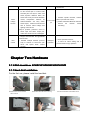
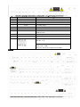
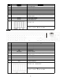
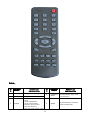
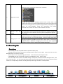
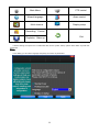
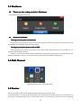
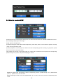
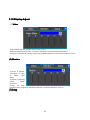
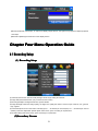
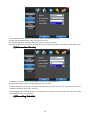
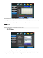
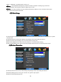
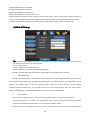
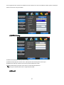
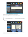
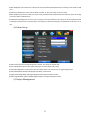
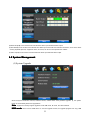
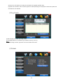
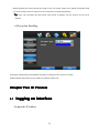
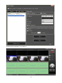
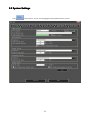
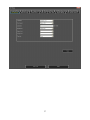
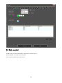
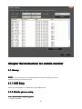
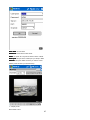
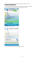
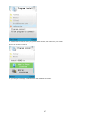
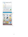
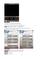
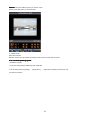
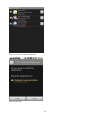
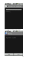
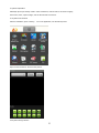
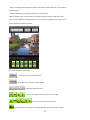
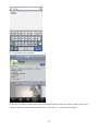
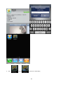
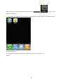
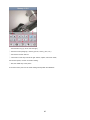
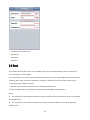
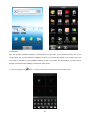
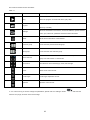
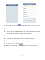
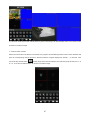
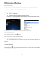
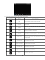
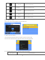
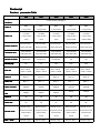
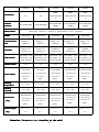
H.264 Standalone DVR _V2.02 USER MANUAL MANUAL_V2.02 INDEX .................................................................................... 3 Chapter one Products Introduce Introduce.................................................................................... ....................................................................................3 1.1 Technical Parameter........................................................................................................................... 3 1.2 Performance....................................................................................................................................... 4 ..................................................................................................... 5 Chapter Two Hardware Hardware..................................................................................................... 2.1 H.264 standalone 4CH/8CH/16CH/24CH/32CH DVR...................................................................... 5 ............................................................................................... 10 Chapter Three Operation Operation............................................................................................... 3.1Operation instruction.......................................................................................................................10 3.2 Powering On.................................................................................................................................... 13 3.3 Shutdown......................................................................................................................................... 15 3.4 Multi Channel.................................................................................................................................. 15 3.5 Preview............................................................................................................................................ 15 3.6 Recording operation...................................................................................................................... 16 3.7 Playback video................................................................................................................................. 17 3.8 How to control PTZ......................................................................................................................... 18 3.9 Alarm control................................................................................................................................... 19 3.10 Display Adjust................................................................................................................................20 .......................................................................... 21 Chapter Four Menu Operation Guide Guide.......................................................................... ..........................................................................21 4.1 Recording Setup............................................................................................................................... 21 4.2 Camera............................................................................................................................................. 23 4.3 Network Setup................................................................................................................................. 25 4.4 System Setup....................................................................................................................................29 4.5 System Management........................................................................................................................ 32 ................................................................................................. 34 Chapter Five IE Preview Preview................................................................................................. 5.1 logging on interface......................................................................................................................... 34 5.2 System Settings................................................................................................................................ 36 5.3 State control..................................................................................................................................... 38 .............................................................. 41 Chapter Six Instruction for mobile monitor monitor.............................................................. 6.1. Naway............................................................................................................................................. 41 6.1.1. DVR Setup............................................................................................................................... 41 6.1.2. Mobile phone setup.................................................................................................................. 41 6.2 Asee................................................................................................................................................. 61 6.2.1 Instructions of Android straight even version............................................................................ 62 6.2.2 Instructions of Blackberry ....................................................................................................... 68 6.2.3 Instructions of iPhone straight even version.............................................................................. 72 ................................................ 78 ................................................78 Chapter Seven FAQ (Frequently Asked Questions) Questions)................................................ 2 �... Power This DVR select the adaptor is DC12V; please make sure the power supply voltage before use the machine. If long time do not use the machine, please turn off the power of DVR machine, and let the electric plug away from power socket; �... safety This DVR only for indoor use, as for prevent short circuit or electric danger, please do not let the DVR in the raining or humid area. In case any solid or liquid inside the case of DVR, please turn off the power immediately, and ask the qualified technician check it before reboot the DVR; The DVR is the precision machine, there is nothing for repair by customers themselves in it, when it break down, please ask the qualified technician to check and repair, or contact with the agents of it. �... Installation Please keep the DVR in level for installation; Pay attention to equipment ground; For the first time to install the DVR, please make sure if the hard disk drive install or not; Prevent to open the case and change the hard disk drive in electrified; Propose to select the performance of hard disk drive will be 7200 rotating speed person second; Please select the appropriate installation site, so let the air can be free flow inside the DVR, prevent the machine overheating; Please do not install the DVR nearby the radiator, air chute etc. heat source, or where the direct sunlight, too much dust, or mechanical vibration or attack; Chapter one Products Introduce 1.1 Technical Parameter Compression standard H.264 baseline [email protected] Video iInput Composite 1.0Vp-p/75Ω,BNC×4/ BNC×8/ BNC×16/ BNC×24/ BNC×32 Video output Composite 1.0Vp-p/75Ω,BNC×1, VGA×1 Resolution Preview D1 704×576(PAL) ,720×480(NTSC) CIF 352×288(PAL) ,320×240(NTSC) Recording D1 704×576(PAL) ,720×480(NTSC) CIF 352×288(PAL) ,320×240(NTSC) Frate rate Preview/ recording 4ch 100fps(PAL), 120fps(NTSC 8ch 200fps(PAL), 240fps(NTSC) 16ch 400fps(PAL), 480fps(NTSC) 24ch 600fps(PAL), 720fps(NTSC) 32ch 600fps(PAL), 720fps(NTSC) Audio input -8dB~22k,RCAx4(4ch) Audio output -8dB~92dB,RCAx1 Audio decode ADPCM Alarm input Input low level alarm, user setting normal open or normal close, Varies according to the model 3 Alarm output 1ch output or 2ch output;Varies according to the model Recording mode Manual recording, timing recording , motion detection recording and external Simplex/duplex/ triplex triplex(recording, playback , LAN transmission) LAN RJ45(10M/100M self-adapting) PTZ control Yes Communication RS485×1,USB2.0×2 USB USB mouse control Hard disk drive 1or2or4x SATA(2TB or above) Remote control unit Yes Dimension Main board size : 220mm x 112mm Power supply AC110-230V alarm recording 1.2 Performance Turn-by-turn analog video output and VGA interface, according to TVmonitor or VGA monitor to live view Internal 1or2 or 3SATA interface, MAX in1/4/8/9/16/24/32or more video channel Real-time monitoring tomonitoring the recording streaming and the record file capacity in Every hours every channel, to presentation the status 2TB hard disk drive, the file of hard Storage function disk drive include cover mode circulation recording and none cyclical recording, the storage data to use the of video channel, recording, dynamic proprietary format, can not falsify the detection, video loss, monitoring lock-up. data, make sure the data safety. You can view the system log in local DVR. Video compression format:: H.264 Compression format Through USB interface to backup. ( for Support 8ch video and audio signal, video Backup function and audio maintaining stability in synchronous. example USB drive and mobile hard disk drive etc.) The video file can be downloaded by Client software through LAN to laptop hard disk drive. * through network to real time remote * Multiplex, to achieve real time recording monitoring; to be independent at the same time to * PTZ control single channel playback, research and * recording research and real time backwards, network monitoring, network playback; search download etc. * system setting parameter modify and * Multiple recording mode: Manual, the system software upgrade; Recording normal, alarm, linkage,dynamic detection and recording etc. turn-by-turn pre-recording playback function. function * Can playback the record file in DVR Network Operation function * remote monitoring alarm process and view the system log message; * to use embedded TCP/IP protocol and Embedded Operation System, can through network, to achieve quick-search access the DVR through client software the recording file and recording type, program bundle in the package; multiple playback type: SLOW, Fast *Management Model: use enhancement Forward, Backwards, step Forward. user management, password mode to Display the exact time of event occurred make sure the valid user to login the while recording file playback. system, flexible convenient and fast to set 4 the different permission user requirement. 8ch alarm input ( alarm event mode can be set normal open or normal close selection),and turn-by-turn video loss alarm, dynamic detection alarm, the alarm device may be smoke detection Alarm censer, temperature linkage detector.Possess function alarm output, 4ch detector, IR relay switch * Possess specific interface, achieve Com-munication port flexible convenient and fast to achieve alarm linkage and alarm input and PTZ control; * possess a standard Ethernet interface, achieve the network remote monitoring. lighting control at site. They’re possess protective circuit in Alarm input and alarm output port, make sure the device not to damaged. * Support PTZ decoder through RS485 communicate PTZ control * scalable multiple decoder protocol, Intelligent easy to achieve to control the pan operation driver and speed dome camera * mouse operation function; * In menu for same setting and to process shortcut copy operation function. Chapter Two Hardware 2.1 H.264 standalone 4CH/8CH/16CH/24CH/32CH DVR 2.1.1 Hard disk Installation For the first use, please install the hard disk 1 Remove the screws on both ○ 2 extracted from the next cover up ○ sides of shell 5 3 connect hard disk and mother board ○ 4 fix the screw of hard disk ○ 5 close cover ○ 6 install the screws on both sides of shell ○ 2.1.2 Rear panel 4CH Item Interface 1 VIDEO IN 4ch video input Description 2 AUDIO IN 4ch audio input 3 V-OUT 1ch video output 4 A-OUT 1ch audio output 5 VGA 6 NETWORK 7 USB 8 ON/OFF Power supply switcher 9 DC-12V Power adaptor port VGA monitor RJ45 for internet First USB for backup or upgrade system of DVR; Second USB for mouse 10 ALARM IN:1 2 3 4 alarm input port RS-485:A, B ALARM OUT: N1 alarm output port, every channel connect GND、OUT、COM; every two channel OUT, COM port is for GND; 8CH 6 Item Interface 1 VIDEO IN 8ch video input Description 2 AUDIO IN 8ch audio input 3 V-OUT 1ch video output 4 A-OUT 1ch audio output 5 VGA 6 NETWORK 7 USB 8 ON/OFF Power supply switcher 9 DC-12V Power adaptor port VGA monitor RJ45 First USB for backup or upgrade system of DVR; Second USB for mouse 10 ALARM IN:IN1-IN4 alarm input port RS-485:A , B ALARM OUT: N1 alarm output port, every channel connect GND、OUT、COM; every two channel OUT, COM port is for GND; 16CH 7 Item Interface 1 VIDEO IN 16ch video input Description 2 AUDIO IN 4ch audio input 3 V-OUT 1ch video output 4 A-OUT 1ch audio output 5 VGA 6 NETWORK 7 USB/ MOUSE 8 ON/OFF Power supply switcher 9 DC-12V Power adaptor port VGA monitor RJ45 for internet First USB for backup or upgrade system of DVR;Second USB for mouse ALARM IN:4CH 10 alarm input port RS-485:A, B ALARM OUT: N1 N2 for alarm output port, every channel connect C and O; port is for GND; 24CH Item Interface 1 VIDEO IN 24ch video input Description 2 AUDIO IN 8ch audio input 3 V-OUT 1ch video output 4 A-OUT 1ch audio output 5 VGA 6 NETWORK 7 USB/ MOUSE 8 ON/OFF Power supply switcher 9 DC-12V Power adaptor port 10 HDMI HDMI interface 11 TALK AUDIO TALKBACK VGA monitor RJ45 for internet First USB for backup or upgrade system of DVR;Second USB for mouse 12 ALARM IN:16CH RS-485:A, B alarm input port RS485-S A,B ALARM OUT: N1 N2 for alarm output port, every channel connect 8 C and O; port is for GND; 32 路机型 Item Interface 1 VIDEO IN 24ch video input Description 2 AUDIO IN 8ch audio input 3 V-OUT 1ch video output 4 A-OUT 1ch audio output 5 VGA 6 NETWORK 7 USB/ MOUSE 8 ON/OFF Power supply switcher 9 DC-12V Power adaptor port 10 HDMI HDMI interface 11 TALK AUDIO TALKBACK VGA monitor RJ45 for internet First USB for backup or upgrade system of DVR;Second USB for mouse 12 ALARM IN:16CH RS-485:A, B alarm input port RS485-S A,B ALARM OUT: N1 N2 for alarm output port, every channel connect C and O; port is for GND; 2.1.3 Alarm input port 8chanel alarm input, the mode of alarm input is no restriction (possible is normal open also normal close); the GND alarm detector connect to COM under parallel connection (the power of alarm detector supply by external power supply; the ground terminal of alarm detector join-up in parallel with DVR; the NC of alarm detector connect with the input end (alarm) of DVR; when you want to reset the remote alarm of triggered , the +12V power supply of alarm detector supply by DVR, for example, smoke detector. When you select the external power supply, please share the GND with DVR; Alarm input circuit: 9 Alarm inlet connection: 2.1.4 Alarm output port 4 way switching value alarm output, selectable in normally open contact, also selectable in normally closed contact, the external alarm device should be need Vcc; Chapter Three Operation 3.1Operation instruction 3.1.1 Remote control AND Front panel keypad 10 Table Table: S/ N pad KEYpad Name 1 【POWER】 2 【MENU】 3 【ESC】 Operating instruction S/ N Keypad Name 8 【 ENTER 】 【OK】 This button is used as“enter”and“ok” key in most circumstances 9 【PTZ】 Access/exit from PTZ control under preview state Power ON/OFF Access main menu Exit operation or enter upper menu Close soft keyboard Close current window Exit from current control Return to last menu Exit from PTZ control under 11 Operating instruction preview state 4 5 【 【 【 【 6 】 】 】 】 【 ▲.▼. ⊳ . �】 Slow playback,1/2×, 1/4×, 1/8× and single frame play Fast playback, 2×,4× and 8× playback Playback stop 【SEARCH】 【+/-】 Volume or number increase/reduction Select item of the list 11 【 ZOOM IN/OUT】 Lens control 12 【0~9 10+】 Digital input Corresponding; Channel is magnified in full screen under preview state 13 【FN】 Short cut 14 【 Switching of 1/4/8/9/16/24/32Preview mode 15 【ALARM】 】 Play / Pause Four-way to move the focal point in main menu, up and down to move in the normal window, to control pan driver to move in the PTZ control windows To mode of recording 7 10 Search for choosing playback 16 【CLEAR】 Alarm reset Clear alarm time 3.1.2 How to use mouse of DVR (for right hand mouse) To any function menu icon click the mouse left key into the menu To run the control point out operation Change again select frame or motion detection piece mode Click the assemble frame popping to pull down the list In the input frame, can select digit, character, lowercase, block letter, left click mouse on the keyboard of character input, that’s. ← say move back, _ say 1 Left key single click blank,Shift say switch case . 12 Right click mouse, popping the shortcut menu, as follows; 2 Right click mouse 。 Through the menu can be switching preview screen window mode, start replays, PTZ control. Four pictures playback mode, the point of the right mouse button, Can in a single picture, four pictures, eight pictures (8 road playback), 16 screen (16 road playback), twenty four picture,thirty two picture, broadcast control switch view show or hide broadcast control bar. 3 Double click left button To run the ActiveX Control ActiveX special operation, For example, double click the certain item of record listed file, then the system will playback the segment record video. Depress the left key and dragging the mouse, banding select Motion detection area, depress right key of mouse and Dragging, cancel the banding select area. 4 Dragging the mouse Dragging playback ProgressBar back and forth to dolly moves, to achieve the playback position adjustment. Dragging the audio and video regulation parameter bar dolly moves, to achieve the parameter adjustment. 3.2 Powering On Boot-strap If【POWER】pilot lamp off, please follow the operation step by step: First step: if the power does not plug into, please plug into the power, then the DVR begin to start, by now, if the DVR still inactive, to enter the next step; Second step: turn on the power supply of the DVR at the back panel, DVR begins to start. If【POWER】pilot lamp to offer RED, press the 【POWER】key, DVR begins to start. The video output mode of DVR ’s the default setting is multi picture channel mode after starting the DVR , if the time of start the DVR is in the Timing Recording Setting, the DVR will automatically to start the Timing Recording function, the corresponding channel’s recording pilot lamp will be light, the DVR is normal operation. Button Description Button 13 Description Main Menu PTZ control Wizard language Alarm control Multi channel Display setup Recording Control Playbake Exit Bake up If before starting, the system not to install hard disk, into the system, will tip: system didn't detect any hard disk connection! Note: In this dialog you can select language and quickly set various of parameters. 14 3 Shutdown 3. 3.3 � There are two safety mode for Shutdown Enter【Exit】,select【Power Down】. � Abnormal shutdown Through the rear panel to shutdown During the DVR running, directly to turn off the power through the rear panel power switch, please avoid as much as possible to do it. (specially while the DVR recording). Directly to pull up the power cable of DVR While the DVR running, directly to pull up the power cable of DVR, please avoid as much as possible to do it. (specially while the DVR recording). Caution: In some area, the power supply is irregularity, it will cause the DVR working not normal-operation, the DVR will be damaged in serious. In this surroundings, suggest select the stabilized voltage supply. 3.4 Multi Channel 1/4/8/9/16/24/32 preview screen mode switch 3.5 Preview After log in system of DVR, system will automatically directly enter the preview mode In the preview picture, you can see the overprint date, time, channel name, if the date and time is not correct show on the picture, re setting the date. There is a alarm input mode icon. (the meaning of every kind of icon as following 15 table) Channel picture attention 1 Channel is video when channel video pictures showed this symbol Channel 3 video happen cover when alarm Channel happen when dynamic 2 showed this symbol channel video pictures showed this symbol channel pictures test, 4 Channel open sound, the channel video pictures showed this symbol 3.6 Recording operation Customer can according to select the different kind of recording mode in this system. For the different kind of recording mode you set, the channel will be showed the mark on everyone channel. Manual recording ” permission. Note: Manual recording operational requirement the user should have “recording recording” Please make sure the hard disk drive has been installed and it has been formatted. Input manual recording operation menu 1)Input Single click right key of mouse or In main menu=> recording control can into manual recording operation menu. Under preview mode, press REC key or on the Remote controller unit key into recording control operation menu, as follows: 2) The explanation of manual recording operation menu 【manual recording】 Priority level highest, no matter currently what status of every channel, after carry out the manual press, corresponding channel will be record common in progress; 【 Auto recording 】 Setting channel recording by setting condition to record under Timing, Motion detection and Alarm in Recording Setting; 【Stop Recording】All video channel stop recording; 16 3.7 Playback video Button Description Button Synchronous/asynchronous play Description Voice adjustment 1/4/8/9/16/24/32 frame by frame screen(switch image) Speed slow Hide / display list Speed normal recording date Speed fast Play/pause/stop Sound off/on rewind Note: 1) During playback the Playback Tool will show the file playback speed, channel, timing, playback speed etc. information in the Playback control panel; 2) Can’t same time to select the Fast forward operation function in over 2 channel, only progress in anyone channel; 3) Can drag the Playback Speed toolbar by mouse; 4)In this dialog you can select the video precise to the second. 17 3.8 How to control PTZ 【Zoom】Lens in the current play far closer picture, use the mouse wheel also can undertake variable times control. 【Focus】Slight adjusting the focal length 【Iris】Aperture size adjustment 【Speed】Through the slider adjust rotation stepinterval, yuntai mainly used to control direction operation, the step length of turning the faster yuntai. 【Preset】Adjust the camera Angle, then direction and the corresponding input and clicking on [ set] button, preset dots to set the dots in the preset rastelli. Input presets dots and click on [Transfer] button, the camera will be transferred to the preset point corresponding position.Click[remove ] button, this presets dianjiang be cleared 【Set】Click 【Start Tour】 the trajectory of said no corresponding, click the 【 add Preset 】 and 【 delete Preset point 】, 【Clear Tour】 the cruise lines. 【Start Tour】begin to track record, was registered date 【 end Tour】,thus set up from the corresponding track circuit. 18 【Left Limit】Began to limit scanning Settings, was registered date 【 right Limit 】, thus set up corresponding limit scanning. 【Add Preset】Add presets point to the cruise lines. 【Delete Preset】Cruise lines from deleting preset points. 【Clear Tour】Remove the cruise line designated. Note: some equipment doesn't fully support all function, depending on the specific yuntai equipment and different. 【Control】PTZ Control 【Tour Scan】Point between cruise control. 【Pattern Scan】Track patrol control. 【PTZ Reset】Remove all Settings, original reset to the original state. 【Limit Scan】Yuntai boundary scan control around. 【Auto Pan】Remove the cruise line designated Note: some equipment doesn't fully support all function, depending on the specific yuntai equipment and different. 3.9 Alarm control 【Set Alarm】Selection need protection channel, click confirm corresponding channel after in protection status 【Clear Alarm】Remove protection condition, not alarm input to react 【Alarm Output】Open the corresponding alarm output 【All】Can choose all the channels 19 3.10 Display Adjust (1)Video 【Video Effect】Optional: standard, downy, sharp, custom. 【Default】Restoring default effect, for custom video effects, copy standard effect parameters. Through the slider fluctuation sliding, respectively adjustable brightness, contrast and saturation, tonal, etc. (2)Monitor 【 Device 】 Optional: VGA output, TV output etc display output device. 【 Default 】 Restoring default display parameters. Through the slider fluctuation sliding, respectively adjustable brightness, contrast and saturation, tonal, etc. (3)Setup 20 【Device】Optional: VGA output, TV output etc display output devices, the system may support multiple equipment and output. 【Resolution】Setting the resolution of the display device. Chapter Four Menu Operation Guide 4.1 Recording Setup (1) Recording Setup 【Channel】Choose the need to install passage "whole" says setting all channels. 【Image Size】CIF/HALF D1/D1 (only in whole function model) 【Encoding Mode】Including fixed bitrate, dynamic bitrate. 【Image Quality】Client-side image quality, the higher the quality the clearer. Choice scope: minimum, low, general, high, highest 【Frame Rate】Can click on the button manually input, 1 ~ 25 frames per second (PAL) or 1 ~ 30 frames per second (NTSC) continuous adjustable.【Audio】Can select close, open according to requirements 【Pre-Alarm Rec】Can select close, open according to requirements (2)Secondary Stream 21 【Channel】Choose the need to install passage "whole" says setting all channels. 【Image Size】CIF/HALF D1/D1 (only in whole function model) 【Image Quality】Client-side image quality, the higher the quality the clearer. 【Frame Rate】Can click on the button to undertake choosing, optional: automatic, 1FPS, 2FPS, 3FPS, 4FPS, 5FPS. (3)Information Overlay 【Channel】Choose the need to install passage "whole" says setting all channels. 【Channel Name】Can manual corresponding input channel's name 【 Channel Display 】 Can choose according to the requirements of users don't use, the top-left corner, left, lower, middle and downward, upper, right, and lower. 【Time Display】Can choose according to the requirements of users don't use, the top-left corner, left, lower, middle and downward, upper, right, and lower. (4)Recording Schedule 22 【Channel】Choose the need to install passage "whole" says setting all channels. Each longitudinal row of every seven days a week, said the 24 hours a day manipulated said, mouse the left key click on the small square footage, setting time to clean it has chosen right-click drag video time. 4.2 Camera When the system starts the camera will detect the format of video (1) PTZ Setup 【Channel】Choose regional channels, yuntai Settings "whole" says setting all channels 【PTZ Protocol】Yuntai equipment communication protocol It contains these options:Pelco_D1、Pelco_D2、Pelco_D3、Pelco_D4、Pelco_D5、Pelco_D6、Pelco_D7、Pelco_D8、 Pelco_D9、Pelco_P1、Pelco_P2、Pelco_P3、LILIN、MINKING、STAR、VIDO、NEON、DSCP、HY、N-control、 23 RM110、SAMSUNG,the default option is Pelco_D1. ★Note: yuntai parameter Settings every channel need after completion in Settings of gc1318 alone. 【PTZ Address】Yuntai equipment address, digital range 0 to 255. ★Note: here with the address must be consistent ball machine address, we can't control the ball machine. 【Bit-rate】Yuntai equipment baud rate. (2)Video Setup 【Video Mode】Provide PAL and NTSC both formats video formats choice, modify after you must restart your system can take effect. 【Channel】Choose to set the video Settings area passage "whole" says setting all channels 【Reserved Section】Click Settings enter. The white areas for privacy area 【Buzzer Alarm】Happen when video lost choice whether or not to allow buzzer warning 【Alarm Output】Happen when video lost upcoming linkage selected channel corresponding alarm output (3)Motion Detection 【Channel】Choose need to set up mobile testing area passage "whole" says setting all channels 【Sensitivity Setting】Can be set to give: minimum, low, general, high, highest 【Detection Area】Click Settings enter. 24 Green area for dynamic test, grey areas design.ferroconcrete-brick undefended area for. Press the mouse left key to drag on the lower detection area to the right, press the mouse button clearance. Detection area drag The save and exit button can save Settings, some give up and quit button abandon modification. 【Buzzer Alarm】Occur when dynamic test on the buzzer whether to allow the alarm 【Trigger Recording】That will happen when dynamic test on the linkage of selected channel fast ball trigger video 【Alarm Output】In this passage setting user can be copied to the other channels, fulfill the same dynamic detection alarm Settings 4.3 Network Setup (1)General Setup 【DHCP】After checked automatic assignment device will get IP address, subnet mask, the default gateway, the DNS server, etc 【UPnP】Can choose according to the requirement 【IP Address】Network logic address can according to the requirements set 25 【Subnet Mask】Server subnet mask 【Default Gateway】Server gateway 【DNS Server】DNS server addresses 【Server Port】Data port, initial socket for 7777 【HTTP Port】the default port for 80. If change, when using IE browser, need to monitor the IP address, adding new socket. If use IP address to 82, from the original browsing http://192.168.0.19, change for http://192.168.0.19:82. 【Handset Port】Network phones socket, initial socket for eight thousand eight hundred and eighty eight (2)Dial-UP Setup Tip: PPPoE dial-up successful, according to 【 PPPoE IP 】 shown on IP address, users can remote access hard disk video recorder. By nic LAN IP access. The dvr support model: Unicom:huawei E173,zhongxing MF100 Telecom:huawei EC150.huawei EC156.zhongxing MF583 “3G DIAL” have two modes with automatic and manual dialing, the operation follows as below. 1. Automatic Dialing Select the Automatic Dialing in the interface of the following picture, fill the right information according to the operator where the 3G card belongs to and the 3G referred guide, It includes IPS names, AP, dial-telephone, ID and password, the interface shows as the other following picture (some IPS once be chosen, the other relative information has been already done, so you needn’t fill any more, click “SAVE” directly). Then click “Save” directly. After having detected the 3G signal when DVR start, the system will dial up automatically. 2. Manual Dialing In the interface of following picture, users would fill the right information in the menu bar as same as Automatic dialing and click “SAVE”. Then click “Dial-up” after saving successfully (The referred information would be saved still after the DVR restart, but you should click “Dial-up” again). In these two modes, if the dial-up want success, first you should make sure that the 3G card is available. Since 26 the 3G signal has been existed, the related menu bar will show the correct IP address; if failed, system will popup a window to show the wrong information. (3)DDNS Setup 【DDNS Service】Dynamic DNS provider website 【DDNS Domain】Dynamic domain name, soft keyboard and hard keyboard can be input. 【DDNS Account】Login domain name service provider website user name 【DDNS Password】Login domain name service provider website password Tip: through the dynamic DNS server. Support dynamic DNS. (4)Email 27 【SSL Protocol】Sending E-mail in use safety network connection 【Test Email】Send an email to the recipient mailbox test 【Email Address】The recipient's email address. Users can input two different email address. 【Send Email】The sender email address . 【SMTP Server】Send mailbox mail server 【Email Account】The sender email address the corresponding account 【Email Password】The sender email address of the corresponding email password According to the customer request can be checked 【inputl alarm 】and 【 video loss 】 sending emails. Two can also choose. Note: your sender email must support SMTP. (5)Access Control 【List Rule】According to the requirement to choose: don't use, allow access, refused to visit. 【Starting IP】Display IP address started section 【Ending IP】Display IP address end segments 28 【Add】On the basis of the need for added 【Delete】According to the need to delete 4.4 System Setup (1)Time 【 System Language 】 Used in a remote remote device control more hard disk video recorder occasions, only in remote controls address and hard disk video recorder Numbers identical to remote operation. 【Device Number】According to the requirement to select the time zones, has twenty six time zone for user Settings. 【Time Zone】Select the format the date is displayed in including date, sun and moon June 21 years in three formats. 【Date Mode】To choose time display modes include 24-hour system and 12 hours to make 【System Date】The current system date 【System Time】The current system time 【Daylight-saving mode】According to the requirement to choose 【Set Time】Confirm modification system of time (2)HDD Management 29 【Disk Full】When video disk full system how to deal with, "said system will be automatic coverage the earliest video files continue covering video," stop video "says system to stop the current video. 【File Time】Says automatic generation video files interval, the set range 5-120 minutes. 【Recording Bit-rate】Said the total rate of current coding 【Recording Time】Said the storage devices systems installed in accordance with the current bitrate can store video of time. Display the current hard disk attributes: types, hard disk, usable capacity total capacity. Click [formatting ], all storage file will be lost. Tip: to format the hard disk before please stop system current all those videos. (3)User Management 【User】Characters in length up to 8 bytes, ignore trailing Spaces. Can be letters, Numbers, and other symbols. The user has the largest number of eight, user name may not be repeated. 【User Rights】According to the requirements set of functions need checked 30 【Add User】Input need to add user, and input the account password and passwords. According to save button to add user. 【Delete User】Select the users need to delete, and click on the "yes" button to remove users 【Edit User】Choose need to modify user, and in user permissions bar needed under the function of check. According to the save button modified users. 【Edit Password】Select the account, input to modify current user password, and enter the account password and confirmation password new. According to the save button for password changing. The password can be set to 0 ~ 8 bits (4)Alarm Setup 【Alarm Input】Choose corresponding alarm channel, "all" setup all channel said. 【Input Type】Alarm input to often open/closed type choice (voltage output style) 【Clear Alarm】Stop the current alarm video and alarm output, but not removal, can again trigger alarm. 【PTZ Relate】When will the linkage happened alarm yuntai control 【Trigger Recording】When will trigger happened alarm selected channel video. 【Alarm Output】When will the linkage happened alarm corresponding alarm output (5)Output Management 31 【Buzzer Output】In the chosen time intervals have alarm input will start buzzer output. 【Send Email】In the chosen time intervals have alarm input which will send relevant information, such as the alarm events, paparazzi pictures, equipment name, device ID, etc sent to user specifies the mailbox. 【Alarm Output】In the chosen time intervals have alarm input will start alarm output 4.5 System Management (1)System Upgrade Show the system hardware versions, software version, release dates. Click [software upgrade 】, the system began to automatically detect and upgrade file. Note: equipment currently support upgrades: local USB mode, IE mode, the client software. USB mode: former ensure USB device to connect upgrade normal, as upgrade program 32 has copy USB devices in the root directory. According to the interface can upgrade operation hints. Upgrade was successful, and the screen appears to restart operating hints. Equipment reboot after system that will enable the new software. (2)Log Search 【Date Search】Can search according to date 【Log Type】Optional: all, operation log, set diaries, alarm log, error log Note: according to the left, right arrow can move forward and content. (3)Default 33 Restoring default can restore selected according to need. The system restore to the default configuration state out, can according to the menu options choose to restore the corresponding Settings. Tip: menu color, language, time date format, video format, IP address, the user account, etc will not be restored. (4)Exception Handling 【Exception Type】Choose abnormalities: hard disk full, hard disk errors, network connection. 【Buzzer】When abnormality, choose whether to allow the buzzer hints. Chapter Five IE Preview 5.1 logging on interface To input the IP address 34 Pretermission IP address is 192.168.0.20 35 5.2 System Settings Point , As the picture ,You can set up language directory,After all to save you set. 36 37 5.3 State control In state control you can set reboot server, close server , remote to go up Remote upgrade: let PC file load in the system Log: to inquire sometime the server’s action 38 39 40 Chapter Six Instruction for mobile monitor 1. Naway 6. 6.1. Remark Remark: only the mobile phone with Windows Mobile and Symbian operating system can support the mobile phone monitor function. 1.1 6. 6.1 .1.. DVR Setup Please login MAIN MENU>>>>>NETWORK, setup MOBILE PORT: 2. Mobile phone setup 6.1. 6.1.2. 2.1 Windows Mobile Operating system 6.1. 6.1.2.1 1)Program download 41 Please copy the installation program whose name is amplayersetup.CAB from the attached CD to your mobile phone, the default save path is My Documents. 2)Click the program and start to install it, just select default path when it ask you to select install path. 3)Click install button to start to install. 42 4)After installed, click the Naway icon to run the program. 5)login the main interface as follow. 43 Channel Channel: select the channel you want to monitor. When you select a channel, it will connect to DVR automatically. Connect Connect: press it to connect to DVR. Setup Setup: Press it to enter into the interface to config the parameters for mobile phone monitor. Button definition definition: 【PTZ direction control(left、right、up、down)】;【area select(zoom in、zoom out)】;【focus (+、-) 】;【aperture(+、-)】;【snapshot】. Remark: Please make sure the parameters for PTZ in DVR is correct. Snapshot default save path is: Program>>>Naway>>>> photo 6)When you login for the first time, please setup the network parameters first, press setup to enter into the interface, as follow: 44 User name name: can be blank. Password: should be the same as IE. Sever Sever: the public IP or dynamoic domain name of DVR. Sever port port: this port is the mobile port you setup in DVR. Channel Channel: setup the default channel you want to check. Please press OK after you finished setup. 7)Display mode Normal/Full screen 45 Remark: Click screen can switch the display mode between normal and full screen. 2.2 Symbian Operating system 6.1. 6.1.2.2 1)Please copy the install program whose name is amplayersetup.CAB from the attached CD to your mobile phone, the default save path is memory card. As follow: 2)Click the program to install it. 3)You can select the install path you want as the follow picture . 46 4)Please select continue when you got the follow window, and make sure your mobile phone can access to internet. 5)you will got a message “install finished” after installed successful. 47 6)Please find the Naway icon in Application and run it. 7)when you login, you will find the window as follow: 48 Button definition definition: CH1 CH2 PTZ : up left zoom in + focus + aperture + CH3 CH4 PTZ :down right zoom out – focus – aperture – 【Play/Pause】 【Full screen/Normal】 【Snapshot】【Setup】【Exit】 Remark: Snapshot default save path is: "C:\Data\Images\” 8)When you login for the first time, please setup the network parameters first, press 【Setup】 to enter into the interface, as follow: Net Access point point: Please select the network, GPRS/EDGE/3G Sever address address: the public IP or dynamic domain name of DVR. Sever port port: the sever port is the mobile port you setup in DVR. User name name: can be blank. Password Password: the same as IE. 49 Channel Channel: setup the default channel you want to check. Please press Apply after you finished setup. 9)Display mode Normal/ Full screen Remark: Click screen can switch the display mode between normal and full screen. 2.3 Android Operating system 6.1. 6.1.2.3 1 Install the program 1. Copy the setup software P2PPlayer.apk to SD card. 2. Close USB, access to [Setting] — [Applications ] — [Application installer], and then the user can find the setup file: 50 Clue: Do you want to install this application? Press “Install” button. 51 If the installation is finished, the picture is as below: 52 2. System explanation P2PPlayer phone port mainly contain: video surveillance, channel switch, full screen magnify, PTZ control, focus, capture image, save as favorite and exit function. 2.1 System main interface After the installation, press“Naway” icon in the application, see the below picture: Open the main interface, see the below picture: 2.2 System setting interface 53 For the first time using or need to modify the parameters, press [Setting] button to access to the parameters setting. Favorite: The record which is saved can be found here; UserName UserName: The user name which is set on DVR [phone surveillance]; Password Password: The user password which is set on DVR [phone surveillance]; Server Server: The public IP address and dynamic domain name of DVR. Port Port: The server port which is set on DVR [mobile phone]. ChannelCount: Set the quantity of the channel. Default channel: Set the default channel which will do the video surveillance. RecordName: Save the name of the record. 54 ①After the setting press [Save] then it will go to the favorite folder. Next time you can find the record in the file. ②After the setting press [setting] and back to the front interface. After the setting, press “connect” button on the main interface and then it will connect the server. In this interface it can also switch the channel, full screen magnify, PTZ control, focus, phone capture and full screen display. The detail information is as below: :Press this icon to connect the server : Press this icon to open the setting interface : Switch the channel function. :It can control the PTZ move up, down, left and right. : It can operate the zoom, focus and iris. :Press it to enter into full screen mode, press it again back to the common mode. 55 :Capture the image function. 3 Familiar questions and their answers 1:Why it can not connect the server? a: Check the setting page layout, server, port, user name, password is right or not. b: Check the internet; check if the mobile phone is connected with the internet. 2:After enter into the main interface, why the user can not control the PTZ? a: Check if the channel has the PTZ. b: The reflection of the PTZ is too slow, please wait for a moment. 2.4 Iphone Operating system 6.1. 6.1.2.4 I. The installation of Aplayer 1. Open the icon“ 2. Click“ ”, the below image will appear: ” ,Input “naway” in the searching bar, click “ 56 ” the below image will appear: 3. Then the below image will appear: 4. After click the “FREE” on above image , the below image will appear, and the click “INSTALL”option, and the other image will appear. Input the password of Apple account , then click “ok”, 57 another image will appear. 5. After change to , it means it is downloading 58 Aplayer software and set it automatically. After the process bar “ ” of is full, it means it finishes the installation. 6.After finishing the installation, the interface of the mobile phone will appear Naway icon, like the below image. II. How to use APlayer 1. Click Aplayer icon, open the software. The introduction of the interface function is as below: 59 ① PTZ direction key (up, down, left and right) ② PTZ lens control (magnify+, reduce-),(focus+, focus-), (iris+, iris-) ③ Choose the monitor channel ④ The function of the key from left to right: Pause, capture, full screen mode, next monitor option, monitor connection setting. ⑤ Exit, the middle key of the phone 2. Set the monitor point: it is the same setting with Symbian and Windows. 60 ① IP address of the monitor point ② Network port ③ User name ④ Password 6.2 Asee This module has mainly instructions on the installation and usage in Android, Blackberry, iPhone mobile phone. 1) The acquisition of client software: The client software can be got from the CD material equipped with CD , then choose English and select the options supporting tools, finally choose the mobile phone monitoring or obtained from technical support. Each type of corresponding client software as follows. 1. Asee.apk: The smart phone monitoring client of Android operating system 2. ASee.cod & ASee.jdp: The smart phone monitoring client of BlackBerry operating system Notes: Ø The mobile phone client of apple mobile phone system (iOS)can be directly searched for ASee+ in the appstore and installed online. Ø The mobile phone client of Android system can be directly searched for ASee+ in the Android market and installed online. 61 2) The main functions of the program which is straight even version of current mobile phone monitoring are shown as follows: 1. Browsing real-time video function. In addition to BlackBerry, it can support four pictures at the same time preview. 2. PTZ control function (the controlled ball machine is in front). 3) The instructions of three platforms is shown as follows. 1. Android 2. Blackberry 3. iPhone 6.2.1 Instructions of Android straight even version 6.2.1.1 Essential condition 1) Support the version 1.5 or above of Android system. 2) Support DVR platform versions: Ø Hisilicon v1.0.1.8 and higher. Ø GRain v8.33 and higher. 6.2.1.2 Installation and operation instructions 1)Installation Support two installation modes and the user can choose one way for installation. 1. Install online Search ASee+ on google market and install online. As the below image shows: 62 2. Install offline Copy the Asee.apk installation package to Android phone through cable. In the specified directory find out the corresponding .apk, click the application installation (If there is not installed apk installer in the mobilke phone, the user needs to download an apk installation software so that it can identify the apk package), and there will be program icons after finishing installing. As the above image shows. 3)Click the program icon <Asee+>,the first screen after running is shown in the below image. 63 The functions of buttons show as follows: Table 1-1 Function keys Definition Function specification Play When the program connects with device, play video Capture the current screen(the default save path: the default pictures Capture directory of mobile) Set some information of the device, such as IP address, dynamic domain Settings name, port, username, password and device alias information. About Some device information of the software Previous group It can show the previous channels group. Next group It can show the next channels group. Choose one video channel of the device. And cooperate with "next Select channel group" can switch the 8 or 16 channels. PTZ control PTZ direction control including up, down, left and right. Zoom Zoom in/out control of PTZ. Focal length Focal length adjustment of PTZ. Aperture Aperture control of PTZ. 4)If it is first running or need to change the parameters, please click the <settings> button <Device List> page, as shown in the below image. 64 and enter the In <device list>interface, click <Add> button and enter <settings> interface, as shown in the above image Notes: Ø� Ø <DVR Title>:It is convenient to identify among multiple devices. �<Server>:The public IP address, dynamic domain name or LAN IP of DVR (The port should be mapping before using public IP and mobile phones need to open wifi before using LAN IP). Ø Ø� �<Port>:The mobile port set in DVR(default parameter is 8888). <User Name>:The username permitted to login the DVR(default username is ‘admin’). Ø� <Password>:The password of the user (default password is empty). Ø� <Max Channel>: The actual channel numbers of DVR. 5)After finishing, click <OK>and enter the Device List page. As shown in the below image 65 Notes: � � <Back>:Back to the screen of previewing image. <Channel List>:It shows the corresponding DVR and the default channel list, the user can arbitrarily choose a channel to preview image. � <Information Edit>:Click this button and enter the “Settings” interface, you can editor delete the device information, as shown in the above image 6)Complete settings, choose channel to preview, and the preview function include two modes: common mode and full screen mode. 1. Common mode is shown in the below image 66 2. Full screen mode is that when mobile phone lay down horizontally it will automatically switch to full screen mode, as shown in the above image 7)Channel switch function Select some channels in the Device List interface, the program will automatically switch to the Preview Interface and open the corresponding channel preview in Preview Interface. Program displays the default 1 ~ 4 channels, if the user clicks the channel button of Next Group in the Preview Interface, the channels group will switch to 5 ~ 8, 8 ~ 12, 12~16 and circulation switch. As shown in the below image 67 6.2.2 Instructions of Blackberry 6.2.2.1 Essential condition 1) Support the version 4.6 or above of Blackberry system, and mobile phone screen resolution is 480*360 and 480*320. Support 8900, 9000, 9700, 9630, 9900 of Blackberry. 2) Support DVR platform versions: � � Hisilicon v1.0.1.8 and higher. GRain v8.33 and higher§2.2 Installation and operation instructions 1)Install ASee. cod and ASee. jdp installation package into Blackberry handset through the desktop manager, as shown in the below image. 2)Click the options on mobile phone desktop and enter the interface of the above image. 3) <Asee> permission settings a. Click <application program> to find out <Asee>; b. Click the icon of <Asee> and enter the permission settings. c. Click <edit permissions>, set all permissions <permit>. Note:Some permissions can not be set <permit>( the gray options mean cannot change this option), and click “save”. 4)Enter the initial interface Click the program icon <Asee>, after running procedure there will be an welcome page, then enter the initial interface, as shown in the below image. 68 Notes: � � <Title>:It is convenient to distinguish between multiple devices. <Address> : The public IP address, dynamic domain name or LAN IP of DVR (The port should be mapping before using public IP and mobile phones need to open wifi before using LAN IP). � <Port>:The mobile port set in DVR(default parameter is 8888) � <Channel total>:The actual channel number of DVR. � <User ID>:The username owens view permissions of mobile phone(default username is admin). � <Password>:The mobile phone port of DVR (default password is empty). � <Network type>:Choose the network type that you need. � The corresponding functions of buttons show as follows: Function keys . Definition Function specification Enter the playing interface, and the program will connect with device and login begin to play video exit Device list Exit the program Enter the device list interface. 5) Click <login>, play the main interface, as shown in the below image. 69 The corresponding functions of buttons in <Main interface> show as follows: Function keys Definition Function specification Play When the program connects with device, play video Full screen Play full screen. Capture the current image (the default save path: the default pic Capture directory of mobile) About Some device information of the software. It can select the next channels group (1-4、4-8、8-16) or PTZ cont Next group Choose one video channel of the broadcasting device and select Select channel one of 8 channels. Up control of PTZ Down control of PTZ Left control of PTZ Right control of PTZ Zoom in The up direction control of PTZ. The down direction control of PTZ. The left direction control of PTZ The right direction control of PTZ The zoom in control of PTZ. 70 Zoom out The zoom out control of PTZ. Focal length + Amplify the focal length of PTZ. Focal length - Lessen the focal length of PTZ. Aperture + Amplify the aperture of PTZ. Aperture - Lessen the aperture of PTZ. 6) Exit the application program Click the button <Exit> and exit the program, as the below image shows. 7) Edit the <Device List> interface 1. Click the <Device List>and enter <Device List> interface, as shown in the above image. 2. Click the <menu> button and enter the <device edit> interface, as the below image shows. The corresponding functions of buttons in < device edit> interface show as follows: Menu definition Function specification 71 Set to real-time preview New Device When the program connects with device, play video. Create a new record. Edit Edit record. Delete Delete the selected record. Delete All Records Delete all records. Shutdown Shut down the program. 6.2.3 Instructions of iPhone straight even version 6.2.3.1 Essential condition 1) Support the version iOS 3.0 or above, and mobile phones includes iPhone, iPod, touch etc. 2) Support DVR platform versions: � � Hisilicon v1.0.1.8 and higher. GRain v8.33 and higher§2.2 Installation and operation instructions 6.2.3.2 Installation and operation instructions 1)Run the App Store program of iPhone Switch to the search tag page, and input Asee + in the search box to find the application installation package, then click <install> .After finishing installation, there will be Asee + program icon on the mobile phone desktop, as shown in the below image. 72 2)Click the program icon Asee+ and the initial interface after running procedure is shown in the above image. The corresponding functions of buttons show as follows: Function keys Definition Function specification Stop When the program disconnects with device, stop playing the video. playing Capture the current image (the default save path: the default pictures Capture directory of mobile). Set some information of the device, such as IP address, dynamic domain Settings name, port, username, password and device alias information. Channels group switch About It can switch to next channels group. Some device information of the software. Choose one channel video of the broadcasting equipment. And cooperate Select channel with "next group " can achieve the switch of 8ch and 16ch. PTZ control PTZ direction control including up, down, left and right. 73 Zoom Focal length Aperture Zoom in/out control of PTZ. Focal length adjustment of PTZ. Aperture control of PTZ. 3)Initial usage of need to change the parameter 1.Please click the settings button and enter the device manage interface, as shown in the below image. 2.Then select Add button and enter device add interface, as shown in the above image. Notes: � <Device Name>:It is convenient to distinguish between multiple devices. � <Address>:The public IP address, dynamic domain name or LAN IP of DVR (The port should be mapped before using public IP and mobile phones need to open wifi before using LAN IP). 74 � <Port>:The mobile phone port set in DVR(default parameter is 8888). � <User ID>:The username permitted to login the DVR(default username is ‘admin’). � <Password>:The password of the user (default password is empty). � <Max Channel>:The actual channel number of DVR. 3.After finishing, click <OK>, enter <Device Manage> interface. As shown in the below image. 4.In the <Device Manage> page, click the <back> button, enter the <add channel> interface, then click the <+> button , as shown in the above image. 5.Click the <+> button , and switch automatically to <Device List>, as shown in the below image. 75 6.Click the button to view all channel numbers, as shown in the above image. 7.Double click any channel, then switch to the <channel preview> interface to preview channels, it can support four channels previewing at the same time, as shown in the below image. 8.Click the <settings> button enter the <Device Manage> interface, as shown in the above image. The user can edit, modify and delete device information by clicking the corresponding icon or slipping the item. (1)Click the <edit> button enter <parameter modifying> interface, as shown in the below image. 76 (2)Slide rightly the <edit> button to delete the information. As shown in the above image. 4)Video display mode There are two modes: common mode and full screen mode Switch: when the mobile phone lay down horizontally it will automatically display full screen. common mode full screen mode 5)Channel switch function Select some channels in the Device list interface, the program will automatically switch to the Preview Interface and open the corresponding channel preview in Preview Interface. Program displays the default 1 ~ 4 channels, when 77 elected the channel <Channel switch> button in the <preview interface>, the channels group will switch to 5 ~ 8, 8 ~ 12, 12~16 and circulation switch. As shown in the below image. Chapter Seven FAQ (Frequently Asked Questions) 01:Why the DVR did not run after connect the power supply? ①Please check the power switch turn on or off at the rear panel of DVR. ②Please check if the turn on DVR operation correct or not? ③If you select the adaptor +12V, 5A or above? (8ch 5A, 16ch 220V 200W) 02:Still stop over on the boot-strap frame? Physical damaged in hard disk drive Boot manager abnormal. 03:Why does appear the boot running too slow? ①There are too much capacity data in hard disk drive, the system will automatic search the data when the system boot up, caused the boot running slow. ② The hard disk drive error will cause the system research the data repeatedly, caused the boot running slow. 04:Why does the system reboot repeatedly? ①Check the hard disk drive, if there is not the FAT32 formatted in it or the problem in it and caused the DVR reboot; ② Please check the power supply of DVR, if you installed a lot of hard disk drive, it may be reboot 78 repeatedly underpower; ③ Please pull up the network cable, then to check the DVR can work normally or not, being the catastrophe failure in network, it will cause the DVR reboot repeatedly; 05:Why does the system halted of DVR during the playback and search the video file information in progress? Please check if you install the hard disk drive or if the drive is ok or not? Please replace the good one for it soon; If the ambient temperature on the high side or not? Is there any heaven current installation surrounding and external video device, heavy current surging video cable, caused the DVR can not work properly and the system halted; 06:Firmware upgrade failure? U drive is not good compatible with the DVR, cause the DVR can not detected it, suggested to try one or two more different kind of U drive in the market; USB interface is not good; The voltage hunting fearfulness during the system firmware upgrade in progress; 07:Why the display color is black and white in TV and VGA monitor? Check the video system is it matching the video input, DVR, TV or VGA monitor, if there is not on all fours, please set the video system mode in auto automatic recognition; 08:Why does nothing display on the TV or VGA monitor? ①please make sure if the power supply of TV or VGA monitor turn on or not; if the illumination located in the lowest status? ②if the video connected with TV or VGA monitor properly? Check if there is any video signal input? And make sure the line faulty or not? 09:Why does the video like water wave, to appear obstruction distortion? ①if there is short circuit, open circuit or insufficient solder and connection failure of video cable? ② If the video cable obstruction by high voltage interference, please separate the video and high voltage in linkup cabling, at the meantime, please select the better quality, shield video cable for the project; ③In the whole system, only select the central point to grounding, please do not multi port to grounding, then, cause the common mode obstruction, please connect the screw in DVR rear panel to grounding; ④Check if there is the become old problem in the camera or TV monitor and cable? 10:Why do the color of live video and record video data distortion? ①Make sure the input and output video parameter of main menu setting correct; ②Make sure the connection is correct; 11:Why does the video skew became deformed, color cast? ①Make sure the VGA cable and DVR be connected with grounding properly; ② The DVR working atmosphere temperature high, or no good in radiating, cause the VGA chipset working exceptional, or the mention circuit parameter is abnormal; 12:Why does the record video playback in mosaic under local DVR? ①The recording parameter setting is too low cause the record video quality overall down, sometime appears to mosaic; ②The record video file locates where there is a bad sector in a hard disk drive, it will cause the mosaic raising; 79 Postscript Product parameter Table 4CH 8CH Compress Video out Picture standard 24CH 32CH H.264 baseline [email protected] standard Video in 16CH BNC BNC BNC BNC BNC (1.0Vp-p/75Ω) (1.0Vp-p/75Ω) (1.0Vp-p/75Ω) (1.0Vp-p/75Ω) (1.0Vp-p/75Ω) 1TV BNC 1TV BNC 1TV BNC 1TV BNC 1TV BNC (1.0Vp-p/75Ω)/ (1.0Vp-p/75Ω)/ (1.0Vp-p/75Ω)/ (1.0Vp-p/75Ω)/ (1.0Vp-p/75Ω)/ 1VGA 1VGA 1VGA 1VGA/1HDMI 1VGA/1HDMI PAL(704×576), PAL(704×576), PAL(704×576), PAL(704×576), PAL(704×576), NTSC(720×480) NTSC(720×480) NTSC(720×480) NTSC(720×480) NTSC(720×480) 1024x768/800x 1024x768/800x 1024x768/800x 1024x768/800x 1024x768/800x 600/1280x1024 600/1280x1024 600/1280x1024 600/1280x1024 600/1280x1024 D1/HD1/CIF D1/HD1/CIF D1/HD1/CIF CIF CIF 4ch 8ch 16ch 24ch 32ch PAL:1~25P/S; PAL:1~25P/S; PAL:1~25P/S; PAL:1~25P/S; PAL:1~25P/S; NTSC:1~30P/S NTSC:1~30P/S NTSC:1~30P/S NTSC:1~30P/S NTSC:1~30P/S Audio in RCA×4 RCA×8 RCA×4 RCA×8 RCA×8 Audio out BNC×1 BNC×1 RCA×1 BNC×1 BNC×1 Audio encoded ADPCM ADPCM ADPCM ADPCM ADPCM 32Kbps 32Kbps 32Kbps 32Kbps 32Kbps Alarm In 4E 4E 4E 16E 16E Alarm Out 1ch 1ch 1ch 2ch 2ch on ratio resoluti resolutio Record encoded Record play Roll rate Audio encoded rate Record mode Mult mode Manual record, Manual record, Manual record, Manual record, Manual record, motionrecord and motionrecord and motionrecord and motionrecord and motionrecord and externa alarm externa alarm externa alarm externa alarm externa alarm record record record record record Record,Play, Record,Play, Record,Play, Record,Play, Record,Play, 80 Hd interface Network interface Internet Internet Internet HDMI: HDMI: HDMI: No No 1080P(1920*108 1080P(1920*108 1080P(1920*108 0) 0) 0) RJ45(10M/100M/ RJ45(10M/100M/ RJ45(10M/100M/ 1000M) 1000M) 1000M) RJ45(10M/100M) Mobil platform RJ45(10M/100M) Internet Internet Naway.CAB;symbian v3;symbian v5;Naway-Android;iphone,Blackberry RS485 PTZ control PTZ control PTZ control PTZ control PTZ control Communication RS485×1, RS485×1, RS485×1/2, RS485×1/2, RS485×1/2, USB2.0×2 USB2.0×2 USB2.0×2 USB2.0×2 USB2.0×2 port Hard Disc USB interface Remote control Power adapter Working temperature Working humidity Product size mm (mm mm) Product weight Kg (Kg Kg) SATA×1/2 SATA×1\2 2/4/8SATA 2/4SATA 2/4SATA (maximum 2T) (maximum 2T) (maximum 2T) (maximum 2T) (maximum 2T) Usb mouse,Usb disc backup、usb mobile hard disk Usb mouse,Usb disc backup、usb mobile hard disk Usb mouse,Usb disc backup、usb mobile hard disk Usb mouse,Usb disc backup、usb mobile hard disk Usb mouse,Usb disc backup、usb mobile hard disk Yes Yes Yes Yes Yes 12V/3A DC 12V/3A DC 12V/5A /6ADC 12V4A/5A /6ADC 12V4A/5A /6ADC ( according to ( according to ( according to ( according to ( according to the sum of the sum of the sum of the sum of the sum of DISK) DISK) DISK) DISK) DISK) 0℃~+60℃ 0℃~+60℃ 0℃~+60℃ 0℃~+60℃ 0℃~+60℃ 10%~90% 10%~90% 10%~90% 10%~90% 10%~90% 330x250x50mm 330x250x50mm 380x300x55mm ( according to ( according to ( according to the sum of the sum of the sum of 440*360*70mm 440*360*90mm ( according to ( according to the sum of the sum of DISK) DISK) DISK) DISK) DISK) 2.6(without 2.6(without 3.0(without 3.46(without 3.52(without disc) disc) disc) disc) disc) Attention:Parameters vary depending on the model 81 PRODUCT WARRANTY CARD All the products sold are covered by 12months warranty from the date of invoice. Warranty instructions: 1. Please contact us when the product is caused by its own fault within 1year warranty. 2. Please mail us your written warranty card as soon as possible after purchasing our products so that we can repair or replace this product to its original operation condition. Or the company will not deal with it. 3. Please write the truth on the warranty card. 4. Paid for repairing as follows: A: Equipment failure caused by human operation B: Equipment failure caused by not conforming to the using environment C: No warranty card D: Warranty expired Product model Purchasing time Product serial number User name Contact person Telephone Please keep the warranty card for the better service. Note:Please 82


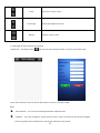
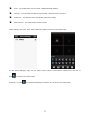
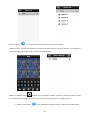
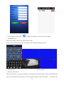


![Manual de utilizare[DOWNLOAD]](http://vs1.manualzilla.com/store/data/005723533_1-258331d4abba7698d1081b2119c4c2bf-150x150.png)