1
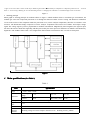
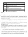
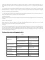
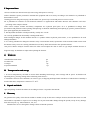
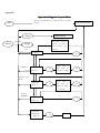
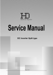
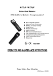
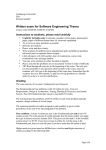
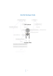
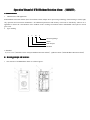
200905
23
Operation Manual of JCB4 Methane Detection Alarm (200905
20090523
23)
A. Summarization
1. Characteristics and application
JCB4 Methane Detection Alarm (short for methane alarm) adopts micro-processing technology characterizing in small, light,
easy operation and convenient maintenance. All calibration parameters and linearity correction are finished by software. It is
applicable to detect the concentration of the methane in the working environment where inflammable and explosive mixed
gases exist.
2. Type marking
J
C
B
4
Measuring Range
Alarm
heat catalysis
Methane
3. Standard
AQ 6207-2007《Portable Carrier catalysis Methane Detection Alarm》、Q/SD 021-2008《JCB4 Methane Detection Alarm》
B Working principle and Structure
1 The structure of JCB4Methane Alarm is as below figure 1.
1.Upper cover 2.PVC mask 3. Power switch key 4. Mouth of gases mark 5. Thermocatalysis component 6. Component protection cover
7.. Circuit
board 8. Lower casing 9. Battery pile 10. Current-limiting resistor 11. Charging bolt 12. Buzzer 13. Nixietube display screen 14. Fast fuse
Figure 1
2 Working principle
Block graph of working principle for methane alarm see figure 2. While methane alarm is in methane gas environment, the
methane gas enters into component protection cover through the transom window of lower casing. The flameless combustion
occurs on the surface of the component inside the protection cover (carrier catalytic components), therefore its resistance value
increases. The Wheatstone bridge composed of carrier catalytic components and resistor loses balance and outputs voltage
signal. The voltage signal is positive proportional to methane concentration. Magnified by linear magnifier, the signal is input
into the A/D converter inside the singlechip, and then processed by the micro-processor and shown as methane concentration by
digital tube. The methane alarm emits voice & light alarm while methane concentration value exceeds set alarm point.
Figure 2
C Main specifications (See Table 1)
Table 1
Item
Measuring
range
Tolerance
Alarm point
Response
time
Resolution
Carrier
catalytic
element
Specification
(0.00~4.00)%CH4
Detecting
range
0~1.00
1.00~3.00
3.00~4.00
Allowed
tolerance
±0.10
True value ±10%
±0.30
Set at will in(0.50~2.5)% CH4 (Original set 1.00%CH4)
≤20s
0.01%CH4
Working voltage of Carrier catalytic element is 2.8V,Working current ≤100mA
1
Display mode
3-digital LED
Battery pack
AA type 1800mAH 、 3.6V Ni-Mh Battery pack ( inside connect 1.5Ω/16W
current-limiting resistance in series)
over
range
methane
impact
protection
When concentration of methane is ≥4.50%,nixietube
shuts off automatically after the buzzer alarm once.
Low voltage
alarm
When the battery voltage lower than 3.3V, alarm lamp twinkling , When the battery
voltage lower than 3.1V , the methane alarm shuts off automatically after the buzzer
alarm once.
Explosion
protection
Dimensions
twinkling、the methane alarm
Intrinsically safe and flameproof for mining,explosionproof mark ExibdⅠ
101×51×23mm
Weight
<0.2kg
Working
conditions
1、Working temperature:(0~40)℃;2、Relative humidity:≤98%(at 25℃);
3、Air pressure:(68~116)KPa;4、Wind speed:
(0~8 )m/s;
5、Underground coal mine with explosive gases.
D. How to use
1 Function key-press
Key-press distribution as Figure 1 and its function is as below:
1)“On/off” key: Press it for a while when the detector is under shutdown mode, then the detector open up. Press it for a while
when the detector is under open up mode but not setting mode, then the detector close down. When the detector is under setting
mode, this key is used as data degression key.
2)“Voltage” key: To press this key to show battery voltage when the detector is under openup mode; and it is used as increase
key when the detector is setting ,adjusting.
3)
“Setting” key: Press “voltage” and “setting” for 3 seconds when the detector is under open mode, then the detector turns into
setting mode. It is used as confirming key when the detector is setting and adjusting.
2 System setting and adjustment: (See appendix: Operation diagram of system Menu)
Before setting or adjustment, the detector should be open up for 10 minutes preheat or under stable state.
1)Zero adjustment: Press “voltage” and “setting” key for 3 seconds at the same time, the detector enters into setting state and
the digital tube shows “1”. Then confirm the setting, adjustment finishes when hearing a sound.
Note: The process of zero adjustment should be taken in clean air. It is prohibited to adjust zero when the air cleanliness does not meet requirements
and the digital tube will show “ERR”.
2)Calibration: Under setting state, to adjust by using “Voltage” or “On/off” key till the digital tube shows “2”, then confirm by
pressing “setting” key, and the detector enters into calibration state when hearing a sound. And here the value shown in digital
tube is the one set last time. To adjust a value of this time by using “Voltage” or “On/off” key, confirm by pressing the “setting”
key to back setting state.
Note:
1. The calibration should be taken after standard gas enters into stability. The flux of standard gas sample should be 200ml/min.
2. It must be, for the adjusted value, the same as of standard gas sample, otherwise the measuring accuracy would be influenced.
3. It is prohibited to take calibration before input standard gas sample. If wrong operation is taken, please recover it as per clause 4 “recovery
setting:”.
3)Setting alarm point: Under setting state, to adjust by using “Voltage” or “On/Off” key till the digital tube shows “3”, then
confirm it by pressing “Setting” key and the detector enters into alarming point setting mode after hearing a sound. Here the
value shown in digital tube is the one adjusted last time. To adjust the value to the needed setting by using “Voltage” or
“On/Off” key, then confirm it by pressing “setting” key and exit the alarm point setting mode to the setting mode..
2
4) Recovery original setting: Under setting state, to adjust by using “Voltage” or “On/Off” key till the digital tube shows “4”,
then confirm by pressing “setting” key, and all the parameter of the detector recover as it is leaving factory after hearing a
sound.
5)Exit setting state: After all parameter adjustment finishes and back to setting mode, to press “Voltage” or “On/Off” key till
the digital tube shows “0”, then press “setting” to confirm it. It exits the setting state when hearing a sound and here the digital
tube shows concentration value of present methane.
6)Under setting state, the detector will automatically enters into methane measuring state if no any operation is taken over 5
minutes. The digital tube shows concentration value of present methane.
3 Methane measurement
When it is opened up, the detector enters into methane measuring state automatically and digital tube shows concentration value
of methane.
4 Battery voltage measurement
Under opening state, to press the “Voltage” key for a while, the digital tube shows battery’s voltage. To loose it, 0.5 seconds
later the detector will enters into methane measuring state automatically.
5 Charging.
There is specific and intelligent charger to charge up the detector and the charging process is automatic. To plug the charger into
AC 220V when it need to be charged, the indicating light turns into orange, showing the power supply is connected. Then put
the detector block into the charger slot, the indicating light turns into red, showing the charging process begins. It is charged full
when the indicating light turns into green.
E. Ordinary faults analysis and debugging (See table 2)
Table 2
Faults phenomena
Cause analysis
Solutions
Over low voltage or ineffective for the
battery.
To charge or replace the battery.
Unable to open
Poor contact for the battery.
Unable to adjust zero
the reason.
There is combustible gas in the
air.
Put the
clean air.
Failure on key-press.
Replace a thin film switch
There is sound but no light
LED damaged
while alarming.
detector
into
Replace the LED
There is light but no sound Buzzer damaged
while alarming.
Time of continuous work is Insufficient battery. capacity
less than 9 hours.
Aged battery.
Decline of resolution
To re-weld it after finding out
Replace the buzzer
Recharge the battery.
Replace the battery.
Aged carrier catalytic element or Replace the carrier catalytic
poisoned
element.
3
F. Important hints
1.Please read this user manual seriously before using, and operate it correctly.
2.There should be specific personnel to maintain the equipment and use it strictly according to user manual. It is prohibited to
disassemble it at will.
3.During period of using and carrying it in the leather coat, please keep it clean and protect it from severe hit..
4.It is prohibited of existence of such chemical substance as organosilicon and binder. Because such substance will cause
poisoning of the catalytic element.
5.The carrier catalytic element and battery components are explosion proof parts. So it is prohibited to change their
specification and parameter while repairing and replacing. It should be maintaining and replacing by specific personnel and use
spare parts supplied by the manufacturer.
6. The adjustment should be carried periodically, usually once a week.
7.It is strictly prohibited to disassembly it underground mines.
8.The intelligent charger for the methane detector is a product without explosion proof feature, so it is prohibited to be used
underground mines.
9. It is strictly prohibited to change the intrinsic safety circuit and the model, specification of the elements which concern with
the intrinsic safety circuit. It is strictly prohibited to use battery which not include in the operation manual.
10.It proves that the catalytic element end its life when can not adjust the value as same as type sample methane because of
long term usage. It should be re-adjust after replacing the element.
G. Whole set
1 Methane detection alarm
2 Leather coat
3 Charger
4 Operation Manual
1pc
1pc
1pc
1pc
H. Transportation and storage
1. It can be transported by all kinds of means which including land-carriage, water carriage and air parcel. It should avoid
impacting, heavy pressing, raining and avoid mixing with corrosive.
2. It should be stored in well ventilation, no corrosive gas, no dropping and liquid attack warehouse of which relative humidity is
no more than 90%, temperature is between 0℃~40℃.
I. Unpack and check
Open the package to check the whole set according to Clause 7 required in this manual.
J. Warranty
We guarantee the quality of the detector within 12 months (except for the carrier catalytic element) from the date when it is sold
and would be responsible to repair it free in charge for any non-man-made damage during the period (except for any damage
from force majeure, e.g. natural disasters, war, etc).
Manufacturer reserves the rights to change content of manual operation.
4
Appendix:
Operational diagram of system Menu
Open up and automatic self inspection after 3 seconds
Concentration display
pressing
On/of
f
Voltage
Voltage display
3s pressing
Setting
Shows ERR, because the
Voltage
cleanliness in air doesn’t
meet
requirements,
stop
adjust zero
zero
show“1”
set
Show
Calibration
Voltage
key
last
set
Shows“2”
设
value
time.
of
To
set
adjust by voltage
Alarming point
setting
Voltage key
Show
set
Shows “3”
last
b)
value
time.
of
To
set
a)
adjust by voltage
↑or On/off↓
recover
defaultin
Voltage key
set
Shows “4”
c)
Voltage key↑
On/Off key ↓
Exit
set
Shows“0”
设
5