1
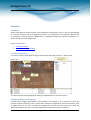
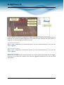
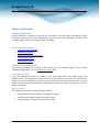
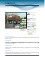
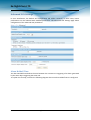
Ex-Sight.Com LTD
VA2 Series
VCA user's Manual
Ex-Sight.Com LTD
Table of Contents
Introduction ............................................................................................................................................ 5
Getting Started........................................................................................................................................ 6
Getting Started........................................................................................................................................ 6
VCA Feature Packages............................................................................................................................. 7
Accessing VCA Configuration .................................................................................................................. 8
Activation ................................................................................................................................................ 9
Activation ............................................................................................................................................ 9
Obtaining an Activation Code ............................................................................................................. 9
Applying an Activation Code to a Unit .............................................................................................. 10
Enabling VCA ......................................................................................................................................... 12
Switching VCA On and Off................................................................................................................. 12
Enable VCA .................................................................................................................................... 12
Object Tracking ............................................................................................................................. 12
Counting Line ................................................................................................................................ 12
Enabling Metadata Streaming .......................................................................................................... 13
Configuration of Zones and Rules ......................................................................................................... 15
Configuration of Zones and Rules ..................................................................................................... 15
Tracking Display ............................................................................................................................ 15
Properties Inspector...................................................................................................................... 15
Event History ................................................................................................................................. 16
Customizing the Tracking Display ..................................................................................................... 16
Display Blobs ................................................................................................................................. 17
Display Objects in Multiple Colors ................................................................................................ 17
Display Non-Alarmed Objects ....................................................................................................... 17
Display Object Height.................................................................................................................... 17
Display Object Speed .................................................................................................................... 17
Display Object Area ....................................................................................................................... 17
Display Object Classification ......................................................................................................... 17
Creating Detection Zones and Lines ................................................................................................. 17
Creating a Zone or Line ................................................................................................................. 17
01A.02
Ex-Sight.Com
1
Ex-Sight.Com LTD
Editing Zones and Lines................................................................................................................. 18
Adding and Removing Nodes ........................................................................................................ 19
Non Detection Zones ........................................................................................................................ 19
Detection Rules ................................................................................................................................. 20
Detection Rules ............................................................................................................................. 20
Object Presence ............................................................................................................................ 21
Object Direction ............................................................................................................................ 22
Object Enter and Exit .................................................................................................................... 22
Object Appear and Disappear ....................................................................................................... 23
Object Dwell .................................................................................................................................. 24
Object Stopped ............................................................................................................................. 25
Object Class ................................................................................................................................... 25
Object Tailgating ........................................................................................................................... 26
Object Speed ................................................................................................................................. 29
Counting Line ................................................................................................................................ 30
Counters ................................................................................................................................................ 36
Counters ............................................................................................................................................ 36
Creating Counters ............................................................................................................................. 36
Assigning Rules to Counters .............................................................................................................. 36
Incremental Counters ................................................................................................................... 37
Decremental Counters .................................................................................................................. 37
Occupancy Counters ..................................................................................................................... 37
Camera Calibration ............................................................................................................................... 38
Camera Calibration ........................................................................................................................... 38
Camera Calibration Topics ............................................................................................................ 38
Calibration Page Elements ................................................................................................................ 38
3D Graphics Overlay...................................................................................................................... 38
Mouse controls ............................................................................................................................. 38
Other Graphical Tools ................................................................................................................... 39
Calibrating a Camera ......................................................................................................................... 41
Step 1: Find some people in the scene ......................................................................................... 41
01A.02
Ex-Sight.Com
2
Ex-Sight.Com LTD
Step 2: Adjust tilt angle and camera height .................................................................................. 42
Step 3: Verify the setup ................................................................................................................ 43
Tip: If it all goes wrong .................................................................................................................. 44
Advanced Calibration Parameters .................................................................................................... 44
Vertical Field of View ........................................................................................................................ 45
Measurement Units .......................................................................................................................... 45
Object Classification.............................................................................................................................. 47
Object Classification.......................................................................................................................... 47
Advanced VCA Settings ......................................................................................................................... 49
Alarm Holdoff Time ........................................................................................................................... 49
Measurement Units .......................................................................................................................... 51
Metadata Format .............................................................................................................................. 51
Event ............................................................................................................................................. 51
Object ............................................................................................................................................ 51
Counting ........................................................................................................................................ 51
Do not send empty metadata packets .......................................................................................... 51
Blob ............................................................................................................................................... 51
Counting Line Diagnostics ............................................................................................................. 51
More Information ......................................................................................................................... 52
Stationary Object Hold-on Time ....................................................................................................... 52
Tracking Options ............................................................................................................................... 52
Minimum Tracked Object Size ...................................................................................................... 52
Display Options ................................................................................................................................. 52
Minimum Alarm Object Display Time ........................................................................................... 52
Minium Object Display Time ......................................................................................................... 52
Restore All Default Settings .............................................................................................................. 52
01A.02
Ex-Sight.Com
3
Ex-Sight.Com LTD
Introduction
VCAsys is a real-time video analytics engine that utilizes advanced image processing algorithms to
turn video into actionable intelligence. At the core of the product is an advanced object tracking
engine that continually tracks moving and stationary targets. The tracking engine features built-in
robustness to environmental nuisance conditions such as changing illumination, moving foliage,
rippling water, etc.
VCAsys is a generic name for a suite of analytics products that include:
•
VCApresence: continually tracks moving and stationary targets and generates real-time
alerts of object presence in multiple overlapping detection zones.
•
VCAsurveillance: continually tracks and classifies moving and stationary targets and features
a full suite of rule-based filters including: enter, exit, appear, disappear, stopped objects,
directionality constraints, object counting, loitering, object type and object speed. Multiple
filters are supported on any combination of multiple overlapping detection zones.
•
A full range of packages: optimized for specific scenarios. See the VCA Feature Packages
topic for detailed information about the packages available for different platforms.
Using the intuitive web-based configuration application, it's possible to quickly and easily define
rules that generate real-time alerts when triggered. The alerts are available in all formats supported
by the hardware on which it is enabled.
This user guide will help you get VCAsys configured for your application quickly, as well as lead you
through some of the advanced features provided by the product.
01A.02
Ex-Sight.Com
5
Ex-Sight.Com LTD
Getting Started
In order to get up and running as fast as possible, the following steps should be executed:
•
Locate a unit that supports VCAsys and ensure it is upgraded to a firmware version that
contains the VCAsys engine.
•
Obtain an activation code for the feature set required. The different feature levels available
for different platforms are described in the VCA Feature Packages topic.
•
Connect power, network and input video.
•
Activate the VCAsys engine.
•
Calibrate the unit [VCAsurveillance only].
•
Configure the detection rules.
•
Configure the alert output format.
01A.02
Ex-Sight.Com
6
Ex-Sight.Com LTD
VCA Feature Packages
VCA functionality is available in a range of different packages and on different platforms. The license
types available for IP and PC platforms are listed in the following table.
IP Analytics
camer
Full filter
Number
Surset +
a
of
Tamp
shake veillanc Presenc abandon
detectio er
elime filter ed and
e
n zones detect
inatio tracker
removed
or lines
n
object
Imag
Class and
Directio Tail- On- Obje Peopl
PTZ
e
speed
n & gatin screen ct
e Counti Auto- stabil
filters +
Comment
dwell
g counte Meta track ng Line trackin calibrati
filters filter rs
g izatio
data er
on
n
Inclusive licenses - included with hardware
VCApresIP
40
√
√
Special function licenses
VCAcountI
P
40
VCAaccess
IP
40
VCAdetect
IP
40
√
√
√
√
√
√
√
√
Bidirectiona
l counting
in busy
areas
Tailgating
detection
using
Counting
line
Outdoor
surveillan
ce
reduced
filter set
√
Full licenses
VCAsurvIP
40
√
√
√3
√
√
√
√
Optimised
for
outdoor
surveillan
ce
√
3
Except abandoned/removed object
01A.02
Ex-Sight.Com
7
Ex-Sight.Com LTD
Accessing VCA Configuration
All configuration of the VCAsys engine is performed by accessing the VCA section of the unit setup
page:
Enter Setup
Select VCA configuration
01A.02
Ex-Sight.Com
8
Ex-Sight.Com LTD
Activation
Activation
Some features of VCAsys must be activated before they can be used. Activating VCAsys consists of
the following two steps:
•
Obtaining an activation code from your hardware supplier.
•
Applying an Activation code to the unit.
Obtaining an Activation Code
Before VCAsys can be enabled, it must be activated. Typically, an activation code is supplied by the
hardware provider, upon receipt of a valid product token, and a unique hardware ID generated by
the unit on which VCAsys is to be activated.
The activation process is outlined as illustrated:
01A.02
Ex-Sight.Com
9
Ex-Sight.Com LTD
Applying an Activation Code to a Unit
Once an activation code has been received from your hardware supplier, it's simply a case of
entering the code on the appropriate web page. Select the the Activation menu:
01A.02
Ex-Sight.Com
10
Ex-Sight.Com LTD
Hardware code
Enter Activation code
here
Activated features
Enter the activation code and click "Apply". If the activation code is valid, the activated features will
be displayed in the "Installed Licenses" box.
01A.02
Ex-Sight.Com
11
Ex-Sight.Com LTD
Enabling VCA
Switching VCA On and Off
By default, VCA is disabled. In order to enable VCA it must be activated. Select the VCA menu and
then the Enable/Disable sub menu. Tick the Enable check box under Analytics and select the
required mode.
Enable analytics
Enable object tracking
Enable counting line
Enable VCA
Check/Uncheck to enable/disable the VCA functionality at a global level. If unchecked, ALL VCA
functionality will be disabled.
Object Tracking
Check/Uncheck to enable/disable the object tracking engine.
Counting Line
Check/Uncheck to enable/disable the counting line functionality. The counting line functionality
requires a VCApro, VCAcount or VCAaccess license.
01A.02
Ex-Sight.Com
12
Ex-Sight.Com LTD
Enabling Metadata Streaming
In order to visualize the VCA output, metadata streaming must be enabled for RTP. Select System
Options and then the RTSP/RTP sub menu:
01A.02
Ex-Sight.Com
13
Ex-Sight.Com LTD
Enable meta data
Apply the changes
01A.02
Ex-Sight.Com
14
Ex-Sight.Com LTD
Configuration of Zones and Rules
Configuration of Zones and Rules
In order to create some useful output, it is necessary to configure detection zones and detection
rules. The detection zones and rules are configured by selecting VCA and then the Zones and Rules
sub menu:
Tracking Display
The tracking display window shows all moving and stationary targets that are currently being tracked
by the engine. Objects that have triggered a rule are displayed in red. Conversely, objects that have
not triggered a rule are displayed in yellow.
This snapshot shows a detection zone, in red and a detection line, in green.
The tracking display window is useful for predicting how the rules will operate. By examining how
the trails of the objects intersect the detection zones and lines, it is possible to determine how the
rule can be optimally configured.
Properties Inspector
The properties inspector allows the user to assign detection rules to detection zones and detection
lines. Available rules will depend on the features available and settings applied, and may include the
following:
01A.02
Ex-Sight.Com
15
Ex-Sight.Com LTD
•
Object presence
•
Object entered
•
Object exited
•
Object appeared
•
Object disappeared
•
Object stopped
•
Object dwell
•
Object direction
•
Object speed
•
Object Tailgating
Event History
The event history control shows the history of objects that have triggered rules and generated
alarms.
Customizing the Tracking Display
The tracking display window can be customized to show various levels of tracking data. Simply right
click on the tracking display window and select the Display option:
01A.02
Ex-Sight.Com
16
Ex-Sight.Com LTD
Display Blobs
By default, the blobs are not displayed. It's possible to switch the blob display on in order to observe
how the algorithm performs in different scenarios. Moving blobs are displayed in blue, as illustrated
in the figure. Blobs that correspond to abandoned/removed objects are displayed in pink. See the
Abandoned/Removed objects topic for further information. Smoke blobs are displayed in white and
fire blobs are displayed in red.
Display Objects in Multiple Colors
Select this option to toggle between 2-color display mode (alarmed objects in red, non-alarmed
objects in yellow), or multi-color displayed mode. In multi-color display mode, objects are displayed
in a color selected by the system.
Display Non-Alarmed Objects
By default, all objects are displayed: alarmed objects in red; and non-alarmed objects in yellow. The
display of non-alarmed objects and their trails helps optimally configure the rules by allowing the
user to see how the detection zones and object trails intersect. Uncheck this item to switch the
display of non-alarmed objects off.
Display Object Height
Check this option to display the object height. This option is only available when the camera has
been calibrated.
Display Object Speed
Check this option to display the object speed. This option is only available when the camera has
been calibrated.
Display Object Area
Check this option to display the object area. This option is only available when the camera has been
calibrated.
Display Object Classification
Check this option to display the object classification. This option is only available when the camera
has been calibrated.
Creating Detection Zones and Lines
In order to detect events of interest, detection zones and lines must be defined. Detection zones
define an area of interest. Detection lines are similar to detection zones but they define a perimeter
instead of a region.
Creating a Zone or Line
To create a zone, either double click the left mouse button or right click and select Zone/Line...
Create zone:
To create a line, right click and select Zone/Line... Create line:
01A.02
Ex-Sight.Com
17
Ex-Sight.Com LTD
Editing Zones and Lines
Zones and lines can be edited to be any shape or size. Zones and lines are controlled by manipulating
"nodes" that represent the zone/line vertices. To change the shape of a zone or line, simply grab a
node with the left mouse button and drag it to the desired location:
01A.02
Ex-Sight.Com
18
Ex-Sight.Com LTD
Adding and Removing Nodes
Zones and lines can be tailored to any scenario by simply adding more nodes to define the shape
required. To add a node, simply double click on the zone or line at the point where the new node
should be added. Nodes can be deleted by right clicking on the node and selecting Node... Remove
node:
Non Detection Zones
In some situations, especially where the scene is busy, objects tracked in some areas can interfere
with detection zones in other areas. For example, on a windy day, moving foliage can generate false
alarms that in some situations could be tracked through a detection zone. In order to minimize such
issues, it is possible to configure "non-detection" zones, where nothing is detected or tracked.
01A.02
Ex-Sight.Com
19
Ex-Sight.Com LTD
Detection Rules
Detection Rules
Once some detection zones and/or lines have been configured, it's possible to define some
detection rules that apply to the zones/lines. By default, zones and lines are automatically
configured to detect object presence.
The rules are defined in the Properties Inspector:
01A.02
Ex-Sight.Com
20
Ex-Sight.Com LTD
Rule specific settings
Available rules
The properties inspector is context-sensitive to the zone selected. As different zones/lines are
selected, so the properties inspector changes to reflect the rules currently configured on that zone.
Defining a rule is a simple matter of checking the box next to the rule required. In all cases, the rules
are configured with sensible default values. Of course, these can be customized to suit the detection
scenario. The selection of multiple rules on a detection zone is supported.
Object Presence
Enable the object presence rule on the selected zone by checking the Presence box in the properties
inspector and click apply.
Objects that are present inside a zone or pass through a line will trigger the rule and raise an alarm.
01A.02
Ex-Sight.Com
21
Ex-Sight.Com LTD
Object Direction
Enable the object direction rule on the selected zone by checking the Direction Filter box in the
properties inspector. Adjust the direction and acceptance angle to suit the detection scenario.
Objects that travel in the configured direction (within the limits of the acceptance angle) through a
zone or over a line trigger the rule and raise an alarm.
Object Enter and Exit
Enable the object enter and exit detection by checking the corresponding check boxes in the
properties inspector and click apply.
An object entered alarm is raised when an object crosses from the outside to the inside of a
detection zone. Conversely, an object exited alarm is raised when an object crosses from the inside
to the outside of a detection zone:
01A.02
Ex-Sight.Com
22
Ex-Sight.Com LTD
Object Appear and Disappear
Enable the object appear and disappear detection by checking the corresponding check boxes in the
properties inspector and click apply.
An object appear alarm is raised when an object appears inside a detection zone. Note that this is
different from object entered detection since the object must be initially detected inside the zone
without entering, e.g. people appearing in a doorway, or cars appearing from an underground
carpark.
Conversely an object disappear alarm is raised when an object disappears inside a detection zone.
Again, this is different from object exit detection since the object must be tracked into the zone and
then disappear without exiting the zone.
01A.02
Ex-Sight.Com
23
Ex-Sight.Com LTD
Object Dwell
Enable the object dwell rule on the selected zone by checking the Dwell box in the properties
inspector and click apply.
Objects that dwell inside a zone for longer than the defined amount of time will trigger the rule and
raise an alarm.
01A.02
Ex-Sight.Com
24
Ex-Sight.Com LTD
Object Stopped
Enable the object stopped rule on the selected zone by checking the Stopped box in the properties
inspector and click apply.
Objects that are stopped inside a zone for longer than the defined amount of time will trigger the
rule and raise an alarm.
The stopped time can be configured by simply clicking in the Time box on the rule control and
editing the value in-place.
Object Class
Once the camera has been calibrated, it's possible to include or exclude specific object types in the
detection rules.
01A.02
Ex-Sight.Com
25
Ex-Sight.Com LTD
Select and enable an Object Filter by checking the box. Select whether the rule should include or
exclude the object type. Select the object type to include or exclude.
Apply the changes.
In this example, the rule has been configured to include detection of people only. As illustrated, the
person generates an alarm, but the vehicle is filtered out and does not trigger the alarm.
Object Tailgating
Enable the object tailgating rule on the selected zone by checking the Object Tailgating box in the
properties inspector. Adjust the time threshold to set the minimum allowable time between
successive object detections.
Object tailgating is defined as an object crossing a line or zone within a certain time after an object
has already crossed the line or zone. If an object crosses a line or zone, and another object crosses
the same line or zone within the specified time window, the Object Tailgating filter will be triggered.
In this example, Object 1 is about to cross a detection line. Another object (Object 2) is following
closely behind. The tailgating detection threshold is set to 5 seconds. That is, any object crossing the
line within 5s of an object having already crossed the line will trigger the Object Tailgating filter.
01A.02
Ex-Sight.Com
26
Ex-Sight.Com LTD
Object 2 crosses the line within 5 seconds of Object 1. This triggers the Object Tailgating filter.
Object Tailgating Trigger
The tailgating filter can use either the tracking engine or the counting line as trigger sources for
tailgating detection. Since the counting line exhibits higher performance when detecting multiple
objects crossing a line, best performance will be obtained when the trigger is set to "Counting Line".
If a counting line filter is already configured on the line, then the trigger is automatically set to
"Counting Line".
Note that a VCApro, VCAaccess or VCAcount license is required to enable the counting line.
01A.02
Ex-Sight.Com
27
Ex-Sight.Com LTD
Stationary Object Hold-on Time
The stationary object hold-on time is the time which the tracker will keep tracking an object once it
has been detected as stationary. After an abandoned/removed object has been detected, the object
will continue to be tracked for the time configured determined by the stationary object hold-on time.
The default value is 60 seconds, but this can be changed on the advanced settings page.
Diagnostic Data
01A.02
Ex-Sight.Com
28
Ex-Sight.Com LTD
In order to evaluate the performance of the abandoned/removed object detection and troubleshoot
issues in challenging circumstances, it's possible to enable the display of blobs. The blobs show the
underlying pixels detected as "interesting" by the algorithm. Note that the blobs must be enabled to
be transmitted in the metadata on the advanced settings page for them to visible on the annotation
overlay.
Moving blobs are displayed in blue whereas blobs that correspond to abandoned or removed
objects are displayed in pink.
Object Speed
Enable the object speed rule on the selected zone by checking the Speed Filter box in the properties
inspector. Adjust the lower and upper speed limits to suit the detection scenario.
Objects that travel within the bounds of the configured speeds, through a zone or over a line trigger
the rule and raise an alarm.
Note that the camera must be calibrated for this function to be available.
01A.02
Ex-Sight.Com
29
Ex-Sight.Com LTD
Counting Line
A counting line is a detection filter optimized for bi-directional object counting (e.g. people or
vehicles) in busier detection scenarios. Examples of such applications may include:
•
People counting with overhead cameras in a retail environment.
•
Vehicle counting with overhead cameras on public highways.
The counting line filter is only enabled when the unit has been configured with a VCAretail license,
and typically will generate a higher accuracy count than using the counters provided as part of
VCAsurveillance.
NOTE: The maximum number of counting line filters that can be applied per video channel is 5.
Enabling the Counting Line
Enable the counting line filter on a detection line in the desired direction(s) by checking the
appropriate box in the properties inspector. An event is generated every time an object crosses the
line in the selected direction. If multiple objects cross the line together, multiple corresponding
events are generated. The events generated by the counting line can be tied to counters in the
normal manner.
01A.02
Ex-Sight.Com
30
Ex-Sight.Com LTD
Assigning Counters to Counting Lines
A counting line by itself simply generates events when an object to be counted is detected. In order
to actually count the events, counters (one for each direction) can be created and configured to
count the events generated by the line. To create counters, see the Counters topic.
Calibrating the Counting Line
01A.02
Ex-Sight.Com
31
Ex-Sight.Com LTD
In order to generate accurate counts, the counting line requires calibration. Unlike VCAsurveillance,
this cannot be performed at a general level for the whole scene using the 3D calibration tool. This is
because the counting line is not always placed on the ground plane: it may be placed at any
orientation at any location in the scene. For example, a counting line could be configured vertically
with a side-on camera view.
Instead of the 3D calibration tool, the counting line has its own calibration setting. Two bars
equidistant from the centre of the line represent the width of the expected object. This allows the
counting line to reject noise and also count multiple objects.
To calibrate the counting line:
•
Select the counting line with the mouse.
•
Check the "Width Calibration" box under the Counting Line rule in the property inspector.
•
Use the mouse wheel or drag the calibration markers to adjust the distance between the
calibration markers until the distance is approximately the size of the objects to be counted.
•
The calibration width is displayed on the property inspector under the counting line rule.
The figure which is displayed is the calibration width expressed as a percentage of the image
width. This figure can also be edited to change the calibration width.
•
The small markers on either side of the big markers indicate the minimum and maximum
width which is counted as a single object.
•
Apply the settings.
01A.02
Ex-Sight.Com
32
Ex-Sight.Com LTD
Shadow Filter
The counting line features a shadow filter which is designed to remove the effects of object shadows
affecting the counting algorithm. Shadows can cause inaccurate counting results by making an object
appear larger than its true size or by joining two or more objects together. If shadows are causing
inaccurate counting, the shadow filter should be enabled by selecting the "Shadow Filter" check box
for the line. It is recommended that the shadow filter only be enabled when shadows are present
because the algorithm can mistake certain parts of an object for shadows and this may lead to worse
counting results.
Calibration Diagnostics Mode
To enable the user to more accurately configure the calibration for the counting line, there is a
diagnostics feature which can be enabled to provide feedback of the counting results. To enable this
mode, select the "Metadata Format" ->"Counting Line Diagnostics" on the VCA Advanced Settings
page .
01A.02
Ex-Sight.Com
33
Ex-Sight.Com LTD
Enable counting line
diagnostics mode
When the diagnostics metadata is enabled, the diagnostics will appear as black and white lines on
either side of the counting line on the Zones and Rules page. Each line represents an object which
was detected by the counting algorithm. The width of the line shows the width of the object
detected by the line. The last 5 detections are displayed for each direction with the latest one
appearing closest to the counting line. Each detection is counted as a number of objects based on
the current width calibration. This is shown as follows:
•
Black line: Event not counted
•
Solid white line: Event counted as one object
•
Broken white line: Event counted as multiple objects indicated by the number of line
segments.
Using the feedback from the diagnostics, the width calibration can be fine tuned to count the correct
sized objects and filter out spurious detections.
01A.02
Ex-Sight.Com
34
Ex-Sight.Com LTD
01A.02
Ex-Sight.Com
35
Ex-Sight.Com LTD
Counters
Counters
VCAsys also supports object counting. Any combination of detection zones or lines can be assigned
to a counter. Counters can be configured to perform any combination of incremental, decremental
or occupancy counting. Counter configuration is managed through the properties inspector in a
similar way to the zone configuration.
Topics in this section:
•
Creating Counters
•
Assigning Rules to Counters
Creating Counters
To create a counter simply click the right mouse button and select Counters... Add Counter.
The counter name can be changed by clicking in the Name box on the rules control.
Assigning Rules to Counters
Counters count triggers generated by rule violations. For example, if it is required to count the
number of objects entering a zone, a zone must initially be configured to raise an alarm every time
an object enters it. The zone can then be assigned to a counter and the counter will count the
objects according to the type of counting required (increment, decrement, occupancy).
01A.02
Ex-Sight.Com
36
Ex-Sight.Com LTD
In this example the red zone is configured to trigger when object travelling in the north direction are
detected. The counter has been configured to increment the count whenever the zone (Zone 0) is
triggered. Currently two objects have been counted.
Incremental Counters
When a zone is assigned to an incremental counter, the count will increment by 1 every time the
zone is triggered.
Decremental Counters
When a zone is assigned to a decremental counter, the count will decrement by 1 every time the
zone is triggered.
Occupancy Counters
When a zone is assigned to an occupancy counter, the counter displays the number of active triggers
in the zone. E.g. if there are 2 objects in the zone that triggered the detection rule, then the count
will display 2.
01A.02
Ex-Sight.Com
37
Ex-Sight.Com LTD
Camera Calibration
Camera Calibration
Camera calibration is required in order for the VCA engine to classify objects into different object
classes. Once the camera has been calibrated, the engine can infer real-world object properties such
as speed, height and area and classify objects accordingly.
Camera Calibration Topics
• Calibration Page Elements
•
Calibrating a Camera
•
Advanced Calibration Parameters
•
Vertical Field of View
•
Measurement Units
Calibration Page Elements
The following describes the purpose of each element of the calibration page. To get started
calibrating straight away, see the Calibrating a Camera topic.
3D Graphics Overlay
During the calibration process, the features in the video image need to be matched with a 3D
graphics overlay. The 3D graphics overlay consists of a green grid that represents the ground plane.
Placed on the ground plane are a number of 3D mimics that represent the dimensions of a person
with the current calibration parameters. The calibration mimics are used for verifying the size of a
person in the scene.
Mouse controls
The calibration parameters can be adjusted as follows:
•
Click and drag the ground plane to change the tilt angle.
•
Use the mouse wheel to adjust the camera height.
•
Drag the slider to change the vertical field of view.
01A.02
Ex-Sight.Com
38
Ex-Sight.Com LTD
Other Graphical Tools
There are a number of other graphical tools that can be used to make the calibration process simpler
and more accurate.
Horizon Display
The horizon can be displayed by right clicking and checking the menu option. If the horizon is visible
in the video, it is possible to use this to set the tilt angle. Drag the grid until the horizon in the video
matches the graphical horizon.
Additional Mimics
Additional mimics can be added to verify the calibration configuration. Select the Add Mimic option
from the menu.
Grid Transparency
By default the ground plane is displayed in transparent mode such that the video is clearer. The
transparent grid can be toggled by selecting the corresponding menu option.
01A.02
Ex-Sight.Com
39
Ex-Sight.Com LTD
Virtual Ruler
The calibration configuration control supports a virtual ruler. This can be useful for measuring
distances along the ground plane to objects of known size such as road lane widths, car park space
widths etc. The virtual ruler is effectively a "measurement stick" that measures the distance
between two points along the ground plane (not heights).
To use the virtual ruler, simply right click anywhere a point on the ground plane to anchor one end
of the ruler and select the option from the menu. It is then possible to move the other end of the
ruler around the ground plane to measure the distance between the anchor point and the current
mouse position.
To exit from the virtual ruler mode, click the right button. The ruler disappears.
01A.02
Ex-Sight.Com
40
Ex-Sight.Com LTD
Calibrating a Camera
Calibrating a camera is necessary in order to estimate object parameters such as height, area, speed
and classification. If you know the height, tilt angle and vertical field of view corresponding to your
installation, you can simply type the parameters in the appropriate boxes and apply the changes.
If however, you do not know, or are unable to find out the camera parameters, this topic provides a
step-by-step guide to calibrating a camera.
Step 1: Find some people in the scene
Find some people, or some people-sized objects in the scene. Try to find a person near the camera,
and a person further away from the camera. It is useful to use the Video Control button to pause the
video so that the mimics can be accurately placed. Place the mimics on top of or near the people.
Enter in the known height or estimated height.
01A.02
Ex-Sight.Com
41
Ex-Sight.Com LTD
Step 2: Adjust tilt angle and camera height
Now, adjust the camera tilt angle and vertical field of view until both mimics are approximately the
same size as a real person at that position in the scene. If an estimated height is entered then adjust
this along with the other two parameters.
Click and drag the ground plane to change the tilt angle, use the mouse wheel to adjust the camera
height and drag the slider to change the vertical field of view.
The 3 calibration parameters will be reflected in the edit boxes in the Camera Setup section of the
web page.
Apply the changes:
01A.02
Ex-Sight.Com
42
Ex-Sight.Com LTD
Once the changes have been applied, the Calibration Status reflects whether the operation was
successful, and if so, in which mode the camera is calibrated.
Step 3: Verify the setup
Once you are happy that the scene is correctly calibrated, verify the settings by dragging the mimics
around and comparing them to other people or people-sized objects in the scene.
The more locations in the scene where the calibration is verified, the more accurate the calibration
will be.
The 3 calibration parameters can be fine-tuned in the same way as detailed in Step 2.
Refer to the Camera Page Elements Topic for information regarding additional calibration tools that
can help improve the accuracy of the calibration.
Once the settings have been successfully applied, objects in the scene are annotated with height,
area, speed and classification. To change the measurement units between Metric and Imperial,
please refer to the Measurement Units Topic.
01A.02
Ex-Sight.Com
43
Ex-Sight.Com LTD
Tip: If it all goes wrong
If you find that the mimics get lost or disappear due to an odd calibration configuration, the process
can be restarted by clicking the "Restore Defaults" button.
Advanced Calibration Parameters
The advanced calibration parameters allow the ground plane to be panned and rolled without
affecting the camera calibration parameters. This can be useful to visualize the calibration setup if
the scene has pan or roll with respect to the camera.
Note that the pan and roll advanced parameters only affect the orientation of the 3D ground plane
so that it can be more conveniently aligned with the video scene, and does not actually affect the
calibration parameters.
To use the advanced parameters click on the advanced parameters button. Drag the pan and roll
slider controls to change the pan and roll of the ground plane.
01A.02
Ex-Sight.Com
44
Ex-Sight.Com LTD
Vertical Field of View
The vertical field of view is required when calibrating a camera. If you know the vertical field of view
of the camera it can be entered directly. If however, you don't know the vertical field of view, it can
be determined from the following table, given the vertical image dimension and its focal length:
If you are unable to determine the vertical field of view for your camera from the above table, leave
the field of view at its default setting, 40°.
Measurement Units
The height, area and speed annotation can be displayed in metric or imperial units. By default the
system displays metric units. To change the measurement units, select the Advanced settings page
and change the Measurement Units option. Apply the changes.
01A.02
Ex-Sight.Com
45
Ex-Sight.Com LTD
01A.02
Ex-Sight.Com
46
Ex-Sight.Com LTD
Object Classification
Object Classification
VCAsys can perform object classification once the camera has been calibrated. The object
classification is based on properties extracted from the object including object area and speed.
VCAsys comes pre-loaded with the most common object classes, and in most cases these will not
need to be modified.
In some situations it might be desirable to change the classification parameters, or add new object
classes.
To adjust the object class settings, select the Classification page and the object class to modify:
Select object class
Adjust object class
parameters
Restore default
classification settings
Adjust the minimum and maximum object speed and area, and apply the changes.
Objects that do not fit into any class are labelled as "Unclassified".
01A.02
Ex-Sight.Com
47
Ex-Sight.Com LTD
Advanced VCA Settings
In most installations, the default VCA configuration will suffice. However, in some cases, better
performance can be achieved with modified parameters. The Advanced VCA Settings page allows
configuration of the advanced VCA parameters.
Alarm Holdoff Time
The Alarm Holdoff Time defines the time between the successive re-triggering of an alarm generated
by the same object triggering the same rule.
To explain this concept, consider the following diagram where no Alarm Holdoff Time is configured:
01A.02
Ex-Sight.Com
49
Ex-Sight.Com LTD
In this detection scenario, the person enters the zone 3 times. At each point an alarm is raised,
resulting in a total of 3 alarms. With the Alarm Holdoff Time configured, it's possible to prevent retriggering of the same rule for the same object within the configured time period. Consider the same
scenario, but with an Alarm Holdoff Time of 5 seconds configured:
01A.02
Ex-Sight.Com
50
Ex-Sight.Com LTD
In this case, an alarm is not raised when the person enters the zone for the second time, because the
time between the occurrence of the last alarm of the same type for the object is less than the Alarm
Holdoff Time. When the person re-enters the zone for a third time, the elapsed time since the
previous alarm of the same type for that object is greater than the Alarm Holdoff time and a new
alarm is generated.
In essence, the Alarm Holdoff Time can be configured to prevent multiple alarms being generated
because an object is loitering on the edge of a zone. Without Alarm Holdoff Time configured, this
scenario would cause so-called "Alarm chatter".
The default setting for Alarm Holdoff Time is 5 seconds.
Measurement Units
Allows the measurements units to be switched between Metric and Imperial formats. For more
information, please refer to the Measurement Units topic.
Metadata Format
The metadata stream contains a complete description of every moving and stationary target, as well
as additional diagnostic data to enable troubleshooting and optimum configuration. In order to save
network bandwidth, the default metadata stream does not include a lot of the diagnostic data. The
specific contents of the metadata stream can be configured with this control.
The metadata stream can contain any selection of the following sub-streams:
Event
Contains information about events (alarms) raised due to objects triggering detection rules.
Object
Contains detailed information about each and every object tracked by the VCA engine including
bounding box, object trail and object properties.
Counting
Contains the values of any counters that have been configured.
Do not send empty metadata packets
Check this option to save bandwidth consumed by the metadata. Metadata is only sent if the
metadata is different from the previously transmitted metadata frame. Note that if any diagnostic
metadata is enabled, metadata will always be sent and this option has no effect.
Blob
Contains the blob-map data. This can be used to show the output of the object detection stage of
the VCA algorithm. Enable this option for advanced performance analysis. For normal use it's
recommended to keep this option disabled due to the increased bandwidth required by the
transmission of the blob-map.
Counting Line Diagnostics
Contains the counting line diagnostic data. This can be enabled to show the internal operation of the
counting line module. This can be useful when determining the optimum calibration width for a
counting line. For more information about the counting line and the diagnostic data, refer to the
Counting Line topic.
01A.02
Ex-Sight.Com
51
Ex-Sight.Com LTD
More Information
For more information about the format of the metadata, please consult the VCAsys Metadata
Format Manual.
Stationary Object Hold-on Time
The Stationary Object Hold-on Time defines the amount of time that an object will be tracked by the
engine once it becomes stationary. Since objects which become stationary must be "merged" into
the scene after some finite time, the tracking engine will forget about objects that have become
stationary after the Stationary Object Hold-on Time. The default setting is 60 seconds.
Tracking Options
Minimum Tracked Object Size
The Minimum Tracked Object Size defines the size of the smallest object that will be considered for
tracking, in pixels. Normally there is no need to modify this value. Decreasing it will allow the engine
to track smaller objects at the expense of noise immunity.
Display Options
Minimum Alarm Object Display Time
When an alarm is generated, the tracking display displays the object in red. After some time, the
object display fades back to yellow. This setting controls the time the object is displayed in red,
before fading back to yellow. The default value is 2000 milliseconds.
Minium Object Display Time
When an object is tracked by the engine, it is displayed on the tracking display. This setting controls
the minimum time an object is displayed in the tracking display. This is so that objects that are
tracked for a very short time are displayed adequately. The default value is 1000 milliseconds.
Both options affect the web browser display and the burnt-in-annotation.
Restore All Default Settings
This button restores ALL VCA settings to their default values. This can be useful if the configuration
of a device is in an unknown state. Note that by default, VCA is switched OFF. Therefore, VCA will
need to be re-enabled if all VCA settings are restored to defaults.
01A.02
Ex-Sight.Com
52