1
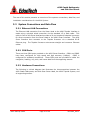
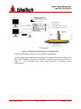
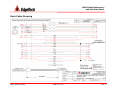
4 Little Brook Road West Wareham, MA 02576 Tel: (508) 291-0057 Fax: (508) 290-2491 4600 Swath Bathymetry and Side Scan Sonar Startup Guide Document No. 0012884 Email: [email protected] Website: http://www.edgetech.com REV E February 2013 4600 Swath Bathymetry and Side Scan Sonar The information, figures and specifications in this manual are proprietary and are issued in strict confidence on condition that they not be copied, reprinted or disclosed to a third party either wholly or in part without the prior written consent of EdgeTech. Any reproduction of EdgeTech supplied software or file sharing is strictly prohibited. © Copyright 2010 by EdgeTech. All rights reserved. Full SpectrumTM is a trademark of EdgeTech. Microsoft® and Windows® are registered trademarks of Microsoft Corporation. Kevlar® is a registered trademarks of the DuPont Company. Intel® and Pentium® are registered trademarks of Intel Corporation. Novagard G624® is a trademark of Novagard Solutions, Inc. 4600 Swath Bathymetry and Side Scan Sonar Warning—Read This First! All personnel involved with the installation, operation or maintenance of the equipment described in this manual should read and understand the warnings and recommendations provided below. Static Sensitive Devices This equipment contains devices that are extremely sensitive to static electrical charges. Therefore extreme care should be taken when handling them as static electricity may be present on the body and clothing. Normal handling precautions involve the use of anti-static protection materials and grounding straps for personnel. Radiation This equipment generates, uses, and can radiate radio frequency energy. Therefore if the equipment is not installed properly, it may cause interference with radio communications. The equipment has not been tested for compliance with the appropriate FCC rules designed to provide reasonable protection against such interference when operated in a commercial environment. Therefore when operating the equipment in a residential area, the user may be required to take whatever measures are needed and incur any expenses necessary to eliminate interference; it is the user's responsibility to verify that the system complies with the applicable FCC emission limits. High Voltages High voltages are present in the sonar head, the power amplifier and the topside processor. Always use caution when removing the electronics from these devices. Improper Line Voltage Operation with improper line voltage may cause serious damage to the equipment. Always ensure that the proper line voltage is used. 4600 Startup Guide i 0012884_REV E 4600 Swath Bathymetry and Side Scan Sonar Foreword This startup guide is intended to provide the user with an understanding of how to deploy and operate the 4600 System in order to complete a hydrographic survey using EdgeTech’s DISCOVER and an approved 3rd Party Acquisition and Post-Processing Software. The approved 3rd Party Topside specific to this startup guide is HYPACK®’s Hydrographic Surveying Software. EdgeTech assumes the end user has an assembled and tested 4600 System. It is also assumed that the user has a high level knowledge of the specific 3rd Party Topside Software, and if this is not the case, then training is required before proceeding. The contents encompassed within this STARTUP GUIDE provide a brief overview of the 4600 System and its basic operations. All other information (i.e. Warranty, Complete System Installation, Technical Details, Care and Maintenance, etc.) regarding the 4600 System is described within the 4600 Reference Manual. 4600 Startup Guide ii 0012884_REV E 4600 Swath Bathymetry and Side Scan Sonar Contents 1. Introduction ................................................................................................... 1 2. Product Specifications ...................................................................................... 5 3. Overview ....................................................................................................... 9 3.1 Data Formats .............................................................................................. 9 3.2 System Connections and Data Flow .............................................................. 10 3.2.1 Ethernet LAN Connections ........................................................................ 10 3.2.2 COM Ports .............................................................................................. 10 3.2.3 Hardware Connections ............................................................................. 10 3.2.4 Sonar Data Flow...................................................................................... 14 3.3 System Installation .................................................................................... 15 3.3.1 Over-the-Bow Deployment ....................................................................... 15 3.3.2 Over-the-Side Deployment ....................................................................... 16 4. Principles of Operations ................................................................................. 18 4.1 Sensor Installation ..................................................................................... 18 4.2 Confirming Supporting Data is Present .......................................................... 20 4.3 DISCOVER 4600 AND THE BATHYMETRIC PROCESSOR ................................................ 24 4.4 Operating HYPACK® ..................................................................................... 30 5. Contact and Service Information ..................................................................... 46 Deck Cable Drawing .............................................................................................. 1 4600 Acoustic Centers (Standard Body Type) ............................................................ 2 4600 Swath Bathymetry and Side Scan Sonar EdgeTech’s 4600 Startup Guide 1. Introduction The complete 4600 Bathymetry and Side Scan Sonar System consists of the 4600 Swath Bathymetry and Side Scan Sonar Head and the 4600 Topside Processing Unit (TPU). Figure 1: 4600 Topside Processing Unit (Left) and Sonar Head (Right) EdgeTech’s 4600 is a combined, fully integrated swath bathymetry and side scan sonar system that produces real-time high resolution 3D maps of the seafloor while providing coregistered simultaneous side scan and bathymetric data. The 4600 Sonar Head’s side scan sonar arrays are mounted on a streamlined body that is deployed over-the-bow of a survey vessel via a pole. Sonar data is transferred from the transceiver to the Topside Processing Unit on board via an Ethernet network interface. A detailed description of the 4600 Sonar Head configuration is presented in the REFERENCE MANUAL and its main components are illustrated in Figure 2. 4600 Startup Guide Page 1 of 46 0012884_REV E 4600 Swath Bathymetry and Side Scan Sonar Mounting Bracket Mounting Pole (Sold Separately) Tail Cone Sound Velocity Sensor (SVS) Sonar Processor Nose Cone Sonar Arrays (Port and Stbd) Figure 2: 4600 Sonar Head Components The 4600 Swath Bathymetry and Side Scan Sonar Head comes standard with a Sonar Processor, Port and Starboard Sonar Arrays, a Sound Velocity Sensor (SVS), a Nose and Tail Cone, and a Mounting Bracket. A Mounting Pole may be purchased separately to secure the 4600 System to a survey vessel. Note: Please become familiar with these terms in Figure 2, as they will be referenced throughout the rest of this startup guide. The 4600 Topside Processing Unit includes a 4600 Sonar Interface and a Processor (Figure 3). The 4600 Interface provides power to the Sonar Head and a link between the Sonar Head, any supporting sensors, and the Processor running EdgeTech’s DISCOVER 4600 Side Scan and Bathymetry Acquisition software and an approved post processing software. Note 1: At this point, the only hydrographic surveying and post processing software that has been approved by EdgeTech to interface with the 4600 software is HYPACK®. EdgeTech has worked exclusively with this company to provide a user friendly interface for the 4600 System. Note 2: The 4600 Topside Processing Unit comes standard with a third party software pre-installed unless the customer has specified otherwise upon time of purchase. Also, installing other software besides the ones supplied with the system can have undesirable 4600 Startup Guide Page 2 of 46 0012884_REV E 4600 Swath Bathymetry and Side Scan Sonar effects, such as poor and/or slow performance when acquiring bathymetry and side scan data, and the possibility of missing and/or incomplete data being acquired. 4600 Sonar Interface 4600 Topside Processor Figure 3: 4600 Topside Processing Unit The end user needs only to supply a source of data for position (latitude/longitude) and heading measurements, as well as roll, pitch, and heave data, to complete the acquisition package. Some examples that provide these types of data are presented in Figure 4. Figure 4: Optional GPS (Left)* and MRU (Right)** Sensors 4600 Startup Guide Page 3 of 46 0012884_REV E 4600 Swath Bathymetry and Side Scan Sonar * ** GPS provides position (latitude/longitude) and may or may not provide heading. MRU provides a source of roll, pitch, and heave measurements. 4600 Startup Guide Page 4 of 46 0012884_REV E 4600 Swath Bathymetry and Side Scan Sonar 2. Product Specifications 230 kHz Model Physicals Size Weight Construction Color Sealing : 1210 L x 260 W x 230 H (mm) 47.64 L x 10.13 W x 9.18 H (in) : 44 kg (98 lbs) : Aluminum and Polyurethane : Yellow and Black : Watertight Cover O-ring Seal with Purge Valve Side Scan Sonar Frequency : Range (per Side) : Range Resolution : Beam Width Along Track : Depression Angle : 230 kHz 225 m (738 ft) 30 mm (1.18 in) 0.64° (2-way) 30° 540 kHz Model 1210 L x 260 W x 230 H (mm) 47.64 L x 10.13 W x 9.18 H (in) 44 kg (98 lbs) Aluminum and Polyurethane Yellow and Black Watertight Cover O-ring Seal with Purge Valve 540 kHz 125 m (410 ft) 15 mm (0.6 in) 0.5° (2-way) 30° Interferometric Swath Bathymetry Maximum Swath : 350 m Range Resolution : 60 mm (2.36 in) Ping Repetition Rate : 25 m (82 ft) = 30 Hz, 50 m (164 ft) = 15 Hz, 100 m (328 ft) = 7.5 Hz Max Depth Below Tx : 120 m 150 m 30 mm (2.36 in) 25 m (82 ft) = 60 Hz, 50 m (164 ft) = 30 Hz, 100 m (328 ft) = 15 Hz 50 m Sonar Head Power Requirements DC Input : 48 VDC Power : 100 Watts 48 VDC 100 Watts 4600 Startup Guide Page 5 of 46 0012884_REV E 4600 Swath Bathymetry and Side Scan Sonar Environment Operating Temperature : 0°C to 40°C (32°F to 104°F) Storage Temperature : -20°C to 60°C (-4°F to 140°F) Relative Humidity : Operating 0 to 80%, Non-Operating 0 to 100% Topside Interface Interface Power Supply Topside Processor Operating System Interface Display Storage Power Supply 0°C to 40°C (32°F to 104°F) -20°C to 60°C (-4°F to 140°F) Operating 0 to 80%, Non-Operating 0 to 100% : 100 baseT Ethernet Serial RS-232 : 110/220 VAC Auto-Sensing 100 baseT Ethernet Serial RS-232 110/220 VAC Auto-Sensing : Windows 7 : 100 baseT Ethernet, Serial RS-232 : Dual 21” LCD Monitors, Expandable to 4 : 1TB min Hard Drive & RW-DVD : 110/220 VAC Auto-Sensing Windows 7 100 baseT Ethernet Serial RS-232 Dual 21” LCD Monitors, Expandable to 4 1TB min Hard Drive & RW-DVD 110/220 VAC Auto-Sensing Supplied Components 4600 Swath Bathymetry and Side Scan Sonar System with 20 m (65 ft) Deck Cable (Please refer to the Cable Drawing in the Appendix). Sound Velocity Sensor (SVS, located in the nose section of the Sonar Head) 4600 Topside Processing Unit – 4600 Interface and Topside Processor with DISCOVER 4600 Side Scan and Bathymetry Acquisition Software Hypack® Survey and Post-Processing Software System Restore Software (DVD) 2 x HP 21 in LCD Monitors HP Keyboard and Mouse 2 x Power Cables Spares Kit Manuals on CD 4600 Startup Guide Page 6 of 46 0012884_REV E 4600 Swath Bathymetry and Side Scan Sonar Optional Equipment 4600 Mounting Pole (see drawing in Figure 5 on Page 8) Crescent VS100 Series Hemisphere GPS (Figure 4, Page 3) SMC IMU Sensor (Figure 4, Page 3) HP 25 in LCD Monitor Samsung 25 in LCD Monitor 4600 Startup Guide Page 7 of 46 0012884_REV E 4600 Swath Bathymetry and Side Scan Sonar Optional Mounting Pole Example: Cable Path Protected by Fairing Max Cable Length = 20 m (65 ft) Ø 10 cm (4 in ) 1.02 m (3 ft) 10 cm (4 in) Bow of Survey Vessel 2.1 m (7 ft) Waterline 0.9 m (3 ft) Standard Tail Section Figure 5: Mounting Pole Concept Drawing 4600 Startup Guide Page 8 of 46 0012884_REV E 4600 Swath Bathymetry and Side Scan Sonar 3. Overview 3.1 Data Formats In order to collect valid survey data, the following is required to support the survey operations and correct processing of the 4600 Bathymetry and Side Scan echo data: a. GPS Position in NMEA format, latitude and longitude, b. Heading data in NMEA format or EM1000 binary format, c. Roll, Pitch and Heave data in TSS1 or EM1000 binary format, and d. Time sync data in NMEA format. This data may be supplied by 1, 2, or 3 individual sources. a. Position Data – this may be supplied via any of the following NMEA type sentences/messages: i. $xxGGK ** (Applanix PosMV Format) ii. $xxGGA iii. $xxGLL iv. $xxRMC v. $PTNL, GGK, … ** (Trimble Format) ** = Non-NMEA standard sentences b. Heading Data – this maybe input via: i. NMEA, $xxHDT sentence, or ii. EM1000 binary format along with attitude data c. Roll, Pitch, and Heave Data – this may be input via: i. EM1000 binary format, or ii. TSS1 format d. Time Input - supported sentences are in order of (priority/use) i. $xxZDA ii. $xxGGK (derived from data in item a. above) iii. $xxGGA iv. $xxRMC v. $xxGLL At minimum, items a., b., and c. above are required and must be supplied. 4600 Startup Guide Page 9 of 46 0012884_REV E 4600 Swath Bathymetry and Side Scan Sonar The rest of this section presents an overview of the systems connections, data flow, and installation considerations for the 4600 System. 3.2 System Connections and Data Flow 3.2.1 Ethernet LAN Connections The Ethernet LAN connection from the Sonar Head to the 4600 Topside Interface is made using a physical wired connection via the standard 15 m deck cable. This cable is fixed to the Sonar Head and provides a 20 pin Amphenol Industrial connector for direct connection from the Sonar Head to the 4600 Sonar Interface. The 4600 Sonar Interface then connects to the Topside Processor via a standard RJ-45 Ethernet plug. The Topside Processor auto-senses straight and crossover Ethernet cables. 3.2.2 COM Ports There are three COM ports provided on the 4600 Sonar Interface. COM1 and COM2 have been configured for high speed and high accuracy (10Mbps). COM3 is configured for standard connections. These COM ports are provided to intake the navigation, heading, roll, pitch, and heave data from the supporting sensors. 3.2.3 Hardware Connections The following is a block diagram that illustrates the interconnections between the 4600 Swath Bathymetry and Side Scan Sonar Head, the 4600 Topside System, and all supporting sensors. 4600 Startup Guide Page 10 of 46 0012884_REV E 4600 Swath Bathymetry and Side Scan Sonar 4600 TOPSIDE SYSTEM Monitor A Top: 4600 Sonar Interface Bottom: Topside Processor with DISCOVER and HYPACK Software COM1, COM2, COM3 Supporting Sensors Ethernet IP Address: 192.9.0.100 20m SONAR to TOPSIDE Deck Cable (48V/Ethernet/RS232 x 3/PPS/Trigger x 2) Monitor B Mounting Pole (Optional) Sonar Processor COM4 SVP Keyboard Track Ball 4600 Sonar Head IP Address: 192.9.0.101 Bathy/Side Scan Arrays (Port and Stbd) Figure 6: Hardware Data Flow Diagram for the 4600 System A larger representation of Figure 6 is provided in the Appendix. A more detailed block diagram demonstrating the interconnections and inputs to the 4600 Sonar Interface (Top section of the 4600 Topside Processing Unit) is shown in Figure 7. This illustration also gives three examples of possible sensor configurations. 4600 Startup Guide Page 11 of 46 0012884_REV E 4600 Swath Bathymetry and Side Scan Sonar Figure 7: Sonar Interface Connections Here, the 4600 Sonar Interface connects to the Sonar Head via the 20 pin Amphenol connector and Deck Cable. Navigation, heading, roll, pitch, and heave data from the supporting sensors via COM ports 1, 2, and/or 3, are inputted at the Sonar Interface, passed through the Deck Cable, and logged by the Sonar Processor in the Sonar Head. These data are then transmitted, along with the raw side scan data, with a common timestamp up the deck cable to the 4600 Sonar Interface, and passed to the Topside Processor via Ethernet Port 1 (IP Address: 192.9.0.100) via the Deck Cable. The Topside Processor then processes these data using the DISCOVER and BATHYMETRY software to send amplitude, angle and range data to the HYPACK® software for logging and post processing. This process is explained in further details in the following section. The HYPACK® and DISCOVER Side Scan/Bathymetry processors all run on the same computer. The first example depicts an Applanix PosMV system interfacing to the 4600 Sonar Interface. This type of system provides navigation (latitude/longitude), heading, roll, 4600 Startup Guide Page 12 of 46 0012884_REV E 4600 Swath Bathymetry and Side Scan Sonar pitch, and heave data and so no other sensor is required. connected to COM1 or COM2. The PosMV should be The second example shows the most common interfacing scenario, a GPS that provides navigation and heading data, accompanied by a motion sensor for attitude measurements. The COM ports should be assigned as such: COM1 = GPS (Navigation and Heading) COM2 = MRU (Roll, Pitch, Heave) These assignments may be interchanged between COM1 and COM2 because both ports have been configured for high speed and high accuracy. The third and last example portrays the situation where the supplied GPS does not provide heading data. In this case, three sensors are required – a GPS for navigation (latitude/longitude), a Gyro for heading, and a motion sensor for roll, pitch, and heave measurements. Therefore, all three COM ports should be used and assigned as follows: COM1 = Gyro (Heading) COM2 = MRU (Roll, Pitch, Heave) COM3 = GPS (latitude/longitude) The sensors allocated to COM1 and COM2 may be interchanged because of the same reason stated above in the second example. The GPS data, or latitude and longitude data, must be allotted to COM3 because it is not as important as the first two measurements. 4600 Startup Guide Page 13 of 46 0012884_REV E 4600 Swath Bathymetry and Side Scan Sonar 3.2.4 Sonar Data Flow To illustrate the data flow between DISCOVER, the BATHYMETRY PROCESSOR, and HYPACK®, the following block diagram is used. Heading, Position, and Motion Data 4600 Sonar Interface Raw Sonar Data Supporting Data DISCOVER Raw Sonar Data Information Gets Time Stamped and Sent Back to Interface Supporting Data 4600 Sonar Head Raw Sonar Data + Supporting Data Range/Angle Data + Supporting Information HYPACK® Side Scan Data Range/Angle Data HSX Files Bathymetry Processor Figure 8: Sonar Data Flow As demonstrated by the flow chart, the 4600 Sonar Interface acquires the heading, position (latitude/longitude), and motion (roll, pitch, and heave) data and relays this information to the 4600 Sonar Head via the Deck Cable. Here, the information is combined with the raw sonar data, time stamped with a common value, and sent back to the 4600 Sonar Interface. DISCOVER intakes the raw sonar data and sends it to the BATHYMETRY PROCESSOR, where the raw data is converted to range and angle data. The BATHYMETRY PROCESSOR transmits this range/angle data back to DISCOVER, where it is then displayed on the monitor, recorded as a *.JSF file, and packaged with the heading, position, motion, and side scan data. This complete data package is then sent to and used by HYPACK to generate three-dimensional bathymetry data files and to display side scan and bathymetry data on a monitor. Finally, these 4600 Startup Guide Page 14 of 46 0012884_REV E 4600 Swath Bathymetry and Side Scan Sonar three-dimensional bathymetry data files (.HSX) can be used post survey to generate hydrographic final products. 3.3 System Installation The 4600 System’s installation on the survey vessel is the customer’s responsibility, and certain considerations need to be kept in mind. The Sonar Head can be mounted on the side of a vessel, but it is recommended to secure the 4600 to the bow of the boat. Consideration must be given to keel clearance for both cases. This section outlines the 4600 Sonar Head deployment options. Note: If interested in purchasing the optional mounting pole for the 4600 installation, please contact Customer Service for a quotation using the information provided on page 46. 3.3.1 Over-the-Bow Deployment The first and recommended option is to mount the 4600 Sonar Head to the bow of the survey vessel. An example of an over-the-bow deployment is depicted in the photographs in Figure 9. A larger representation of these photographs is given in the Appendix. If help is needed with this type of installation, please do not hesitate to contact EdgeTech using the information provided in the Customer Service Section on page 46 of this manual. 4600 Startup Guide Page 15 of 46 0012884_REV E 4600 Swath Bathymetry and Side Scan Sonar Figure 9: 4600 Deployment, Option 1: Over-the-Bow 3.3.2 Over-the-Side Deployment An alternative to the latter is to mount the 4600 Sonar Head over the side of the survey vessel. An example of an over-the-side deployment is illustrated in the images in Figure 10. A larger representation of these photographs is given in the Appendix. If help is needed with this type of installation, please do not hesitate to contact EdgeTech using the information in the Customer Service Section on page 46 of this manual. 4600 Startup Guide Page 16 of 46 0012884_REV E 4600 Swath Bathymetry and Side Scan Sonar Figure 10: 4600 Deployment, Option 2: Over-the-Side 4600 Startup Guide Page 17 of 46 0012884_REV E 4600 Swath Bathymetry and Side Scan Sonar 4. Principles of Operations 4.1 Sensor Installation This section outlines the steps taken to install the 4600 Sonar Head and supporting sensors used to collect navigation, heading, roll, pitch, and heave data. 1. Mount the 4600 Swath Bathymetry and Side Scan Sonar System to the hull of the survey vessel. Please read the deployment configurations in Section 3.2 on page 15 and 16 for Sonar Head installation. 2. Position and secure a motion sensor to the vessel. Two positions for this are considered. a. Position 1: Mount the motion reference unit (MRU) at the vessel’s center of motion. This method requires a very stiff mounting of the Sonar Head to the boat. Any angular displacements between the sensor and the Sonar Head, induced as a result of roll/pitch motion and pole/mount bending, will be transferred to the final dataset. This method subjects the MRU to the least amount of lateral accelerations during vessel roll/pitch. Lever arm corrections for heave displacements must be applied. (Recommended) b. Position 2: An alternative method is to attach the MRU to the top of the Sonar Head’s mounting pole. In this case, the pole mount to the vessel needs to be stiff only in the yaw place, so that the vessel heading is still accurately coupled to the Sonar Head heading. This method is best if the pole/boat coupling is not ideal. Lever arm corrections for heave displacements are not required. However, long term roll angles changes (due to crew movement, etc.) are not corrected for. 3. Measure sensor. measure motion. HYPACK. the depth of the Sonar Head and its location relative to the MRU If the MRU was attached to the Sonar Head’s mounting pole, the relative location of the MRU sensor to the vessel’s center of Record these measurements as they will be used later as Offsets in 4. Setup the GPS as described in the GPS’ user manual. 5. Connect the Sonar Head to the 4600 Topside Interface via the 20 pin Amphenol Industrial connector. 4600 Startup Guide Page 18 of 46 0012884_REV E 4600 Swath Bathymetry and Side Scan Sonar 6. Connect the GPS to COM1 and the MRU to COM2 (assuming the GPS provides heading as well as position in latitude and longitude). Note: An alternative configuration might require a third sensor, such as a Gyro for heading data. In this case, the Serial port assignments should be Gyro = COM1, MRU = COM2, and GPS Position = COM3. Refer to Section 3.2.3 for more details. 7. Ensure the Ethernet from Port1 of the 4600 Topside Interface is plugged into the Ethernet Port1 of the Topside Processor (labeled SONAR). 8. Turn the Sonar Head ON by using the switch on the front side of the 4600 Topside Interface. 9. Wait several minutes. This waiting period allows the Sonar Head’s processing unit to connect with the Topside Processor. 4600 Startup Guide Page 19 of 46 0012884_REV E 4600 Swath Bathymetry and Side Scan Sonar 4.2 Confirming Supporting Data is Present To ensure the Sonar Head’s processing unit is communicating properly with the Topside Processor, follow these steps. 1. On the Desktop, launch Shortcut to sonar.exe. The following window should appear. Figure 11: Sonar 192.9.0.101 Remote Desktop Connection Window 2. Check the clock time of the sonar (bottom right hand corner of Figure 11) with the clock time from the GPS and the Topside Processor. Ensure all three have the same time stamp. 3. Click on Menu > Misc > Serial Port Information… 4600 Startup Guide Page 20 of 46 0012884_REV E 4600 Swath Bathymetry and Side Scan Sonar 4. Check each COM port in the drop down menu to ensure data is coming through for each device and in the correct format (Figure 12). a. COM1 = MRU a. COM2 = GPS b. COM4 = Sound Velocity Sensor in the nose of the Sonar Head Note: The GPS and MRU are interchangeable on COM1 and COM2 as long as the appropriate baud rate is set in the drop down menu next to the channel assignment in the Serial Port Information Window (Figure 12, red arrow). If all systems are working properly, close this window and proceed to Step 5. If there is an issue with one of the ports, please contact Customer Service using the provided information on page 46. 4600 Startup Guide Page 21 of 46 0012884_REV E 4600 Swath Bathymetry and Side Scan Sonar Figure 12: Serial Port Information Window 5. Now click on Menu > File > Show Status. appear as shown in Figure 13. 4600 Startup Guide Page 22 of 46 The System Status window will 0012884_REV E 4600 Swath Bathymetry and Side Scan Sonar Figure 13: System Status Window 6. On the right hand side of the window, click on the Config bullet under the Update button and then on the drop down menu named Config Item. 7. Select Serial and then click the Update button several times. 8. Check to make sure all sensors’ usage percentages are well below 80%. If they are not; increase the baud rates of the sensors until these percentages drop. 9. When satisfied with the incoming data, press OK in the System Status window, and then minimize the Sonar – 192.9.0.101 – Remote Desktop Connection window. 4600 Startup Guide Page 23 of 46 0012884_REV E 4600 Swath Bathymetry and Side Scan Sonar 4.3 DISCOVER 4600 AND THE BATHYMETRIC PROCESSOR EdgeTech’s DISCOVER display and control application allows recording of side scan and range/angle bathymetry data in the binary EdgeTech JSF file format. The JSF file format has been in use for 10+ years and has new public extensions to support the additional bathymetry data messages. This section states the basic functions of DISCOVER and the BATHYMETRIC PROCESSOR and how to operate them during a survey. A full description of DISCOVER is given in the 4600 REFERENCE MANUAL. If you are not familiar with previous versions of DISCOVER, please read Section 5.2 of the REFERENCE MANUAL before continuing. 1. Launch DISCOVER 4600 using the Desktop shortcut. appear as in Figure 14 and Figure 15. The two main windows will Figure 14: DISCOVER Main Window 4600 Startup Guide Page 24 of 46 0012884_REV E 4600 Swath Bathymetry and Side Scan Sonar Figure 15: BATHYMETRIC PROCESSOR Main Window 2. Ensure that the Sonar Head is connected to DISCOVER by ensuring the network is on (NET: ON) down in the right hand corner of the DISCOVER main window (Figure 14, circled in blue). 3. Check the clock time in DISCOVER and ensure it corresponds to the sonar, GPS, and Topside Processor’s clocks. This is done by looking at the time stamp listed next to the word Time: (Figure 14, arrow indicator in blue). 4. Navigate to the Towfish Control Tab and check the Sonar On box to turn ON the Sonar Head. Figure 16: Towfish Control Tab - Turning the Sonar On Note: If at any time, one or more of the systems (i.e. GPS, MRU, Sonar Head) have been disconnected or are not sending data to DISCOVER while the Sonar Head is turned on, a window (Figure 17) will appear displaying the unavailable system(s). If this window appears, check the connection to the unavailable system(s). If the problem persists, please call Customer Service using the information provided on page 46. 4600 Startup Guide Page 25 of 46 0012884_REV E 4600 Swath Bathymetry and Side Scan Sonar Sonar Head is ON and CONNECTED GPS/MRU is DISCONNECTED MRU/GPS is DISCONNECTED SVS is ON and CONNECTED Figure 17: Diagnostic Information Window 5. Ensure the correct supporting information is being inputted to the system on the appropriate COM ports by choosing View > Situation Status on the Bathymetric Processor main window (Figure 18 and Figure 19). Figure 18: Selecting the Appropriate Ports The choices available are OFF, ANY, COM1, COM2, etc. Ensure the correct strings (i.e. GGA, HDT, VTG, etc.) are set to ANY or set to their corresponding COM port. If only one source of each piece of information is provided to the system, the Situation Status window may look like the one presented in Figure 19. Also, the processed or not processed pitch/roll data is presented in this window as well. 4600 Startup Guide Page 26 of 46 0012884_REV E 4600 Swath Bathymetry and Side Scan Sonar Figure 19: Situation Status Window 6. To set up a recording directory, navigate to the Disk Tab and click Browse next to the Record File box. Usually the recording directory is located on the F:\Data Disk. Figure 20: Disk Tab in DISCOVER - Record 7. When ready, press the Record button on the right hand side of the Disk Tab. The name of the file will appear in the Record File: text box. To stop or pause a file, select the appropriate function button. Note: If a file is recorded in DISCOVER while data is being recorded in HYPACK, the file can be re-processed for bathymetric estimation using different parameters postsurvey. This recorded DISCOVER file provides useful for debugging and training purposes. 7. For basic playback, navigate to the Disk Tab (Figure 21) and select Browse next to the Playback File: box. Locate the desired JSF file and use the function buttons to play, stop, fast forward, etc. (boxed in green). 4600 Startup Guide Page 27 of 46 0012884_REV E 4600 Swath Bathymetry and Side Scan Sonar Figure 21: Disk Tab in DISCOVER - Playback 8. To adjust the basic bathymetric processing parameters in DISCOVER, select Bathymetry from the Top Menu and then Processing Parameters (Figure 22 and Figure 23). Figure 22: Discover 4600 Top Menu - Selecting Bathymetric Processing Parameters Here you can turn on/off the BATHYMETRIC PROCESSOR, adjust the echo strength (1/10%), SNR filter (dB), and Minimum Process Range (m). This window also allows you to specify if you would like to use/not use the external limits given by the 3rd Party Interface. The recommended parameters are shown in Figure 23 for a silty/sand type seafloor. 1 2 4 3 Figure 23: Basic Bathymetry Note 1: Ensure the Bathymetric Processing box is checked while recording a file, otherwise no bathymetry data will be processed or sent to Hypack. 4600 Startup Guide Page 28 of 46 0012884_REV E 4600 Swath Bathymetry and Side Scan Sonar For a full description of all the functions in DISCOVER and the BATHYMETRIC PROCESSOR please refer to Section 5.2 in the 4600 REFERENCE MANUAL. 4600 Startup Guide Page 29 of 46 0012884_REV E 4600 Swath Bathymetry and Side Scan Sonar 4.4 Operating HYPACK® The processed bathymetry and side scan data is sent in real-time to the HYPACK®/HYSWEEP® survey applications. These application display and record the bathymetric data in HYPACK’s HSX format. These HSX files can then be used off line in the MBMAX, SIDE SCAN MOSAIC, and other proprietary packages that support these formats, to edit, clean, and mosaic the collected data. This segment briefly explains how to use HYPACK® in order to complete a hydrographic survey. For more information on how to use HYPACK with the EdgeTech 4600 System, please refer to the EDGETECH 4600 HYPACK SOFTWARE GUIDE. Note: This section assumes the end user has a high level knowledge of HYPACK. If not, it is the sole responsibility of the customer to acquire training/support from HYPACK. 1. Place the white HYPACK Dongle in the front USB port of the 4600 Topside Processor in order to activate the HYPACK License. 2. Launch HYPACK and copy the EdgeTech4600 Project. This will copy all the necessary files in order to complete a survey with the 4600 system (Figure 24). Figure 24: Copy Project Window 4600 Startup Guide Page 30 of 46 0012884_REV E 4600 Swath Bathymetry and Side Scan Sonar 3. Give the copied project a relevant name, such as the area to be surveyed and the date (i.e. Port Everglades 10-28-2010). 4. Now, configure the Geodetic Parameters for the survey area. a. Select Preparation from the top menu in the HYPACK Shell (Figure 26, circled in red) and click on Geodesy. This same window may be reached by choosing the Geodesy shortcut from the shortcut menu (designated by red arrow in Figure 26). The following window should appear: Figure 25: Geodetic Parameters Window b. Configure the parameters according to the survey area. c. When finished, click OK. 5. Load any necessary background files needed to complete the survey. a. Under Project Files on the left side of the HYPACK main window (Shell, Figure 26), right click on the Background Files and select Add Files. b. Locate the background files needed and select Open. 4600 Startup Guide Page 31 of 46 0012884_REV E 4600 Swath Bathymetry and Side Scan Sonar Figure 26: Hypack Main Window (Shell) 6. Input any offsets for the 4600 Bathymetry and Side Scan Sonar System. (These values depend on how the system was mounted). a. Select Hysweep from the top menu of the HYPACK Shell (Figure 26, circled in red) and click on Hysweep Hardware. (Please refer to Figure 27 and Figure 28). b. Ensure the EdgeTech 4600 system is highlighted. c. Select the Offsets Tab at the top. d. Enter the offsets for Sonar Head 1, Sonar Head 2, and the MRU. In HYPACK, Sonar Head 1 and Sonar Head 2 represent the array on the port and starboard side of the underwater unit (Figure 2), respectively. Both sonar heads should have the same Forward and Vertical Offsets, while the Starboard offset should differ according to the acoustic centers. (Please refer to the Appendix for the Acoustic Center locations of each array). 4600 Startup Guide Page 32 of 46 0012884_REV E 4600 Swath Bathymetry and Side Scan Sonar e. When finished, click Close. Figure 27: Hysweep Hardware Window Figure 28: Hysweep Hardware Offsets 4600 Startup Guide Page 33 of 46 0012884_REV E 4600 Swath Bathymetry and Side Scan Sonar Note: These offsets are measured with respect to the vessel’s center of motion and should have been collected during sensor installation. 7. Select Survey on the top menu of the HYPACK Shell (Figure 26, circled in red) and choose Survey and Hysweep Survey. Five windows will appear as in Figure 29 and Figure 30: (1) Survey, (2) GPS NMEA-0183 with RTK Tide Option, (3) Edgetech 4600 Navigation, (4) Hysweep Survey, and (5) Hysweep Interface. Note: The GPS NMEA-0183 with RTK Tide Option and Edgetech 4600 Navigation windows will only appear if you have configured the mobile devices properly as described in Section III of the EDGETECH 4600 HYPACK SOFTWARE GUIDE. This is why it is important to copy the EdgeTech 4600 project as these devices are already configured for EdgeTech’s system. 8. Before continuing, ensure all systems and inputs are green in the Hysweep Survey window (Figure 30, top). Green indicates that each system and input is connected properly and all devices are on. If a device is highlighted in red, DISCOVER should have already displayed a warning message. Check the connection between the device and the Topside Processor. If problems persist, please contact Customer Service using the information provided on page 46. 4600 Startup Guide Page 34 of 46 0012884_REV E 4600 Swath Bathymetry and Side Scan Sonar Figure 29: Survey and Hysweep Survey Windows – Windows 1 through 3 4600 Startup Guide Page 35 of 46 0012884_REV E 4600 Swath Bathymetry and Side Scan Sonar Figure 30: Survey and Hysweep Survey Windows – Windows 4 and 5 9. On the Hysweep Survey window (Figure 30, top), choose View > Interferometry to bring up the interferometry window. Display Display Options Interferometry Options Range Settings Figure 31: Interferometry Window 10. Select the first button in Figure 31 to access the Ranges tab in the View Options window (Figure 32). This window allows the user to control the Minimum and Maximum Depth, Port and Starboard Offset Limits, Port and Starboard Angle Limits, and the Depth Range to Overlap Colors limit. 4600 Startup Guide Page 36 of 46 0012884_REV E 4600 Swath Bathymetry and Side Scan Sonar X Figure 32: View Options Window – Incorrect Way of Limiting Data Note 1: It is important to note here that it is not a good idea to limit your data by setting the Port and Starboard Angle Limits under the Ranges tab (Figure 32). When the Port and Starboard Angle Limits are set too low (> 90°), the data becomes biased, resulting in a false curvature of the seafloor. Figure 33 and Figure 34 illustrate this “biasing” concept. Note 2: The Port and Starboard Angle Limits in this example have been set to 55˚, the field of view of a traditional multibeam! 4600 Startup Guide Page 37 of 46 0012884_REV E 4600 Swath Bathymetry and Side Scan Sonar Figure 33: Interferometry Window Illustrating a Biased Data Set Caused by too low of a Port and Starboard Angle Limit Figure 34: Profile Window Illustrating a Biased Data Set Caused by too low of a Port and Starboard Angle Limit 4600 Startup Guide Page 38 of 46 0012884_REV E 4600 Swath Bathymetry and Side Scan Sonar Since the 4600 System has a 200˚ field of view, the correct way to limit the bathymetry data is setting the Port Angle Limit and the Starboard Angle Limit set to 100˚ (Figure 35). Figure 35: View Options Window – Correct Way of Limiting Data 4600 Startup Guide Page 39 of 46 0012884_REV E 4600 Swath Bathymetry and Side Scan Sonar If the data needs to be limited, adjust the Port and Starboard Offset Limits instead. This will only keep the data points included within the horizontal range specified by these offset limits without biasing the data points. A proper way to threshold the data is demonstrated in Figure 36 and Figure 37. Figure 36: Correct Window Thresholding (Interferometry Window) Figure 37: Correct Window Thresholding (Profile Window) 11. Select the third button in Figure 31 to access the Interferometry Options. This window may also be accessed by right clicking on the Interferometry window and selecting Options. 4600 Startup Guide Page 40 of 46 0012884_REV E 4600 Swath Bathymetry and Side Scan Sonar 12. Check the Filter along track box under Filtering (boxed in red in Figure 38). Set the number of bins to 50 and set the Height/Weight between (2-5)/(0.3-0.6). The parameters shown below work well for rejecting bad data when the seafloor is behind an object. Figure 38: Interferometry Options 13. Under Beamforming (boxed in green, Figure 38), the number of beams or number of points per swath should typically be less than or equal to 400. 14. Ensure that the Mode drop down menu is set to Bin by Horizontal Offset. 15. The Bin Size should be set to a value that will get the desired Max Width (or max swath coverage). Here the number of beams was set to 240 and the bin size was set to 0.5 m to acquire the desired swath coverage of 120m. Note: For higher resolution, the recommended settings are 400 Beams, by 0.25m Bin Size to achieve a total swath of 100m. If a smaller/larger swath is desired the 4600 Startup Guide Page 41 of 46 0012884_REV E 4600 Swath Bathymetry and Side Scan Sonar Bin Size can be adjusted accordingly, or the Port and Starboard Offset Limits can be fine-tuned. 16. On the Hysweep Survey Window (Figure 30, top) choose View > Profile Window to bring up the two-dimensional profile of the seafloor (Figure 39). Display Range Figure 39: Profile Window using Sounding Points Viewing Option 17. Click on the second button in Figure 39 to bring up the Display Options. This window may also be accessed by right clicking on the Profile Window and selecting Options, or by hitting the F9 key. 18. This window allows the user to pick and choose different viewing methods of the data. Choose each one and hit Apply to see what the data looks like. (The preferred viewing is shown in Figure 40). When finished, click OK. 4600 Startup Guide Page 42 of 46 0012884_REV E 4600 Swath Bathymetry and Side Scan Sonar Figure 40: View Options Interface, Display Tab 4600 Startup Guide Page 43 of 46 0012884_REV E 4600 Swath Bathymetry and Side Scan Sonar 19. On the Hysweep Survey Window choose View > Multi-Beam Waterfall to bring up the waterfall view of the seafloor. Display Sounding Colors Range Figure 41: Multibeam Waterfall using Color Tin Viewing Option Note 1: Range Settings and Display Options buttons for all three windows, portray the same settings from the same window. The Sounding Colors button allows the user to change the color scheme of the Multibeam Waterfall window. Note 2: There are other windows that Hysweep Survey provides and these are accessed the same way as in step 16. 20. When ready to collect data, select the Start Logging feature from the Survey window by Logging > Start Logging… or by selecting the shortcut key . Figure 42: Survey Window (First Display Window in Figure 30). 4600 Startup Guide Page 44 of 46 0012884_REV E 4600 Swath Bathymetry and Side Scan Sonar Note: DISCOVER could be recording simultaneously as HYPACK is logging data. If desired, navigate to DISCOVER and click the Record button from the Disk tab. 19. When finished with collecting data, select the Stop Logging feature from the Survey window by Logging > Stop Logging… or by selecting the shortcut key . Note: If DISCOVER was recording, please make sure to stop this recording too. For more details on logging survey data please refer to Section IV of the EDGETECH 4600 HYPACK SOFTWARE GUIDE. 20. Repeat Steps 20 and 21 for as many data files as needed to complete the survey. 21. When completed with the survey, save and exit out of all applications and turn off the 4600 system using the power switch on the Topside Interface. 22. Shut down the Topside Processor by exiting out of all programs, then Start > Shut Down. 4600 Startup Guide Page 45 of 46 0012884_REV E 4600 Swath Bathymetry and Side Scan Sonar 5. Contact and Service Information For product service or support, please contact: EdgeTech 4 Little Brook Road West Wareham, MA 02576 Tel: (508) 291-0057 Fax: (508) 291-2491 Email: [email protected] Note: If it is necessary to return the equipment for service, a Returned Material Authorization (RMA) number is required prior to returning any equipment to EdgeTech. This is to assist EdgeTech in recognizing the returned equipment when it arrives at EdgeTech’s receiving dock, and to assist customer service representatives in tracking the returned equipment while it is at EdgeTech’s facilities. Please refer to the 4600 REFERENCE MANUAL for the correct RMA Procedure. 4600 Startup Guide Page 46 of 46 0012884_REV E 4600 Swath Bathymetry and Side Scan Sonar APPENDIX A 4600 Startup Guide Page A of 46 0012884_REV E 4600 Swath Bathymetry and Side Scan Sonar Deck Cable Drawing 20 Meters 4600 Startup Guide Page A1 of A2 REV E 4600 Swath Bathymetry and Side Scan Sonar 4600 Acoustic Centers (Standard Body Type) 4600 Startup Guide Page A2 of A2 REV E