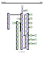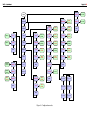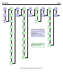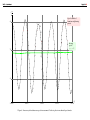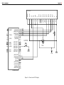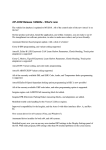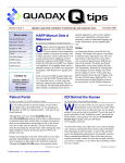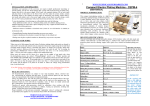
1
YACC — User Manual
Yet Another Car Computer
Yet Another Car Computer is do-ityourself electronic device addressed to
middle skilled hobbyists.
Opel cars are primary destination
of YACC which works with cars displays, preserves genuine interior look
and seems to be a factory device.
Moreover, YACC can work with popular alphanumeric LCD displays. This
feature, extended configuration and
painless calibration method make possible to install YACC in practically every
car equipped with fuel injection.
Functions
1) Instantaneous speed measurement with precision of 0.1 km/h.
Page 1 of 17
7) Used fuel gauge. Low fuel level
warning: (a) estimation of fuel
level in the tank, (b) distance estimation remaining on the tank
given mileage.
8) Three trips.
Each trip meters
distance, average speed, time of
journey, average and total fuel
consumption and cost of fuel for
longer periods of time.
9) Tachometer.
10) Battery voltage meter.
11) Manual steering of automatic antenna. It is possible not to use
the antenna e.g. when listening to
CD.
nized. Pressing and holding the button for less than 1 second is called
9.5 < TANK CAP − F ≤ 10.5
a short press. Pressing and holding
the button for more than 1 second is
called a long press. Short presses cycle
b) Estimated distance remaining on
the display between successive working
the tank (in kilometers).
modes. Long presses are used to enter
D124 51.4
commands (e.g. to reset fuel counter,
This distance is calculated using
to begin a trip etc.)
current average fuel consumption
A [ ] symbol is shown when a long
FA.
press is available.
Working modes are shown on figures
When the vehicle stops (condition
5, 6 and 7. Short presses are reprev < 0.5 km/h) the following values are
sented by thin, vertical lines
displayed.
SPD
M/A/T
M 12005
12) Sport mode. 1/4 mile and 0. . .60,
0. . .80, 0. . .100 km/h runs.
2) Traveled distance measurement.
Informations from points 2, 3, 4 and
Automatically shown every time 5 are automatically displayed when vevehicle stops.
hicle stops. While going through the
city they give an interesting possibil3) Average speed measurement. Two
ity of observations of mileage, comparvalues are measured: (a) total avison the average speed with the speed
erage speed, (b) average speed corof e.g. bicycle, realizing how much time
responding to motion i.e. only rewe spent in traffic jams and how big car
ferring to periods of time when veexpenses are.
hicle is moving.
Instantaneous speed gives a chance
to
estimate
how big an excess of factory
4) Time of journey and time when vespeedometer
indication is.
hicle is stopped measurement.
Average fuel consumption corresponding to segment of the road fo5) Cost of used fuel.
cuses our attention on big differences
6) Fuel consumption: (a) average depending on traffic conditions and
since key was turned on, (b) in- driving style.
stantaneous corresponding to last
5 second, (c) instantaneous cor- Using the YACC
responding to road segment of
length ranging from 50 to 1000 Single button is used to control the demeters.
vice. Two types of presses are recog-
a) Traveled distance in meters
or for distances greater than 100
km in kilometers.
RPM
and long presses by thick, horizontal
ones.
TRIPS
TRIP 1
Basic mode
While driving instantaneous speed v is
shown in km/h.
SPD 50.2
If tank capacity (FUEL → TANK CAP) is
set and an amount of fuel remaining in
tank (difference between defined tank
capacity and used fuel F) is lower than
warning level (FUEL → WARN LEV), than
the following data are shown instead of
letters SPD.
a) Tank fuel level (in liters).
F10 50.2
Here F10 means that
KM 1200.1
b) Average speed, excluding the
time when the vehicle was
stopped/total average speed in
km/h.
A 40/32.7
c) Total time of trip/time when vehicle was stopped in minutes.
T 20/4
For total trip time greater than 60
minutes, both times are displayed
one after another. Time of trip
T 2H30
and time
stopped.
W 0H25
d) Fuel cost.
EUR 20/4.5
when
vehicle
was
YACC — User Manual
The first value corresponds to TRIP
1 and is shown only for active trip.
The second value corresponds to
current traveled distance (since
key was turned on).
Distance, travel time and fuel cost measurements start each time when the
key is turned on (precisely since the
first moment when v ≥ 0.5 km/h) and
end when the key is turned off.
Tachometer
The value of engine revolutions per
minute is shown.
RPM 1200
Average fuel consumption
Average fuel consumption corresponding to traveled distance (since the key
was turned on) is shown. The unit is
l/100 km.
FA 7.5
User can choose between displaying
numerical values related to consumed
fuel (averages FA, FH, FK, FX, fuel counter
F) with accuracy of one or two decimal
digits after decimal dot (FUEL → ACC).
One should remember however, that
TID allows to display decimal point between two most right digits only. With
two digit accuracy result will be shown
as integer with unit 0.01 l/100 km.
FA 750
Instantaneous fuel consumption per
hour
Instantaneous fuel consumption corresponding to last 5 seconds is shown.
The unit is l/h.
FH 1.2
Page 2 of 17
Instantaneous fuel consumption corresponding to segment of the road
Instantaneous fuel consumption corresponding to the preceding segment of
the road of selected length (10 m, 20 m,
50 m, 100 m, 200 m, 500 m, 1 km) is
shown. The unit is l/100 km.
FK05 8.5
or
FX05 8.5
Long press enters settings mode enabling to select length of the segment of
the road. Next short presses cycles between values 10 m (FK01), 20 m (FK02),
50 m (FK05), 100 m (FK1), 200 m (FK2),
500 m (FK5), 1 km (F1K). Long press
switches between FK and FX modes. In
FK mode all amount of used fuel is included in calculations. In FX mode fuel
used when vehicle was stopped is not
included. YACC returns to main menu
automatically after 5 second.
switches to editor mode (EDIT) Trips
where you enter the amount (in
Trips allows to measure total distance,
0.01 l) of fuel added.
time and used fuel for longer periods.
c) CAL – choose this command when Long press in
TRIPS
you are filling your tank and want
mode
switches to trips related menu
to use the data collected during
where
short
presses cycle through sucthe past tank to calibrate your
cessive
trips
(TRIP 1, TRIP 2, TRIP 3)
fuel coefficient cf uel . Long press
and
command
EXIT returning to main
switches to editor mode (EDIT)
menu
—
automatically
after 5 seconds
where you enter the amount (in
or
with
a
long
press.
0.01 l) of fuel added during this
For each trips following values are
fill-up.
displayed every 2 seconds
d) PRICE – fuel price. Long press
switches to editor mode (EDIT)
where you enter fuel price in 0.01
currency unit. Currency symbol can be defined in FUEL →
CURRENCY mode.
e) EXIT – returns to previous menu.
Automatically after 5 seconds or
with a long press.
a) trip number, e.g.
TRIP 1 *
b) traveled distance,
c) average speed,
d) time of trip,
e) average fuel consumption,
Fuel gauge
f) total fuel consumption,
The amount of fuel used so far is Fuel cost
shown. The unit is l.
F 31.2
Fuel cost corresponding to traveled disLong press enters the fuel related tance is shown.
menu. Successive short presses cycle
EUR 10.6
through following commands.
g) fuel cost.
a) RESET – counter reset. Use this
command every time you fill up
but don’t want to recalibrate fuel
coefficient cf uel . Long press resets
the counter and confirms with
message
DONE
b) ADD – use this command every
time you are filling your tank but
not completely full. Long press
Battery
The battery voltage is shown. The unit
is V.
BATT 12.2
YACC switches to this mode immediately after key is turned on giving possibility to observe voltage drops when
vehicle ignition is attempted. After 20
seconds YACC returns automatically to
basic mode.
Symbol * after number means that trip
is active i.e. distance, time and fuel
data are updated all the time. Lack of
* means that trip was ended.
Long press begins or ends the trip.
If the trip is inactive the command
BEGIN n
is shown where n corresponds to trip
number. Next long press resets all trip
related data and marks trip as active.
The action is confirmed with
DONE
Since that moment distance, time and
fuel data will be updated all the time.
If the trip is active the command
END n
YACC — User Manual
Page 3 of 17
is shown. Next long press ends the trip.
The action is confirmed with
DONE
YACC switches to BATT mode for 20 seconds immediately after key was turned
on. During that time period a single
long press resets and begins TRIP 1.
During radio use a long press (if Defaults
not connected with another command)
changes antenna position to the oppo- Astra F
site one.
PRESETS → ASTRA F. Long press recalls
default fuel measurement values for Astra F.
Turning the key off
Sport mode
YACC turns off after 30 seconds of idleness.
Long press in basic mode switches
to sport mode. Short presses cycle
through runs: 1/4 mile, 0. . .60, 0. . .80,
0. . .100 km/h.
YACC automatically prepares to new
run each time vehicle is stopped. Run
name (1/4, 60, 80, 100) is shown on the
left side and word ready RDY on the right
one.
1/4 RDY
Timing commences automatically upon
detection any motion. The percent relative value of distance (speed) is shown
on the left side. Run time in second is
shown on the right side.
47% 10.2
At the end of the run timing stops and
run name is shown once more on the
left side.
1/4 21.0
Long press in sport mode switches back
to basic mode.
FUEL → COEF
FUEL → SOURCE
3 669 000
L
Astra G
Configuration
PRESETS → ASTRA G. Long press recalls
Pressing and holding button for 5 sec- default fuel measurement values for Asonds in tachometer mode switches to tra G.
configuration menu. A ”stereo” symbol
FUEL → COEF
27 700
appears on 8–digit display and ”Dolby”
FUEL
→
SOURCE
F
symbol on 10–digit one. 20 seconds
idleness switches automatically back to
basic mode.
Speed and distance
Calibration
Editor
Editor allows to enter numerical values and is available in selected working
modes. Editor is always entered with
a long press. Next short presses cycle through successive digits and commands CANCEL and SET. The SET command is visible only when a value has
been changed and a new value is in
proper range. Long press during SET
command stores a value, ends editor
Manual antenna steering
mode and returns to the mode editor
When you turn radio on an antenna was started from.
Long press during CANCEL command
status
ends editor mode without any changes.
ANT ON
or
Long press during digit selection
ANT OFF
switches into a mode which allows to
is shown for 5 second. Short press change digit value. Short presses sechanges the state of the antenna to the lect new value and a long press accepts
opposite one.
it.
SPEED → DISTANCE. Use the following
procedure.
Begin TRIP 1 and reset
the mechanical distance counter at the
same time. Travel some tens of kilometers. With a long press switch to editor mode and enter traveled distance in
meters. The calibration coefficient cdist
will be calculated automatically.
One needs to remember that most
mechanical counters work in two directions — count downward while going backward. YACC uses a pulser and
does not distinguish directions.
Instantanous speed averaging
SPEED → NOISE. YACC uses a simple algorithm to achieve better precision of
speed measurement. The measurement process lasts approximately SPEED
→ T MIN. Number of recorded impulses
correspoding to traveled distance is divided by measurement time.
Traveled distance impulses are generated by special devices called pulsers.
Construction of pulsers varies. Very often they are based on rotating wheel.
Mechanical inaccuracies of workmanship, looseness, axis and propel cable
vibrations can cause additional errors.
Figure 8 shows calculations of instantaneous speed based on recorded times
of two successive impulses.
Result analysis indicates that for
this specific case pulser generates 15
impulses with every revolution. Therefore it would be better to use time periods corresponding to multiply of 15
impulses.
In editor mode enter the value SPEED
→ NOISE in range 0. . .99. Value 0 turns
averaging off. If during single measurement less than 2·SPEED → NOISE
impulses are recorded (small speeds)
than instantaneous speed is calculated
without averaging. For other cases the
biggest multiply of SPEED → NOISE impulses is used in calculations.
Calibration coefficient
Signal selection
SPEED → COEF. In editor mode enter
cdist value in range 1. . .65 535 equal to
number of impulses corresponding to 1
km.
SPEED → SOURCE. The letter R corresponds to rising edge and the letter F
to falling one. Long press changes between R and F.
YACC — User Manual
Minimum measurement time
Page 4 of 17
will be shown as integer with unit 0.01
l/100 km.
SPEED → T MIN. In editor mode enter
value in range 10. . .110 in hundred
Calibration coefficient
parts of second.
FUEL → COEF. In editor mode enter cf uel
value in range 1. . .99 999 999 equal
to the sum of impulses lengths correSPEED → T MAX. In editor mode enter
sponding to 1 liter of fuel.
value in range 10. . .110 in hundred
parts of second.
Reading fuel consumption data
7A
7B
7C
8A
8B
8C
Tachometer
04358
01599
57383
04346
01594
08461
Calibration coefficient
RPM → COEF.
Long
presses
cycle
through subsequent crpm coefficient
values: 1, 2, 3, 4, 5, 6, 12 , 31 , 14 , 51 , 16 .
Maximum measurement time
Fuel
Tank capacity
FUEL → TANK CAP. In editor mode enter
tank capacity (value in range 0. . .250)
in liters. Value 0 turns low fuel level
warning off.
Warning level
FUEL → WARN LEV. In editor mode enter
value in liters in range 0. . .99. Value 0
turns low fuel level warning off.
Currency symbol
FUEL → CURRENCY. In editor mode enter
three letter currency symbol (e.g. EUR,
USD etc.)
Accuracy
FUEL → ACC. Long press switches between displaying numerical values related to consumed fuel (averages FA, FH,
FK, FX, fuel counter F) with accuracy
of one or two decimal digits after decimal dot. One should remember however, that TID allows to display decimal point between two most right digits only. With two digit accuracy result
FUEL → HISTORY. In this mode one
can read data necessary to compute
fuel consumption calibration coefficient cf uel . Short presses cycle between
successive results. 20 seconds of idleness returns to basic mode.
Results are shown in order reverse
to chronological (1 — past fill, 2 — fill
before past etc.) A single fill is represented by 3 values: A — amount of fuel
in 0.01 liters, B — beginning 5 digits
Σf , C — ending 5 digits of Σf .
Example results.
1A 04328
1B 01855
1C 82273
2A 04409
2B 01619
2C 59814
3A 03844
3B 01313
3C 73735
4A 04163
4B 01538
4C 56441
5A 04312
5B 01553
5C 67922
6A 03736
6B 01389
6C 54037
Liters
1.
2.
3.
4.
5.
6.
7.
8.
43.28
44.09
38.44
41.63
43.12
37.36
43.58
43.46
Σf
185
161
131
153
155
138
159
159
582
959
373
856
367
954
957
408
273
814
735
441
922
037
383
461
Edge selection
RPM → SOURCE. The letter R corresponds
to rising edge and the letter F — falling
one. Long press changes between R and
F.
Minimum measurement time
We assume that amount of used fuel RPM → T MIN. In editor mode enter
vf uel is proportional to total length Σf of value in range 10. . .110 in hundred
parts of second.
recorded impulses
vf uel · cf uel = Σf
The method used to obtain value of
cf uel consists in filling up the fuel tank
of car (until the pomp stops). However
this method has potentially many errors like inaccuracy of the pomp work,
the moment pomp stops, etc.
Results are shown on figure 9.
Points corresponding to fills 2, 4, 5,
6, 7 and 8 are approximately linear.
Fills 1 and 3 have thick errors and has
been excluded from further analisys. A
straight line y = cf uel · x has been fitted
with least square method.
Maximum measurement time
RPM → T MAX. In editor mode enter
value in range 10. . .110 in hundred
parts of second.
Battery
Calibration
BATTERY → VOLTAGE. Measure a battery
voltage with a multimeter. With a long
press switch to editor mode and enter
measured value in units 0.01 V. The
calibration coefficient cbatt will be calculated automatically.
Signal selection
FUEL → SOURCE. The letter L selects
length measure of low level, the letter
H — high one, the letter R counts rising
edges and F — falling ones.. Long press
cycles through L, H, R, F.
Calibration coefficient
BATTERY → COEF. In editor mode enter
cbatt value in range 1. . .65 535. The A/D
converter resolution is equal to 10 bits.
Value u =1 023 corresponds to voltage
YACC — User Manual
Page 5 of 17
For a single line the way of work cor1.1 V. The value shown in battery voltage mode BATT is calculated with the fol- responds to TID display.
lowing formula.
For two lines, the upper one displays
instantaneous speed and estimation of
cbatt · u
fuel and distance remaining on your
10 000
tank. The lower line corresponds to TID
display.
Radio
Manual antenna steering
RADIO → ANT. Value YES enables and
value NO disables manual antenna control. Long press changes value to opposit one.
When manual steering is disabled
antenna opens automatically with radio turning on and closes 10 second after turning radio off.
Assembly in the car
Supply
Supply circuit uses low drop voltage
regulator IC5. Key on voltage pulls
PWR2 line low which in turn switches
T1 transistor on and powers the microcontroller. Microcontroller keeps PWR4
line low during work and keeps power
even after turning key off. Concurrently YACC monitors key on voltage by
reading state of PWR1 line.
Elements assembly on the circuit board
is the first step. The microcontroller
IC1 is mounted into a socket.
YACC was designed for control button which switches the ground. This
corresponds with 8–digit displays (e.g.
Astra F).
Second line offset
In 10–digit displays (e.g. Astra-G)
the
dot button switches positive voltLCD → OFFSET. In the editor enter an
age.
In order to adjust YACC to work
address (number in range 0. . .127) of
A/D converter
with
10–ditig
displays you should omit
the first character in the second line.
assembling
D3
diode and make two
This option allows to deploy practically A/D converter input voltage range is
additional
connections
on the circuit
every model of LCD display.
0. . .1.1 V. Battery voltage measurement
board.
uses a divider with R4 and R5 resistors.
A comprehensive description of asDiodes D1 and D2 protect A/D input.
sembly is available on the web page
TID display selection
Connection with factory radio re- The YACC computer works with factory
display used in Opel cars. There are
ceiver
two variants of displays with 8 or 10
RADIO → OPEL. Value YES allows to use digits. The proper display type can be
factory radio receiver. When receiver is selected with 8/10 jumper.
in use YACC does not send any data to
TID. Value NO corresponds to constant
8/10 jumper
access of YACC to TID display. If one
open 8 digit display
use factory radio with this setting data
close 10 digit display
collision will occur and none or random
data will be displayed. However this
will not lead to any disfunction.
Construction
Schematic diagrams are shown on figLCD display
ures 10 and ??. The microcontroller
IC1
running with clock 12 MHz and
Display width
supplied with 3.3 V is the main eleLCD → WIDTH. Select number of charac- ment. At such supply voltage the miters in a single line in range 12. . .20.
crocontroller is slightly overclocked but
works correctly.
Low supply voltage guarantees
Number of lines
proper work of device when ignition
LCD → LINES. Select number of lines is attempted what usually cause big
(one or two).
battery voltage drops.
Outputs
e-pmk.eu/en/diy/yacc/know-how
IC2 and T2 are used to convert 3.3 V
level signals into 12 V level ones.
If you don’t intent to manually control automatic antenna than skip
assembly of T2, R13 and R16 elements.
YACC and LCD displays
Due to users feedback the possibility
of communication with popular LCD
displays based on HD44780 driver has
been added to the YACC computer.
Inputs
IC3 is used to convert 12 V level signals into 3.3 V level ones. Additionally
for traveled distance signal (ICP), engine
revolution signal (INT1) and fuel consumption signal (INT0) Schmidt triggers
(built with IC4) can be used.
Triggers are activated by jumpers
according to the following table.
Schmidt trigger
bypassed
used
Connection
The way of connection of LCD display to YACC computer is shown on
figure 10.
Connections have to be
made with wires soldered directly to the
points on printed circuit boards.
Depending on the display type it
could be necessary to use contrast regulation (R1 variable resistor) and/or
backlight current restraint (R2 resistor).
YACC — User Manual
Page 6 of 17
Supply
(real value for test car), the counter
Measurement time is determined by
range is over 250 000 km.
two values: the minimum time SPEED
Depending on current consumption by
Additionally, times of the rising (R)
→ T MIN and maximum time SPEED →
LCD display (backlight current ranging
T MAX. One can apply own values to
from tens to hundreds mA is the most
u
these coefficients to achieve the best
significant factor) it would be necessary
fit to own car. The measurement int
t
n+k
n
to use additional voltage regulator or
cludes the lowest number k impulses
might be possible to use existing one
(not greater than 255), such that tn+k −
(after substituting original IC5 LP2950tn >SPEED → T MIN. For big speeds the
3V3 circuit with +5V equivalent, e.g.
measurement could last shorter than
LP2950-5V0 or 78L05).
SPEED → T MIN. When at least two impulses will not be recorded during SPEED
t
→ T MAX time instantaneous speed is
Display selection
assumed to 0 and a new measurement
Display selection is determined with or falling (F)
starts immediately.
PC3 input. Connecting the input with
When the value of coefficient SPEED
u
the ground (with LCD/TID switch or
→ NOISE> 0 and the number of
simply with wire) selects LCD display.
recorded impulses k > 2·SPEED → NOISE
tn+k
tn
Leaving the input unconnected selects
only k̃ beginning impulses are considTID display.
ered in the calculation, where k̃ ≤ k is
the biggest multiple of SPEED → NOISE.
Fuel mileage
Fuel consumption is calculated from
the length or count of impulses generated by Engine Control Module (ECM)
or taken from signal driving injector.
(a) Times of rising and falling edges
are recorded with the same accuracy as
in instantaneous speed measurement.
Maximum length of impulse equals approximately 21 ms. Longer impulses
are rejected.
Times of impulses t2 − t1 and t4 − t3
corresponding to high (H)
u
t1 t2
t3
t4
Restoring factory settings
Improper configuration can couse that
t
information will not be displayed properly.
Closing 8/10 jumper and powering edges are recored. Edge type can be
selected during configuration (SPEED →
device restores factory settings:
SOURCE mode). Resolution of measurements is equal approximately to 21 µs.
LCD → WIDTH
12
According to the number of imLCD → LINES
1
pulses
k and their times tn , tn+k instanLCD → OFFSET 64
taneous speed is calculated with the
following formula
Measurement methods
Speed and distance
Speed and distance measurements use
electric impulses generated by a special
device called pulser.
Impulses are counted in 32–bit
counter. Thus, assuming that 1 km
corresponds to cdist = 16 900 impulses
Engine revolution speed
Measurement of engine revolution
speed is analogous to measurement of
instantaneous speed. The RPM value
is calculated with the following formula or low (L) level respectively
crpm · k ·
46 875 · 60
tn+k − tn
t
h rev i
min
u
t1 t2
t3
t4
Selection of the value crpm from set
1, 2, 3, 4, 5, 6, 21 , 13 , 14 , 15 , 16 (RPM → COEF
mode) allows to fit to own car.
46 875 · 3 600 h km i
k
·
Minimum and maximum times of
cdist
tn+k − tn
h
measurement are determined by RPM →
Setting value of cdist coefficient in T MIN and RPM → T MAX configuration
t
range 1. . .65 535 makes it possible to settings.
adjust device to every car. Suggested
Measurement includes no more
calibration method is explained in fur- than k = 255 impulses and can last
ther parts (SPEED → DISTANCE i SPEED shorter than RPM → T MIN for big rev- are summarized in 32-bit counter Σf .
→ COEF modes).
olution speeds.
(b) Rising
YACC — User Manual
Page 7 of 17
u
1
clock counters with resolution equal
approximately to 1.40 second. Therefore the maximum range is over 190
years.
2
Accuracy of mathematical calculations
t
or falling
u
1
2
Mathematical calculations are performed with 64–bit precision. When a
calculated value is big so much that
cannot fit on a display an overflow condition OVF is shown.
Technical specifications
t
edges are counted in Σf .
Selection of corresponding signal
level or edge is set during configuration
(FUEL → SOURCE mode). The amount of
used fuel is calculated with the following formula
Σf
cf uel
[l]
Supply voltage: 5. . .27 V
Supply current: 21 mA
YACC has a very large reserve of
computational power. Recorded, maximum traveled distance signal (ICP) frequency is equal to about 50 kHz, and
engine revolution signal (INT1) to about
115 kHz.
In the test car (cdist = 16 900,
crpm = 1/2) traveled distance signal
at assumed speed 180 km/h corresponds to frequency 845 Hz and uses
1.7% available computational power.
Engine revolution signal at assumed
speed 6 500 rpm corresponds to frequency 216 Hz and uses 0.2 % computational power.
Calibration process consists in estimation of cf uel coefficient, which value
is in the range 1. . .99 999 999 (FUEL
→ COEF mode). In the test car cf uel
value turned out to be 3 669 000 and
corresponded to fuel counter capacity Factory settings
over 1 170 liters. Calibration process
Factory settings correspond to Astra F
is described in detail in further sections
with X16XEL engine. Engine revolu(FUEL → HISTORY mode).
tion and fuel consumption signals were
taken from Engine Control Module.
Time
The measurement of trip time and time
when vehicle is stopped uses 32-bit
SPEED → COEF
SPEED → NOISE
SPEED → SOURCE
SPEED → T MIN
SPEED → T MAX
FUEL → TANK CAP
FUEL → WARN LEV
FUEL → CURRENCY
FUEL → ACC
FUEL → COEF
FUEL → SOURCE
RPM → COEF
RPM → SOURCE
RPM → T MIN
RPM → T MAX
BATTERY → COEF
RADIO → ANT
RADIO → OPEL
LCD → WIDTH
LCD → LINES
LCD → OFFSET
16 900
15
R
50
60
50
9
PLN
1
3 669 000
L
1/2
R
20
60
1 607
Y
N
12
1
64
1N4148
D4
1N4148
D5
R20
47k
R19
IC1
ATMEGA168
100k
5
IC4B
RADIO
INT1
INT0
PWR3
PWR1
PWR2
1N4148
+3.3V
+3.3V
ADC0
22k
I C 5L P 2 9 5 0 - 3 V 3
OUT
IN
GND
D2
MRQ
ANT
ADC0
82k
R4
220k
R1
22k
R3
+12V
1N4148
+3.3V
GND
13
12
11
6
5
4
3
2
T1
BC557
R2
PWR4
D1
(AIN1)PD7
(AIN0)PD6
(T1)PD5
(T0)PD4
(INT1)PD3
(INT0)PD2
(TXD)PD1
(RXD)PD0
GND
SCL
SDA
5k6
GND
ICP
220n
VCC
GND
28
27
26
25
24
23
R5
7
8
(ADC5)PC5
(ADC4)PC4
(ADC3)PC3
(ADC2)PC2
(ADC1)PC1
(ADC0)PC0
C5
C8 220n
AREF
AVCC
AGND
+
22k
R18
11
LM224N
XTAL1
C 4 47u
C7 33p
XTAL2
C3 100n
21
20
22
1
2
10
12 MHz9
19
18
17
16
15
14
+
IC4A
3
Q1
(SCK)PB5
(MISO)PB4
(MOSI)PB3
(SS)PB2
(OC1)PB1
(ICP)PB0
C 2 47u
22k
4
R17
C6 33p
+12V
RESET
C1 100n
1
1
2
Page 8 of 17
8/10
YACC — User Manual
GND
7
6
47k
10
IC4C
8
9
LM224N
1N4148
1
2
3
4
100k
R22
+12V
D3
INT0
1
2
3
4
R21
INT1
LM224N
T2
BC557
14
13
LM224N
PWR1
PWR2
PWR4
INT0
INT1
RADIO
ICP
16
15
14
13
12
11
10
9
I1
O1
I2
O2
I3
O3
I4
O4
I5
O5
I6
O6
I7
O7
C D + GND
IC3
ULN2003AN
1
2
3
4
5
6
7
8
PWR3
R6-R11 47k
GND
13
11
9
7
5
3
1
R16
22k
47k
CON
14
12
10
8
6
4
2
47k
R15
R11
220k
R14
R9
R10
R13
IC4D
16
15
14
13
12
11
10
9
I1
O1
I2
O2
I3
O3
I4
O4
I5
O5
I6
O6
I7
O7
C D + GND
1
2
3
4
5
6
7
8
SCL
SDA
MRQ
ANT
4
3
2
1
47k
12
ICP
R24
R7
R8
R12
R6
100k
10k
R23
IC2
ULN2003AN
GND
Figure 1: Schematic diagram. Control button switches the ground.
GND
YACC — User Manual
Page 9 of 17
ICP
R24
R23
R18
R17
R12
IC4
IC1
IC3
R6
1
2
R15
IC2
R14
R3
R13
R2
R16
R9
14
R8
D4
D5
R11
IC5
C1
T1
C6
8/10
D1,. . .,D5
T1, T2
IC1
IC2, IC3
IC4
IC5
1N4148
BC557B
ATMEGA168
ULN2003
LM224/LM324
LP2950-3V3/78L05
Q1
R1, R13
R2, R3, R16,. . .,R18
R4
R5
R6,. . .,R11, R14, R15, R20, R22, R24
R12
R19, R21, R23
Figure 2: Placement of elements.
220
22
82
5,6
47
10
100
kΩ
kΩ
kΩ
kΩ
kΩ
kΩ
kΩ
R4
R5
R1
D3
C3
D2 D1
C7
C5
INT1
R22
R21
R19
R20
INT0
R10
C4
T2
C8
CON
R7
C1,
C2,
C5,
C6,
Q1
C3
C4
C8
C7
100
47
220
33
12
nF
µF
nF
pF
MHz
C2
YACC — User Manual
Page 10 of 17
Display connection
type
2
3
4
5
6
7
8
11
13
supply
output
supply
output
input
output
output
input
supply
description
Key on voltage +12 V
MRQ
Ground
SDA
Traveled distance signal
SCL
Controlling signal +12 V
Control button
Battery +12 V
Corsa B Corsa C
Vectra B
Astra F Astra G
5
1
5
10
12
10
3
6
2
11
11
11
12
9
12
9
10
9
8
2
8
On circuit board
1
3
1
Automatic antenna connection
1
10
type
output
input
description
Connection with automatic antenna (fig. 4, pin 7).
Connection with radio receiver (fig. 4, pin 7).
Engine revolution and fuel consumption signal connection
12
14
type
input
input
description
Fuel consumption. Signal from Engine Control Module or from injector.
Engine revolution speed. Signal from Engine Control Module.
Table 1: YACC connector description.
YACC — User Manual
Page 11 of 17
1
3
5
8
9
10
11
12
#
!
"
$
!"
$
!
"#
Display
Corsa B, Astra F
Signal description
Battery +12V
Ground
Key on voltage +12 V
Control signal +12 V
SCL
MRQ
SDA
Traveled distance signal
?-4/@7@%A@7
1
2
3
6
9
10
11
12
Display
Corsa C, Astra G
Signal description
Key on voltage +12 V
Control signal +12 V
Battery +12V
Ground
Traveled distance signal
SCL
SDA
MRQ
!%
!"
#$
1
2
5
8
9
10
11
12
@-4/A7A%BA7
!"#!$%&#'%(!)*+,-#$./'-,,(*$0"12$%33-&104/#5432-'463/&#+07899:;$43
!
Display
Vectra B
Signal description
Battery +12V
Ground
Key on voltage +12 V
Control signal +12 V
SCL
MRQ
SDA
Traveled distance signal
?-4/@A@%B@A
799<=9>=7?
!"#!$%&#'%(!)*+,-#$./'-,,(*$0"12$%33-&104/#5432-'463/&#+078997:$43
;99<=9>=;?
Figure 3: Display connector.
#$
##
#%
%'
%$
%)
%#
(
"
&
!
%
&$
&*
%'
%!
%&
#)
#$
#&
#%
'
"
(
!
#
Figure 4: Radio receiver connector.
@-4/A:A%BA:
@-4/ABA%CAB
YACC — User Manual
Page 12 of 17
KEY ON
BATT
BEGIN
TRIP1
SPD
M/A/T
RESET
DONE
RPM
ADD
EDIT
VALUE
10 M
FA
CAL
EDIT
VALUE
20 M
FH
PRICE
EDIT
VALUE
50 M
FK/FX
EXIT
100 M
F
TRIP 1
BEGIN
END
DONE
200 M
FUEL
COST
TRIP 2
BEGIN
END
DONE
500 M
BATT
TRIP 3
BEGIN
END
DONE
1 KM
TRIPS
EXIT
1/4 M
0. . .60
KM/H
0. . .80
KM/H
0. . .100
KM/H
CONFIG
FK↔FX
5s
Figure 5: Working modes.
YACC — User Manual
Page 13 of 17
CONFIG
PRESETS
SPEED
ASTRA G
EXIT
TANK
CAP
EDIT
VALUE
COEF
EDIT
VALUE
FUEL
COEF
SELECT
VALUE
WARN
LEV
EDIT
VALUE
NOISE
EDIT
VALUE
YES NO
OPEL
RPM
SOURCE
RISING
FALLING
CURRENCY
EDIT
VALUE
SOURCE
RISING
FALLING
EXIT
BATTERY
T MIN
EDIT
VALUE
ACC
SELECT
VALUE
T MIN
EDIT
VALUE
RADIO
T MAX
EDIT
VALUE
COEF
EDIT
VALUE
T MAX
EDIT
VALUE
EXIT
LCD
SELECT
VALUE
LINES
EXIT CFG
EDIT
VALUE
OFFSET
VOLTAGE
EDIT
VALUE
EXIT
COEF
EDIT
VALUE
HISTORY
SOURCE
EXIT
EXIT
LHFR
1A 01234
9A 00000
1B 12345
9B 00000
1C 67890
9C 00000
EXIT
Figure 6: Configuration modes.
DONE
EDIT
VALUE
ANT
WIDTH
DONE
DISTANCE
YES NO
SELECT
VALUE
ASTRA F
YACC — User Manual
Page 14 of 17
_1234
-1---
_*234
--2--
__*34
---3-
___*4
----4
___5*
*1234
-2---
__*34
--3--
___*4
---4-
___5*
----5
SET
_*234
-3---
--4--
-4---
--5--
-5---
--6--
-6---
--7--
-7---
--8--
-8---
--9--
-9---
--0--
---5-
----6
----7
Short presses cycle through digits and
commands (SET, CANCEL). Selected digit
is marked with *
Long presses switch to digit value
change mode or execute commands.
----8
----9
Short presses select new digit value.
Long press confirms a choice.
-0---
Figure 7: Editor mode. Initial value 1234 is changed to 50.
----0
YACC — User Manual
Page 15 of 17
v [ km
h ]
Speed calculated
from two neighboring
points.
80
8
9
10
7
11
6
12
Average
speed
cnoise = 15
5
70
4
13
14
3
60
15
2
1
1224.00
1224.05
1224.10
1224.15
t [s]
1224.20
Figure 8: Inaccuracy of instantaneous speed measurement. Pulser is place in mechanical speedometer.
YACC — User Manual
Page 16 of 17
File fuel.dat with data
for gnuplot program.
44.09
41.63
43.12
37.36
43.58
43.46
Σf
1.9 · 108
161959814
153856441
155367922
138954037
159957383
159408461
Gnuplot commands.
f(x)=a*x
fit f(x) "fuel.dat" via a
plot [37:45] "fuel.dat", f(x)
Results with thick
errors were excluded from calculations.
1
1.8 · 108
1.7 · 108
y = 3 669 000 · x
2
1.6 · 108
8
7
5
4
1.5 · 108
1.4 · 108
1.3 · 108
6
3
37
38
l
39
40
41
42
43
44
45
Figure 9: Calculation of fuel consumption calibration coefficient cf uel by fitting a straight line y = cf uel · x to recorded data with least square method. Gnuplot
program was used.
YACC — User Manual
Page 17 of 17
9
21
20
22
7
8
XTAL2
XTAL1
AREF
AVCC
AGND
VCC
GND
(SCK)PB5
(MISO)PB4
(MOSI)PB3
(SS)PB2
(OC1)PB1
(ICP)PB0
(ADC5)PC5
(ADC4)PC4
(ADC3)PC3
(ADC2)PC2
(ADC1)PC1
(ADC0)PC0
(AIN1)PD7
(AIN0)PD6
(T1)PD5
(T0)PD4
(INT1)PD3
(INT0)PD2
(TXD)PD1
(RXD)PD0
19
18
17
16
15
14
K
16
15
A
DB7
14
DB6
13
DB5
12
DB4
11
DB3
10
DB2
9
DB1
8
DB0
7
E
6
RW
5
RS
4
V5
3
LCD/TID
28
27
26
25
24
23
13
12
11
6
5
4
3
2
VDD
DB7
DB6
DB5
DB4
R2
10
RESET
2
1
2
1
GND
LCD 2x16
1
3
1
R1
10K
2
GND
+5V
E
RS
ATMEGA168
Figure 10: Connection of LCD display.
GND