1
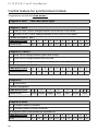
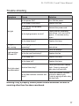
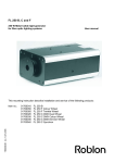
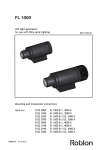
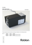
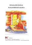
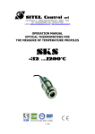
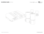
F L 7 5 X T- 2 B , F a n d C
Halogen light generator
for Roblon Fiber Optics exterior lighting systems
+99082045 rev. 2.0
This user manual describes the installation and service of
the following products :
EU
US
Product
01510350
01510250
FL 75 XT-2 B
01510351
01510251
FL 75 XT-2 F Colour Wheel
01510356
01510256
FL 75 XT-2 F Twinkle Wheel
01510353
01510253
FL 75 XT-2 C Synchron
01510355
01510255
FL 75 XT-2 C DMX Dual Wheel
01510352
01510252
FL 75 XT-2 C DMX Colour Wheel
01510354
01510254
FL 75 XT-2 C DMX Dimmer Wheel
Fuse
Colour or twinkle
wheel on/off*
230 V in
EU model
120 V in
US model
DMX in
Code wheel**
DMX out
Connection
board
Lamp
Hole for locking
light generator
on bracket or wall
Colour
wheel***
Dimmer
wheel**
Fan
* = only on F models,
** = only on DMX models
*** = only on F and DMX models
F L 7 5 X T - 2 B , F and C
Halogen light generator
for Roblon Fiber Optics exterior lighting systems
FL
FL 75 XT-2 B, F and C User Manual
Introduction
Your Roblon Fiber Optics halogen light generator, type FL 75 XT-2 is intended for
outdoor use in fiber optic lighting systems using either glass or PMMA fibers. The
halogen light generator has been developed to meet the requirements of a Roblon
fiber optic lighting system, where the light output intensity and efficiency is optimized in
order to ensure the best performance and safety.
This manual should serve as a guideline how the system is operated in the safest way.
Following the recommendations in this guideline all contributes to:
◦ Enhanced functionality
◦ Extended lifetime of components
◦ Uninterrupted system illumination
Contents
Product overview and packing list
4
Technical information
4
Installation instructions
5
Control feature for FL 75 XT-2 F
5
Mount the light generator
6
Mount the light generator on a wall
6
Mount the light generator on a mounting bracket
7
Remember
7
Air flow in tube
8
Change the lamp
9
Change the fuse
9
Change the fan
10
Stand alone mode for DMX models
11
Connecting for DMX models
12
Control features for DMX models
13
Control features for synchronized models
15
Trouble shooting
17
Spare parts
18
3
FL 75 XT-2 B, F and C User Manual
Product overview and packing list
Contents of this box:
1 light generator FL 75 XT-2 series
1 key
1 Allen key
4 mounting fittings
1 user manual
Screws for wall mounting
Technical information
Light port size
Ø9 / Ø28 mm.
Fiber type
PMMA / Glass.
Supply voltage
EU
US
230 V (nominal), 50-60 Hz
120 V, 60 Hz
Lamp
Philips 12 V, 75 W, 60 Hz
Power consumption
75 W
Fuse
2A
Power cord
Lead w / 3 conductors
Data connection
Screw terminals
Ballast
Electronic
Thermal protection
Auto reset
Cooling system
DC axial fan
Fan noise level
28.5 db(A)
Ambient temperature
-30° to 40°
Lamp type
Halogen
Lamp life time
6000 hour
Lamp colour temperature
3000 K
Material
Steel, electro galvanised and powder
coated
Dimensions
(L x W x H) 250 x 355 x 165 mm
Weight
9 kg
Safety approvals
CE, EMC comply, FCC comply, CB, CSA
Degree of protection
IP 45
4
FL 75 XT-2 B, F and C User Manual
Installation instructions
Unpack the unit, and make sure that the grounded power
supply cord is suitable for your country.
Use the key to open the door.
Insert the fiber harness’ commond end fully into the output
port of the light generator.
Tighten the grille screw with the supllied Allen key and mount
the plug in the hole.
Control feature for FL 75 XT-2 F (Not for US)
Colour or Twinkle wheel ON/OFF
SEE ILLUSTRATION ON PAGE 2
Extern ON/OFF wiring:
Blue: N
Brown: L1, lamp + fan
Black: L2, motor
Yellow/green
5
FL 75 XT-2 B, F and C User Manual
Mount the light generator
Important: Mount the light generator on a wall, place it on a mounting bracket, or lie it
on the back side of the light generator.
(Not IP 45 when placed on the back side)
Mount the light generator on a wall
Mark two holes with 130 mm in between.
Drill Ø8 mm holes.
Use rawplugs to mount the pins on the wall.
To lock the light generator to the wall: mark through the
hole in the bottom. Remove the light generator and drill Ø6
mm hole. Mount rawplugs in the hole.
SEE ILLUSTRATION ON PAGE 2
Place the light generator on the pins and mount the screw.
Mount the plug.
6
FL 75 XT-2 B, F and C User Manual
Mount the light generator on a mounting bracket
Place the mounting bracket.
Mount the light generator on the two pins.
Front
Back
Mount the screw M4 x 20 to secure the light generator.
Remember
150 mm
150 mm
The space between the light generator and larger items
must be more than 150 mm.
The light generator has to get the heat away from the
lamp.
Do not place two light generators on top of each other.
300 mm
Make sure that the hot air from one light generator does
not blow directly into the air intake of the light generator
next to it.
7
FL 75 XT-2 B, F and C User Manual
Airflowintube
Light generators needs to get fresh air to keep cool.
In small rooms it will be necessary to separate air intake and air exhaust. It can be
done with a tube.
The following shows how tube is mounted on the exhaust pipe.
Use a flex tube with a 70 - 75 mm internal opening. Max tube length 4 m.
Required air flow is ~30 m³/h per light generator.
Air intake
Air Exhaust
Remove the 3 screws from the box.
Remove the box and replace the screws.
Place the tube and tighten screw clamp.
8
FL 75 XT-2 B, F and C User Manual
Change the lamp
Turn off the light generator.
Open the door.
Release the lamp plug.
Remove the lamp.
The new lamp is installed in reverse order.
Change the fuse
Turn off the light generator.
Open the door and take out the fuse holder.
Change the fuse.
Mount the fuse holder.
SEE ILLUSTRATION ON PAGE 2
9
FL 75 XT-2 B, F and C User Manual
Change the fan
Turn off the light generator.
Release the fan plug.
Loosen screw.
Tip the bracket plate in the bottom, and remove the fan
from the light generator.
Remove the screws.
Install a new fan in reverse order.
Note the arrow showing the air flow through the fan. The
arrow must point out of the light generator.
After installing the fan, check the air flow.
The air has to blow out at the side where the fan is placed.
10
FL 75 XT-2 B, F and C User Manual
Stand alone mode for DMX models
Six built in programs for colour changing and choosing are available.
Code Wheel 1
9
The light generator is in stand alone mode.
Code Wheel 2
0-9
Varies the pauses between the changes.
0 is the shortest and 9 is the longest.
Code Wheel 3
0
Not used.
1
Fast colour change between all the colours of the wheel.
2
Smooth (5 sec.) colour change between all the colours of the wheel.
3
Smooth colour change between green and orange.
Colours change at 50% dimming (on models with dimming wheel).
4
Smooth colour change between blue and red.
Colours change at 50% dimming (on models with dimming wheel).
5
Smooth colour change between green, orange, blue, red, yellow
and backwards.
Colours change at 50% dimming (on models with dimming wheel).
6
Full colour. Use code wheel 2 to change colour.
1. White, 2. Green, 3. Orange, 4. Blue, 5. Red, and 6. Yellow.
7-9
Not used.
11
FL 75 XT-2 B, F and C User Manual
Connecting for DMX models
Connections with screw terminals.
Max signal cable length of the whole installation is 120 meters and max 30 DMX units.
Control unit
If there is more than one light generator they must be connected in a daisy chain
connection
Mount DMX the cable from a DMX controller to the IN
connection on the light generators DMX connection board.
SEE ILLUSTRATION
Mount the DMX cable in the first light generators OUT
connection to the light next generators IN connection.
See Fig 1!
In the last light generator there has to be a line termination
in the OUT connection(factory mounted).
See Fig 2!
Fig. 2
Fig. 1
Pin 2 Pin 3
data - data +
In
12
Shield
Pin 2
data -
Out
Pin 3
data +
Pin 2 Pin 3
data - data +
In
Shield
Line Termination
FL 75 XT-2 B, F and C User Manual
Control features for DMX models
1. Setting the DMX channel on the light generator
The light generator is normally using 3 DMX channels.
The first is set with the code wheels 1 - 2 - 3, between 001 and 512.
The next two will automatic be the two following DMX channels.
Example: If the code wheels are set to 016 then the two next will be 017 and 018.
Example: The DMX channel is set to 016
2. Set the DMX control feature.
When the DMX channel is set on the code wheel it is possible to set the three channels
on a DMX control feature like the Linebacker or Alcorn McBride:
Control: ( 1st channel) 5 sec. delay on all functions
000 - 018
Not assigned
019 - 039
Lamp OFF
040 - 050
Not assigned
051 - 070
Shortest mode
071 - 080
Not assigned
081 - 100
Linear mode
101 - 120
Not assigned
121 - 144
Reset colour and dimming wheels
145 - 160
Not assigned
161 - 179
Reset colour wheel
180 - 220
Not assigned
221 - 239
Lamp ON
240 - 255
Not assigned
13
FL 75 XT-2 B, F and C User Manual
Control feature for DMX models
Colour wheel: ( 2nd channel)
000 - 200
Position of colour wheel
201 - 205
Not assigned
206 - 230
Variable speed of rotation clockwise (1 rpm. on 217)
231 - 255
Variable speed of rotation counterclockwise (1 rpm. on 242)
Frames 1
through 6 at
Colour
000 200
033
067
100
133
167
White
Green
Orange
Blue
Red
Yellow
Dimming wheel: ( 3rd channel)
000 - 200
Position of dimming wheel (000 is black out, 167 is bright light)
201 - 205
Not assigned
206 - 230
Variable speed of rotation clockwise (1 rpm. on 217)
231 - 255
Variable speed of rotation counter clockwise (1 rpm. on 242)
Frames 1
through 6 at
Intensity
14
000 200
033
067
100
133
167
0%
6%
12%
25%
50%
100%
FL 75 XT-2 B, F and C User Manual
Control features for synchronized models
Controlling can be done by a master or a control unit.
Key features:
Selection of full colour
•
•
Selection of colour wheel rotation speed and direction.
Connect the synchron light generators into the line of light generators via a shielded
twisted pair type DMX cable.
(Slave)
(Slave)
(Slave)
(Slave)
Master
Slave
Slave
Slave
(Control unit)
Set the light generator as Master by setting the code wheel 3 to “9”.
Set all the connected Slave light generators to channel “800” and they will be
synchronized with your choise of program on the Master light generator or control unit that
should be set according to next page.
Master
Slave
8 built in standard programs for colour changing are available.
15
FL 75 XT-2 B, C and F User Manual
Control feature for synchronized models
Programs are set with the code wheel 1:
Program 0 and 7 - Not used (white light)
Program 1 and 2
1
Fast (0.2 sec.) colour change between all the colours of the wheel.
2
Smooth (5 sec.) colour change between all the colours of the wheel.
Pauses in program 1 and 2
0
1
2
3
4
5
6
7
8
9
0.8
1.7
2.5
3.3
4.2
5.0
5.8
6.7
7.5
8.3
Code wheel 2 pos.
Pause in sec.
Program 3, 4 and 5
3
Slow colour change between green and orange.
4
Slow colour change between blue and red.
5
Slow colour change between green, orange, blue, red, yellow and backwards.
Pauses in program 3, 4 and 5
0
1
2
3
4
5
6
7
8
9
7.5
10
12.5
15
17.5
20
22.5
25
27.5
30
Code wheel 2 pos.
Pause in sec.
Program 6
1
Fixed colour.
Colours in program 6
Code wheel 2 pos.
0
1
Pause in sec.
White
2
3
4
5
6
Green
Orange
Blue
Red
Yellow
7
8
9
white
Program 8 and 9
8
Constant rotation clockwise.
9
Constant rotation counter clockwise.
In programs 8 and 9 the speeds are equivalent to:
Code wheel 2 pos.
RPM
16
0
1
2
3
4
5
6
7
8
9
0.1
0.2
0.4
0.6
0.8
1.0
1.2
1.5
2.0
3.0
FL 75 XT-2 B, C and F User Manual
Trouble shooting
Symptom
Cause
Solution
Is the power ON?
Turn ON the power.
Is the supply fuse intact?
Replace the fuse.
Is the power cord properly
connected?
Reinsert the power cord.
Is the light generator too hot?
Check with the installation
instructions. Let it cool off for
approx. 15 minutes and try
again.
Is the lamp blown?
Replace the lamp.
No light
No light,
fan running
Light switches
ON and OFF
The light output
has diminished
Is the light generator too hot while Check with the installation
operating?
instructions.
Is the fan blocked?
Clear the airways.
Is the fan mal functioning?
Replace the fan.
Is the lamp old?
Replace the lamp.
Is the lamp old?
Replace the lamp.
Are the filters dirty?
Clean the filters with a damp
cloth. Finish by wiping off
with a dry lint-free cloth.
Is the fiber harness common end
dirty?
Clean the harness common
end with a damp cloth.
Finish by wiping off with a dry
lint-free cloth.
Warning! Only a properly trained person should undertake the work of
servicing other than the above mentioned.
17
FL 75 XT-2 B, F and C User Manual
Spare parts
Description
Model designation
Lamp
Philips 12 V, 75 W, 3000 K
6512 7595
Fan
Sunon KDE 1208PTB3-6
6408 0124
Yellow
Dichroic colour filter
Green
mounted in bracket
Blue
Red
Roblon item no.:
7800 0140
7800 0141
7800 0142
7800 0143
CTC filter
with bracket
CTC filter, -1200K
CTC filter, - 900K
CTC filter, - 500K
7800 0148
7800 0149
7800 0147
Colour wheel
Standard colour wheel
5100 0085
Dimmer wheel
Standard dimmer wheel
5100 0086
Mounting
Bracket
Galvanized steel
0160 0365
230 / 240 V
120 / 11.8 V
6815 0020
6810 5042
Stepper motor 1.8°
6400 4000
1 rpm 230 VAC
1.2 rpm 110 VAC
LineBacker
Alcorn McBride
Y-distributor in a DMX system
5 outputs
6400 1220
6400 1215
0160 0300
0160 0301
Electronic ballast
EU
US
Effect motor for
DMX models
Gear motor for
F models
EU
US
DMX 512
control units
DMX 512 Splitter
Synchron
control unit
Cable between DMX and Synchron
light generators.
DMX and Synchron Please state required length.
Cable
Cable between DMX / Synchron
control unit and light generators.
Please state required length.
18
0160 0310
0160 0325
9903 0055
9903 0060
Roblon accepts no responsibility for possible errors in printed and electronic material. Roblon
reserves the right to alter or discontinue products without notice. © 2012, Roblon A/S.
Roblon Lighting
Nordhavnsvej 1
9900 Frederikshavn
Denmark
Tel: +45 9620 3300
Fax: +45 9620 3399
[email protected]
www.roblon.com