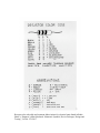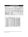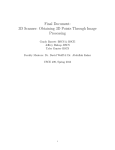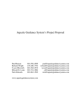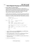
1
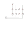
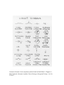
LAB L1b
Parallel Output Using Light Emitting Diodes
Objectives:
1. Learn which ports of the HCS12 can be used for digital input or output.
2. Write a program that will set a port to be an input or output. Also, learn how to set
an output port high (+5V) or low ( 0V).
3. Discover the relationship between program code and time required to execute a
program.
4. Learn how to connect low current devices such as light emitting diodes to the EVB.
Introduction
The purpose of this lab is to familiarize the student with techniques used in interfacing
the HCS12 with the outside world. Specifically, the parallel input/output feature of the
HCS12 will be used to illuminate a series of four light emitting diodes in a desired
sequence.
Parallel Input/Output Communication
Parallel I/O (Input/Output) is the transmission of several bits of data at the same time
between the HCS12 and a sending or receiving device, such as a PC. (Serial I/O is
essentially the transmission of a single bit at a time over a single wire.) Parallel I/O data
is most commonly transmitted one byte (8-bits) or one nibble (4-bits) at a time. Ports A
and B on the HCS12 are specifically designed to transmit parallel data. However, on the
CML-12C32, these two ports are used to interface with the external RAM chips. In this
lab, port P will be used for signal transmission.
Software
All I/O in the HCS12 is controlled by a set of registers that reside in locations
$0000-$03FF. The three register types are: data registers, data direction registers, and
control registers. Data registers hold the data going in or coming out of the HCS12. Data
direction registers (DDR's) control the direction (input or output) of the data. Control
registers control the mode of operation of the data registers. Each bit in each of these
registers has a specific purpose, and can be accessed by reading or writing to the register
in the same manner as reading or writing to any other memory location. The complete
register set, along with the control bit assignments, can be found in the MC9S12C Family
Reference Manual, S12CPUV2 reference manual and the CPU12 Reference Guide.
The Port P (PTP is its name) data register is located at addresses $0258. This is the
address where the data to be output is stored. The data direction register for port P is
located at address $025A (DDRP is the register name). This register is an 8-bit register
that determines the direction of the data flow (whether it is input data or output data) for
each pin of port P. Writing a 1 to a given bit in the DDRP sets up the corresponding pin
on port P for output (or 1 for output). Writing a 0 to a given bit in the DDRP sets up the
corresponding pin on port P for input (or 0 for input).
Hardware Components
The MCU_PORT port connector on the EVB is used to interface the HCS12 with the
outside world. This connector consists of 60 pins that are associated with the HCS12 I/O
features. Pin assignments for the connector can be found CML-12C32 User's Manual.
The bread-board or proto-board simplifies the circuit evaluation (testing) process by
allowing the user to simply plug the components into the board to make the desired
connection(s), as opposed to soldering or wire-wrapping the components together.
Although one may use the bread-board for testing purposes, soldered, printed circuit
board (PCB), components would always be the preferred approach when the same circuit
is to be used repeatedly over a long period of time. The bread-board is acceptable for any
work performed in this course. Breadboards consist of a series of interconnected holes
which are spaced at 0.10" apart. This 0.10" spacing is consistent with the pin spacing on
the majority of all integrated circuits (IC's or chips). To make connections between
electronic components on the bread-board, as well as between the 60 pin connector and
the bread-board, it is recommended that 22 gage wire be used.
Resistor Even though resistors are available in numerous shapes and sizes, they all do the
same thing, which is to limit (or resist) current. Physically, a typical carbon composition
resistor consists of the carbon composition which is contained in a protective housing
(usually somewhat cylindrical in shape), and two wire leads which extend out from both
ends of the housing. On the outside of the housing color coded bands are present which
indicate the resistance of the resistor. By changing the carbon content of the resistor the
resistance is changed. More carbon means less resistance.
The color band decoders (a table with one column of colors, and three to four columns of
numbers) can be found in the L1 appendix and in almost any book on electronics. To
determine the resistance of a resistor using the color code table perform the following
steps: A) Orient the resistor so that the band closest to the end of the housing is to your
left. B) Find the band color (say this color is yellow) in the color code table. C) The first
column of numbers represents the number associated with the far left band. Find and
record this number (which would be the number 4). D) The second band from the left is
represented by the second column of numbers. Find this band's color (say this color is
blue) and associated number from the table (which would be the number 6). Append this
number to the right of the first number that was written down (we now have the number
46). E) The third band from the left is represented by the third column of numbers, which
represents the multiplier. Find this band's color (say this band is orange) and its
associated multiplier number (which would be 1,000) from the table. F) Multiply the
number found in step D by the multiplier found in step E (46 x 1,000 = 46,000 or 46k
Ohms). If the resistor has no fourth band, then the accuracy of this resistor is +/-20% or
+/-9.2k Ohms. This means that the value of this resistor can be anywhere between 36.8k
and 55.2k Ohms. If the fourth band is silver, then the accuracy of this resistor is +/-10%
or +/-4.6k Ohms. And if the fourth band is gold, then the accuracy of this resistor is
+/-5% or +/-2.3k Ohms. The higher the accuracy the higher the resistor cost.
The power rating for a given resistor indicates the maximum amount of power a resistor
can dissipate. This dissipated power will be noticeable in the form of heat coming from
the resistor (they will turn black and smoke if the power rating is to low for the
application). The most common resistor power ratings are 1/4 and 1/2 Watt. Use P = i2R
(discussed below) to determine the correct rating for your application. If your application
calls for a resistor with a rating within 10% of 1/4 Watt, go to the 1/2 Watt rated resistor
to allow for a factor of safety.
Diode The diode is constructed from both P-type (more holes) and N-type (more
electrons) silicon. Both P- and N-types of silicon conduct electricity, and their resistance
to current flow is determined by the proportion of holes or surplus electrons. A chip
consisting of a small amount of P-type silicon bonded to a larger amount of N-type
silicon, forms a chip that will allow current to flow in only one direction. The P-N
interface is called the PN junction.
If the chip is placed in series with a battery, with the P side of the PN junction closest to
the positive side of the battery, and the N side of the PN junction closest to the negative
side of the battery, the diode is said to be forward biased. In this case the charge from the
battery repels the holes (P-side) and the electrons (N-side) toward the PN junction. If the
voltage across the diode (in this case the voltage of the battery) exceeds a given threshold
(0.6 V for most silicon diodes, 1.3 V for most light emitting diodes) a current will flow
across the PN junction from the P side to the N side of the junction (the direction of the
current flow opposes that of the electron flow). The diode can be damaged if the forward
current is excessive, which will cause the diode to get very hot to the touch, and
eventually melt.
If the same chip is placed in series with the same battery, only this time with the N side of
the PN junction closest to the positive side of the battery, and the P side of the PN
junction closest to the negative side of the battery, the diode is said to be reverse biased.
In this case the charge from the battery attracts the holes (P-side) and the electrons
(N-side) away from the PN junction, therefore, no current will flow. If the reverse bias
voltage is continuously increased, a voltage level will be reached which will cause the
diode to conduct current in the undesired direction. The voltage level at which this occurs
is termed the breakdown voltage of the diode. This breakdown voltage will damage the
diode. The breakdown voltage is specified by the manufacturer of the diode. If excessive
reverse bias voltage is applied the diode may audibly "pop." Current vs. voltage plots for
a given diode can be obtained from the manufacturer.
Light Emitting Diode (LED) The operating principal of the LED is the same as the diode
except that when the threshold voltage (usually 1.3 Volts) is exceeded, electrons in the
Gallium-Arsenide are excited. These excited electrons produce photons which emit light
at a given wavelength. Common LED's are available in wavelengths from 565 nm (green)
through 880 nm (infrared). The light emitted by a LED is directly proportional to the
current being passed through the LED. As with standard diodes, excess current will
overheat and damage the LED. Since LED's are current dependent, they usually require a
series resistor. Determination of the necessary resistor size is discussed below in the
analysis tools section.
Physically, the LED is composed of 5 main components: the LED chip, reflector, epoxy,
and cathode and anode leads. The LED chip is usually a PN junction type diode. The
reflector collects the light emitted from the edges of the chip and reflects the light to the
epoxy housing, through which the light is dispersed. The cathode lead is the negative side,
and the anode is the positive side of the LED. The cathode lead is closest to the flat edge
on the epoxy housing's base.
Multimeters The multimeter's primary functions are to measure dc and ac voltages and
currents, as well as resistance. Multimeters are available with both analog (needle) and
digital output displays. Prior to making measurements turn the meter on and check the
battery. On the analog type meters, when a resistance range is selected, the needle will
not deflect when the leads are touched if the battery is low. On the digital type meters, a
BAT light will illuminate when the battery is low.
Voltage measurements:
1) Plug the leads into the correct jacks on the meter (one lead into the "COM" (for
common or more negative side) jack, and the other into the V (for Volts) jack.
2) Set the voltage range (dc or ac). If you are not sure what voltage is expected, then use
the highest range position.
3) Touch the probe tips to the circuit under test.
4) Read the voltage.
5) Turn the meter off to conserve the battery.
Current measurements:
1) Plug the leads into the correct jacks on the meter (one lead into the "COM" (for
common or more negative side) jack, and the other into the A (for Amperes) jack.
2) Set the amperage range. If you are not sure what amperage is expected, then use the
highest range position.
3) Turn power off to the circuit under test.
4) Open the circuit.
5) Apply power to the circuit under test.
6) Touch the probe at the two nodes where the circuit was opened.
7) Read the amperage.
8) Turn power off to the circuit under test.
9) Turn the meter off to conserve the battery.
Resistance measurements:
1) Plug the leads into the correct jacks on the meter (one lead into the "COM" (for
common or more negative side) jack, and the other into the Ω (for Ohms) jack.
2) Set the resistance range. If you are not sure what resistance is expected, then use the
highest range position.
3) Touch the probe tips together. A value of zero resistance should be indicated. (On
analog meters the zero position may have to be calibrated to zero using the "Ohms
Adjust" wheel on the front panel.)
4) Touch the probe tips to the circuit under test. (Keep in mind the possible paths of
resistance.)
5) Read the resistance.
6) Turn the meter off to conserve the battery.
Definitions
Diagram L1CIR shows the circuit connections that are required for the lab. This diagram
shows a +5 V connection to 4 resistor/diode pairs, which are connected to the pins PTP2,
PTP3, PTP4, and PTP5. Prior to immediately answering the requirements below, the
following electrical definitions and discussion may be helpful. Since all the I/O using the
HCS12 in the course required labs use direct current (dc) electricity, the following
definitions and discussion will be limited to dc electricity.
Voltage, voltage drop, or potential These refer to a difference in charge between two
points, say A and B. If point A has a greater (+) charge than point B, then point A has
fewer electrons than point B (recall that electrons have a negative charge). Or, put
another way, point B has a greater number of electrons than point A. If we define ground
(simply a reference point or state) to have even more electrons than point B (more
negatively charged than point B), then point A is said to have a greater potential than
point B. This is analogous to potential energy where the greater the distance an object has
from the ground, the greater its potential energy. Notice that we defined ground. In a dc
electronic circuit, ground refers to the zero voltage point. This zero voltage point is
usually taken to be the negative or "minus" side of the battery powering the circuit. If a
point has fewer electrons (more positive) than the defined ground, then that point is said
to have a positive voltage (+V) relative to ground. If a point has a greater number
electrons (more negative) than the defined ground than that point is said to have a
negative voltage (-V) relative to ground. Voltage drop is the difference in voltage
between a positively charged point and a less positively (more negative) charged point
(the drop from the positive to the negative, or the drop in potential). The unit of voltage is
the Volt (V). In SI units, 1 Volt is equal to 1 Joule/Coulomb, or 1 V = 1 J/C. (Recall that
the Joule is a unit of work which is equivalent to 1 Newton-meter, or 1 J = 1 N-m.)
Current Current refers to the flow of electrons in a conductor. Current flow is always
from a more positively charged point to a less positively charged (more negative) point.
The flow of electrons is always from a more negatively charged point to a less negatively
charged (more positive) point. Therefore, current flow (direction) opposes electron flow
(direction). Current is analogous to kinetic energy. From the above voltage analogy to
potential energy, it can be seen that the greater the difference in voltage between two
points on a conductor, means a greater current between these two points. This is
analogous to an object held above the ground. The greater the objects height (potential)
above the ground, the greater the kinetic energy just before it hits the ground (neglecting
aerodynamics forces of course). DC current refers to current that only flows (in steady or
pulse form) in one direction between two points. The unit of current is the Ampere (A).
In SI units, the Ampere is a base unit. (Recall that a Coulomb is defined as the amount of
charge that flows through any cross section of a wire in one second if there is a steady
current of one Ampere in the wire, or q = it, where q is in Coulombs, i is in Amperes, and
t is in seconds.)
Resistance In electronics this refers to the resistance of current through a conductor. All
conductors have some resistance. A potential difference of 1 Volt will force a current of 1
Ampere through a resistance of 1 Ohm (Ω). The unit of resistance is the Ohm. In SI units,
the resistance of a conductor is defined as Volts per current, or R = V/i, where R is in
Ohm's, V is in Volts, and i is in Amperes.
Ohm's law Voltage is linearly related to the current through the resistance. Voltage is
equal to the current times the resistance, or V = iR, where i is in Amperes (A), and R is in
Ohm's (Ω).
Power The work performed by an electrical current. The power of a direct current is
equal to the current times its voltage, or P = iV, or using Ohm's law: P = i2R. This
relationship will become important when determining what power rating should be used
for a resistor, for example. The unit of power is the Watt (W). In SI units, one Watt is
equivalent to one Joule/second, or 1 W = 1 J/s.
Analysis Tools
Recall that the total resistance of any number of resistors connected in series is the sum of
the individual resistance's or
RTotal = R1 + R2 + … + RN
(Resistors in series).
Recall that the total resistance of any number of resistors connected in parallel is 1
divided by the sum of the reciprocals of the individual resistance's or
RTotal = 1 / (1/R1 + 1/R2 + … +1/RN)
(Resistors in parallel)
Another useful analysis tool is voltage division. For example, if a battery with voltage Vin
is in series with two series resistors, R1 and R2, the voltage Vout between the two resistors
(assuming that R2 is closest to the positive side of the battery) is given by
Vout = VinR2/(R1 + R2)
(Voltage division)
To determine the series resistor required for an LED, the following equation can be used,
which can be derived from Kirchoff's voltage law (KVL), where Rs is the required series
resistance, Vsup is the voltage difference across the LED, VLED is the threshold voltage for
the given LED, and ILED is the desired current through the LED.
Rs = (Vsup - VLED)/ILED
Requirement 1B.1
Connect the 4 LED's to the pins PTP2 through PTP5 of the HCS12. It should be noted
that the circuit as shown in L1CIR will cause the LED's to light when PTP2 through
PTP5 are set low and extinguish when PTP2 through PTP5 are set high. Explain why this
occurs. The lab instructor will specify a lighting sequence for the student to implement.
Requirement 1B.2
Answer the following questions, using examples when possible.
1B.21 Demonstrate your working program to the TA.
1B.22 How does the HCS12 communicate with the rest of the EVB and with the outside
world? Be sure to discuss the different communication modes.
1B.23 Which ports on the HCS12 can be configured for Input, Output, Input/Output?
How is a port configured for Input? How is a port configured for Output?
1B.24 What is special about port AD?
1B.25 Discuss the different methods for creating time delays in HCS12 programs.
1B.26 Your report should include a well documented listing of your program (with a title
block listing your name, lab number, and date), the *.LST file, and any necessary
calculations.
References
Georgia Institute of Technology, George W. Woodruff School of Mechanical
Engineering, “ME4447: Control System Components, Laboratory Manual”, 1989.
Greenfield, J.D., “The 68HCS12 Microcontroller”, Saunders College Publishing, 1991.
Halliday, D., Resnick, R., “Fundamentals of Physics”, 2nd Ed., John Wiley & Sons,
1981.
Mimms, F.M., “Engineers Mini Notebook: Optoelectronic Circuits”, Radio Shack, Cat.
No. 276-5012A, 1986.
Motorola, “MC9S12C Family Reference Manual”, Motorola, Inc., Rev. 01.23, 2007.
Motorola, “MC9S12C Programming Reference Guide”, Motorola, Inc. , 2001.
Diagram L1CIR
Common electronic circuit component symbols found in Radio Shack’s “Engineer’s
Mini-Notebook: Schematic Symbols, Device Packages, Design and Testing”, Cat. No.
276-5017.
Resistor color code table and common abbreviations for electrical units found in Radio
Shack’s “Engineer’s Mini-Notebook: Schematic Symbols, Device Packages, Design and
Testing”, Cat.No. 276-5017.
Typical resistor data sheet found in Digi-Key Corporation’s catalog number 961,
January-February 1996.