1
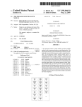
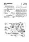
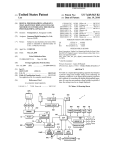
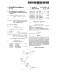
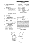
US007623025B2
(12) Ulllted States Patent
(10) Patent N0.:
Miller
(54)
US 7,623,025 B2
(45) Date of Patent:
TIRE PRESSURE MONITOR INITIATION
TOOL WITH VEHICLE DATA INTERFACE
(75) Inventor:
6,662,642 B2
Nov. 24, 2009
12/2003 Breed et a1.
Garret Miller, OWatonna, MN (US)
(Continued)
(73) Assignee: SPX Corporation, Charlotte, NC (US)
FOREIGN PATENT DOCUMENTS
(*)
Notice:
Subject to any disclaimer, the term of this
patent is extended or adjusted under 35
EP
1026015 A2
8/2000
U.S.C. 154(b) by 212 days.
(21) App1.No.: 11/589,091
(22) Filed:
(Continued)
Oct. 30, 2006
OTHER PUBLICATIONS
(65)
Prior Publication Data
Bartec Auto ID LimitediActivation T001 BXRZOOOAI, Bartec Auto
Us Zoos/0103718 A1
May 1, 2008
ID Activation T001 (Sep. 3, 2001).
(51) Int- Cl-
(Continued)
B60C 23/00
(52)
(58)
(2006.01)
us. Cl. .............. .. 340/426.33; 73/1462; 116/34 R
Field of Classi?cation Search .......... .. 340/426.33,
Primary ExamineriGeorge/A Bugg
(74) Alwmey Agenl, 0r FirmiBake/r & Hoste?er LLP
340/438, 4424449; 116/34 R, 34 A; 73/146,
73/1462
See application ?le for complete search history.
(57)
(56)
References Cited
A tire pressure monitor system tool stores information
regarding a plurality of tire pressure monitor systems
U.S. PATENT DOCUMENTS
5,124,410 A
installed on Vehicles. The tool receives information regarding
a particular Vehicle. Based on this information, the tool may
6/1992 Campbell
5’462’374 A
10/1995 Kohno
5,562,782 A
10/1996
5,562,787 A
10/1996 Koch et 31‘
ABSTRACT
determine a articular tire ressure monitor s stem installed
Takahashi
_
P
P
_
y
_
'on a Vehicle. Based on the tire pressure mon1tor system
5,600,301 A
2/ 1997 Robinson, 111
1nstalled on the Vehicle, the tool may determ1ne one or more
5,602,301 A
2/ 1997 Field
procedures that may be used With that tire pressure monitor
5,602,524 A
2/ 1997 Mock et a1~
system. The tool may then instruct a user hoW to perform
5173115 16 A
3/1998 Haee?eld et a1‘
certain procedures by presenting one or more displays to the
5,952,935 A
9/1999 Mejla et a1.
6,172,609
6,243,007
6,340,929
6,414,592
6,438,467
6,441,727
B1
B1
B1
B1
B1
B1
6,617,962 B1
6,630,885 B2 *
M2001
60001
1/2002
7/2002
8/2002
8/2002
.
Lu et 31‘
McLaughlin et a1‘
Katou et a1,
Dixit et a1.
Pacsai
LeMense
.
user on a display of the tool. The tool may also provide
feedback to the user regarding a status of an initiation or other
procedure, and reference a Veh1cle user manual. The tool may
interface With an electronic control unit of a Vehicle. The tool
may also simulate a tire pressure sensor.
9/2003 HorWitZ et a1.
10/2003 Hardman et a1. .......... .. 340/505
TPMS
iciulg
e i
8
ate
‘95385109
. ,
Linking
I
Module
55
Procedure
1%]?
Re'?g?n
Module g
1
.
.
8 In
Simulsli'ng
M13119
‘
lnihat'
D‘agnosmg
i
Mod
Module
72
‘ Resetting ‘
Vehicle ECU
Feedback
lnlerfacing
Providing
Module
52
Module
7B
5
,
DMzldzzleg
Transmittlng
M
.
Beginning
Procedure
Accessing
M?sdsllle
I
59 Claims, 8 Drawing Sheets
as
Module
14
19
US 7,623,025 B2
Page 2
US. PATENT DOCUMENTS
6,864,785 B2
6,904,796 B2
6,945,087 B2
3/2005 Marguet et a1.
6/2005 Pacsai et a1.
9/2005 Porter et a1.
FOREIGN PATENT DOCUMENTS
EP
GB
GB
1092568 A2
2305074 A
2308947 A
4/2001
3/1997
7/1997
6,989,741 B2
1/2006 Kenny et a1.
7,053,761 B2 *
5/2006 Sch(l)?eld et a1. .......... .. 340/447
Banec Auto ID LimitediBXR LHFiZOOO User Manual, Banec
7,075,421 B1
7,161,476 B2 *
7,319,848 B2 *
7 2006 Tutt e ....................... .. 340 449
1/2007 Hardman et a1. .......... .. 340/442
1/2008 Obradovich et a1. ........ .. 455/99
Auto IDiBXR LHF zoooiRange of Rugged Hand Held TPMS
Readers (Aug, 2002),
“Multi Standard Reader Product Range4overview of Product
9/2002
5 /2003
7/2003
2/2004
Range”, id Systems Ltd. (undated document).
“Market demands RF/ID standardization”, id Systems Ltd. (undated
document)
* cited by examiner
2002/ 0130771
2003/0080862
2003/0121320
2004/0036595
A1
A1
A1
A1
Osborne et a1.
Kmnz
Okubo
Kenny et a1.
OTHER PUBLICATIONS
US. Patent
10Xv
Nov. 24, 2009
Sheet 1 0f 8
US 7,623,025 B2
12
12
28
14
20
18
QQEE
\
1O
16b
16a
26
FIG. 1
FIG. 2
US. Patent
Nov. 24, 2009
620m >396
Sheet 2 of8
62 m 2 5m
ow
‘3620
52.80%
.wEcmC
US 7,623,025 B2
Nv
3,
.QEm
mm
6380592
mm
2t0o8m: 2
umg x
om
hoxmnw
vm
mm
US. Patent
Nov. 24, 2009
.
Sheet 3 of8
TPMS
Storing
Determining
Module
0
Module
Vehicle Data
Procedure
Requesting
Determining
Module
MOdUle
52
66
R
.
.
ecelvlng
Module
54
A
US 7,623,025 B2
_
Procedure
.
.
Displaying
Module
Notifyin
M d I9
O ue
80
_
Selecting
Updating
Module
68
Module
82
Manual
.
.
ccessmg
Referencing
Simulating
Module
56
Module
70
Module
84
Linking
Initiating
Diagnosing
Module
58
Module
72
Module
86
Transmitting
Resetting
Module
60
Module
74
E
Vehicle ECU
Feedback
Interfacing
Providing
Module
62
Module
76
FIG. 4
US. Patent
Nov. 24, 2009
Sheet 4 0f 8
Store Information
US 7,623,025 B2
102
1
Request Vehicle Data
104
Receive Vehicle Data
106
Access Information Stored
108
Link Vehicle Data and
Information Stored
110
Communicate Vl?th Vehicle ECU
112
Determine TPMS
114
1
Determine Procedure
116
1
Select Procedure
FIG. 5
118
US. Patent
Nov. 24, 2009
Sheet 5 0f 8
US 7,623,025 B2
Reference Owner's Manual
120
Initiate Sensor(s)
122
Provide Feedback
124
1
Display Information
126
Provide Noti?cation
128
Update Information Stored
130
V
Simulate Sensor(s)
132
Diagnose TPMS
134
FIG. 6
US. Patent
Nov. 24, 2009
Sheet 6 of8
US 7,623,025 B2
Product Name/Logo
Title Area - 158
152
Main Menu — 178a
Acura - 178!)
Audi -O17s<:
Other Information - 154
l_7§
O
O
Unlisted — 178n
11)‘
A
Enter
l
|
I
l
162
FIG‘ 7
V
166
FIG. 10
16:4
Title Area - 158
Title Area - 158
Reset - 160a
_
Main Menu — 182a
Diagnostics —160b
156
GT5 — 182b
DeVillg- 182a
Update — 160a
1 80
O
Unlistgd —182n
A
Enter
|
l
V
A
Enter
I
I
I
i
166
164
|
|
l
1
162
166
164
162
|:|G_ 8
V
FIG. 11
Current Vehicle
Title Area - 158
'
Main Menu — 186a
2005 Cadillac Escalade EXT
2006_186b
2005 —186c
170
m
8
O
Unlisted —186n
M
Reuse
172
|=|G_ 9
New
174
A
Enter
l
I
l
|
|
l
166
164
162
FIG. 12
V
US. Patent
Nov. 24, 2009
Sheet 7 0f 8
US 7,623,025 B2
Title Area - 158
Text Area - 190
Text Area - 190
Main Menu
Q
Next
E
Next
I
1
192
194
194
FIG. 13
FIG. 1 5
Text Area - 190
@
Text Area - 190
2 2
22¢
_L CD
ICO
Start
R
F
j
—
_ T’)
g 2. :s g (D 3 c
L
F
Mam Menu
198
j
L
R
R
R
1
|
192
204
192
FIG. 1 6
US. Patent
Nov. 24, 2009
Sheet 8 0f 8
US 7,623,025 B2
'|
218__\é Y A lD:1234567 190
Text Area - 190
>\
PSI: 32.3
g1_4 216
E
Main Menu
Yes
No
i
I
r
192
208
210
'
I
i
Main Menu
i'
192
FIG. 17
Learn Mode
Activate
||
220
FIG. 19
k
Text Area - 190
218——\@/
ID: 1234567
g\
222—@
Main Menu
PSI: 32.3
6 Learn Mode
i
Main Menu
192
i
I
192
ZZIO
FIG. 18
Activate
FIG. 20
190
US 7,623,025 B2
1
2
TIRE PRESSURE MONITOR INITIATION
TOOL WITH VEHICLE DATA INTERFACE
cation and location information regarding the tire must be
provided or “taught” to the ECU.
In order to accomplish the “teaching” of the tire identi?
RELATED APPLICATIONS
cation information to a vehicle-based portion, one known tire
identi?cation system is placed in a “learn” mode via actuation
of pushbutton(s) on an operator-accessible information panel
This application is related to co-pending US. patent appli
cation titled “Tire Pressure Monitor System Tool With
of the vehicle-based portion. During the learn mode, the
Vehicle Entry System,” ?led concurrently herewith, co-pend
vehicle-based portion is in a ready state to receive a distinc
ing US. patent application titled “Tire Pressure Monitor Sys
tem Module,” ?led concurrently herewith, and co-pending
US. patent application titled “Tire Pressure Monitor System
tive “learn” mode signal transmitted from each of tire-based
transmitter of the system. In order to cause each tire-based
transmitter to send the “learn” mode signal, a strong magnet
is swept over the outside of the associated vehicle tire.
A monitor is located at each tire and periodically takes a
measurement of the tire pressure. A pressure signal is gener
ated that corresponds to the pressure within the tire. The
monitor transmits the measurement in a radio frequency
transmission to the central monitoring station that produces
Tool With Re-Learn and Diagnostic Procedures,” ?led con
currently herewith, each of which is incorporated herein by
reference in its entirety.
FIELD OF THE INVENTION
The invention relates generally to tire pressure monitor
systems. More particularly, the invention relates to a hand
held tire pressure monitor system tool that interfaces with a
vehicle electronic control unit.
an alarm or a display in response to the measurement. When
20
the tire pressure drops below a predetermined pressure, an
indicator is used to signal the vehicle operator of the low
pressure.
During assembly and routine maintenance such as tire
rotation or tire replacement, the tire pressure system must be
BACKGROUND OF THE INVENTION
calibrated. Calibration involves associating the various tire
Systems have been developed to monitor, for example,
25
vehicle tire pressure, and to report the tire pressure to a
receiver at a central monitoring station using radio transmis
sions. A typical remote automotive tire condition monitoring
system includes a plurality of tire-based sensory transponders
and a central, vehicle-based arrangement. The sensory tran
positions with the pressure transmitters that are located on the
tires. One proposed method for calibrating a system uses a
magnet device to initiate the calibration. In this system, an
internal display panel with locations corresponding to the tire
30
sponders include a component that senses a tire condition,
such as tire in?ation pressure or tire temperature. Each tran
location is activated. When the tire locations are illuminated
on the display, the vehicle operator or service technician
places the magnet near the indicated tire. The transducer then
sends a code corresponding thereto to the central controller.
sponder is capable of outputting a coded transmission that
When the indicator indicates another tire location, the magnet
conveys sensed tire condition information and an identi?er
must be brought near each tire location until each of the tire
locations have a tire registered thereto. One problem with this
device is that a separate component such as a magnet must be
for reception by the vehicle-based arrangement. Within the
35
vehicle-based arrangement, an electronic control unit
(“ECU”) processes the conveyed information and controls
provision of information regarding the sensed tire conditions
to a vehicle operator. During operation of such a system, the
vehicle operator is readily noti?ed of a current tire condition,
40
such as a low in?ation pressure in a tire.
For a vehicle operator to determine which tire has a con
dition of interest (e.g., a low in?ation pressure), information
provided to the vehicle operator must unambiguously iden
tify the location (e.g., right front) of the tire that has the
condition of interest. In order for the ECU to provide such tire
45
preferably activated to produce this information and the infor
mation is conveyed to the central station and associated with
the position of the tire.
location information, the ECU has a memory that stores tire
50
In one technique, the tire monitors include a reed switch or
55
other magnetic device. A magnet is passed near the reed
switch causing the monitor to transmit a radio frequency
transmission that includes identi?cation data. A service tech
nician repeats this process at each wheel and then loads the
identi?cation and position information into the central moni
with the provided tire condition information. Accordingly,
the operator is made aware that the tire at a certain location
(e. g., right front) has the certain condition (e.g., low in?ation
pressure).
toring station.
Changes routinely occur regarding the tires and/or tran
One drawback with such a system is that because many
wheels are made from steel which is a magnetic material, tire
sponders that are associated with a vehicle. The changes can
result in new, different transponders being associated with the
vehicle, or a rearrangement of the locations of the transpon
60
ders, via rearrangement of the tires. Examples of such
sponders are mounted on a vehicle (e. g., the placement of the
initial set of tires during vehicle manufacture or replacement
tire. It should be readily apparent that new/modi?ed identi?
pressure sensing systems may not operate properly because
the steel wheels may shield the magnetic energy. Therefore,
the system may also be rendered inoperable because the pres
sure transmitter is not activated by the magnet.
Various tire manufacturers have suggested various loca
changes occur when one or more new tires with new tran
of one or more tires), when the tires are rotated during routine
maintenance, or when a transponder is replaced on an existing
alarm. Each monitor includes identi?cation information that
can be transmitted with the measurement. The tire monitor is
identi?cation information for comparison with the identi?ca
tion conveyed from the transponder. Also, within the memory,
a certain tire location is associated with each stored tire iden
ti?cation. Thus, once a provided identi?cation is matched to
a stored identi?cation, a location on the vehicle is associated
provided to the vehicle operator that is used only in the
calibration process. One problem associated with a separate
magnet device is that such a device is subject to loss. Thus, the
tire pressure sensing system would be rendered inoperable.
One problem with such systems is the need to program the
location of the transmitters at the central station. To be useful,
the tire pressure is preferably associated with the tire which
originated the measurement when presenting a display or
65
tions for the pressure sensors. Known systems include cou
pling a pressure sensor to the valve stem of the tire. Other
known systems and proposed systems locate the pressure
sensors in various locations within the tire wall or tread.
US 7,623,025 B2
3
4
These previous techniques have been limited in effective
ness. The magnetic programming technique may be subject to
interference and crosstalk, for example in a factory Where
many such tire monitors are being assembled With tires and
vehicles. Also, users of modular products are required to
purchase a separate tool to interface With tire pressure moni
tor systems.
described in terms of a plurality of modules, it is to be under
stood that the invention may be implemented using one or
more modules. Also, it is to be understood that the phraseol
ogy and terminology employed herein, as Well as the abstract,
are for the purpose of description and should not be regarded
as limiting.
As such, those skilled in the art Will appreciate that the
SUMMARY OF THE INVENTION
be utiliZed as a basis for the designing of other structures,
conception upon Which this disclosure is based may readily
methods and systems for carrying out the several purposes of
the present invention. It is important, therefore, that the
claims be regarded as including such equivalent constructions
insofar as they do not depart from the spirit and scope of the
present invention.
In accordance With one embodiment of the invention, a tire
pressure monitor system tool is provided that combines vari
ous tire pressure sensor initiation functions With a vehicle
data stream interface. The tool may store information regard
ing a plurality of tire pressure monitor systems that may be
installed on one or more vehicles. The information may iden
BRIEF DESCRIPTION OF THE DRAWINGS
tify, for example, initiation procedures that may be used With
a particular tire pressure monitor system and the tire pressure
monitor systems installed on particular vehicles. The tool
receives information regarding a particular vehicle. The
FIG. 1 is a front perspective vieW of a tire pressure mount
ing tool according to one embodiment of the invention.
20
information may be, for example, make, model, and year
FIG. 2 is a rear vieW of a tire pressure monitor tool accord
the tire pressure monitor system of the vehicle by presenting
ing to one embodiment of the invention.
FIG. 3 is a block diagram of a tire pressure monitor tool
according to one embodiment of the invention.
FIG. 4 is a block diagram of a tire pressure monitor tool
according to one embodiment of the invention.
FIGS. 5 and 6 illustrate a method of communicating With a
tire pressure monitor system of a vehicle according to one
embodiment of the invention.
FIGS. 7-9 illustrate initial screens that may be displayed by
a tire pressure monitor tool according to one embodiment of
one or more displays to the user on a display of the tool. The
the invention.
information. Based on this information, the tool may deter
mine a particular tire pressure monitor system installed on a
vehicle that has data matching the information. Based on the
tire pressure monitor system installed on the vehicle, the tool
25
may determine one or more initiation procedures that may be
used With that tire pressure monitor system.
The tool may have the one or more initiation procedures
stored by a storing module provided in the tool. The tool may
then instruct a vehicle technician or other user hoW to initiate 30
displays may provide step -by-step instructions regarding hoW
to initiate the tire pressure monitor system of the vehicle. The
tool may also provide feedback to the user regarding a status
35
of an initiation or other procedure, and reference a vehicle
user manual.
In accordance With another embodiment of the invention,
one embodiment of the invention.
the tool may interface With an electronic control unit of a
vehicle. This may be useful, for example, for diagnosing
problems With a tire pressure monitor system. By interfacing
With the electronic control unit, the tool may determine a tire
pressure monitor system installed on the vehicle, use func
tions of the electronic control unit to analyZe a tire pressure
monitor system, and provide notice to a user regarding
40
FIG. 1 illustrates a tire pressure monitor tool 10 according
45
antenna 12, display 14, selector button 16a-16c, port 18, a
poWer button 20, a casing 22, and passages 24. The antenna 12
may be used to transmit signals from the tool 10 to an elec
the electronic control unit of the vehicle, the tool may cause a
vehicle horn to sound or one or more lights to ?ash to indicate
that a procedure has been successfully completed. Addition
50
tronic control unit of a vehicle and a tire pressure sensor
mounted, for example, on a rim or tire of a vehicle. The
display 14 may be used to display information to a user
regarding, for example, the tool 10, a tire pressure monitor
nicate With the electronic control unit of the vehicle to deter
mine Whether a tire pressure sensor is fully operational.
system of a vehicle or status information regarding a resetting
or diagnostic function of the tool 10. The selector buttons
There has thus been outlined, rather broadly, certain
16a-16c may be used to navigate through the displays pre
embodiments of the invention in order that the detailed
description thereof herein may be better understood, and in
DETAILED DESCRIPTION
to one embodiment of the invention. The tool 10 includes an
completion of a procedure. For example, by interfacing With
ally, the tool may simulate a tire pressure sensor and commu
FIGS. 10-18 illustrate procedure screens that may be dis
played by a tire pressure monitor tool according to one
embodiment of the invention.
FIGS. 19-20 illustrate diagnostic procedure screens that
may be displayed by a tire pressure monitor tool according to
55
sented on the display 14 and select that certain functions be
performed. The selector buttons 16a-16c may be positioned
beloW select displays presented on the display 14. The selec
order that the present contribution to the art may be better
appreciated. There are, of course, additional embodiments of
the invention that Will be described beloW and Which Will
tor buttons 16a-16c may be used to select one of the selection
displays presented on display 14. The selection displays may
form the subject matter of the claims appended hereto.
In this respect, before explaining at least one embodiment
of the invention in detail, it is to be understood that the
invention is not limited in its application to the details of
construction and to the arrangements of the components set
forth in the folloWing description or illustrated in the draW
60
ings. The invention is capable of embodiments in addition to
those described and of being practiced and carried out in
various Ways. For example, although the invention is
65
be, for example, up and doWn arroWs, an enter function, a
menu function, start, activate, and next operations, yes, no,
okay, redo, and stop functions, and reuse or neW functions.
The selection displays are described in further detail beloW.
The port 18 may be a port that enables the tool 10 to be
connected to, for example, a computer or Internet connection
that enables the tool to be updated With modi?ed or additional
information. The port 18 may be, for example, an RS232
US 7,623,025 B2
5
6
serial port that connects the tool 10 to the computer or Internet
connection using an RS232 serial cable. This is described in
further detail below.
The poWer button 20 may be used to turn the tool 10 on and
off. According to one embodiment of the invention, the tool
ing module 52 may be used to request data regarding a par
ticular vehicle for Which the tool 10 may be used. The vehicle
data requesting module 52 may present a user of the tool 10
With a plurality of screens displaying information regarding
various vehicle types. For example, the user may be presented
With the vehicle data associated With the vehicle for Which the
tool 1 0 Was most recently used. According to another embodi
may turn off automatically after, for example, three to four
minutes of inactivity.
The casing 22 provides a housing for the tool 10. The
casing may be provided With the passages 24 that may be
located in front of a speaker (not shoWn) that emits audible
ment, the user may be presented With a series of screens
tones or other noti?cations While the tool 10 is being used.
gate the lists and select the make, model, and year of a desired
vehicle. A receiving module 54 may be used to receive input
provided by the user.
displaying lists of various makes, models, and years of vari
ous vehicles. The user may use the selector buttons to navi
FIG. 2 illustrates a rear vieW of the tool 10 according one
embodiment of the invention. The tool 10 may be battery
poWered. Therefore, the tool 10 may be provided With a
An accessing module 56 may be used to access the infor
mation stored in the storing module 50 to determine Whether
any of the information stored by the storing module 50 is
associated With the vehicle data input by the user. If the
storing module 50 does not include any information associ
battery compartment 26. The battery compartment 26 may
include a removable battery cover 28 that alloWs removable
insertion of batteries Within the battery compartment 26.
According to one embodiment of the invention, the tool 10 is
poWered by three (3) siZe C batteries.
FIG. 3 illustrates a block diagram of the tool 10 illustrated
in FIGS. 1 and 2. The tool 10 may include a microprocessor
30 that processes softWare used to operate the tool 10.
According to one embodiment of the invention, the micro
processor is an ATMEGA2561 microprocessor having a
20
clock speed of 8 MhZ. The microprocessor 30 communicates
25
vehicle data is located, hoWever, a linking module 58 may be
used to link the information With the vehicle data. The infor
mation may include, for example, communication protocols
With a keypad 32. According to one embodiment of the inven
tion, the keypad 32 includes the selector buttons 16a-16c
illustrated in FIG. 1. The microprocessor 30 may also be in
communication With a speaker 34. The speaker 34 may be
used to provide audible tones or noti?cations during use of the
tool 10.
ated With the vehicle data, the user may be noti?ed that no
information Was located. If information associated With the
30
for communicating With an electronic control unit of the
vehicle, procedures for resetting a tire pressure monitor sys
tem of the vehicle, diagnosing the tire pressure monitor sys
tem of the vehicle or other functions.
A transmitting module 60 may then be used to transmit a
signal from the tool 10 to a tire pressure sensor of the vehicle
or an electronic control unit of the vehicle. If the signal is
transmitted to the electronic control unit of the vehicle, a
The microprocessor 3 0 may also be in communication With
vehicle electronic control unit interfacing module 62 may be
a transmitter 36 and a receiver 38. The transmitter 36 may be
used to transmit signals to a tire pressure sensor mounted on
used to interface With the vehicle electronic control unit. The
tool 10 may interface With the vehicle electronic control unit
to, for example, reset a tire pressure monitor system of the
a Wheel of a vehicle or an electronic control unit of a vehicle. 35
According to one embodiment of the invention, the transmit
ter 36 operates at 125 khZ. Although only one transmitter is
shoWn, it is to be understood that multiple transmitters includ
ing transmitters of different types may be used.
The receiver 38 maybe used to receive signals transmitted
vehicle. As discussed above, tire replacement and rotation
requires resetting of the vehicle’s tire pressure monitor sys
tem. This enables the vehicle electronic control unit to main
tain locations of each tire pressure sensor such that accurate
40
from a tire pressure sensor mounted on a Wheel vehicle and an
electronic control unit of a vehicle. According to one embodi
ment of the invention the receiver 38 may operate at 315 M112
and have a clock speed of 10.178 MhZ. Alternatively, the
receiver 38 may operate at 433 MhZ and have a clock speed of
13.225 MhZ. Although only one receiver is shoWn, it is to be
may be used to determine a type of tire pressure monitor
system provided on the vehicle. This information may be
45
understood that multiple receivers operating at different fre
quencies and having different clock speeds may be used.
The tool 10 may also include a poWer supply 40. As stated
above, the poWer supply may be, for example, three (3) siZe C
50
batteries. The poWer supply 40 may be in communication
With a poWer regulator 42. The poWer regulator 42 may be
used to regulate the poWer supplied to each device of the tool
10.
FIG. 4 illustrates a block diagram of the tire pressure moni
tor tool 10 shoWn in FIGS. 1 and 2 according to one embodi
ment of the invention. The tool 10 may include a storing
module 50 that stores information regarding a plurality of tire
pressure monitor systems. According to one embodiment of
the invention, the information stored relates to a plurality of
tire pressure monitor systems from a variety of vehicle manu
factures and various models and years of the vehicles. The
55
the tire pressure monitor system installed on the vehicle, a
procedure corresponding to the instructions input by the user.
Some procedures may require a user to perform procedures
speci?c to a vehicle. These procedures are typically located in
an oWner’ s manual of the vehicle. Therefore, a manual refer
encing module 70 may be used to refer to the oWner’ s manual
60
storing module 50 may be, for example, any suitable storage
vehicle data requesting module 52. The vehicle data request
obtained, for example, from the vehicle electronic control
unit or by matching the vehicle data With vehicle data pro
vided in a lookup table stored by the tool. The vehicle data
may be associated With the particular type of tire pressure
monitor system installed on the vehicle. Upon determining
procedure determining module 66 may determine a proce
dure to be folloWed to, for example, reset or diagnose the tire
pressure monitor system of the vehicle. Based on instructions
input by a user, a procedure selecting module 68 selects the
medium such as a storage module on a microprocessor, a hard
disk, a removable storage media such as a ?ash disk for other
suitable storage mechanism. The tool 10 also includes a
information may be displayed to a driver of the vehicle using,
for example, a dashboard display of the vehicle.
A tire pressure monitor system determining module 64
65
so that the user may perform this procedure prior to continu
ing to use the tool 10.
According to one embodiment of the invention, an initiat
ing module 72 may be used to initiate one or more tire pres
sure sensors of a vehicle. Initiating the tire pressure sensors
places the sensors in a state that enables the sensors to com
municate With the tool 1 0 and the electronic control unit of the
vehicle. After initiating the sensors, the tire pressure monitor
US 7,623,025 B2
7
8
system of the vehicle may be, for example, reset using reset
ting module 74. The resetting module 74 enables the elec
tronic control unit of the vehicle to determine locations, iden
ti?cation numbers, and other information regarding the tire
received by the tool is being stored. If information relating to
the vehicle data is located, this information is linked With the
vehicle data in step 110.
pressure sensors mounted one or more Wheels of the vehicle.
electronic control unit of the vehicle, step 112. Based on the
communication With the electronic control unit, a determina
tion may be made regarding a tire pressure monitor system
The tool may use this information to communicate With the
According to one embodiment of the invention, the antenna
12 of the tool 10 is placed adjacent a valve stem of a Wheel of
a vehicle. The tool 10 receives, for example, location, identi
installed on the vehicle 114. Based on the tire pressure moni
?cation number, pressure information, and possibly other
tor system installed, a determination may be made regarding
a procedure to, for example, reset or diagnose the tire pres sure
monitor system, step 116. The resetting or diagnosing proce
dure is then selected based on input provided by a user using
the tool 10 as illustrated in step 118. The resetting or diag
nosing procedure may require a user to perform a procedure
particular to the vehicle. Therefore, the tool may reference a
information from the tire pressure sensor using receiving
module 54 and transmits the information to the vehicle elec
tronic control unit using transmitting module 60.
A feedback providing module 76 may be used to determine
Whether the tire pressure monitor system has been reset. For
example, the feedback providing module 76 may cause sym
bols, text or other information to be displayed on the display
14 indicating that a reset procedure has been completed. The
vehicle oWner’s manual so that the user may folloW the pro
cedure identi?ed in the oWner’s manual, step 120. The pro
cedure may be, for example, placing the vehicle in a learn
information may be displayed on the display 14 using dis
playing module 78. A notifying module 80 may be used to
notify the user that a reset or other procedure has been com
mode such that the vehicle or electronic control unit is able to
20
receive tire pressure monitor system information from tire
pleted. For example, the notifying module 80 may cause an
pressure sensors provided on one or more Wheels of the
electronic control unit of a vehicle to sound a horn of the
vehicle or ?ash one or more lights of a vehicle indicating that
vehicle.
the reset or other procedure has been completed.
An updating module 82 may be used to update the infor
vided on the Wheels of the vehicle may be initiated. Initiating
In step 122, one or more of the tire pressure sensors pro
25
ating the sensors may be performed by, for example, placing
82 may be in communication With the port 18. The updating
module 82 may receive information from a computer, the
Internet or other data source using, for example, an RS232
serial cable connected to the port 18 and the computer or other
an antenna of a tire pressure monitor tool adjacent or near a
30
device. The updating module 82 may modify information
pressure sensor.
35
Feedback may be provided to the user to, for example,
indicate that a sensor has been successfully initiated or that
The tool 10 may also include a simulating module 84. The
simulating module 84 may be used to simulate a tire pressure
sensor to validate the functionality of a tire pressure monitor
the signal has been received by the tire pressure monitor tool,
system on a vehicle.
A diagnosing module 86 may also be used to diagnose a tire
pressure monitor system on a vehicle. The diagnosing module
86 may be used to obtain, for example, tire pressure and other
valve stem of a Wheel of the vehicle. The tool 10 transmits and
receives information betWeen the vehicle electronic control
unit and the tire pressure sensor such that the vehicle or the
electronic control unit may determine a location, identi?ca
tion number, tire pressure, or other information from the tire
stored by the storing module 50 or add information to the
storing module 50. Additional information may be, for
example, information relating to tire pressure monitor sys
tems installed on neWer vehicles.
the tire pressure sensors enable the sensors to communicate
With the tool 10 and the vehicle electronic control unit. Initi
mation stored by the storing module 50. The updating module
40
step 124. This information may be displayed on a display of
the tire pressure monitor tool as illustrated in step 126. The
user may also be noti?ed Whether a resetting or diagnosing
procedure has been completed, step 128. For example, the
tool 10 may cause the electronic control unit of the vehicle to
sound a horn of the vehicle or ?ash one or more lights of the
information from the sensor.
FIGS. 5-6 illustrate a method of communicating With a tire 45
vehicle indicating that the resetting or diagnosing procedure
has been completed.
pressure monitor system of a vehicle using a tire pressure
monitor tool according to one embodiment of the invention.
According to one embodiment of the invention, the tool 10
maybe updated With modi?ed or additional tire pressure
In step 102, information regarding tire pressure monitor sys
tems and vehicles using such vehicles may be stored by the
may be provided With a port that receives, for example, an
tire pressure monitor tool. The tool may be used to obtain tire
monitor system information, step 130. For example, the tool
pressure information from one or more Wheels of a vehicle
RS232 serial cable that may be connected to a computer, the
Internet or other data source such that tire pressure monitor
provided With tire pressure sensors. To communicate prop
erly With a tire pressure sensor, the tire pressure tool must be
system information may be communicated to the tool in step
130 and stored in step 102. The tire pressure monitor system
provided With data regarding the vehicle from Which tire
pressure information is sought. Vehicle data may be requested
50
information may include modi?cations or additions to the
55
information already stored by the tire pressure monitor tool.
using the tool as illustrated in step 104. Vehicle data may be
The tool 10 may also simulate a tire pressure sensor of a
requested by, for example, displaying a make, model, and
vehicle, step 132. The tool 10 may simulate the tire pressure
year of a vehicle and requesting that the user con?rm or
sensor to validate the functionality of a tire pressure monitor
system installed on a vehicle. The tool 10 may also be used to
change the vehicle data.
If the vehicle data displayed is not related to the vehicle
from Which tire pressure information is sought, the tool may
60
1 0 may be used to obtain information such as tire pres sure and
provide a series of displays to the user enabling the user to
select a make, model, and year data from among a list of
makes, models, and years. This information may be received
by the tool in step 106. The information stored in step 102 is
then accessed in step 108 to determine Whether tire pressure
monitor system information relating to the vehicle data
diagnose the tire pressure monitor system, step 134. The tool
65
sensor identi?cation information. Additionally, the tool 10
may obtain information regarding a battery condition of the
batteries provided in the tire pressure monitor tool 10.
FIGS. 7-9 illustrate initial displays that may be presented to
a user of a tire pressure monitor tool according to one embodi
ment of the invention. FIG. 7 illustrates a display 150 that may
US 7,623,025 B2
9
10
be, for example, a start up screen displayed on the tire pres
sure monitor tool display. The display 150 may include a
product name and/or logo 152 and/ or other information 154.
FIG. 8 illustrates a display 156 that may be, for example, a
main menu of the tool. The display 156 may include a title
area 158 for displaying a title of the display. The display 156
may include a plurality of a selectable options 160a-160c that
monitor tool. The user may use the selection displays 192,
194 to return to a main menu of the tire pressure monitor tool
or proceed to a next step of, for example, a reset procedure
after performing the task instructed in the display 188.
If the user selects the next selection display 194, the user
may be presented With a display 196 as illustrated in FIG. 14.
The display 196 includes an instruction 190 and a main menu
sented above selector buttons provided on the ?re pressure
selection display 192 as discussed above. The display 196
may also include a start selection display 198 presented above
a selector button provided on the tire pressure monitor tool. If
the user selects the start selection display 198, the user may be
presented With a display 200 as illustrated in FIG. 15. The
monitor tool. The selection displays may be, for example, an
display 200 may include a user instruction 190 and a next
up arroW 162 and a doWn arroW 164. By pressing the selector
buttons provided on the tool, a user may navigate up and doWn
the display 156 to select a desired function. The function may
next selection display 194 the user may be presented With a
display 202 as illustrated in FIG. 16.
be selected by pressing the selector button located beneath
selection display Enter 166 provided on the display 156. The
The display 202 may provide text and/or graphics 204
illustrating that the tool is performing a function and may
may be displayed in a list in the display 156. The selectable
options 160a-160c may include, for example, reset 160a,
diagnostics 160b, and update 1600. The selectable options
160a-160c may be navigated using selection displays pre
selection display 194 as discussed above. After selecting the
provide details regarding that function. For example, during a
tool may indicate a function to be selected by, for example,
highlighting, circling, underlining or other formatting to dis
20
tinguish the function to be selected among other selectable
functions.
tire pressure sensor is being reset and instructs the user to
please Wait. The display 202 may also include a main menu
selection display 192 as discussed above.
FIG. 9 illustrates a vehicle information screen display 168
that displays information regarding a particular vehicle. The
display 168 may include an information display area 170 that
Upon completion of the function, a display 206 as illus
25
displays vehicle data regarding a particular vehicle. The dis
play 168 also includes selection displays 172, 174 that enable
a user to either reuse the vehicle data provided on the display
168 or create neW vehicle data, respectfully. FIG. 10 illus
trates a display 176 that enables a user to select a vehicle
make. The display 176 may include a title area 158 that
reset procedure, the display 202 may indicate that a left front
trated in FIG. 17 may be presented on the tire pressure moni
tor tool. The display 206 may include a text area 190 that
provides information to the user and may also include an
interrogatory. The interrogatory may be, for example, “Did
born sound?”. The display 206 may include selection displays
30
Yes 208 and No 210 that enable the user to ansWer the inter
rogatory. The selection displays 208, 210 may be selected
using selector buttons provided on the tool and beloW the
provides a title of the display. The display 176 may also
include a list of selectable options 178a-178n that a user may
selection displays. The selection 206 may also include a main
use to either select a vehicle make or return to the main menu.
displays 162, 164, and 166 to navigate and select a particular
menu selection display 192 as discussed above.
If the user selectsYes selection display 208, the user may be
presented With a display 212 as illustrated in FIG. 18. The
display 212 may include a text area 188 indicating that the
vehicle make or a main menu option for returning to the main
procedure has been completed. The display 212 may also
The display 176 may also include the selection displays 162,
35
164, and 166 described above. The user may use the selection
include a main menu selection display 192 as discussed
If a user selects a vehicle make, the user may then be 40 above. If the user selects No selection display 210, hoWever,
menu.
the tool may present a previous display such as, for example,
presented With a display 180 as shoWn in FIG. 11. The display
180 may enable a user to select a particular model associated
display 196 as illustrated in FIG. 14. This enables the user to
With the vehicle make selected using the display 176. The
repeat the procedure to attempt to properly complete the
display 180 may include a list of selectable models associated
With the vehicle make selected and also enable the user to
return to the main menu. The display 180 may also include the
selection displays 162, 164, and 166 as described. The user
procedure.
45
FIG. 19 illustrates a diagnostic test screen display 214
according to one embodiment of the invention. The display
214 includes a text area 190 and main menu selection display
may navigate the list provided in the display 180 and select a
192 as described above. The text display 190 may include, for
desired model. If a user selects a desired model, the user may
example, an identi?cation number of a tire pressure sensor
be presented With a display 184 as illustrated in FIG. 12. The
display 184 may include a title area 158 and selection displays
162, 164, and 166 as described above. The display 184 may
50
also include a list of years from Which a user can select a
desired year associated With the vehicle make and model
previously selected. The display 184 may include a list having
a main menu option 186a and a plurality of selectable years
186b-186n from Which the user may select.
If the user selects a vehicle year, the user may be presented
With a display 188 as illustrated in FIG. 13. The display 188
may include a title area 158 that provides a title of the display.
The display 188 may also include a user instruction 190
providing a user With an instruction to perform a task. For
example, the user may be instructed to refer to a particular
section of the vehicle’s user manual for performing a certain
function. The display 188 may also include main menu selec
tion display 192 and next selection display 194 displayed
above tWo of the selector buttons provided on the tire pres sure
55
from Which tire pressure information has been received, the
tire pressure for that particular tire, and an operating mode of
the electronic control unit of the vehicle. The display may also
include a signal indicator 216 indicating Whether a signal is
being received from the tire sensor and a battery level indi
cator 218 indicating an approximate battery level remaining
in the batteries of the tire pressure monitor tool. The display
216 may also include an activate selection display 220 that
activates a diagnostic procedure of the tire pressure monitor
tool. Upon selection of the activate selection display 220, a
60
signal transmitting signal symbol 222 may be presented in a
display 218 to indicate that the tire pressure monitor tool is
transmitting a signal to the tire pressure sensor as illustrated in
FIG. 20.
The many features and advantages of the invention are
65
apparent from the detailed speci?cation, and thus, it is
intended by the appended claims to cover all such features
and advantages of the invention Which fall Within the true
US 7,623,025 B2
11
12
spirit and scope of the invention. Further, since numerous
modi?cations and variations Will readily occur to those
skilled in the art, it is not desired to limit the invention to the
exact construction and operation illustrated and described,
18. The tool of claim 1, Wherein the tire pressure sensor
initiating module comprises a feedback module con?gured to
provide feedback regarding at least one of a signal received by
the tool and successful initiation.
19. The tool of claim 1, further comprising a transmitting
module con?gured to transmit a signal from the tool to the tire
pressure monitor system.
20. The tool of claim 1, further comprising a receiving
and accordingly, all suitable modi?cations and equivalents
may be resorted to, falling Within the scope of the invention.
What is claimed is:
1. A tool for use With a tire pressure monitor system com
prising:
module con?gured to receive a signal from at least one of the
tire pressure monitor system and the at least one tire pressure
a vehicle control unit interfacing module;
a tire pressure monitor system determining module, in
communication With the vehicle control unit interfacing
module, con?gured to determine a type of tire pressure
sensor.
21. A tool for use With a tire pressure monitor system
comprising:
interfacing means for interfacing With a vehicle electronic
monitor system installed on a vehicle; and
a tire pressure sensor initiating module, in communication
With the tire pres sure monitor system determining mod
ule, con?gured to initiate at least one tire pressure sen
control unit;
tire pres sure monitor system determining means for deter
mining a type of tire pressure monitor system installed
on a vehicle; and
sor.
2. The tool of claim 1, further comprising a procedure
determining module, in communication With the tire pressure
tire pressure sensor initiating means for initiating at least
20
monitor system determining module, con?gured to determine
an initiation procedure associated With the tire pressure moni
tor system.
3. The tool of claim 1, further comprising a procedure
selecting module, in communication With the tire pressure
monitor system determining module, con?gured to select an
initiation procedure associated With the tire pressure monitor
25
system.
for storing information regarding at least one of a mainte
nance history and at least one tire pressure monitor system.
4. The tool of claim 1, further comprising a storing module
con?gured to store information regarding at least one of a
maintenance history and at least one tire pressure monitor
30
26. The tool of claim 24, further comprising updating
5. The tool of claim 4, further comprising an accessing
means for updating the information stored.
module, in communication With the storing module, con?g
27. The tool of claim 21, further comprising displaying
35
6. The tool of claim 4, further comprising an updating
ured to update the information stored by the storing module.
7. The tool of claim 1, further comprising a displaying
40
?gured to notify a user that a tire pressure monitor system has
been reset.
13. The tool of claim 12, further comprising an update
interface.
14. The tool of claim 13, Wherein the update interface
comprises an RS232 port.
15. The tool of claim 1, further comprising a diagnosing
module con?gured to diagnose the at least one tire pressure
45
prises vehicle make, model, and year data.
31. The tool of claim 30, Wherein the notifying means is
con?gured to notify the user by causing at least one of a
vehicle horn to sound and at least one vehicle light to ?ash.
encing means for referencing a vehicle user manual.
33. The tool of claim 32, further comprising update inter
facing means for interfacing With the storing module.
34. The tool of claim 33, Wherein the update interfacing
means comprises an RS232 port.
55
35. The tool of claim 21, further comprising diagnosing
means for diagnosing the at least one tire pressure sensor.
36. The tool of claim 21, Wherein the tire pressure monitor
system determining means requests vehicle data.
37. The tool of claim 36, Wherein the vehicle data com
60
prises vehicle make, model, and year data.
38. The tool of claim 21, Wherein the tire pressure sensor
initiating means comprises feedback means for providing
feedback regarding at least one of a signal received by the tool
and successful initiation.
16. The tool of claim 1, Wherein the ?re pressure monitor
17. The tool of claim 16, Wherein the vehicle data com
means for notifying a user that a tire pressure monitor system
has been reset.
32. The tool of claim 29, further comprising manual refer
50
sensor.
determining module requests vehicle data.
29. The tool of claim 21, further comprising resetting
30. The tool of claim 29, further comprising notifying
11. The tool of claim 10, Wherein the notifying module is
con?gured to notify the user by causing at least one of a
vehicle horn to sound and at least one vehicle light to ?ash.
12. The tool of claim 9, further comprising a manual ref
erencing module con?gured to reference a vehicle user
manual.
pressure sensor identi?cation, and sensor mode.
means for resetting the tire pressure monitor system.
pressure sensor identi?cation, and sensor mode.
9. The tool of claim 1, further comprising a resetting mod
ule con?gured to reset the ?re pressure monitor system.
10. The tool of claim 9, further comprising a notifying
module, in communication With the resetting module, con
means for displaying at least one of vehicle information and
tire pressure monitor system information.
28. The tool of claim 27, Wherein the tire pressure monitor
system information comprises at least one of tire pres sure, tire
module, in communication With the storing module, con?g
module con?gured to display at least one of vehicle informa
tion and tire pressure monitor system information.
8. The tool of claim 7, Wherein the tire pressure monitor
system information comprises at least one of ?re pressure, tire
25. The tool of claim 24, further comprising accessing
means for accessing the information stored.
system.
ured to access the information stored.
one tire pressure sensor.
22. The tool of claim 21, further comprising initiation
procedure determining means for determining an initiation
procedure associated With the tire pressure monitor system.
23. The tool of claim 21, further comprising initiation
procedure selecting means for selecting an initiation proce
dure associated With the tire pressure monitor system.
24. The tool of claim 21, further comprising storing means
65
39. The tool of claim 21, further comprising transmitting
means for transmitting a signal from the tool to the tire pres
sure monitor system.
US 7,623,025 B2
14
13
40. The tool of claim 21, further comprising receiving
48. The method of claim 47, Wherein the tire pressure
monitor system information comprises at least one of tire
means for receiving a signal from at least one of the tire
pressure monitor system and the at least one tire pressure
pressure, tire pressure sensor identi?cation, and sensor mode.
49. The method of claim 41, further comprising resetting
sensor.
the tire pressure monitor system.
50. The method of claim 49, further comprising notifying a
41. A method of using a tire pressure monitor system
comprising:
user that a tire pressure monitor system has been reset.
interfacing a tire pressure monitor tool With a vehicle elec
51. The method of claim 50, Wherein the notifying causes
tronic control unit;
determining a type of tire pressure monitor system
at least one of a vehicle horn to sound and at least one vehicle
light to ?ash.
52. The method of claim 49, further comprising referenc
installed on a vehicle; and
ing a vehicle user manual.
initiating at least one tire pressure sensor.
53. The method of claim 41, Wherein the interfacing uses
42. The method of claim 41, further comprising determin
ing an initiation procedure associated With the tire pressure
monitor system.
43. The method of claim 41, further comprising selecting
an RS232 port.
54. The method of claim 41, further comprising diagnosing
the at least one tire pressure sensor.
55. The method of claim 41, Wherein the tire pressure
an initiation procedure associated With the tire pressure moni
tor system.
44. The method of claim 41, farther comprising storing
monitor determining comprises requesting vehicle data.
56. The method of claim 55, Wherein the vehicle data
20
information regarding at least one of a maintenance history
and at least one tire pressure monitor system.
45. The method of claim 44, further comprising accessing
the information stored.
46. The method of claim 44, further comprising updating
the information stored.
47. The method of claim 41, further comprising displaying
at least one of vehicle information and tire pressure monitor
system information.
25
comprises vehicle make, model, and year data.
57. The method of claim 41, Wherein the initiating com
prises providing feedback regarding at least one of a signal
received by the tool and successful initiation.
58. The method of claim 41, further comprising transmit
ting a signal from the tool to the tire pressure monitor system.
59. The method of claim 41, further comprising receiving
a signal from at least one of the tire pressure monitor system
and the at least one tire pressure sensor.
*
*
*
*
*
UNITED sTATEs PATENT AND TRADEMARK OFFICE
CERTIFICATE OF CORRECTION
PATENT NO.
: 7,623,025 B2
Page 1 of 1
APPLICATION NO. : 11/589091
DATED
: November 24, 2009
INVENTOR(S)
: Garret Miller and Robert Kochie
It is certified that error appears in the above-identified patent and that said Letters Patent is hereby corrected as shown below:
Column
Column
Column
Column
11,
11,
11,
13,
line 43:
line 46:
line 64:
line 18:
please replace “?re” With --tire--;
please replace “?re” With --tire--;
please replace “?re” With --tire--;
please replace “farther” With --?1rther--.
Signed and Sealed this
Thirteenth Day of April, 2010
David J. Kappos
Director of the United States Patent and Trademark Of?ce
UNITED sTATEs PATENT AND TRADEMARK OFFICE
CERTIFICATE OF CORRECTION
PATENT NO.
: 7,623,025 B2
Page 1 of 1
APPLICATION NO. : 11/589091
DATED
: November 24, 2009
INVENTOR(S)
: Garret Miller and Robert Kochie
It is certified that error appears in the above-identified patent and that said Letters Patent is hereby corrected as shown below:
Title Page, Item (75) Inventors, please add --Robert Kochie, Kasson, MN (US)--;
Column 11, line 43: please replace “?re” With --tire--;
Column 11, line 46: please replace “?re” With --tire--;
Column 11, line 64: please replace “?re” With --tire--;
Column 13, line 18: please replace “farther” With --?1rther--.
This certi?cate supersedes the Certi?cate of Correction issued April 13, 2010.
Signed and Sealed this
Eleventh Day of May, 2010
David J. Kappos
Director of the United States Patent and Trademark Of?ce