1
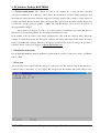
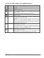
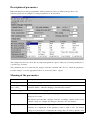
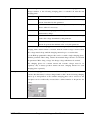
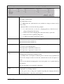
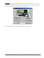
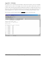
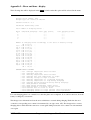
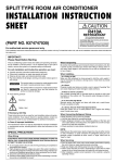
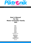
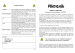
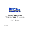
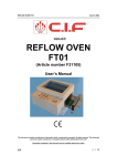
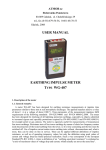
3,. 75Þ1,. Propulsion and charging devices for battery powered systems Programmable Battery Chargers USER MANUAL For chargers with firmware versions from 2.00 to 2.04 and Windows software tools Piktronik d. o. o. Ver.: 10/2007 KOP302, KOP602 and KOP1001 Battery Charger Families Microprocessor controlled, continuous duty, fully programmable, multi-stage battery charger and battery monitor Batteries have to be properly charged to achieve long term reliability. The KOP302, 602 and 1001 charger families are fully programmable accordingly to the battery manufacturer charging specifications. The parameters may be set in the factory or in the field through a unique PC interface over the charger battery output leads. Through the same interface not only the charging parameters but also a lot of other information is accessible like: charged amp-hours for the last 32 chargings, charging times, error information, voltages at which charging has been started etc. PRODUCT FEATURES: • Fully automatic operation • Charger may be left permanently attached to the batteries. It takes care about battery charging and also monitors the charging process. Completely programmable: Nickel-zinc or lead-acid (flooded, sealed and traction) batteries may be charged accordingly to battery manufacturer specifications. Up to five charging phases may be enabled to charge the battery with constant current, constant voltage or floating charge. For each of the charging phases a lot of parameters may be set as: max. current and voltage, max. charging time for that phase etc. (see example). Each charging phase (except the first one) may be conditionally executed after a defined number of Ah put into the battery or after a defined number of completed 1st charging phases. The fully automatic equalization charging phase is achievable with standard parameter set-up and may be executed after every completed charging or after pre-defined number of chargings or charged Ah's. Programmable automatic top-up cycle prevents self discharge during non-operational periods - charger starts charging after a pre-defined number of days or when the battery voltage is lower than the parameter value. The charger is fully re-programmable without opening the box. The software for the PC and a KOP-IF adapter is all what you need. • Battery monitor and Ah counter This charger is also a battery monitor at no additional cost. It collects data about how the battery has been charged: total number of charging starts and total number of connections to the battery, at what battery voltage the charging has been started – frequent deep discharges can be monitored: 16 voltage windows between 18 and 24V (24V charger) or between 36 and 48 (48V charger), total Ah charged (has the battery pack been used a lot or not) - for each charging phase Ah counting may be separately enabled (for example: Ah are not measured for the floating charge) for each charging phase Ah counting may be separately enabled (for example: Ah are not measured for the floating charge phase), how many Ah have been put into the battery during the last 32 chargings (Ah counters tell you if the battery capacity degrades or if the battery has been properly charged and also how the vehicle has been used), measurement of the charging time for the last charging (each charging phase separately) and for all chargings together. This data may be accessed trough the same PC interface as for the charger parameters. • High precision Every charger is factory calibrated - no additional user calibration is necessary. No potentiometers or other movable parts are used, therefore no vibration or corrosion problems for chargers built into the vehicles. • Temperature compensation The charger adjusts the charging voltage to compensate for the battery temperature, providing an accurate charge in any climate. A low cost external battery temperature sensor may be used to monitor battery temperature. The battery temperature monitoring and voltage compensation can be enabled for each charging phase separately and set separately (two different values) for the main charging process and for the trickle charge • Battery status LED indicators Three LED's (Error, Charging and 100%) display the executed charging phase, completed charging, float charge. Charging LED is user programmable. • Compact size, low weight, ruggedized construction and maintenance free operation PIKTRONIK Programmable chargers - User Manual 2 1. PC Software Package KOPTERM 1.1. System requirements: The software tool runs on the standard PC or notebook under operating systems from Windows ’95 to Windows ’XP. It allows the modification of battery charger parameters and the insight into all the information that the charger saves during operation. The software is always delivered together with the PC interface module. This is an adapter that is put between the battery and the charger and is connected to the PC serial port (COM1 .. COM4). The same PC interface can be used for all versions of the programmable chargers. The software is delivered on a CD or by e-mail. Updates are distributed by e-mail. The files are delivered as a self-extracting ZIP file. See the installation instructions below. In the DATA folder are always some sample parameter files (files with the extension .K61). When the software is started the first time the “File Open” function will always start inside of this folder. For many battery types Piktronik or charger distributors already have parameter files, made according to the producer’s references. Please contact your supplier or [email protected]. 1.2 Installation instructions See the INSTALL.PDF file which is distributed together with the software (on the CD or inside of a ZIP file sent by e-mail). 1.3 First start The following screen appears after the charger is connected to the PC interface and the PC interface is connected either to the battery or power supply. The energy for the PC interface and for the charger comes PIKTRONIK Programmable chargers - User Manual 3 from the battery or power supply. The charger should not be connected to the 230V voltage while it is connected to the PC interface. If the communication with the charger has failed, the following things must be verified: 1. Is the PC-interface properly connected to the battery (is the polarity OK)? 2. Is the charger properly connected to the PC-interface (look at the label on the box)? 3. For chargers with software versions lower than 2.02 the PC software has to been started first and then the PC interface connected to the charger. For chargers with software versions 2.02 and newer there are no restrictions to the sequence of software start and connections of the PC interface to the charger and battery. The software can also be used without being connected to the PC interface and the charger (to modify or edit the parameter file, for example). The software should not be started from a write protected medium like CD-ROM or write protected Flash disk. If this will be done, then the charger parameters may be transferred and inspected. However, other data read from the charger (Ah, Status) are not displayed correctly. PIKTRONIK Programmable chargers - User Manual 4 ICONS ATE THE SCREEN AND THEIR MEANING Icon Shortcut Description of the command <Ctrl-N> A new parameter file (NEW.K61) with the default parameter values will be opened Open the parameter file <Ctrl-O> <Ctrl-S> <Ctrl-P> <Ctrl-R> <Ctrl-W> PIKTRONIK Save the modified parameter file (or parameters loaded from the charger) to disk. (may be used to save status / Ah counters to the file also) Print the contents of the currently open window (Parameters, Ah counters or Status) Read the parameters from the charger. This option is available only if the charger is connected to the charger. Important: The charger always load complete data from the charger (parameters and all other information which the charger collect). If the file is saved to the disk, then all of this parameters are saved. Thus the complete information file from the charger can be sent to the supplier for the analysis (for example by e-mail). Write parameters to the charger. If many chargers have to receive the same parameter file, then this can be accomplished quickly by loading the parameter file first and then just pressing the <Ctrl-W> key combination (or clicking on this button) after the new charger is connected to the PC interface.. Selection of the font type and size. This fonts are used in the text windows (Ah counter / Status). At the moment the proportional fonts are not fully supported. We recommend the use of non-proportional fonts like "Courier New". Programmable chargers - User Manual 5 Description of parameters Piktronik chargers are fully programmable. All the parameters can be set either by the producer or by authorized personal. An example of a charger parameters is shown bellow. This example was chosen to show the most important parameter options. These are not actual parameters for a specific type of battery. The parameters may be loaded from the charger (start this command with "Tools from the charger" or use the appropriate button) or from a file ("File Ö Open"). Ö Read the parameters Meaning of the parameters Name Description Charging phases Number of charging phases (1…5) Aut. restart charging __ If charger is permanently connected to the battery and supplying mains, this days or Ub<__ parameter defines, when the charging is automatically restarted. The following parameters are valid for all charging phases Min. start volt. If the voltage, in the beginning of charging process, is lower than this value, the charger does not start. This function prevents that a charger could not overcharge a battery with a lower nominal voltage (for example 36V charger connected to the 24V battery). Voltage drop comp. With this parameter the voltage drops between the charger output and battery terminals are compensated. If the parameter value is equal to zero, the charger voltage is not increased to compensate the voltage drops. If it has a specific value PIKTRONIK Programmable chargers - User Manual 6 the charging voltage will be increased for this specific value (at charger, not at battery) if the charge current has nominal value. If the charge current is lower, the charge voltage will be increased lower. To set this parameter correctly, the maximal possible charge current must be set and up to the battery voltage, at which battery are measured to the point of end charge voltage. This point is reached when charge current starts to decline. For this parameter set the value of the voltage drop between the charger output and battery terminals. This function is very useful when charge cable is longer. When charge cable changes (length or diameter or connector) change properly this parameter. Many customers use Piktronik intelligent chargers in similar conditions (for electric vehicles for example). Optimization of parameters is recommended to get the best performance. This optimization procedure is to made only once, and store in the parameter file. This file can be loaded into other chargers working in similar conditions (using PC and PC interface). Warning: Use only calibrated instruments, especially for the battery voltage measurement. Consider that most battery types are very sensitive to overcharging. Battery type After the charger has been connected to the battery, the red LED flashes as often as this parameter has been set. Many customers use more than one battery type. To make a clear distinction, which charger has been set for which battery type, this parameter can be set differently for different battery types. Temp. compensation The value of this parameter indicates how much the charging voltage will be increased or decreased, if the battery temperature changes for 1 ºC. Please consider that battery manufacturers specify the value for one cell only and that, for example, a 12V battery has 6 cells. Here the total value (for all cells together must be entered) If this parameter is equal to zero, the temperature compensation is switched off. In this case the temperature sensor does not need to be connected. The value for trickle (maintenance) charging phase is set separately and this value also has to be zero, if the temp. sensor will not be connected. Max. voltage This parameter is used only during the active temperature compensation. It defines to which voltage the charger can increase the voltage due to temperature compensation. Batt. temperature from The battery temperature at which the charger is allowed to operate. If the measured ___ ºC to ____ ºC battery temperature is not within this range, the charger stops charging (and increases the error counter). After some time elapses the charger checks if the temperature is within this range and restarts operation (if temperature is within PIKTRONIK Programmable chargers - User Manual 7 range). Discharg. table from The charger stores information about the value of battery voltage when the charging is started. The chargers have 16 counters for 16 voltage windows (See the Appendix 2: second example – "Number of charging starts accordingly to the state of battery voltage"). If the value of the battery voltage is within one of this windows at start of the charging, then the belonging counter is incremented by one. If many counters at lower voltages have larger values then the battery has been not treated properly by the user (deeply discharged too often). It is well known that the battery voltage quickly (within seconds) recovers to a normal value (>12V for lead-acid battery with 12V nominal voltage) after the load is switched off, if the battery has not been deeply discharged. Deeply discharged, already damaged or too old batteries, may never reach normal value after the load is switched off. PIKTRONIK Programmable chargers - User Manual 8 The following parameters must be set for each charging phase separately: Max. charg. voltage The maximal output voltage of the charger. When the battery voltage reaches this value, the charging current is reduced as far as necessary. If the temperature compensation is active, the charging voltage is equal to the value of this parameter only at 25ºC. If the battery temperature is higher than 25ºC, the charging voltage is consequently lower, and increased if the temperature is lower. Min. charg. current This parameter is used only if the charging phase should be terminated, when Ib<Imin (see the description bellow) Otherwise, the parameter has no meaning. In the so called trickle charging phase (Switch phases at = No switch) this parameter represents the value of temperature compensation for this charging phase. For all other charging phases, the main parameter for the temperature compensation is active. Max. charg. current This is the maximum output current that the charger can provide. This value is reached only, when battery voltage is lower than set with the “Max. charg. voltage” parameter. Time limit (h:min) Max. duration of charging time (hours : minutes). This parameter can be used in two different ways. If this parameter is not used as time switch for the next charging phase, the charger switches off and reports an error (Time out). If this parameter is set as time switch for the next charging phase, on “Switch phases at”, then the charger just switches the phases when this time elapses. If the environment temperature is very high or the cooling fan is disabled, the charger reduces the current. The maximal time duration is then extended accordingly. PIKTRONIK Programmable chargers - User Manual 9 Switch phases at The following criteria can be selected for the termination of a charging phase. The charger switches to the following charging phase or switched off after the last charging phase. Ub >= Umax The battery voltage must reach the voltage set by this parameter. Ib < Imin The battery current must be reduced under the minimal min. charge current, determined by this parameter. Time out The determined time duration must pass over- by the charging phases, where it is necessary No switch No switch of charging phases. This parameter is used for trickle (maintenance) charge. T+Ub>=Uma It is switched over, after the time T or when the battery voltage x reaches the voltage determined by this parameter. T+Ib<Imin It is switched over, when the time T passes over or when the battery current drops under the minimal value, set by this parameter. By many chargers two charging phases must be set separately. At the beginning the charging with constant current is executed, until the certain voltage is reached, then this voltage must be kept, until the charging current drops to a certain value. For the KOP programmable chargers this can be set with a single charging phase. With the parameter "Max. charg. current" the maximal charge current is set and with the parameter "Max. charg. voltage" the charge voltage which must be reached. The charging phases for constant current and constant voltages must be set separately only, if battery producer defines the max. charging duration for each charging phase separately. Cond. phase exec after In the first charging phase there are no conditional settings. It means that the battery is always charged until ca.80%. In the following charging phases up to 20 repetitions of the available charging phase can be selected or the next phase can be conditionally executed after a defined number of Ah put into the battery. PIKTRONIK Programmable chargers - User Manual 10 The following functions can be switched on or off for every single charging phase: `L` = LED L1 - LED is switched ON L0 - LED is switched OFF L X - LED flashes slowly L - LED flashes fast (this function is not available for charger software versions 2.02 or older) Usually the LED is set as in the following example: • it is ON in the first (or first two) charging phases(s) when the most of energy is charged into the battery • flashes slowly in the charging phase where the battery is quite full, • flashes fast for the equalizing charge and • is OFF for the trickle (maintenance) charge. `A´ = Ah measurement It can be switched on or off for every charging phase. A1 = Ah measurement switched on, A0 = Ah measurement switched off `T` = temperature Compensation of battery voltage accordingly to battery temperature can be switched on or off for every charging phase. T1 = temperature compensation switched on T0 = temperature compensation switched off `R` = reload time limit counter R0 – The charging time out counter is not reloaded with the new value – the remaining time from the previous phase is used. For example in the second phase a duration period of 5 hours was programmed and only 3 hours charged. In that case the max. duration time for the next phase is 2 hours. In this way the different charging phases can be fit together or be together limited in their duration. R1 – the time limit is set separately for this phase. `F` = cooling fan speed F0- cooling fan operates at full speed or it is switched off (by low ambient control temperatures or low charge current) F1- The speed of the cooling fan is regulated regarding the charging current and ambient temperature, so the noise can be reduced. PIKTRONIK Programmable chargers - User Manual 11 PIN CODE: For using all of the functions, a pin code is necessary. Without the correct pin code some functions like: changing parameters, deletion of data stored by the charger … are disabled. A user without pin code can only inspect the parameters/data, but not change them. Please open the "Help PIKTRONIK Ö About" and then enter the pin code in the bottom field.. Programmable chargers - User Manual 12 Please, consider the following issues, when parameters setting parameters 1. The max. output power of the charger is limited. The output power = current x voltage can not go beyond the defined max. power value of the charger. The software informs via error message, if the false parameter are saved on the hard disk or transferred into the charger. 2. Please, consider the battery manufacturer charging recommendations. The life of batteries can be shorted, if the parameters are not set correctly. If batteries are used in a very wide temperature range, the temperature compensation for the most batteries is recommended or even prescribed by the battery manufacturers. 3. The battery temperature sensor should be preferably be mounted to one of the battery terminals. Attachment to the battery housing or even just measurement of ambient temperature does not give very accurate results. 4. The charging voltage is measured at the charger output. Because of the voltage drops on the cables, connectors and battery terminals, the battery voltage is always a little bit lower than it has been set. Particularly at long battery cables and large charging currents the voltage difference should not be neglected. We do not recommend to increase the charging voltages accordingly to the voltage drops, since the battery could be overcharged at the end of the charging phase when the charging current is smaller and the voltage drop also. The better choice is the correct setting of “Voltage drop” parameter. With this parameter the total voltage drop at maximal charger current is set (for example at 17A for 24V/17A charger version). For a specific application this has to be done only once and then the parameters have only to be transferred to other chargers used in the same application. Some chargers use four wires to compensate for the voltage drops on the cables. We have selected the software compensation, since it is simpler, cheaper for the end customer (less wires, simpler connectors), and also more reliable. PIKTRONIK Programmable chargers - User Manual 13 Appendix 1: Ah display The charger saves also information about the number of Ah put into the battery for the last 32 chargings separately and total counter for all chargings. If the customer has problems with the battery, then it is possible to find out how the battery has functioned during the last month (if for example the battery has been charged once each day). With additional information, how the battery has been charged (information if the single charging phases were completed) or how the battery was discharged (perhaps discharged to much). The following screen will be displayed after the [Ah Counters] option is selected in the menu. PIKTRONIK Programmable chargers - User Manual 14 Appendix 2 – Error and time – display The following data will be displayed in the [Status] window after this option will be selected in the menu. CHARGER TIME AND ERROR COUNTERS Charger serial number: 1486 Charger type: #2 = KOP601/2 24V/17A Software version: 2.03 Parameters modified by: #255 Total number of charging starts: 0 Phase 1 2 3 4 5 Completed chargings 0 0 0 0 0 Total time [hours] 0:00 0:00 0:00 0:00 0:00 Last charging [hours] 0:00 0:00 0:00 0:00 0:00 Number of charging starts accordingly to the state of battery voltage Ub <= 17,50: 0 17,50 < Ub <= 18,05: 0 18,05 < Ub <= 18,60: 0 18,60 < Ub <= 19,15: 0 19,15 < Ub <= 19,70: 0 19,70 < Ub <= 20,25: 0 20,25 < Ub <= 20,80: 0 20,80 < Ub <= 21,34: 0 21,34 < Ub <= 21,89: 0 21,89 < Ub <= 22,44: 0 22,44 < Ub <= 22,99: 0 22,99 < Ub <= 23,54: 0 23,54 < Ub <= 24,09: 0 24,09 < Ub <= 24,64: 0 24,64 < Ub <= 25,19: 0 Ub > 25,19: 0 CHARGER ERROR COUNTERS 0 0 0 0 0 0 0 0 0 0 0 0 0 0 x x x x x x x x x x x x x x #1 #2 #3 #4 #5 #6 #7 #8 #9 #10 #11 #12 #13 #14 "Charger temperature sensor failure" "Charging time-out" "Battery temperature sensor failure" "Charger heat sink temperature too high" "Battery voltage too high at start" "Battery temperature too low during charging" "Battery temperature too high during charging" "Charger disconnected from battery during charging" "Bad parameter checksum" "Bad current measurement offset value" "Bad parameter or working variable value" "Current does not start to flow" "Charging current too high (current limiting problem)" "Charging current too high (current control problem)" For each charging phase it is counted, how often the phase was completed. So it can be found out, how the battery is charged by a customer. The charger saves information about the errors which have occurred during charging. Each time the error occurs the corresponding error counter is incremented by one (up to max. 255). The charger tries to restart charging after a while and if the same error occurs again during restart, the error counter is not incremented once again. PIKTRONIK Programmable chargers - User Manual 15 Appendix 3 – Error messages No LED lights or blinks after connection to the battery and mains. Error LED is blinking 2 seconds pause / N x flashes The following things have to be checked first: 1. Battery connections and cables 2. Mains (230V) connections and cable 3. Is 230V present in the socket 4. Battery voltage (it's value must be higher than the value of parameter "", otherwise the charger is not allowed not start) N = Number of consecutive LED flashes shows the error number. See the following table for the explanation of errors. ERROR MESSAGES Light signals Description 1 Charger temperature sensor failure Internal error 2 Charging time-out Battery charging has not been completed in the (with the parameter) defined time. This happens for example in case of shorted cell or due to battery aging. 3 Battery temperature sensor failure Battery temp. sensor not connected, broken wire to the sensor, problem with the connector,... 4 Charger heat sink temperature too high Fan openings covered, ambient temperature very high, charger exposed to direct sunlight, ... 5 Battery voltage too high at start Charger has been connected to wrong battery. For example 24V charger to 36V or 48V battery. Please consider that connection of a charger to a battery with over 50% higher voltage may damage the charger. 6 Battery temperature too low during charging See below 7 Battery temperature too high during charging The battery temperature was not inside the (with parameters) defined window. After the battery cools down (or heats up) to normal temperature charging continues. 8 Charger disconnected from battery during charging Always the mains (230V) plug should be pulled out before the charger output plug. 9 Bad parameter checksum The parameters should be transferred once again to the charger. 10 Current measurement offset too high/low Internal error 11 Bad parameter or working variable value If this error does not disappear after the parameters are transferred to the charger, the charger manufacturer has to be contacted (send the parameter file downloaded from the charger). 12 Current does not start to flow Internal error 13 Charging current too high (current limiting problem) Internal error 14 Charging current too high (current control problem) Internal error PIKTRONIK Programmable chargers - User Manual 16 TECHNICAL SPECIFICATIONS Charger type KOP602 Nominal battery voltage KOP1001 24V 36V 48V 24V 36V 48V Programmable output voltage 20 – 33V 30 – 49,5V 40 – 66V 20 – 33V 30 – 49,5V 40 – 66V Programmable output current 0,3 – 17A 0,2 – 12A 0,15 – 9A 0,60 – 34A 0,40 – 24A 0,30 – 18A Input voltage 230V ±10% 50-60Hz 230V ±10% 50-60Hz Input power 600W 1200W Ambient temperature range -25 to 35°C (gradual power reduction at higher ambient temperatures) Operating humidity 15 to 95% RH (non condensing) Weight (including 2 m cable) 2,0 kg 3,6 kg Dimensions (l x w x h) in mm 240 x 108 x 82 240 x 215 x 82 Env. protection and approvals IP21 / EN60 335-1 / EN60 335-2-29 Options: • drive controller disable during charging (relay with 10A contact rating) for application in electrical vehicles and • serial link to electrical vehicle display. Protection features: • overload and short-circuit protection, • reverse polarity protection, • gradual power reduction at elevated ambient temperatures, • non-sparking feature for safe battery connection, • time-out programmable separately for each of the charging phases, • battery temperature monitoring (with optional temperature sensor) for battery protection and charging voltage compensation, • self check functions (at start and during operation). Piktronik d. o. o. Cesta k Tamu 17 SI – 2000 Maribor Slovenia Phone: Fax: Web Site: Information: Support: PIKTRONIK +386 2 4602 250 +386 2 4602 255 http://www.pikronik.com [email protected] [email protected] Programmable chargers - User Manual 17