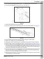
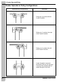
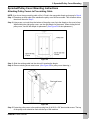
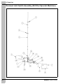
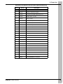
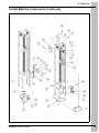
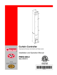
1
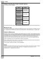
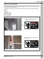
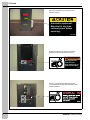
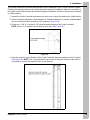
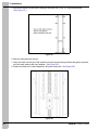
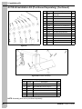
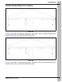
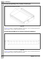
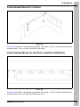
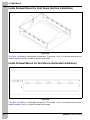
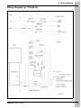
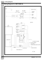
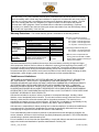
Curtain Controller
Sprocket and Chain Drive
Featuring the Header Sprocket System
Operation and Installation Manual
PNEG-881
Date: 03-09-09
PNEG-881
This equipment shall be installed in accordance with the current installation codes and
applicable regulations which should be carefully followed in all cases. Authorities having
jurisdiction should be consulted before installation occurs.
2
PNEG-881 Curtain Controller
Table of Contents
Contents
Chapter 1 Safety.................................................................................................................................................. 4
Safety Guidelines ............................................................................................................................... 4
General Safety Statement ................................................................................................................. 5
Chapter 2 Decals................................................................................................................................................. 7
Chapter 3 Installation ......................................................................................................................................... 9
Chapter 4 Header Sprocket/Pulley .................................................................................................................. 12
Header Sprocket or Pulley Configurations ....................................................................................... 12
Chapter 5 Sprocket/Pulley Cover Mounting ................................................................................................... 13
Sprocket/Pulley Cover Mounting Instructions .................................................................................. 13
Chapter 6 Maintenance..................................................................................................................................... 14
Chapter 7 Troubleshooting Guide ................................................................................................................... 15
Chapter 8 Parts List .......................................................................................................................................... 17
Enclosed Limit Switch Assembly (SPRKT2430 and SPRKT2460 Only) ......................................... 17
Enclosed Limit Switch Assembly (All Other Sprocket Machines) .................................................... 18
Curtain Machine Components ......................................................................................................... 20
Chapter 9 Installation Kit.................................................................................................................................. 24
AC180-A Installation Kit (Purchased Separately) ............................................................................ 24
AC180-B Installation Kit (Purchased Separately) ............................................................................ 25
Chapter 10 Wall Mount ..................................................................................................................................... 27
Outside Endwall Mount for Curtains ..............................................................................................
Outside Sidewall Mount for Curtains (Vertical Installation) ............................................................
Inside Endwall Mount for Curtains .................................................................................................
Inside Sidewall Mount for Vent Doors (Vertical Installation) ..........................................................
Inside Endwall Mount for Vent Doors (Vertical Installation) ...........................................................
Inside Sidewall Mount for Vent Doors (Horizontal Installation) ......................................................
27
28
29
29
30
30
Chapter 11 Wiring Diagrams............................................................................................................................ 31
Wiring Diagram for 110V 60 Hz ..................................................................................................... 31
Wiring Diagram for 220V 50/60 Hz ................................................................................................ 32
Chapter 12 Warranty......................................................................................................................................... 33
PNEG-881 Curtain Controller
3
1. Safety
Safety Guidelines
This manual contains information that is important for you, the owner/operator, to know and understand.
This information relates to protecting personal safety and preventing equipment problems. It is the
responsibility of the owner/operator to inform anyone operating or working in the area of this equipment
of these safety guidelines. To help you recognize this information, we use the symbols that are defined
below. Please read the manual and pay attention to these sections. Failure to read this manual and its
safety instructions is a misuse of the equipment and may lead to serious injury or death.
This is the safety alert symbol. It is used to alert you to
potential personal injury hazards. Obey all safety
messages that follow this symbol to avoid possible
injury or death.
DANGER indicates an imminently hazardous situation
which, if not avoided, will result in death or serious injury.
WARNING indicates a potentially hazardous situation
which, if not avoided, could result in death or serious injury.
CAUTION indicates a potentially hazardous situation which,
if not avoided, may result in minor or moderate injury.
CAUTION used without the safety alert symbol indicates a
potentially hazardous situation which, if not avoided, may
result in property damage.
NOTE indicates information about the equipment that you
should pay special attention.
4
PNEG-881 Curtain Controller
1. Safety
General Safety Statement
Our foremost concern is your safety and the safety of others associated with grain handling equipment.
This manual is to help you understand safe operating procedures and some problems which may be
encountered by the operator and other personnel.
As owner and/or operator, you are responsible to know what requirements, hazards and precautions
exist and inform all personnel associated with the equipment or in the area. Safety precautions may be
required from the personnel. Avoid any alterations to the equipment, which may produce a very
dangerous situation, where SERIOUS INJURY or DEATH may occur.
Electrical Safety
An adequate and safe power supply to the Curtain Controller unit is essential for safety. A competent
and qualified electrician must undertake all electrical wiring. All wiring is to be installed according to the
National Standards and Regulations relevant to your Country and Region.
Electrical safety devices, emergency stop and main isolators are provided with the Curtain Controller
System and are essential for safety. This should be installed as indicated in the enclosed installation
instructions and in accordance with the relevant codes and directives.
User’s Manual
This manual contains information and instructions essential to the safe installation and use of the
Curtain Controller System. Read this manual thoroughly before attempting any installation or use
of the Curtain Controller System. Keep this manual with the Curtain Controller System or in a location
where it can be readily accessed. Failure to read this manual and its safety instructions is a misuse
of the equipment.
Correct Uses of Your Curtain Controller
The Curtain Controller System is designed solely for the purpose of controlling vent doors in livestock
(swine and chicken) houses. Use of the system in any other way is a misuse of the system and may
endanger safety and health.
Only genuine AP/Cumberland parts are to be used in the installation and use of the Curtain Controller
System. Use of other non-genuine parts is a misuse of the system and may lead to dangerous situations
imperilling the safety and health of you and others.
Controls
The Curtain Controller is designed for use with manual or automatic temperature control. GSI recommends
the use of genuine GSI controls. Use of any controllers that do not meet this specification can pose a risk
to health and safety and will lead to malfunction and failure of the Curtain Controller.
This machine is not designed for use in atmospheres where there is a risk of explosion. Use of the Curtain
Controller System in such an environment is prohibited. If in doubt, contact your dealer or GSI.
Safety Guards
The Curtain Controller System contains many moving and electrical parts, which will cause serious injury
or death if touched. Guards are placed on the machine for your protection. Operating the machine
at any time with guards removed or incorrectly fitted is a serious misuse of the machine and
endangers safety.
PNEG-881 Curtain Controller
5
1. Safety
Safety in Handling the Curtain Controller System
The Curtain Controller weights:
Model #
Weight
SPRKT2415
SPRKT2430
104 lbs/47 kg
SPRKT2460
SPRKT3615
SPRKT3630
119 lbs/54 kg
SPRKT3660
SPRKT4815
SPRKT4830
135 lbs/61 kg
SPRKT4860
SPRKT6015
SPRKT6030
151 lbs/69 kg
SPRKT6060
All precautions should be taken when lifting and/or moving the unit, to prevent the risk of physical injury.
Maximum Load
The Curtain Controllers with 15 RPM and 30 RPM gear motors can lift a maximum of 4000 lbs/1814 kg
at a 1:2 pulley ratio. 60 RPM Gear motors can lift a maximum of 1000 lbs/453 kg at a 1:2 pulley ratio.
Safety in Maintenance
While the Curtain Controller is designed to keep maintenance to a minimum, some maintenance will be
necessary in the course of the life of the machine. Do not attempt any repairs on the machine unless you
are competent to do so. Remember that the Curtain Controller may operate under automatic control and
start without warning. Never attempt any work on the Curtain Controller without first isolating the
machine from the main power and locking the isolator so that only you can turn the power back ON.
Follow all guidelines given in the maintenance section of this manual.
Before restarting the Curtain Controller, ensure that all electrical enclosures are locked closed and all
guards and other safety measures are correctly fitted.
If in any doubt, contact your dealer or GSI for assistance.
Noise
Tests on this machine indicate noise levels at a position one (1) meter from the drive unit, and 1.6 meters
above the ground do not exceed 70 dBa, continuous “A” weighted sound pressure or 63 Pa,
instantaneous “C” weighted sound pressure.
6
PNEG-881 Curtain Controller
2. Decals
Safety Decals and Warnings
The following pages show you exactly where the safety signs and warnings (decals) should be placed
on your Curtain Controller. If a decal is missing, damaged or unreadable, please contact your dealer or
the GSI group, for a free replacement.
For guidance or assistance on any issues relating to the safe use of the Curtain Controller System,
Contact:
GSI Group
1004 E. Illinois St.
Assumption, IL. 62510
Phone: 217-226-4421
Fax: 217-226-4420
Decal-889 is located above the electrical box on
the outside of the Curtain Controller.
DC-889 is located on the electrical unit within the
Curtain Controller.
PNEG-881 Curtain Controller
7
2. Decals
DC-1516 is located on the front cover of the
Curtain Controller.
Automatic equipment.
May start at any time.
Lockout power before
servicing.
DC-1516
DC-856 is located on the sides of the Curtain
Controller underneath the sprocket covers.
WARNING
Moving parts can
crush and cut.
Keep hands clear of
sprocket and chain.
DC-856
DC-1517 is located underneath the sprocket
covers above the warning decal (DC-856) on the
Curtain Controller.
8
PNEG-881 Curtain Controller
3. Installation
This manual outlines the recommended sequence for the installation of the Curtain Controller System.
Following the sequence will prove the safest and easiest method of installation. Above all, connection of
the system to the electrical mains should be final stage of installation. Failure to observe this could lead
to a fatal accident.
1. Unpack the Curtain Controller and remove the front cover. Inspect the machine for visible defects.
2. Select mounting configuration. (See examples of: Outside sidewall one (1) curtain, outside endwall
two (2) curtains and inside endwall two (2) curtains on Page 27-30.)
3. Screw one (1) 3/8" x 3" lag bolt 6-1/2" below the desired height of the Curtain Controller.
NOTE: Leave 1-1/2" between the bolt head and the wall. (See Figure 3A.)
Figure 3A
4. Using the “keyhole” slot in the back of the Curtain Controller, hang the machine on the 3" lag bolt.
(See Figure 3B.) NOTE: The 3" lag bolt should only be used to hang the machine to the wall. Do
not attempt to operate the machine until it is fully secured.
Figure 3B
PNEG-881 Curtain Controller
9
3. Installation
5. Secure the machine to the wall by using the minimum six (6) 3/8" x 2" lag bolts provided.
(See Figure 3C.)
Figure 3C
6. Remove pulley/sprocket covers.
7. Insert the chain into the top of the machine onto the sprocket and pull down through the machine
until the chain reaches the chain adapter. (See Figure 3D.)
8. Fasten the chain to the chain adapter by using the master link. (See Figure 3D.)
Figure 3D
10
PNEG-881 Curtain Controller
3. Installation
9. Cut an opening in the pulley/sprocket cover 3/4'' x 1/2'' where the chain will exit the cover.
10. Insert the chain through the pulley/sprocket cover. (See Figure 3E.)
Figure 3E
11. Replace the pulley/sprocket cover to the machine.
12. Attach chain adapter to the end of the chain and the swivel to the chain adapter. (See Figure 3F.)
Figure 3F
13. Loop the cable through the swivel and fasten together with three (3) cable clamps.
14. Repeat Step 7 through Step 13 for the opposite side.
15. Install pulleys, brackets, hand winches etc., according to the appropriate mounting configuration.
16. Wire the Curtain Controller to the appropriate control. (See Wiring Diagrams on Pages 31 and 32.)
17. Close the curtains/vent doors fully using the manual mode of the controls. Set the lower limit using
the lower limit adjustment collar. NOTE: Be sure to tighten the limit switch adjustment collar. Failure
to do so can cause damage to the machine and barn. Take up excess slack in the cable using the
manual winch while paying close attention not to overtighten.
18. Open the curtains/vent doors to the desired opening using the manual mode of the controls. Set the
upper limit switch adjustment collar. NOTE: Be sure to tighten the limit switch adjustment collar.
Failure to do so can cause damage to the machine and barn.
19. Attach the door to the machine. This will protect the integrity of the machine and ensure the safety
of those working on or near the machine.
PNEG-881 Curtain Controller
11
4. Header Sprocket/Pulley
Header Sprocket or Pulley Configurations
Sprocket/Pulley Configuration(s)
Used when
Pulling two (2) curtains with the
Curtain Controller.
Pulling one (1) curtain to the right
of the Curtain Controller.
Pulling one (1) curtain to the left
of the Curtain Controller.
Curtain Controller is mounted
horizontally. Remove the cap plugs
in the top of the machine and run
cables through the top holes.
12
PNEG-881 Curtain Controller
5. Sprocket/Pulley Cover Mounting
Sprocket/Pulley Cover Mounting Instructions
Attaching Pulley Covers to Pre-existing Cable
NOTE: If you do not have pre-existing cable, drill a 1/4" hole in the appropriate dimple and proceed to Step 4.
Step 1: Determine on which side of the machine the pulley cover will be mounted. This will affect where
the slot will be cut in Step 2.
Step 2: Using a saw, cut a slot from the bottom of the pulley cover lip to the dimple on the cover’s face.
When slotting the right pulley cover, use the right dimple for placement. When slotting the left
pulley cover, use the left dimple for placement. (See Figure 5A for slot placement.)
Figure 5A
Step 3: Slide the existing cable into the slot until it reaches the dimple.
Step 4: Remove existing sheet metal screw. (See Figure 5B for pulley cover fastening.)
Figure 5B
Step 5: Fasten the pulley cover to the machine using four (4) #10-16 x 5/8" sheet metal screws. The top
of the pulley cover should be flush with the top of the machine.
PNEG-881 Curtain Controller
13
6. Maintenance
Safety in Maintenance and Repairs
Before starting any repairs or maintenance on you Curtain Controller System or control units, observe
the following safety steps:
1. Isolate the system from the electricity supply by switching OFF the power isolator and lock it in the
OFF position.
2. Keep the key in the possession.
3. Do not reconnect the power supply until all work is completed and all guards are correctly refitted.
It is recommended that the end user practices a monthly inspection of the Curtain Controller and all items
used in conjunction (cables, pulleys, brackets, hand winches etc.,) with the machine.
1. Inspect the drive screw. Lubricate liberally with a lithium grease of an NLGI No. 2 consistency
(extreme pressure properties).
2. Inspect and tighten the locking collars on the adjustment rod to ensure activation of limit switches.
3. Inspect cable, pulleys, brackets, hand winches etc., for alignment and premature wear. Realign
and/or replace as needed.
4. Inspect bearings checking for smooth rotation and listening for squeaks.
5. Inspect set screws in couplers and in pillow block bearing.
6. Manually run machine in both directions to ensure positive shut off and unrestricted cable movement.
7. Inspect drive screw for debris in the threads. Debris in threads may cause premature failure of
drive block.
8. Inspect the thrust bearing. Lubricate as needed.
14
PNEG-881 Curtain Controller
7. Troubleshooting Guide
Problem
1. Will not run in manual mode.
Possible Cause
1. Control not in manual mode.
2. Toggle switch failure.
Corrective Action
1. Move switch to manual setting. Check
for loose wire connection.
2. Replace toggle switch.
1. Machine operates in opposite
direction in response to
temperature change.
1. Control wired incorrectly.
1. Re-wire to wiring schematic instruction.
1. Runs in both directions (automatic
mode), but only one direction
(manual mode).
1. Control failure.
1. Check for loose wire connection.
2. No power (circuit breaker or fuse).
2. Replace Control.
2. Will not run in either direction
(manual or automatic modes).
3. Tripping may indicate machine
overload or electrical wire short.
Repair or replace before
reenergizing circuit.
3. Check main panel circuit breaker
or fuse.
4. Motor failure.
5. Control failure.
6. Primary switch failure.
4. Check control circuit breaker
and/or fuse.
5. Motor designed with internal thermal
protection. Before replacing, allow
motor to cool down and reset. May
indicate machine overload. Contact
factory for machine restrictions.
6. Check to see if secondary switch is
not depressed.
7. Replace primary switch.
1. Will not run in automatic but does
operate in manual.
1. Control not in automatic mode.
1. Move switch to automatic setting.
2. Control failure
2. Replace control.
1. Runs in one direction only, both
automatic and manual.
1. Broken or loose wire.
1. Repair broken or loose wire.
2. Limit switch catching on adjustment
rod mechanism.
2. Free switch and adjust as needed.
3. Limit switch failure.
3. Replace switch.
4. Control failure.
4. Replace Control.
PNEG-881 Curtain Controller
15
NOTES
16
PNEG-881 Curtain Controller
8. Parts List
Enclosed Limit Switch Assembly (SPRKT2430 and
SPRKT2460 Only)
Ref #
PNEG-881 Curtain Controller
Part #
Description
1
52-0337
Limit Switch Rod Retainer
2
50-0159
Adjustment Collar
3
S-2126
1/4" SAE Washer
4
52-0170
Spring
5
52-0336
Limit Switch Actuator
6
S-7974
Curtain Controller Limit Switch
7
52-0322
Gasket, Flat 4" x 6" Box
8
52-0318
Lid 4" x 6" Flat
9
52-0335
Limit Switch Mounting Plate
10
52-0340
Limit Switch Box Drilled
11
52-0338
Limit Switch Box Mounting Plate
12
50-0144
24" Travel Adjustment Rod
13
52-0339
Limit Switch Actuator
14
52-0341
24" Limit Switch Assembly Vent Mach
17
8. Parts List
Enclosed Limit Switch Assembly (All Other Sprocket Machines)
18
PNEG-881 Curtain Controller
8. Parts List
Enclosed Limit Switch Parts (All Other Sprocket Machines)
Ref #
Part #
Description
1
52-0323
Limit Switch Box
2
52-0319
Bracket, Limit Switch Support
3
52-0320
Channel, Electrical Box Mounting 4" x 6"
4
52-0322
Gasket, Flat 4" x 6" Box
5
52-0318
Lid 4" x 6" Flat
6
50-0144
24" Travel Adjustment Rod
6
50-0145
36" Travel Adjustment Rod
6
50-0146
48" Travel Adjustment Rod
6
50-0147
60" Travel Adjustment Rod
7
52-0321
Adjustment Rod Retainer 4" x 6"
8
50-0159
Adjustment Collar
9
52-0171
Angle, Limit Actuator
10
FH-1310
Cord Connector
11
FH-1309
Lock Nut 1/2" #401 ARL.
12
52-0331
Water Shield
13
S-2126
1/4" SAE Washer
14
S-7967
Set Screw #10-32 x 1-1/4"
15
S-280
Screw, SDS #10-16 x 5/8" HWH ZN
16
52-0170
Spring, Adjustment Rod Extension
17
S-7377
Screw, MS #10-24 x 1" RHP ZN Grade 2
18
S-849
Hex Nut #10-24 ZN Grade 2
19
S-7974
Straight Actuator Micro Switch
20
S-8810
Screw, SMSAB #4 x 1" PHP ZN
PNEG-881 Curtain Controller
19
8. Parts List
Curtain Machine Components
20
PNEG-881 Curtain Controller
8. Parts List
Curtain Machine Components (Continued)
PNEG-881 Curtain Controller
21
8. Parts List
Curtain Machine Components (Continued)
22
PNEG-881 Curtain Controller
8. Parts List
Curtain Machine Components Parts List
Ref #
Part #
Description
Qty
1
52-0004
Base Plate 3'
1
2
52-0001
Frame Side Left 3'
1
3
52-0002
Frame Side Right 3'
1
4
52-0006
Pulley Support Plate
1
5
52-0188M
Sprocket/Pulley Shoulder Bolt
2
6
52-0010
Pulley Spacer
2
7
52-0298
Bearing, #50 Sprocket w/ Needle
2
8
S-8072
Bolt HHCS 5/16"-18 x 3/4" ZN
9
9
S-1147
Split Lock Washer 5/16" ZN
12
10
S-396
Nut 5/16"-18
15
11
52-0007
Angle (Drive Block) 3
2
12
50-0043
Insert, Threaded 3/8"-16
2
13
S-8739
Flat Washer 3/8" x 1-1/2" x 1/4" TH
2
14
52-0348
Bearing, 1" Pillow Block w/ Set Screws
1
15
50-0056
Drive Screw, 36" Travel
1
16
52-0330
Coupler, Drive One Piece Machined
1
17
52-0012
Coupler, Spider Hytrel 7/8" F/LO95 Love Joy
1
18
52-0051
Motor Assembly 30 RPM CC
1
19
52-0172
Limit Switch Assembly 3'
1
20
52-0276
Drive Block Assembly w/ Nylon Insert
1
21
AC52-0174
Bearing Kit w/ Bearing Cover Nut
1
22
52-0195
4" x 6" Electrical Box Assembly CC MAC
1
23
52-0021
Top Cover
1
24
52-0044
Caplug, BPF-1
2
25
53-0007
Pulley Cover
2
26
52-0022
End Cap
1
27
S-280
Screw SDS #10-16 x 5/8" HWH ZN
22
28
S-7927
Bolt Flange 3/8"-16 x 1" ZN Grade 8
18
29
S-248
Flat Washer 3/8" 7/16" I.D. x 1" O.D. YDP
10
30
S-1146
Bolt HHCS 5/16"-18 x 1" ZN Grade 2
3
31
52-0036
Latch Out Switch Bracket
1
32
S-1054
Lock Washer, 3/8"
14
33
S-456
Hex Nut 3/8"-16 YDP Grade 5
14
34
S-8979
Insert, Threaded 1/4"-20 Steel/Zinc-Yellow Dichromate
2
35
S-2086
Bolt HHCS 3/8"-16 x 1-1/2" ZN Grade 8
2
36
FH-1310
Cord Connector, Heyco
2
37
FH-1309
Lock Nut 1/2" #401 ARL.
2
38
1573
Regular Limit Switch
1
1
39
1568
Whisker Switch/Limit Switch
40
S-7148
Weld Nut 6-32 TAP 1" Centers
1
41
S-8780
Screw, MS #6-32 x 2-1/2"
2
2
42
S-8940
Wing Nut #6-32 ZN Grade 2
43
52-0025
Front Cover 3' AVS Curtain Control
1
44
DC-889
Decal, Danger High Voltage
1
45
DC-1516
Decal: Caution Automatic Equipment
1
46
DC-1517
Decal: Danger, Sprocket/Chain
2
47
DC-818
Decal, New CC Front Panel
1
48
DC-1345
Decal: Danger, Sprocket/Chain
1
49
DC-1538
Decal, CC-Grease Zerk Locations
1
50
DC-789
Decal, Orange Adjustment Line
2
51
52-0211
CC Hardware Package
1
52
S-9319
Clevis Pin 1/4" x 2"
1
53
S-6626
Cotter Pin 3/32" x 1/2" ZN Grade 2
1
54
52-0301M
CC #50 Sprocket Hardware Kit 36" Machine
1
PNEG-881 Curtain Controller
23
9. Installation Kit
AC180-A Installation Kit (Purchased Separately)
AC1820 Bracket - Outside Corner Assembly
Ref #
Part #
Description
Qty
1
BAC1820 Corner Bracket Assembly
1
2
S-9046
Screw, Lag 3/8" x 3" HH ZN Grade 2
4
3
S-248
Flat Washer 3/8" 7/16" I.D. x
1" O.D. YDP
4
4
S-6554
Tie, Wire 8" Plastic
1
Figure 9A AC1820 Assembly
AC1821 Bracket - 3" x 3" x 9" 2 Pulley Assembly
Ref #
Part #
Description
Qty
1
1821
Bracket - 3" x 3" x 9" for 2 Pulleys
1
2
S-9206
Bolt, U-Bolt 3/8"-16 x 2" Long x 1"
2
3
S-456
Hex Nut 3/8"-16 YDP Grade 5
4
4
1902AA
Pulley, 3-1/2" O.D. Cast Iron WI
2
Figure 9B AC1821 Assembly
AC1822 Bracket - 3" x 3" x 3" 1 Pulley Assembly
Ref #
Part #
Description
Qty
1
1822
Bracket - 3" x 3" x 3" for 1 Pulley
1
2
S-9206
Bolt, U-Bolt 3/8"-16 x 2" Long x 1"
1
3
S-456
Hex Nut 3/8"-16 YDP Grade 5
2
4
1902AA
Pulley, 3-1/2" O.D. Cast Iron WI
1
Figure 9C AC1822 Assembly
24
PNEG-881 Curtain Controller
9. Installation Kit
AC180-A Installation Kit (Purchased Separately) (Continued)
Ref #
Part #
Description
Qty
1
S-248
Flat Washer 3/8" 7/16" I.D. x
1" O.D. YDP
50
2
S-456
Hex Nut 3/8"-16 YDP Grade 5
20
3
S-7522
Bolt HHCS 3/8"-16 x 2" ZN Grade 2
5
4
S-7249
Bolt HHCS 3/8"-16 x 3" ZN Grade 5
6
5
S-7373
Bolt HHCS 3/8"-16 x 5" ZN Grade 2
2
6
S-7248
Bolt HHCS 3/8"-16 x 6" ZN Grade 2
2
7
S-8395
Bolt HHCS 3/8"-16 x 7" ZN Grade 2
4
8
8195
Rod Threaded 3/8"-16 x 12" Grade 2
4
9
S-8762
3/16" Cable Clamp, ZN Plated
11
10
1926
Hook Grab 1/4" Chain
2
11
1780
Handy Box Cover-Galvanized
1
12
1781
Duplex Receptacle-115V w/ Ground
1
13
1785
Handy Box-Surface Mount Nail On
1
14
1782
Connector, 3/8" Romex, 1/2" Thread
1
Figure 9D
NOTE: Assembly parts can be purchased separately.
AC180-B Installation Kit (Purchased Separately)
AC1821 Bracket - 3" x 3" x 9" 2 Pulley Assembly
Ref #
Part #
Description
Qty
1
1821
Bracket - 3" x 3" x 9" for 2 Pulleys
1
2
S-9206
Bolt, U-Bolt 3/8"-16 x 2" Long x 1"
2
3
S-456
Hex Nut 3/8"-16 YDP Grade 5
4
4
1902AA
Pulley, 3-1/2" O.D. Cast Iron WI
2
Figure 9E AC1821 Assembly
PNEG-881 Curtain Controller
25
9. Installation Kit
AC180-B Installation Kit (Purchased Separately) (Continued)
Ref #
Part #
Description
Qty
1
S-248
Flat Washer 3/8" 7/16" I.D. x
1" O.D. YDP
2
S-456
Hex Nut 3/8"-16 YDP Grade 5
21
3
S-7522
Bolt HHCS 3/8"-16 x 2" ZN Grade 2
3
4
S-7249
Bolt HHCS 3/8"-16 x 3" ZN Grade 5
3
5
S-7373
Bolt HHCS 3/8"-16 x 5" ZN Grade 2
2
6
S-7248
Bolt HHCS 3/8"-16 x 6" ZN Grade 2
2
7
S-8395
Bolt HHCS 3/8"-16 x 7" ZN Grade 2
2
8
8195
Rod Threaded 3/8"-16 x 12" Grade 2
4
9
S-8762
3/16" Cable Clamp, ZN Plated
8
10
1926
Hook Grab 1/4" Chain
2
11
1780
Handy Box Cover-Galvanized
1
12
1781
Duplex Receptacle-115V w/ Ground
1
50
13
1785
Handy Box-Surface Mount Nail On
1
14
1782
Connector, 3/8" Romex, 1/2" Thread
1
Figure 9F
Figure 9G AC1820C Assembly
AC1820C Heavy Duty Outside Corner Bracket
Ref #
Part #
Description
Qty
1
1820C1
Bracket - Outside Corner
1
2
S-9206
Bolt, U-Bolt 3/8"-16 x 2" Long x 1"
1
3
S-248
Flat Washer 3/8" 7/16" I.D. x 1" O.D. YDP
4
4
S-456
Hex Nut 3/8"-16 YDP Grade 5
4
5
1902AA
Pulley, 3-1/2" O.D. Cast Iron WI
1
6
S-9046
Screw, Lag 3/8" x 3" HH ZN Grade 2
6
NOTE: Assembly parts can be purchased separately.
26
PNEG-881 Curtain Controller
10. Wall Mount
Outside Endwall Mount for Curtains
Figure 10A
The Figure 10A shows 1:2 chain/cable configuration. This means: 1 foot (1') of chain movement at the
machine equals 2 feet (2') of cable movement at the curtain.
Figure 10B
The Figure 10B shows 1:1 chain/cable configuration. This means: 1 foot (1') of chain movement at the
machine equals 1 foot (1') of cable movement at the curtain.
PNEG-881 Curtain Controller
27
10. Wall Mount
Outside Endwall Mount for Curtains (Continued)
Illustration shows table configuration of the sidewall.
Figure 10C
The Figure 10C shows 1:1 chain/cable configuration. This means: 1 foot (1') of chain movement at the
machine equals 1 foot (1') of cable movement at the curtain.
Outside Sidewall Mount for Curtains (Vertical Installation)
Figure 10D
The Figure 10D shows 1:2 chain/cable configuration. This means: 1 foot (1') of chain movement at the
machine equals 2 feet (2') of cable movement at the curtain.
28
PNEG-881 Curtain Controller
10. Wall Mount
Inside Endwall Mount for Curtains
Figure 10E
The Figure 10E shows 1:1 chain/cable configuration. This means: 1 foot (1') of chain movement at the
machine equals 1 foot (1') of cable movement at the curtain.
Inside Sidewall Mount for Vent Doors (Vertical Installation)
Figure 10F
The Figure 10F shows 1:1 chain/cable configuration. This means: 1 foot (1') of chain movement at the
machine equals 1 foot (1') of cable movement at the doors.
PNEG-881 Curtain Controller
29
10. Wall Mount
Inside Endwall Mount for Vent Doors (Vertical Installation)
Figure 10G
The Figure 10G shows 1:2 chain/cable configuration. This means: 1 foot (1') of chain movement at the
machine equals 2 feet (2') of cable movement at the doors.
Inside Sidewall Mount for Vent Doors (Horizontal Installation)
Figure 10H
The Figure 10H shows 1:1 chain/cable configuration. This means: 1 foot (1') of chain movement at the
machine equals 1 foot (1') of cable movement at the doors.
30
PNEG-881 Curtain Controller
11. Wiring Diagrams
Wiring Diagram for 110V 60 Hz
PNEG-881 Curtain Controller
31
11. Wiring Diagrams
Wiring Diagram for 220V 50/60 Hz
32
PNEG-881 Curtain Controller
Limited Warranty
The GSI Group, LLC. (“GSI”) warrants products which it manufactures to be free of defects in materials
and workmanship under normal usage and conditions for a period of 12 months after sale to the original
end-user or if a foreign sale, 14 months from arrival at port of discharge, whichever is earlier. The enduser’s sole remedy (and GSI’s only obligation) is to repair or replace, at GSI’s option and expense,
products that in GSI’s judgment, contain a material defect in materials or workmanship. Expenses
incurred by or on behalf of the end-user without prior written authorization from the GSI Warranty Group
shall be the sole responsibility of the end-user.
Warranty Extensions: The Limited Warranty period is extended for the following products:
AP Fans and
Flooring
Cumberland
Feeding/Watering
Systems
Grain Systems
Grain Systems
Farm Fans
Zimmerman
Product
Performer Series Direct Drive
Fan Motor
All Fiberglass Housings
All Fiberglass Propellers
Feeder System Pan Assemblies
Feed Tubes (1.75" & 2.00")
Centerless Augers
Watering Nipples
Grain Bin Structural Design
Portable & Tower Dryers
Portable & Tower Dryer Frames
and Internal Infrastructure †
Warranty Period
3 Years
Lifetime
Lifetime
5 Years **
10 Years *
10 Years *
10 Years *
5 Years
2 Years
5 Years
* Warranty prorated from list price:
0 to 3 years – no cost to end-user
3 to 5 years – end-user pays 25%
5 to 7 years – end-user pays 50%
7 to 10 years – end user pays 75%
** Warranty prorated from list price:
0 to 3 years – no cost to end-user
3 to 5 years – end-user pays 50%
† Motors, burner components and
moving parts not included. Portable
Dryer screens included. Tower Dryer
screens not included.
GSI further warrants that the portable and tower dryer frame and basket, excluding all auger and auger
drive components, shall be free from defects in materials for a period of time beginning on the twelfth (12th)
month from the date of purchase and continuing until the sixtieth (60th) month from the date of purchase
(extended warranty period). During the extended warranty period, GSI will replace the frame or basket
components that prove to be defective under normal conditions of use without charge, excluding the labor,
transportation, and/or shipping costs incurred in the performance of this extended warranty.
Conditions and Limitations:
THERE ARE NO WARRANTIES THAT EXTEND BEYOND THE LIMITED WARRANTY DESCRIPTION
SET FORTH ABOVE. SPECIFICALLY, GSI MAKES NO FURTHER WARRANTY OF ANY KIND,
EXPRESS OR IMPLIED, INCLUDING, WITHOUT LIMITATION, WARRANTIES OF MERCHANTABILITY
OR FITNESS FOR A PARTICULAR PURPOSE OR USE IN CONNECTION WITH: (i) PRODUCT
MANUFACTURED OR SOLD BY GSI OR (ii) ANY ADVICE, INSTRUCTION, RECOMMENDATION OR
SUGGESTION PROVIDED BY AN AGENT, REPRESENTATIVE OR EMPLOYEE OF GSI REGARDING
OR RELATED TO THE CONFIGURATION, INSTALLATION, LAYOUT, SUITABILITY FOR A PARTICULAR
PURPOSE, OR DESIGN OF SUCH PRODUCTS.
GSI shall not be liable for any direct, indirect, incidental or consequential damages, including, without
limitation, loss of anticipated profits or benefits. The sole and exclusive remedy is set forth in the Limited
Warranty, which shall not exceed the amount paid for the product purchased. This warranty is not
transferable and applies only to the original end-user. GSI shall have no obligation or responsibility for any
representations or warranties made by or on behalf of any dealer, agent or distributor.
GSI assumes no responsibility for claims resulting from construction defects or unauthorized modifications
to products which it manufactured. Modifications to products not specifically delineated in the manual
accompanying the equipment at initial sale will void the Limited Warranty.
This Limited Warranty shall not extend to products or parts which have been damaged by negligent use,
misuse, alteration, accident or which have been improperly/inadequately maintained. This Limited Warranty
extends solely to products manufactured by GSI.
Prior to installation, the end-user has the responsibility to comply with federal, state and local codes which
apply to the location and installation of products manufactured or sold by GSI.
9101239_1_CR_rev7.DOC
(revised July 2009)
This equipment shall be installed in accordance with
the current installation codes and applicable
regulations which should be carefully followed in all
cases. Authorities having jurisdiction should be
consulted before installations are made.
1004 E. Illinois St.
Assumption, IL 62510-0020
Phone: 1-217-226-4421
Fax: 1-217-226-4420
www.gsiag.com
Copyright © 2009 by
Printed in the USA
Group