1
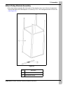
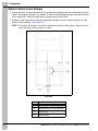
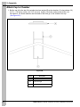
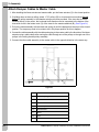
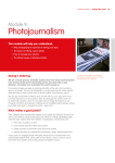
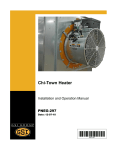
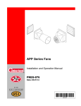
36" Natural Ventilation Chimney
Installation Manual
PNEG-1932
Date: 03-26-15
PNEG-1932
All information, illustrations, photos and specifications in this manual are based on the latest
information available at the time of publication. The right is reserved to make changes at any
time without notice.
2
PNEG-1932 36" Natural Ventilation Chimney Installation Instructions
Table of Contents
Contents
Chapter 1 Safety .....................................................................................................................................................4
Cautionary Symbols Definitions .............................................................................................................4
General Safety Statement ......................................................................................................................5
User’s Manual ........................................................................................................................................5
Correct Use of the Natural Ventilation Chimney ....................................................................................5
Safety in Handling the Natural Ventilation Chimney ..............................................................................5
Safety in Maintenance ............................................................................................................................5
Installation Notes ....................................................................................................................................5
Chapter 2 Assembly ..............................................................................................................................................6
Assembly Chamber with Damper ...........................................................................................................6
Attach Pulley Bracket Assembly ............................................................................................................7
Attach Cables to the Damper .................................................................................................................8
Attach Bird Screen .................................................................................................................................9
Attach Closure Door (If Used) ..............................................................................................................10
Install Chimney in Roof ........................................................................................................................11
Attach Cap to Chamber ........................................................................................................................12
Attach Damper Cables to Master Cable ...............................................................................................14
Optional Bird Protection Installation Instructions ..................................................................................15
Chapter 3 Parts List .............................................................................................................................................18
36" Natural Ventilation Chimney - Bird Wire Screen Package .............................................................18
36" Natural Ventilation Chimney - Bird Plastic Spikes Package ..........................................................19
Chapter 4 Warranty ..............................................................................................................................................21
PNEG-1932 36" Natural Ventilation Chimney Installation Instructions
3
1. Safety
Cautionary Symbols Definitions
Cautionary symbols appear in this manual and on product decals. The symbols alert the user of potential
safety hazards, prohibited activities and mandatory actions. To help you recognize this information, we
use the symbols that are defined below.
DANGER
This symbol indicates an imminently hazardous situation
which, if not avoided, will result in serious injury or death.
WARNING
This symbol indicates a potentially hazardous situation
which, if not avoided, may result in serious injury or death.
CAUTION
This symbol indicates a potentially hazardous situation which,
if not avoided, may result in minor or moderate injury.
NOTICE
This symbol is used to address practices not related to
personal injury.
This symbol indicates a general hazard.
This symbol indicates a prohibited activity.
This symbol indicates a mandatory action.
4
PNEG-1932 36" Natural Ventilation Chimney Installation Instructions
1. Safety
General Safety Statement
Thank you for choosing a Natural Ventilation Chimney. It is designed to give excellent performance and
service for many years. Our foremost concern is your safety and the safety of others associated with swine
equipment. We want to keep you as a customer. This manual is to help you understand safe operating
procedures and some problems which may be encountered by the operator and other personnel.
As owner and/or operator, you are responsible to know what requirements, hazards, and precautions exist
and inform all personnel associated with the equipment or in the area. Safety precautions may be required
from the personnel. Avoid any alterations to the equipment, which may produce a very dangerous
situation, where SERIOUS INJURY or DEATH may occur.
User’s Manual
This manual contains information and instructions essential to the safe installation and use of the Natural
Ventilation Chimney. Read this manual thoroughly before attempting any installation or use of the
Chimney. Keep this manual with the Natural Chimney or in a location where it can be readily accessed.
Failure to read this manual and its safety instructions is a misuse of the equipment.
Correct Use of the Natural Ventilation Chimney
In the installation, maintenance and use of the Natural Chimney, only genuine AP parts are to be used.
Use of other non-genuine parts is a misuse of the system and may lead to dangerous situations risking
the safety and health of you and others.
Safety in Handling the Natural Ventilation Chimney
Some components of the Natural Ventilation Chimney require manual handling during installation.
To prevent injury, seek assistance where necessary.
Some items may have sharp, rough or abrasive edges. To prevent injury, use suitable hand protection
when manually handling the components of this system.
Safety in Maintenance
While the Natural Ventilation Chimney is designed to keep maintenance to a minimum, some repairs will
be necessary in the course of the life of the machine. Do not attempt any repairs on the machine unless
you are competent to do so. Never attempt any work on the Chimney without first isolating it from the
linear actuator.
Installation Notes
To ensure the safety during installation, make all electrical connections to the linear actuator as the final
step of installation. This should be done only when the Chimney has been fully installed. Electrical
connection should be carried out only by a qualified electrical installer and should be to the relevant rules
and directives in force in your region.
For guidance or assistance on any issues relating to the safe use of the Natural Ventilation Chimney,
Contact
The GSI Group
1004 E. Illinois St.
Assumption, IL. 62510
Phone: 1-217-226-4421
PNEG-1932 36" Natural Ventilation Chimney Installation Instructions
5
2. Assembly
Assembly Chamber with Damper
1. Attach the laminated foam sheets (H) to the “C” channels by using the self-drilling screws.
2. While lining up the pivot knobs on the damper (A) with the holes in the main side assemblies (C),
slide laminated foam sheets (H) into the slots on the main side assemblies.
3. Bolt chamber together. In the top holes, use four (4) 1/4" x 2-1/2" carriage bolts (D), four (4) nylon
washers (E) and four (4) 1/4" nylock nuts (F) (washers and nuts go on the inside). In the middle holes,
use four (4) 1/4" x 2-1/2" carriage bolts (D), four (4) aluminum stops (B) and four (4) 1/4" lock nuts (F).
4. The aluminum stops (B) stop the damper in its closed position. The direction they are installed is
important. They must be installed oriented as shown in Figure 2A.
NOTE: Bolts in the bottom of the chamber will be put in later with other components.
NOTE: The cable pull location is determined from the tabs orientation.
Figure 2A
6
Ref #
Part #
A
AP-5153
B
Description
Ref #
Part #
Description
Damper
E
S-8542
Nylon Washer 1/4" x 1-1/4" x 1/16"
AP-5172
Aluminum Stop
F
S-7025
Nylock Nut 1/4"-20 ZN grade 5
C
AP-5147
Main Side
G
Aluminum Angle
D
S-10021
Carriage Bolts 1/4"-20 x 2-1/4" ZN Grade 2
H
Laminated Sheet
PNEG-1932 36" Natural Ventilation Chimney Installation Instructions
2. Assembly
Attach Pulley Bracket Assembly
1. Bolt pulley bracket assembly (B) to the bottom of the chamber (A) on one of the two (2) sides that
does not have the pivot of the damper in it. Use two (2) 1/4" x 1-3/4" carriage bolts and 1/4" lock nuts.
(See Figure 2B.)
Figure 2B
Ref #
Description
A
Chamber
B
Pulley Bracket Assembly
PNEG-1932 36" Natural Ventilation Chimney Installation Instructions
7
2. Assembly
Attach Cables to the Damper
1. Connect the two (2) cable assemblies (D) to the damper by putting each eye bolt through one of the
holes in the damper (A) with a nylon washer on each side of the damper and securing with a lock nut
on the other side. It does not matter which assembly goes in which hole.
2. Slip each of the loose ends of the cable assemblies through one of the outside pulleys (C) on the
pulley bracket assembly. (See Figure 2C.)
NOTE: The holes in the damper are offset to align better with the outside pulleys. Make sure each
cable assembly uses the pulley on its side.
Figure 2C
Ref #
8
Description
A
Damper
B
Cable Assembly with Chain and Spring
C
Outside Pulley
D
Cable Assembly
PNEG-1932 36" Natural Ventilation Chimney Installation Instructions
2. Assembly
Attach Bird Screen
1. Install the bird screen (A) as shown in Figure 2D. Use four (4) retaining lids (B) and self-drilling
screws (C) in the corners to attach the screen to the aluminum channels (D).
Figure 2D
Ref #
Description
A
Bird Screen
B
Retaining Lids (4)
C
Self-Drilling Screws
D
Aluminum Channels
PNEG-1932 36" Natural Ventilation Chimney Installation Instructions
9
2. Assembly
Attach Closure Door (If Used)
1. Bolt the closure door (B) to the bottom of the chamber (A) or extension on the opposite side as the
pulley bracket assembly using two (2) 1/4" x 2-1/2" carriage bolts and 1/4" lock nuts.
2. Thread the cord through the middle pulley on the pulley bracket assembly.
3. The long cords can be tied off to hold the door in either the closed or open position. (See Figure 2E.)
NOTE: This pivoting closure door cannot be used in a flat ceiling application.
Figure 2E
Ref #
10
Description
A
Chamber
B
Closure Door
PNEG-1932 36" Natural Ventilation Chimney Installation Instructions
2. Assembly
Install Chimney in Roof
1. Construct a framed opening using 2" x 6" wood framing through the roof (A) that is 36-1/2" by
36-1/2". The framing is to be constructed from good quality construction lumber, southern pine,
douglas fir larch or a wood species with the same or better dowel bearing strength. Consult with your
building engineer to determine proper framing support and to verify structural strength of building is
adequate for the addition of this Chimney.
2. Hoist the chamber up through the opening until the top of the chamber (B) extends above the roof
18" (D).
3. Connect the chamber to the framed opening using 5/16" lag bolts (not supplied) (E) that go through
the aluminum angles (C) at the corners of the chamber. Of course, holes through the angle and
foam must be drilled first for the lag bolts. Two (2) lag bolts per corner for a total of eight (8) lag bolts
must be used. The lag bolts are to be attached through the vertical centers of the 2" x 6" framing.
(See Figure 2F.)
Figure 2F
Ref #
Description
A
Roof
B
Chamber
C
Aluminum Angle
D
18"
E
5/16" Lag Bolts (Not Supplied) - Two (2) per corner, two (2) per side
through the aluminum angle and middle of the 2" x 6" framing.
PNEG-1932 36" Natural Ventilation Chimney Installation Instructions
11
2. Assembly
Attach Cap to Chamber
1. Bolt the cap (A) to the top of the outside aluminum angles (B) on the chamber (C) using sixteen (16)
5/16" x 1-1/4" bolts, sixteen (16) 5/16" lock nuts, sixteen (16) fender washers and sixteen (16)
flat washers. The fender washers and the heads of the bolts go on the outside of the cap.
(See Figure 2G.)
Figure 2G
Ref #
12
Description
A
Cap
B
Aluminum Angle
C
Chamber
PNEG-1932 36" Natural Ventilation Chimney Installation Instructions
2. Assembly
Attach Cap to Chamber (Continued)
Figure 2H
Figure 2I
PNEG-1932 36" Natural Ventilation Chimney Installation Instructions
13
2. Assembly
Attach Damper Cables to Master Cable
1. After installing the linear actuator and master cable, put the linear actuator (C) in the closed position.
2. If building does not have a ceiling, attach 1-7/8" pulleys (D) to a horizontal truss member directly
below the pulley assembly in the chamber using eye screws provided. If the truss has a vertical
member directly in the center, the horizontal truss member can be connected to the bottom of the
truss with a hole in the bottom cord (G) of the truss for the master cable/rod (B). (See Figure 2J.)
3. Pull on the cable assembly with the chain and spring (A) until the damper hits the stops in the closed
position. The stops may need to be rotate to be in the proper position for this to happen.
4. Connect the cable assembly with the chain and spring to the master cable in the direction of the linear
actuator using a cable clamp after running the cable through one of the pulleys or through one of the
pulleys in the ceiling bracket pulley assembly.
5. Connect the other cable assembly to the master cable in the opposite direction in the same way.
Figure 2J
Ref #
14
Description
A
Chain and Spring
B
Master Cable/Rod
C
To Linear Actuator
D
1-7/8" Pulley
E
Truss Structure
F
Spring
G
Cord
H
Closure Door
PNEG-1932 36" Natural Ventilation Chimney Installation Instructions
2. Assembly
Optional Bird Protection Installation Instructions
The bird protection for the 36" Natural Ventilation Chimney uses bird spikes in one foot (1') sections
attached and centered on the top of each aluminum channel of the four (4) sides of the Chimney. Each
Chimney uses ten (10) of the one foot (1') bird spike sections. It will be necessary to cut two (2) of the
one foot (1') bird spike sections into 6" pieces.
After the two (2) sections are cut into four (4) 6" sections, begin assembling the bird spikes to the top of
the side channels as shown in Figure 2K. The spikes are to be centered on each side channel and
attached using the self-drilling screws included. Repeat for all four (4) sides. The finished product should
look like Figure 2L on Page 16.
Figure 2K Bird Plastic Spikes - Detail View
Ref #
Description
A
6" Section (One per Side)
B
12" Sections (Two (2) per Side)
PNEG-1932 36" Natural Ventilation Chimney Installation Instructions
15
2. Assembly
Optional Bird Protection Installation Instructions (Continued)
Figure 2L Bird Plastic Spikes - Assembled View
16
PNEG-1932 36" Natural Ventilation Chimney Installation Instructions
2. Assembly
Optional Bird Protection Installation Instructions (Continued)
Install the bird screen as shown in Figure 2M and Figure 2N. Use four (4) retaining lids and self-drilling
screws in the corners to attach the screen to the aluminum channels. Note the square cutout in the screen
is to be located directly below the pulleys on the pulley bracket assembly.
Figure 2M Bird Wire Screen
Figure 2N Bird Wire Screen
PNEG-1932 36" Natural Ventilation Chimney Installation Instructions
17
3. Parts List
36" Natural Ventilation Chimney - Bird Wire Screen Package
18
Ref #
Part #
Description
1
AP-5152
36" Natural Chimney Vent Canopy
2
AP-5148
36" Natural Chimney Short Side with Channel and Holes
3
AP-5147
36" Natural Chimney Side with Angles
4
AP-2904
Pulley and Bracket Assembly Natural Chimney
5
AP-5163
36" Natural Chimney Closure Door (Option)
6
AP-5153
36" Natural Chimney Damper Assembly
7
AP-5172
36" Natural Chimney Baffle Stop
PNEG-1932 36" Natural Ventilation Chimney Installation Instructions
3. Parts List
36" Natural Ventilation Chimney - Bird Plastic Spikes Package
Ref #
Part #
Description
1
AP-5152
36" Natural Chimney Vent Canopy
2
AP-5148
36" Natural Chimney Short Side with Channel and Holes
3
AP-5147
36" Natural Chimney Side with Angles
4
AP-2904
Pulley and Bracket Assembly Natural Chimney
5
AP-2879
Bird Guard with Break Natural Chimney
6
AP-5153
36" Natural Chimney Damper Assembly
7
AP-5172
36" Natural Chimney Baffle Stop
8
AP-5163
36" Natural Chimney Closure Door (Option)
PNEG-1932 36" Natural Ventilation Chimney Installation Instructions
19
NOTES
20
PNEG-1932 36" Natural Ventilation Chimney Installation Instructions
4. Warranty
GSI Group, LLC Limited Warranty
The GSI Group, LLC (“GSI”) warrants products which it manufactures to be free of defects in materials and workmanship
under normal usage and conditions for a period of 12 months after sale to the original end-user or if a foreign sale,
14 months from arrival at port of discharge, whichever is earlier. The end-user’s sole remedy (and GSI’s only obligation)
is to repair or replace, at GSI’s option and expense, products that in GSI’s judgment, contain a material defect in materials
or workmanship. Expenses incurred by or on behalf of the end-user without prior written authorization from the GSI
Warranty Group shall be the sole responsibility of the end-user.
Warranty Extensions:
The Limited Warranty period is extended for the following products:
Product
Warranty Period
Performer Series Direct Drive Fan Motor
3 Years
All Fiberglass Housings
Lifetime
All Fiberglass Propellers
Lifetime
Flex-Flo/Pan Feeding System Motors
2 Years
5 to 7 years - end-user pays 50%
Feeder System Pan Assemblies
5 Years **
7 to 10 years - end-user pays 75%
Feed Tubes (1-3/4" and 2.00")
10 Years *
** Warranty prorated from list price:
Centerless Augers
10 Years *
Watering Nipples
10 Years *
Grain Systems
Grain Bin Structural Design
5 Years
Grain Systems
Farm Fans
Zimmerman
Portable and Tower Dryers
2 Years
Portable and Tower Dryer Frames and
Internal Infrastructure †
5 Years
AP Fans and Flooring
AP and Cumberland
Cumberland
Feeding/Watering
Systems
* Warranty prorated from list price:
0 to 3 years - no cost to end-user
3 to 5 years - end-user pays 25%
0 to 3 years - no cost to end-user
3 to 5 years - end-user pays 50%
† Motors, burner components
and moving parts not included.
Portable dryer screens included.
Tower dryer screens not included.
GSI further warrants that the portable and tower dryer frame and basket, excluding all auger and auger drive components,
shall be free from defects in materials for a period of time beginning on the twelfth (12th) month from the date of purchase
and continuing until the sixtieth (60th) month from the date of purchase (extended warranty period). During the extended
warranty period, GSI will replace the frame or basket components that prove to be defective under normal conditions of
use without charge, excluding the labor, transportation, and/or shipping costs incurred in the performance of this
extended warranty.
Conditions and Limitations:
THERE ARE NO WARRANTIES THAT EXTEND BEYOND THE LIMITED WARRANTY DESCRIPTION SET FORTH
ABOVE. SPECIFICALLY, GSI MAKES NO FURTHER WARRANTY OF ANY KIND, EXPRESS OR IMPLIED,
INCLUDING, WITHOUT LIMITATION, WARRANTIES OF MERCHANTABILITY OR FITNESS FOR A PARTICULAR
PURPOSE OR USE IN CONNECTION WITH: (I) PRODUCT MANUFACTURED OR SOLD BY GSI OR (II) ANY ADVICE,
INSTRUCTION, RECOMMENDATION OR SUGGESTION PROVIDED BY AN AGENT, REPRESENTATIVE OR
EMPLOYEE OF GSI REGARDING OR RELATED TO THE CONFIGURATION, INSTALLATION, LAYOUT, SUITABILITY
FOR A PARTICULAR PURPOSE, OR DESIGN OF SUCH PRODUCTS.
GSI shall not be liable for any direct, indirect, incidental or consequential damages, including, without limitation, loss of
anticipated profits or benefits. The sole and exclusive remedy is set forth in the Limited Warranty, which shall not exceed
the amount paid for the product purchased. This warranty is not transferable and applies only to the original end-user. GSI
shall have no obligation or responsibility for any representations or warranties made by or on behalf of any dealer, agent
or distributor.
GSI assumes no responsibility for claims resulting from construction defects or unauthorized modifications to products
which it manufactured. Modifications to products not specifically delineated in the manual accompanying the equipment at
initial sale will void the Limited Warranty.
This Limited Warranty shall not extend to products or parts which have been damaged by negligent use, misuse, alteration,
accident or which have been improperly/inadequately maintained. This Limited Warranty extends solely to products
manufactured by GSI.
Prior to installation, the end-user has the responsibility to comply with federal, state and local codes which apply to the location
and installation of products manufactured or sold by GSI.
9101239_1_CR_rev8.DOC
PNEG-1932 36" Natural Ventilation Chimney Installation Instructions
(revised January 2014)
21
This equipment shall be installed in accordance with
the current installation codes and applicable
regulations, which should be carefully followed in all
cases. Authorities having jurisdiction should be
consulted before installations are made.
1004 E. Illinois St.
Assumption, IL 62510-0020
Phone: 1-217-226-4421
Fax: 1-217-226-4420
www.gsiag.com
AP is a part of GSI, a worldwide brand of AGCO Corporation
Copyright © 2015 by The GSI Group, LLC
Printed in the USA
CN-317212