1
Operator’s Manual
© Bausch & Lomb Incorporated. No part of this publication may be copied, photocopied, reproduced, translated, or reduced to any electronic medium or machine readable form, in whole or in part, without
the prior written consent of Bausch & Lomb Incorporated, Rochester, NY 14609 USA. ™/® denote trademarks of Bausch & Lomb Incorporated. All other products/brands are trademarks of their respective owners.
Bausch & Lomb Incorporated
Rochester, NY 14609 USA
Bausch & Lomb Incorporated
106 London Road, Kingston upon Thames, KT2 6TN, UK
Manufacturing site:
Bausch & Lomb Incorporated
3365 Tree Court Industrial Blvd., St. Louis, MO 63122
110017276EN Rev. B BL3253EN
Preface
Indications for Use
The Bausch + Lomb Stellaris® PC Vision Enhancement System device is intended for the emulsification
and removal of cataracts, anterior and posterior segment vitrectomy. The system is designed for use in both
anterior and posterior segment surgeries. It provides capabilities for phacofragmentation (coaxial or bimanual),
irrigation/ aspiration, bipolar diathermy, vitrectomy, viscous fluid injection/removal and air/fluid exchange
operations.
WARNING:
Use only Bausch + Lomb approved disposable packs, tubing sets and Bausch + Lomb
handpieces designated for use with this system. Safety may be degraded if accessories not
meant for the system are connected.
User Profile
The Bausch + Lomb Stellaris® PC Vision Enhancement System is intended for use only by qualified physicians
and nurses.
Contraindications
Use of accessories not designated by Bausch + Lomb for use with this equipment may result in serious
permanent patient injury, adverse surgical outcome, or damage to the equipment, which may not be covered
by warranty. See page 1-1 for precautions relevant to patients with implantable defibrillators and cardiac
pacemakers.
This manual contains precautions (Danger, Cautions, Warnings, Notes, etc.) throughout that should be observed
when using this equipment. For safety’s sake, please heed these precautions.
Patents
The Bausch + Lomb Stellaris® PC Vision Enhancement System is covered by the following patents: 5,331,951;
5,370,602; 5,388,569; 5,910,139; 5,964,746; 5,991,142; 6,045,527; 6,055,458; 6,081,122; 6,083,195; 6,106,512
and 6,203,516; additional patents pending. Foreign and other patents may also apply.
Trademarks
Bausch & Lomb®, Stellaris®, TruLink® and Storz® are trademarks of Bausch & Lomb Incorporated.
The Bluetooth® word mark and logos are owned by the Bluetooth SIG, Inc.
Other brands and product names used are trademarks of their respective owners.
110017276EN Rev. B
Operator’s Manual
Preface-1
Preface
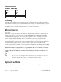
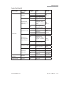
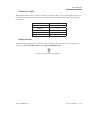
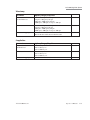
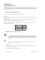
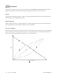
Power Outputs
COAG
U/S
BF
7.5 W
100 Ω
1 MHz
BF
35 W
900 Ω
28.5 kHz
Training
Following system installation at a surgical facility, Bausch + Lomb personnel will provide on-site training to
users who will operate the system. The training includes system startup, accessories and connections, priming
and settings adjustment consistent with the instructions provided in this user manual. Subsequent training is
provided for new staff, when the system is upgraded, or as requested by the facility.
Manual Concept
Bausch + Lomb designs manuals to give you the information you need when you need it, without having to
search for it.
This manual is organized so that in the first chapter you will find enough information to quickly get up and
running, and get answers to general questions about the Stellaris® PC Vision Enhancement System. We
have included plenty of pictures so you can grasp concepts quickly. Be sure to read Chapter 2 to become
familiar with the Graphical User Interface and the Foot Control. These are your connections to operate the
system. Chapter 3 describes information on how to customize the system to suit your particular needs.
Chapter 4 has detailed information about each function and feature, how to set up the function and its
associated disposables, and how to interact with each function. Chapter 5 provides cleaning and sterilization
information. These chapters are meant to serve as a reference to questions of a more technical nature.
Chapter 6 through Chapter 8 contain information that you may rarely need, such as unpacking, installing
modules, system check-out, meanings of error messages, service information, and system specifications. Make
sure that you read and follow all safety precautions set forth in this manual. Information presented in
this manual relating to surgical procedures is a suggestion only, and does not constitute any warranty
of fitness or claim of responsibility, or undertaking of liability resulting from any surgical techniques
practiced. The surgeon is ultimately responsible for determining the appropriate procedure for each
patient.
Note:
The user interface screens displayed in this manual may differ from what is on your system
depending on configuration. While the information is the same, the depiction may change. The
illustrations should not be used in place of the instructions in the manual.
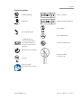
Symbols and Notes
The following are general definitions of the symbols and precautions used on this equipment and in this manual.
Preface-2
Operator’s Manual
110017276EN Rev. B
Preface
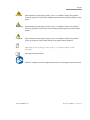
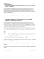
DANGER:
Calls attention to an operating procedure, practice, or condition, which if disregarded or
incorrectly performed, could result in imminent explosion hazard and risk of death or serious
injury.
WARNING:
Calls attention to an operating procedure, practice, or condition, which if disregarded or
incorrectly performed, could result in serious and/or permanent injury to personnel and/or
patients.
CAUTION:
Calls attention to an operating procedure, practice, or condition, which if disregarded or
incorrectly performed, could result in damage to the product and/or equipment.
Note:
Calls attention to an operating procedure, practice, or condition providing essential
information.
Consult operating instructions.
Caution or warning to consult accompanying documents to avoid patient or operator hazard.
110017276EN Rev. B
Operator’s Manual
Preface-3
Preface
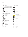
Direct Current
Alternating Current
Equipotential
Ground
Foot Control
Remote Control Reception Indicator
(Foot Control On/TruLink®
Customer Support Network Access)
Battery
Dispose of Properly
Battery Condition Indicator
Serial Number
Manufacturer
Authorised Representative
in the European Community
Date of Manufacture
Non Ionizing
Electromagnetic
Radiation
Caution: Consult
Accompanying Documents
Frequency in Hertz
Type BF Applied Part
Fuse
Coagulation
Microscope Camera
High Speed Vitrectomy
Ethernet
Monitor
Ultrasound
Stellaris® PC
Vision Enhancement System.
USB
Preface-4
Operator’s Manual
Ω
VA
A
Ohms
Volt Amps
Amperes
110017276EN Rev. B
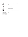
Preface
Posterior Functions
Fluid/Air Exchange
EtO gas sterilized
Illumination
Gamma Irradiation Sterilized
Do Not Reuse
Viscous Fluid Control
Do Not Re-Sterilize
21 CFR 801.109 (b)
Caution: Federal (USA)
law restricts this device to
sale by or on the order of a
physician
Do Not Use If Damaged
Member Green Dot Scheme
Transport Symbol.
See page 1-30.
No Latex
Caution: Consult
Accompanying Documents
110017276EN Rev. B
Operator’s Manual
Preface-5
Preface
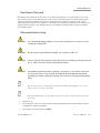
Always wear eye protection or face mask when installing or removing the
lamp
Warning: Hot surface
Electrostatic-sensitive device
Never touch the silica glass bulb of the lamp with bare hands
Xenon
Xenon-Mercury
Preface-6
Operator’s Manual
110017276EN Rev. B
Contents
1.
2.1.
2.2.
2.3.
2.4.
2.5.
2.6.
2.7.
2.8.
2.9.
2.10.
2.11.
2.12.
2.13.
2.14.
2.
3.1.
3.2.
3.3.
3.4.
3.5.
3.6.
3.7.
3.8.
3.
4.1.
4.2.
4.3.
4.4.
4.5.
4.6.
4.7.
4.8.
Getting Started
Components Shipped with the System..................................................................................................... 1-2
Connections and Setup ............................................................................................................................ 1-2
System Description .................................................................................................................................. 1-5
Setting Up Your System ........................................................................................................................... 1-6
Starting a New Procedure ...................................................................................................................... 1-15
Using Your System in Surgery ............................................................................................................... 1-21
Concluding a Surgical Procedure........................................................................................................... 1-23
Shutting Down the System..................................................................................................................... 1-27
Power Interruptions ............................................................................................................................... 1-27
Moving Your System to Another Location ............................................................................................. 1-28
System Components .............................................................................................................................. 1-29
Foot Control........................................................................................................................................... 1-38
Illumination Function ............................................................................................................................ 1-59
Multimedia Center (MMC) (optional) ................................................................................................... 1-62
User Interface
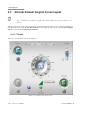
Posterior & Combined Domain Interface Controls .................................................................................. 2-1
Posterior and Combined Domain Surgical Information More Settings Screens ...................................... 2-7
Posterior and Combined Domain Surgical Screen Layouts ................................................................... 2-34
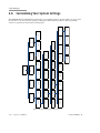
Customizing Your System Settings ........................................................................................................ 2-40
Anterior Domain Basic Interface Controls ............................................................................................ 2-40
Anterior Domain Surgical More Settings Screens ................................................................................. 2-46
Anterior Domain Surgical Screen Layout .............................................................................................. 2-67
Customizing Your System Settings ........................................................................................................ 2-75
Customizing Your System
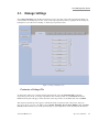
Manage Settings ...................................................................................................................................... 3-3
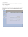
Surgeon Level Settings ............................................................................................................................ 3-9
Manage Surgeon Files ........................................................................................................................... 3-14
System Setup ......................................................................................................................................... 3-18
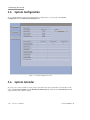
System Configuration ............................................................................................................................ 3-22
System Calendar .................................................................................................................................... 3-22
TruLink® Customer Support Network .................................................................................................. 3-24
Customization Levels ............................................................................................................................ 3-27
110017276EN Rev. B
4.
5.1.
5.2.
5.3.
5.4.
5.5.
5.
6.1.
6.2.
6.3.
6.4.
6.5.
6.6.
6.
7.1.
7.2.
7.3.
7.4.
7.5.
7.
Detailed Reference
Advanced Vacuum System Fluidics ......................................................................................................... 4-1
Posterior Functions .................................................................................................................................. 4-5
Anterior Functions ................................................................................................................................. 4-29
Coagulation Function (Posterior & Anterior Modes) ............................................................................. 4-46
Combined Domain................................................................................................................................. 4-50
Cleaning and Sterilization Requirements
Routine Cleaning ..................................................................................................................................... 5-1
Bipolar Coagulation Accessories ............................................................................................................. 5-2
Irrigation and Irrigation/Aspiration Handpieces ...................................................................................... 5-3
Ultrasound Handpiece and Accessories ................................................................................................... 5-6
Special Instructions for United Kingdom Users..................................................................................... 5-11
Cleaning the MMC ................................................................................................................................ 5-14
Troubleshooting
User Troubleshooting .............................................................................................................................. 6-1
Power Issues ............................................................................................................................................ 6-1
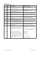
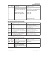
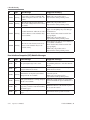
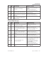
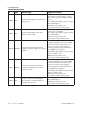
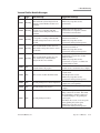
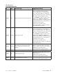
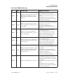
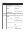
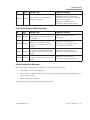
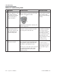
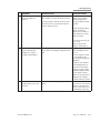
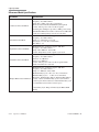
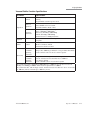
Error and Warning Messages ................................................................................................................... 6-3
Troubleshooting the MMC .................................................................................................................... 6-19
System Configurations, Modules, Accessories and Packs ..................................................................... 6-20
Service and Warranty
8.1. Service Information ................................................................................................................................. 7-1
8.2. Environmental Protection ...................................................................................................................... 7-10
8.3. Warranty Information ............................................................................................................................ 7-10
8.
Specifications
9.1. Environmental and Physical Specifications ............................................................................................. 8-1
9.2. Primary System Specifications ................................................................................................................ 8-8
9.3. System Labels ........................................................................................................................................ 8-18
9.
Glossary
110017276EN Rev. B
1 Getting Started
Getting Started
This chapter is for people who have used this type of ophthalmic vision enhancement system before and want
to use the system without reading large portions of the manual. It also provides information on setting up your
Stellaris® PC Vision Enhancement System and making the necessary connections.
DANGER:
Do not use this device in the presence of flammable anaesthetics.
WARNING:
Implantable defibrillators present a risk of injury if triggered by a fibrillatory event during
intraocular surgery, due to involuntary motion by the patient. Patients being considered for
intraocular procedures must be questioned to determine if they have such a device and, if so,
the defibrillator manufacturer must be consulted to determine the appropriate action.
WARNING:
Electromagnetic interaction between the phacoemulsification (phaco) handpiece and
an implanted cardiac pacemaker is unlikely, but cannot be ruled out. Patients should be
questioned to determine if they have such an implant and, if so, the manufacturer of the
implant should be consulted to determine the proper course of action.
WARNING:
All external wiring must be in accordance with local electrical code requirements and NEC
Class II signaling system twisted wire with outer shield. The wire length must not exceed
20 meters (60 feet). The wire gage must be 26 AWG to 12 AWG gage, with ends stripped
from 9 mm to 10 mm (3/8 inch). At no point should the wire be untwisted more than 5 cm
(2 inches).
WARNING:
Patient not to come in contact with earthing metal parts.
WARNING:
Avoid skin-to-skin contact.
WARNING:
Grounding reliability can only be achieved when the equipment is connected to an equivalent
receptacle marked “Hospital Only” or “Hospital Grade.”
110017276EN Rev. B
Operator’s Manual
1-1
1 Getting Started
WARNING:
To avoid risk of electric shock, this equipment must only be connected to a supply mains with
protective earth.
Note:
Preventative scheduled maintenance is recommended once a year to insure that the
Stellaris® PC Vision Enhancement System meets it optimum performance, reliability
and safety standards set by the manufacturer. The maintenance shall be done by a
Bausch + Lomb certified individual only.
1.1. Components Shipped with the System
Before unpacking, inspect all packages for damage. Report any damage from shipping to the carrier. Before
discarding packaging material, assure all parts are accounted for. Smaller parts may be attached to packing
materials.
Standard components shipped with the system include:
•
System Main Console
•
Foot Control with Battery
•
Foot Control Wall Charger
•
Extra Foot Control Battery
•
Foot Control Backup cable
•
Operator’s Manual (CD)
•
System Power Cord
•
Mayo Tray
•
Foot Control Battery Charging Cradle
•
Air Hose
•
Zero Level Bottle Hanger
1.2. Connections and Setup
WARNING:
1-2
For optimum aspiration and reflux performance, the patient’s eye must be at the same level as
the Stellaris® PC Vision Enhancement System aspiration port. If this is not possible, use the
patient eye level offset feature in the programming screen.
Operator’s Manual
110017276EN Rev. B
1 Getting Started
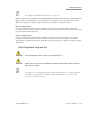
Note:
The out-of-factory Wireless System Setup is Disabled. Performing a software upgrade
will also reset the Wireless System Setup to Disabled. To setup wireless operation, see
Wireless Foot Control Operations System Setup on page 1-46.
The Stellaris® PC Vision Enhancement System is pre-configured at the factory to minimize setup and
installation requirements.
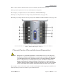
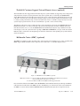
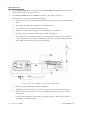
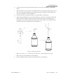
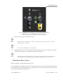
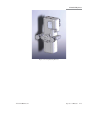
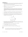
The power cable, Foot Control and Ethernet connections are located at the lower rear of the system.
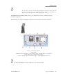
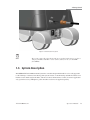
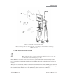
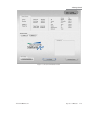
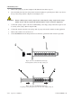
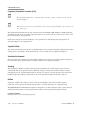
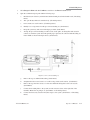
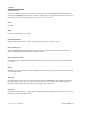
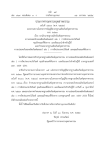
Figure 1.1. Lower Rear of System.
1. Fuse Holder.
2. Main Power Switch, disconnects system from mains voltage. See IEC 60601-1, paragraph 8.6.7
3. Ethernet Port. 4. Foot Control Backup Cable Port.
5. Power Cord Input. 6. Power Cord Retention Clip. 7. Potential Equalization Connector.
Note:
Turning off the Main Power Switch will disconnect the system from mains.
110017276EN Rev. B
Operator’s Manual
1-3
1 Getting Started
Foot Control
The Foot Control can use either wired or wireless communication. The first time the Stellaris® PC Vision
Enhancement System is used, you must use the wired connection to establish communication between the Foot
Control and the Stellaris® PC Vision Enhancement System.
For wired communication, connect the Foot Control backup cable from the back of the Foot Control to the
lower rear of the Stellaris® PC Vision Enhancement System.
Ethernet Cable (optional)
The Ethernet cable connection only applies to a Stellaris® PC Vision Enhancement System with TruLink®
Customer Support Network enabled, when you intend to upload system information to the Bausch + Lomb
Global Service Support server. No Ethernet cable is supplied with the system.
If you plan to use the TruLink® Customer Support Network, connect an Ethernet cable from the back of the
Stellaris® PC Vision Enhancement System to the wall network port before powering up the system, and
disconnect it after the system is powered down.
When the Ethernet cable is not in use, install the attached protective cap into the open socket.
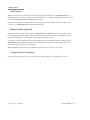
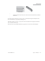
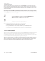
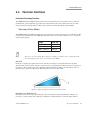
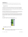
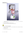
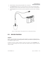
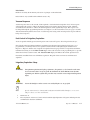
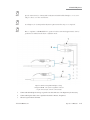
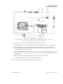
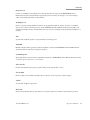
Compressed Air Connection
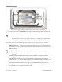
Connect the external air hose to the rear of the system as shown, and then to an appropriate air source.
1-4
Operator’s Manual
110017276EN Rev. B
1 Getting Started
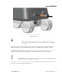
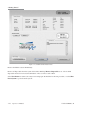
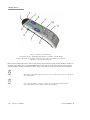
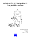
Figure 1.2. Back bottom of system.
Note:
The system requires filtered medical grade air or medical grade nitrogen, at 72.5 to
100 psig (500 kPa to 690 kPa or 5.0 to 6.9 bar) and a flow rate of 2.25 SCFM
(63.7 SLPM).
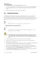
1.3. System Description
The Stellaris® PC Vision Enhancement System has a modular design which enables it to be easily upgraded
to take advantage of advances in technology. The system consists of a main housing unit which contains a user
interface screen and the surgical modules, and a Foot Control, infrared remote control (for anterior application
only, optional accessory). Handpieces, packs and other accessories are supplied separately.
110017276EN Rev. B
Operator’s Manual
1-5
1 Getting Started
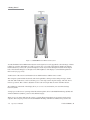
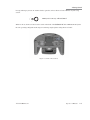
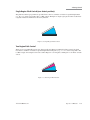
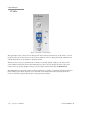
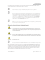
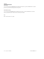
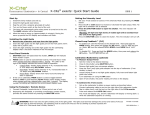
Figure 1.3. Stellaris® PC Vision Enhancement System
Your Stellaris® PC Vision Enhancement System was designed to be easily upgraded to take advantage of future
technology evolution. It includes an 19 inch, 5:4 aspect ratio color touch screen display which is the primary
interface between you and your system. The display console may be tilted 10 degrees forward and 15 degrees
back, and swiveled 90 degrees to the right or left. The brightness of the display is controlled through the A/V
More Screen (see page 2-28).
At the bottom of the screen is an infrared receiver which interfaces with the remote control.
The computer system includes both audio and visual capabilities, which provide warning messages, alarms,
and other audio indications, as well as allowing you to view setup screens surgical settings, and video from a
microscope camera. The volume is adjustable via the touch screen spin buttons on the A/V More Screen.
Two USB ports on the back of the display allow you to save, load, and transfer your customized settings
between systems.
A single port on the front of system provides filtered atmospheric air for both Fluid/Air Exchange (F/AX) and
Air Forced Infusion (AFI) for posterior and combined surgery.
There are two air outputs built into the system, to provide filtered atmospheric air for anterior and posterior
surgeries. The front port provides air for both Fluid/Air Exchange and Air Forced Infusion in posterior and
1-6
Operator’s Manual
110017276EN Rev. B
1 Getting Started
combined surgery. The port near the IV Pole on the back of the system provides air for Pressurized Infusion (PI)
in anterior surgery.
The system can be set for either gravity infusion or infusion using pressurized air (AFI and PI, respectively)
through the Infusion Tab of the More Settings Screen or through the programming interface (see Chapter 3).
Both air output ports have lighted rings surrounding them. The ring light will be solidly lit if that function is
active and within correct pressure range. If the pressure moves outside of the specified range, the ring will begin
blinking. If the pressure remains outside the set range, an error message will appear on the screen.
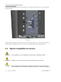
1.4. Setting Up Your System
DANGER:
Do not use in the presence of flammable anaesthetics, disinfectants, aerosol sprays, or in an
oxygen rich atmosphere.
WARNING:
This system should only be operated by personnel who have been trained and are qualified to
use this system.
WARNING:
Do not manually force the IV Pole downward if the system is on.
WARNING:
Do not modify the pole height or manually force the pole height, as this could cause an
incorrect indication of the bottle height, leading to patient injury.
WARNING:
When using gravity infusion, the ophthalmic irrigation source shall be at or above the
patient’s eye level to avoid patient injury.
CAUTION:
Do not block air vents.
Note:
110017276EN Rev. B
Do not add unapproved accessories that modify the effective IV pole height.
Operator’s Manual
1-7
1 Getting Started
Before the first use of the Stellaris® PC Vision Enhancement System, connect the Foot Control to the system
with the Foot Control backup cable provided with the system.
The following pages contain an overview for setup and use of your Stellaris® PC Vision Enhancement System
in a typical cataract surgery. This information is intended for use by someone who is already familiar with this
type of system.
Turning System On
Plug the power supply cord into the wall. Connect the compressed air hose to the system.
If desired, connect the Ethernet cable to the port at the bottom of the Stellaris® PC Vision Enhancement
System, and the other end to the hospital network port. If you have the optional MMC system, this cable should
be connected to the MMC, and the MMC in turn connected to the hospital network port. Refer to page 1-39 for
detailed MMC setup instructions.
Turn on the switch at the bottom of the system console.
WARNING:
Ensure that the power cord is routed away from traffic areas to prevent accidental
disconnection or tripping hazards.
CAUTION:
Do not turn this switch off until the system has been properly shut down.
CAUTION:
Do not disconnect system from power while in use.
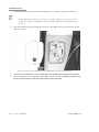
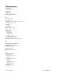
Connect the air supply to the back bottom of the system.
CAUTION:
1-8
Observe system diagnostic messages when powering up system for first use each day and take
appropriate action if required. Also observe first cassette priming or calibration, phaco/frag
handpiece tuning and/or vitrectomy handpiece testing for correct completion.
Operator’s Manual
110017276EN Rev. B
1 Getting Started
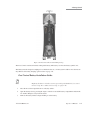
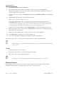
Figure 1.4. Back bottom of system.
1. Main Power Switch.
Note:
The system requires filtered medical grade air or medical grade nitrogen, at
72.5 to 100 psig (500 to 690 kPa or 5.0 to 6.9 bar) and a flow rate of 2.25 SCFM
(63.7 SLPM).
Press the power button on the front of the system, and wait for the screen to come on and the animation to
finish. The front power switch is brighter when the system is off, and dims when you turn the system on.
The Stellaris® PC Vision Enhancement System performs a self-check each time the power is turned on. The
system automatically checks its configurations for any changes since the last time it was turned on.
Note:
When turning the system on for the first use of the day, pay close attention to any warning messages
that appear on the screen and address any issues.
After the Foot Control has been synchronized to the specific Stellaris® PC Vision Enhancement System. (See
page 1-40), you may use wireless communication.
110017276EN Rev. B
Operator’s Manual
1-9
1 Getting Started
Note:
The out–of- factory Wireless System Setup is “Disabled”. Software upgrade will also
reset the Wireless System Setup to “Disabled”. See System Setup Instructions on
page 1-46 to configure Foot Control to wireless operation.
If you are going to use the Foot Control in wireless mode, ensure the Foot Control battery is charged, then hold
down any button on the Foot Control until the green ready light comes on, indicating that communication has
been initiated. This light will turn solid green when full communications have been established.
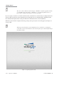
When the system check is completed following system power-up, the Splash screen will appear (See Figure 1.5
on page 1-10).
Note:
Following system shut down, wait a minimum of 15 seconds before restarting the
system. The system is fully shut down after the front panel power button light changes
from dim to bright.
Figure 1.5. Opening Splash Screen.
1-10
Operator’s Manual
110017276EN Rev. B
1 Getting Started
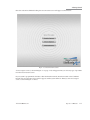
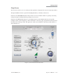
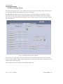
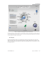
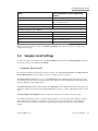
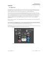
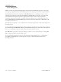
Once the software has finished loading, the Select Procedure screen will appear as shown below.
Figure 1.6. Select Procedure Screen.
A Select Surgeon Screen (as shown in Figure 1.7 on page 1-12) will appear when you select any type of procedure
from the Select Procedure Screen.
If your system is programmed to default to either the Anterior Domain, Posterior Domain or the Combined
Domain, the Select Procedure Screen will not appear, and the system will move directly to the Select Surgeon
Screen, as shown in Figure 1.7 below.
110017276EN Rev. B
Operator’s Manual
1-11
1 Getting Started
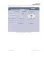
Figure 1.7. Select Surgeon Screen.
Select Surgeon
Selecting Go To Surgery option will advance the system to the Setup Screen, using the system’s default
parameters.
Touch the name of a surgeon on the list to highlight it. Then select Confirm to load the parameters for that
surgeon and advance to the Setup Screen.
Note:
If the Confirm button is not active, this indicates one or more modules were not
detected in the system and further operation is not allowed.
To set up default parameters for a new surgeon instead of using an existing surgeon’s file, select Create New.
This will allow you to setup a file for a new surgeon, using parameters from an existing surgeon as a template.
1-12
Operator’s Manual
110017276EN Rev. B
1 Getting Started
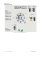
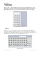
Setup Screen
The Setup Screen allows you to set certain procedure parameters, and prepare the system for surgical procedures.
The Open Pack/Insert Cassette option will be highlighted when you initially see this screen.
If desired, select Select Room (Anterior Only) and choose the case number, number of operating rooms being
used by the surgeon, and the particular operating room to be used.
If desired, select Select Case (Anterior) or Case Menu (Posterior and Combined) and choose the specific
technique, needle, grade and pathology (Anterior Domain) or vitrectomy gauge, fragmentation needle (Posterior
Domain) for the current procedure. The appearance of this screen will differ for the three possible domains, as
shown in Figure 1.8.
Figure 1.8. Anterior Domain Select Case Screen.
110017276EN Rev. B
Operator’s Manual
1-13
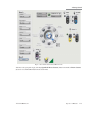
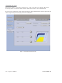
1 Getting Started
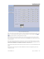
Figure 1.9. Posterior Domain Case Menu Screen.
1-14
Operator’s Manual
110017276EN Rev. B
1 Getting Started
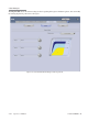
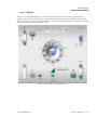
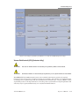
Figure 1.10. Combined Domain Case Menu Screen.
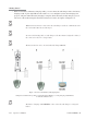
Advance to the open pack step by selecting Open Pack Insert Cassette (Anterior Domain) or Insert Cassette
(Posterior or Combined Domain) from the clock menu.
110017276EN Rev. B
Operator’s Manual
1-15
1 Getting Started
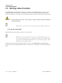
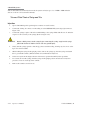
1.5. Starting a New Procedure
The Stellaris® PC Vision Enhancement System is user-friendly, and will highlight whichever step is next in
a typical procedure. The steps shown on the display screen will vary slightly depending on which optional
features are installed on your machine. On-screen instructions take precedence over information in this manual.
WARNING:
Note:
Before beginning a procedure, ensure that there is sufficient volume of irrigation solution for
the entire procedure.
Ensure tube set connection is secure when connecting to the handpiece and system.
1. Set up the sterile field.
Open the disposable pack and drop contents onto a sterile surface.
Note:
Make sure to use the proper pack for the mode you are using. Packs will not work
for other modes. The packs are color coded. Anterior packs are green and/or light
blue. Posterior Packs and Combined Packs are color-coded by needle gauge - 20 g is
black, 23 g is green, and 25 g is blue.
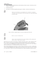
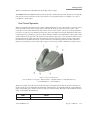
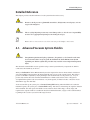
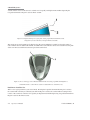
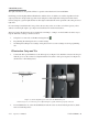
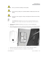
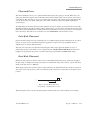
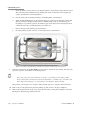
Attach the sterile screen drape by placing the drape over the top of the Stellaris® PC Vision Enhancement
System screen and secure with the adhesive strip to top, not the front, of the display as shown in the illustration
below.
1-16
Operator’s Manual
110017276EN Rev. B
1 Getting Started
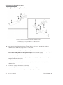
Figure 1.11. Schematic diagram of sterile draping.
1. Adhere screen drape on the top of the screen panel. 2. Screen drape. 3. Anterior Remote control drape.
4. Mayo Tray drape.
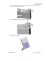
2. Setup Fluid Collection System
Note:
Ensure sufficient volume of irrigation solution is available for the procedure. The
level should be monitored during the procedure.
Insert the fluidics cassette into the slot on the front of the system and hold until it is automatically captured
by the system. The cassette housing backlight will stop blinking and remain on when the system captures the
cassette.
The system will automatically conduct a vacuum sensor and calibration check. Wait until the progress bar shows
successful completion to proceed. If the system does not pass, corrective actions will be suggested. Following
the successful cassette check, the screen will automatically advance to the Prime and Tune steps.
110017276EN Rev. B
Operator’s Manual
1-17
1 Getting Started
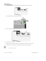
3. Connect the proper accessories to the system for an Anterior, Posterior,
or Combined procedure.
Note:
If you are using a vented Air Forced Infusion (AFI) pack, make sure to connect the
Fluid/Air Exchange filter to the F/AX port on the front of the machine.
Detailed setup instructions for each configuration are provided in Chapter 4. Use the following list to navigate to
the appropriate page and surgical setup instructions for the desired configuration.
Posterior Domain •
Vitrectomy - See page 4-7
•
Illumination - See page 4-12
•
Fluid/Air Exchange - See page 4-19
•
Viscous Fluid Injection - See page 4-24
•
Viscous Fluid Aspiration - See page 4-25
•
Linear Fluid Injection, Linear Vacuum - See page 4-27
•
Fragmentation - See page 4-28
Anterior Domain • Irrigation/Aspiration - See page 4-31
•
Phacoemulsification - See page 4-37
•
Planned Anterior Vitrectomy - See page 4-40
•
Unplanned Anterior Vitrectomy - See page 4-41
Coagulation •
Fixed Coagulation - See page 4-47
•
Linear Coagulation - See page 4-48
Combined Domain - See page 4-50
Note:
Fragmentation uses the same power connection as the ultrasound handpiece. Only
one function can be used at a time.
Note:
If a linear coagulation in set up is enabled or a Foot Control button is programmed
for coagulation, begin by plugging in the coagulation cord.
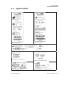
For on-screen instructions, select Show Me Steps from the Prime and Tune Screen and a tabbed screen will
appear, detailing the required steps and showing animations of how to perform each step.
1-18
Operator’s Manual
110017276EN Rev. B
1 Getting Started
WARNING:
The animations illustrate the steps but do not represent sterile technique.
4. Prime and Tune
Note:
The system will not provide feedback as to whether or not fluid is present during
priming. Inspect tubing and confirm that it is filled with fluid and free of bubbles
after each Prime and Tune. Repeat the priming process if the tubing is not adequately
filled with fluid.
When the cassette has been inserted and captured by the machine, and all accessories, tubing and handpieces
have been connected, the system is ready for Prime and Tune. To proceed to the Prime and Tune phase, select
the appropriate options for the domain in which you are operating. Available options are described below.
For Posterior Domain:
•
Select the Easy Prime button from the Prime and Tune screen to fill the left and right tubing with
BSS solution, and then perform a test of the pneumatic cutter. During this process, the gravity feed
infusion I/V pole will raise to 100 cm or lower if maximum ceiling height is set lower than 100 cm
for the anterior. In the posterior/combined domains, I/V pole will raise to the maximum ceiling height
programmed for the system. With the air pressured infusion, the pressure will raise to 73 mmHg for
anterior domain and 103 mmHg for posterior/combined domains.
•
Select the Prime/Test Vit button to activate the vacuum on right side aspiration line and test the
pneumatic vitrectomy function. The handpiece tip must be submerged in BSS during this process. After
the line has been primed, this button will become Test Vit, which will activate the cutter test without
aspiration.
•
Select the Prime/Tune U/S button to activate aspiration on the left line and tune the fragmentation
handpiece. The electric connector on the fragmentation handpiece must be inserted into the
Stellaris® PC Vision Enhancement System and the tip submerged in BSS before this option is selected.
After the line has been primed, this button will become Tune U/S, which will activate a shorter cycle
of aspiration and tuning.
•
Select the Prime/Aux button to activate aspiration to fill the left aspiration line with BSS. After the
first use, subsequent priming cycles will be slightly shorter.
110017276EN Rev. B
Operator’s Manual
1-19
1 Getting Started
For Combined Domain:
•
Select the Easy Prime button from the Prime and Tune screen to fill the left and right tubing with
BSS solution, and then perform a test of the pneumatic cutter. During this process, the gravity feed
infusion I/V pole will raise to 100 cm or lower if maximum ceiling height is set lower than 100 cm
for the anterior. In the posterior/combined domains, I/V pole will raise to the maximum ceiling height
programmed for the system. With the air pressured infusion, the pressure will raise to 73 mmHg for
anterior domain and 103 mmHg for posterior/combined domains.
•
Select the Prime/Test Vit button to activate the vacuum on right side aspiration line and test the
pneumatic vitrectomy function. The handpiece tip must be submerged in BSS during this process. After
the line has been primed, this button will become Test Vit, which will activate the cutter test without
aspiration.
•
The operation of the Prime/Tune U/S button differs, depending on which ultrasound handpiece is
connected to the system.
•
•
Fragmentation Handpiece: Select the Prime/Tune U/S button to activate aspiration on the left line
and tune the fragmentation handpiece. The electrical connector on the fragmentation handpiece
must be inserted into the Stellaris® PC Vision Enhancement System and the tip submerged in BSS
before this option is selected. After the line has been primed, this button will become Tune U/S,
which will activate a shorter cycle of aspiration and tuning.
•
Ultrasound handpiece: Select the Prime/Tune U/S button to initiate priming of the irrigation and
left aspiration line, followed by tuning of the ultrasound handpiece and a vacuum test. During this
process, the IV bottle will be raised to 100 cm or the system will use a pressure of 73 mmHg if AFI
is used. The irrigation line and the aspiration line need to be connected to the ultrasound handpiece
with the test chamber attached to the tip of the ultrasound handpiece. After the line has been
primed, this button will change to Tune U/S which will activate a shorter cycle of aspiration and
tuning without the vacuum test.
Select the Prime/Aux button to activate aspiration to fill the left aspiration line with BSS. After the line
has been primed, subsequent priming cycles will be slightly shorter.
For Anterior Domain:
1-20
•
Select the Prime and Tune button from the Prime and Tune Screen to initiate priming of the irrigation
and left aspiration line, followed by tuning of the ultrasound handpiece and a vacuum test. During this
process, the IV bottle will be raised to 100 cm or the system will use a pressure of 73 mmHg if AFI is
used. The irrigation line and the aspiration line need to be connected to the ultrasound handpiece with
the test chamber attached to the tip of the ultrasound handpiece. After the line has been primed, this
button will change to Tune Only which will activate a shorter cycle of aspiration and tuning without
the vacuum test.
•
Select the Prime Only button from the Prime and Tune Screen to initiate priming of the irrigation and
left aspiration line, followed by a vacuum test. The irrigation line and the aspiration line need to be
connected to the ultrasound handpiece with the test chamber attached to the tip of the ultrasound
handpiece. During this process, the IV bottle will be raised to 100 cm or the system will use a pressure
of 73 mmHg if AFI is used. After the line has been primed, the button will activate a shorter cycle of
aspiration without the vacuum test.
•
Select the Pneumatic Vit test to activate aspiration and a test of the pneumatic cutter.
•
In the anterior domain, the remote control can be used to activate functions in the “Prime and Tune”
window of the setup screen. The remote control UP/DOWN buttons are used to move the arrow and
select options in the “Prime and Tune” window:
Operator’s Manual
110017276EN Rev. B
1 Getting Started
“Prime and Tune”
•
•
Pressing the “Enter” button of the remote control activates the selected function as indicated
by the arrow.
•
Once Prime and Tune is initiated by any of these options, a Cancel button will appear. Selecting the Cancel
button will immediately stop the priming and tuning process.
When Prime and Tune is in progress, a progress bar at the lower left hand corner is displayed to indicate the
status of the Prime and Tune cycle.
If the system does not pass the Prime and Tune test, suggestions for corrective action will be displayed.
110017276EN Rev. B
Operator’s Manual
1-21
1 Getting Started
Figure 1.12. Prime and Tune Screen. This is an example of a posterior domain screen.
5. Advance to Surgery Phase
WARNING:
Inadvertent activation of functions that are intended for priming or tuning handpieces while
the handpiece is in the eye can create a hazardous situation that could result in patient injury.
Once the system has been successfully primed and tuned, it will automatically move to the main surgical screen.
Manually selecting Advance to Surgery produces the same result.
Note:
1-22
If the system is not primed and tuned, the aspiration, vitrectomy and ultrasound
functions will be unavailable.
Operator’s Manual
110017276EN Rev. B
1 Getting Started
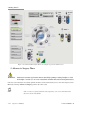
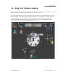
1.6. Using Your System in Surgery
Default parameters and settings are saved in the surgeon preference file, but can be modified during a procedure
using the on-screen controls and surgical settings pop-up screens (see page 2-7).
Your system will display the appropriate surgical screen for the current surgical mode. The interface is visibly
different depending on the current operational mode. See Figure 1.13 for an example of a Posterior Surgical
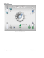
Screen, see Figure 1.14 for an example of an Anterior Surgical Screen, and Figure 1.15 for an example
of a Combined Mode Surgical Screen. When the appropriate screen appears, your Stellaris® PC Vision
Enhancement System is ready for the surgical procedure to begin.
Figure 1.13. Posterior Surgical Screen.
110017276EN Rev. B
Operator’s Manual
1-23
1 Getting Started
Figure 1.14. Anterior Surgical Screen
1-24
Operator’s Manual
110017276EN Rev. B
1 Getting Started
Figure 1.15. Combined Surgical Screen.
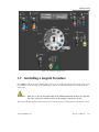
1.7. Concluding a Surgical Procedure
Select End from the clock menu. Confirm that you are ready to end the case and eject the cassette, and you will
be reminded to close the clamps on the administration tube set. A similar End function is accessible from the
Setup Screen.
WARNING:
Make sure to close the Irrigation Clamp on the Administration Tube Set before pressing End
Procedure or fluid may continue to flow from the handpiece and into the cassette.
The system will then advance to the End of Case Screen (shown below), lower the IV Pole, and eject the cassette.
110017276EN Rev. B
Operator’s Manual
1-25
1 Getting Started
Figure 1.16. Anterior End of Case Screen.
1-26
Operator’s Manual
110017276EN Rev. B
1 Getting Started
Figure 1.17. Posterior End of Case Screen.
110017276EN Rev. B
Operator’s Manual
1-27
1 Getting Started
Figure 1.18. Combined End of Case Screen.
Remove the fluidics cassette immediately.
Remove all disposables from the system. Select Show Me Steps Remove Disposables to see a list of which
disposables need to be removed, and animations of how to remove each of them.
Select Next Patient to return to the Setup Screen and prepare the machine for the next procedure, or select Shut
Down System to power down the system.
1-28
Operator’s Manual
110017276EN Rev. B
1 Getting Started
1.8. Shutting Down the System
CAUTION:
Never turn the power switch off or disconnect the power without proper system shutdown.
Equipment damage can occur.
From the System End Screen, select Shut Down System. Select Yes to confirm shut down, or No to go back to
the End Screen. The system may take a few minutes to shut down. The front panel light will glow brighter when
shut down is complete.
If you have the TruLink® Customer Support Network option enabled, the system will ask if you want to upload
system data to the Enterprise Server. Ensure the Ethernet cable is connected from the port at the bottom of the
Stellaris® PC Vision Enhancement System to the hospital network port before attempting to upload data. The
system will send diagnostic data (no patient data is transferred), then shut down when finished.
When shutting down the system, make sure to recharge the Foot Control, as described on page 1-51.
1.9. Power Interruptions
If the Stellaris® PC Vision Enhancement System requires continued operation during power main interruptions,
the system should be powered from an uninterruptible power supply (not provided).
In the event the power source is interrupted causing the system to shut down, the cassette will be ejected
automatically. Perform the steps listed below according the type of surgery.
Anterior Segment surgery:
Remove the handpiece from the eye safely and pinch off the irrigation clamp to stop fluid flowing into the
cassette.
Posterior segment surgery:
Remove handpiece from the eye safely, use sclera plugs to stop fluid leakage from the eye. Pinch off irrigation
clamp only after sclera plugs have been inserted to prevent fluid leakage. When the power supply resumes; reboot the system, insert a cassette, open the irrigation clamp and perform
prime and tune according the system setup procedures (see page 1-19). 110017276EN Rev. B
Operator’s Manual
1-29
1 Getting Started
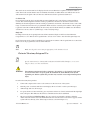
1.10. Moving Your System to Another Location
WARNING:
Do not transport or move your system from room to room or up an inclination unless you
have followed the steps below.
This unit is designed to provide mobility within the environment of the operating room.
Care must be taken as to avoid sloped floors greater than 5 degrees angle during use.
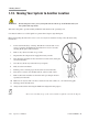
Before transporting the unit from room to room or for any more extensive moving, follow the basic safety
instructions:
1.
Power down normally by selecting “Shut Down” from the end of case
screen or pressing and holding the front button for at least 8 seconds,
ensuring the IV pole is fully retracted.
2.
Remove any objects from mat on top of unit.
3.
Depressurize the compressed air supply that feeds your unit.
4.
Disconnect the pneumatic air hose from the lower left corner (facing the
rear end of the unit)
5.
Store the tray all the way in the unit’s tray receptacle.
6.
Fully close the front drawer.
7.
Roll the power cord in its proper hooks at the rear end of the unit.
8.
Place the foot control on its dedicated hook, at the rear end of unit.
9.
Remove the bottles and tube sets from the unit’s pole hanger and store
separately from the unit.
10.
Make sure no objects such as air hose, electrical cord, video cables, etc... lie in the moving path.
11. Disengage the front brake lever.
12.
Note:
1-30
Always maneuver the unit using the handle bar designed for this purpose.
Do not store anything on top of the system, and do not pull the system by the IV pole.
Operator’s Manual
110017276EN Rev. B
1 Getting Started
1.11. System Components
The Stellaris® PC Vision Enhancement System has an advanced modular design with independent modules
concealed in a uniquely designed exterior housing. The top level of the system is the user interface screen and
computer unit. The surgical modules are concealed inside the main housing and strategically positioned to
provide optimum user interaction and surgical functions. The Foot Control is connected to the system by either
wired or wireless connections.
WARNING:
Use only handpieces, cables, tube sets and accessories designated by Bausch + Lomb for use
with this system.
WARNING:
Manufacturers of cardiac pacemakers advise against use of bipolar cautery devices on
patients with such implants. When conducting surgery on such a patient, a battery-powered
thermal cautery may be used, or the manufacturer of the pacemaker should be consulted to
determine appropriate steps to take in order to use the bipolar cautery function.
WARNING:
Manufacturers of implantable defibrillators recommend that these devices be temporarily
disabled when using bipolar cautery on patients with implants. The surgeon should determine
if the patient has such a device and consult the manufacturer for appropriate actions.
110017276EN Rev. B
Operator’s Manual
1-31
1 Getting Started
User Interface Screen
The User Interface Screen is the way the user communicates with the system. See Chapter 2 for basic user
interface controls. Technical specifications can be found in Chapter 8. A typical interface setup screen is shown
below.
Figure 1.19. Typical interface screen.
1-32
Operator’s Manual
110017276EN Rev. B
1 Getting Started
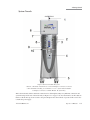
System Console
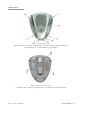
Figure 1.20. Front of Stellaris PC system.
1. IV Pole. 2. Pneumatic Actuation Port. 3. Posterior Handpiece Connectors. 4. Drawer.
5. One-Touch Wheel Locking. 6. User Interface screen. 7. System Switch “On/Off”.
8. Handpiece Connectors. 9. Fluidic Module. 10. System Tray.
This is the main unit, which contains the connections for all handpieces, Mayo tray, Ethernet connection and
system housing. On the rear of the main unit (see Figure 1.21 on page 1-34), near the IV Pole, are three buttons
that move the IV Pole up, down or back to the preset height for the current mode of operation. The console also
contains the power supply.
110017276EN Rev. B
Operator’s Manual
1-33
1 Getting Started
For systems left idle more than seven days, the Foot Control must be charged for six hours before use to ensure
proper operation.
CAUTION:
To prevent loss of data, save data before the system shuts down.
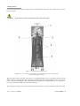
Figure 1.21. Stellaris PC System Rear View.
1. USB Port Access. 2. IV Pole Control Buttons. 3. Cord Wrap Hooks. 4. Foot Control Hook.
5. Air Pressure Output connector.
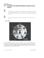
The front of the system (see Figure 1.22 on page 1-35) contains multiple ports for connecting system accessories.
There are five ports down the left side of the system, of which only the second and third are active. The second
port is for ultrasound handpieces (phacoemulsification and fragmentation) and the third port is for coagulation
(see page 1-35). The remainder are reserved for future use.
The single port at the top of the cassette housing provides air pressure to drive the pneumatic vitrectomy cutter.
1-34
Operator’s Manual
110017276EN Rev. B
1 Getting Started
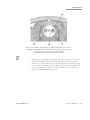
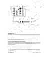
There are 4 ports down the right side of the system for connecting specific system accessories.
The first port (6 in figure below) is for Viscous Fluid Injection & Aspiration.
The second port (7 in figure below) is for air forced infusion and Fluid/Air Exchange.
The third port (8 in figure below) is for lamp 2 and provides illumination. (See page 1-61)
The fourth port (9 in figure below) is for lamp 1 and provides illumination with selectable filters. (See page 1-61)
Figure 1.22. Front panel with handpiece connectors.
1. Reserved for future use. 2. Ultrasound. 3. Coag. 4. Reserved for future use. 5. Reserved for future use.
6. VFC. 7. F/AX and AFI 8. Lamp 2. 9. Lamp 1.
Ultrasound Functions (Phacoemulsification and Fragmentation)
WARNING:
Manufacturers of implantable defibrillators recommend that these devices be temporarily
disabled when using phacoemulsification or systems on patients with these implants. This is
especially important when using pulsed phaco modes of operation. Although the implanted
devices are designed to reject electromagnetic interference, and Bausch + Lomb Vision
Enhancement equipment is designed to minimize such interference, a chance interaction
cannot be ruled out. Patients should be questioned to determine if they have such an implant
and, if so, the manufacturer should be consulted to determine the proper course of action.
The second port on the left side of the system is for ultrasound handpieces. These support phacoemulsification
and fragmentation procedures in continuous, pulsed, and burst modes.
110017276EN Rev. B
Operator’s Manual
1-35
1 Getting Started
Coagulation
The third port on the left side of the system is for a coagulation handpiece which provides coagulation power in
either Fixed or Linear modes. See page 4-46 for details of use and page 8-13 for technical specifications.
The front of the system contains a total of ten ports for connecting system accessories. Only some ports are
active, the remainder are reserved for future use.
Foot Control
The Foot Control contains the Footpedal and four programmable buttons, and provides the main interface
between the user and the vision enhancement system for controlling most functions. The Foot Control can
be used in a wired or wireless mode. See page 1-40 for detailed instructions for its use and page 8-10 for technical
specifications.
Fluidics Function
This function uses a vacuum-based pump to control the output vacuum range from 0 to 600 mmHg, and uses a
rigid 300 ml collection cassette with attached irrigation and aspiration tubing. Pneumatic vitrectomy supports
both a Linear Cut Rate and a Fixed Cut Rate from 0 to 5000 cpm. See page 4-5 for details of posterior use and
page 8-17 for technical specifications.
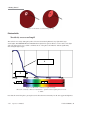
Illumination Function
The illumination function provides two light sources, both with an adjustable attenuator. More than 25 lumens
output is available at maximum settings. With a xenon lamp in Lamp 1 location, any one of three color filters
(yellow, green and amber) may be used. Both ports incorporate permanent filtration to reduce ultraviolet, violet,
deep red and infrared light. See page 4-11 for details of use and page 8-18 for technical specifications. page 1-61 gives
additional guidance on output setting.
Air Compressor
The compressor provides air pressure to drive various pinch valves, Pressurized Infusion (Anterior domain), Air
Forced Infusion (Posterior/Combined domains) and Fluid/Air Exchange. It also houses the air pump to drive
the Viscous Fluid injection function and the venturi regulator for vacuum control. See Chapter 8 for technical
specifications.
IV Pole
WARNING:
1-36
Use of an IV Pole extension or other means of altering the bottle height may cause inaccurate
setting displays resulting in serious permanent patient injury.
Operator’s Manual
110017276EN Rev. B
1 Getting Started
WARNING:
This system is to be used in either air pressured infusion mode or IV Pole mode but never
both together as high intraocular pressures may result.
CAUTION:
Do not manually force the IV Pole or use the IV Pole as a handle.
The Stellaris® PC Vision Enhancement System IV Pole is an integral part of the system console. It can be
directly moved up, down, or to a specific preset height by any of several methods. It can be controlled through
the touch screen, Foot Control (if programmed), remote control (optional accessory), or directly by using the
buttons on the back of the system console. The IV Pole can also be pre-programmed to a certain height for
various surgical modes. The system will not compensate if the bottle height is altered though the use of IV Pole
extensions or other hardware not provided with the system.
To change the bottle height during surgery, use the up and down arrows on the IV Pole control section of the
Surgical Screen (See page 2-39), or use the buttons on the back of the system console.
In the lowest (stowed) position and with a 500 ml bottle, the IV Pole will provide approximately 30 cm. (12 in.)
of infusion pressure, measured from the aspiration port to the middle of the BSS drip chamber. This is an
equivalent pressure (not Intraocular Pressure) of 22.4 mmHg. The IV Pole can extend to 140 cm (55 in.) high,
an equivalent pressure of 102.74 mmHg.
To change the programmed bottle height settings for the current surgical mode, select the Fluidics More
Settings Screen (page 2-32) if in Posterior Mode, or the Vacuum Fluidics More Settings Screen (See page 2-19), then
select the Infusion Tab to change the actual height, preset height, or the maximum the IV Pole is allowed to
reach.
The maximum IV Pole height should be set when installing the Stellaris® PC Vision Enhancement System in a
particular medical facility. You can do this using the programming interface (see Chapter 3).
Remote Control (Anterior Domain Only, Optional Accessory)
CAUTION:
The remote control is not waterproof and is not sterilizable. The remote control must be
placed in a sterile cover prior to use in the sterile field.
The remote control transmits an infrared signal to a receiver at the bottom of the touch screen. For critical
functions you can activate a command directly through the remote control. The commands which may be given
from each remote control button are shown in Figure 1.23 on page 1-38.
The remote control is powered by two AA batteries, which should be replaced when the low battery light comes
on. Access the remote control batteries by removing the battery cover on the back of the remote.
110017276EN Rev. B
Operator’s Manual
1-37
1 Getting Started
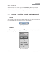
Figure 1.23. Remote Control functions.
1. Low Battery Light. 2. Transmitting Signal Light. 3. Next Phase. 4. Bottle Height.
5. Phaco/Vitrectomy or Coagulation. 6. Up and Down. 7. Flow. 8. Vacuum. 9. Previous Phase.
10. Enter. 11. Reserved for Future Use.
In the anterior domain, the remote control can be used to activate functions in the “Prime and Tune” window of
the setup screen. The remote control UP/DOWN buttons are used to move the arrow and select options in the
“Prime and Tune” window. Pressing the “Enter” button on the remote control activates the selected function.
Note:
The batteries should be removed from the remote control if the system is to be idle for
more than 30 days.
Note:
It is your responsibility to dispose of batteries in a safe and environmentallyresponsible manner in accordance with local regulations.
1-38
Operator’s Manual
110017276EN Rev. B
1 Getting Started
TruLink® Customer Support Network Remote Access (optional)
The TruLink® Customer Support Network feature improves system reliability by supporting remote diagnostics
and performance analysis. System performance data, but no patient data, is collected by the Stellaris® PC
Vision Enhancement System throughout the surgical day. Upon system shut down, that information can be sent
to Bausch + Lomb secure servers through an encrypted, point to point connection. This allows Bausch + Lomb
to analyze system performance, help you remotely (where this service is available), and proactively service the
system. Surgeon preference files can also be transmitted, to provide a secure off-site backup.
The Ethernet cable that is used to transfer the data can be permanently connected to the Stellaris® PC Vision
Enhancement System, or it can be connected at the end of each surgical day just before shutting down, and
then disconnected to move or store the Stellaris® PC Vision Enhancement System. Upon shutdown from the
End of Surgery screen, the system will offer a prompt to Send data to TruLink. If you agree, make sure that the
Ethernet cable is connected to the designated port and follow instructions. After updating, the system will shut
down automatically.
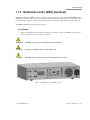
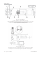
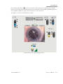
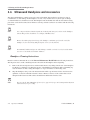
Multimedia Center (MMC) (optional)
The MMC (if available) provides streaming video on the surgical screen and microscope overlay capability. The
MMC supports NTSC and PAL format composite video and S-video, or a FireWire digital camera.
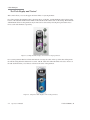
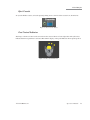
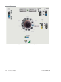
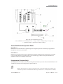
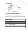
Figure 1.24. Multimedia Center (MMC) (optional).
1. Main Power Switch. 2. Connection Indicator LED from Stellaris® PC Vision Enhancement System.
3. Connection Indicator from microscope camera.
4. Connection Indicator LED to TruLink® Customer Support Network.
Data is transferred between the MMC and the Stellaris® PC Vision Enhancement System through an Ethernet
cable that runs from the back of the MMC system to the Ethernet port on the bottom of the system. Whenever
the MMC is on and connected and the Stellaris® PC Vision Enhancement System is in surgical mode, the
110017276EN Rev. B
Operator’s Manual
1-39
1 Getting Started
current video image will appear on screen in the center of the Clock Menu. You can touch the video image
itself to toggle between small and large display sizes. You can also touch the outer edge of the video display to
toggle between the video display itself and an animation showing the effect of the handpiece in the eye for the
currently selected phase.
If the system has the optional MMC, the TruLink® Customer Support Network can be activated by connecting
the Ethernet port on the MMC to a designated Internet-enabled network connection and enabling the TruLink®
Customer Support Network data download upon shutdown or Remote Access function (if available in your area)
on the Stellaris® PC Vision Enhancement System.
Note:
An off-the-shelf Ethernet cable may be used with the Stellaris® PC Vision
Enhancement System to establish or restore connections.
Note:
The MMC is not intended for diagnostic purposes.
Before installing the Multimedia Center, please take note of the following:
•
Multimedia Center must be installed outside of the sterile field.
•
Do not place BSS bottles or other containers of fluid on top of the Multimedia Center.
•
The AC power source for the Multimedia Center must have a Ground Fault Interrupt.
1.12. Foot Control
The Foot Control is the main interface between the surgeon and the Stellaris® PC Vision Enhancement System.
The surgeon can control most of the available functions from the Foot Control. The Foot Control can be
connected through a physical cable, or through a wireless Bluetooth connection. When the Foot Control cable is
not in use, make sure to install the attached protective caps into the cable ports.
This device complies with Part 15 of the FCC (U.S. Federal Communication Commission) Rules. Operation is
subject to the following two conditions: 1) this device may not cause harmful interference, and 2) this device
must accept any interference received, including interference that may cause undesired operation.
1-40
Operator’s Manual
110017276EN Rev. B
1 Getting Started
Figure 1.25. Placement of Foot Control During Storage.
The Foot Control contains an internal, rechargeable battery. The battery cover has the battery symbol on it.
The battery must be charged overnight prior to initial wireless use, or if the system is idle for more than seven
days. Refer to the battery charging options section on page 1-51.
Foot Control Battery Installation Guide:
Note:
Replacing the battery when the system is powered up will disable the foot control
wireless set up. To re-enable wireless set up, see page 1-46.
1.
Place the Foot Control upside down on a flat, dry surface.
2.
Open the battery door by pressing the targets on the door toward the battery compartment and turn the
two latches 90 degrees away from the center.
3.
Remove the battery with two fingers holding on to the battery.
110017276EN Rev. B
Operator’s Manual
1-41
1 Getting Started
4.
Before installing the replacement battery, check the battery electrical contacts to ensure they are clean
and free of contamination.
5.
Install the new battery.
6.
Press the door toward the compartment and engage door latches to securely close the battery door.
Note:
Following system shut down, wait a minimum of 15 seconds before restarting the
system. The system is fully shut down after the front panel power button light changes
from dim to bright.
Figure 1.26. Battery compartment with recess (arrows) to facilitate battery replacement.
Note:
Be sure to securely close battery door.
Note:
A battery must be installed in the Foot Control at all times, while operating either
wired or wireless, to insure proper operation.
The first time a Foot Control is used, it must be connected via the back up cable to set the configuration. Once
this is set, the Foot Control will only communicate wirelessly with that specific system. To begin wireless
operation, make sure the Stellaris® PC Vision Enhancement System is on, then press any Foot Control Button
and wait communication to be established, which may take up to 10 seconds.
The ready light, identified by the symbol below, will turn solid green when the Foot Control is communicating
wirelessly with the Stellaris® PC Vision Enhancement System. During operation when system is not detecting
foot control wireless connection; the system will disable wireless operation. This happens when the system is
1-42
Operator’s Manual
110017276EN Rev. B
1 Getting Started
in setup and surgery screens. To resume wireless operation, refer to the Foot Control Wireless System setup
section.
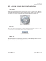
LED Symbol for Ready on Foot Control
When not in use, the Foot Control can be stored on the back of the Stellaris® PC Vision Enhancement System.
In some operating configurations the surgeon can change surgical phases using the Foot Control.
Figure 1.27. Back of Foot Control.
110017276EN Rev. B
Operator’s Manual
1-43
1 Getting Started
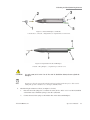
Figure 1.28. Top of Foot Control.
1. Right Toe Button. 2. Footpedal. 3. Right Heel Button. 4. Indicator Lights. 5. Right LED (Wireless).
6. Left LED (Battery). 7. Left Heel Button. 8. Left Toe Button.
Figure 1.29. Bottom of Foot Control.
1. Pedal Offset Switch. 2. Battery Compartment Door. 3. Pedal Pitch Tension Adjustment Knob.
1-44
Operator’s Manual
110017276EN Rev. B
1 Getting Started
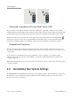
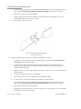
Figure 1.30. Pedal Offset Switch Indicator (4) and Pedal Offset Positions (5, 6, and 7).
4. Pedal Offset Switch Indicator. 5. Left Offset (for system setup of left foot operation).
6. Center Position (for system setup for left or right foot).
7. Right Offset (for system setup for right foot operation).
Note:
110017276EN Rev. B
The pedal offset switch indicator must align with either left, right or center pedal
offset position. Failure to align the indicator appropriately will cause the Foot
Control to become inoperable. Left or right offset position selections strictly follow
system software programming for Left or Right foot operations. For example, if the
system is programmed to right foot operation, the indicator (4) can only be set to
Center (6) or Right Offset Position (7) only.
Operator’s Manual
1-45
1 Getting Started
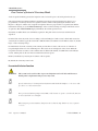
Wireless Foot Control Operations System Setup
Note:
The out–of- factory Wireless System Setup is “Disabled”. Software upgrade will reset
the Wireless System Setup to “Disabled” also.
To setup wireless operation, follow steps below:
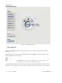
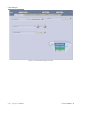
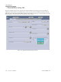
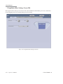
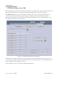
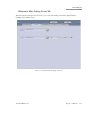
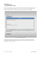
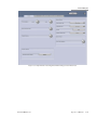
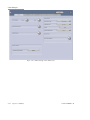
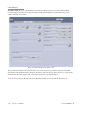
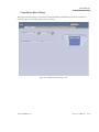
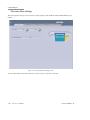
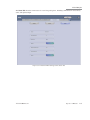
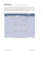
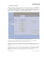
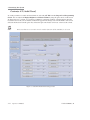
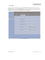
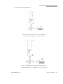
Step 1: Select “Programming” from Setup or “Select Surgeon” screens.
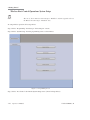
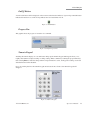
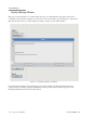
Step 2: Select “System Setup” from the programming screen, as shown below.
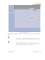
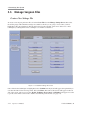
Figure 1.31. Programming Screen.
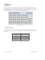
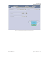
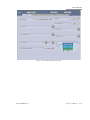
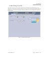
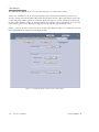
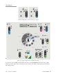
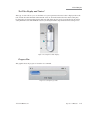
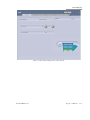
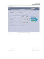
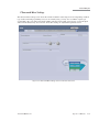
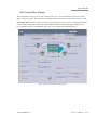
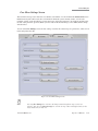
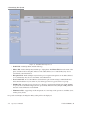
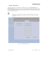
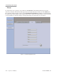
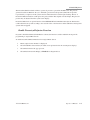
Step 3: Select “Foot Control” tab from the System Setup screen. (Arrow in image below).
1-46
Operator’s Manual
110017276EN Rev. B
1 Getting Started
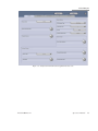
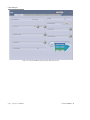
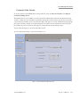
Figure 1.32. System Setup Screen.
Step 4: Select Wireless “Enabled” or “Disabled” to configure foot control connection mode. (Circled in image
above.)
Note:
The system setup is for enabling wireless functionality, it does not affect the wired
functionality. The wired option is always available and active when connected.
Note:
The system will disable wireless operation once it detects a loss of wireless
connection at the setup and surgery screens. Changing the battery at the setup and
surgery screens will also disable the wireless system setup.
110017276EN Rev. B
Operator’s Manual
1-47
1 Getting Started
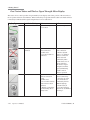
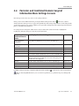
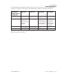
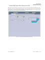
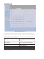
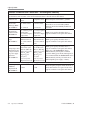
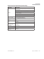
Foot Control Status and Wireless Signal Strength Meter Display
The status of foot control operation is represented by icons display at the lower portion of the screen above
the foot pedal activation status indicator. Wired connectivity is represented with a cable icon and the wireless
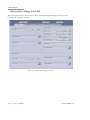
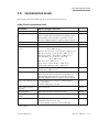
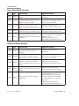
connectivity is indicated with a signal strength meter icon. See table below:
Display Type
1-48
Operator’s Manual
Foot Control Setup
Status
Action
Wired or Wireless
System detecting wired
Foot Control
No action required
Wired (Wireless
disabled)
System NOT detecting
wired connection.
Possible cause:
Foot Control cable not
connected
Wireless
System NOT detecting
wireless connection
signal.
Possible cause:
1. Foot Control wireless
function has not been
activated.
2. Wireless connectivity
not functioning due to
battery issue.
Check Foot Control
cable connection.
If Wireless System
Setup is on “enabled,”
wireless connection
will be activated
momentarily when
system detects loss of
wired connection.
The wireless signal
strength icon will be
displayed indicating
system is now in
wireless operation.
1. Initiate wireless Foot
Control connectivity
by pressing one of the
foot control buttons
momentarily, the left
LED will light up.
2. Check battery if
Foot Control wireless
function not established
after Step 1.
110017276EN Rev. B
1 Getting Started
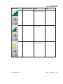
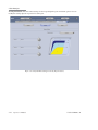
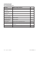
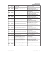
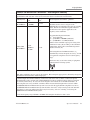
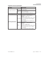
Display Type
110017276EN Rev. B
Foot Control Setup
Status
Action
Wireless
System detecting
No action required
Excellent signal strength
Wireless
System detecting Good
signal strength
Wireless
System detecting
No action required
Moderate signal strength
No action required
Operator’s Manual
1-49
1 Getting Started
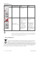
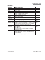
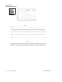
Display Type
Foot Control Setup
Status
Action
Wireless
System detecting Low
signal strength
No action required
Wireless (System
disabled wireless setup)
Note:
System lost wireless
connection signal during
procedure.
System will
automatically configure
to wired operation.
The icon remains
until connected with
Foot Control cable or
manually re-configures
system to wireless
configuration.
Connect Foot Control
backup cable to resume
operation.
Note:
System will remain in
wired configuration
the next time system
is powered up. To
configure system to
wireless operation, see
section on Wireless Foot
Control System Setup,
page 1-46.
Irrigation or infusion will be turned ON and other functions will be disabled when
the system does not detect Foot Control connectivity in surgical mode. Irrigation or
infusion can be turned OFF from the touch screen.
Battery Management
This symbol on the battery indicates that the product must be disposed of separately and safely.
Therefore, it is your responsibility to dispose of this waste equipment by handing it over to a
designated collection point or organization that specializes in the recycling of waste electrical and
electronic equipment. The separate collection and recycling of waste equipment at the time of
disposal will help conserve natural resources and ensure that it is recycled in a manner that protects both human
health and the environment. For more information about where you can drop off your waste equipment for
recycling, please contact your local recycling office or electronic waste hauler.
1-50
Operator’s Manual
110017276EN Rev. B
1 Getting Started
CAUTION:
Do not expose the battery to any fluids.
The battery, when fully charged, will last for 12 hours. You may rely on a single battery, or choose to keep one
charging in a battery charging cradle (BL4393) while the other battery is being used.
Figure 1.33. Foot Control Battery Charging Cradle.
Battery Charging Options
Note:
The battery should be removed from the Foot Control if the system is to be idle for
more than seven days.
Note:
To maximize performance, the Foot Control batteries (BL4390) should be rotated
every two months. Upon removal, battery must be charged before it is stored.
Note:
Use only Bausch + Lomb supplied wall chargers (BL4391), charging cradles
(BL4393), adapters (BL4392US, BL4392UK, BL4392EU, BL4392AUS,
BL4392ROW), and batteries (BL4390) with the Stellaris® PC Vision Enhancement
System.
The Foot Control Battery should be charged whenever the system is not in use. Any one of three methods can be
used to charge the battery.
•
With the system power cord plugged in to the electric source and the Foot Control connected to the
system; the battery will be charged if the main power switch is turned ON. This charging method
applies with or without the Graphical User Interface being turned ON. See Option 1 in Figure 1.34
•
The Foot Control can be directly connected to the wall charger. Connect the wall charger cable into the
back of the Foot Control, into the same receptacle used for the backup cable. See Option 2 in Figure
1.34.
110017276EN Rev. B
Operator’s Manual
1-51
1 Getting Started
•
With an extra battery and battery charging cradle, you can connect the wall charger cable to the battery
charging cradle. A green light indicates the cradle is on, a second light is yellow when charging is in
progress, and green when the battery charging is complete. Once the battery is fully charged, you can
take it out of the cradle and replace the battery in the Foot Control. See Option 3 in Figure 1.34.
Note:
When the Foot Control is connected to the wall charger it will not communicate with
the system and cannot be used in surgery.
Note:
To connect the backup cable or wall charger to the Foot Control, align the red dot of
the connectors to the 12 o’clock position.
Note:
The Foot Control is only to be used with wall charger BL4391.
Figure 1.34. Foot Control Battery Charging Options.
1. Using Foot Control back up cable. 2. Using wall charger BL4391. 3. Using charging cradle BL4393.
A = Electrical Power Source.
Note:
1-52
The battery charging cradle MUST be connected to the wall charger to charge the
battery.
Operator’s Manual
110017276EN Rev. B
1 Getting Started
Wireless communication is disabled when the backup cable is in place.
The Stellaris® PC Vision Enhancement System will provide a warning message when the battery is nearing the
end of its life. Call your customer service representative for a replacement battery. See Chapter 7 for a list of
local Bausch + Lomb offices.
Foot Control Operation
The Foot Control has four buttons and a center footpedal which has two axes of movement, to control two linear
functions simultaneously. The footpedal operates with both the pitch (up and down) and yaw (side to side)
travel. The yaw movement simulates the side switches used on some systems, and can be set and programmed
for left-foot or right-foot users. Reflux (if selected) is always activated by inward yaw displacement. The center
footpedal may be programmed to operate two linear functions simultaneously (Dual Linear control). The control
of linear functions is proportional to the amount of footpedal travel. See page 1-57 for description of linear control.
In single linear mode, pitch controls the linear functions selected, and yaw movement provides on/off control
in both directions. In Dual Linear mode, one linear function is controlled by pitch travel, and the other linear
function is controlled by yaw travel. The table on page 1-59 shows the possible combinations of linear control.
Figure 1.35. Foot Control, labeled.
1. Left Toe Button. 2. Footpedal. 3. Right Toe Button. 4. Right Heel Button. 5. Right LED (Wireless).
6. Left LED (Battery). 7. Left Heel Button.
There are two lights on the Foot Control itself. The light on the right indicates that the wireless connection on
the Foot Control is active. This light will flash until communications are established with the system. When the
light is non-flashing green, the Foot Control is ready to be used wirelessly. The light on the left indicates battery
status, as described in the table below.
Color
Green
110017276EN Rev. B
Status
More than one hour of battery life remains
Operator’s Manual
1-53
1 Getting Started
Color
Yellow
Red and Blinking
Status
Battery is charging
Less than one hour of battery life remains
Basic Button Operation
Note:
Voice confirmation (if enabled) responds to Foot Control and remote control
operation. For surgical phase changes, voice confirmation also will be activated if
changes are made through the touch screen.
All four buttons on the Foot Control are user programmable. They are initially set in the surgeon preferences
file, and can be modified either through the programming interface (see Chapter 3), or in some cases through the
Foot Control More Setting Screen (see page 2-24).
The Foot Control More Settings Screen is used to convey the current footpedal configuration and status to the
surgical team. In anterior domains, it is displayed by selecting the Foot Control More Button, which is the
below the Footpedal status icon on the bottom of the Main Surgical Screen and Setup Screen. In the posterior
and combined domains, the Foot Control More Settings Screen is displayed by selecting the More Settings
Screen
button.
Footpedal
The footpedal itself, located in the center of the Foot Control, provides two axes of movement and thus allows
simultaneous control of two system parameters. Both controls are programmable with respect to function and
control parameters. In the pitch direction, the footpedal will provide approximately 15° of up/down movement.
In the yaw direction, the center pedal will provide approximately 10° of travel from center in both the left and
right directions, however, the center (home) position may be set to be offset approximately 5° in either direction
as explained on page 1-56. When released, the footpedal will return to the home (up or center) position. The table
on page 1-59 shows the possible combinations of control available. The programmable detents provide tactile
feedback to the pitch movement when it moves between different regions.
1-54
Operator’s Manual
110017276EN Rev. B
1 Getting Started
Single Region Pitch Control (one detent position)
The pitch movement is programmed to provide linear control as a function of relative footpedal displacement
(e.g., 0° to 15° down corresponds to 0% to 100% output). Examples of single region pitch control are the linear
coagulation function and fixed cut vitrectomy function.
Figure 1.36. Single Region Pitch Control.
Two Region Pitch Control
There are two programmable regions (two detent positions). When programmed for linear control, the pitch
movement is a function of relative footpedal displacement in Region 2 (e.g., 5° to 15° down corresponds to 0%
to 100% output). An example is I/A control, where Region 1 is for irrigation, and Region 2 is for linear vacuum
or flow.
Figure 1.37. Two Region Pitch Control.
110017276EN Rev. B
Operator’s Manual
1-55
1 Getting Started
Three Region Pitch Control
There are three programmable regions (three detent positions). When programmed for linear control, pitch
movement is a function of relative footpedal displacement as shown below. An example is single linear
ultrasound phases, where Region 1 is irrigation, Region 2 is fixed aspiration, and Region 3 is linear ultrasound
power.
Figure 1.38. Three Region Pitch Control.
Programmable Yaw Positions
The Foot Control may be set and programmed to give greater linear yaw movement for either right or left
foot operation. Turn the Foot Control over and adjust the Pedal Offset Switch to the left or right for preferred
direction.
•
Set and programmed for a right footed operator with the pedal home position offset to the left of center
by approximately 5° to give approximately 15° of motion to the right and approximately 5° of motion
to the left. See Dual Linear Yaw Control below.
•
Set and programmed for a left footed operator with the pedal home position offset to the right of center
by approximately 5° to give approximately 15° of motion to the left and approximately 5° of motion to
the right. See Dual Linear Yaw Control below.
•
Set and programmed for a right- or left-footed operator with the pedal home position in the center
giving approximately 10° of motion in both directions.
The pedal offset switch indicator must align with either left, right or center pedal offset position. Failure to
align the indicator appropriately will cause the Foot Control to become inoperable. Left or right offset position
selections strictly follow system software programming for Left or Right foot operations.
For example, if the system is programmed to right foot operation, the indicator (4) can only be set to Center (6)
or Right Offset Position (7) only. Refer to Figure 1.39 on page 1-57.
1-56
Operator’s Manual
110017276EN Rev. B
1 Getting Started
Figure 1.39. Pedal Offset Switch Indicator (4) and Pedal Offset Positions (5, 6, and 7).
4. Pedal Offset Switch Indicator. 5. Left Offset (for system setup of left foot operation).
6. Center Position (for system setup for left or right foot).
7. Right Offset (for system setup for right foot operation).
Single Linear Setup
In Fixed Cut Vitrectomy Mode, the outward yaw movement provides ON/OFF cutting control. Each successive
outward movement toggles the programmed tool ON or OFF. In ultrasound mode, outward yaw control could be
programmed to toggle between different ultrasound submodes. When the footpedal is released, it returns to the
center position. Inward yaw movement controls reflux.
Dual Linear Setup
The outward yaw movement provides linear control of the programmed function, relative to footpedal
displacement (e.g., 0° to 15° displacement corresponds to 0% to 100% output). When the footpedal is released,
it returns to the center position. Inward yaw movement controls reflux.
Yaw Control of Reflux
The footpedal may be programmed for use with either the right or left foot. Reflux (if selected) is always
activated by inward yaw displacement. For a right foot configuration, reflux is to the left (inward). For a left
foot configuration, reflux would be to the right. Reflux may only be activated when aspiration is not activated.
Yaw Control of Ultrasound Submode
For single linear setup, the ultrasound submode sequence (if programmed) is activated by inward or outward
yaw when the footpedal is in Region 2 or Region 3. In a Dual Linear Setup, the yaw control of the ultrasound
submode can only be activated (if programmed) by inward yaw when the footpedal is in Region 2 or Region 3.
110017276EN Rev. B
Operator’s Manual
1-57
1 Getting Started
Linear Coagulation Control
The control power is varied linearly from preset minimum to the preset limit. Power begins when entering
footpedal position 1 and ends at the completion of travel.
Note:
1-58
Due to compliance with IEC 60601-2-2, position 1 will not start until approximately
35% of pedal travel is attained in the linear coagulation mode.
Operator’s Manual
110017276EN Rev. B
1 Getting Started
Center Foot Control
Phase Type
Dual Linear
Control
Disabled
Region
Pitch
R1
R2
R3
R1
R2
Irrigation
Fixed aspiration
Linear ultrasound
Irrigation
Aspiration R2
minimum to fixed
vacuum or vacuum
limit
Fixed aspiration &
linear ultrasound
Irrigation
Minimum
aspiration
Linear ultrasound
Irrigation
Aspiration R2
minimum to fixed
vacuum or vacuum
limit
Min. aspiration and
linear ultrasound
Irrigation
Linear aspiration
Disabled (with
aspiration control
feature on)
R3
Aspiration on yaw
R1
R2
R3
R1
R2
Ultrasound
Aspiration on
yaw & aspiration
control feature on
R3
R1
Aspiration on Pitch R2
Dual Linear
Ultrasound
Irrigation/
aspiration
Disabled
Irrigation Only
Disabled
110017276EN Rev. B
R1
R2
R3
R1
R2
R1
Irrigation
Fixed Aspiration
Linear U/S
Function
Irrigation
Linear aspiration
Irrigation
Yaw Out
Next
submode
Next
submode
Linear
aspiration
To max.
aspiration
Linear
ultrasound
Linear
Ultrasound
Operator’s Manual
1-59
1 Getting Started
Phase Type
Anterior
Vitrectomy
Dual Linear
Control
Region
Pitch
Disabled
R1
R2
Irrigation
Linear Aspiration
Cutter on/off
& fixed vitrectomy
when on
Irrigation
Linear Aspiration
Linear
Vitrectomy
Irrigation
Linear Vitrectomy Linear
Aspiration
Linear Aspiration
and fixed cut
Cutter On/
vitrectomy when
Off
On
No Function
Single Cut
Linear Aspiration
Single Cut
No Function
Linear cut
Linear Aspiration
Linear Cut
No Function
Linear
Linear Cut
Linear
Aspiration
Linear Aspiration
Cutter On/
and Cut
Off
Linear Coagulation
R1
Aspiration on Pitch R2
Aspiration on Yaw
Disabled (Fixed
cut)
R1
R2
R1
Disabled (Single
cut)
Posterior
Vitrectomy
Coagulation
1-60
R1
R2
Aspiration on Pitch R1
(Dual/Yaw Cut)
R2
R1
Aspiration on Yaw
R2
(Dual/Yaw Vac)
Disable (co-linear)
R1
Disabled
R1
Operator’s Manual
Yaw Out
110017276EN Rev. B
1 Getting Started
1.13. Illumination Function
General introduction to setting the correct light level
The guidelines provided in this section are based on ISO15752:2000(E), ISO15004-2:2007(E) and ISO/DIS
15752.
The Stellaris® PC Vision Enhancement System illumination system comes with a state of the art visualization
module to enhance the surgeon’s ability to see effectively during procedures. The output from the illumination
probe can attain high-lumen levels if needed; is filtered to minimize hazardous light; and is very flexible,
providing easy to access color filter options to enhance safety and tissue visibility.
As with any high intensity illumination system used in the eye, care is needed during use to reduce potential for
damage to intraocular tissues.
WARNING:
The light emitted from this instrument is potentially hazardous. Avoid concentrating the
illumination output on a small area of the retina for prolonged periods of time due to the
potential for photoretinitis and serious permanent patient injury. Set the illumination level to
the minimum needed to perform the surgical procedure.
There are two mechanisms by which harm can be induced:
•
Photoretinitis - photochemical injury to the retina resulting from intense light exposure
•
Thermal
In both cases the damage is caused by the intensity of light at a given point, normally called “irradiance” and
usually measured as power per square centimeter. This means that the risk of harm is increased when the
illumination probe is moved closer to the retina: at a distance of 5 mm from the retina the irradiance is about
twice that of the probe at 7 mm.
Figure 1.40. Irradiance as a function of distance.
For reference, the “lumens” output of an illumination probe is a measure of the total light output at the end of
a fiber. For the same lumens output, a focal probe has a higher irradiance (and hence risk of harm) than a wide
angle probe because the same total light output is concentrated into a smaller area on the retina. The lumens
measurement also takes into account the sensitivity of the human eye to different wavelengths of light.
110017276EN Rev. B
Operator’s Manual
1-61
1 Getting Started
Figure 1.41. Irradiance as a function of probe type
Photoretinitis
Sensitivity verses wavelength
The retina is more easily damaged by ultra-violet and violet-blue light than it is by light with longer
wavelengths. The Stellaris® PC Vision Enhancement System incorporates filters to remove ultra-violet light
and violet light, but it is not possible to eliminate more of the phototoxic influence without significantly
discoloring the light output.
Figure 1.42. Phototoxic sensitivity vs. light wavelength
1. Phototoxic sensitivity 2. Filtered in Stellaris PC 3. Aphakic hazard weighting function 4. UV
5. Visible
Note that the xenon lamp has a greater phototoxic effect than xenon-mercury for the same apparent brightness.
1-62
Operator’s Manual
110017276EN Rev. B
1 Getting Started
Time dependency
The risk of developing photoretinitis depends not only on the intensity of light, but also on the duration of the
exposure, i.e. the total dose of intensity times duration must be limited to prevent damage. This applies to an
uninterrupted beam at a particular point on the retina. Normal surgical procedures do not involve exposure to a
single point on the retina and movement of the light guide would be expected to extend the time before which
photoretinitis might occur.
CAUTION:
The light emitted from this instrument is potentially hazardous (see third note below). The
longer the duration of exposure, the greater the risk of ocular damage. Exposure to light from
this instrument when operated at various outputs may exceed the safety guideline after the
times listed in the table below when used with a Bausch + Lomb focal type probe:
Time to exceed 10 J/cm2 weighted radiant exposure guideline, in minutes, at a working distance of 15 mm.
Lamp
Filter:
Setting:
100%
60%
50%
40%
Default
Setting
30%
20%
10%
None
Mercury
Amber
Green
Yellow
None
Xenon
Amber
Green
Yellow
36
>120
42
54
18
>120
20
26
61
73
>120
>120
70
83
90
108
30
36
>120
>120
34
41
44
53
91
>120
104
>120
45
>120
51
66
>120
>120
>120
>120
>120
>120
>120
>120
>120
>120
>120
>120
60
90
>120
>120
>120
>120
68
102
>120
88
> 120
>120
Note:
The exposure from all light sources is cumulative and additive.
Note:
If the intensity of any of the light sources is reduced to 50% of the maximum intensity, the
exposure time for that light source to reach the exposure guideline is doubled. This linear
relationship can be used to determine the time to reach the exposure guideline for the
combination of light sources at various intensity settings.
Note:
The ISO 15004-2:2007 weighted radiant exposure guideline is 10 J/cm2.
Note:
When using two lamps simultaneously at arbitrary settings, the formula for calculating the
time to reach the exposure threshold with both lamps running is:
tc = 1/[(s1 / t1,100)+(s2 / t2,100)] where:
tc = time to reach the threshold for the combination of the two lamps
110017276EN Rev. B
Operator’s Manual
1-63
1 Getting Started
s1= (setting of lamp 1 in % / 100%)
s2 = (setting of lamp 2 in % / 100%)
t1,100 = time to reach the threshold with lamp 1 at 100%
t2,100 = time to reach the threshold with lamp 2 at 100%
The use of fibers with wider fields of illumination than focal probes at the same setting and
working distance will increase the time before the guidance threshold is exceeded.
Note:
Thermal
High intensity visible and infrared light is absorbed as heat in the retina. The Stellaris® PC Vision
Enhancement System includes filters to remove the unwanted infrared from the light output but the visible light
also contributes to the heat absorbed by the retina.
ISO15004-2:2007 advises limits to the thermal power density received by the retina (in W per cm2). Unlike
photoretinitis, these limits are not time-related. With the high intensity output of the Stellaris PC it is possible to
exceed these limits with a focal probe at 100% output level with the probe close to the retina.
Color filters
For the lamp in position 1, the user may select one of three color filters that tint the light output to give
improved visualization in certain circumstances according to surgeon preference.
The current pre-installed filter colors in the Stellaris PC illumination module are green, yellow and amber.
Additional color options may become available later and at customers’ request can replace any or all of the
current colors with new ones as desired.
1-64
Operator’s Manual
110017276EN Rev. B
1 Getting Started
1.14. Multimedia Center (MMC) (optional)
The Multimedia Center (MMC) is used to overlay the surgical parameters output from the Stellaris® PC Vision
Enhancement System to the video image of the surgical site captured by the operating microscope camera. The
combined image is output to a video monitor and/or a video recorder to be displayed and stored for future use.
The MMC is NOT intended for diagnostic purposes.
Installation
Assure all equipment is turned off before making any connections. Position the MMC on a flat surface
near the video monitor and/or recorder to be used.
WARNING:
The MMC is not to be placed inside the patient environment.
CAUTION:
Do not place the MMC on devices that radiate heat.
CAUTION:
The MMC may be damaged if fluids are spilled on the outer enclosure.
Figure 1.43. Multimedia Center (MMC) rear panel.
110017276EN Rev. B
Operator’s Manual
1-65
1 Getting Started
Figure 1.44. Labeled MMC Rear.
1. S-Video. 2. FireWire. 3. Input from Microscope camera.
4. Ethernet/TruLink® Customer Support Network Connector. 5. Power Input. 6. For Service Only.
7. USB Ports For Service Only. 8. Input from Stellaris® PC Vision Enhancement System.
9. Output to Display Monitor. 10. Composite Video.
Figure 1.45. MMC connections.
1. Internet/Intranet Connection 2. AC Electrical Power Source 3. Optional Connection Without
Recording Device 4. Video Camera (Not Supplied) 5. Optional Recorder (Not Supplied)
1-66
Operator’s Manual
110017276EN Rev. B
1 Getting Started
1.
Connect the detachable power cord (B) to the MMC and plug it in to the AC power source.
WARNING:
2.
Do not plug the MMC into multiple portable socket outlets or extension cords.
Connect the video input cable (D) from the surgical microscope camera to the VIDEO IN connector (use
the included RCA Plug to BNC Jack adapter if necessary) or S-VIDEO IN connector of the MMC (L).
WARNING:
The surgical microscope camera must be medical grade.
Note:
3.
The VIDEO IN connector requires that the camera output impedance be set to
NORMAL or 75 OHMS if the camera has a switch setting or adjustment for output
impedance.
Using the video output cable (E) provided with the MMC, connect the COMPOSITE VIDEO OUT or
S-VIDEO OUT from the MMC (L) to the user supplied video monitor (H). If desired, the video cassette
recorder (G) (per manufacturer’s instructions for that equipment) may be connected between the MMC
and monitor using user supplied cables. Use the included RCA Jack to BNC Plug adapter if necessary.
The video monitor must be connected to the MMC before the MMC is powered up. If the MMC is
powered up with no monitor or recorder connected, the video output with the overlay may not appear.
The MMC must be powered down and powered up again with the monitor connected.
Note:
The COMPOSITE VIDEO OUT output must be used if the input video signal is
connected via the COMPOSITE VIDEO IN connector. The S-VIDEO OUT output
must be used if the input video signal is connected via the S-VIDEO IN connector.
WARNING:
4.
Attach the Ethernet cable on the back of the Stellaris® PC Vision Enhancement System Computer Unit
(J). Attach the other end of the data communications cable to the Ethernet connector of the MMC (L)
labeled with the Stellaris® PC Vision Enhancement System icon.
WARNING:
5.
The VCR and/or Monitor connected to the MMC must be medical grade or plugged into a
medical grade isolation transformer.
Connecting the MMC data communication cable to equipment other than the Stellaris® PC
Vision Enhancement System may cause damage to both systems.
Turn on the microscope camera and the video recorder and/or monitor.
110017276EN Rev. B
Operator’s Manual
1-67
1 Getting Started
1-68
Operator’s Manual
110017276EN Rev. B
2 User Interface
User Interface
This chapter introduces you to the basic operation of the Stellaris® PC Vision Enhancement System. The
Anterior Domain system allows the use of phacoemulsification, irrigation/aspiration, irrigation only and
coagulation functions. The Posterior domain allows the use of seven different functions: posterior vitrectomy,
Fluid/Air Exchange, coagulation, endoillumination, fragmentation, Air Forced Infusion and viscous fluid
control. The combined domain includes all function from both domains.
2.1. Posterior & Combined Domain Interface Controls
Push Bar
This is a single button control which displays a command, and initiates that action when you select it. No value
is associated with this control and holding it down performs no additional function.
Figure 2.1. Sample Push Button.
Option List
The Option List allows you to select an option. A small
next to a setting indicates that additional choices are
available, and selecting the currently displayed option will bring up a list. Only one option can be selected at a
given time. Selecting one option automatically deselects others.
Figure 2.2. Sample Option List.
110017276EN Rev. B
Operator’s Manual
2-1
2 User Interface
Test Tube Display and Control
This control allows you to set the upper and lower limits of a system parameter.
For a linear setting, the maximum value is shown at the top of the tube, and the minimum value is shown at the
bottom of the tube. The number in the middle of the tube shows the current value of that setting. The maximum
and minimum values for that parameter may be increased or decreased by selecting the up and down arrows
next to each of the numbers, respectively.
Figure 2.3. Sample Test Tube Display and Control for ranged parameters.
For a system parameter that has a fixed value instead of a range, the value on the top of the tube will represent
the current setting when that function is not active, and the actual value when the function is active. Arrows on
the tube itself will allow you to increase or decrease the value of the parameter.
Figure 2.4. Sample Test Tube display for fixed value parameters.
2-2
Operator’s Manual
110017276EN Rev. B
2 User Interface
On/Off Button
A small on/off button will be displayed on the screen near the function indicator. A green ring around the button
indicates the function is on, while no ring indicates the associated function is off.
Figure 2.5. On/Off button.
Progress Bar
This graphic shows the progress of execution of a command.
Figure 2.6. Sample Progress Bar.
Numeric Keypad
Touching the numeric display on a test tube button brings up the numeric keypad. The keypad allows you to
rapidly enter numerical surgical settings or change settings. Enter a number by touching the proper numeral(s),
then selecting Enter to make the change. When a surgical function is active, the keypad for settings associated
with that function will be disabled.
If you are entering data into the numeric keypad and activate the Foot Control, the numeric keypad will
disappear.
Figure 2.7. Numeric Keypad.
110017276EN Rev. B
Operator’s Manual
2-3
2 User Interface
Keyboard
Sometimes you will need to enter alphabetical or numeric data into the Stellaris® PC Vision Enhancement
System. A keyboard similar to that shown below will appear, and you can touch the characters in order to enter
them. Selecting the back arrow will delete the last character typed, and selecting Clear will delete all characters.
Select Enter when you are done to save the entry and return to the previous screen.
Figure 2.8. Keyboard.
Character Lengths
When naming functions, there is a limit to the number of characters that can be used. That limit is the lesser of
the number of characters in the table below, or the number of characters displayable in the corresponding area
on the screen.
2-4
Operator’s Manual
Function
Maximum Characters
Mode
Technique
Submode
Pathology
Surgeon
8
20
20
20
30
110017276EN Rev. B
2 User Interface
Eject Cassette
To eject the fluidics cassette, select the upward pointing arrow to the left of the cassette icon, shown below.
Figure 2.9. Eject Cassette button.
Foot Control Indicator
The image of the Foot Control on the screen shows the status of the Foot Control Operation. The yellow dots
indicate that the Footpedal Yaw is activated. The numeric display on the pedal indicates the Footpedal position.
Figure 2.10. Foot Control Indicator.
110017276EN Rev. B
Operator’s Manual
2-5
2 User Interface
Pop-Up Message Window
This type of window displays error and warning messages. You should take the appropriate action before
continuing system operation. Nothing else can be done on the screen while a pop-up window is on the screen.
The surgeon may be able to continue with the procedure once the error has been rectified.
Figure 2.11. Sample Pop-Up Message Window.
For each message displayed, suggested actions to resolve the condition are displayed. If more than one
suggested action is available, pressing the Next button will cycle through all possible suggested actions.
Pressing the Close button will remove this window.
2-6
Operator’s Manual
110017276EN Rev. B
2 User Interface
2.2. Posterior and Combined Domain Surgical
Information More Settings Screens
More Settings Screens allow easy access to all system parameters.
will cause a tabbed
In the posterior and combined domains, pressing the More Settings Screen button
window (the More Settings Screen) to appear, through which system settings and parameters can be changed. The
specific More Settings Screen options available at any given time will depend on the current surgical domain and
phase, as detailed in the table below.
If a setting has been changed in a More Screen, the text will be blue (instead of black) to highlight the
modification. Once the change is saved, the text will turn black.
Posterior and
Combined Domain
Modes
Tabs Displayed on More Settings Screen
Setup with Linear
Coagulation
Setup without Linear
Coagulation
Vitrectomy
Anterior Vitrectomy
Phaco
Frag
Viscous Fluid Control
Coag, Infusion, Illuminators, Foot Control, A/V, Messages
Figure 2.12.
Infusion, Illuminators, Foot Control, A/V, Messages
Figure 2.13.
Cut, Vacuum, Infusion, Illuminators, Foot Control, A/V, Messages
Cut, Vacuum, Infusion, Illuminators, Foot Control, A/V, Messages
U/S, Vacuum, Infusion, Illuminators, Foot Control, A/V, Messages
U/S, Vacuum, Infusion, Illuminators, Foot Control, A/V, Messages
Visc, Infusion, Illuminators, Foot Control, A/V, Messages.
When the Dual/Yaw Vac submode is selected on the popup, the
Vacuum tab is also displayed.
Vacuum, Infusion, Illuminators, Foot Control, A/V, Messages
Vacuum, Infusion, Illuminators, Foot Control, A/V, Messages
Infusion, Illuminators, Foot Control, A/V, Messages
Coag, Infusion, Illuminators, Foot Control, A/V, Messages
Figure 2.14.
Figure 2.15.
Figure 2.16.
Figure 2.17.
Figure 2.18.
Extrude
I/A
Irrigation
Linear Coagulation
Figure 2.19.
Figure 2.20.
Figure 2.21.
Figure 2.22.
Each More Settings Screen has a dropdown submode selection window , as well as Save, Save As and Cancel
( ) buttons. Selecting Save As allows you to save the new parameters to a particular surgeon, technique and
gauge file.
110017276EN Rev. B
Operator’s Manual
2-7
2 User Interface
Figure 2.12. Setup Screen with Linear Coagulation function active.
2-8
Operator’s Manual
110017276EN Rev. B
2 User Interface
Figure 2.13. Setup Screen without Linear Coagulation function active.
110017276EN Rev. B
Operator’s Manual
2-9
2 User Interface
Figure 2.14. Vitrectomy Cut More Settings Screen tab.
2-10
Operator’s Manual
110017276EN Rev. B
2 User Interface
Figure 2.15. Anterior Vitrectomy More Settings Screen tab.
110017276EN Rev. B
Operator’s Manual
2-11
2 User Interface
Figure 2.16. Phaco More Settings Screen tab.
2-12
Operator’s Manual
110017276EN Rev. B
2 User Interface
Figure 2.17. Ultrasound More Settings Screen tab for Fragmentation.
110017276EN Rev. B
Operator’s Manual
2-13
2 User Interface
Figure 2.18. Viscous Fluid Control More Settings Screen tab.
2-14
Operator’s Manual
110017276EN Rev. B
2 User Interface
Figure 2.19. Extrude More Settings Screen tab.
110017276EN Rev. B
Operator’s Manual
2-15
2 User Interface
Figure 2.20. I/A More Settings Screen tab.
2-16
Operator’s Manual
110017276EN Rev. B
2 User Interface
Figure 2.21. Irrigation More Settings Screen tab.
110017276EN Rev. B
Operator’s Manual
2-17
2 User Interface
Figure 2.22. Linear Coagulation More Settings Screen tab.
2-18
Operator’s Manual
110017276EN Rev. B
2 User Interface
Vacuum More Settings Screen Tab
The Vacuum More Settings Screen tab has options that control the maximum and minimum vacuum allowed,
venting, method, and mapping of these options to the Foot Control.
Figure 2.23. Vacuum More Settings Screen Tab.
110017276EN Rev. B
Operator’s Manual
2-19
2 User Interface
Ultrasound More Settings Tab
The Ultrasound More Settings Screen tab shows the current modulation status and power level. Depending on
which type of ultrasound you are currently using, you may also see power level, number of pulses per second
(PPS), duty cycle (DC), burst duration (BD), and pulse interval (PI), waveform type, waveform depth, waveform
duration and Foot Control preview. You can adjust any of these settings.
Figure 2.24. Fragmentation More Settings Screen Tab.
2-20
Operator’s Manual
110017276EN Rev. B
2 User Interface
Figure 2.25. Phaco More Settings Screen Tab.
110017276EN Rev. B
Operator’s Manual
2-21
2 User Interface
Coagulation More Settings Screen Tab
The Coagulation More Settings Screen tab shows the current minimum and maximum power levels, and the Foot
Control mapping mode. You can adjust either power level setting.
Figure 2.26. Coagulation More Settings Screen tab.
2-22
Operator’s Manual
110017276EN Rev. B
2 User Interface
Cut More Settings Screen Tab
The Cut More Settings Screen tab shows the current settings for the minimum and maximum CPM (cuts per
minute). You can adjust either setting. The current Foot Control preview is also shown. For submodes with fixed
cutting, only one cut rate will be displayed. For Anterior Procedures, Foot Control mapping is not adjustable
from this popup.
Figure 2.27. Cut More Settings Screen Tab.
110017276EN Rev. B
Operator’s Manual
2-23
2 User Interface
Footpedal More Settings Screen Tab
The Footpedal More Settings Screen tab has three buttons that allow you to view and edit Settings, Regions, and
the Status of the Foot Control. These functions are described in detail in the Foot Control section (see page 1-40).
The Settings Button shows the current status of the Foot Control switches, right or left foot operation, Dual
Linear Control, Mode Change Control, Next U/S (Ultrasound) Modulation on Yaw, Reflux Type, and Fixed
Coag Power. Selecting
next to any of these options will open a list of additional selectable options.
Figure 2.28. Footpedal More Settings Screen Tab.
2-24
Operator’s Manual
110017276EN Rev. B
2 User Interface
Select Default Button Grouping in the middle of the screen (at arrow) provides a selection of default button
groupings for toe/heel Foot Control buttons. The default button groupings are shown in the table below.
Foot Control
Switches default
configuration
Upper Left
Lower Left
Upper Right
Lower Right
A
Fixed Coagulation
Next Phase
Reflux
B
Irrigation On/
Off (anterior) or
Fixed Coagulation
(posterior/
combined)
Confirm Settings
Elevated Infusion
On/Off
Increment bottle
height (anterior) or
Increment Infusion
Pressure (Posterior
and Combined)
C
D
Fixed Coagulation
Fixed Coagulation
Irrigation On/Off
None
None
Irrigation On/Off
Decrement bottle
height (anterior)
or Decrement
Infusion Pressure
(Posterior and
Combined)
None
None
When the foot control button is programmed to change infusion pressure, pressing on the button will change
infusion settings until it is released.
110017276EN Rev. B
Operator’s Manual
2-25
2 User Interface
The Regions button shows the current settings for the footpedal pitch regions and detent options. You can
modify the starting depression position for each region.
Figure 2.29. Footpedal More Settings Screen tab (Regions button).
2-26
Operator’s Manual
110017276EN Rev. B
2 User Interface
The Status button shows the current status of several footpedal options, including communication status,
battery status, and signal strength.
Figure 2.30. Footpedal More Settings Screen tab (Status button).
110017276EN Rev. B
Operator’s Manual
2-27
2 User Interface
A/V More Settings Screen Tab
The A/V More Settings Screen tab has three buttons that allow you to change many aspects of the audio and visual
displays. Each button allows you to change the settings and configuration for aspects of the display.
The Audio button allows you to control the master volume for the system, as well as the specific tone and
volume used for each of the following events: Irrigation, Vacuum, Occlusion, Ultrasound, Coagulation,
Vitrectomy, and Alert. The selected tone will be played when that function is active, and the frequency of the
tone will change with the value of the function.
Figure 2.31. A/V More Settings Screen tab, Audio button.
Select the tone you want to change, then use the menu and arrows on the right side of the screen to select the
tone used for that condition, and the volume at which the tone will be played. Only tones not currently in use for
another condition will be available for selection.
Voice Confirmation can also be enabled or disabled through this tab.
2-28
Operator’s Manual
110017276EN Rev. B
2 User Interface
The Display button control allows you to adjust the screen brightness, change the display format level, and
select the system language, as shown below.
Figure 2.32. A/V More Settings Screen tab, Display button.
110017276EN Rev. B
Operator’s Manual
2-29
2 User Interface
The Video Overlay button allows you to select the language to be used for video overlays.
You can also set whether or not the system will combine Video Overlay Format information, such as U/S
Averages, settings, and case information. By default, the U/S data is shown as three separate lines on the video
overlay. If the U/S combine option is set to Yes, the display will appear on one line, which will cycle through
the three values. Similarly, settings are normally displayed on four lines, and case information on two lines, but
if the combine option is set to Yes each will appear on one line that will cycle through the values.
Finally, you can set the video overlay overscan in one degree increments from 0% to 5%. Setting the overscan to
0% would maximize the display area of the display monitor.
Figure 2.33. A/V More Settings Screen tab, Video Overlay button.
2-30
Operator’s Manual
110017276EN Rev. B
2 User Interface
Viscous Fluid Control More Settings Screen Tab
The Viscous Fluid Control Settings Screen tab allows control of parameters for both injection and extraction. The
appearance of this screen will differ slightly depending on the current submode. Injections will show minimum
and maximum psi, and extractions will show minimum and maximum mmHg. The Foot Control preview will
only appear when the fluid exchange is linearly controlled.
Figure 2.34. Viscous Fluid Control More Settings Screen tab.
110017276EN Rev. B
Operator’s Manual
2-31
2 User Interface
Infusion More Settings Screen Tab
The Infusion More Settings Screen tab allows control of parameters related to infusion, the IV pole, and
pressurized air output port selection.
Figure 2.35. Infusion More Settings Screen tab.
2-32
Operator’s Manual
110017276EN Rev. B
2 User Interface
Illuminator More Settings Screen Tab
The Illuminator More Settings Screen tab allows you to control the settings for the fiber optic illuminator,
including range and filter usage.
Figure 2.36. Illuminator More Settings Screen tab.
110017276EN Rev. B
Operator’s Manual
2-33
2 User Interface
2.3. Posterior and Combined Domain Surgical Screen
Layouts
Note:
Following the successful completion of Prime and Tune, the system will transition to the Surgical
Screen with a dark background for posterior surgical modes. Selecting Advance to Surgery from
the Setup Screen would produce the same result. For Anterior modes, the background will remain
light grey.
Note:
Voice confirmation (if enabled) responds to Foot Control and remote operation and on-screen
buttons.
Clock Menu
Figure 2.37. Clock Menu.
The round Clock Menu in the middle of the screen can display up to 12 phases—eight normal phases and four
exceptions. The exceptions appear on the left side of the clock menu, against a darker background. These are
user-defined to be any mode type (Irrigation only, Ultrasound, Irrigation/Aspiration, Vitrectomy, Coagulation
or Viscous Fluid Control (VFC)). The Setup and End are the system function keys in the clock menu to move
from surgical display screen to Setup and End Screens.
2-34
Operator’s Manual
110017276EN Rev. B
2 User Interface
The global functions of bottle height, Fluid/Air Exchange, air forced infusion, illumination and fixed
coagulation do not appear in the clock menu. Sample screens with clock menus are shown in Figure 2.38 and
Figure 2.39.
Figure 2.38. Vitrectomy Surgical Screen in Posterior Domain.
Note: When the case option is disabled in programming, the surgical screen status bar will not show the case
selection button.
When using Air Forced Infusion in the posterior and combined domains; the air pump can be turned On/Off in
the Surgical or Setup screen. When the air pump is off, aspiration will be disabled.
110017276EN Rev. B
Operator’s Manual
2-35
2 User Interface
Air Pump On/Off button. On state (left) has green light.
W
Figure 2.39. Phaco Surgical Screen in Combined Domain.
If you have the optional MMC system installed, the center of the Clock Menu will show the video from the
microscope camera, when video is available. You can touch the video itself to switch between small and large
video display formats.
2-36
Operator’s Manual
110017276EN Rev. B
2 User Interface
Note the small on/off buttons ( ) next to some functions on the Surgical Screens. When the ring around the
button is green, the function is on. When the ring is grey, the function is off. Note that Fluid/Air Exchange and
air forced infusion (AFI) are toggled - when one function is on, the other is off.
See Chapter 3 for details on customizing your system.
Figure 2.40. Large Video Combined Surgery Screen.
110017276EN Rev. B
Operator’s Manual
2-37
2 User Interface
Figure 2.41. Small Video Combined Surgery Screen.
2-38
Operator’s Manual
110017276EN Rev. B
2 User Interface
IV Pole
Figure 2.42. IV Pole Control display.
The upper right corner of the screen displays the current setting for the IV Pole (displayed numerically at the top
of the test tube). You can use the up and down arrows to change the height, and the IV Pole will automatically
move up and down to match the setting.
The On/Off button controls the continuous irrigation function, by opening or closing the irrigation pinch valve
in the fluidics system. If the irrigation control is turned off in anterior mode, the function will still be managed
by the Foot Control—when the footpedal enters Region 1, irrigation will commence.
Selecting the fill button opens the pinch valves in the fluidics system for 20 seconds. This function is useful for
filling surgical beakers without using BSS. A green ring around the button shows indicates that the fill system is
currently on. You can select the fill button to toggle to the off state.
The automatic “Fill” function is user programmable with a fill time range from 20s to 120s. To program the fill
time, perform the following steps
•
Select the More Screen
•
Select the “Infusion” tab
•
Change the fill time, “Fill (sec)” to the desired value
•
Select “Save” to save changes.
Air Pressure
When using Air Forced Infusion, the air pump will turn ON after the cassette vacuum check is completed.
The upper right corner of the screen displays the actual air pressure. The actual air pressure may not reach the
maximum setting if the air tubing is not connected to the air output connector. The air pump can only be turned
off using the
More Settings Screen.
When the infusion type is Air Forced Infusion, the infusion pressure unit of measurement display can be toggled
between cmH2O and mmHg. Pressing the display unit button will change the displayed unit of measure.
110017276EN Rev. B
Operator’s Manual
2-39
2 User Interface
Ultrasound, Coagulation or Viscous Fluid Control (VFC)
The lower right corner displays either the Ultrasound or VFC status, depending on which mode is currently
selected from the clock menu. The current setting is shown on the top of the test tube, with a green background
for ultrasound, and an aqua background for VFC. The actual value is displayed in the middle of the test tube.
When ultrasound is active, an option list control appears in the lower right corner, and selecting the small
allows you to select from a list of pre-programmed ultrasound submodes. If you select pulsed ultrasound, the
pulse per second (PPS) and duty cycle (DC) spin controls appear if the display option button is selected.
Footpedal and Coagulation
The current footpedal status is displayed in the bottom center of the screen. The current pitch region (1, 2, or
3) is shown, and the circles around the top indicate yaw position. See the chart on page 1-59 for details on Foot
Control setup.
If one of the Foot Control Buttons has been programmed to control coagulation, a Coagulation control
will appear just to the left of the Foot Control display, showing the current maximum power setting for the
coagulation function.
When Linear Coagulation Mode is selected from the clock menu, the same area of the screen will display linear
coagulation settings.
2.4. Customizing Your System Settings
The Stellaris® PC Vision Enhancement System has a programming interface, through which you can program
the system for your own preferred operating configuration and instrument parameters. For details on how to
program your system, see Chapter 3.
2-40
Operator’s Manual
110017276EN Rev. B
2 User Interface
2.5. Anterior Domain Basic Interface Controls
Spin Button
Pressing one of the arrows will increase (up) or decrease (down) a value to set a system parameter. The current
setting is displayed inside the spin buttons. Pressing the displayed number will take you to the numeric keypad
(see page 2-3) so you can enter an exact number only if the surgical function is not currently in use.
Figure 2.43. Sample Spin Button.
Push Bar
This is a single button control which displays a command, and initiates that action when you select it. No value
is associated with this control and holding it down performs no additional function.
Figure 2.44. Sample Push Bar.
Option List
The Option List allows you to select an option. A small + next to a setting indicates that additional choices are
available, and selecting the currently displayed option will bring up a list. Only one option can be selected at a
given time. Selecting one option automatically deselects others.
110017276EN Rev. B
Operator’s Manual
2-41
2 User Interface
Figure 2.45. Sample Drop Down Option List.
2-42
Operator’s Manual
110017276EN Rev. B
2 User Interface
Test Tube Display and Control
This type of control allows you to set the limits of a system parameter. The actual value is displayed above the
tube, and the allowable minimum and maximum values are shown beside the tube. The current setting may
be changed by selecting and dragging the slider ring. The slider ring may not be positioned below the current
setting minimum value. The minimum value may be changed with the surgical function More Settings Screen.
Figure 2.46. Sample Test Tube Display.
Progress Bar
This graphic shows the progress of execution of a command.
Figure 2.47. Sample Progress Bar.
110017276EN Rev. B
Operator’s Manual
2-43
2 User Interface
Numeric Keypad
Selecting a number on a spin control button brings up the numeric keypad. The keypad allows you to rapidly
enter numerical surgical settings or change settings. Numbers are entered by touching the numeral, then select
Enter to make the change. When a surgical function is active, the keypad for settings associated with that
function will be removed or disabled.
Figure 2.48. Numeric Keypad.
Keyboard
Sometimes you will need to enter alphabetical or numeric data into the Stellaris® PC Vision Enhancement
System. A keyboard similar to that shown below will appear, and you can touch the characters in order to enter
them. Selecting the back arrow will delete the last character typed, and selecting Clear will delete all characters.
Select Enter when you are done to save the entry and return to the previous screen.
Figure 2.49. Keyboard.
2-44
Operator’s Manual
110017276EN Rev. B
2 User Interface
Character Lengths
When naming functions, there is a limit to the number of characters that can be used. That limit is the lesser of
the number of characters in the table below, or the number of characters displayable in the corresponding area
on the screen.
Function
Maximum Characters
Mode
Technique
Submode
Pathology
Surgeon
8
20
20
20
30
Display Format
Selecting this button, shown below, steps that section of the display through multiple levels of complexity. It
appears on both the Status Bar Window and the Ultrasound Submode List.
Figure 2.50. Display Format Selection Button.
110017276EN Rev. B
Operator’s Manual
2-45
2 User Interface
Pop-Up Message Window
This type of window appears to display error and warning messages. You should take the appropriate action
before the system will continue. Nothing else can be done on the screen while a pop-up window is on the
screen. The surgeon may be able to continue with the procedure once the error has been rectified.
Figure 2.51. Sample Message Window.
For each message displayed, suggested actions to resolve the condition are displayed. If more than one
suggested action is available, pressing the Next button will cycle through all possible suggested actions.
Selecting Close will close this window.
2-46
Operator’s Manual
110017276EN Rev. B
2 User Interface
2.6. Anterior Domain Surgical More Settings Screens
More Settings Screens allow easy access to all system parameters.
In the anterior domain, pressing the More Settings Screen button will cause a tabbed window (More Settings
Screen) to appear, through which system settings and parameters can be changed.
Figure 2.52. More Settings Screen Button.
Anterior Domain Mode
Tabs on More Settings Screen
Setup with Linear Coagulation
Setup without Linear Coagulation
Anterior Vitrectomy
Coag, Infusion, Foot Control, A/V, Messages
Infusion, Foot Control, A/V, Messages
Cut, Vacuum, Infusion, Foot Control, A/V,
Messages
U/S, Vacuum, Infusion, Foot Control, A/V,
Messages
Vacuum, Infusion, Foot Control, A/V, Messages
Infusion, Foot Control, A/V, Messages
Coag, Infusion, Foot Control, A/V, Messages
Phaco
I/A
Irrigation
Linear Coagulation
Figure 2.53.
Figure 2.54.
Figure 2.55.
Figure 2.56.
Figure 2.57.
Figure 2.58.
Figure 2.59.
Each More Settings Screen has a dropdown submode selection window , as well as Save, Save As and Cancel
( ) buttons. Selecting Save As allows you to save the new parameters to a particular surgeon, technique,
gauge, and fragmentation needle file.
If a setting has been changed in a More Screen, the text will be blue (instead of black) to highlight the
modification. Once the change is saved, the text will turn black.
110017276EN Rev. B
Operator’s Manual
2-47
2 User Interface
Figure 2.53. Setup with Linear Coagulation More Settings Screen. Coagulation tab.
2-48
Operator’s Manual
110017276EN Rev. B
2 User Interface
Figure 2.54. Setup without Linear Coagulation More Settings Screen. Infusion tab.
110017276EN Rev. B
Operator’s Manual
2-49
2 User Interface
Figure 2.55. Anterior Vitrectomy More Settings Screen. Cut tab.
2-50
Operator’s Manual
110017276EN Rev. B
2 User Interface
Figure 2.56. Phaco More Settings Screen. Ultrasound tab.
110017276EN Rev. B
Operator’s Manual
2-51
2 User Interface
Figure 2.57. I/A More Settings Screen. Infusion tab.
2-52
Operator’s Manual
110017276EN Rev. B
2 User Interface
Figure 2.58. Irrigation More Settings Screen. Infusion tab.
110017276EN Rev. B
Operator’s Manual
2-53
2 User Interface
Figure 2.59. Linear Coagulation More Settings Screen. Coagulation tab.
2-54
Operator’s Manual
110017276EN Rev. B
2 User Interface
The Aspiration Tab shows the current mode, vacuum settings, vacuum response setting, venting method, and
Foot Control preview.
Figure 2.60. More Settings Screen, Aspiration Tab.
110017276EN Rev. B
Operator’s Manual
2-55
2 User Interface
The Infusion Tab shows the current Infusion mode, IV Pole Height (actual, preset and maximum), BSS
Container Type, Patient Eye Level, Irrigation Delay and Pressurized Infusion (enabled/disabled, pressure
settings and pump on/off status).
Figure 2.61. More Settings Screen, Infusion Tab.
The actual IV Pole height is the current distance between the aspiration port and the mid-point of the BSS
drip chamber. The maximum IV Pole height is the highest setting the IV Pole will be allowed to reach, usually
determined by the ceiling height in the room and set at the time of system installation.
A zero level bottle hanger (BL4363) allows the BSS drip chamber to be level with the aspiration port.
2-56
Operator’s Manual
110017276EN Rev. B
2 User Interface
Ultrasound More Settings
The Ultrasound More Settings Screen shows the current modulation status and power level. Depending on which
type of ultrasound and programming level you are currently using, you may also see number of pulses per
second (PPS), duty cycle (DC), burst duration (BD), and pulse interval (PI), waveform type, waveform depth
and waveform duration may also be shown. All of these settings are adjusted through these screens.
Figure 2.62. Ultrasound More Settings Screen, Continuous Ultrasound.
110017276EN Rev. B
Operator’s Manual
2-57
2 User Interface
Figure 2.63. Ultrasound More Settings Screens, Pulsed Ultrasound.
2-58
Operator’s Manual
110017276EN Rev. B
2 User Interface
Coagulation More Settings
The Coagulation More Settings Screen shows the current minimum and maximum power levels, and the Foot
Control preview. You can adjust either power level setting.
Figure 2.64. Coagulation More Settings Screen.
110017276EN Rev. B
Operator’s Manual
2-59
2 User Interface
Vitrectomy More Settings
The Vitrectomy More Settings Screen shows the current settings for the minimum and maximum CPM (cuts per
minute).
Figure 2.65. Vitrectomy More Settings Screen.
You can adjust either setting. The current Foot Control preview is shown for reference.
2-60
Operator’s Manual
110017276EN Rev. B
2 User Interface
Foot Control More Settings
The Footpedal More Settings Screen has three tabs that allow you to view and edit Settings, Regions, and the
Status of the Foot Control. These functions are described in detail in the Foot Control section (see page 1-40).
The Settings Tab shows the current status of the Foot Control buttons, right or left foot operation, Dual Linear
Control, Mode Change Control, Next U/S (Ultrasound) Modulation on Yaw, Reflux Type, and Fixed Coag
Power. Editable functions are highlighted with a blue or gray background and marked with a +.
Figure 2.66. Foot Control More Settings Screen.
110017276EN Rev. B
Operator’s Manual
2-61
2 User Interface
The Regions Tab shows the current settings for the footpedal pitch regions and detent options. You can modify
the starting depression position for each region.
Figure 2.67. Foot Control More Settings Screen, Regions tab.
2-62
Operator’s Manual
110017276EN Rev. B
2 User Interface
The Status Tab shows the current status of several footpedal options, including communication status, battery
status, and signal strength.
Figure 2.68. Foot Control More Settings Screen, Status Tab.
110017276EN Rev. B
Operator’s Manual
2-63
2 User Interface
A/V More Settings Screen
The A/V More Settings Screen allows you to change many aspects of the audio and video display. Each tab allows
you to change the settings and configuration for aspects of the display.
The Audio Tab controls the master volume for the system, as well as the specific tone and volume used for
each of the following events: Irrigation, Vacuum, Occlusion, Ultrasound, Coagulation, Vitrectomy, and Alert.
The selected tone will be played when that function is active, and the frequency of the tone will change with the
value of the function.
Figure 2.69. A/V More Settings Screen, Audio Tab.
Select the tone you want to change, then use the menu and arrows on the right side of the screen to select the
tone used for that condition, and the volume at which the tone will be played. Only tones not currently in use for
another condition will be displayed.
Voice Confirmation can also be enabled or disabled through this tab.
2-64
Operator’s Manual
110017276EN Rev. B
2 User Interface
The Display Tab control allows you to adjust the screen brightness, change the display format level, select the
system language, and view the programming level.
Figure 2.70. A/V More Settings Screen, Screen Display Tab.
110017276EN Rev. B
Operator’s Manual
2-65
2 User Interface
The Video Overlay Tab allows you to select the language to be used for video overlays.
You can also set whether or not the system will combine Video Overlay Format information, such as U/S
Averages, settings, and case information. By default, the U/S data is shown as three separate lines on the video
overlay. If the U/S combine option is set to Yes, the display will appear on one line, which will step through the
three values. Similarly, settings are normally displayed on four lines, and case information on two lines, but if
the combine option is set to Yes each will appear on one line that will step through the values.
Finally, you can set the video overlay overscan in one degree increments from 0% to 5%.
Figure 2.71. A/V More Settings Screen, Video Overlay Tab.
2-66
Operator’s Manual
110017276EN Rev. B
2 User Interface
Case More Settings Screen
The Case More Settings Screen shows the case number, total number of rooms in which the Stellaris® PC Vision
Enhancement System will be used, the room number in which the system currently resides, as well as the
technique, needle, grade and pathology for the current case. Select the parameter to be changed, and then select
the new setting from the option list. When you have made all the desired changes, select Close and the change
will take effect.
You can select Save Settings to have the new settings overwrite the current surgeon’s preferences, and be stored
in the main preferences file.
Figure 2.72. Case More Settings Screen.
Note:
Selecting Save Settings here will save all changes made through any aspect of the user
interface. You can select Reset Averages to clear the average values and elapsed times for the
surgical functions for this case.
110017276EN Rev. B
Operator’s Manual
2-67
2 User Interface
2.7. Anterior Domain Surgical Screen Layout
Note:
Voice confirmation (if enabled) responds to Foot Control and remote operation and on-screen
buttons.
The Main Surgical Screen can appear in one of two formats. The default format is set as a surgeon preference. To
switch between levels, click the A/V More Button (located at the top of the screen), select the Screen Display
Tab, then select the desired Display Format Level.
Level 1 Display
At Level 1, only the basic controls are displayed.
Figure 2.73. Surgical Screen, display level 1.
2-68
Operator’s Manual
110017276EN Rev. B
2 User Interface
Note:
More Settings Screens for the Fluidics, Ultrasound, Coagulation, and Vitrectomy functions are
only available at Display format 2.
Clock Menu
The round Clock Menu in the middle of the screen can display up to 12 phases—eight normal phases and
four exceptions. The exceptions appear on the left side of the clock menu, against a darker background. These
are user-defined to be any mode type (Irrigation only, Ultrasound, Irrigation/Aspiration, Pneumatic Vit or
Coagulation). The Setup and End are the system function keys in the clock menu to change from surgical
display screen to Setup and End Screens.
If you have the optional MMC system installed, the center of the Clock Menu will show the video from the
microscope camera, when video is available. You can select the video itself to switch between small and large
video display formats.
See Chapter 3 for details on customizing your system.
110017276EN Rev. B
Operator’s Manual
2-69
2 User Interface
Figure 2.74. Large Video Anterior Surgery Screen.
2-70
Operator’s Manual
110017276EN Rev. B
2 User Interface
Figure 2.75. Small Video Anterior Surgery Screen.
110017276EN Rev. B
Operator’s Manual
2-71
2 User Interface
IV Pole
Figure 2.76. IV Pole Control Display.
The upper right corner of the screen also displays the current setting for the IV Pole (on the bottle), as well as
the preset value (above the bottle). You can use the up and down arrows to change the height, and the IV Pole
will automatically move up and down to match the setting.
The Preset value is a pre-programmed value to which you can jump quickly, simply by selecting it on the
screen. Different surgical modes may have different preset values. You can change the preset value for the
current session by opening the More Settings Screen (see Figure 2.61) and selecting the Infusion Tab.
The On/Off button controls the continuous irrigation function, by opening or closing the irrigation pinch valve
in the fluidics system. If the irrigation control is turned off, the function will still be managed by the Foot
Control—when the footpedal enters Region 1, irrigation will commence.
2-72
Operator’s Manual
110017276EN Rev. B
2 User Interface
Figure 2.77. Setup Screen showing I/V Pole Control and Fill Control.
Selecting the fill button opens the pinch valves in the fluidics system for a fixed period of time. This function is
useful for filling surgical beakers without overflow. A green ring around the button indicates that it is currently
on. You can select it to toggle to the other state.
Air Pressure
If the Pressurized Infusion function is programmed in the surgeon file, the upper right corner of the screen
displays the current setting of air pressure when the pump is not running. When the pump is switched on, the
same area will display the actual output pressure. Below the setting display, there is an on/off button to control
the air pump operation.
110017276EN Rev. B
Operator’s Manual
2-73
2 User Interface
Ultrasound, Coagulation or Vitrectomy
The lower right corner displays either the Ultrasound, Coagulation or Vitrectomy status, depending on which
mode is currently selected from the clock menu. The current setting is shown in the large spin control, with a
green background for ultrasound, yellow background for vitrectomy, and purple background for coagulation.
The actual value is displayed in a small grey circle below the spin control.
When ultrasound is active, an option list control appears in the lower right corner, and selecting the small +
allows you to select from a list of preprogrammed ultrasound submodes. If you select pulsed ultrasound, the
pulse per second (PPS) and duty cycle (DC) spin controls appear if the display option button is selected.
Vacuum
The upper left section of the screen shows the maximum vacuum or vacuum limit setting in a spin control
button, with the current actual value shown below it.
Footpedal and Coagulation
The current footpedal status is displayed in the middle of the bottom of the screen. The current pitch region
(1, 2, or 3) is shown. The Footpedal More Button brings up a More Settings Screen that allows you to change
settings on the footpedal. See page 2-61 for details on changing these settings.
If one of the Foot Control Buttons has been programmed to control coagulation, a small Coagulation spin
control will appear just to the left of the Foot Control display, showing the current maximum power setting for
the coagulation function.
Case Window
At the top of the screen, a status bar display shows the name of the surgeon currently working, as well as the
current case number. Selecting the Display Format Button (
2-74
Operator’s Manual
) repeatedly shows progressively more detail.
110017276EN Rev. B
2 User Interface
Level 2 Display
At Level 2, more detailed information is added to each display about the current value of each system. In
addition to the spin control buttons that are present in the Level 1 display, the Level 2 display adds a test tube
display and control (see page 2-2). The current value of the function is displayed at the top of the tube, and a slider
ring on the tube can be used to change the setting.
Figure 2.78. Main Surgical Screen display, level 2.
110017276EN Rev. B
Operator’s Manual
2-75
2-76
Operator’s Manual
Technique
Phases
Technique
Profile
Phase
Foot Control
Surgeon
Techniques
Surgeon
Profile
Phase
Profile
Create
Customize
Surgeon Settings
Phase
Vacuum
Technique
Exceptions
Surgeon
Foot Control
Backup
System Configuration
Phase
Infusion
Technique
Foot Control
Surgeon
Fluidics
Restore
Technique
Fluidics
Surgeon
A/V
Delete
Phase
Cut
System Calendar
Programming
Case
Vacuum
Phase
Visc
Technique
Illuminators
Surgeon
Video Overlay
Date/Time
Remote Service
Case
Infusion
Phase
Coag
Technique
A/V
System ID
Case U/S
Phase
U/S
System Setup
Rooms
Case Cut
Case List
2 User Interface
2.8. Customizing Your System Settings
The Stellaris® PC Vision Enhancement System has a programming interface, through which you can program
the system for your own preferred operating configuration and instrument parameters. The programming
screens are organized as shown in the following figure.
Figure 2.79. Programming Screen layout.
110017276EN Rev. B
3 Customizing Your System
Customizing Your System
This chapter explains how to customize your Stellaris® PC Vision Enhancement System to achieve maximum
flexibility for your operating needs.
Note:
Surgical devices may not be operated during programming.
Each surgeon using the Stellaris® PC Vision Enhancement System can program the system for their own
preferred operating configuration and instrument parameters. Several default surgeon preference files are
pre-loaded on the system, and you may copy and modify any of them using the Programming interface. You can
create, modify and backup surgeon setting preference files, as well as modify system parameters.
To program system parameters, select Programming from the main clock menu on any setup screen.
The Main Programming Screen will appear, from which you can perform the following functions:
•
Manage Surgeon Settings
•
System Setup
•
System Configuration
•
System Calendar
•
TruLink® Customer Support Network (optional function)
110017276EN Rev. B
Operator’s Manual
3-1
3 Customizing Your System
Figure 3.1. Main Programming Screen
Each of these functions is described in more detail below.
At any time, you can select Programming to return to the Main Programming Screen, or Exit Programming
to return to the Select Surgeon Screen or the Setup Surgical Screen. In either case, the Stellaris® PC Vision
Enhancement System will ask if you want to save any changes you have made. Select Yes to save your changes
and overwrite existing files, and No to discard your changes.
3-2
Operator’s Manual
110017276EN Rev. B
3 Customizing Your System
3.1. Manage Settings
Select Surgeon Settings from the Main Programming Screen, and a new screen will appear through which you
can customize an existing surgeon’s file, create a new surgeon preference file by copying from an existing one,
backup files, restore files from a backup, or delete surgeon preference files.
Figure 3.2. Surgeon Settings Screen.
Customize a Settings File
To change the settings for a currently existing preference file, select the Customize Tab on the Main
Programming Screen. A list of all surgeon preference files currently loaded on your Stellaris® PC Vision
Enhancement System will appear. Select the name of the surgeon file to be modified, then select Confirm.
The Surgeon Programming Screen appears, with the file name along the left side of the screen, and seven
tabs across the top (see page 3-6). These tabs are Profile, Technique, Foot Control, Fluidics, A/V, and Video
Overlay. Each tab allows you to make global changes to system parameters, and is described in detail below.
110017276EN Rev. B
Operator’s Manual
3-3
3 Customizing Your System
System parameters can be customized at different levels. Global settings take place at the Technique Level.
Technique level settings can be overridden at the phase level. See the table on page 3-27 for details on which
options can be customized at which level.
Customize Profile
To change the surgeon’s name associated with a settings file, or change the default language, select the Profile
Tab on the Surgeon Level Programming Screen. Select the surgeon’s name, and use the keyboard interface that
appears to modify the name of that file. Select Screen Voice Confirmation drop down menu, and a list of all
available languages will appear, and you can select the one you prefer. You can also enable or disable use of the
remote control.
Figure 3.3. Profile Tab on Surgeon Programming Screen.
3-4
Operator’s Manual
110017276EN Rev. B
3 Customizing Your System
Customize Technique
To change the techniques available for a particular surgeon or modify their settings, select the Technique Tab
on the Surgeon Level Programming Screen, and a list of currently defined techniques will appear. You can
select any technique from the current list and use the Move Up and Move Down buttons to rearrange the order
in which they appear. Select Add to add a new technique to the surgeon’s list. Select a technique then select
Delete to remove it, or select Customize to continue programming that technique.
Figure 3.4. Techniques Tab on Surgeon Level Programming Screen.
Surgeon Level Foot Control, Fluidic, A/V and Video Overlay settings can also be controlled from the
corresponding tab. Select the right-pointing arrow to show the Video Overlay tab.
To add a new technique to the list, select Add, then select any surgeon from the list that appears, and the
techniques defined for that surgeon will appear. Select a technique and select Confirm to add that technique the
original list.
To change the settings for a particular technique, select the technique, then select Customize. The Customize
Technique Screen will appear, with tabs for Profile, Phases, Exceptions, Foot Control, Fluidics, A/V and
Illuminators. Various parameters may be adjusted through these tabs, as described below.
110017276EN Rev. B
Operator’s Manual
3-5
3 Customizing Your System
Figure 3.5. Customize Technique Screen.
•
Profile Tab—Technique Name, Patient Pathology
•
Phases Tab—Each technique may include up to eight phases. The Phases Tab shows the name of the
phase, and the mode for that phase. Phases can be added, deleted, or re-ordered. They may also be
customized, as described below.
•
Exceptions Tab—Each technique may include up to 8 exceptions. Exceptions can be added, deleted,
or re-ordered. They may also be customized, as described below.
•
Foot Control Tab—Foot Control Button (4 standard sets plus custom settings), enable/disable next
ultrasound modulation on yaw, reflux on yaw, reflux type, fixed coag power, linear coag setup
•
Fluidics Tab—Vacuum response (1 Fastest to 5 Slowest), venting method (fluid, air), F/AX (mmHg),
air port (front, back), Infusion Type (IV Pole, pressurized), Infusion Units (cm H2O, mmHg), Infusion
Pressure, elevated infusion, elevated F/AX.
•
Illuminators Tab—Upper lamp on/off and percent on, lower lamp on/off, percent on, and filter (none,
amber, green, yellow)
For posterior techniques, the Irrigation Delay setting will not be displayed.
3-6
Operator’s Manual
110017276EN Rev. B
3 Customizing Your System
For combined techniques, Infusion Type, Infusion Units, F/AX pressure, Infusion pressure, Elevated Infusion
pressure, and Elevated F/AX pressure settings are displayed. They are not displayed in anterior modes.
For anterior techniques, the IV Pole Height setting, Pressurized Infusion pressure setting, and Pressurized
Infusion Display setting are displayed.
•
A/V Tab—Display Format (1 or 2), Status Bar Format (1, 2, 3), Remote Control (Enable/Disable)
For posterior techniques, the A/V tab is not available.
For combined techniques, status bar format and preview are available.
For anterior techniques, display format, display format preview, and status bar format are available.
Customizing Phases and Exceptions
Both Phases and Exceptions can be reordered and customized. Select a phase or exception from the list on the
appropriate tab, and the Customize button will appear.
Note:
The total number of surgery phases (normal and exception) cannot exceed 12. There must at
least one normal phase in each technique, and there can be no more than 8 exceptions.
110017276EN Rev. B
Operator’s Manual
3-7
3 Customizing Your System
Figure 3.6. Customize Phase Screen.
Select Customize, and more options specific to that function will appear, and can be modified. These can
include Profile, Foot Control, Vacuum, Infusion, U/S Setting, U/S Waveform, Cut, Coagulation and Visc tab.
Which tabs are displayed depends on which mode you are in, and whether Customize Settings by Case is
disabled or enabled, as detailed in the table below.
Mode
Customize Setting By Case disabled
Anterior Vitrectomy
Posterior Vitrectomy
Phaco
Frag
I/A
Irrigation
Viscous Fluid Control
3-8
Operator’s Manual
Tabs Displayed on Phase Programming
Screens
Profile, Foot Control, Vacuum, Infusion, Cut
Profile, Foot Control, Vacuum, Infusion, U/S
Settings, U/S Waveform
Profile, Foot Control, Vacuum, Infusion
Profile, Foot Control, Infusion
Profile, Foot Control, Visc
110017276EN Rev. B
3 Customizing Your System
Mode
Tabs Displayed on Phase Programming
Screens
Viscous Fluid Control (Dual/Yaw Vac submode)
Extrude
Profile, Foot Control, Visc, Vacuum and Infusion
Profile, Foot Control, Vacuum, Coag (if Coag on
Yaw is enabled), Infusion
Profile, Foot Control, Coag
Tabs Displayed on Phase Programming Screens
Linear Coagulation
Mode
Customize Settings by Case enabled
Anterior Vitrectomy
Posterior Vitrectomy
Phaco
Frag
I/A
Profile, Foot Control, Case
Profile, Foot Control, Case
Profile, Foot Control, Case
Profile, Foot Control, Case
Profile, Foot Control, Case
When you are done making changes, select Exit Programming. The system will ask you to confirm your
changes before exiting.
3.2. Surgeon Level Settings
To access the surgeon level settings, got to the Programming Screen, then select Surgeon Settings, the name
of the surgeon file to be modified, then Confirm.
Customize Foot Control
To modify the techniques and settings for the Foot Control, select the Foot Control Tab on the Surgeon Level
Programming Screen. You can set the Foot Control for right or left foot operation.
The Mode Change Control allows you to set the Stellaris® PC Vision Enhancement System response when
the footpedal is activated and you change surgical modes. Options are Allow Limit Pedal, Allow Range Pedal,
Allow No Limiting, and Not While Active.
The Detent Control determines what feedback the Stellaris® PC Vision Enhancement System will give when
changing footpedal regions. This can be disabled, Enabled for regions 1, 2 and 3 or Enabled for regions 2 and 3
only.
The Region Spin Control Buttons controls at what percent depression at which each region begins.
In combined configuration systems, a button is displayed that allows selection of Posterior Modes or Anterior
Modes. When Posterior Modes is selected, the footpedal region 1 and 2 start positions are adjustable. The
posterior mode start positions are used in the posterior domain and the posterior modes of the combined
domain.
110017276EN Rev. B
Operator’s Manual
3-9
3 Customizing Your System
When Anterior Modes is selected, the footpedal region 1, 2 and 3 start positions are adjustable. The anterior
mode start positions are used in the anterior domain and the anterior modes of the combined domain.
In posterior-only configuration systems, the Posterior Modes / Anterior Modes button will not be displayed, and
only the footpedal region 1 and 2 start positions will be adjustable.
Figure 3.7. Customize Foot Control Screen.
3-10
Operator’s Manual
110017276EN Rev. B
3 Customizing Your System
Customize Fluidics
To set the parameters for Fluidics functions, select the Fluidics Tab from the Surgeon Level Programming
Screen. You can set the BSS Bottle Type, Patient Eye Level (relative to the aspiration port on the fluidics
system), Ultrasound Needle Type, I/A Tip Type, Vit Tip Type and Frag needle, by selecting the from the
drop down menu that appears for each variable.
Figure 3.8. Customize Fluidics Screen.
110017276EN Rev. B
Operator’s Manual
3-11
3 Customizing Your System
Customize A/V (Audio/Visual)
To set the parameters for audio and visual functions, select the A/V Tab from the Surgeon Level Programming
Screen. You can adjust both Display Brightness and Master Volume by using the spin controls on this screen.
To change the tone or volume of a tone that is sounded for a particular condition, select the function from the
list at the bottom of the screen, and that condition will appear in the change section in the middle of the screen.
Select the desired tone from the option list, and use the spin control button to increase or decrease the volume.
Note:
Only tones that are not currently in use by another function will be available for selection.
Figure 3.9. Customize Audio/Visual Settings Screen.
3-12
Operator’s Manual
110017276EN Rev. B
3 Customizing Your System
Customize Video Overlay
To set the parameters for the MMC Video Overlay functions, select the Video Overlay Tab on the Surgeon
Level Programming Screen.
Through this tab you can set whether or not the system will combine Video Overlay Format information (U/S
Averages, settings, and case information). By default, the U/S data is shown as three separate lines on the video
overlay. If the U/S combine option is set to Yes, the display will appear on one line, which will step through the
three values. Similarly, settings are normally displayed on four lines, and case information on two lines, but if
the combine option is set to Yes each will appear on one line that will step through the values.
You can select the language to be used on the Video Overlay.
You can set the Video Overlay overscan rate from 0% to 5%.
Figure 3.10. Customize Video Overlay Screen.
110017276EN Rev. B
Operator’s Manual
3-13
3 Customizing Your System
3.3. Manage Surgeon Files
Create a New Settings File
To create a new surgeon preference file, select the Create Tab from the Manage Settings Screen, then select
the existing surgeon file which has settings most similar to the file you are going to create. Once you have
highlighted a file, the techniques in that file will be listed on the right side of the screen. Select one or more
techniques by touching them. Select a technique a second time to deselect it.
Figure 3.11. Create New Settings File Screen.
Once all the desired techniques are highlighted, select Confirm and a keyboard will appear, through which you
can enter the name for the new surgeon file, then select Enter. The name of the new file will appear on the left
side of the screen, and a new set of tabs (Profile, Technique, Foot Control, and Fluidics) will appear across the
top of the screen. These can be used to further customize the preference file (see page 3-6).
3-14
Operator’s Manual
110017276EN Rev. B
3 Customizing Your System
Backup a Settings File
To backup an existing surgeon preference file to a USB memory device, select the Backup Tab from the
Manage Settings Screen, insert the device into one of the two USB ports behind the round sliding door on the
back of the display panel. Select the file or files to be backed up, the location to which they should be backed
up, and select Confirm. You must select the screen first, then insert device. The system will only recognize USB
device after this screen is selected.
Note:
Memory devices complying with either USB 1.1 or USB 2.0 standards are supported by the
Stellaris® PC Vision Enhancement System. Operations with other USB devices are NOT
supported.
Figure 3.12. Backup Settings File Screen.
110017276EN Rev. B
Operator’s Manual
3-15
3 Customizing Your System
Restore a Settings File
To restore an existing surgeon preference file from a USB memory device, select the Restore Tab from the
Manage Settings Screen, then insert the device into one of the two USB ports on the back of the system
console, behind the round sliding door. Make sure the Restore Tab is active at the top of the Manage Settings
Screen, select the file or files to be restored, and select Confirm.
Note:
You must select the Restore Settings File screen first, then insert the device. The system will only
recognize a USB device after this screen is selected.
Figure 3.13. Restore Settings File Screen.
3-16
Operator’s Manual
110017276EN Rev. B
3 Customizing Your System
Delete a Settings File
To delete an existing surgeon preference file, select the Delete Tab from the Manage Settings Screen, select
the file or files to be deleted, and select Confirm.
Figure 3.14. Delete Settings File Screen.
110017276EN Rev. B
Operator’s Manual
3-17
3 Customizing Your System
3.4. System Setup
Select System Setup from the Main Programming Screen, and a new screen will appear through which you
can set the Date/Time for the system, view the System IDs, and set operating room parameters. Any changes
you make here are implemented immediately.
Set Date, Time and Language
To change the system language, current date, time or format in which the time is displayed, select the Date/
Time Tab the top of the System Setup Screen. Select from the option list menus to change the default
system language, month, day, year, clock format (12 or 24 hour), and current time in hours and minutes.
Once all changes have been made, select Confirm at the bottom of the screen to make your changes effective
immediately.
Figure 3.15. Set System Date/Time Screen.
3-18
Operator’s Manual
110017276EN Rev. B
3 Customizing Your System
System ID
To monitor or change the identifying names of your Stellaris® PC Vision Enhancement System, select the
System ID Tab at the top of the System Setup Screen. You can enter or update the account name and system
name that have been assigned to your Stellaris® PC Vision Enhancement System. You can view the system
catalog number as well as its installation number, but these are not editable.
Figure 3.16. System ID Screen.
110017276EN Rev. B
Operator’s Manual
3-19
3 Customizing Your System
Rooms
To assign names to the operating rooms in which your Stellaris® PC Vision Enhancement System is used,
select any room button, the keyboard will appear, and you can enter the name for that room. Select Enter and
the room name will be saved. You can also set the Maximum IV Pole Height in centimeters, as measured from
the aspiration port in the fluidics system, using the spin control on this screen. This setting is to allow the system
to be programmed to not hit the ceiling in a facility with ceilings lower than nine feet (2.75 meters).
Figure 3.17. Room Assignment Screen.
3-20
Operator’s Manual
110017276EN Rev. B
3 Customizing Your System
Foot Control
To change the way you Stellaris® PC Vision Enhancement System connects to the Foot Control, select the Foot
Control Tab at the top of the System Setup Screen. Select Enabled or Disabled to configure the connection
mode.
Figure 3.18. Foot Control Connectivity Screen.
110017276EN Rev. B
Operator’s Manual
3-21
3 Customizing Your System
3.5. System Configuration
To see a detailed listing of the software and hardware configurations of your system, select System
Configuration from the Main Programming Screen.
Figure 3.19. System Configuration Screen.
3.6. System Calendar
To set up your system to default to certain surgeon preference files and room numbers at certain times of the
week, select System Calendar from the Main Programming Screen, and the System Calendar Screen will
appear with four user-editable columns.
3-22
Operator’s Manual
110017276EN Rev. B
3 Customizing Your System
Figure 3.20. System Calendar Screen.
The second column, next to the listing of the days of the week, determines if the default surgeon applies to the
full day, or if separate defaults will be applied to the morning and afternoon of that weekday. Select
or
toggle between full day or morning and afternoon settings.
The third column contains option lists with the names of all the surgeon preference files currently available.
Select a file from the list, and that will be the default file when the Stellaris® PC Vision Enhancement System
starts up at that time.
In the fourth column, select how many rooms that surgeon operates in, and in the fifth column select in which
room number this Stellaris® PC Vision Enhancement System is located. These settings determine how the case
numbers will be incremented, to avoid duplicate case numbers for a single surgeon.
The Default Procedure pull-down menu at the bottom of the screen allows you to select the default mode for the
system.
The Default Procedure setting, Rooms column, and This Room column are not displayed in posterior only
configuration systems.
110017276EN Rev. B
Operator’s Manual
3-23
3 Customizing Your System
3.7. TruLink® Customer Support Network
WARNING:
You must contact your local Bausch + Lomb sales and support office before activating the
TruLink® Customer Support Network function. See Technical Assistance on page 7-1 for
the sales and support office that serves your location.
WARNING:
Do not conduct surgery or any patient procedures while TruLink® Customer Support
Network is activated. Serious patient injury may occur.
This features allows Bausch + Lomb technicians to remotely access your system, to diagnose problems and
provide updates.
To manage the secure point-to-point connection between your system and Bausch + Lomb, select Remote
Service from the Main Programming Screen, and a new screen will appear through which you can monitor
and initiate remote service on your system.
3-24
Operator’s Manual
110017276EN Rev. B
3 Customizing Your System
Figure 3.21. TruLink® Customer Support Network.
Ensure that the Ethernet cable is connected to the Stellaris® PC Vision Enhancement System, and to the
designated hospital network port. Confirm that the system is not being used for surgery and select Initiate
TruLink Connection.
Note:
If you have the optional MMC system, the Ethernet cable should be connected to the MMC, then
the MMC connected to the designated network hospital Ethernet port.
110017276EN Rev. B
Operator’s Manual
3-25
3 Customizing Your System
Figure 3.22. TruLink® Customer Support Network Activated Screen.
The system will then be controlled by the remote technician.
When the remote technician is finished, your Stellaris® PC Vision Enhancement System will be shut down. You
may then restart the system.
Note:
3-26
Off-the-shelf Ethernet cables may be used with the Stellaris® PC Vision Enhancement System to
establish or restore connections.
Operator’s Manual
110017276EN Rev. B
3 Customizing Your System
3.8. Customization Levels
The following tables detail which options can be customized at which levels.
Audio/Visual Customization Level
Parameter
Surgeon name
Screen / voice language*
Options, Ranges, Step Sizes
Typewriter data entry (30 characters max)
English (US), English (UK), Czech, Danish, German,
Greek, Spanish, Estonian, Finnish, French, Hungarian,
Italian, Dutch, Polish, Portuguese, Romanian, Slovak,
Swedish, Simplified Chinese, Japanese, Korean, Russian
Display backlight brightness 20% to 100%, by 10%
System master audio volume 0% to 100%, by 5%
Tone selection and volume
Irr/Infusion - No tone, Tone 1 - Tone 10,
control
0% to 100%, by 5%
Vacuum - No tone, Tone 1 - Tone 10, 0% to 100%, by 5%
U/S, No tone, Tone 1 - Tone 10, 0% to 100%, by 5%
Vit, No tone, Tone 1 - Tone 10, 0% to 100%, by 5%
Visc and Timer: No tone, Tone 1 to Tone 10,
0% to 100% by 5%
Key Tone - 0% to 100% by 5%
Coag - Tone 1 to Tone 10, 20% to 100% by 5%
Alert and Elev. Infusion - 20% to 100% by 5%
Voice confirmation
Enabled / Disabled
Volume: 0% to 100%, by 5%
Video overlay language*
English (US), English (UK), Czech, Danish, German,
Greek, Spanish, Estonian, Finnish, French, Hungarian,
Italian, Dutch, Polish, Portuguese, Romanian, Slovak,
Swedish, Simplified Chinese, Japanese, Korean, Russian
Video overlay display format Combine U/S Averages: Display, Combined Display,
No Display
Combine settings lines - No, Yes
Video overlay overscan
0% to 5%, by 1%
allowance
Technique Name
Typewriter Data Entry (20 characters max)
Surgical Mode Display
Format 1, Format 2 (Anterior Domain Only)
Format
Status Bar Display Format
Anterior: Formats 1, 2, and 3
Combined: Formats 1 and 2 only
Posterior: Format 1 only (not user programmable)
Surgeon
Surgeon
Surgeon
Surgeon
Surgeon
Surgeon
Surgeon
Surgeon
Surgeon
Technique
Technique
Technique
* when available
110017276EN Rev. B
Operator’s Manual
3-27
3 Customizing Your System
Case Customization Levels
Parameter
Options/Ranges/Step Sizes
Customize Settings by Case
Customize Fluidics Settings
by Needle/Tip
Customize Fluidics Settings
by Cataract Grade
Customize Fluidics Settings
by Pathology
Customize Ultrasound
Settings by Needle/Tip
Customize Ultrasound
Settings by Cataract Grade
Customize Ultrasound
Settings by Pathology
Pathology Name
Phase Name
Mode Type
Disabled, Enabled
Disabled, Enabled
Phase
Phase
Disabled, Enabled
Phase
Disabled, Enabled
Phase
Disabled, Enabled
Technique
Disabled, Enabled
Technique
Disabled, Enabled
Technique
Typewriter data entry (20 characters max)
Typewriter data entry (8 characters max)
Ultrasound, Irrigation/Aspiration, Irrigation, Coagulation,
Vitrectomy
All icons for the given mode type
Typewriter data entry (20 characters max)
Technique
Phase
Phase
Mode Icon
Ultrasound Submode Name
3-28
Operator’s Manual
Phase
Phase
110017276EN Rev. B
3 Customizing Your System
Foot Control
Parameter
Options/Ranges/Sizes
Operation
Mode change
control
Detents
Starting position
Right Foot, Left Foot
Not While Active, Allow-Limit Pedal, Allow-Remap Pedal, and
Allow-No Limiting
Disabled, Enabled (R1/R2/R3), Enabled (R2/R3)
Region 1: 2% to 5%<R2 start, by 5%
Region 2: 5%>R1 start to 5%<R3 start, by 5%
Region 3: 5%>R2 start to 95%, by 5%
Left side: Group / Ungroup
Right side: Group / Ungroup
Disabled, Enabled
Surgeon
Surgeon
Continuous, Single High, Single Low
Technique,
Phase
Technique,
Phase
Group toe/ heel
switches
Linear Coagulation
in Setup Mode
Reflux
Next Ultrasound
Modulation on Yaw
Disabled, Enabled
Note that for single linear footpedal modes, the outward yaw motion
would be used for next ultrasound modulation, and for dual linear
footpedal modes, the inward yaw motion would be used.
Fixed Coagulation
0% to 10% by 1%
Power Level
10% to 30% by 2%
30% to 100% by 5%
Applicable if one of the Foot Control buttons is programmed to
activate fixed coagulation.
Dual Linear Control Mode Level: (If Enabled at Technique Level)
U/S Modes: Disabled, Asp on Yaw, Asp on Pitch, Dual Linear U/S
I/A Modes: Disabled
Vit Modes: Disabled, Asp on Pitch, Asp on Yaw, Dual Irr Mode /
Coag Modes: Disabled (not displayed)
110017276EN Rev. B
Surgeon
Surgeon
Technique
Technique
Technique,
Phase
Phase
Operator’s Manual
3-29
3 Customizing Your System
Foot Control Switches
The Foot Control switches can be customized at the Technique and Phase levels.
Anterior Domain
•
unassigned
•
previous phase
•
next phase
•
next U/S modulation submode
•
previous U/S modulation submode
•
confirm settings
• irrigation on/off
3-30
Operator’s Manual
•
reflux
•
air on/off
•
vitrectomy cutting on/off
•
fixed coagulation
•
increase vacuum
•
decrease vacuum
•
increase air pressure
•
decrease air pressure
•
increase bottle height
•
decrease bottle height
•
increase U/S power
•
decrease U/S power
•
increase U/S pulse rate / duration
•
decrease U/S pulse rate / duration
•
increase U/S duty cycle / interval
•
decrease U/S duty cycle / interval
•
increase coagulation power
•
decrease coagulation power
•
increase vitrectomy cut rate
•
decrease vitrectomy cut rate
110017276EN Rev. B
3 Customizing Your System
Posterior and
Combined Domains
110017276EN Rev. B
•
unassigned next phase
•
previous phase
•
next U/S modulation submode
•
confirm settings
•
infusion on/off
•
elevated infusion on/off
•
reflux
•
fixed coagulation
•
F/AX on/off
•
vitrectomy cutting on/off
•
increase vacuum
•
decrease vacuum
•
increase infusion pressure
•
decrease infusion pressure
•
increase F/AX pressure
•
decrease F/AX pressure
•
increase U/S power
•
decrease U/S power
•
increase U/S power
•
increase U/S PPS/duration
•
decrease U/S PPS/duration
•
increase U/S DC/interval
•
decrease U/S DC/interval
•
increase coagulation power
•
decrease coagulation power
•
increase vitrectomy cut rate
•
decrease vitrectomy cut rate
•
increase viscous fluid pressure
•
decrease viscous fluid pressure
•
increase lower illuminator power
•
decrease lower illuminator power
•
lower illuminator on/off
•
increase upper illuminator power
•
decrease upper illuminator power
•
upper illuminator on/off
•
next illuminator filter
Operator’s Manual
3-31
3 Customizing Your System
Fluidics
Parameter
Options/Ranges/Step Sizes
Max bottle height
BSS Container Type
Patient Eye Level
Default Ultrasound Tip Type
140 cm
500 ml Bottle, 500 ml Bag, 250 ml Bottle
-15 cm to +15 cm
Standard, MicroFlow+, MicroFlow, Thin Tip, Coaxial
MICS, Stable Flow 20 Gauge, Stable Flow 19 Gauge
0.3 mm, 0.5 mm
20, 23 and 25 Gauge
30 to 140 cm, by 5 cm
Default I/A Tip Type
Default Vitrectomy Tip Type
IV Pole bottle height
Irrigation Delay
Vacuum Response
100 to 3000 ms, steps of 50 milliseconds. Also resolution
of 50 ms even with calculator
(1) Fastest, 2, 3, 4, (5) Slowest
Vent Method
Fluid Venting, Air Venting
Aspiration type:
-Anterior Domain: Types
available depend on
aspiration types enabled at
the technique level, the dual
linear control options and
the mode handpiece type
selected)
-Posterior and Combined
Domain: Types available
depend on the sub-mode
selection.
Fixed vacuum level or linear
vacuum maximum level
Linear vacuum minimum
level
Region 2 minimum vacuum,
for aspiration control feature
Foot control mapping (for
linear control)
3-32
Operator’s Manual
•
Fixed vacuum
•
Fixed vacuum, with aspiration control feature
•
Linear vacuum
•
Linear vacuum, with aspiration control feature
0 mmHg to 20 mmHg by 1 mmHg
20 mmHg to 200 mmHg by 5 mmHg
200 mmHg to 600 mmHg by 10 mmHg
Minimum of 10 mmHg for U/S modes
0 mmHg to 20 mmHg by 1 mmHg
20 mmHg to 200 mmHg by 5 mmHg
200 mmHg to 600 mmHg by 10 mmHg
Minimum of 10 mmHg for U/S modes
0 mmHg to 20 mmHg by 1 mmHg
20 mmHg to 200 mmHg by 5 mmHg
200 mmHg to 600 mmHg by 10 mmHg
Linear, Front Loaded, Back Loaded
System
Surgeon
Surgeon
Surgeon
Surgeon
Surgeon
Technique,
Phase/ Case
Technique,
Phase/ Case
Technique,
Phase/ Case
Technique,
Phase/ Case
Phase/Case
Phase/Case
Phase/Case
Phase/Case
Phase/Case
110017276EN Rev. B
3 Customizing Your System
Parameter
Options/Ranges/Step Sizes
Pitch function for dual linear
flow aspiration modes
Foot control mapping (for
yaw function linear control
in dual linear aspiration flow
modes)
Pressurized infusion
displayed (Anterior Domain
Only)
Pressurized infusion Pump
Pressurized infusion Pressure
Vacuum limit, Flow
Phase/Case
Linear, Front Loaded, Back Loaded
Phase/Case
Enabled/Disabled
Technique
On/Off
0 mmHg to 20 mmHg, by 2 mmHg
20 mmHg to 150 mmHg, by 5 mmHg (tab)
Infusion Units (Posterior and mmHg and cmH2O
Combined Domains)
Posterior Infusion Type
Manual, Auto On, Auto On/Off
Technique
Technique,
Phase/ Case
Surgeon
Surgeon
Ultrasound
Parameter
Options/Ranges/Step Sizes
Ultrasound Modulation Type
Continuous
Pulsed
Single burst
Fixed pulse
Multiple burst
Linear Power Linear Pulse
Linear Power Linear Duty Cycle
Dual Linear Multiple Burst
Variable Power Multiple Burst
Variable Power Linear Burst
0% to 10% by 1%
10% to 30% by 2%
30% to 100% by 5%
0 PPS to 20 PPS by 1 PPS
20 PPS to 50 PPS by 5 PPS
50 PPS to 250 PPS by 10 PPS
Subject to minimum on time of 2 ms and a minimum off
time of 2 ms
5% to 95% by 5%
Subject to minimum on time of 2 ms and a minimum off
time of 2 ms
2 ms to 20 ms by 2 ms
20 ms to 80 ms by 5 ms
80 ms to 600 ms by 20 ms
Fixed power level or linear
power maximum level
Pulse rate for pulsed modes
Duty cycle fixed or
maximum for pulsed modes
Burst or pulse duration for
burst modes or fixed pulse
modes
110017276EN Rev. B
Phase/Case
Phase/Case
Phase/Case
Phase/Case
Phase/Case
Operator’s Manual
3-33
3 Customizing Your System
Parameter
Options/Ranges/Step Sizes
Burst interval for fixed pulse
modes
2 ms to 20 ms by 2 ms
20 ms to 80 ms by 5 ms
80 ms to 600 ms by 20 ms
50% to 99% by 5%
Subject to a minimum off time of 2 msec and a maximum
off time of 1500 msec
Disabled, Enabled
0% to 10% by 1%
10% to 30% by 2%
30% to 100% by 5%
1% to 10% by 1%
10% to 30% by 2%
30% to 50% by 5%
Subject to a minimum off time of 2 msec and a maximum
off time of 1500 msec
Linear, Front Loaded, Back Loaded
Maximum duty cycle for
multiple burst modes
Waveform Ultrasound
Linear control power
minimum level
Minimum duty cycle for
multiple burst modes
Foot control mapping (for
linear control) - front loaded,
linear, back loaded
Waveform Type
Ramped (not programmable)
Waveform duration
250 ms to 1000 ms by 50 ms
(resolution of 50 ms even with calculator)
Waveform Depth
25% to 100% by 5%
Pulsed mode linear pulse rate 1 PPS to 20 PPS by 1 PPS
minimum
20 PPS to 50 PPS by 5 PPS
50 PPS to 250 PPS by 10 PPS
Subject to minimum on time of 2 ms and a minimum off
time of 2 ms
Pulsed mode linear duty
5% to 95% by 5%
cycle minimum
Subject to minimum on time of 2 ms and a minimum off
time of 2 ms
Burst mode linear duration
2 ms to 20 ms by 2 ms
minimum
20 ms to 80 ms by 5 ms
80 ms to 600 ms by 20 ms
Foot control mapping (for
Linear, Front Loaded, Back Loaded, Reverse Linear,
second ultrasound linear
Reverse Front Loaded, Reverse Back Loaded
control)
3-34
Operator’s Manual
Phase/Case
Phase/Case
Phase/Case
Phase/Case
Phase/Case
Phase/Case
Phase/Case
Phase/Case
Phase/Case
Phase/Case
Phase/Case
Phase/Case
Phase/Case
110017276EN Rev. B
3 Customizing Your System
Vitrectomy
Parameter
Options/Ranges/Step Sizes
Fixed cut rate or linear cut
rate maximum rate
Pneumatic: 30 cpm to 5000 cpm
30 cpm to 100 cpm by 10 cpm
100 cpm to 1000 cpm by 50 cpm
1000 cpm to 5000 cpm, in steps of 100 cpm
Linear cut rate minimum rate Pneumatic: 30 cpm to 5000 cpm
30 cpm to 100 cpm by 10 cpm
100 cpm to 1000 cpm by 50 cpm
1000 cpm to 5000 cpm, in steps of 100 cpm
Foot control mapping
Linear, Front Loaded, Back Loaded, Reverse Linear,
Reverse Front Loaded, Reverse Back Loaded
Phase/Case
Phase/Case
Phase/Case
Coagulation
Parameter
Options/Ranges/Step Sizes
Coag - Power level
maximum level
0% to 10% by 1%
10% to 30% by 2%
30% to 100% by 5%
0% to 10% by 1%
10% to 30% by 2%
30% to 100% by 5%
Linear, Front Loaded, Back Loaded
Power level minimum level
Foot control mapping
110017276EN Rev. B
Phase
Phase
Phase
Operator’s Manual
3-35
3
3-36
Operator’s Manual
110017276EN Rev. B
4 Detailed Reference
Detailed Reference
This chapter provides a detailed reference for each system function and accessory.
WARNING:
Do not use in the presence of flammable anaesthetics, disinfectants, aerosol sprays, or in an
oxygen rich atmosphere.
WARNING:
The use of high infusion pressure may cause damage to the eye. It is the user’s responsibility
to ensure use of appropriate infusion pressure during the surgery.
Note:
Ensure tube set connection is secure when connecting to the handpiece and system.
4.1. Advanced Vacuum System Fluidics
WARNING:
For optimum aspiration and reflux performance, the patient’s eye level must be at the same
level as (no more than 7 cm [3 in.] from) the Stellaris® PC Vision Enhancement System
aspiration port. Failure to follow this procedure may result in serious and permanent patient
injury.
The advanced vacuum fluidics creates aspiration using a venturi system driven by compressed air, which is
connected to the machine by an air hose.
With your Stellaris® PC Vision Enhancement System, the irrigation line from an inverted bottle of balanced
salt solution (BSS) is integrated into the tubing manifold at the top part of the vacuum cassette. The delivery
pressure of the BSS is adjusted by varying the height of the bottle in relation to the patient’s eye, or by air
pressure injected into the bottle when Pressurized Infusion or AFI is used. On/off control of irrigation is
accomplished through the touch screen interface or by the Footpedal (for Anterior modes or Posterior modes
with infusion type Auto On/ ON).
As the cassette fills up, the system gives a Cassette Nearing Full warning. When the fluid level reaches the
maximum capacity, the system gives a Cassette Full warning. After this second warning, the aspiration function
will be disabled. You must replace the fluidics cassette with one that is either empty or nearly empty and
reprime before aspiration will be re-enabled. In Posterior/Combined domains, surgery can be resumed without
re-priming if the cassette is ejected from the surgical screen.
110017276EN Rev. B
Operator’s Manual
4-1
4 Detailed Reference
WARNING:
Ensure the maximum capacity of the cassette is not exceeded as this could cause a hazardous
situation to the patient.
WARNING:
Never intentionally modify handpieces or tips, such as do not bend, cut or engrave, as they
could break or malfunction.
Note:
Stellaris® PC Vision Enhancement System is designed with cassette identification feature. Use
only cassette type that is similar to the selected software domain. System error messages will be
displayed when wrong cassette type is inserted.
Emptying Cassette
WARNING:
Improper reassembly of tubing manifold to the cassette may result in inadequate system
performance.
The Stellaris® PC Vision Enhancement System’s cassette can be emptied during operation by using following
instructions:
1.
Stop the operation and remove all handpieces from the eye.
2.
Close both irrigation clamps (the clamp near the bottle and the clamp at the 2-way stopcock).
3.
Select Eject Cassette from the surgical screen.
4.
Remove the cassette from the system.
4-2
Operator’s Manual
110017276EN Rev. B
4 Detailed Reference
5.
Detach the aspiration tubing that connects to the cassette. Hold aspiration tubing very close to the
connector to facilitate removal (pink arrows).
6.
Press manifold release latch to free it from the cassette (Pink arrows).
7.
Drain the fluid out of the cassette.
110017276EN Rev. B
Operator’s Manual
4-3
4 Detailed Reference
8.
Assemble tubing manifold by first sliding the front end under the cassette retainer (R).
9.
Press the manifold to latch manifold to the cassette.
10.
Connect aspiration tubing to the cassette connector.
11.
Insert cassette to the system.
12.
Release irrigation clamp. (The clamp near the bottle and the clamp at the 2-way stopcock).
13.
Resume surgery once system pass vacuum check and surgical screen is displayed.
Note:
4-4
No re-priming is needed.
Operator’s Manual
110017276EN Rev. B
4 Detailed Reference
4.2. Posterior Functions
Posterior Vitrectomy Function
The Stellaris® PC Vision Enhancement System vitrectomy function uses an external air source to drive the
pneumatically operated guillotine type vitrectomy cutter that draws the vitreous material into the port. The
vitreous is then cut and aspirated into a disposable collection container through the attached tubing.
Vitrectomy Cutter Modes
The Stellaris® PC Vision Enhancement System provides four vitrectomy cutter modes as described below. The
cut rate may be adjusted from 30 to 5000 cpm, with increments as shown in the table below, or to any specific
value using the keypad.
Note:
Range
Step Size
30 to 100 cpm
100 to 1000 cpm
1000 to 5000 cpm
10 cpm
50 cpm
100 cpm
Vitrectomy cut rate derating above 915 meters (3000 feet) altitude can be compensated with
increased input pressure, not to exceed 6.9 bar (100 PSIG).
Fixed Cut
Fixed cut is a single region pitch control mode, and vitreous cutting is activated the moment footpedal is
depressed. The cut rate is fixed. Vacuum is proportional to footpedal depression. Each successive outward yaw
movement of the footpedal toggles the cutter ON or OFF. If enabled, an audible tone will indicate cutter on
(double beep) or cutter off (single beep). By default, the vitrectomy cutter is ON.
Figure 4.1. Single region pitch control, Fixed cut, linear vacuum.
Dual Linear Cut: Dual/Yaw Cut
Dual Linear cut uses two region pitch and yaw control. Pressing the footpedal downward into Region 1 is
necessary to activate cutting with outward yaw. Outward yaw while in Region 1 activates cutting without
110017276EN Rev. B
Operator’s Manual
4-5
4 Detailed Reference
vacuum. Linear control of the cut rate is a function of footpedal yaw displacement. Further depressing the
footpedal downward to Region 2 activates linear vacuum.
Figure 4.2. Diagram showing two region pitch control programmed for Dual Linear Cut.
1. Region #1 (no active function). 2. Region #2 Linear Vacuum.
The actual cut rate and vacuum level is displayed on the screen. When the footpedal is released, it returns to
center and the cutter is disabled. If enabled, an audible linear tone indicates cut rate and vacuum level; the pitch
of the tone increases with increased cutter speed and vacuum level.
Figure 4.3. Foot control pop view to illustrate Dual/Yaw Cut vitrectomy programmed for Right Foot.
1. Pitch Movement to control linear vacuum. 2. Outward Yaw to control linear cut.
Dual Linear: Dual/Yaw Vac
This is a two region pitch and a yaw control mode. Pressing the footpedal downward into Region 1 activates
the vacuum with outward yaw. Outward yaw while in Region 1 activates the vacuum without cutting. Linear
control of the vacuum is a function of footpedal yaw displacement. Further depressing footpedal downward into
Region 2 activates the linear cut rate.
4-6
Operator’s Manual
110017276EN Rev. B
4 Detailed Reference
The actual cut rate and vacuum level is displayed on the screen. When the footpedal is released, it returns to
center where both vacuum and the cutter are disabled. If enabled, an audible linear tone indicates the cut rate
and vacuum level; the pitch of the tone increases with increased cutter speed and vacuum level
Co-Linear Cut
For Co-Linear Cut mode, the footpedal pitch movement simultaneously controls linear vacuum and linear
cut rate. The downward pitch movement could be programmed to increment or decrement vacuum control.
Similarly, the downward pitch movement could be programmed to increment or decrement cut rate control. The
range of vacuum level and cut rate is programmable. Each successive outward yaw movement of the footpedal
toggles the cutter ON or OFF. By default, the vitrectomy cutter is ON. If enabled, an audible tone will indicate
vacuum level, cut rate, cutter on (double beep) or cutter off (single beep).
Single Cut
For Single Cut mode, the footpedal pitch controls linear Vacuum. Single cut will be activated when the
footpedal move to 95%. Release the footpedal back to at least 75% in order to have the subsequent single cut.
For all vitrectomy modes, reflux (if enabled) is by inward yaw movement of the footpedal. The foot control side
button can also be programmed to activate reflux function.
Note:
Make sure the pack you are using is appropriate for the domain selected.
Posterior Vitrectomy Setup and Use
Note:
Specific instructions for cleaning and sterilization included with the handpiece or accessory
take precedence over these instructions.
WARNING:
For optimum aspiration and reflux performance, the patient’s eye level must be at the same
level as (no more than 7 cm [3 in.] from) the Stellaris® PC Vision Enhancement System
aspiration port. Failure to follow this procedure may result in serious and permanent patient
injury.
Posterior Vitrectomy Setup and Use
1.
Connect the compressed air source to the connector on the lower rear of the system.
2.
Turn the power on and wait until the screen displays the Foot Control or other system messages.
3.
Acknowledge and close all messages.
4.
To operate the Foot Control wirelessly, press any button on the Foot Control and wait until the right light
turns solid green. This indicates that wireless communication has been established.
5.
The screen will display Select Procedure. (If your system is programmed to default to either the
Anterior Domain or the Posterior/Combined Domain, the Select Procedure Screen will not appear, and the
system will move directly to the Select Surgeon Screen, as shown in Figure 1.7.)
110017276EN Rev. B
Operator’s Manual
4-7
4 Detailed Reference
6.
Select Posterior Segment, the screen will transition to Select Surgeon. (Skip this step if the system is
already displaying the Select Surgeon screen)
7.
Select Surgeon’s Name and select Confirm to transition to the Insert Cassette screen.
8.
Open the posterior surgical pack with the following steps:
a.
Hold the bottom of the tray with left hand and the thumb placed in the thumb notch. (Circulating
Nurse)
b.
Tear open the Tyvek® seal toward the body. (Circulating Nurse)
c.
Pour contents onto sterile surface. (Circulating Nurse)
d.
Identify loose components from the pre-connected tubing set. (Scrub Nurse)
e.
Drape the system tray and screen with drapes provided. (Scrub Nurse)
f.
Arrange the pre-connected tubing set with cassette, bottle spike, air tubing filter and actuation
connector toward the system front. The priming cup is placed at the other end with the tubing set
in the middle as shown in the figure below. (Scrub Nurse)
Figure 4.4. Pre-connected Tubing set arrangement to facilitate setup.
4-8
g.
Remove the tape to unbind all the tubing. (Scrub Nurse)
h.
Straighten the tube set and secure it, so it will not drop off the sterile surface. (Scrub Nurse)
i.
Remove the tape from the cassette to release the additional tubing that is tied to the cassette.
(Scrub Nurse)
j.
Connect the air tubing filter to the system (Second right connector). Ensure the air pump is on.
(Scrub Nurse or Circulating Nurse)
Operator’s Manual
110017276EN Rev. B
4 Detailed Reference
k.
Connect the vitrectomy actuation line (blue stripe) to the system. (Scrub Nurse or Circulating
Nurse)
l.
Insert the fluidics cassette all the way in and hold until it is automatically captured by the system.
The cassette housing backlight will stop blinking and remain on when the system captures the
cassette. (Scrub Nurse or Circulating Nurse)
m.
Pass the bottle spike and irrigation tubing to Circulating Nurse. (Scrub Nurse)
n.
Spike and hang the BSS bottle on the automated I/V pole or the Zero Level hanger if using AFI.
Squeeze and release the drip chamber until it is half filled with solution. (For AFI setup, use
the spiking tool provided to puncture the rubber stopper on the bottle before inserting the metal
cannula into the bottle.) (Circulating Nurse) See Figure 4.5.
Figure 4.5. AFI Setup instructions
1. Spiking tool. 2. Remove cover. 3. Spike bottle with spiking tool. 4. Spike AFI spike into the bottle.
o.
Remove the tape on the priming cup. (Scrub Nurse)
p.
Place the priming cup flat on the tray as in the figure below. (Scrub Nurse)
110017276EN Rev. B
Operator’s Manual
4-9
4 Detailed Reference
Figure 4.6. Priming cup with infusion cannula, left aspiration and vitrectomy cutter attached.
Select the first button from the Easy Prime selection menu to initiate the auto priming and vitrectomy
cutter test sequence. (Scrub Nurse or Circulating Nurse)
9.
Note:
The system will not provide feedback as to whether or not fluid is present during priming.
Inspect tubing and confirm that it is filled with fluid and free of bubbles after each Prime and
Tune. Repeat the priming process if the tubing is not adequately filled with fluid.
There are three settings to control infusion On / Off in Posterior modes of surgery and they are: “Manual”,
“Auto On / Off”, “Auto On”.
•
Note:
4-10
In Manual Infusion Mode, infusion is activated and deactivated by using the button on the GUI screen
or one of the Foot Control switches assigned to this function. Pressing the foot pedal into region 1 will
NOT start infusion.
When the system is in Manual Infusion Mode, pressing the Foot Pedal will not activate
aspiration.
•
In Auto On / Off Infusion Mode, infusion will be activated when the foot pedal is depressed into
region 1 or beyond and will be deactivated when the foot pedal is released to region 0 for all aspirating
modes. The GUI screen and a foot control switch assigned to this function will toggle between
“infusion always on” and “infusion On/Off” with the foot pedal. This infusion option is identical to the
infusion control in all anterior modes.
•
In Auto On Infusion Mode, infusion control is the same as in Manual Infusion Mode except that
infusion will be activated as soon as the foot pedal is depressed into region 1 or beyond and will remain
active when the foot control pedal is released to region 0.
Operator’s Manual
110017276EN Rev. B
4 Detailed Reference
For all infusion control modes; Infusion, once started, cannot be turned off using either the GUI or the foot
control switch while the foot control pedal is in region 1 or beyond.
Note:
In all circumstances, the stopcock and tubing clamp may be used to stop infusion.
Note:
The system will prime the left aspiration line, right aspiration line, cutter test and infusion line
and the cannula. Irrigation will be shut off and some BSS will be left in the priming cup at the
end of priming cycle. The system will transition to Surgical screen. Inspect the infusion line to
ensure it is free of air bubbles. If there are bubbles in the infusion line, toggle Irrigation On
from the screen and tap the line to purge if of the air bubbles. To turn irrigation off, use the
tubing clamp or toggle Irrigation Off from the screen.
Note:
Make sure to remove vitrectomy cutter by pulling it away from the priming cup, without allowing
the cutter needle to touch the priming tray.
Illumination Function (Posterior/Combined Domain)
WARNING:
Care should be taken to avoid concentrating the illumination output on a small area of the
retina for unnecessarily prolonged periods of time, due to the potential for phototoxicity and
serious permanent injury.
CAUTION:
Do not use lamps in damp locations, in areas of high humidity, or if condensation is likely to
have formed - for example, immediately after moving from a cold location to a warm location.
CAUTION:
Do not block air vents.
Note:
The surgeon should use the minimum illumination necessary to undertake the desired procedure.
Fiber optic illumination for intraocular viewing is accomplished with the Stellaris® PC Vision Enhancement
System. The system contains two individually controlled light outputs, each with its own lamp. The standard
configuration is a xenon lamp in the lower position (Lamp 1) and xenon-mercury lamp in the upper position
(Lamp 2), but can be configured with either type of lamp in either position. The probe connector contains a
shutter mechanism to prevent light leakage when the probe is not connected.
110017276EN Rev. B
Operator’s Manual
4-11
4 Detailed Reference
The light transmitted to the patient will have a spectral content between 435 nm and 650 nm.
Each lamp provides slightly different illumination, and the choice of which to use will be dependent on both
surgeon preference and procedure type. The xenon lamp has a whiter light with a full spectrum. The xenonmercury lamp has a greener light that has less blue light content than the xenon spectrum at the same perceived
light level.
If a xenon lamp is installed in the lower position, the user may select one of three color filters (green, yellow,
amber) to tint the light output to give improved visualization in certain circumstances.
The Foot Control side button may be programmed to turn lamp 1 or lamp 2 on and off. There are three ways to
map the illuminator settings to the Foot Control:
1.
Using the foot control tab of the More Settings Screen
2.
Programming the technique level foot control settings.
3.
Overriding the technique level settings on the phase level foot control settings screen in programming
also.
.
Illumination Setup and Use
1.
Connect the fiber optic illuminator to the desired port (see Figure 1.22). Push the connector into the port
until the groove on the connector is aligned with the front surface of the port receptacle. See Figure 4.7.
(Scrub nurse or Circulating nurse)
Figure 4.7. Connecting fiber optic connector to the illumination port
1. Connector groove. 2. Connector groove align with port receptacle when it is properly connected.
2.
4-12
To turn illumination on, select the On/Off button from the screen as shown in the figure below. (Scrub
nurse or Circulating nurse)
Operator’s Manual
110017276EN Rev. B
4 Detailed Reference
Figure 4.8. Illumination control showing a green ring around the On/Off button,
which indicates the lower illumination port (right) is turned on.
The filter button is below the on/off button for the lower (right) lamp.
3.
Use the on screen control to adjust the intensity.
Note:
Lamp may take several minutes to complete the warm up, but can be used once a required
intensity has been reached.
Note:
Never turn the illumination on and off rapidly.
4.
Set the illumination output with the up/down buttons in the display tube. Click on the arrow to increase
or decrease the output level, or click and hold to make larger changes.
Note:
Should the light source fail during use, the operator must switch the fiber optic illuminator to
the other lamp port. The burned-out lamp should be replaced before the next surgery.
Illumination Filter Control
The lower lamp has 3 optional filters that can be used.
You can change the current filter using the touch screen display and foot control (if programmed appropriately),
or use the filter button on the surgical screen to toggle filter selection (none, amber, green, yellow). You can also
select the filter from the More Settings screen.
110017276EN Rev. B
Operator’s Manual
4-13
4 Detailed Reference
By default, the filter is set to None. To change this, edit your surgeon preferences file (see page 3-9).
The output level should be set in accordance to the guidance shown in the detail section on page 1-61.
Lamp Life Cycle
As the lamp ages, its operating voltage will naturally increase. In some cases it may increase beyond an
acceptable level before the normal number of operating hours have elapsed. In this case the Stellaris® PC
Vision Enhancement System will prevent further use of the lamp to avoid the possibility of lamp rupture.
If the lamp takes longer than usual to strike, or fails to strike, this indicates the lamp is nearing the end of its life
and a warning message may appear on the screen.
Each lamp has a maximum number of hours of life, and the system will provide a warning when that limit is
near, and again once the limit has been reached. Once the limit has been reached, the lamp will remain on for
the current surgery but once turned off will not turn on again and must be replaced.
The amount of lamp life remaining for each lamp is displayed in the Illumination More Screen. The display
represents the remaining hours of lamp life. The Green area represents the amount of hours of life remaining
prior to the user notification, the Yellow area represents the point that the user notification has been given,
meaning that the lamp has a specific number of hours (15) until the indicated light bulb must be replaced.
Lamp Life
Xenon—400 hours, notification is at 15 remaining hours of lamp life
Xenon-Mercury—500 hours, notification is at 15 remaining hours of lamp life
Lamp Replacement Procedure
WARNING:
4-14
Always turn off the power supply before attempting to replace the lamps to avoid danger of
burns, electric shock and eye damage from arc light.
Operator’s Manual
110017276EN Rev. B
4 Detailed Reference
WARNING:
Wear eye protection when installing or removing lamps.
WARNING:
Do not touch the glass lamp or the circuit board. Hold the assembly only by the outer metal
housing.
WARNING:
Do not drop, scratch, or apply force to lamp, as the high pressure inside may cause the lamp
to rupture.
Note:
The Stellaris® PC Vision Enhancement System will not work unless both lamps are fitted
in place. If you remove a lamp you must replace it with another lamp or the system will not
function.
1.
TURN OFF THE SYSTEM. Wait 20 minutes for the system to cool before attempting lamp
replacement.
2.
Open the lamp-replacement access door on the side of the unit by placing a coin or flat head screwdriver
into the slot and turning it clockwise. The dot should be on the right, and the door should then lift off.
Figure 4.9. System side with lamp access door open.
3.
Identify the lamp that requires replacement: lower lamp = Lamp #1; upper lamp = Lamp #2.
4.
Undo the two lamp fasteners by turning the two thumbscrews counter-clockwise.
110017276EN Rev. B
Operator’s Manual
4-15
4 Detailed Reference
5.
Note:
6.
Carefully pull the lamp housing from the unit and dispose of according to applicable regulations.
A spent lamp that contains mercury must be recycled by an approved recycling collection
facility, in accordance with applicable domestic and international environmental laws and
directives.
If the bulb is shattered and glass fragments are found, contact B&L service to remove them to prevent
damage to the unit.
Figure 4.10. Side of the unit with lamps removed, with lamp location and orientation shown.
7.
DON’T TOUCH THE LENS, LAMP CONNECTORS OR OTHER PARTS INSIDE THE SYSTEM.
8.
Open the packaging for the replacement lamp holding only the metal housing BEING CAREFUL NOT
TO TOUCH ANY PART OF THE GLASS BULB OR CIRCUIT BOARD.
4-16
Operator’s Manual
110017276EN Rev. B
4 Detailed Reference
Figure 4.11. Lamp Housing Exterior.
110017276EN Rev. B
Operator’s Manual
4-17
4 Detailed Reference
Figure 4.12. Lamp Housing Interior.
9.
Align the replacement lamp housing with the hole, taking care to align the connectors on the top-right
and bottom-left corners.
10.
Push the replacement lamp housing firmly into place.
11.
Screw the two lamp fasteners clockwise until tight (thumbscrews).
WARNING:
RISK OF ARC EXPOSURE.
12.
Replace the door before applying power to the System. Make sure the dot is pointing down, indicating
that the door is locked.
13.
Turn on the system.
14.
Check that the new lamp is recognized.
4-18
Operator’s Manual
110017276EN Rev. B
4 Detailed Reference
Note:
Make sure to dispose of the old lamp properly. Lamps are filled with high pressure xenon gas
or xenon and mercury gases. When disposing of the used lamp, take appropriate measures
in compliance with applicable regulations regarding waste disposal, or entrust disposal to a
licensed industrial waste disposal company. Be sure to comply with the regulations in your
country, state, region or province to ensure the used lamp is disposed of legally and correctly.
Fluid/Air Exchange (F/AX) (Posterior Only)
The Fluid/Air Exchange function provides continuous air flow from a pneumatic pump located in the
compressor. The air output connector must be used in the posterior mode for Fluid/Air Exchange. Air is filtered
through a disposable filter. The Foot Control side button may be programmed to turn Fluid/Air Exchange On or
Off.
Fluid/Air Exchange Operation
The Fluid/Air Exchange mode is a posterior feature which provides the surgeon with the ability to instill a
preset air pressure into the eye for Fluid/Air Exchange. It supports pressures up to 150 mmHg at flow rates
up to 3.5 standard cubic feet (99 liters) per hour. The air pressure from the pump may be adjusted from 0 to
150 mmHg in 1 mmHg increments.
Fluid/Air Exchange Setup and Use
The Fluid/Air Exchange tubing is an integrated part of the pre-connected tubing set of the Stellaris® PC Vision
Enhancement System procedure pack. The function shares the same air source as AFI. In the event the air pump
is already on for AFI, all you need to do to activate Fluid/Air Exchange is switch the 2-way stopcock that is
attached to the infusion cannula.
1.
Setup the system for posterior vitrectomy (see page 4-7) or combined surgery (see page 4-50).
2.
Select the On/Off button to turn On air pump. (Scrub nurse or Circulating nurse)
Note:
When the pump is turned on, the air pressure numeric display will transition to show actual
pressure. When the pump is off, the display indicates the preset air pressure.
110017276EN Rev. B
Operator’s Manual
4-19
4 Detailed Reference
Figure 4.13. A green ring on the On/Off switch indicates air pump has been turned on.
3.
Select the up/down arrows to change the air pressure output. (Scrub nurse or Circulating nurse)
4.
Turn the valve of the stopcock to stop the flow of irrigating solution and start the flow of air as shown in
Figure 4.14 (top). (Scrub nurse)
Figure 4.14. The 2-way stopcock control of Fluid/Air Exchange.
Top: On - Air flows into eye.
Bottom: Off - Fluid flows into the eye.
1. Air. 2. BSS.
4-20
Operator’s Manual
110017276EN Rev. B
4 Detailed Reference
Tamponade
Air Tamponade
Air tamponade is a function where the air pressure is temporarily elevated to a pre-programmed level during a
Fluid/Air Exchange procedure. The pressure level for air tamponade is higher than pressure use during normal
operation. The temporary increase of pressure is normally used to stop intraocular bleeding.
The Air Tamponade function is enabled by the Elev Inf On/Off button on the display (see Figure 4.15), or the
foot control switch if it is programmed to control Elevated Infusion. Adjusting the air pressure above 60 mmHg
will also enabled elevated infusion. The tamponade pressure is displayed in the surgical screen and may be
adjusted by selecting the numeric pressure display or using the touchscreen Up/Down arrows. Air Tamponade
would also be enabled whenever the Fluid/Air Exchange pressure level is raised above the programmed
tamponade level.
When the function is enabled, a voice confirmation will sound and an elapsed time counter will be displayed in
the surgical screen.
A voice confirmation for tamponade duration will be provided at one minute intervals. A bell will be sounded at
30 second intervals. When Elev Inf is disabled or the Fluid/Air Exchange level is reduced below the tamponade
level, a voice confirmation will sound and the timer will be cleared from the screen.
When Elev Inf is toggled off, the Fluid/Air Exchange function status and pressure will return to the value it had
prior to turning Elev Inf on, and the timer will be cleared from the screen.
Figure 4.15. Surgical screen displays Elevated Infusion control (status ON) and timer.
110017276EN Rev. B
Operator’s Manual
4-21
4 Detailed Reference
Fluid Tamponade
Similar to the Air tamponade, Fluid tamponade is a function where the fluid infusion pressure is temporarily
elevated to a pre-programmed level. The Fluid Tamponade can be driven by pressurized air or gravity infusion.
The Fluid Tamponade function is enabled by the Elev Inf On/Off button on the display, or the foot control
switch if it is programmed to control the Elevated Infusion. Adjusting IV Pole above 81 cm will also enable
elevated infusion. The tamponade pressure is displayed in the surgical screen and may be adjusted by
selecting the numeric pressure display or using the touchscreen Up/Down arrows. Fluid Tamponade would
also be enabled whenever the Fluid/Air Exchange pressure level is raised or the I/V pole is adjusted above the
programmed tamponade level.
When the function is enabled, a voice confirmation will sound and an elapsed time counter will be displayed in
the surgical screen.
A voice confirmation for tamponade duration will be provided at one minute intervals. A bell will be sounded at
30 second intervals. When Elev Inf is disabled or the Fluid/Air Exchange level is reduced below the tamponade
level, a voice confirmation will sound and the timer will be cleared from the screen.
When Elev Inf is toggled off, the air pressure and I/V pole will be set to the value it had prior to turning Elev
Inf on, and the timer will be cleared from the screen.
To program the Elevated infusion pressure for Air Tamponade and Fluid Tamponade; go to the Technique
programming level Fluidics tab to set desire pressure (see page 3-5). By default, the pressure is set at
80 mmHg and 100 cm.
4-22
Operator’s Manual
110017276EN Rev. B
4 Detailed Reference
Figure 4.16. Technique programming level Fluidics screen with Air and Fluid Tamponade settings.
Viscous Fluid Control (VFC) (Posterior Only)
WARNING:
The Viscous Fluid Control is not intended for aspiration of balanced salt solution.
WARNING:
Subretinal cannulas are not intended for aspiration of viscous fluid or balanced salt solution.
The Stellaris® PC Vision Enhancement System’s Viscous Fluid Control function generates the required
injection pressures and aspiration vacuums for injecting viscous fluids to and aspirating viscous fluids from the
eye during posterior segment surgery. The Viscous Fluid function will deliver up to 72.5 psig (500 kPa, 5.0 bar)
of pneumatic pressure to the disposable tube set. All other posterior system functions except fragmentation and
vitrectomy may be operated simultaneously or in conjunction with this function.
110017276EN Rev. B
Operator’s Manual
4-23
4 Detailed Reference
Silicone Oil: When used in the injection mode, the system can inject up to 5 cc of 1000 to 5000 centistoke
silicone oil @ 24° C in less than 6.25 minutes.
Viscous Fluid Control Setup and Use
Injection
1.
Open a CX5720 disposable pack and place contents on a sterile surface.
2.
Connect the locking air connector on the tubing set to the Stellaris® PC system (Top right connector,
Figure 1.22.)
3.
Connect the syringe coupler of the Viscous Fluid tubing to the syringe filled with silicone oil. Twist the
coupler to lock it securely to the syringe. (Refer to Figure 4.17).
WARNING:
Ensure a black piston is in the syringe before connecting the syringe coupler to the syringe
filled with silicone oil. Failure to do so will cause patient injury.
4.
Slowly turn the syringe upward so that the tip points toward the ceiling, allowing any air to move to the
tip in one cohesive bubble.
5.
While holding the syringe in the upright position, remove the syringe cap from the syringe and attach
the 19 ga. Teflon® cannula. (Teflon® cannula is recommended for injection)
6.
Select Visc Inject from the Surgical Screen clock menu to perform the VFC injection procedure.
7.
To evacuate air from the syringe, hold the syringe in the upright position and activate low injection
pressure to force air out the tip of the cannula.
8.
Remove the cannula cover before use.
4-24
Operator’s Manual
110017276EN Rev. B
4 Detailed Reference
Figure 4.17. Viscous Fluid Injection Setup.
1. Viscous Fluid Port. 2. Air Tubing Connector. 3. Coupler. 4. Piston. 5. Syringe with Silicone Oil.
6. Syringe Cap. 7. 19g Injection Cannula (for injection). 8. 19g Extraction Cannula.
Viscous Fluid Injection Operation Modes
Fixed Fluid Injection
The footpedal is used to control the injection with a pre-programmed fixed pressure. The pressure level is set
using the spin buttons on the touch screen.
Linear Fluid Injection
Control of linear fluid injection is via the footpedal. The injection pressure increases proportional to footpedal
travel from the minimum programmed setting to the maximum programmed setting. The minimum and
maximum pressure levels are set using the touch screen.
Dual/Yaw Vac (Linear Fluid Injection, Linear Vacuum)
Linear fluid injection is actuated by depressing the footpedal. Linear aspiration through the left aspiration line is
actuated by an outward yaw movement of the center footpedal. The minimum and maximum pressure levels are
set using the touch screen.
Extraction
1.
Open a CX5710 disposable pack and place contents on a sterile surface.
2.
Connect the locking air connector on the tubing set to the Stellaris® PC system (Top right connector,
Figure 1.22.)
110017276EN Rev. B
Operator’s Manual
4-25
4 Detailed Reference
3.
Remove the syringe cap (item 6 of Figure 4.20). (Must be done before step 4.)
4.
Place the black piston into the syringe barrel and use the plunger to push the piston all the way down to
the tip of the syringe. (Refer to Figure 4.18 and Figure 4.19.)
WARNING:
Ensure a black piston is in the syringe before connecting the syringe coupler to the syringe.
Failure to do so will cause fluid to be aspirated into the system’s electronic components.
5.
Connect the syringe coupler of the Viscous Fluid tubing to the empty syringe. Twist the coupler to lock
it securely to the syringe. (Refer to Figure 4.20.)
6.
Connect the extraction needle to the syringe. The 19 gauge steel needle is suitable for this application.
7.
Remove the cannula cover (8) before use.
8.
Select Visc Extract from the Surgical Screen clock menu to perform the VFC extraction procedure.
Figure 4.18. Viscous Fluid Extraction Setup.
Inserting Piston (4) into the empty syringe (5).
Figure 4.19. Viscous Fluid Extraction Setup.
Use plunger (9) to push piston (4) to the end of the empty syringe (5).
4-26
Operator’s Manual
110017276EN Rev. B
4 Detailed Reference
Figure 4.20. Viscous Fluid Extraction Setup.
1. Viscous Fluid Port. 2. Air Tubing Connector. 3. Coupler. 4. Piston. 5. Empty Syringe. 6. Syringe Cap.
7. 19g Teflon Cannula. 8. 19g Extraction Cannula. 9. Plunger.
Viscous Fluid Extraction Operation Modes
Fixed Extract
Extraction is activated when the footpedal is depressed. Aspiration pressure is fixed and pre-programmed
through the touch screen user interface.
Linear Extract
Extraction is controlled via the center footpedal. The extraction vacuum increases proportional to footpedal
travel from the minimum programmed setting to the maximum programmed setting. The minimum and
maximum vacuum are set using the touch screen.
Fragmentation (Posterior Only)
The Stellaris® PC Vision Enhancement System Fragmentation function provides ultrasound emulsification and
vacuum for lens removal from the posterior segment of the eye.
Note:
During any ultrasonic procedure, metal particles may result from inadvertent touching of the
ultrasonic tip with a second instrument. Another potential source of metal particles resulting
110017276EN Rev. B
Operator’s Manual
4-27
4 Detailed Reference
from any ultrasonic handpiece may be the result of ultrasonic energy causing micro abrasion of
the ultrasonic tip.
Fragmentation modes
The Stellaris® PC Vision Enhancement System provides two Fragmentation modes with adjustable ultrasound
power and vacuum control. Refer to the table on page 3-33 for information on the available vacuum range and
options on ultrasound modulations. Detailed description of Ultrasound modulations such as Pulse, Burst and
Duty Cycle are provided in the Ultrasound Functions section of this chapter.
Linear Frag
Linear Frag submode provides linear vacuum in footpedal region 1 and fixed maximum vacuum and linear
ultrasound in food pedal region 2. The outward yaw in any footpedal region controls ultrasound On/Off.
Dual/Yaw US Frag
This submode provides linear vacuum control on footpedal pitch, and linear ultrasound on outward yaw in
footpedal region 1.
Fragmentation Setup and Use:
Note:
Prior to setting up Fragmentation, the Stellaris® PC Vision Enhancement System has to be
setup for Posterior Vitrectomy or Combined surgery.
Note:
Specific instructions for cleaning and sterilization included with a handpiece or accessory take
precedence over these instructions.
WARNING:
A loose needle may lead to improper tuning and could cause shedding of metal fragments into
the eye, which can result in serious permanent patient injury.
1.
Setup the system for posterior vitrectomy (page 4-7) or combined surgery (page 4-50).
2.
Ensure the screen is displaying the Prime/Tune Setup screen.
3.
Connect the handpiece electrical connector to the connector on the machine. (Scrub nurse or Circulating
nurse)
4.
Thread and firmly secure the single use fragmentation needle onto the fragmentation handpiece using a
needle wrench. (Scrub nurse)
Note:
5.
4-28
Pack number BL5275 would be appropriate for use.
Connect the clear aspiration line to the fragmentation handpiece. (Scrub nurse)
Operator’s Manual
110017276EN Rev. B
4 Detailed Reference
6.
Hold the handpiece with tip submerged into BSS solution. (Scrub nurse)
7.
Select Prime/Test U/S to initiate the auto priming and tune ultrasound sequence. Hold the handpiece
until prime/tune completes and the system transition to the Surgical Screen. (Scrub or Circulating nurse)
8.
Select Frag mode from the clock menu to perform the fragmentation procedure. (Scrub or Circulating
nurse)
Figure 4.21. Hold frag handpiece with tip submerged into water during priming and tuning.
4.3. Anterior Functions
Irrigation
Irrigation is part of the fluidics system, providing continuous fluid flow to compensate for fluid aspirated out
of the eye. Irrigation on/off is controlled by the pinch valve, which is opened when the footpedal is pressed and
closed when the footpedal is released.
An Irrigation-only mode is available, in which the footpedal controls irrigation on/off. The Fill Button on the
Surgical Screen opens the irrigation control valve for 20 seconds to facilitate collection of irrigation solution into
a surgical container.
110017276EN Rev. B
Operator’s Manual
4-29
4 Detailed Reference
Irrigation/Aspiration Function (I/A)
Note:
Do not pull the tubing taut — it must be allowed to have a droop or sag between the cassette
and the handpiece.
Note:
Whenever the cassette is ejected from the system console, keep the handpiece above the level of
the cassette port.
The Advanced Vacuum Function provides vacuum levels from 0 mmHg to 600 mmHg in 1 mmHg increments
depending upon the mode of operation. Aspiration limits are set via the touch screen, the remote control, or the
Foot Control buttons (if programmed).
In I/A mode, irrigation is activated in Region 1 of footpedal travel, and both irrigation and aspiration are
activated in Region 2 of footpedal travel.
Capsule Polish
The capsule polish function is typically accomplished with a lower vacuum setting than standard settings. These
settings may be customized to allow quick entry into a lower vacuum level as explained in Chapter 3.
Viscoelastic Removal
The viscoelastic removal function provides different settings for the doctor’s convenience. These settings may
be customized to allow quick entry into a specific vacuum level as explained in Chapter 3.
Venting
The Vacuum Flow Fluidics system provides the surgeon with either air or fluid venting options to free an
occluded tip when the footpedal is released. When air venting is selected, the residual vacuum is vented to
atmospheric pressure, and when fluid venting is selected, it is vented to a positive pressure equal to the bottle
height head pressure. Venting automatically occurs every time the Footpedal travels back to region 1.
Reflux
Aspiration of fluid to the collection cassette occurs via the handpiece and a tube set. Reflux applies a
momentary reverse pressure through the aspiration line to clear the aspiration port of lodged material.
The Stellaris® PC Vision Enhancement System is designed for use with continuous reflux or pulse reflux. If
enabled, the reflux feature is activated by inward movement of the footpedal in all aspiration modes.
Continuous Reflux:
Reflux pressure is based on irrigation pressure.
4-30
Operator’s Manual
110017276EN Rev. B
4 Detailed Reference
Pulse Reflux:
Reflux is created by the momentary activation of a plunger on the reflux bulb.
Pulse reflux is only available with combined cassette only.
Vacuum Response
Vacuum response refers to the amount of time required to obtain the desired aspiration level. A fast response
value instructs the system to achieve the desired aspiration level in the shortest amount of time; similarly,
slow indicates that the time to achieve the desired aspiration will be significantly longer. The response can
be changed through the programming interface (see Chapter 3) or the Fluidics More Screen (see page 2-55). The
Advanced Vacuum System has five levels of vacuum response setting, with one being fastest response and five
being slowest response.
Foot Control of Irrigation/Aspiration
As the footpedal is initially pressed, the irrigation control valve will open to allow irrigation into the eye.
Once irrigation has been initiated and the footpedal has been depressed approximately five degrees (or as
programmed), a momentary increase in footpedal resistance will be noted signifying the transition from
Region 1 to Region 2 and the start of aspiration. Aspiration increases proportional to footpedal travel with the
maximum level being set via the Max Vacuum input on the touch screen. You can program Region 2 to provide
either fixed or linear vacuum control. The Actual Vacuum display will indicate the current aspiration level.
If enabled, an audible linear tone will indicate aspiration. The pitch of the tone increases with increased
aspiration.
Irrigation/Aspiration Setup
WARNING:
For optimum aspiration and reflux performance, the patient’s eye level must be at the same
level as (no more than 7 cm [3 in.] from) the Stellaris® PC Vision Enhancement System’s
aspiration port. Failure to follow this procedure may result in serious and permanent patient
injury.
WARNING:
Assure the handpiece and accessories are sterilized before use as specified.
Note:
Specific instructions for cleaning and sterilization included with the handpiece or accessory
take precedence over these instructions.
1.
Turn Power on.
2.
Press any button on the Foot Control and wait until the right light turns solid green, indicting wireless
communication has been established.
110017276EN Rev. B
Operator’s Manual
4-31
4 Detailed Reference
3.
Select Surgeon’s Name and select Confirm.
4.
Open the disposable package and insert the fluidics cassette all the way in and hold until it is
automatically captured by the system. The cassette housing backlight will stop blinking and remain on
when the system captures the cassette.
5.
After the vacuum test completes, the Setup Screen will display with Prime and Tune as the highlighted
function.
6.
Spike the BSS bottle and hang it at the desired bottle height.
Additional step if pressurized infusion is used:
Connect the Air Tubing Line to the vent port at the bottle spike and the other end with air filter to
the Stellaris® PC air output connector. Switch on the air pump from the system setup screen (use the
control in the upper right hand corner of the screen). The output connector will remain lit when it is at
commanded pressure, and blink on and off when it is not at the commanded pressure.
7.
Connect tubing to the I/A handpieces. Select Show Me Steps for animated setup guide, if necessary.
8.
Ensure the irrigation clamp is open and toggle Irrigation Off to turn the flow on and allow irrigation to
fill the tubing up to the handpieces.
9.
Fill the test chamber with irrigating solution, then slide over the tip of the handpiece.
10.
Select Prime Only. A vacuum test is part of the priming cycle.
11.
After successful priming and tuning, the Main Surgical Screen will be displayed.
The external components of your system are now ready. Continue to set the operating parameters.
Note:
Hold the handpiece tip towards the ceiling while priming the irrigation line to insure all air has
been removed.
I/A Use
1.
Select the I/A mode on the clock menu.
2.
Use the spin control buttons to set the desired aspiration vacuum.
3.
The system is now ready for Irrigation/Aspiration.
Note:
See Chapter 5 for cleaning and sterilization requirements when surgery is completed.
Ultrasound Function
Phacoemulsification refers to the process of ultrasonic disintegration of the lens using a vibrating needle
operating at a frequency above the audible range, in the anterior chamber of the eye.
4-32
Operator’s Manual
110017276EN Rev. B
4 Detailed Reference
Ultrasound Power
The ultrasound display allows you to adjust maximum ultrasound power pulses per second (PPS), duty cycle
(DC), pulse duration, and pulse interval. Both the current setting and the actual value are shown on the Surgical
Screen display. The status bar (see page 2-74), visible at the top center of the surgical screen, might display the
average ultrasound power (AVE), actual phaco time (APT), and effective phaco time (EPT), depending on
system settings.
The AVE display is internally calculated as the arithmetic average of all phaco power used since last reset. The
APT display indicates the time in minutes and seconds that phaco power has been energized since last reset. The
EPT is derived from multiplication of AVE and APT. Use the Case More Screen (see page 2-67) to reset the phaco
timer and average. The timer is also reset when you select Next Patient on the End of Case Screen.
Pulse Mode Ultrasound
Pulse mode ultrasound power may be adjusted from 1% to 100% using the up/down spin buttons, Foot Control
buttons, or remote, and 1% increments using the keypad. Pulse output control is programmable from 1 to
250 pulses per second in 1 PPS increments.
The pulse rate control does not adjust the ultrasound power. The control adjusts the number of cycles of
ultrasound power that occur during a one second time interval. In Pulsed Ultrasound Mode, the ultrasound
handpiece is energized for the portion of each time interval as programmed by the Duty Cycle setting.
Burst Mode Ultrasound
Burst mode ultrasound is an anterior only mode to provide minimal ultrasound energy. Ultrasound is applied
in either single or multiple burst using a fixed power or in fixed burst using a linear control of power. The burst
duration can range from 2 to 600 msec.
When single burst mode is selected, a burst of ultrasound energy is emitted when the Foot Control is pressed to
90% of the linear control position, and is reset when the pedal is released to less than 90% of the linear control
position.
Figure 4.22. Burst Mode Ultrasound.
1. Single Burst. 2. Pedal Position. 3. Power.
When fixed pulse mode is selected, the pulse duration and interval may be selected with the screen settings.
110017276EN Rev. B
Operator’s Manual
4-33
4 Detailed Reference
Figure 4.23. Fixed Pulse Ultrasound.
1. Fixed Pulse. 2. Pedal Position. 3. Power.
The ultrasound power is controlled by the linear control position of the footpedal.
When multiple burst mode is selected, a sequence of bursts of ultrasound energy are emitted. The time interval
between bursts is controlled by the linear control position of the footpedal. When the pedal reaches full travel in
the linear control, the ultrasound energy is limited by the Max Duty Cycle setting.
Figure 4.24. Multiple Burst Mode Ultrasound.
1. Multiple Burst. 2. Pedal Position. 3. Power.
Ultrasound Submode
Up to three sets of ultrasound modulation settings may be stored with each ultrasound mode. Foot Control
activation of the submode sequence may be enabled or disabled. Submodes can be toggled with the Foot
Control heel switch or by footpedal outward yaw motion in Region 2 or 3, depending on how the system has
been programmed.
The options to change submodes with the Foot Control are:
•
Either the left side button pair or the right side button pair may be grouped to change submodes to the
next submode (toe) or previous submode (heel)
•
Any of the four Foot Control buttons may be assigned to advance to the next submode (when
ungrouped)
•
The outward yaw switch may be enabled to advance to the next submode (in any region) (for single
linear modes)
•
The inward yaw switch may be enabled to advance to the next submode (in any region) (for dual linear
modes with reflux disabled)
•
The inward yaw switch may be enabled to advance to the next submode (in Region 2/3) (for dual linear
modes with reflux enabled)
Ultrasound Tuning
The ultrasound handpiece must be tuned with the needle installed before using. Select Prime and Tune on the
Setup Screen.
4-34
Operator’s Manual
110017276EN Rev. B
4 Detailed Reference
Description of Ultrasound Modes
The application of ultrasound power may be fixed or linear. Linear power is proportionally controlled by the
footpedal between zero and the maximum limit set on the console.
Ultrasound power may be adjusted from 0% to 100% in 5% increments using the up/down spin buttons, Foot
Control buttons, or remote, and 1% increments using the keypad. The ultrasound output will be activated at the
minimum programmed power level as the footpedal moves into the active ultrasound region, and will increase to
the maximum programmed output as a function of linear footpedal travel.
Single Linear Ultrasound Mode with Fixed Aspiration
Once irrigation has been initiated and the footpedal has been depressed approximately five degrees (or as
programmed), an increase in footpedal resistance will be noted signifying the transition from Region 1 to
Region 2 and the start of aspiration. Fixed aspiration will be developed at the selected aspiration level. The
screen will display the actual amount of aspiration at any given time.
Ultrasound power is activated in Region 3 of footpedal travel. Another momentary increase in footpedal
resistance will be noted (if detents are enabled) signifying the transition from one Region to the next, and the
start of ultrasound power. Ultrasound power will be initiated and controlled as a function of footpedal travel in
Region 3. The next ultrasound submode may be selected (if enabled) by moving the footpedal in the outward
yaw direction.
Single Linear Ultrasound Mode with Linear Aspiration
Once irrigation has been initiated and the footpedal has been depressed approximately five degrees (or as
programmed), an increase in footpedal resistance will be noted signifying the transition from Region 1 to
Region 2 and the start of aspiration. Aspiration will increase from 0 to the fixed level in proportion to footpedal
travel in Region 2. The screen will display the actual amount of aspiration. Aspiration will remain at the fixed
level in Region 3.
Ultrasound power is activated in Region 3 of footpedal travel. Another momentary increase in footpedal
resistance will be noted signifying the transition from one region to the next, and the start of ultrasound power.
Linear ultrasound power will be initiated and controlled as a linear function of footpedal travel in Region 3.
Pulsed ultrasound may be toggled on/off by moving the footpedal in the outward yaw direction.
Note:
If single or multiple burst mode is selected, position 3 (or outward yaw movement) does not
control ultrasound power, but rather the burst interval (for multiple burst) or nearly full travel
initiates and resets the single burst (see page 4-36).
110017276EN Rev. B
Operator’s Manual
4-35
4 Detailed Reference
Dual Linear Ultrasound Mode with Aspiration in Yaw (Fixed Minimum
Vacuum in Region 2)
Once irrigation has been initiated and the footpedal has been depressed approximately five degrees (or as
programmed), an increase in footpedal resistance will be noted signifying the transition from Region 1 to
Region 2 and the start of aspiration. The minimum set aspiration will be developed in Region 2. Linear
aspiration to the maximum setting will be controlled by outward yaw footpedal travel. The screen will display
the actual amount of aspiration.
Ultrasound power is activated in Region 3 of footpedal travel. Another momentary increase in footpedal
resistance will be noted signifying the transition from one region to the next, and the start of ultrasound power.
Linear ultrasound power will be initiated and controlled as a linear function of footpedal travel in Region 3 (see
note).
Dual Linear Ultrasound Mode with Aspiration in Yaw and Linear
Aspiration (Linear Vacuum in Region 2)
Once irrigation has been initiated and the footpedal has been depressed approximately five degrees (or as
programmed), an increase in footpedal resistance will be noted signifying the transition from Region 1 to
Region 2 and the start of aspiration. Aspiration will increase from zero to the minimum level in proportion
to footpedal travel in Region 2. Linear aspiration to the maximum setting will be controlled by outward yaw
footpedal travel. The screen will display the actual amount of aspiration.
Ultrasound power is activated in Region 3 of footpedal travel. Another momentary increase in footpedal
resistance will be noted signifying the transition from one region to the next, and the start of ultrasound power.
Linear ultrasound power will be initiated and controlled as a linear function of footpedal travel in Region 3.
Note:
If single or multiple burst mode is selected, position 3 (or outward yaw movement) does not
control ultrasound power, but rather the burst interval (for multiple burst) or nearly full travel
initiates and resets the single burst.
Dual Linear Ultrasound Mode with Aspiration in Pitch
Irrigation is activated by Region 1 of footpedal travel. As the footpedal travels through Region 1, the irrigation
pinch valve will open to apply irrigation to the eye.
Aspiration is activated by Region 2 of footpedal travel. A momentary increase in footpedal resistance will
be noted signifying the transition from Region 1 to Region 2, and the start of aspiration. In Region 2, linear
aspiration will be developed at the selected aspiration level. The screen will display the actual amount of
aspiration.
Linear ultrasound power will be initiated and controlled as a linear function of outward yaw footpedal travel in
position 2.
4-36
Operator’s Manual
110017276EN Rev. B
4 Detailed Reference
Dual Linear Ultrasound
Dual Linear Ultrasound mode allows control of two ultrasound parameters, one on pitch and one on yaw. In
these modes, position one provides irrigation, position two provides fixed aspiration or fixed aspiration with
aspiration control feature enabled, and position 3 pitch and yaw movements provide linear control of two
ultrasound parameters. Modes are available for controlling power and pulse rate (pulsed), power and duty cycle
(pulsed), duration and duty cycle (multiple burst), power and duration (multiple burst), and power and duty
cycle (multiple burst).
Phacoemulsification Setup
WARNING:
Never intentionally modify handpieces or tips, such as do not bend, cut or engrave, as they
could break or malfunction.
WARNING:
Do not touch an activated ultrasonic handpiece tip as injuries could occur.
WARNING:
A loose needle may lead to improper tuning and could cause shedding of metal fragments into
the eye, which can result in serious permanent patient injury.
WARNING:
For optimum aspiration and reflux performance, the patient’s eye level must be at the same
level as (no more than 7 cm [3 in.] from) the Stellaris® PC Vision Enhancement System
aspiration port. Failure to follow this procedure may result in serious and permanent patient
injury.
Note:
Specific instructions for cleaning and sterilization included with the handpiece or accessory
take precedence over these instructions.
Note:
The ultrasound handpiece, needle, and irrigation sleeve must be sterilized before performing
these steps.
1.
Turn Power on.
2.
Press any button on the Foot Control and wait until the right light turns solid green indicting wireless
communication has been established.
3.
Select Surgeon’s Name and select Confirm.
110017276EN Rev. B
Operator’s Manual
4-37
4 Detailed Reference
4.
Open disposable package and insert the cassette all the way in and hold until it is automatically captured
by the system. The cassette housing backlight will stop blinking and remain on when the system
captures the cassette. The vacuum test starts automatically.
5.
After vacuum test completes, the Setup Screen will appear with Prime and Tune as the highlighted
function.
6.
Spike the BSS bottle and hang it at the desired bottle height.
Additional step if pressurized infusion is used:
Connect the Air Tubing Line to the vent port at the bottle spike and the other end with air filter to the
Stellaris® PC Vision Enhancement System air output connector. Switch on the air pump from the
system setup screen, the control is at the upper right hand of the screen. The output connector will
remain lit when it is at commanded pressure, and blink on and off when it is not at the commanded
pressure.
7.
Connect tubing to ultrasound handpiece. Select Show Me Steps for animated setup guide if necessary.
8.
Plug the handpiece connector to the machine (second connector from the top on the left side).
9.
Thread and firmly secure the ultrasound needle onto the ultrasound handpiece using a needle wrench.
10.
Slide the irrigation sleeve over the ultrasound needle so that the holes in the irrigation sleeve are
placed approximately 1 mm from and perpendicular to the bevel of the ultrasound needle (increase to
approximately 1.5 mm for denser cataracts)
Figure 4.25. Irrigation Sleeve.
1. Irrigation Sleeve. 2. Needle.
11.
Ensure the irrigation clamp is open and toggle Irrigation Off to turn flow on, and allow the flow to fill
the irrigation tubing up to the handpieces. See page 2-39 for details on the irrigation flow button (activate
the Fill button with turn flow on for 20 seconds).
12.
Fill the test chamber with irrigating solution, then slide over the tip of the handpiece.
13.
Select Prime and Tune. A vacuum test is part of the priming cycle.
14.
After successful priming and tuning, the Main Surgical Screen will appear.
The external components of your system are now ready. Continue to set the operating parameters.
Note:
4-38
The system will not provide feedback as to whether or not fluid is present during priming.
Inspect tubing and confirm that it is filled with fluid and free of bubbles after each Prime and
Tune. Repeat the priming process if the tubing is not adequately filled with fluid.
Operator’s Manual
110017276EN Rev. B
4 Detailed Reference
Phacoemulsification Use
CAUTION:
During any ultrasonic procedure, metal particles may result from inadvertent touching of the
ultrasonic tip with a second instrument. Another potential source of metal particles resulting
from any ultrasonic handpiece may be the result of ultrasonic energy causing micro abrasion
of the ultrasonic tip.
Note:
The ultrasound needle must be properly installed and not defective, and the irrigation and
aspiration lines must be properly connected.
Note:
Hold the handpiece tip towards the ceiling while priming the irrigation line to insure all air has
been removed.
You have connected the external components of your Stellaris® PC Vision Enhancement System. Now you are
ready to set the operating parameters.
1.
From the Main Surgical Screen, select the desired surgical mode from the clock menu.
2.
Use the spin control buttons to set the desired aspiration level, and the ultrasound maximum power. Set
the desired number of PPS for pulsed ultrasound.
Note:
Assure all air bubbles are cleared from lines during priming. Once the system has been primed,
ultrasound tuning will begin automatically, and ultrasound tone will sound. When complete, the
Main Surgical Screen will appear.
Note:
As a matter of operator convenience, priming is automatically cancelled when tuning has been
completed or cancelled. Re-tune if either the handpiece or ultrasound needle is changed.
3.
Press the footpedal to begin ultrasound operation. Aspiration and ultrasound power will be applied as
the footpedal enters their pre-programmed regions (as described in Chapter 3).
4.
The Actual Vacuum displays the vacuum being used in relation to the maximum setting. The Actual
U/S progress bar displays amount of ultrasound power being used in relation to the maximum setting.
The Elapsed Time display indicates the time in minutes and seconds that ultrasound power has been
energized.
Note:
See Chapter 5 for cleaning and sterilization requirements when surgery is completed.
110017276EN Rev. B
Operator’s Manual
4-39
4 Detailed Reference
Anterior Vitrectomy Function
The Stellaris® PC Vision Enhancement System supports a pneumatic vitrectomy cutter, which uses pressurized
air to drive the guillotine-type vitrectomy cutter. The Advanced Vacuum system provides aspiration to draw the
vitreous material into the port, where it is then cut and aspirated through the flexible tubing into the disposable
collection container.
Anterior Vitrectomy Cutter Modes
The Advanced Vacuum System provides two vitrectomy cutter modes:
Fixed Cut
Pneumatic cutter: The control may be adjusted to provide a fixed cutting speed from 30 to 5000 cuts per minute.
Dual Linear Cut
Pneumatic cutter: The control may be adjusted to provide a linear cutting speed from 30 to 5000 cuts per
minute. The footpedal yaw is used to achieve dual linear function.
The cut rate may be adjusted from 30 to 5000 cpm, with increments as shown in the table below, or to any
specific value using the keypad.
Range
Step Size
30 to 100 cpm
100 to 1000 cpm
1000 to 5000 cpm
10 cpm
50 cpm
100 cpm
Planned Anterior Vitrectomy Setup
WARNING:
For optimum aspiration and reflux performance, the patient’s eye level must be at the same
level as (no more than 7 cm [3 in.] from) the Stellaris® PC Vision Enhancement System
aspiration port. Failure to follow this procedure may result in serious and permanent patient
injury.
Note:
Specific instructions for cleaning and sterilization included with the handpiece or accessory
take precedence over these instructions.
1.
Turn Power on.
2.
Press any button on the Foot Control and wait until the ready light turns solid green, indicating wireless
communication has been established.
3.
Select Surgeon’s Name and select Confirm.
4-40
Operator’s Manual
110017276EN Rev. B
4 Detailed Reference
4.
Open the disposable phaco package and insert the fluidics cassette all the way in and hold until it is
automatically captured by the system. The cassette housing backlight will stop blinking and remain on
when the system captures the cassette.
5.
Spike the BSS bottle and hang it at the desired bottle height.
If pressurized infusion is used:
Connect the Air Tubing Line to the vent port at the bottle spike and the other end with air filter to the
Stellaris® PC Vision Enhancement System air output connector. Switch on the air pump from the system
setup screen, the control is at the upper right hand of the screen. The output connector will remain lit
when it is at commanded pressure, and blink on and off when it is not at the commanded pressure.
6.
Ensure the irrigation clamp is open, connect the irrigation and aspiration lines together, and select
Prime. Select Show Me Steps for animated setup guide if needed.
7.
Open the vitrectomy cutter pack, connect the tubing and the actuation line to the pneumatic port on the
Stellaris® PC Vision Enhancement System.
8.
Apply a pinch clamp (not supplied) at the end of the irrigation line to shut off irrigation flow when using
the vitrectomy cutter without irrigation. Do not close the clamp on the administration line.
9.
Ensure the irrigation clamp is opened and the tip is immersed in irrigation solution, then select Cutter
Test.
10.
After successful test, select Advance to Surgery and the Main Surgical Screen will appear.
Planned Anterior Vitrectomy Use
1.
Select Vit from the clock menu. The Show Me Steps animated setup guide will appear.
2.
Use the spin control buttons to set the desired vacuum level and cut rate.
3.
For Fixed cut vitrectomy, yaw the footpedal outward to toggle the cutter on and off, and depress the
footpedal for aspiration. An audio tone will signify cutter operation (if enabled). Fixed cut rate is
activated in footpedal Region 2.
4.
For Linear cut vitrectomy, activate the cutter by outward yaw travel of the footpedal in Region 2.
5.
For Reflux (if enabled), rotate the footpedal inward.
Unplanned Anterior Vitrectomy Setup
In the event anterior vitrectomy is needed during phaco surgery:
1.
Select the Vitrectomy mode from the clock menu. The Show Me Steps animated setup guide will
appear. Select Close to close the animated setup guide.
2.
Open the appropriate vitrectomy cutter pack.
For the pneumatic cutter, connect tubing and the actuation line to the pneumatic port on the
Stellaris® PC Vision Enhancement System.
3.
Ensure that the irrigation clamp is open and the tip is immersed in irrigation solution. Select Setup, then
Pneumatic Vit Test. Select Show Me Steps for animated setup guide if needed.
4.
After a successful test, select Advance to Surgery and select the Vit phase from the clock menu.
110017276EN Rev. B
Operator’s Manual
4-41
4 Detailed Reference
Foot Control of Anterior Vitrectomy Mode
As the footpedal is initially pressed, the irrigation control valve will open to allow irrigation into the eye.
Once irrigation has been initiated and the footpedal has been depressed approximately five degrees (or as
programmed), a momentary increase in footpedal resistance will be noted signifying the transition from
Region 1 to Region 2 and the start of aspiration. Aspiration increases proportional to footpedal travel with the
maximum level being set via the Max Vacuum input on the touch screen. Region 2 will provide linear control
of aspiration. The Actual Vacuum display will indicate the current aspiration level.
If enabled, an audible linear tone will indicate aspiration. The pitch of the tone increases with increased
aspiration.
For Fixed Cut vitrectomy mode, vitreous cutting is activated in Region 2. The cut rate is fixed. Each successive
outward yaw movement toggles the cutter ON or OFF. If enabled, an audible tone will indicate cutter on (double
beep) or cutter off (single beep).
For Dual Linear Cut mode, outward yaw movement provides linear control of the cut rate as a function of
footpedal displacement once it is within Region 2. The actual cut rate is displayed on the screen. When the
footpedal is released, it returns to center and the cutter is disabled. If enabled, an audible linear tone indicates
cut rate, and the pitch of the tone increases with increased cutter speed.
Reflux (if enabled) is by inward yaw movement of the footpedal.
By default, the vitrectomy cutter is On.
Pressurized Infusion Function
WARNING:
This system is to be used in either air pressured infusion mode or IV Pole mode but never
both together as high intraocular pressures may result.
Note:
Specific instruction for cleaning and sterilization included with the handpiece or accessory take
precedence over these instructions.
Note:
Once pressurized infusion pump is turned ON, it will continue to operate even when the function
is removed from the screen display.
Note:
When using air pressured infusion, hang the bottle so that the drip chamber is close to patient
eye level.
4-42
Operator’s Manual
110017276EN Rev. B
4 Detailed Reference
The Pressurized Infusion function infuses a preset air pressure to pressurize the BSS bottle. The pressure
generated would force BSS into the eye to maintain a preset intraocular pressure (IOP). The air pressure
is generated by a compressor in the system and air is infused into the bottle through air tubing. The use of
Pressurized Infusion function would replace the gravity infusion that depends on bottle height. The preset air
pressure may be adjusted from the system screen display.
Pressurized Infusion is an optional function of the Stellaris® PC Vision Enhancement System. The function
could be built into the system according to the customer order or the function could be added into existing field
systems with an upgrade
Enable Pressurized Infusion Function
If system is installed with Pressurized Infusion software, the function could be enabled from surgeon file
programming or surgical More Screen.
To enable Pressurized Infusion Function from surgical More Screen:
1.
Ensure surgical screen Format 2 is displayed.
2.
Select fluidic More Screen button (A double arrow up button below the vacuum preset display.)
3.
Select Infusion Tab of the pop up screen.
4.
Select Infusion Pressurize Display to Enabled. See diagram below.
110017276EN Rev. B
Operator’s Manual
4-43
4 Detailed Reference
Figure 4.26. More Settings Screen, Infusion Tab (Anterior).
4-44
Operator’s Manual
110017276EN Rev. B
4 Detailed Reference
Figure 4.27. More Settings Screen, Infusion Tab (Combined).
5.
Selecting Infusion Pump to On will automatically activate the air pump whenever the surgeon file is
selected for surgery. (For Combined Domain Only)
6.
Pressurized Infusion settings and function could be saved with Case More Settings Screen.
Pressurized Infusion Setup
1.
Remove the filter cap (A) from the bottle spike venting port that comes with the system disposable pack
in Figure 4.28.
2.
Connect the Air Tubing Line male connector to the bottle spike venting port (A) in Figure 4.28.
3.
Connect the Air Tubing Line filter to the microsurgical system air source (B) in Figure 4.28.
4.
Spike and hang the bottle on the hanger at the desired bottle height.
5.
Use the up and down arrows to select the desired air pressure.
6.
Turn On the air pump by selecting Off button below the setting display. Selecting the same button will
turn off the pump.
110017276EN Rev. B
Operator’s Manual
4-45
4 Detailed Reference
Figure 4.28. Pressurized Infusion Setup.
The Pressurized Infusion air pump could be programmed to default pump status to On. If programmed to
default On, the pump will turn on automatically when the surgeon technique file is selected.
4.4. Coagulation Function (Posterior & Anterior Modes)
WARNING:
Check the coagulation power level when changing between extraocular and intraocular
cauterization.
WARNING:
Use only bipolar handpieces and cables designated by Bausch + Lomb for use with this
system.
WARNING:
Failure of HF surgical equipment could result in an unintended power output increase.
WARNING:
The patient leads should be positioned in such a way that contact with the patient or other
leads is avoided. Temporarily unused bipolar handpieces should be stored in a location that is
isolated from the patient.
Note:
The output power selected should be as low as possible for the intended purpose..
4-46
Operator’s Manual
110017276EN Rev. B
4 Detailed Reference
Note:
For explanation of Dual Linear Foot Control see page 1-4.
Bipolar coagulation is accomplished with the Stellaris® PC Vision Enhancement System Coagulation Function.
Bipolar forceps or pencil handpieces are used as electrodes. Coagulation power may be adjusted from 0% to
100% of the output power using the up/down arrow keys. The available coagulation modes are:
Fixed coagulation mode
Provides an adjustable output between 0% and 100%. Power levels are set via spin button control. Fixed
coagulation may be actuated by any Foot Control button, if programmed. Fixed coagulation remains activated as
long as the button remains depressed.
Linear coagulation mode
Provides an adjustable output between 0% and 100%. Power levels are set via spin button control. Linear
Coagulation is selected from the clock menu on the Main Surgical Screen. Linear coagulation is actuated by
depressing the footpedal, if it has been programmed to provide linear control as a function of angular footpedal
displacement.
Fixed Coagulation Setup and Use
WARNING:
Assure the handpiece and accessories are sterilized before use.
WARNING:
Cables to the surgical electrodes should be positioned such that contact with the patient or
other leads are avoided.
Note:
See Chapter 5 for cleaning and sterilization requirements when surgery is completed. Specific
instructions for cleaning and sterilization included with the handpiece or accessory take
precedence over these instructions.
110017276EN Rev. B
Operator’s Manual
4-47
4 Detailed Reference
Figure 4.29. Fixed Coagulation Handpiece setup.
1. Adaptor CX9404. 2. To system coagulation connector.
3. 2-pin connector style. 4. Lemo connector style.
1.
Connect the desired bipolar forceps or pencil to its cable. You may need to use an adapter.
2.
Connect the bipolar cable to the coagulation connector.
3.
Use the spin buttons to adjust the percentage of coagulation power desired.
4.
The fixed coagulation function is activated by pressing the programmed Foot Control switch. When the
switch is released, the function will deactivate. Fixed coagulation mode is accessible during the system
setup.
5.
If programmed, a tone will signify bipolar coagulation operation.
Linear Coagulation Setup and Use
WARNING:
4-48
Assure the handpiece and accessories are sterilized before use as specified.
Operator’s Manual
110017276EN Rev. B
4 Detailed Reference
Note:
Specific instructions for cleaning and sterilization included with the handpiece or accessory
take precedence over these instructions.
Note:
See Chapter 5 for cleaning and sterilization requirements when surgery is completed.
Note:
Due to compliance with IEC 60601-2-2, position 1 will not start until approximately 35% of
pedal travel is attained in the linear coagulation mode.
Figure 4.30. Linear Coagulation Handpiece Setup.
1. Adaptor CX9404. 2. To system coagulation connector.
3. 2-pin connector style. 4. Lemo connector style.
1.
Connect the desired bipolar forceps or pencil to its cable. The use of an adapter may be necessary.
2.
Connect the bipolar cable to the coagulation electrical connector, if required.
3.
Select Coag from the clock menu.
110017276EN Rev. B
Operator’s Manual
4-49
4 Detailed Reference
4.
Use the spin buttons to adjust the Max Coagulation power desired.
5.
The linear coagulation function is actuated by the footpedal, if programmed. The Actual Coagulation
progress bar will display the amount of coagulation power being used in relation to the maximum
setting.
6.
A tone will signify bipolar coagulation operation if programmed.
4.5. Combined Domain
The Stellaris® PC Vision Enhancement System supports combined procedures to allow user perform both
posterior and anterior segment surgeries with the dedicated software interface and packs. Select Posterior/
Anterior Domain in the Select Procedure start up screen to begin. The Posterior/Anterior Domain user interface
allows the user to perform all the posterior and anterior functions from a single surgical screen and cassette
pack.
Note:
Make sure the pack you are using is appropriate for the domain selected.
Combined Procedure Setup and Use
Note:
Specific instructions for cleaning and sterilization included with any handpiece or accessory
take precedence over these instructions.
WARNING:
For optimum aspiration and reflux performance, the patient’s eye level must be at the same
level as (no more than 7 cm [3 in.] from) the Stellaris® PC Vision Enhancement System
aspiration port. Failure to follow this procedure may result in serious and permanent patient
injury.
1.
Connect the compressed air source to the connector on the lower rear of the system.
2.
Turn the power on and wait until the screen displays the Foot Control or other system messages.
3.
Acknowledge and close all messages.
4.
To operate the Foot Control wirelessly, press any button on the Foot Control and wait until the right light
turns solid green. This indicates that wireless communication has been established.
5.
The screen will display Select Procedure. (If your system is programmed to default to either the
Anterior Domain or the Posterior/Combined Domain, the Select Procedure Screen will not appear, and
the system will move directly to the Select Surgeon Screen, as shown in Figure 1.7).
6.
Select Posterior/Anterior Segment, and the screen will transition to the Select Surgeon screen. (Skip
this step if the system is already displaying the Select Surgeon screen)
4-50
Operator’s Manual
110017276EN Rev. B
4 Detailed Reference
7.
Select Surgeon’s Name and then Confirm to transition to the Insert Cassette screen.
8.
Open the combined surgical pack with the following steps:
a.
Hold the bottom of the tray with left hand and the thumb placed in the thumb notch. (Circulating
Nurse)
b.
Tear open the Tyvek® seal toward the body. (Circulating Nurse)
c.
Pour contents onto sterile surface. (Circulating Nurse)
d.
Identify loose components from the pre-connected tubing set. (Scrub Nurse)
e.
Drape the system tray and screen with drapes provided. (Scrub Nurse)
f.
Arrange the pre-connected tubing set with cassette, bottle spike, air tubing filter and actuation
connector toward the system front. The priming cup is placed at the other end with the tubing set
in the middle as shown in the figure below. (Scrub Nurse)
Figure 4.31. Pre-connected tubing set.
g.
Remove the tape to unbind all the tubing. (Scrub Nurse)
h.
Straighten the tube set and secure it so it will not drop off the sterile surface. (Scrub Nurse)
i.
Remove the tape from the cassette to release the additional tubing that is tied to the cassette.
(Scrub Nurse)
j.
Connect the air tubing filter to the system (second connector down, on the right side of the
machine). Ensure the air pump is on. (Scrub Nurse or Circulating Nurse)
k.
Connect the vitrectomy actuation line (blue stripe) to the system. (Scrub Nurse or Circulating
Nurse)
110017276EN Rev. B
Operator’s Manual
4-51
4 Detailed Reference
l.
Insert the fluidics cassette all the way in and hold until it is automatically captured by the system.
The cassette housing backlight will stop blinking and remain on when the system captures the
cassette. (Scrub Nurse or Circulating Nurse)
m.
Pass the bottle spike and irrigation tubing to Circulating Nurse. (Scrub Nurse)
n.
Spike and hang the BSS bottle on the automated I/V pole or the Zero Level hanger if using AFI.
Squeeze and release the drip chamber until it is half filled with solution. (For AFI setup, use
the spiking tool provided to puncture the rubber stopper on the bottle before inserting the metal
cannula into the bottle.) (Circulating Nurse). See Figure 4.5.
o.
Remove the tape on the priming cup. (Scrub Nurse)
p.
Place the priming cup flat on the tray as in the figure below. (Scrub Nurse)
Figure 4.32. Priming cup with infusion cannula, left aspiration and vitrectomy cutter attached.
9.
Note:
Select the first button from the Easy Prime selection menu to initiate the auto priming and vitrectomy
cutter test sequence. (Scrub Nurse or Circulating Nurse)
The system will not provide feedback as to whether or not fluid is present during priming.
Inspect tubing and confirm that it is filled with fluid and free of bubbles after each Prime and
Tune. Repeat the priming process if the tubing is not adequately filled with fluid.
The posterior section setup is now complete. The following steps are to setup the anterior functions:
10.
Remove the second aspiration line from the priming cup and connect to the phaco handpiece.
11.
Remove the irrigation line from the 2-way stopcock and connect it to the phaco handpiece. See Show
Me Steps for animated setup guide if necessary.
4-52
Operator’s Manual
110017276EN Rev. B
4 Detailed Reference
Figure 4.33. Connecting tubing to the phaco handpiece.
1. Phaco Handpiece. 2. Phaco Needle. 3. Infusion sleeve. 4. Test Chamber. 5. Connect to U/S connector.
6. Connect to Vit actuation port. 7. Connect to air pressure port.
12.
Plug the handpiece connector to the machine (Second connector from the top).
13.
Thread and firmly secure the ultrasound needle onto the ultrasound handpiece using a needle wrench.
14.
Thread the irrigation sleeve over the ultrasound needle so that the holes in the irrigation sleeve are
placed approximately 1 mm from and perpendicular to the bevel of the ultrasound needle (increase to
approximately 1.5 mm for denser cataracts)
15.
Toggle the Irrigation Off button to turn flow on, and allow the flow to fill the irrigation tubing up to the
handpieces. See page 2-39 for details on the irrigation flow button (activate the Fill button with turn flow on
for 20 seconds).
16.
Fill the test chamber with irrigating solution, then slide over the tip of the handpiece.
17.
Select Prime and Tune. A vacuum test is part of the priming cycle.
After successful priming and tuning, the Main Surgical Screen will appear.
110017276EN Rev. B
Operator’s Manual
4-53
4
4-54
Operator’s Manual
110017276EN Rev. B
5 Cleaning and Sterilization Requirements
Cleaning and Sterilization Requirements
This chapter provides instructions for cleaning the Stellaris® PC Vision Enhancement System, and for cleaning
and sterilization of the reusable accessories.
Note:
Specific instructions for cleaning and sterilization included with any handpiece or accessory
take precedence over these instructions.
Note:
Preventative scheduled maintenance is recommended once a year to insure that the
Stellaris® PC Vision Enhancement System meets its optimum performance, reliability and safety
standards set by the manufacturer. The maintenance shall be done by a Bausch + Lomb certified
individual only.
CAUTION:
Allow 20 minutes after sterilization for the handpiece and cord to cool before using them
again. The handpiece connector must be completely dry before it is connected it to equipment.
5.1. Routine Cleaning
WARNING:
Disconnect AC power before cleaning the system.
CAUTION:
To preserve the surface finish, avoid the use of abrasive cleaners. If possible, clean spots
before they dry.
Bausch + Lomb tested the following products, and found that they can be used on all external surfaces of the
Stellaris® PC Vision Enhancement System. Use of any substance not listed is at the user’s own risk.
•
Isopropyl alcohol (70%)
•
Mild soap and water
You should wipe the external surfaces of the Stellaris® PC Vision Enhancement System, Foot Control and
remote control with a soft cloth moistened with cleaning solution on a weekly basis, while the Stellaris® PC
Vision Enhancement System is disconnected from any power supply. Avoid applying any cleaner directly to the
display (apply to cloth sparingly). Remove all traces of the cleaning solution with a cloth dampened with clean
water, and dry the surfaces with a lint-free cloth.
110017276EN Rev. B
Operator’s Manual
5-1
5 Cleaning and Sterilization Requirements
You should clean the fluid level detection lens (Figure 5.1) every three months with a 4 x 4 in. gauze pad and
isopropyl alcohol.
Figure 5.1. Fluid Level Detection Lens.
1. Window.
Gently swab the electrical connectors with an alcohol swab weekly, taking care to avoid excessive quantities of
cleaning solution around the ports. Do not reconnect to power until the ports have completely dried.
5.2. Bipolar Coagulation Accessories
WARNING:
The coagulation accessories should not be sterilized using a cold soaking solution.
WARNING:
All bipolar accessories must be rated for an operating voltage of at least 120V.
CAUTION:
Allow 20 minutes after sterilization for the handpiece and cord to cool before using them
again. The handpiece connector must be completely dry before it is connected it to equipment.
5-2
Operator’s Manual
110017276EN Rev. B
5 Cleaning and Sterilization Requirements
Note:
No neutral electrode is required for use of the bipolar function.
The bipolar coagulation forceps, eraser, and reusable cord should be inspected before each use for signs of
misalignment, pitting, contamination (blood, tissue, etc.), or other damage. Blood, saline, tissue, and other
contamination on the tips may be removed by gently scraping with a scalpel blade. If the forceps are dropped
and seriously misaligned, or if deep pits or scores appear on the tips after long use, the forceps may be returned
to Bausch + Lomb for repair, refinishing, or repotting of the insulating base. With the exception of flash
methods, the items may be wrapped in a surgical towel, CSR wrap, or equivalent.
Wipe the forceps using a soft cloth moistened with a mild soap water solution. Avoid excessive quantities of
solution around the electrical connector. Remove all traces of the solution with a cloth dampened with clean
water. The surfaces should then be dried with a lint-free cloth.
The forceps and reusable cables may be sterilized as follows:
•
Standard Gravity Steam Sterilization: Wrapped for 30 minutes at 121° C/104.8 kPa [1.048 bar]
(250° F/15.2 psi).
•
Flash Sterilization: Unwrapped but covered for 10 minutes at 132° C/186.8 kPa [1.868 bar]
(270° F/27.1 psi).
•
High Vacuum (Pre-vacuum) Sterilization: Wrapped for 3 minutes at 134° C/206.8 kPa [2.068 bar]
(274° F/30.0 psi).
Refer to ANSI/AAMI ST79-2006, Comprehensive Guide to Steam Sterilization and Sterility Assurance in
Health Care Facilities, and/or your institution’s policies regarding restrictions on the use of flash sterilization.
5.3. Irrigation and Irrigation/Aspiration Handpieces
CAUTION:
Use only warm (30° C to 40° C or 85° F to 105° F) distilled or deionized water to flush the
handpiece.
The handpiece must be cleaned and autoclaved before it is placed into service the first time, before initial use
each day, and between each use in accordance with the following instructions.
110017276EN Rev. B
Operator’s Manual
5-3
5 Cleaning and Sterilization Requirements
Handpiece Cleaning Instructions
Figure 5.2. Irrigation and Aspiration Handpiece Flushing Setups.
1. I/A Handpiece. 2. Aspiration Fitting. 3. 3-Way Stopcock.
4. Syringe. 5. Irrigation Fitting. 6. Female Luer.
A.
Disconnect the tubing and remove the irrigation sleeve.
B.
Place the end of the syringe into a beaker of warm (30° C to 40° C or 85° F to 105° F) distilled or
deionized water, and fill the syringe to the 50 cc (ml) mark.
C.
Connect the end of the syringe to the irrigation fitting of the handpiece (see Figure 5.2).
D.
Push on the syringe plunger to force fluid through the handpiece into another beaker for proper disposal.
Do not draw flushing fluid back through the handpiece. Disconnect the syringe.
E.
Repeat Steps B through D at least three times.
F.
Fill the syringe with air, reattach to handpiece, and push on the syringe plunger to force air through the
handpiece. Disconnect the syringe.
G.
Repeat Step F at least three times.
H.
Refill the syringe to the 50 cc (ml) mark with warm (30° C to 40° C or 85° F to 105° F) distilled or
deionized water.
I.
Connect the syringe to the center stopcock fitting.
J.
Rotate the stopcock lever to allow fluid flow to the female luer fitting.
K.
Connect the stopcock female luer fitting to the handpiece aspiration fitting.
5-4
Operator’s Manual
110017276EN Rev. B
5 Cleaning and Sterilization Requirements
L.
Push on the syringe plunger to force fluid through the handpiece into another beaker for proper disposal.
Do not draw flushing fluid back through the handpiece. Disconnect the syringe.
M.
Repeat Steps H through L at least three times.
N.
Fill the syringe with air, reattach to stopcock, and push on the syringe plunger to force air through the
handpiece. Disconnect the syringe.
O.
Repeat Step N at least three times.
CAUTION:
Use only warm (30° C to 40° C or 85° F to 105° F) distilled or deionized water to flush the
handpiece.
Irrigation and I/A Handpiece Sterilization
WARNING:
Do not cold sterilize the instrument. The sterilizing solution may not be flushed out prior to
surgery and could be flushed into the eye, resulting in serious eye injury.
CAUTION:
Allow 20 minutes after sterilization for the handpiece and cord to cool before using them
again. The handpiece connector must be completely dry before it is connected it to equipment.
Note:
To maintain flexibility and prevent cable damage, wind the cord only loosely if needed, and do
not store it coiled with a less than 6” diameter.
The handpiece and any reusable accessories must be autoclaved before any item is used. With the exception
of flash sterilization, the items may be wrapped in a surgical towel, CSR wrap, or equivalent. The minimum
requirements for sterilization are:
•
Standard Gravity Steam Sterilization: Wrapped for 30 minutes at 121° C/104.8 kPa [1.048 bar]
(250° F/15.2 psi).
•
Flash Sterilization: Unwrapped but covered for 10 minutes at 132° C/186.8 kPa [1.868 bar]
(270° F/27.1 psi).
•
High Vacuum (Pre-vacuum) Sterilization: Wrapped for 3 minutes at 134° C/206.8 kPa [2.068 bar]
(274° F/30.0 psi).
Refer to ANSI/AAMI ST79-2006, Comprehensive Guide to Steam Sterilization and Sterility Assurance in
Health Care Facilities, and/or your institution’s policies regarding restrictions on the use of flash sterilization.
110017276EN Rev. B
Operator’s Manual
5-5
5 Cleaning and Sterilization Requirements
5.4. Ultrasound Handpiece and Accessories
The ultrasound handpiece, reusable accessories, and cord should be inspected before each use for signs of
contamination, or other damage. If the handpiece, its cord, or any reusable accessory show signs of damage
or cracked insulation, it should not be used. The handpiece must be flushed clean and autoclaved before being
placed into service the first time, before initial use each day, and after each use in accordance with the following
instructions:
Note:
Use compressed, filtered medical grade air (medical grade nitrogen) to blow out the handpiece
lumens. The pressure should not exceed 29 psi (200 kPa, 2 bar).
Note:
Remove the rubber plugs from the tip of the handpiece and lumen port(s) at the end of the
handpiece before autoclaving and placing into service for the first time.
Note:
To maintain flexibility and prevent cable damage, wind the cord only loosely if needed, and do
not store it coiled with a less than 6” diameter.
Handpiece Cleaning Instructions
Bausch + Lomb recommends the use of the Universal Maintenance Kit CX7120 in the following instructions.
The irrigation sleeve, needle, and tubing must be removed from the handpiece before beginning.
A.
Remove the silicone irrigation sleeve and the needle. Remove any tubing from the rear of the handpiece.
See Figure 5.3 and Figure 5.4. Rinse the exterior of the handpiece by holding it under cold running tap
water for fifteen seconds, rotating the handpiece to expose all surfaces to the flowing water.
B.
Wipe the handpiece using a soft cloth moistened with a mild soap and water solution. Avoid excessive
quantities of solution around the electrical connector. Remove all traces of the solution with a cloth
dampened with clean water. The surfaces should then be dried with a lint-free cloth.
Note:
5-6
For users in the United Kingdom, please refer to page 5-11 for special cleaning and sterilization
instructions before proceeding.
Operator’s Manual
110017276EN Rev. B
5 Cleaning and Sterilization Requirements
Figure 5.3. Ultrasound Handpiece and Needle.
1. Needle Sleeve. 2. Needle. 3. Irrigation Port. 4. Aspiration Port. 5. Power Cord.
Figure 5.4. Fragmentation Needle and Handpiece.
1. Needle. 2. Frag handpiece. 3. Aspiration port. 4. Power cord.
CAUTION:
Use only warm (30° C to 40° C or 85° F to 105° F) distilled or deionized water to flush the
handpiece.
Note:
You may use filtered compressed medical grade air (medical grade nitrogen) to blow out the
tubing. The pressure should not exceed 29 psi (200 kPa, 2 bar).
C.
Flush the irrigation lumen as follows (see Figure 5.5 below):
1.
Place the end of the syringe into a container of warm (30° C to 40° C or 85° F to 105° F) distilled
or deionized water, and fill the syringe to the 50 cc (ml) mark.
2.
Connect the end of the syringe to the infusion line on the ultrasound handpiece.
110017276EN Rev. B
Operator’s Manual
5-7
5 Cleaning and Sterilization Requirements
3.
Push on the syringe plunger to force fluid through the handpiece into another container for proper
disposal. Do not draw flushing fluid back through the handpiece. Disconnect the syringe.
4.
Repeat Steps 1 through 3 at least three times.
5.
Fill the syringe with air, reattach to infusion line, and push on the syringe plunger to force air
through the handpiece. Disconnect the syringe.
6.
Repeat Step 5 at least three times.
Figure 5.5. Flushing Ultrasound Handpiece.
1. Syringe. 2. Handpiece.
D.
5-8
Flush the aspiration lumen as follows (see Figure 5.6 and Figure 5.7 below):
1.
From the rear of the handpiece, insert aspiration brush (provided in the Universal Maintenance
Kit CX7120) into the aspiration fitting.
2.
Push the brush bristles through the handpiece aspiration lumen, then pull the brush back out.
Thoroughly clean the brush after each use and sterilize at the end of each day according to the
maintenance kit instructions.
3.
Refill the syringe to the 50 cc (ml) mark with warm (30° C to 40° C or 85° F to 105° F) distilled or
deionized water.
4.
Connect the syringe to the center stopcock fitting.
5.
Rotate the stopcock lever to allow fluid flow to the female luer fitting.
6.
Connect the stopcock female luer fitting to the handpiece aspiration fitting.
7.
Push on the syringe plunger to force fluid through the handpiece into another beaker for proper
disposal. Do not draw flushing fluid back through the handpiece. Disconnect the syringe.
8.
Repeat Steps 3 through 7 at least three times.
9.
Fill the syringe with air, reattach to stopcock, and push on the syringe plunger to force air through
the handpiece. Disconnect the syringe.
Operator’s Manual
110017276EN Rev. B
5 Cleaning and Sterilization Requirements
10.
Repeat Step 9 at least three times.
Figure 5.6. Flushing Aspiration Lumen (Ultrasound Handpiece).
1. Handpiece. 2. Fluid Pathway. 3. Stopcock. 4. Syringe.
Figure 5.7. Flushing Aspiration Lumen (Fragmentation Handpiece).
1. Fragmentation Handpiece. 2. Fluid Pathway. 3. Stopcock. 4. Syringe.
110017276EN Rev. B
Operator’s Manual
5-9
5 Cleaning and Sterilization Requirements
Needle Cleaning Instructions (for reusable ultrasound needle only)
A.
Use a handpiece that was cleaned but not sterilized. Attach the needle and a irrigation sleeve to the
handpiece. See page 5-6.
B.
Clean the needle in the same manner that the handpiece was cleaned in Steps C and D above.
C.
Remove the irrigation sleeve and needle from the handpiece.
Ultrasound Handpiece and Accessories Sterilization
WARNING:
Before each use, the handpiece and power cord should be inspected for damage (nicks,
crimps, dents, exposed wires, and so on). If the handpiece is damaged, it should be
immediately removed from service. Use of damaged handpiece may result in serious
permanent patient injury.
WARNING:
Do not cold sterilize the instrument. The sterilizing solution may not be flushed out prior to
surgery and could be flushed into the eye, resulting in serious eye injury.
CAUTION:
Allow 20 minutes after sterilization for the handpiece and cord to cool before using them
again. The handpiece connector must be completely dry before it is connected it to equipment.
Note:
To maintain flexibility and prevent cable damage, wind the cord only loosely if needed, and do
not store it coiled with a less than 6” diameter.
5-10
Operator’s Manual
110017276EN Rev. B
5 Cleaning and Sterilization Requirements
The handpiece, needle and irrigation sleeve must be sterilized before use. With the exception of flash
sterilization, the items may be wrapped in a surgical towel, CSR wrap, or equivalent.
Except for users in the United Kingdom, the minimum requirements for sterilization are:
•
Standard Gravity Steam Sterilization: Wrapped for 30 minutes at 121° C/104.8 kPa [1.048 bar]
(250° F/15.2 psi).
•
Flash Sterilization: Unwrapped but covered for 10 minutes at 132° C/186.8 kPa [1.868 bar]
(270° F/27.1 psi).
•
High Vacuum (Pre-vacuum) Sterilization: Wrapped for 3 minutes at 134° C/206.8 kPa [2.068 bar]
(274° F/30.0 psi).
Note:
For users in the United Kingdom, please refer to page 5-11 for special cleaning and sterilization
instructions before proceeding.
Refer to ANSI/AAMI ST79-2006, Comprehensive Guide to Steam Sterilization and Sterility Assurance in
Health Care Facilities, and/or your institution’s policies regarding restrictions on the use of flash sterilization.
5.5. Special Instructions for United Kingdom Users
Flush aspiration lumen (phaco) as follows:
A.
Place the end of the syringe into a beaker of warm (30° C to 40° C) distilled or deionized water, and fill
the syringe to the 50 cc (ml) mark.
B.
Connect the syringe to the center stopcock fitting.
C.
Rotate the stopcock lever to allow flow to the female luer fitting.
D.
Connect the stopcock female luer fitting to the handpiece aspiration fitting.
E.
Push on the syringe plunger to force fluid through the handpiece into another beaker for proper disposal.
Do not draw flushing fluid back through the handpiece. Disconnect the syringe.
F.
Repeat Steps A through E at least three times.
G.
Prepare a neutral pH detergent solution using warm distilled or deionized water, per the detergent
manufacturer’s labeling instructions.
H.
Immerse aspiration brush (part of CX7120 Universal Maintenance Kit) into the detergent solution
sufficiently to cover all of the brush bristles.
I.
From the rear of the handpiece, insert the aspiration brush into the aspiration fitting.
J.
Push the brush bristles through the handpiece aspiration lumen several times. Care must be taken not to
create an aerosol effect by pushing the bristles past the end of the handpiece. Then pull the brush back
out. Thoroughly clean the brush after each use and sterilize at the end of each day according to CX7120
Universal Maintenance Kit instructions.
110017276EN Rev. B
Operator’s Manual
5-11
5 Cleaning and Sterilization Requirements
K.
Rinse both ends of the handpiece aspiration lumen. Holding the handpiece downward at a 45° angle, and
rinse the aspiration fitting with warm (30° C to 40° C) distilled or deionized water. Repeat this process
for the front of the handpiece.
L.
Wipe each end of the handpiece with clean gauze to remove any deposited protein material.
M.
Refill the syringe with 50 cc (ml) of warm distilled or deionized water.
N.
Connect the end of the syringe to the center stopcock fitting.
O.
Rotate the stopcock lever to allow fluid flow to the female luer fitting.
P.
Connect the stopcock female luer fitting to the handpiece aspiration fitting.
Q.
Push on the syringe plunger to force fluid through the handpiece into another beaker for proper disposal.
Do not draw flushing fluid back through the handpiece. Disconnect the syringe.
R.
Repeat Steps M through Q at least four times.
S.
Fill the syringe with air, reattach to stopcock, and push on the syringe plunger to force air through the
handpiece. Disconnect the syringe.
T.
Repeat Step S at least three times.
U.
Sterilize the handpiece as follows:
• High Vacuum (Pre-vacuum) Sterilization: Wrapped for a minimum of 3 minutes at
134° C/206.8 kPa [2.068 bar] (274° F / 30.0 psi).
Refer to your institution’s policies regarding restrictions on the use of sterilization.
5-12
Operator’s Manual
110017276EN Rev. B
5 Cleaning and Sterilization Requirements
Automated Cleaning
1.
Inspect the Stellaris® PC Vision Enhancement System’s Ultrasound handpiece to ensure that it is free
of any gross soiling or debris. If gross soiling or debris is evident, manual pre-cleaning with a neutral
pH detergent with a disposable cloth or paper wipe while wearing appropriate personal protective
equipment may be necessary. It is recommended that the Stellaris® PC Vision Enhancement System’s
Ultrasound handpiece be reprocessed as soon as is reasonably practical following use.
2.
Connect the lumens of the Stellaris® PC Vision Enhancement System’s Ultrasound handpiece to the
lumen connectors or adaptors of the washer to allow detergent and rinse water to circulate freely through
the lumens of the handpiece.
3.
Ensure that the Stellaris® PC Vision Enhancement System’s Ultrasound handpiece is placed within the
washer such that all surfaces of the Stellaris® PC Vision Enhancement System’s Ultrasound handpiece
components are accessible to the detergent and rinse water during cleaning and the Stellaris® PC Vision
Enhancement System’s Ultrasound handpiece does not move about excessively during cleaning.
4.
Process the Stellaris® PC Vision Enhancement System’s Ultrasound handpiece according to the
conditions listed below. Cleaning times and conditions may be adjusted based on the degree of soiling
present on the Stellaris® PC Vision Enhancement System’s Ultrasound handpiece. The conditions
indicated below were validated using a neutral pH detergent (Getinge Neutrawash) and a severe organic
soil challenge (BS 2745: Part 3: 1993). The use of a neutral pH detergent solution is recommended to
avoid damage to the Stellaris® PC Vision Enhancement System’s Ultrasound handpiece components.
Phase
Time
Temperature
Pre-Wash
3 minutes
30° C (86° F)
1
Wash 1
10 minutes
40° C (104° F)
Wash 21
10 minutes
30° C (86° F)
Rinse
3 minutes
30° C (86° F)
Heated Final Rinse
50 minutes at 80° C (176° F) or 10 minutes at 90° C (194° F)2
Drying
By observation—Do not exceed 110° C (230° F)3
1. Neutral pH detergent. Adjust concentration according to the detergent manufacturer’s
directions regarding water quality and the extent of instrument soiling.
2. Minimum exposure conditions for thermal disinfection using purified water.
3. As cleaning frequently involves mixed instrument loads, the efficacy of drying will vary
based on the equipment employed and the nature and volume of the load being processed.
Therefore, the drying parameters selected must be determined by observation.
5.
Following processing carefully inspect the Stellaris® PC Vision Enhancement System’s Ultrasound
handpiece for cleanliness, any evidence of damage, and proper operation. If residual soiling is apparent,
reprocess the Stellaris® PC Vision Enhancement System’s Ultrasound handpiece as indicated above.
110017276EN Rev. B
Operator’s Manual
5-13
5 Cleaning and Sterilization Requirements
5.6. Cleaning the MMC
CAUTION:
To preserve the chassis finish, avoid the use of abrasive cleaners. If possible, clean spots
before they dry.
WARNING:
Disconnect AC power before cleaning the chassis.
The following cleaning solutions are recommended to clean the MMC.
•
Isopropyl alcohol (70%)
•
Mild soap and water
Wipe the area to be cleaned using a soft cloth moistened with cleaning solution. Avoid excessive quantities of
cleaning solution around the open vents on the MMC outer chassis. Remove all traces of the cleaning solution
with a cloth dampened with clean water. The surfaces should then be dried with a lint-free cloth.
A periodic visual inspection of the system components should be performed to inspect for damaged cables or
connectors.
Store the MMC in a dry and clean area and avoid extreme temperatures.
There are no requirements for periodic calibration or adjustments.
5-14
Operator’s Manual
110017276EN Rev. B
6 Troubleshooting
Troubleshooting
This chapter contains procedures for identifying and resolving problems that may occur with your
Stellaris® PC Vision Enhancement System.
6.1. User Troubleshooting
•
If the aspiration line becomes clogged, and it cannot be cleared using reflux, remove the handpiece
from the eye and clear the aspiration port of lodged material.
•
If ultrasound calibration fails, check connections and needle, then attempt calibration a second time. If
calibration fails twice, change to a known good handpiece and attempt to calibrate again. If a known
good handpiece fails calibration, or if assistance is needed to determine if the original handpiece is
defective, contact the Global Product Support (see Chapter 7).
6.2. Power Issues
If you flip the main power switch and no power is sent to the system (i.e., the stand-by power switch does not
light up, there is no faint fan noise from the lower rear of the system, etc.) you may have a bad fuse. First check
that the rest of the operating suite has power, the cord is still plugged in, and the wall outlet is still supplying
proper power.
If the power supply chain appears to be intact, you may have a blown fuse. A blown fuse is usually noticeable
after removal from the system by obvious discoloration within the fuse and/or an obviously broken fuse-wire
within the fuse.
110017276EN Rev. B
Operator’s Manual
6-1
6 Troubleshooting
Fuse Replacement
The Stellaris® PC Vision Enhancement System has 2 user-replaceable fuses. If an over-current condition
should occur which opens these fuses, they should be replaced with fuses of the same value as the original fuses
(see specifications table in Chapter 8).
A blown fuse may be indicated when you are using a known good outlet, and no power is sent to the system
when you flip the main power switch to on. (i.e., the stand-by power switch is not lit up, no faint fan noise from
the lower rear of the system, etc.).
A blown fuse is usually noticeable after removal from the system by obvious discoloration within the fuse and/
or an obviously broken fuse-wire within the fuse.
Note:
If damage is apparent to either fuse, both should be replaced to ensure proper operation.
a.
Remove the power cord from the Stellaris® PC Vision Enhancement System. The presence of the power
cord will physically prevent the removal of the fuse drawer.
b.
Using a flat-blade screwdriver, turn the fuse holder counter-clockwise, and pull outward. One style of
fuse holder will come partially out and the fuse will drop out. On the other style, the fuse is retained by
clips on the back.
c.
Replace the fuses, reinstall the fuse holder and lock it by turning clockwise.
d.
Snap the fuse drawer back into place.
e.
Replace the cord and the system should be ready to run again.
6-2
Operator’s Manual
110017276EN Rev. B
6 Troubleshooting
Fuse Holder Location
Figure 6.1. Fuse Holder Location.
6.3. Informational and Warning Messages
All messages displayed by the user interface are uniform in their appearance. However, the dialog box will have
a red border as a warning if a safety-related condition is present. When an event occurs, the system will sound a
tone and display a pop-up window with the message displayed. The pop-up window will provide the user with a
choice of options for proceeding. Nothing else may be done while a pop-up window is displayed.
Messages and suggested corrective actions are shown in the following tables.
Message Prefix
Trouble Area
BPS
CPX
EIV
LM
MMC
RCR
UIC
USM
VFM
WFC
WFR
Power Supply Module
Compressor Module
IV Pole Module
Light Module
MultiMedia Center Module
Remote Control Receiver Module
User Interface Computer Module
Ultrasound Module
Vacuum Fluidics Module
Foot Control Module
Foot Control Receiver Module
110017276EN Rev. B
Operator’s Manual
6-3
6 Troubleshooting
Power Supply Module Messages
ID
Type
BPS02
Warning
BPS03
Warning
BPS04
Warning
BPS05
Warning
BPS08
Warning
Text Message
Suggested Action(s)
The power supply was not detected in the
system.
The power supply software version is not
compatible with this software version.
Surgical mode is not available.
The power supply has failed to respond
to a settings command. The module
settings have been re-sent to the module.
The power supply has reset. The module
settings have been re-sent to the module.
SG01 Call your product service
representative.
SG02 Call your product service
representative. A compatible software
version must be downloaded.
The power module is at an over
temperature condition. System shutdown
is imminent.
SG04 Call your product service
representative if this problem persists.
SG04 Call your product service
representative if this problem persists.
SG67 Confirm that the bottom and lower
rear areas of the system are not blocked
from free air flow.
SG04 Call your product service
representative if this problem persists.
Compressor Module Messages
ID
Type
CPX01
Warning
CPX02
Warning
CPX03
Warning
CPX04
Warning
CPX05
6-4
Warning
Text Message
The compressor module was not detected
in the system. Surgical mode is not
available.
The compressor module software version
is not compatible with this software
version. Surgical mode is not available.
The compressor module has failed to
respond to a settings command. The
module settings have been re-sent to the
module.
The compressor module has reset. The
module settings have been re-sent to the
module.
The air pressure output is lower than
commanded.
Operator’s Manual
Suggested Action(s)
SG01 Call your product service
representative.
SG02 Call your product service
representative. A compatible software
version must be downloaded.
SG04 Call your product service
representative if this problem persists.
SG04 Call your product service
representative if this problem persists.
SG44 Check that the air line tubing is
connected tightly to the system.
SG45 Check that there are no leaks in
the air line and that the air line tubing
is connected tightly to the other pack
components.
SG04 Call your product service
representative if this problem persists.
110017276EN Rev. B
6 Troubleshooting
ID
Type
Text Message
CPX06
Warning
The air pressure output is higher than
commanded.
CPX08
Warning
The internal air pressure system cannot
reach the full pressure expected.
CPX09
Warning
The internal vitrectomy air pressure is
low.
CPX10
Warning
Viscous fluid injection pressure is low.
CPX11
Warning
Viscous fluid injection pressure is high.
CPX12
Warning
Viscous fluid extraction vacuum is low.
CPX13
Warning
Viscous fluid extraction vacuum is high.
CPX14
Warning
Source pressure is low.
CPX15
Warning
CPX19
Warning
CPX20
Warning
110017276EN Rev. B
The internal air pressure supply to the
vacuum fluidics module is low. The
irrigation and aspiration pinch valves
may not be functioning properly.
The vitrectomy cutter input pressure
is high. The vitrectomy cutter is not
available.
The internal air pressure supply to the
vacuum fluidics module is high. The
irrigation and aspiration pinch valves
may not be functioning properly.
Suggested Action(s)
SG46 Check the air or fluid infusion
pressure to be suitable for use in surgery.
SG04 Call your product service
representative if this problem persists.
SG25 Confirm correct infusion and
aspiration function.
SG31 Confirm correct vitrectomy function.
SG04 Call your product service
representative if this problem persists.
SG31 Confirm correct vitrectomy function.
SG04 Call your product service
representative if this problem persists.
SG91 Confirm correct viscous fluid
injection function.
SG04 Call your product service
representative if this problem persists.
SG91 Confirm correct viscous fluid
injection function.
SG04 Call your product service
representative if this problem persists.
SG92 Confirm correct viscous fluid
extraction function.
SG04 Call your product service
representative if this problem persists.
SG92 Confirm correct viscous fluid
extraction function.
SG04 Call your product service
representative if this problem persists.
SG90 Increase input pressure to 72.5 to
100 psi. (5.0 bar - 6.9 bar)
SG25 Confirm correct infusion and
aspiration function.
SG04 Call your product service
representative if this problem persists.
SG04 Call your product service
representative if this problem persists.
SG25 Confirm correct infusion and
aspiration function.
SG04 Call your product service
representative if this problem persists.
Operator’s Manual
6-5
6 Troubleshooting
ID
Type
Text Message
CPX22
Warning
The internal air pressure is higher than
expected.
CPX23
Info
Source pressure is high.
Suggested Action(s)
Ensure system input pressure is 72.5 to
100 psi. (5.0 bar - 6.9 bar).
SG25 Confirm correct infusion and
aspiration function.
SG31 Confirm correct vitrectomy function.
SG04 Call your product service
representative if this problem persists.
SG102 Decrease input pressure to 85 psi.
IV Pole Module Messages
ID
Type
EIV01
Warning
EIV02
Warning
EIV03
Warning
EIV04
Warning
EIV05
Warning
EIV07
Warning
EIV08
Warning
6-6
Text Message
The IV pole controller was not detected
in the system. The motorized IV pole
function is not available.
The IV pole controller software version
is not compatible with this software
version. The motorized IV Pole function
is not available.
The IV Pole controller has failed to
respond to a settings command. The
module settings have been re-sent to the
module.
The IV pole controller has reset. The
module settings have been re-sent to the
module.
Suggested Action(s)
SG01 Call your product service
representative.
SG02 Call your product service
representative. A compatible software
version must be downloaded.
SG04 Call your product service
representative if this problem persists.
SG04 Call your product service
representative if this problem persists.
SG62 Please command the IV pole to the
minimum bottle height position.
SG04 Call your product service
representative if this problem persists.
SG62 Please command the IV pole to the
The IV pole is not detecting the home
minimum bottle height position.
position switch or the IV pole motor may
SG04 Call your product service
have failed.
representative if this problem persists.
SG64 Ensure that the IV pole back panel
buttons are not activated.
The IV pole panel button sensors have
SG65 Confirm proper operation of the IV
failed or the buttons have been activated
pole back panel buttons.
continuously since being powered on.
SG04 Call your product service
representative if this problem persists.
The IV pole position cannot be
determined.
Operator’s Manual
110017276EN Rev. B
6 Troubleshooting
Light Module Messages
ID
Type
LM01
Warning
LM02
Warning
LM03
Warning
LM04
Warning
LM05
Warning
LM06
Warning
LM07
Warning
LM08
Warning
LM09
LM10
Warning
Warning
LM11
Warning
LM12
Warning
LM13
Warning
LM14
Warning
LM16
Warning
LM17
Warning
110017276EN Rev. B
Text Message
The light module was not detected in the
system. Illumination and viscous fluid
control are not available.
The light module software version is not
compatible with this software version.
Illumination and viscous fluid control are
not available.
Suggested Action(s)
SG01 Call your product service
representative.
SG02 Call your product service
representative. A compatible software
version must be downloaded.
SG93 Confirm correct illuminator and
The light module has failed to respond to
viscous fluid control function.
a settings command. The module settings
SG04 Call your product service
have been re-sent to the module.
representative if this problem persists.
SG93 Confirm correct illuminator and
The light module has reset. The module
viscous fluid control function.
settings have been re-sent to the module. SG04 Call your product service
representative if this problem persists.
The upper illuminator bulb is near end
SG94 Replace the upper illuminator bulb.
of life.
The lower illuminator bulb is near end
SG95 Replace the lower illuminator bulb.
of life.
The illuminator temperature is too high.
SG04 Call your product service
The illuminators have been turned off.
representative if this problem persists.
SG97 Wait for the system to reach room
temperature, then try again.
The illuminator temperature is too low.
SG04 Call your product service
representative if this problem persists.
The upper illuminator bulb has failed.
SG94 Replace the upper illuminator bulb.
The lower illuminator bulb has failed.
SG95 Replace the lower illuminator bulb.
SG04 Call your product service
The illuminator filter control has failed.
representative if this problem persists.
The upper illuminator brightness control SG04 Call your product service
has failed.
representative if this problem persists.
The lower illuminator brightness control SG04 Call your product service
has failed.
representative if this problem persists.
SG96 Replace illuminator bulb with a valid
The illuminator bulb type is not valid.
type.
The upper illuminator fan has failed.
SG04 Call your product service
Illuminator use may be limited if
representative if this problem persists.
overheating occurs.
The lower illuminator fan has failed.
SG04 Call your product service
Illuminator use may be limited if
representative if this problem persists.
overheating occurs.
Operator’s Manual
6-7
6 Troubleshooting
ID
Type
LM18
Warning
LM19
Warning
LM20
Warning
LM21
Warning
LM23
Warning
LM24
Warning
LM25
Warning
LM26
Warning
Text Message
The upper illuminator has a bulb ballast
error and cannot be used. It will be
turned off in 30 seconds.
The lower illuminator has a bulb ballast
error and cannot be used. It will be
turned off in 30 seconds.
The upper illuminator bulb voltage is
high.
The lower illuminator bulb voltage is
high.
The illuminator ballast fan has failed.
The illuminators will be turned off in
30 seconds.
The upper illuminator bulb is at end of
life. Lamp will be disabled if turned off.
The lower illuminator bulb is at end of
life. Lamp will be disabled if turned off.
The illuminator temperature is too high.
The illuminators may be turned off
within 2.5 minutes.
Note that the level of light output being
requested should be used with awareness
of exposure time and proximity to the
retina.
LM27
Info
Limiting exposure to less than a
guidelines value of 10 J/cm2 helps
maintain retinal tissue. At the requested
setting, this does level may be exceeded
in less than 30 minutes with the Bausch
+ Lomb focal light probe positioned 15
mm from the retina.
Suggested Action(s)
SG01 Call your product service
representative.
SG01 Call your product service
representative.
SG94 Replace the upper illuminator bulb.
SG95 Replace the lower illuminator bulb.
SG04 Call your product service
representative if this problem persists.
SG94 Replace the upper illuminator bulb.
SG95 Replace the lower illuminator bulb.
SG04 Call your product service
representative if this problem persists.
The time to reach the exposure guidelines
will vary with:
1) Filter selection - Value reached within 30
minutes with the following settings:
a) White - 60%
b) Green - 68%
c) Yellow - 88%
d) Amber - 100%
2) Distance from the retina
3) Light dispersing probes
6-8
Operator’s Manual
110017276EN Rev. B
6 Troubleshooting
ID
Type
Text Message
Note that the level of light output being
requested should be used with awareness
of exposure time and proximity to the
retina.
LM28
Info
Limiting exposure to less than a
guidelines value of 10 J/cm2 helps
maintain retinal tissue. At the requested
setting, this does level may be exceeded
in less than 30 minutes with the Bausch
+ Lomb focal light probe positioned 15
mm from the retina.
Suggested Action(s)
The time to reach the exposure guidelines
will vary with:
1) Filter selection - Value reached within 30
minutes with the following settings:
a) White - 60%
b) Green - 68%
c) Yellow - 88%
d) Amber - 100%
2) Distance from the retina
3) Light dispersing probes
MultiMedia Center (MMC) Module Messages
ID
MMC01
Type
Info
MMC02
Info
MMC03
Info
Text Message
Suggested Action(s)
The multimedia center was not detected.
SG73 Please ensure that the multimedia
center is plugged in and powered on.
SG74 Check that the multimedia center data
cable is plugged in to both the system and
the multimedia center.
The multimedia center software version
is not compatible with this software
version. The video overlay function is not
available.
The multimedia center has failed to
respond to a settings command. The
settings have been re-sent.
SG02 Call your product service
representative. A compatible software
version must be downloaded.
SG04 Call your product service
representative if this problem persists.
Remote Control Receiver Module Messages
ID
Type
RCR01 Warning
RCR02 Warning
110017276EN Rev. B
Text Message
The remote control receiver was not
detected in the system. Remote control
and display backlight control functions
are not available.
The remote control receiver software
version is not compatible with this
software version. Remote Control is not
available.
Suggested Action(s)
SG01 Call your product service
representative.
SG02 Call your product service
representative. A compatible software
version must be downloaded.
Operator’s Manual
6-9
6 Troubleshooting
ID
Type
RCR03 Warning
RCR04 Warning
Text Message
The remote control receiver has failed
to respond to a settings command. The
module settings have been re-sent to the
module.
The remote control receiver has reset.
The module settings have been re-sent to
the module.
RCR05 Warning
Possible interference with remote control
receivers. Remote control function may
not be available.
RCR06 Warning
The remote control battery level is low.
Remote control function may not be
available shortly.
Suggested Action(s)
SG04 Call your product service
representative if this problem persists.
SG04 Call your product service
representative if this problem persists.
SG70 Turn off or dim room lights. Certain
types of room lighting may cause this type
of interference.
SG71 Check remote functions with ‘A/V’
pop-up display.
SG04 Call your product service
representative if this problem persists.
SG72 Replace the remote control battery at
your earliest convenience.
SG71 Check remote functions with ‘A/V’
pop-up display.
SG04 Call your product service
representative if this problem persists.
User Interface Computer (UIC) Module Messages
ID
Type
Text Message
UIC01
Info
IV pole height range is X to Y cm.
UIC03
Info
Phase/Mode change not allowed while
surgical functions are in use.
UIC04
Warning
Initialization of surgical system failed.
Surgical mode not available.
UIC05
Warning
The system database is corrupt. Surgical
mode is not available.
UIC06
Info
UIC07
Info
6-10
Cassette type does not match procedure
type. Do you want to enter the matching
procedure type?
Cassette type does not match procedure
type.
Operator’s Manual
Suggested Action(s)
SG88 Go to Infusion More screen or
programming function to reset max IV Pole
Height.
SG77 Change Phase/Mode while surgical
functions are not in use.
SG78 Power down the system and then
restart the system.
SG04 Call your product service
representative if this problem persists.
SG01 The system database is corrupt. The
system will shutdown upon confirmation of
error.
SG84 Press Yes for a {0} cassette or press
No to eject the cassette.
SG85 Please insert a posterior cassette.
110017276EN Rev. B
6 Troubleshooting
ID
Type
Text Message
UIC08
Info
Incorrect ultrasound handpiece
connected.
UIC09
Info
Vitrectomy cutter testing is in progress.
UIC13
INfo
UIC14
Info
Surgeon File Is Not Usable due to loss of
database integrity. Try a system default
setting file.
The IV pole and AFI are both engaged.
Please confirm that the AFI bottle is at
patient eye level.
Suggested Action(s)
SG86 Please plug in a {Phaco, Frag}
handpiece, or try another ultrasound
handpiece.
SG04 Call your product service
representative if this problem persists.
SG87 Priming/Tuning/Vitrectomy cutter
testing is in progress.
SG04 Call your product service
representative if this problem persists.
Ultrasound Module Messages
ID
Type
USM01
Warning
USM02
Warning
USM03
Warning
USM04
Warning
Text Message
The ultrasound module was not
detected in the system. Ultrasound and
coagulation are not available.
The ultrasound module software version
is not compatible with this software
version. Ultrasound and coagulation are
not available.
The ultrasound module has failed to
respond to a settings command. The
module settings have been re-sent to the
module.
The ultrasound module has reset. The
module settings have been re-sent to the
module.
USM05
Info
The ultrasound handpiece is not
connected or detected.
USM06
Info
The ultrasound handpiece has not been
tuned.
110017276EN Rev. B
Suggested Action(s)
SG01 Call your product service
representative.
SG02 Call your product service
representative. A compatible software
version must be downloaded
SG04 Call your product service
representative if this problem persists.
SG04 Call your product service
representative if this problem persists.
SG48 Please plug in the {Phaco, Frag,
ultrasound} handpiece. The ultrasound
connector light is flashing.
SG49 If the handpiece is not detected,
unplug the handpiece and try another
ultrasound handpiece.
SG04 Call your product service
representative if this problem persists.
SG50 Select ‘Setup’, then select ‘Prime /
Tune’ or ‘Tune Only’.
Operator’s Manual
6-11
6 Troubleshooting
ID
Type
Text Message
USM08
Info
The ultrasound handpiece has failed the
tuning process.
USM09
Info
The ultrasound handpiece may have
failed or may be failing.
USM10
Warning
Coagulation circuit may have failed,
potential coagulation output over-voltage
condition.
USM11
Warning
Coagulation circuit may have failed,
potential uncommanded or incorrect
coagulation output.
USM15
Info
Unable to read ultrasound handpiece
data. Attempt to tune the handpiece to
confirm proper operation.
6-12
Operator’s Manual
Suggested Action(s)
SG52 Ensure ultrasound needle is properly
tightened. Select ‘Prime / Tune’ or ‘Tune
Only’ again to repeat the handpiece tuning
process.
SG53 Unplug the handpiece and try another
ultrasound handpiece.
SG04 Call your product service
representative if this problem persists.
SG54 Confirm proper ultrasound handpiece
operation in a test chamber.
SG53 Unplug the handpiece and try another
ultrasound handpiece.
SG04 Call your product service
representative if this problem persists.
SG55 Confirm proper operation of the
coagulation handpiece in a beaker of BSS;
activate the function and ensure the error
message does appear again. If similar
message appears, stop using the function
and call B&L service support.
SG56 Unplug the handpiece and try another
bipolar coagulation cord.
SG04 Call your product service
representative if this problem persists.
SG53 Unplug the handpiece and try another
ultrasound handpiece.
SG04 Call your product service
representative if this problem persists.
110017276EN Rev. B
6 Troubleshooting
Vacuum Fluidics Module Messages
ID
Type
VFM01
Warning
VFM02
Warning
Text Message
The vacuum fluidics module was not
detected in the system. Surgical mode
with the vacuum fluidics module is not
available.
The vacuum fluidics module software
version is not compatible with this
software version. Surgical mode is not
available.
The vacuum fluidics module has failed
to respond to a settings command. The
module settings have been re-sent to the
module.
VFM03
Warning
VFM04
Warning
The vacuum fluidics module has reset.
The module settings have been re-sent to
the module.
VFM05
Warning
The vacuum fluidics module does not
have valid factory calibration data.
Surgical mode is not available.
VFM07
Info
The vacuum fluidics module cassette
vacuum check is in progress.
VFM08
Info
The cassette vacuum check has failed.
VFM09
Info
System priming has not been completed.
VFM10
Info
System priming is in progress.
VFM11
Info
System priming has failed.
110017276EN Rev. B
Suggested Action(s)
SG01 Call your product service
representative.
SG02 Call your product service
representative. A compatible software
version must be downloaded.
SG03 Confirm correct infusion, aspiration,
and vitrectomy function.
SG04 Call your product service
representative if this problem persists.
SG03 Confirm correct infusion, aspiration,
and vitrectomy function.
SG04 Call your product service
representative if this problem persists.
SG05 Call your product service
representative to replace the vacuum
fluidics modules.
SG06 Call your product service
representative to replace or calibrate the
vacuum fluidics module.
SG13 Please wait for the vacuum fluidics
module cassette vacuum check to complete.
SG11 Re-insert the cassette for the cassette
vacuum check.
SG15 Replace the cassette.
SG04 Call your product service
representative if this problem persists.
SG20 Select ‘Setup’, and select ‘Prime’ to
complete the system priming.
SG21 Please wait for the system priming to
complete.
SG22 Check irrigation and aspiration
tubing connections for leaks. Check that
the test chamber is forming a tight seal
around the handpiece. Try priming the
system again.
SG23 Eject the cassette, load a new pack,
and try priming the system again.
SG04 Call your product service
representative if this problem persists.
Operator’s Manual
6-13
6 Troubleshooting
ID
Type
Text Message
VFM13
Info
The cassette has just become nearly full.
VFM14
Warning
The cassette is full.
VFM15
Warning
The vitrectomy cutter output pressure
is low. Vitrectomy cutter may not be
cutting.
VFM17
Info
Please insert the cassette.
VFM18
Info
Unrecognized cassette.
VFM19
Warning
A Vacuum Fault has occurred.
6-14
Operator’s Manual
Suggested Action(s)
SG26 Arrange the soonest convenient
time to empty the cassette. To empty
cassette and reprime: 1. Clamp irrigation
line. 2. Select the Setup icon 3. Eject the
cassette. 4. Empty the cassette. 5. Re-insert
the cassette. 6. Open irrigation clamp.
7. Select Prime to prime cassette. 8. After
priming, select Advance to Surgery to
resume surgery. Refer to operator’s manual
for detailed instructions to detach tubing
manifold from the cassette.
SG27 Call your product service
representative if the cassette is not nearly
full and this message persists.
SG28 Empty the cassette. To empty
cassette and reprime: 1. Clamp infusion
line. 2. Select the ‘Setup’ icon 3. Eject the
cassette. 4. Empty the cassette. 5. Re-insert
the cassette. 6. Open irrigation clamp.
7. Select Prime to prime cassette. 8. After
priming, select Advance to Surgery to
resume surgery. Refer to operator’s manual
for detailed instructions to detach tubing
manifold from the cassette.
SG29 Call your product service
representative if the cassette is not full and
this problem persists.
SG30 Check that the vitrectomy cutter
tubing is connected tightly to the system.
SG31 Confirm correct vitrectomy function.
SG04 Call your product service
representative if this problem persists.
SG83 Please re-insert the cassette or try a
different cassette.
SG04 Call your product service
representative if this problem persists.
SG04 Call your product service
representative if this problem persists.
110017276EN Rev. B
6 Troubleshooting
Foot Control Module Message
ID
Type
Text Message
WFC01
Info
The Foot Control battery has exceeded
300 charge cycles. The Foot Control
battery may not provide power for the
entire day.
WFC02
Warning
The Foot Control does not have valid
factory calibration data. Surgical mode is
not available.
WFC03
Info
The Foot Control is programmed for
right footed operation, but is set up for
left footed operation.
WFC04
Info
The Foot Control is programmed for left
footed operation, but is set up for right
footed operation.
WFC05
Warning
The Foot Control center pedal or switch
sensors have failed or the Foot Control
has been activated continuously since
being powered on.
WFC08
Info
System not detecting the Foot Control.
110017276EN Rev. B
Suggested Action(s)
SG32 If the battery does not provide power
for the full day, replace the battery.
SG33 Use the wired cable connection to the
system.
SG34 Replace the Foot Control with
another Foot Control using the wired cable
connection to the system.
SG34 Replace the Foot Control with
another Foot Control using the wired cable
connection to the system.
SG35 Call your product service
representative to have the Foot Control
calibrated.
SG36 Change the Foot Control home
position switch selection.
SG37 Confirm that the correct surgeon
settings are loaded. If incorrect, select
‘Setup’, then select ‘Select Surgeon’ to
select the correct surgeon settings.
SG36 Change the Foot Control home
position switch selection.
SG37 Confirm that the correct surgeon
settings are loaded. If incorrect, select
‘Setup’, then select ‘Select Surgeon’ to
select the correct surgeon settings.
SG38 Reposition the Foot Control and
ensure that the center pedal and buttons are
not activated.
SG34 Replace the Foot Control with
another Foot Control using the wired cable
connection to the system.
SG04 Call your product service
representative if this problem persists.
SG40 Initiate wireless Foot Control
connectivity by pressing one of the Foot
Control buttons momentarily, the left LED
will light up.
SG33 Use the wired cable connection to the
system.
SG34 Replace the Foot Control with
another Foot Control using the wired cable
connection to the system.
Operator’s Manual
6-15
6 Troubleshooting
ID
Type
Text Message
The Foot Control software version is not
compatible with this software version.
Surgical mode is not available.
WFC09
Warning
WFC10
Info
WFC11
Info
WFC12
Info
Foot Control configuration on the wired
cable connection has failed.
WFC13
Warning
The Foot Control battery charge level is
low.
WFC14
Warning
The Foot Control battery is nearly
discharged.
WFC16
Warning
The Foot Control spring has failed;
the Foot Control center pedal has been
disabled.
WFC17
Warning
The Foot Control battery has exceeded
300 charge cycles and the battery is
nearly discharged. The Foot Control may
stop functioning unless the battery is
replaced immediately.
WFC18
Info
System not detecting the Foot Control.
WFC19
Warning
The system has lost communications
with the Foot Control, wireless disabled.
6-16
Foot Control detected on wired cable
connection.
Foot Control configuration on wired
cable connection has completed
successfully.
Operator’s Manual
Suggested Action(s)
SG34 Replace the Foot Control with
another Foot Control using the wired cable
connection to the system.
SG02 Call your product service
representative. A compatible software
version must be downloaded.
SG41 Please wait while the Foot Control
configuration completes.
SG42 You may disconnect the Foot
Control cable and operate the Foot Control
wirelessly.
SG34 Replace the Foot Control with
another Foot Control using the wired cable
connection to the system.
SG04 Call your product service
representative if this problem persists.
SG33 Use the wired cable connection to the
system.
SG43 Disconnect the Foot Control cable,
reconnect the cable and try again.
SG34 Replace the Foot Control with
another Foot Control using the wired cable
connection to the system.
SG34 Replace the Foot Control with
another Foot Control using the wired cable
connection to the system.
SG04 Call your product service
representative if this problem persists.
SG82 Immediately replace the battery to
ensure foot control functionality.
SG34 Replace the Foot Control with
another Foot Control using the wired cable
connection to the system.
SG33 Use the wired cable connection to the
system.
SG34 Replace the Foot Control with
another Foot Control using the wired cable
connection to the system.
SG100 Connect the Foot Control cable to
continue case.
SG101 See Operators Manual for
re-enabling wireless communication.
110017276EN Rev. B
6 Troubleshooting
ID
Type
WFC20
Warning
Text Message
Suggested Action(s)
The system has lost communications
with the Foot Control.
SG99 Check the cable connection.
SG34 Replace the Foot Control with
another Foot Control using the wired cable
connection to the system.
SG04 Call your product service
representative if this problem persists.
Foot Control Receiver Module Messages
ID
Type
WFR01
Warning
WFR02
Warning
WFR03
Warning
WFR04
Warning
Text Message
The Foot Control receiver was not
detected in the system. Surgical mode is
not available.
The Foot Control receiver software
version is not compatible with this
software version. Surgical mode is not
available.
The Foot Control receiver has failed
to respond to a settings command. The
module settings have been re-sent to the
module.
The Foot Control receiver has reset. The
module settings have been re-sent to the
module.
Suggested Action(s)
SG01 Call your product service
representative.
SG02 Call your product service
representative. A compatible software
version must be downloaded.
SG04 Call your product service
representative if this problem persists.
SG04 Call your product service
representative if this problem persists.
Internal Application Messages
The system requires restarting due to an internal error, please perform the following:
1.
Select Close to initiate system shutdown.
2.
If system does not shutdown after 30 seconds, power off the system by pressing and holding the power
button at the front panel.
3.
Restart system after one minute.
Call your product service representative if this problem persists.
110017276EN Rev. B
Operator’s Manual
6-17
6 Troubleshooting
Additional Troubleshooting Guide
1
2
3
6-18
Symptom
Potential Cause
Corrective Action
Foot Control lost Pitch
control of Region 2, 3 and
Yaw. Pitch could only
control Irrigation On/Off.
The four side buttons
function normally.
The Foot Pedal Offset switch not properly
engaged. System not detecting if foot pedal
is offset to Left, Right or Center.
Check Offset switch at
the back of the foot pedal,
ensure switch is fully
engaged to the Left, Right
or Center.
1. Pitch Tension Adjustment. 2. Battery Door.
3. Offset Adjustment.
Foot Control does not
The Foot Control does not automatically
Following the
automatically transition
transition to wireless operation every time
disconnection of backup
to wireless operation after
the backup cable is disconnected.
cable, initiate wireless
disconnecting the Foot
Foot Control connectivity
Control backup cable.
by pressing one of the
Foot Control buttons. The
right LED light would
light up within 10 seconds;
indicating wireless
connection is ready.
Eject cassette and reinsert.
System not reading cassette The cassette was not fully inserted. This
fluid level correctly.
can occur if the cassette is inserted slowly
To ensure cassette is
and captured in a position that affects the
properly positioned in the
performance of the fluid level sensor.
system, firmly insert the
This may also occur if the cassette is inserted cassette until it snaps in
place.
too fast and released before the capture
mechanism captures the cassette at the
optimum position.
Operator’s Manual
110017276EN Rev. B
6 Troubleshooting
4
Symptom
Potential Cause
No or low infusion with
Pressurized Infusion
function.
System displays actual pressure correctly and 1. Air tubing or irrigation
air is coming out of the air output connector. tubing may be kinked.
Check air tubing and
If problem persists with the all of the above
irrigation tubing for kink
corrective actions, stop using Pressurized
or pinch.
Infusion and call service.
2. The air tubing pathway
may be obstructed.
Ensure new air tubing is
used. Otherwise, replace
with new tubing.
5
System shutdown, cassette
ejected and irrigation
running into cassette/
cartridge and handpiece.
Power supply cut off from the source or
power cable is accidentally unplug from the
wall.
6
Remote Control not
working with good or new
batteries
Remote firmware not responding to key
inputs.
110017276EN Rev. B
Corrective Action
3. Preset pressure may be
set too low.
Increase air pressure
setting to desired level.
1. Stop surgery and
remove handpiece from
the eye.
2. Close irrigation clamp
to stop fluid flow into
the cassette/cartridge and
handpiece.
3. Replace test chamber
to the handpiece that is
connected to the tubing.
4. Reboot system, prime
and tune handpiece when
power supply resumes
(ensure to open irrigation
clamp before starting to
re-prime and tune system).
Corrective action: Reset
the device by removing the
batteries and waiting for
at least one minute before
re-installing the batteries.
Operator’s Manual
6-19
6 Troubleshooting
6.4. Troubleshooting the MMC
When a problem appears with the MMC, the first step in troubleshooting is to remove the MMC components
from the video setup, and then assure that the rest of the system is operating correctly.
Symptom
Action Required
Video display not
centered on screen
or edge off screen
Check video monitor for overscan or underscan adjustments.
No camera video
No overlay logo
displayed
No settings
displayed
Overlayed displays
not visible
Intermittent or
flickering video
Rolling video
No streaming video
on console
System modules
reset momentarily
6-20
Is camera powered on?
Turn the MMC off. If video is displayed, the input and output cables to the MMC are
reversed.
Check for video when camera is plugged directly into monitor.
Is video input selection correct on VCR and Monitor?
Is camera plugged into VIDEO IN or S-VIDEO IN?
Is MMC powered up (power indicator on)?
Are power cord(s) connected correctly?
Check video connections: IN/OUT, S-Video/Video.
Is the Stellaris® PC Vision Enhancement System in a surgical mode?
Is the data cable connected correctly?
Check monitor adjustments.
Is monitor set to correct format: NTSC or PAL?
Check all video cables and connections.
Is monitor set to correct format: NTSC or PAL?
Is camera powered on?
Video format may not be supported.
Is monitor set to correct format: NTSC or PAL?
Ethernet cable connected?
Camera turned on?
Check video connections.
Cycle power on MMC.
Cycle power on system and power up MMC.
When the problem occurs, the system will automatically turn on the irrigation valve to
provide continuous irrigation. System main functions such as aspiration and ultrasound
will cease to operate.
To resume system operation, perform the following:
A. Go to Setup Screen.
B. Replace test chamber on the ultrasound handpiece.
C. Select Prime and Tune.
D. Following successful prime and tune, the system will go to surgical mode to resume
operation.
Operator’s Manual
110017276EN Rev. B
6 Troubleshooting
Symptom
Action Required
GUI hung up and
system ceased
operation
When the problem occurs, the system will automatically turn ON the irrigation valve
to provide continuous irrigation. System and MMC need to be restarted to resume
operation.
To restart system, perform the following:
A. Power down system by pressing and holding the standby power switch in front of
the system.
B. Wait until the system powers down completely.
C. Power down MMC by pressing and holding the power switch until the light turns
brighter (if not already powered down).
D. Restart MMC by pressing the power switch.
E. Restart system by pressing the standby power switch once.
F. Repeat system set up sequence, Prime and Tune system to resume operation.
6.5. System Configurations, Modules, Accessories and
Packs
Use of non-approved accessories, packs or parts may affect system performance. The unauthorized modification
or alteration of the equipment, or the use of non-approved accessories, packs or parts with the equipment shall
relieve Bausch + Lomb from any warranty, service obligation or other liability for damages to, or failure of, the
equipment caused by such unauthorized acts.
For additional information, please contact a Bausch + Lomb sales representative or your local sales office.
The system configurations, modules, accessories and packs provided on the following pages are to be used
with the Stellaris® PC Vision Enhancement System. Although not provided in the list; the ultrasound needles,
I/A handpiece, I/A tips, and bipolar accessories for the Millennium Microsurgical System and Stellaris® are
compatible and could be used with the Stellaris® PC Vision Enhancement System.
Available Accessories and Packs
The packs listed below can be used with the Stellaris® PC Vision Enhancement System. A complete list of
accessories, including approved needles and sleeves and packs is available from your sales representative upon
request.
110017276EN Rev. B
Operator’s Manual
6-21
6 Troubleshooting
Stellaris® PC System and Module List
System
System
Module
Module
Module
Module
Module
Module
Module
Module
Module
Module
Module
Module
Module
BL1333
BL1433
BL2111
BL2213
BL2270
BL2282
BL2300
BL2330
BL2340
BL2341
BL2342
BL2351
BL2362
BL2391
BL2390
Stellaris® PC Posterior System
Stellaris® PC Combined System
Remote Control Anterior Module
Vacuum Fluidic Module (Stellaris® PC)
Posterior module
Compressor C module - (Stellaris® PC)
Multimedia Center Module
Ultrasound Module
I/V Pole Module
I/V Pole Interface Module
I/V Pole Interface Module II
Power Supply module II
Computer Unit Module (Stellaris® PC)
Foot control receiver Module (FCIB)
Foot control Module
Anterior Accessories and Packs
Accessory
Accessory
Accessory
Accessory
Accessory
BL3151
BL3160
BL3161
BL3162
BL3163
Accessory
Accessory
Accessory
Accessory
Accessory
Accessory
Accessory
Accessory
Accessory
Accessory
BL3164
BL3165
BL3166
BL3170
BL3379
DP9731
DP9733
DP9739
DP9740
DP9741
Accessory
Pack
Pack
Pack
DP9742
BL5110
BL5111
BL5112
6-22
Operator’s Manual
Anterior Sys User Manual, CD
I/A Handle for Stellaris I/A Handpiece System
I/A 0.4 Tip Curved—Silicone Sleeve—20 Gauge Aspirating Cannula
I/A 0.4 Tip Straight—Silicone Sleeve—20 Gauge Aspirating Cannula
I/A 0.4 Tip Angled 45 Deg—Silicone Sleeve—20 Gauge Aspirating
Cannula
I/A 0.4 Tip Straight—Metal Outer Cannula—17.5 Gauge
I/A 0.4 Tip Curve—Metal Outer Cannula—17.5 Gauge
I/A 0.4 Tip Angled 45 Deg—Metal Outer Cannula—17.5 Gauge
Ultrasound Phaco Handpiece
Stellaris Ultrasound Handpiece Tray
I/A 0.3 Tip Straight‚ Silicone Sleeve
I/A 0.3 Tip Angled 45 Deg‚ Silicone Sleeve
Softip I/A 0.3 Straight‚ Silicone Sleeve—20 Gauge Aspiration Cannula
Softip I/A 0.3 Curve‚ Silicone Sleeve—20 Gauge Aspiration Cannula
Softip I/A 0.3 Angled 45 Deg‚ Silicone Sleeve—20 Gauge Aspiration
Cannula
Softip Threaded Tip Adapter
Premium Vacuum Phaco Pack
Basic Vacuum Phaco Pack
Optimized Stability Vacuum Pack
110017276EN Rev. B
6 Troubleshooting
Pack
Pack
Pack
Pack
Software
Software
Miscellaneous
Miscellaneous
Miscellaneous
Miscellaneous
Miscellaneous
Miscellaneous
Miscellaneous
Miscellaneous
Miscellaneous
Miscellaneous
Miscellaneous
Miscellaneous
Miscellaneous
Miscellaneous
Miscellaneous
Miscellaneous
Miscellaneous
Miscellaneous
Miscellaneous
Miscellaneous
Miscellaneous
Miscellaneous
Miscellaneous
Miscellaneous
Miscellaneous
Miscellaneous
Miscellaneous
Miscellaneous
BL5113
BL5113A
BL5114
BL5114A
BL6310
BL6340
BL4351US
BL4351EUR
BL4351UK
BL4351ITL
BL4351SWI
BL4351CHI
BL4352
BL4361
BL4390
BL4391
BL4392US
BL4392EUR
BL4392UK
BL4392JPN
BL4392AUS
BL4392ROW
BL4393
BL4394
CX7120
CX9400
CX9404
CX9430
D8200
D8201
E7918
S2050 B
S2050 10A
S2050 10S
110017276EN Rev. B
StableChamber™ Phaco Pack with MICS™
StableChamber™ Phaco Pack with MICS™
Premium Vacuum Phaco Pack with MICS™ needle
Premium Vacuum Phaco Pack with MICS™ needle
TruLink® Remote Service Software
Multimedia Center Software
System Power Cord, United States
System Power Cord, Europe
System Power Cord, United Kingdom
System Power Cord, Italy
System Power Cord, Switzerland
System Power Cord, China
Fuses, AC Input, User Replaceable
Dust Cover
Foot Control Battery
Foot Control Wall Charger (without adapter)
Foot Control Charger Adapter, United States
Foot Control Charger Adapter, Europe
Foot Control Charger Adapter, United Kingdom
Foot Control Charger Adapter, Japan
Foot Control Charger Adapter, Australia
Foot Control Charger Adapter, Rest of World
Foot Control Charging Cradle
Foot Control Backup Cable
Universal Maintenance Kit
Millennium/Stellaris Reusable Bipolar Cord with 2 Pin Connector
Millennium/Stellaris Reusable Bipolar Cord with Banana Connector
Millennium/Stellaris Reusable Bipolar Cord with Lemo Connector
Straight Bipolar Forceps 0.5 mm Tip Lemo Connector
Bipolar Eraser, 31 Shaft with 45 Degree Beveled Lemo Connector
Bipolar Pencil 18g Str 10/box
Bipolar Cord with Banana Connector (Disposable)
Bipolar Forceps Ang McPherson—Banana Connector
Bipolar Forceps McPherson Straight—Banana Connector
Operator’s Manual
6-23
6 Troubleshooting
Posterior Accessories and Packs
Category
SKU
Description
Accessory
Accessory
Accessory
Accessory
Accessory
Accessory
Accessory
Accessory
Accessory
Accessory
Accessory
Accessory
Accessory
Pack
Pack
Pack
Pack
Pack
Pack
Pack
Pack
Pack
Pack
Pack
Pack
Pack
Pack
Pack
Pack
Pack
Pack
Pack
Pack
Pack
Pack
Pack
Pack
BL3270
BL3251
BL3253EN
BL3253DE
BL3253ES
BL3253FR
BL3253IT
BL3253NL
BL3253PT
BL3253SV
BL3253NO
BL3320
BL3321
BL5220
BL5223
BL5225
BL5275
BL5320
BL5323
BL5325
BL5420
BL5423
BL5425
BL5520
BL5523
BL5525
BL5612
BL5620
BL5623
BL5625
CX5720
CX5710
BL5220W
BL5223W
BL5225W
BL5320W
BL5323W
Fragmentation Handpiece
Stellaris® PC User Manual CD
Stellaris® PC User Manual Print Binder, English
Stellaris® PC User Manual Print Binder, German
Stellaris® PC User Manual Print Binder, Spanish
Stellaris® PC User Manual Print Binder, French
Stellaris® PC User Manual Print Binder, Italian
Stellaris® PC User Manual Print Binder, Dutch
Stellaris® PC User Manual Print Binder, Portuguese
Stellaris® PC User Manual Print Binder, Swedish
Stellaris® PC User Manual Print Binder, Norwegian
Xenon Lamp Assembly
Xenon-Mercury lamp assembly
20 Ga. Posterior Procedural Pack
23 Ga. Posterior Procedural Pack
25 Ga. Posterior Procedural Pack
20 Ga. Fragmentation Needle 15 deg single use.
20 Ga. Combined Procedural Pack
23 Ga. Combined Procedural Pack
25 Ga. Combined Procedural Pack
20 Ga. Posterior Procedural Pack with AFI
23 Ga. Posterior Procedural Pack with AFI
25 Ga. Posterior Procedural Pack with AFI
20 Ga. Combined Procedural Pack with AFI
23 Ga. Combined Procedural Pack with AFI
25 Ga. Combined Procedural Pack with AFI
20 Ga High Speed Anterior Vitrectomy Cutter
20 Ga High Speed Pneumatic Vitrectomy Cutter
23 Ga High Speed Pneumatic Vitrectomy Cutter
25 Ga High Speed Pneumatic Vitrectomy Cutter
20 Ga Viscous Fluid Injection Pack
20 Ga Viscous Fluid Extraction Pack
20 Ga. Posterior Vitrectomy Pack with Wide Field Illuminator
TSV 23 Ga. Posterior Vitrectomy Pack with Wide Field Illuminator
TSV 25 Ga. Posterior Vitrectomy Pack with Wide Field Illuminator
20 Ga. Combined Vitrectomy Pack with Wide Field Illuminator
TSV 23 Ga. Combined Vitrectomy Pack with Wide Field Illuminator
6-24
Operator’s Manual
110017276EN Rev. B
6 Troubleshooting
Category
SKU
Description
Pack
Pack
Pack
BL5325W
BL5420W
BL5423W
Pack
BL5425W
Pack
Pack
BL5520W
BL5523W
Pack
BL5525W
Pack
Pack
Pack
Pack
Pack
Pack
Software
Miscellaneous
Miscellaneous
Miscellaneous
Miscellaneous
Miscellaneous
BL5720
BL5723
BL5725
BL5820
BL5823
BL5825
BL6230
BL4360
BL4363
E7930
E7931
BL5280
TSV 25 Ga. Combined Vitrectomy Pack with Wide Field Illuminator
20 Ga. Posterior Vitrectomy Pack with AFI and Wide Field Illuminator
TSV 23 Ga. Posterior Vitrectomy Pack with AFI and Wide Field
Illuminator
TSV 25 Ga. Posterior Vitrectomy Pack with AFI and Wide Field
Illuminator
20 Ga. Combined Vitrectomy Pack with AFI and Wide Field Illuminator
TSV 23 Ga. Combined Vitrectomy Pack with AFI and Wide Field
Illuminator
TSV 25 Ga. Combined Vitrectomy Pack with AFI and Wide Field
Illuminator
20 Ga Standard Focal Light Pipe
23 Ga Standard Focal Light Pipe
25 Ga Standard Focal Light Pipe
20 Ga Wide Field Light Pipe
23 Ga Wide Field Light Pipe
25 Ga Wide Field Light Pipe
Software Upgrade from Stellaris® PC Posterior to Combined system
Adapter, Alternate Mayo Tray
Stellaris® PC Zero Level Bottle Hanger
23 Ga Bipolar Coagulation Probe, Single use Lemo
23 Ga Bipolar Coagulation Probe, Single use 2-pin
Dual Infusion Kit
110017276EN Rev. B
Operator’s Manual
6-25
6 Troubleshooting
6-26
Operator’s Manual
110017276EN Rev. B
7 Service and Warranty
Service and Warranty
This chapter contains instruction on how to contact Bausch + Lomb to obtain service on your Stellaris® PC
Vision Enhancement System, as well as warranty and environmental information.
Note:
Preventive scheduled maintenance is recommended once a year to insure that the Stellaris® PC
Vision Enhancement System meets its optimum performance, reliability and safety standards set
by the manufacturer. The maintenance shall be done by a Bausch + Lomb certified individual
only.
Note:
Other than main fuses and lamps, this system contains no parts that are serviceable by the user.
All maintenance shall be done by a Bausch + Lomb certified individual only..
7.1. Service Information
Technical Assistance
Assistance for Stellaris® PC Vision Enhancement System is available from Global Product Support as follows:
Bausch & Lomb Incorporated
3365 Tree Court Industrial Blvd.
St. Louis, Missouri 63122 U.S.A.
Attention: Global Product Support Department
http://www.bausch.com/en_US/ecp/age/surg_prod_support.aspx
•
For product support within the U.S.A. call the 24-hour telephone line 1-800-338-2020 or fax
636-226-3070.
•
For product support from outside the U.S.A. either call 1-636-226-3535, send a fax to
1-636-226-3070, or contact your local Bausch + Lomb Product Support Representative (listing of local
offices starts on page 7-2).
Please organize your material before calling or writing for technical support. Please have the following
information ready:
•
Customer account number
•
Name of function, handpiece, etc. that needs service
•
Model number (REF #) and serial number (SN#) of Stellaris® PC Vision Enhancement System,
located on the label on the back panel
•
Date of purchase
110017276EN Rev. B
Operator’s Manual
7-1
7 Service and Warranty
•
Description of problem, listing all observable symptoms and characteristics, and details of occurrence.
Was patient involved at time of occurrence?
Returns
To return a Stellaris® PC Vision Enhancement System and /or system assembly or component to
Bausch + Lomb for service, a return authorization number must be obtained from your local Product
Support team prior to returning any unit for repair or calibration. The following information must accompany all
returned units:
•
Customer account number
•
Customer name, address, and telephone number
•
Name of function, handpiece, etc. that needs service
•
Model number (REF #) and serial number (SN#) of Stellaris® PC Vision Enhancement System,
located on the label on the back panel
•
Date of purchase
•
Description of the problem or service desired. List all observable symptoms and characteristics, and
details of occurrence. Was patient involved at time of occurrence?
•
Return authorization number assigned by our Global Product Support specialist
•
Contact name and phone number if additional information is required
Ship or otherwise return the part, transportation and insurance prepaid, to your local Bausch + Lomb
International Facility unless otherwise instructed.
For accessories and disposable handpieces, contact your local Bausch + Lomb representative to determine
applicable return policies for your local market.
Bausch + Lomb International Facilities
* Indicates Global Product Support Numbers
Argentina
Bausch & Lomb Argentina S.R.L.
Av. Juan B. Justo 2781 (1414)
Capital Federal, Argentina
*Tel: 54-11-4856-4694
*Fax: 54-11-4857-1318
7-2
Operator’s Manual
110017276EN Rev. B
7 Service and Warranty
Australia
Bausch & Lomb Australia Pty, Ltd. & Surgical
Level 4, 113 Wicks Rd.
North Ryde, NSW 1670
Australia
*Tel: 61-2-9887-1444
*Fax: 61-2-9888-9642
Austria
Bausch & Lomb GmbH
Horlgasse 12 Mezzanin TOP 5
1090 Wien, Osterreich
Tel: 49-6221-823184
Belgium
Bausch & Lomb
Uitbreidingstraat 46
2600 Antwerpen Belgium
*Tel: 32-3-280-82-40
*Fax: 32-3-280-82-59
Bermuda
Bausch & Lomb Ireland/Bermuda HQ Office
Gibbons Bldg.
P.O. Box 1154
Hamilton, HM EX Bermuda
Tel: 441-295-1044
Fax: 441-292-6140
Brazil
BL Industria Otica LTDA.
Rua Dona Alzira, 139
91110-010, Porto Alegre, RS, Brazil
Tel: 55-51-3393-2000
Fax: 55-51-3393-2100
BL Industria Otica LTDA.
Av Eng° Luiz Carlos Berrini, 1700 -15°andar
04571-000- Sao Paulo - Brazil
Tel: 55-11-3238-2900
Fax: 55-11-5506-5528
110017276EN Rev. B
Operator’s Manual
7-3
7 Service and Warranty
Canada
Bausch & Lomb Canada
520 Applewood Crescent
Vaughan, Ontario L4K 4B4
Canada
Tel: 905-695-7695
Fax: 905-695-7656
*Tel: 800-567-2696
*Fax: 905-578-0103
Customer service 1-800-387-3284
China
Bausch & Lomb Surgical
Room 906-909, Tower 1
No. 218, Tianmu Road (W)
Shanghai 200070
P.R. China
Tel: 86-21-6317-7143
Fax: 86-21-6354-7780
France
Bausch & Lomb France SAS
416 rue Samuel Morse
Le Millenaire
CS79005
34967 Montpellier Cedex 2
France
Tel: 33-4-67-12-30-30
Fax: 33-4-67-12-30-31 (General)
*Tel: 33-4-67-12-30-68
*Fax: 33-4-67-12-30-66
Bausch & Lomb France SAS (DistOps Office)
Tel: 33-4-37-48-83-83 Reception
Fax: 33-4-37-48-83-84 Reception
Germany
Bausch & Lomb GmbH
Im Schumachergewann 4
69123 Heidelberg
Germany
Tel.: +49 6221 / 823184
Fax.: +49 6221 / 823149
Hotline (within Germany) 0800 2233331
7-4
Operator’s Manual
110017276EN Rev. B
7 Service and Warranty
Greece
Bausch & Lomb Greece
73 Apostolopou Street
Chalandri, 15231
Athens, Greece
Tel: 30-210-674-8170
Fax: 30-210-674-8234
*Tel: 33-4-37-48-83-83
*Fax: 33-4-37-48-83-84
Hong Kong
Bausch & Lomb Asia
15/F One Kowloon
Wang Yuen Street, Kowloon Bay
Kowloon, Hong Kong
*Tel: 85-2-2-213-3333
*Fax: 85-2-2567-8170
India
Bausch & Lomb Eyecare (India) Private Ltd.
2nd Floor, Tower A
Building no. 8
DLF Phase-II
DLF Cyber City
Gurgaon-122002
Haryana India
*Tel: 91-124-4152-100
*Fax: 91-124-4152-236
Indonesia
Bausch & Lomb (Indonesia)
c/o address in Singapore, see Singapore
Italy
Bausch & Lomb-IOM S.p.a.
Via Pasubio 34
20050 Macherio
Milan Italy
Tel: 39-039-20731
Fax: 39-039-2010081
*Tel: 39-039-207-3744
*Tel: 39-039-207-3308
*Fax: 800-17-3931
110017276EN Rev. B
Operator’s Manual
7-5
7 Service and Warranty
Japan
Bausch & Lomb Japan Ltd.
Tower B, Omori Bellport
6-26-2, Minami-Oi, Shinagawa-ku
Tokyo 1400-0013, Japan
*Tel: 81-3-5763-3700
*Fax: 81-3-5763-4003
Korea
Bausch & Lomb Surgical
11F Cannon B/D
168-12, Samsung-dong, Kang-namgu
Seoul, Korea
Tel: 822-558-2988
Fax: 822-642-1586
Malaysia
Bausch & Lomb Malaysia Sdn Bhd
3rd Floor, Bangunan THK, Lot 2A
Jalan 243/51A, 46100 Petaling Jaya
Selangor Darul Ehsan, Malaysia
*Tel: 60-3-7680-8828
*Fax: 60-3-7680-8871
Mexico
Bausch & Lomb Mexico S.A.de C.V.
Av. Santa Fe # 505, Piso 6
Colonia Cruz Manca, Santa Fe
Delegacion Cuajimalpa
Mexico D.F.
C.P. 05349
Tel: 52-55-30-67-4600
Fax: 52-55-30-67-4658
*Tel: 52-55-3067-4611
7-6
Operator’s Manual
110017276EN Rev. B
7 Service and Warranty
Netherlands
Bausch & Lomb B.V.
Koolhovenlaan 110
1119 NH Schiphol-Rijk
The Netherlands
Tel: 31-20-65-54-500
Fax: 31-20-65-37-871
*Tel: 31-20-65-54-555
*Fax: 31-20-65-37-873
New Zealand
Bausch & Lomb NZ Ltd.
2A Fisher Cresent
Mt. Wellington
Auckland, New Zealand
*Tel: 64-9-259-2762
*Fax: 64-9-259-4067
Philippines
c/o address in Singapore, see Singapore
Portugal
Bausch & Lomb S.A. (Sucursal Portugal)
Avenida do Forte N°3
Edificio Suecia IV Piso O Esq.
2795-504 Carnaxide
Lisbon, Portugal
*Tel: 351-214-24-1510
*Fax: 351-214-24-1519
Singapore
Bausch & Lomb (S) Pte. Ltd.
Bausch & Lomb (S) Pte Ltd
151 Lorong Chuan #04-03A
New Tech Park, Lobby C
Singapore 556741
*Tel: (65) 6834 9112
*Fax: (65) 6286 0448
110017276EN Rev. B
Operator’s Manual
7-7
7 Service and Warranty
South Africa
Bausch & Lomb South Africa Pty. Ltd.
P.O. Box 5435, Rivonia
2128, South Africa
Street address:
Bausch & Lomb House
19 Autumn Street
Rivonia, Sandton
South Africa
Tel: 27-11-259-2600
*Tel: 27-82-820-5845
*Fax: 27-11-259-2650
Spain
Bausch & Lomb S.A.
Avda. Valdelaparra 4
28108 Alcobendas (Madrid) Spain
Tel: 34-91-657-6300
Fax: 34-91-661-4266
*Tel: 34-902-381-010
*Fax: 34-902-250-310
Sweden
(Denmark, Finland, Norway and Sweden)
Bausch & Lomb Nordic AB
Söder Mälarstrand, 45
P.O. Box 15070
S-104 65 Stockholm, Sweden
Tel: 46-8-616-9500
Fax: 46-8-669-8623
*Tel: 46-8-616-9585
*Fax: 46-8-658-2541
Switzerland
Bausch & Lomb Swiss AG
Dammstrasse 19
6301 Zug, Swiss
Tel: 0848-228726
7-8
Operator’s Manual
110017276EN Rev. B
7 Service and Warranty
Taiwan
Bausch & Lomb Taiwan Ltd.
11th Floor, No. 102, Section 4
Civil Boulevard
Taipei 10690
Taiwan, Republic of China
*Tel: 88-62-2776-0408
*Fax: 88-62-2776-6849
Thailand
Bausch & Lomb (Thailand) Limited
54 B.B. Building, 15th Floor, Room 1501
Sukhumvit 21 (Asoke) Road, Kwaeng Klong Toey Nua
Khet Wattana, Bangkok 10110
Thailand
*Tel: 66-2-259-6510
*Fax: 66-2-259-6511
Turkey
Bausch & Lomb Saglik ve Optik Urunleritic A.S.
Degirmen Yolu sok.
Sasmaz Plaza No: 4 Kat 12 Daire 24 Kozyatagi
Istanbul, Turkey
Tel: 90-216-373-3131 (switchboard)
Fax: 90-216-384-9489
*Tel: 33-4-37-488383
*Fax: 33-4-37-488384
United Kingdom
Bausch & Lomb U.K., Ltd.
106-114 London Road
Kingston-upon-Thames
Surrey KT2 6TN, England
Tel:44-20-8781-2900
Fax: 44-20-8781-2901
*Tel: 44-208-781-0000
*Fax: 44-208-781-0001
Europe, Middle East & African Division
European Headquarters
Vietnam
c/o address is Singapore, see Singapore
110017276EN Rev. B
Operator’s Manual
7-9
7 Service and Warranty
7.2. Environmental Protection
Accessories such as disposable packs, handpieces, and tubing will be contaminated with human tissue
fragments and bodily fluids during the surgical process. These should be handled and disposed of in accordance
with current biomedical procedures.
The system and accessories and Foot Control may, in use, become contaminated with fluids from the operating
field and should be treated as biohazards and therefore need to be decontaminated.
When discarding any major component of the system, use local market techniques for disposal of standard
electronic components and equipment.
7.3. Warranty Information
Stellaris® PC Vision Enhancement System Warranty
Bausch & Lomb Incorporated warrants, for the benefit of the purchaser only, that the Stellaris® PC Vision
Enhancement System, when delivered, will conform to the manufacturer’s then current version of the published
specifications for the device in all material respects and shall be free from defects in material or workmanship
for a period of twelve (12) months from the date of delivery when properly installed, maintained and used for its
intended purpose and in accordance with all manufacturer’s instructions.
The exclusive remedy for any breach of this Warranty, and Bausch + Lomb’s only responsibility therefore,
shall be, at Bausch + Lomb’s option, the repair or replacement of the non-conforming defective equipment or
component thereof. Non-conforming or defective parts may be either repaired or replaced with new, refurbished,
or remanufactured parts at Bausch + Lomb’s sole discretion. Any such non-conforming or defective parts, which
are replaced by Bausch + Lomb, will become the property of Bausch + Lomb. Any service or replacement
part provided under this Warranty may be supplied by Bausch + Lomb or any of its affiliates or authorized
service providers, in Bausch + Lomb’s sole discretion. Any claim based on this Warranty must be submitted
to Bausch + Lomb, in writing, within the twelve (12) month warranty period which commences on the date of
delivery.
Bausch + Lomb reserves the right to deny warranty coverage, and shall have no responsibility to repair or
replace any non-conforming or defective equipment or component under this warranty if (a) the Stellaris® PC
Vision Enhancement System is not maintained and operated in accordance with all manufacturer’s instructions,
(b) the non-conformity or defect arises from, or is related to, any service or maintenance of the equipment, or
component(s) thereof, provided by persons other than Bausch + Lomb or its authorized service representatives,
(c) the non-conformity or defect arises from, or is related to, any spare or replacement part(s) or component(s)
or any consumable or disposable products or parts which are used in the operation of the equipment or its
components other than those purchased from, installed by or approved for use by Bausch + Lomb or its
authorized service representatives, (d) the Stellaris® PC Vision Enhancement System has been altered,
neglected, abused or misused, (e) the Stellaris® PC Vision Enhancement System has been relocated, reinstalled
or taken apart by any person other than Bausch + Lomb or its authorized service representative, (f) the
non-conformity or defect arises from, or results from, any damage to the Stellaris® PC Vision Enhancement
System or its components occurring subsequent to delivery, or (g) the non-conformity or defect is not reported
7-10
Operator’s Manual
110017276EN Rev. B
7 Service and Warranty
to Bausch + Lomb in writing within the twelve (12) month warranty period. This Warranty does not apply to
normal wear and tear or disposable components used in connection with the Stellaris® PC Vision Enhancement
System.
BAUSCH + LOMB EXCLUDES AND DISCLAIMS ALL OTHER WARRANTIES OR
REPRESENTATIONS RELATING TO THE Stellaris® PC Vision Enhancement System WHETHER
EXPRESS, IMPLIED OR ARISING BY OPERATION OF LAW, INCLUDING, BUT NOT LIMITED
TO, ANY WARRANTIES OF MERCHANTABILITY OR FITNESS FOR A PARTICULAR PURPOSE.
IN NO EVENT SHALL BAUSCH + LOMB BE LIABLE FOR, AND IT SPECIFICALLY DISCLAIMS
RESPONSIBILITY FOR, ANY INCIDENTAL, CONSEQUENTIAL, SPECIAL OR EXEMPLARY
DAMAGES OR EXPENSES ARISING OUT OF THE PURCHASE OR USE OF THE Stellaris® PC
Vision Enhancement System OR THIS WARRANTY, EVEN IF BAUSCH + LOMB HAS BEEN
ADVISED OF THE POSSIBILITY OF SUCH LOSS, DAMAGE OR EXPENSE. THE LIABILITY OF
BAUSCH + LOMB TO THE PURCHASER OR ANY USER FOR ANY CLAIM RELATED TO THE
Stellaris® PC Vision Enhancement System OR THIS WARRANTY, WHETHER IN CONTRACT, TORT,
STRICT LIABILITY OR OTHERWISE, SHALL NOT EXCEED THE PURCHASE PRICE OF THE
Stellaris® PC Vision Enhancement System PAID TO BAUSCH + LOMB.
Handpiece Warranty
Bausch + Lomb warrants ultrasonic handpieces against defects in materials and workmanship under normal
use for the for the minimum period of 6 (six) months from the date of delivery unless otherwise specified on
your sales tender or contract. If any such defect occurs within the warranty period, contact Bausch + Lomb
to return the handpiece for replacement. Bausch + Lomb will, as its sole obligation under this warranty, and
at its sole discretion, replace the defective handpiece with either a new or repaired/refurbished handpiece.
All replacement handpieces are covered for the balance of the warranty period remaining on the original
handpiece. Bausch + Lomb will arrange for replacement at no charge. Loss or damage in return shipment to
Bausch + Lomb shall be at purchaser’s risk.
The warranty shall not apply to, and Bausch + Lomb shall not be responsible for, any loss arising in
connection with the purchase or use of any handpiece which has been repaired or altered in any way so as, in
Bausch + Lomb’s judgment, to affect its reliability or which has been subject to misuse, negligence or accident,
or which has had the serial or lot number altered, defaced or removed, or which has been used otherwise then in
accordance with the instructions furnished by Bausch + Lomb. Bausch + Lomb neither assumes nor authorizes
any representative or other person to assume for it any other liability in connection with the sale of such
handpieces.
BAUSCH + LOMB DISCLAIMS ALL OTHER WARRANTIES, EXPRESS OR IMPLIED, INCLUDING
ANY IMPLIED WARRANTY OF MERCHANTABILITY OR FITNESS FOR A PARTICULAR
PURPOSE OR APPLICATION OTHER THAN THOSE EXPRESSLY SET FORTH IN THE
APPROPRIATE PRODUCT LABELING OR USER INFORMATION MANUAL. IN NO EVENT
WILL BAUSCH + LOMB BE LIABLE FOR ANY INCIDENTAL, INDIRECT OR CONSEQUENTIAL
DAMAGES IN CONNECTION WITH THE PURCHASE OR USE OF ITS PRODUCTS.
110017276EN Rev. B
Operator’s Manual
7-11
7 Service and Warranty
Post-Warranty Information:
When warranty coverage expires, Bausch + Lomb is pleased to provide Service Agreements that provide the
assurance customers are seeking in managing equipment performance and budgeted service expense. Contact
your local Bausch + Lomb sales representative for additional details and current service agreement programs.
Caution:
Bausch + Lomb is the only authorized service organization for Bausch + Lomb ultrasonic handpieces.
Bausch + Lomb does not recommend having your ultrasonic handpiece repaired by third-party service
organizations and assumes no responsibility or liability for the function, safety or operation of any handpiece
repaired or serviced by anyone other than the Bausch + Lomb service organization.
Return Policy:
Bausch + Lomb will, within the return period as specified on your invoice, from the date of invoice, accept
return of this product for a full refund less any handling and shipping charges incurred by Bausch + Lomb.
Customer must call their local Bausch + Lomb customer service representative to request a Return Good
Authorization prior to expiration of the return period. It is the Customer’s responsibility to properly pack all
items being returned. A restocking charge of 15% of the purchase price listed on the invoice for the product, in
addition to any refurbishment, handling and shipping charges, may be assessed for any return received after the
return period but not greater than 180 days of the invoice date.
Handpiece Disclaimer
Bausch + Lomb is the only authorized service organization for Bausch + Lomb handpiece. Bausch + Lomb
does not recommend having your handpiece repaired by third-party service organizations and assumes no
responsibility or liability for the function, safety of operation of any handpiece repaired or serviced by anyone
other than the Bausch + Lomb service organization.
7-12
Operator’s Manual
110017276EN Rev. B
8 Specifications
Specifications
8.1. Environmental and Physical Specifications
Note:
This device contains items which may be classified as waste electrical or electronic equipment.
Please dispose of the equipment according to local requirements.
This symbol indicates that the product must be disposed of separately and safely. Therefore, it is your
responsibility to dispose of this waste equipment by handing it over to a designated collection point or
organization that specializes in the recycling of waste electrical and electronic equipment. The separate
collection and recycling of your waste equipment at the time of disposal will help conserve natural resources
and ensure that it is recycled in a manner that protects human health and the environment. For more information
about where you can drop off your waste equipment for recycling, please contact your local recycling office or
electronic waste hauler.
Environmental Specifications
Parameter
Electrical Input
Temperature
Humidity
Altitude
Shock/Vibration
Air Input
110017276EN Rev. B
Specifications
Detachable international power cord
Universal Input (100-240 VAC, 50/60 Hz, 1000 VA)
Equipotential grounding stud
Fuse Set BL4352—includes (2)T 10AL, 250V slow-blow (5 mm x 20 mm) fuses
Ambient Operating Temperature:
10° to 40° Celsius (50° to 104° Fahrenheit)
Ambient Storage/Transport Temperature:
-20° to 60° Celsius (-4° to 140° Fahrenheit)
Operating Humidity:
30% to 70% Relative
Storage/Transport Humidity:
10% to 98% Non-Condensing
Operates as rated up to 3,000 feet above sea level
Passes ISTA 3A and 3H
Filtered medical grade air or medical grade nitrogen, at 72.5 (5 bar or 50 kPa) to
100 psig Max (6.9 bar or 690 kPa) and a flow rate of 2.25 SCFM (63.7 SLPM).
Operator’s Manual
8-1
8 Specifications
MMC (Optional) Specifications
Parameter
Specifications
Electrical Input
Composite Video Cable
S-Video Cable
FireWire Cable
Ethernet Cable
Detachable international power cord
Universal Input (100-240 VAC, 50/60 Hz)
75 VA rating
Fuse: Type GDC T1.0 A, 250V
RCA, male/male, 6 feet
S-Video, male/male, 6 feet
IEEE-1394 6P/4P 30 ANG, 6 feet
RJ-45, 350 MHz, 50 feet
Physical Specifications
Parameter
Stellaris® PC Vision Enhancement System
(excluding IV Pole and handle)
Specifications
122 cm (H) x 45.7 cm (W) x 45.7 cm (D)
48 in. (H) x 18 in. (W) x 18 in. (D)
162.5 cm (64 in.) from floor to top of IV Pole
Approximate Weight: 230 pounds (114 kg)
Recommended Tray Capacity: 12 lbs (5.4 kg)
Standards Compliance
The Stellaris® PC Vision Enhancement System is designed to meet the requirements of IEC 60601-1:2005 3rd
edition and all appropriate amendments, collateral standards, particular standards and country differences.
Equipment Classifications
Type of Protection Against Electrical Shock
Degree of Protection Against Electrical Shock
Degree of Protection Against Water Ingress
Mode of Operation
Electromagnetic Compatibility (EMC)
Class I
Type BF
Ordinary
Continuous
Class A
The Stellaris® PC Vision Enhancement System is a piece of medical equipment. As such, it requires special
precautions regarding electromagnetic compatibility (EMC). It should be installed and put into service
according to the EMC information provided in the tables below.
Portable and mobile RF communications equipment can potentially affect all electronic medical equipment,
including the Stellaris® PC Vision Enhancement System. Guidance on maintaining appropriate separation
between communications equipment and the Stellaris® PC Vision Enhancement System is provided in the
tables below.
8-2
Operator’s Manual
110017276EN Rev. B
8 Specifications
A complete line of accessories for the Stellaris® PC Vision Enhancement System and other surgical instruments
is available from Bausch & Lomb. Contact your Bausch & Lomb sales representative or login to Storzeye.com
and visit the online store for detailed information. The use of accessories and cables other than those specified
by Bausch & Lomb in the table below may result in increased electromagnetic emissions or decreased immunity
to external electromagnetic radiation, resulting in decreased patient safety.
As with all medical electronic equipment, the Stellaris® PC Vision Enhancement System should not be used
adjacent to other equipment. If adjacent use is necessary, the Stellaris® PC Vision Enhancement System should
be observed to verify normal operation in the configuration in which it will be used.
Note:
The Stellaris® PC Vision Enhancement System includes functions that use high frequency
signals for treatment, including bipolar coagulation and pulsed phaco. As with all systems using
high frequency signals, interference may occur between the bipolar function or the pulsed phaco
function and other equipment. If any physiological patient sensors are to be used in conjunction
with the Stellaris® PC Vision Enhancement System, the phaco and bipolar circuits should be
activated briefly prior to contact with the patient while the sensor operator is monitoring the
output of the sensor. If there is noise observed on the sensor, the operator may adjust the sensor
according to the instructions of the sensor manufacturer.
When phaco or bipolar functions and physiological monitoring equipment are used
simultaneously on the same patient, any monitoring electrodes should be placed as far as
possible from the surgical electrodes. Needle monitoring electrodes are not recommended.
In all cases, monitoring systems incorporating high-frequency current limiting devices are
recommended. Properly-equipped monitors are usually identified as having “electrosurgery
interference suppression” or “ESIS” options.
Table of Cables
Cable
BL3170 Ultrasound handpiece
BL4351US, Power Cable United States
BL4351UK, Power Cable Great Britain
BL4351EUR, Power Cable General Europe
BL4351ITL, Power Cable Italy
BL4351SWI, Power Cable Switzerland
BL4351CHI, Power Cable China
BL4394 Foot Control Backup Cable
BL3270 Frag Handpiece
S2050B Autoclavable Bipolar Cord
CX9400 Bipolar Cord
CX9430 Bipolar Cord with Lemo
CX9404 Bipolar Cord
110017276EN Rev. B
Length
84”
180”
180”
180”
180”
180”
98”
144”
84”
144”
144”
144”
144”
Operator’s Manual
8-3
8 Specifications
Cable
BL4394 Foot Control Power Cable
8-4
Operator’s Manual
Length
144”
110017276EN Rev. B
8 Specifications
Guidance and Manufacturer’s declaration – electromagnetic emissions
The Stellaris® PC Vision Enhancement System is intended for use in the electromagnetic environment
specified below. The customer or the user should ensure that it is used in such an environment.
Emissions test
Compliance
Electromagnetic environment – guidance
The Stellaris® PC Vision Enhancement System must emit
RF emissions
Group 2
electromagnetic energy in order to perform its intended
CISPR 11
function. Nearby electronic equipment may be affected.
RF emissions
Class A
CISPR 11
The Stellaris® PC Vision Enhancement System is
Harmonic Emissions
suitable for use in all establishments other than domestic
Class A
IEC61000-3-2
establishments and those directly connected to the public
low-voltage power supply network that supplies buildings
Voltage fluctuations /
used for domestic purposes.
flicker emissions
Complies
IEC 611000-3-3
110017276EN Rev. B
Operator’s Manual
8-5
8 Specifications
Guidance and Manufacturer’s declaration – electromagnetic immunity
The Stellaris® PC Vision Enhancement System is intended for use in the electromagnetic environment
specified below. The customer or the user should ensure that it is used in such an environment.
IEC 60601 test
Emissions test
Compliance level
Electromagnetic environment – guidance
level
Floors should be wood, concrete or ceramic
Electrostatic
+/- 6 kV contact
+/- 6 kV contact
tile. If floors are covered with synthetic
discharge (ESD)
material, the relative humidity should be at
IEC 61000-4-2
+/- 8 kV air
+/- 8 kV air
least 30%.
+/- 2 kV for power +/- 2 kV for power
Electrical fast
supply lines
Mains power quality should be that of a
supply lines
transient / burst
+/- 1 kV for input / +/- 1 kV for input / typical commercial or hospital environment.
IEC61000-4-4
output lines
output lines
+/- 1 kV
+/- 1 kV
Surge
differential mode
differential mode
Mains power quality should be that of a
IEC 61000-4-5
+/- 2 kV common +/- 2 kV common typical commercial or hospital environment.
mode
mode
5% UT (95% dip in 5% UT (95% dip in
Mains power quality should be that of a
UT) for 0,5 cycle
UT) for 0,5 cycle
Voltage dips, short
typical commercial or hospital environment.
40% UT (60% dip 40% UT (60% dip
interruptions and
If the user of the Stellaris® PC Vision
in UT) for 5 cycles in UT) for 5 cycles
voltage variations
Enhancement System requires continued
70% UT (30%
70% UT (30%
on power supply
operation during power mains interruptions, it
dip in UT) for
dip in UT) for
input lines
is recommended that the Stellaris® PC Vision
25 cycles
25 cycles
IEC 61000-4-11
Enhancement System be powered from an
<5% UT (>95%
<5% UT (>95%
uninterruptible power supply or battery.
dip in UT) for 5 sec dip in UT) for 5 sec
Note: UT is the a.c. mains voltage prior to the application of the test level.
Power frequency
Power frequency magnetic fields should be at
(50/60 hz)
3 A/m
3 A/m
levels characteristic of a typical location in a
Magnetic field
typical commercial or hospital environment.
IEC 61000-4-8
8-6
Operator’s Manual
110017276EN Rev. B
8 Specifications
Guidance and Manufacturer’s declaration – electromagnetic immunity
The Stellaris® PC Vision Enhancement System is intended for use in the electromagnetic environment
specified below. The customer or the user should assure that it is used in such an environment.
IEC 60601 test
Compliance
Immunity Test
Electromagnetic environment – guidance
level
level
Conducted RF
3 Vrms 150 kHz
Portable and mobile RF communications equipment
3 Vrms
IEC 61000-4-6 to 80 MHz
should be used no closer to any part of the
Stellaris® PC Vision Enhancement System, including
cables, than the recommended separation distance
calculated from the equation applicable to the
frequency of the transmitter.
Radiated RF
IEC 61000-4-3
3 V/m
80 MHz to
2,5 GHz
3 V/m
Recommended Separation distance
d = 1,2√P (Conducted)
d = 1,2√P 80 Mhz to 800 MHz (Radiated)
d = 2,3√P 800 Mhz to 2,5 GHz (Radiated)
Where P is the maximum output power rating of the
transmitter in watts (W) according to the transmitter
manufacturer and d is the recommended separation
distance in metres (m).
Field strengths from fixed RF transmitters, as
determined by an electromagnetic site survey,a should
be less than the compliance level in each frequency
range.b
Interference may occur in the vicinity of equipment
marked with the following symbol:
Note: At 80 MHz and 800 MHz, the higher frequency range applies.
Note: These guidelines may not apply in all situations. Electromagnetic propagation is affected by absorption
and reflection from structures, objects and people.
a. Field strengths from fixed transmitters, such as base stations for radio (cellular / cordless) telephones
and land mobile radios, amateur radio, AM and FM radio broadcast and TV broadcast cannot be predicted
theoretically with accuracy. To assess the electromagnetic environment due to fixed RF transmitters, an
electromagnetic site survey should be considered. If the measured field strength in the location in which
the Stellaris® PC Vision Enhancement System is used exceeds the applicable RF compliance level above,
the Stellaris® PC Vision Enhancement System should be observed to verify normal operation. If abnormal
performance is observed, additional measures may be necessary, such as re-orienting or relocating the
Stellaris® PC Vision Enhancement System.
b. Over the frequency range 150 kHz to 80 MHz, field strengths should be less than 3 V/m.
110017276EN Rev. B
Operator’s Manual
8-7
8 Specifications
Recommended separation distances between portable and mobile RF communications
equipment and the Stellaris® PC Vision Enhancement System
The Stellaris® PC Vision Enhancement System is intended for use in an electromagnetic environment in
which radiated RF disturbances are controlled. The customer or the user can help prevent electromagnetic
interference by maintaining a minimum distance between portable and mobile RF communications equipment
(transmitters) and the Stellaris® PC Vision Enhancement System as recommended below, according to the
maximum output power of the communications equipment.
Rated maximum
output power of
transmitter (W)
Separation distance according to frequency of transmitter – metres (m)
150 kHz to 80 MHz
80 MHz to 800 MHz
800 MHz to 2,5 GHz
d = 1,2√P
d = 1,2√P
d = 1,2√P
0,01
0,12
0,12
0,23
0,1
0,38
0,38
0,73
1
1,2
1,2
2,3
10
3,8
3,8
7,3
100
12
12
23
For transmitters rated at a maximum output power not listed above, the recommended separation distance d in
metres (m) can be estimated using the equation applicable to the frequency of the transmitter, where P is the
maximum output power rating of the transmitter in watts (W) according to the transmitter manufacturer.
Note: At 80 MHz and 800 MHz, the higher frequency range applies.
Note: These guidelines may not apply in all situations. Electromagnetic propagation is affected by absorption
and reflection from structures, objects and people.
8-8
Operator’s Manual
110017276EN Rev. B
8 Specifications
8.2. Primary System Specifications
Computer Unit Specifications
Parameter
Display Assembly
Specification
Display
Touch Screen
Computer Assembly
110017276EN Rev. B
Motherboard
Computer
hardware
Technology: Flat Panel, Liquid crystal display (TFT
LCD) full color
Size: 19” diagonal
Pixels: 1280 x 1024
Physical Adjustment:
Tilt: +15° up and -10° down
Swivel: 90° left and 90° right
Brightness: Controlled via touch screen
Technology: Resistive Analog
Size: Approximately 19” diagonal active area
Environmental:
Chemical resistant to cleaning solutions
Drip proof bezel
Technology: IBM Compatible, Pentium or better
Hard Drive or Solid State Drive
Two Audio Speakers
Two USB ports
Ethernet port
Operator’s Manual
8-9
8 Specifications
Foot Control Specifications
Parameter
Specification
General
External components and housing are corrosion resistant
Watertight housing
Wireless control (10 m standard range)
Corded, low voltage connection to system
Non-skid base
4 gray-colored function switches
Wall Charger
3.6v battery (lithium)
Battery charging cradle
12.22 cm, 4.8125 in.(H)
27.6 cm, 10.875 in. (W)
32.4 cm, 12.75 in. (L)
Weight 2.7 kg, 6 lbs.
Linear on/off
Left On/Off (simulated)
Right On/Off (simulated)
Left Linear
Right Linear
Increase/decrease
On/Off
Function
Motion: Pitch (up/down)
Automatic return to up position
Detent: (2) programmable as to position, may be enabled or
disabled
Control: Provides primary linear function or on/off
Motion: Yaw (Left/Right)
Automatic return to center
Detent: (1) center detent,
Non-programmable control: Provides secondary linear function
in primary yaw direction and on/off control in secondary yaw
direction, may be physically set for greater linear movement
Motion: Momentary Push-button
Control: Provides programmable increment/decrement or on/off
control of assigned function
Physical
Center pedal: Pitch
Center pedal: Yaw
Function switches
Center pedal: Pitch
Center Pedal: Yaw
Function switches
8-10
Operator’s Manual
110017276EN Rev. B
8 Specifications
Remote Control Unit Specifications (Anterior Only)
Parameter
General
Aspiration (ASP)
IV Pole
Phase
Ultrasound Power
(U/S), Vitrectomy,
Coagulation
Tab
Enter
Parameter increment/
decrement
110017276EN Rev. B
Specification
Wireless pointing device providing line of sight operation using
an IR transmitter
Provides operation up to 15 feet from display console
Powered from standard AA battery (batteries)
Low battery indicator
Transmit indicator
Splash-proof
Illuminated keys
Vacuum Level Increase/Decrease
Air consumption Increase/Decrease
Up
Down
Next Phase
Previous Phase
Increment
Decrement
(shared button)
Future Use
Future Use
Future Use
Operator’s Manual
8-11
8 Specifications
IV Pole Specification
Parameter
Specification
General
Capacity
Travel
Operation Parameters
Speed
Control
Positioning
8-12
Operator’s Manual
Automated
Provides two (2) bottle hooks
Capable of lifting two 500 ml glass bottles of
balanced salt solution
Range of 110 cm (43.3 in.)
(30 cm. to 140 cm., 13.8 in. to 55 in. from
aspiration port)
10.6 cm/sec. (4 in./sec.)
Controlled via touch screen entry, remote
control, Foot Control, or directly via buttons on
the back of the system
Relative from home sensed position
110017276EN Rev. B
8 Specifications
Coagulation Function Specifications
Parameter
Specification
Connector
Coagulation Connections
Cords
Modes of Operation
Operating Parameters
110017276EN Rev. B
Single, Floating BF Connection
Coaxial connector
United States—Banana Jack Cord, Banana
Jack to Coaxial adapter
International—Reusable Coaxial Cord
Linear Mode, Fixed Mode
Output Range: 7.5 Watts Nominal @
100 ohms
Frequency: 1 MHz nominal
Maximum Peak Open Circuit Voltage = 120V
Linear Mode
Range: Programmable from 0% to 100% in
1% increments
Control: Linear control of coagulation power
via the footpedal
Output Range: 7.5 Watts Nominal @
100 ohms
Frequency: 1 MHz nominal
Fixed
Maximum Peak Open Circuit Voltage = 120V
Control
Range: Programmable from 0% to 100% in
1% increments
Control: On/Off control via the footpedal
Operator’s Manual
8-13
8 Specifications
7
100%
8
7
75%
6
50%
25%
2
4
5
5
6
5
4
1
3
2
1
0
100
200
300
400 500
3
600
700 800
900 1000
11
9
8
10
Figure 8.1.
1. Bipolar Power vs. Load. 2. Power (watts). 3. Load (ohms). 4. Power out. 5. Load. 6. Setting.
7. Settings. 8. Maximum Possible Peak Coagulation Output Voltage at all Output Control Settings and
Both Modes. 9. Peak Output (V). 10. Output Control Setting (%). 11. Linear and Fixed Control.
8-14
Operator’s Manual
110017276EN Rev. B
8 Specifications
Ultrasound Function Specifications
Parameter
Special Features
Connection
Modes of Operation
110017276EN Rev. B
Specification
Ultrasound Time: System records and displays
ultrasound time in 0.01 second increments
Tuning: System provides one step tuning. Self
adjusts to resonant frequency of handpiece
Probe Present: System provides a probe present
detection system
Wave form ultrasound available
Type: Floating BF Connection
Programming Levels 1,2,3:
Continuous ultrasound
Pulsed ultrasound
Fixed pulse ultrasound
Single burst ultrasound
Multiple burst ultrasound
Programming Level 3 only:
Dual Linear Ultrasound
Linear Power, Linear Pulse ultrasound
Linear Power, Linear Duty Cycle ultrasound
Dual Linear Multiple Burst ultrasound
Variable Power Multiple Burst ultrasound
Variable Power Linear Burst ultrasound
Operator’s Manual
8-15
8 Specifications
Ultrasound Mode Specifications
Parameter
Continuous Ultrasound Mode
Pulsed Ultrasound Mode
Single Burst Ultrasound Mode
Fixed Pulse Ultrasound Mode
Multiple Burst Ultrasound Mode
Specification
Maximum Power: 35 Watts @ approx. 900 ohms
Frequency: 28.5 kHz nominal
Range: 0% to 100% power in 1% increments
Wave for Ultrasound: Disabled/Enabled (throughout)
Control: Linear power control via the footpedal
Nominal phaco handpiece tip stroke at 100% power setting
with DP8230 Microflow needle is 130 um at 28.5 kHz. This
results in a nominal peak tip velocity of 11.6 m/sec.
Maximum Power: 35 Watts @ approx. 900 ohms
Frequency: 28.5 kHz nominal
Range: 1 to 250 pulses per second
Duty Cycle: 5 to 95% in 1% increments
Rise Time: 1 or 2
Maximum Power: 35 Watts @ approx. 900 ohms
Frequency: 28.5 kHz nominal
Range: 80 to 600 msec. burst width
Control: Single burst at end of pitch or yaw travel
Maximum Power: 35 Watts @ approx. 900 ohms
Frequency: 28.5 kHz nominal
Duration: 2 to 600 msec
Interval: 2 to 600 msec
Control: Linear power control via the footpedal. Burst
duration and interval as selected
Maximum Power: 35 Watts @ approx. 900 ohms
Frequency: 28.5 kHz nominal
Range: 2 to 600 msec. burst width
Maximum Duty Cycle*: 50 to 99% in 1% increments
Minimum Duty Cycle*: 1 - 50% in 1% increments.
Waveform: Enabled (Rise Time 2), Disabled (Rise Time 1)
Control: 1 burst at minimum duty cycle at start of linear
control region. Interval decreases until maximum duty cycle
is commanded at end of linear control region
*Actual Duty Cycle Range is limited by the Burst Width
Setting
8-16
Operator’s Manual
110017276EN Rev. B
8 Specifications
Vacuum Fluidics Function Specifications
Parameter
Specification
General
Aspiration
Modes of
Operation
Operating
Parameters
Irrigation
Reflux
Control
Provides Cassette Full, Near-Full and Continuous Fluid Level
Sensing
Programmable vacuum response curves
Linear control of vacuum
Fixed, On/Off control of vacuum
Dual Linear Modes: Pitch or Yaw
I/A mode: 0 mmHg to 600 mmHg
Phaco: 10 mmHg to 600 mmHg
Vitrectomy: 0 mmHg to 600 mmHg
Extrude: 0 mmHg to 600 mmHg
Vacuum Control: 1 mmHg increments
Gravity feed from I/V bottle with pinch valve On/Off control via
footpedal
Gravity feed from I/V bottle
Modes: Continuous, Pulsed
Activated via the Foot Control
Linear Cut
Rate Mode
Range: 30 to 5000 cuts per minute in 1 cut per minute increments
Operating
Control: Linear control of cut rate via the footpedal
Parameters
Vitrectomy
Range: 30 to 5000 cuts per minute in 1 cut per minute increments
Fixed Cut
Cut rate is derated no more than 20% above 3000 feet
Rate Mode
(915 meters) altitude
Operating
Control: On/Off control of cut via the footpedal
Parameters
The system will provide a minimum of 600 mmHg up to 3,000 feet (915 m) above sea level. A
derating of 25 mmHg per 1000 ft. will be used for operation above 3,000 ft.
The vacuum rise time, with an empty cassette, shall not increase more than 25% above 1.6 seconds
per 1000 feet (305 m) of altitude up to 3000 feet (915 m).
110017276EN Rev. B
Operator’s Manual
8-17
8 Specifications
Viscous Fluid Control Specifications
Parameter
Specification
Injection Mode
Extraction Mode
Pressure: 70 psi (482.6 kPa, 4.8 bar)
Vacuum: Between 5 to 600 mmHg in 10 mmHg
increments
Fluid Air Exchange, Pressurized Infusion and Air Forced Infusion specifications
Parameter
Specification
Output
Pressure
Flow Rate
0.1 micron hydrophobic filtered air
150 mmHg maximum air pressure
Up to 4.8 standard cubic feet per hour (2.25 L/min)
System includes pneumatic shut-off valve in case of power
loss
Safety
Illumination Specifications
Parameter
Specification
Modes of Operation
Lamp Type
Independent Illumination and control of either port
Xenon and Xenon-Mercury
Light output from a single port is minimum 25 lumens using standard 20g
probe.
Both ports incorporate permanent filtration to reduce ultraviolet, violet,
deep red and infrared light
0-100% control range, 1% resolution
None, Green, Yellow, Amber
(only available on Port 1 when a xenon lamp is installed)
Output
Safety Filter
Control
Color Filtration
8-18
Operator’s Manual
110017276EN Rev. B
8 Specifications
8.3. System Labels
Main System Label
Foot Control Label
Large Remote Control Label
Small Remote Control Label
System Power and Fuse Label
Foot Control Battery Label
110017276EN Rev. B
Foot Control Battery Compartment Label
Operator’s Manual
8-19
8 Specifications
Xenon Lamp Label
8-20
Operator’s Manual
Xenon-Mercury Lamp Label
110017276EN Rev. B
9 Glossary
Glossary
AFI
Air Forced Infusion. Refers to the use of pressurized air to create necessary pressure for infusion of fluid into
the eye. The Stellaris® PC Vision Enhancement System AFI requires the use of the bottle spike with metal tube
to supply air pressure and venting.
A/V
Audio/Visual settings that include screen display, tone, volume and video display.
Burst Mode Ultrasound
An intermittent ultrasound modulation with ultrasound duration and rest-time controlled linearly with foot
control. Ultrasound power is fixed.
Case
Settings relating to instrument gauge, needle type, cataract hardness or pathology.
Detent
Tactile feedback in Stellaris® PC Vision Enhancement System foot control to alert user when foot pedal is
moved from one region to another.
Domain
System functionality and set up that provides a group of functions related to either anterior, posterior or
combined surgery.
Dual Linear
Foot control feature that controls various surgical function with two axes of foot pedal movement. Both axes
allow linear control of surgical functions relative to the pitch and yaw movement of the foot pedal.
Elevated Infusion
Refers to temporary use of higher than normal infusion pressure during posterior surgery. In Stellaris® PC
Vision Enhancement System, elevated infusion is defined as pressure above 60 mmHg for air infusion or above
81 cm H2O for fluid infusion.
110017276EN Rev. B
Operator’s Manual
9-1
9 Glossary
End Case
Describes the conclusion of surgery. A touch screen button in the Stellaris® PC Vision Enhancement System
graphical user interface would conclude a surgery and transition system to the End of Case screen.
Extrude
A surgical mode that aspirates fluid out of the eye. Selecting the Extrude mode activates vacuum from the left
aspiration line to be used during the procedure.
Fluid-Air Exchange
F/AX. A surgical procedure to replace fluid in the eye with atmospheric air. The process involves injecting air
with a specific pressure and an extrusion cannula to evacuate the fluid.
Foot Control Mapping
The correspondence between foot pedal linear movement and surgical function activation. Foot control mapping
options are linear (1), front loaded (2), back loaded (3) or reverse linear (4). X = Foot Pedal movement from
home position and Y = Surgical function energy level. (see diagram below)
9-2
Operator’s Manual
110017276EN Rev. B
9 Glossary
Foot Control Switches
Four active pressable areas surrounding the Stellaris® PC Vision Enhancement System foot pedal. The two
upper switches are referred to as toe switches and the two lower switches are referred to as heel switches.
Gravity Infusion
Infusion derived from pressure created by hanging the fluid bottle at a certain height above the patient’s eye
level.
Infusion
Similar to irrigation, particularly referring to fluid use for posterior segment surgery. In addition to fluid,
atmospheric air infusion can also be used in posterior surgery.
Irrigation
Refers to flow of fluid use in the surgery. Irrigation flows out of surgical handpieces into the eye through tubing
to maintain intraocular pressure.
MMC
Multi Media Center. MMC provides two video display functions. The first is video overlay where real time
system settings are displayed simultaneously on the surgical screen and/or projected on external monitors or
video recording devices. The second function of the MMC is to provide streaming video from the microscope
camera to the system display screen.
Mode/Phase
It is a subset of the Technique level setting. It describes the surgical phase that provides a specific function.
Example 1: Vitrectomy mode provides vitreous removal functions derived from vitreous cutting and aspiration.
Example 2: Phaco mode provides lens removal functions derived from lens emulsification and aspiration.
Stellaris® PC allows up to 12 different modes to be programmed in each Technique setting.
Modulation
Ultrasound settings with a unique characteristic, such as pulsed, burst, or waveform.
More Settings Screens
Secondary menu-driven graphical user interface screens that allow the user to adjust surgical settings. The More
Settings Screens are hidden during normal operation and can be accessed from the main screens when needed.
110017276EN Rev. B
Operator’s Manual
9-3
9 Glossary
Patient Eye Level
The vertical distance from patient eye level to the aspiration ports of the Stellaris® PC Vision Enhancement
System system. Stellaris® PC system has a feature to adjust patent eye level offset if the patient eye level is not
at the same level as the aspiration port. The offset range is -15 cm to +15 cm.
Phase
See Mode.
Pitch
Up and down movement of foot pedal.
Pressurized Infusion
Similar to AFI, pressurized air is used to drive irrigation into the eye for anterior surgery.
Programming Level
Describes Stellaris® PC Vision Enhancement System system settings hierarchy. The hierarchy is System,
Surgeon, Technique, Mode/Phase, Sub-mode and Case levels.
Pulse Mode Ultrasound
An intermittent ultrasound pulse modulation with fixed rate. Ultrasound power is linearly controlled with the
foot control.
Reflux
Momentary reversal of fluid flow towards the handpiece. Reflux pressure is generated from the irrigation bottle
or mechanical plunger.
Rise Time
Speed with which system generates commanded ultrasound level. Stellaris® PC Vision Enhancement System
has ultrasound rise times 1 and 2. Rise time 1 is traditional power control where ultrasound is ramped up to
demanded level instantaneously. Rise time 2 ramps up phaco power gradually.
Sub-mode
Different foot control options or settings within a surgical mode/phase. Examples of Vitrectomy sub-modes are
Fixed Cut, Co-Linear Vit and Single Cut.
9-4
Operator’s Manual
110017276EN Rev. B
9 Glossary
Surgeon Level
It is the second highest programming level, after the System level setting, in the Stellaris® PC Vision
Enhancement System system hierarchy. Typical Surgeon level settings are language, foot control settings,
audio-visual feedback and units of measurement.
Technique Level
Refers to surgical settings within the Surgeon level programmed either for anterior, posterior or combined
surgery. It is a subset of the Surgeon level setting. Stellaris® PC Vision Enhancement System includes a list
of default techniques settings, and individual users can create new techniques using the default techniques as a
template.
Tone
System audio feedback specific to surgical functions and energy level.
TruLink®
Bausch & Lomb technology that provides the capability to interact with Stellaris® PC Vision Enhancement
System installations remotely for diagnostic purposes.
Vacuum Response
Speed with which system generates commanded vacuum level. Stellaris® PC Vision Enhancement System has
a vacuum response range of 1 to 5 (1= fastest).
Video Overlay
Feature that simultaneously projects system settings on the surgical video screen.
Viscous fluid
Refers to high viscosity fluids. Normally refers to silicone oil use in posterior segment surgery.
Volume
System audio feedback output level.
Waveform
Ultrasound modulation where power delivery is software controlled to simulate a sinusoidal wave pattern.
110017276EN Rev. B
Operator’s Manual
9-5
9 Glossary
Xenon lamp
A type of lamp used in the Stellaris® PC Vision Enhancement System to provide endoillumination. It contains
pure xenon gas and emits whiter light with a full spectrum.
Xenon-Mercury lamp
A type of lamp used in Stellaris® PC Vision Enhancement System to provide endoillumination. It contains
xenon gas and small amounts of mercury metal, and emits greener light.
Yaw
Side to side movement of foot pedal.
9-6
Operator’s Manual
110017276EN Rev. B
Index
Index
A
Actual Phaco Time (APT) 4-33
APT (Actual Phaco Time) 4-33
Aspiration
Handpiece
Cleaning 5-4
Sterilization 5-5
Aspiration Setup, Vacuum Fluidics 4-31
Aspiration, Ultrasound 4-37
Assistance 7-1
Audio Tab 2-28, 2-63
AVE (Average Ultrasound Power) 4-33
Average Ultrasound Power (AVE) 4-33
A/V More Screen 2-28, 2-63
B
Backup 3-15
Batteries, Remote Control 1-35
Burst (U/S) 4-33, 4-36
Button, Spin 2-40
C
Calibration
U/S 4-37
Capsule Polish
Operation 4-30
Cassette Full 4-1
Cassette Nearing Full 4-1
Cleaning
Handpiece
Bipolar Accessories 5-2
For U.K. 5-11
Irrigation/Aspiration 5-3
Needle
Ultrasound 5-10
Clock Menu 2-34, 2-68
Coag Display 2-39, 2-73
Coag Spin Control 2-73
Coagulation
Accessories
Cleaning 5-2
Setup
Fixed 4-47
Linear 4-48
Function
Specifications 8-12
110017276EN Rev. B
Operator's Manual
Index
Coagulation More 2-22, 2-58
Computer Unit
Specifications 8-8
Connections
Electrical 1-2
CPM (cuts per minute) 2-59
Customize Exception 3-6
D
Date, Format 3-18
Date, Setting 3-18
DC (Duty Cycle) 2-20, 2-39, 2-56, 2-73, 4-33
Delete Settings File 3-17
Description
IV Pole 1-34
System 1-5
Display, Level 1 2-67
Display, Level 2 2-74
Disposables
Setup and Use
Coagulation
Fixed 4-47
Linear 4-48
Phacoemulsification 4-37
Dual Linear Control 1-51
Duty Cycle 2-20, 2-39, 2-56, 2-73, 4-33
E
Effective Phaco Time (EPT) 4-33
Enterprise Server 1-27
Equipment Classifications 8-2
Error Messages 6-3
Ethernet Cable 1-7
Exceptions 2-34, 2-68
F
Fluidics, Vacuum 4-1
Foot Control 1-3
Description 1-34, 1-38
Functions 1-51
Linear Control 1-56
Operation
Aspiration 4-31
Irrigation 4-31
Vitrectomy 4-42
Specifications 8-9
Footpedal 1-52
Operator's Manual
110017276EN Rev. B
Index
Footpedal More 2-24
Footpedal Status 2-40, 2-73
Fuse
Replacement 6-2
H
Handpiece
Cleaning
Bipolar Accessories 5-2
For U.K. 5-11
Irrigation/Aspiration 5-3
Sterilization
Bipolar Accessories 5-2
For U.K. 5-11
Height, IV Pole 2-55
I
I/A
Handpiece
Cleaning 5-4
Sterilization 5-5
Irrigation
Handpiece
Cleaning 5-4
Sterilization 5-5
Operation 4-30
IV Pole 2-39, 2-71
Description 1-34
Specifications 8-11
IV Pole Height 2-39, 2-71, 3-32
K
Keyboard 2-4
L
Language 2-30, 2-65, 3-4, 3-13, 3-18
Layout, Screen 2-34, 2-67
Level 1 Display 2-67
Level 2 Display 2-74
M
Maximum IV Pole Height 1-35, 3-32
Menu, Clock 2-34, 2-68
MMC (MultiMedia Center) 1-37
Module
Computer Unit. See Also Computer Unit
IV Pole. See Also IV Pole
More, Coagulation 2-22, 2-58
110017276EN Rev. B
Operator's Manual
Index
More, Footpedal 2-24, 2-59
More Screen, A/V 2-28, 2-63
More Screens 2-46
More Settings, Fluidics 2-19
More Settings Screen button 2-7
More Settings, Ultrasound 2-20, 2-56
More, Vitrectomy 2-59
MultiMedia Center 1-37
N
Needle
Cleaning 5-10
Sterilization 5-10
O
Operation
Capsule Polish 4-30
Control
Numeric Keypad 2-3, 2-43
Pop-Up Window 2-6
Test Tube Control 2-2, 2-42
Foot Control. See Also Foot Control Operation
Irrigation 4-30
Phacoemulsification
Burst 4-33
Linear 4-35
Turning on System 1-7
Viscoelastic Removal 4-30
Vitrectomy
Cutter Modes 4-40
Yaw Aspiration 4-36
Option List 2-41
P
PD (Pulse Duration) 4-33
Phaco (Phacoemulsification) 4-33
PI (Pulse Interval) 4-33
Pitch 1-51
PPS (Pulses Per Second) 2-20, 2-39, 2-56, 2-73, 4-33
Pulse Duration (PD) 4-33
Pulse Interval (PI) 4-33
Pulses Per Second (PPS) 2-20, 2-39, 2-56, 2-73, 4-33
Push Bar 2-41
Operator's Manual
110017276EN Rev. B
Index
R
Reflux 1-51, 1-55, 4-30, 4-41
Remote Control
Specifications 8-10
Remote Control, Batteries 1-35
Replacement
Fuse 6-2
Restore Preference File 3-16
Rise Time (U/S) 8-15
S
Screen Layout 2-34, 2-67
Settings, Managing 3-3
Settings, More 2-20, 2-56, 2-66
Setup
Coagulation
Fixed 4-47
Linear 4-48
Phacoemulsification 4-37
Specifications
Cables 8-3
Coagulation 8-12
Computer Unit 8-8
EMI 8-4, 8-5
Foot Control 8-9
I/A Vitrectomy 8-16
IV Pole 8-11
MMC 8-2
Physical 8-2
Remote Control 8-10
Ultrasound 8-14
Vacuum Fluidics 8-16
Spin Button 2-40
Sterilization
Bipolar Accessories 5-2
I/A Handpiece 5-5
Phacoemulsification Needle 5-11
Surgeon Preference File, Create 3-14
T
Technical Assistance 7-1
Test Tube Control 2-2, 2-42
Time, Format 3-18
Time, Setting 3-18
Troubleshooting 6-1
TruLink Remote Access 1-37, 3-24
110017276EN Rev. B
Operator's Manual
Index
U
Ultrasound
Handpiece
Cleaning
For U.K. 5-11
Module
Specifications 8-15
Needle
Cleaning 5-10
Sterilization 5-10
Operation
Burst 4-33, 4-36
Linear 4-35
Phacoemulsification
Module
Description 1-33
Specifications 8-14
Operation
Burst 4-33, 4-36
Linear 4-35
Power 4-33
Ultrasound More Settings 2-20, 2-56
Unpacking 1-2
Unplanned Vitrectomy Setup, Vacuum Fluidics 4-41
V
Vacuum Fluidics, Unplanned Vitrectomy Setup 4-41
Vacuum Limit Setting 2-73
Vacuum Response 4-31
VAFI 1-17
Vented Air Forced Infusion 1-17
Venting 4-30
Video Overlay Tab 2-30, 2-65
Viscoelastic Removal
Operation 4-30
Vitrectomy More 2-59
Voice Confirmation 2-28, 2-63
Y
Yaw 1-51
Aspiration 1-55
Operator's Manual
110017276EN Rev. B
Preface
Table of Contents
Getting Started
User Interface
Customizing Your System
Detailed Reference
Cleaning and Sterilization
Troubleshooting
Service and Warranty
Specifications
Glossary
Index
Preface
Table of Contents
Getting Started
User Interface
Customizing Your System
Detailed Reference
Cleaning and Sterilization
Troubleshooting
Service and Warranty
Specifications
Glossary
Index