1
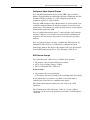
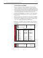
Release Notes
PowerFlex 70 Drive with Enhanced Control
Option Firmware 4.001
This release note describes major revision 4, minor revision 1 of firmware
for the PowerFlex 70 drive with Enhanced Control option only. Refer to
publication 20A-RN002 for a complete description of the changes
implemented in previous firmware revisions.
Introduction
The following information is included in the document:
For information about:
Enhancements
Corrected Anomalies
Determining Firmware Revision
Firmware Flashing
Restrictions
Compatible Revisions
Rockwell Automation Support
Product Satisfaction Return
Enhancements
See page:
1
10
14
17
20
20
20
20
Always Upload Parameters
A requirement for ADR is that a configuration download set all writable/
recallable parameters to restore ANY replacement drive with ANY existing
parameter set to what they were in the original drive. To satisfy this
requirement some parameters must always be uploaded: i.e. All the
parameters that are “preserved” through a reset to defaults as well as all
parameters with “dynamic” defaults (parameter default depends on what
another parameter is set to).
Parameter No.
41
42
43
44
45
46
47
54
55
62
63
69
70
71
72
82
91
Parameter Name
Motor NP Volts
Motor NP FLA
Motor NP Hertz
Motor NP RPM
Motor NP Power
Mtr NP Pwr Units
Motor OL Hertz
Maximum Voltage
Maximum Freq
IR Voltage Drop
Flux Current Ref
Start/Acc Boost
Run Boost
Break Voltage
Break Frequency
Maximum Speed
Speed Ref A Hi
Parameter No.
94
97
107
119
121
148
158
196
201
202
322
323
325
326
343
344
542
Parameter Name
Speed Ref B Hi
TB Man Ref Hi
Preset Speed 7
Trim Hi
Slip RPM @ FLA
Current Lmt Val
DC Brake Level
Param Access Lvl
Language
Voltage Class
Analog In 1 Hi
Analog In 1 Lo
Analog In 2 Hi
Analog In 2 Lo
Analog Out1 Hi
Analog Out1 Lo
Encdlss Vlt Comp
PowerFlex 70 Drive with Enhanced Control Option Firmware 4.001
2
Configuration Object (Copycat) Changes
In v3: The DPI Configuration Object (used by HIM copycat and Drive
Explorer Upload/Download) would upload parameter information for ALL
writable/recallable parameters. A v3.003 configuration upload (all
parameters) requires 21 x 66 byte blocks.
For Logix ADR (Automatic Device Replacement) we want to upload a reset
to defaults command followed by only the parameters that are not at their
default values. The intention is to reduce the Logix memory and the upload/
download time required by ADR.
In v4: A configuration upload requires 7 x 66 byte blocks if all parameters
and process displays are at defaults. One block will hold a minimum of 8
parameters and can hold up to 19 parameters (for consecutive parameter
numbers).
Note: Any parameter that is currently a datalink sink (P300 [Data In A1]
through P307 [Data In D2]) is excluded from a configuration upload.
Added newly defined “This Device fully complies with v2.02 specification”
bit to the DPI Configuration Object “Class Descriptor” (DPI 30.0.3)
NVS Checksum Changes
The “NVS Checksum” (DPI 1.0.11) is a CRC16 check spanning:
• All parameters that are both writable and recallable
• All (2) “Process Display Objects” (DPI 6)
• The “User Definable Text” (DPI 1.0.5)
It now excludes:
• All parameters that are data link sinks
i.e. Parameters selected by P300 [Data In A1] through P307 [Data In D2]
It is presumed that if a parameter is specified as a data link sink it is
controlled over a network via a communications adapter.
P203 [Drive Checksum] now displays the same value as the “NVS
Checksum”.
The “NVS Parameter Value Checksum” (DPI 3.0.3) is now a CRC16
calculation. It is the result of the parameter portion of the “NVS Checksum”
calculation.
PowerFlex 70 Drive with Enhanced Control Option Firmware 4.001
3
Change P549 [Flux Braking %] Default
In v3: The P549 [Flux Braking %] 175% default allows output voltage the
results in output current that exceeds current limit. The current limiter
function presumes that excess current can be corrected by reducing output
frequency thus reducing slip frequency thus reducing current. But in this
case the excess current is due to excessive voltage rather than slip
frequency. The frequency is abruptly reduced yet current remains high.
UTILITY
Diag-Motor Cntl
The P549 [Flux Braking %] default has been reduced from 175% to 125%.
549
[Flux Braking %]
E C v4
Gain adjustment for Flux Braking mode.
(Percentage of normal output voltage.)
Default:
125
166
Min/Max: 100/250
Units:
%
This parameter is only viewable when
P196 [Param Access Lvl] = 2
“Reserved.”
New Fault - F10 “Heatsink LowTemp”
In v3: F8 “Heatsink OvrTemp” is annunciated for both too high a
temperature and too low a temperature (or a broken connection to the NTC).
This has been a problem for customers in low temperature environments.
A new, maskable fault F10 “Heatsink LowTemp” is now used to annunciate
the too low temperature case.
238 [Fault Config 1]
ea
rPN
oA
Lo
cc (1
ad
)(4
)
In Los
Ph s (2)
a
Mo se
to L
De r Th oss (2)
c e
Au el Inh rm (1)
tR i
Sh st Tr bt
e
ie
Mo ar Pi s
to n
HS r Ov
e
Un Low rLd
d Te
Po erVo mp (3)
we ltag
rL e
oss
Sh
Faults
UTILITY (File E)
Enables/disables annunciation of the listed faults.
x x x x 0 x 0 0 0 1 0 0 1 x 1 0 1 = Enabled
15 14 13 12 11 10 9 8 7 6 5 4 3 2 1 0 0 = Disabled
x = Reserved
Nibble 4
Nibble 3
Nibble 2
Nibble 1
Bit #
(1)
Enhanced firmware 1.001 & later.
Factory Default Bit Values
(2)
Enhanced firmware 2.001 & later.r.
(3)
Enhanced firmware 4.001 & later.
(4)
Bit 11 enables the shear pin fault to be ignored during acceleration and
deceleration. Using Bit 11 with Bit 4 set to “0” will have no effect.
4
PowerFlex 70 Drive with Enhanced Control Option Firmware 4.001
New Fault - F112 “Power Down Csum”
In v3: On power up, data to load the structure sNVSPowerDownData is read
from the control board eeprom and checksummed. If OK,
sNVSPowerDownData is loaded otherwise all values are set to default
without any indication that the eeprom data was corrupt.
A side affect of setting sNVSPowerDownData to defaults is that it causes
P61 [Autotune] to be reset to 3 “Calculate”; changing P62 [IR Voltage
Drop], P63 [Flux Current Ref] and possibly P64 [IXo Voltage Drop]. This
has led to many cases where a drive that was working OK suddenly can't
accelerate from zero speed and it is not obvious why.
If a checksum error restoring sNVSPowerDownData from eeprom is
detected (F112), do not force P61 [Autotune] to “Calculate” of force the
drive into “Assisted Start Up.” But do force those things in response to a
DPI Manufacturing Object “Reset to Factory” command. Note: Forcing
Autotune = Calculate would overwrite “tuned” parameters, sometimes
resulting in insufficient torque to start the load.
In v4: A checksum error reading sNVSPowerDownData results in a F112
“Power Down Csum” fault.
Autotune Calculate
In v3: The online and offline default values for P62 [IR Voltage Drop], P63
[Flux Current Ref], and P542 [Encdlss Vlt Comp], are based on IrVolts and
FluxAmps values read from the power board eeprom.
If P61 [Autotune] is 3 “Calculate” (default), values for P62 [IR Voltage
Drop], P63 [Flux Current Ref], P64 [IXo Voltage Drop], and P542 [Encdlss
Vlt Comp] are calculated based on the Motor NP parameters and P53
[Motor Cntl Sel].
Thus a reset to defaults command writes the default values but they are
immediately overwritten by Autotune Calculate and a “compare to defaults”
flags them.
In v4: The offline and online values are set to what Autotune Calculate
would calculate given default Motor NP values.
The primary advantage of this change is that DriveExecutive database files
(and “offline” files based on those database files) will have “better” defaults
for P62 [IR Voltage Drop] and P63 [Flux Current Ref].
A secondary advantage is that if a drive is “reset to defaults” and then
“compared to defaults,” no differences are found.
PowerFlex 70 Drive with Enhanced Control Option Firmware 4.001
5
Improve DPI Feedback
The filtered value of speed feedback used for "DPI Feedback" is now
updated every 30mS instead of every 120mS. The filter function is the
same; the average of the last twenty 6 mS samples.
Motor NP Voltage Maximum
The original request was to increase the P41 [Motor NP Volts] online
maximum so that 415V could be entered into a “400V” drive. (With v3
software, P41 [Motor NP Volts] is limited to P27 [Rated Volts].)
With v4: The P041 [Motor NP Volts] online maximum is now the drives
high voltage rating:
• 208/240 => 240.0V
• 400/480 => 480.0V
• 600/600 => 600.0V
Now you can enter 415V and 50Hz into a 400V drive and get the correct V/
Hz ratio.
Note: The P54 [Maximum Voltage] online maximum is still rated volts and
“VoltageLimit()” software limits commanded voltage to that value or to
what it calculates is the maximum possible for a given bus voltage (and
P523 [Bus Utilization]).
Note: The online limit for P71 [Break Voltage] and P64 [IXo Voltage Drop]
is the same as P41 [Motor NP Volts], for P62 [IR Voltage Drop] and P542
[Encdlss Vlt Comp] it’s ½ that and for P69 [Start/Acc Boost] and P70 [Run
Boost] it’s ¼ that. These limits also increase in the low voltage case.
Thermal Manager
The drive thermal manager has been improved to reduce nuisance F9 IGBT
over temperature faults. The thermal manager improvements better control
the peak IGBT junction temperatures during a shock load or at non-default
PWM frequencies to help extend the life of the drive.
PowerFlex 70 Drive with Enhanced Control Option Firmware 4.001
Process PI Reference and Feedback
The Process PI function is enhanced to support “Automotive Chain
Conveyor” applications. A “follower” drive uses its process pi block to
compare its torque load to the torque load on a neighboring “master” drive
and to trim its speed command to achieve load sharing. In FVC control P24
[Commanded Torque] is the usual measure of load torque. In other control
modes P15 [Torque Estimate] or P4 [Torque Current] may be used.
Selections 31 “CommandedTrq”, 32 “Torque Est”, and 33 “Torque Amps”
have been added to P128 [PI Feedback Select] to support “Automotive
Chain Conveyor.”
The selected torque load signal from the master drive may be transmitted
through an analog output and received by an analog input at the follower
drive. Or it may be datalink'ed from the master drive via a PLC or via the
“peer to peer” function supported by 20-COMM adapters.
Selections 25 “Scale Block1” and 26 “Scale Block2” have been added to
P126 [PI Reference Select] specifically to support a datalink to the master
drive torque.
126 [PI Reference Sel]
Default:
Selects the source of the PI reference.
Process PI
(1)
SPEED COMMAND (File C)
6
Options
0
1
2
3-7
8
9
10
11-17
18-20
21
22
23-24
25
26
27-29
30
31
32
33
0
Options:
“PI Setpoint”
See Table
124
thru
138
Enhanced Control Drives Only.
“Setpoint”
“Analog In 1”
“Analog In 2”
“Reserved”
“Encoder”
“MOP Level”
“Master Ref”
“Preset Spd1-7”
“DPI Port 1-3”
“Reserved”
“DPI Port 5”
“Reserved”
“Scale Block1”
“Scale Block2”
“Reserved”
“HighRes Ref” (1)
“CommandedTrq” (2)
“Torque Est” (2)
“Torque Amps” (2)
P462 [PI Feedback Hi]
+100
P322 [Analog In1 Hi]
P325 [Analog In2 Hi]
P463 [PI Feedback Lo]
-100
P323 [Analog In1 Lo]
P326 [Analog In2 Lo]
+P55 [Maximum Freq]
+P55 [Maximum Freq]
+P55 [Maximum Freq]
+P55 [Maximum Freq]
+32767
-P55 [Maximum Freq]
-P55 [Maximum Freq]
-P55 [Maximum Freq]
-P55 [Maximum Freq]
-32676
+32767
-32676
P477 [Scale1 In Hi]
P483 [Scale2 In Hi]
P478 [Scale1 In Lo]
P484 [Scale2 In Lo]
+32767 x 216
P436 [Pos Torque Limit]
P436 [Pos Torque Limit]
+P28 [Rated Amps]
-32767 x 216
P437 [Neg Torque Limit]
P437 [Neg Torque Limit]
-P28 [Rated Amps]
128 [PI Feedback Sel]
Selects the source of the PI reference.
(1) Enhanced Control Drives Only.
Default:
Options:
2
“Analog In 2”
124
thru
See
138
P126 [PI Reference
Sel]
PowerFlex 70 Drive with Enhanced Control Option Firmware 4.001
7
Added Scaled Blocks Parameters
To support “Automotive Chain Conveyor” applications we need to
“datalink” the master torque reference to the follower drive. We need a
parameter in the follower drive that is WRITABLE and selectable by P126
[PI Reference Sel].
To provide flexible limiting, scaling, and offset, part of the “scaled blocks”
function of the PF700VC is adapted to the PF70EC.
Note: The VC supports “parameter linking” but the EC doesn’t. The
“ScaleX Out” parameters in the VC are only useful with parameter linking.
Note: All VC parameters are 32 bits. Most EC parameters are 16 bits and
we want these new parameters to be 16 bit signed in the EC.
Note: When using datalinks, values that are outside the min and max of the
sink parameter are ignored. For Example: If P127 [PI Setpoint] was
datalink’ed to the master drive torque and the torque suddenly stepped from
0.00% to 100.01%, [PI Setpoint] would stay at 0.00%. Using [ScaleX In
Value] (accepts any 16 bit value) avoids that problem.
476
Scaled Blocks
UTILITY (File E)
482
477
483
478
484
E C v4
[Scale1 In Value]
Default:
0.0
[Scale2 In Value]
Min/Max: -3276.8/+3276.7
E C v4
0.1
Displays the value of the signal being sent Units:
to [ScaleX In Value] using a datalink.
E C v4
Default:
[Scale1 In Hi]
[Scale2 In Hi]
E C v4
Scales the upper value of [ScaleX In
Value].
E C v4
[Scale1 In Lo]
Default:
[Scale2 In Lo]
E C v4
Scales the lower value of [ScaleX In
Value].
0.0
Min/Max: -3276.8/+3276.7
Units:
0.1
0.0
Min/Max: -3276.8/+3276.7
Units:
0.1
90
93
117
126
127
427
91
94
119
428
460
462
92
95
120
429
461
463
Other Scaled Blocks Uses
The necessary selections to use scaled block functionality have also been
added to:
•
•
•
•
P90 [Speed Ref A Sel]
P93 [Speed Ref B Sel]
P213 [Speed Ref Source]
P427 [Torque Ref A Sel]
25 “Scale Block1” and 26 “Scale Block2”
25 “Scale Block1” and 26 “Scale Block2”
26 “Scale Block1” and 27 “Scale Block2”
25 “Scale Block1” and 26 “Scale Block2”
Tip: With parameters defaulted; set P447 [Scale1 In Hi] = 1800.0 and P90
[Speed Ref A Sel] = 25 “Scale Block1”. Then a speed command can be
entered in P476 [Scale1 In Value] in 0.1 RPM units.
Tip: We expect that using a scaled block and speed trim together will be an
optimal solution to many application problems.
PowerFlex 70 Drive with Enhanced Control Option Firmware 4.001
Add “Speed Fdbk” to [Digital OutX Sel]
Added 61 “Speed Fdbk” to P380 [Digital Out1 Sel] and P384 [Digital Out2
Sel]. The value of P25 [Speed Feedback] is compared against P381 [Dig
Out1 Level] or P385 [Dig Out3 Level] to set the relay state.
380 [Digital Out1 Sel]
384 [Digital Out2 Sel]
Default:
Selects the drive status that will energize Options:
a (CRx) output relay.
Digital Outputs
(1)
INPUTS & OUTPUTS (File J)
8
Any relay programmed as Fault or
Alarm will energize (pick up) when
power is applied to drive and
deenergize (drop out) when a fault or
alarm exists. Relays selected for other
functions will energize only when that
condition exists and will deenergize
when condition is removed.
(2)
Activation level is defined in [Dig Outx
Level] below.
(3) Enhanced Control Drives Only.
(4) Enhanced Firmware V3.002 and later.
(5)
Enhanced Firmware V4.001 and later.
1
4
“Fault”
“Run”
1
2
3
4
5
6
7
8
9
10
11
12
13
14
15
16
17
18
19
20
21
22
23
24
25
26
27
28
29
30
31-57
58
59
60
61
“Fault”(1)
“Alarm”(1)
“Ready”
“Run”
“Forward Run”
“Reverse Run”
“Auto Restart”
“Powerup Run”
“At Speed”
“At Freq”(2)
“At Current”(2)
“At Torque”(2)
“At Temp”(2)
“At Bus Volts”(2)
“At PI Error”(2)
“DC Braking”
“Curr Limit”
“Economize”
“Motor Overld”
“Power Loss”
“Input 1 Link”
“Input 2 Link”
“Input 3 Link”
“Input 4 Link”
“Input 5 Link”
“Input 6 Link”
“PI Enabled”(3)
“PI Hold”(3)
“Drive Overld”(3)
“Param Cntl”(3)
“Reserved”
“Manual Mode”(4)
“Fast Braking”(4)
“Reserved”
“Speed Fdbk”(2)(5)
381
385
382
383
002
001
003
004
218
012
137
157
147
053
048
184
PowerFlex 70 Drive with Enhanced Control Option Firmware 4.001
9
New Power Loss Mode
If P184 [Power Loss Mode] = 5 “Decel 2 Stop”:
• If P12 [DC Bus Voltage] drops to = (P13 [DC Bus Memory] - 120), set
P211 [Drive Alarm 1] Bit 2 “Power Loss” = 1 and P215 [Last Stop
Source] = 0 “Pwr Removed.”
• The logic sequencing treats this similar to a “ramp to stop” except it
forces the ramp to use P143 [Decel Time 2] with no s-curve to set the
ramp and any P159 [DC Brake Time] is ignored.
• P143 [Decel Time 2] must be set short enough to keep the drive
renenerating power from the load for the duration of the stop.
• If P12 [DC Bus Voltage] drops to = (P13 [DC Bus Memory] - 180), the
drive switches to a coast stop and the precharge relay opens.
• If P161/162 [Bus Reg Mode X] is 1 “Adjust Freq,” the actual decel time
may be increased to limit P12 [DC Bus Voltage].
• If P238 [Fault Config 1] Bit 0 “Power Loss” is set (NOT the default), the
drive will fault after P185 [Power Loss Time].
• P211 [Drive Alarm 1] Bit 2 “Power Loss” is cleared once BOTH the
drive is stopped AND
• P12 [DC Bus Voltage] = (P13 [DC Bus Memory] - 60). The drive can
then accept a re-start command.
• If Power Loss Level is active, it sets the P12 [DC Bus Voltage] setpoints.
For P184 [Power Loss Mode] 0…4, if power is restored before low of
control board power and run is maintained, the response to restored power is
to do a flying start and return to the commanded speed.
This new P184 [Power Loss Mode] is intended for cases where a power loss
causes a process disruption and the desired drive response is to stop as
quickly as possible and not to restart until commanded (and power is
restored).
P143 [Decel Time 2] is automatically selected to allow for cases where the
“normal operation” decel is not fast enough to keep the drive regenerating
power all the way to zero speed. If P143 [Decel Time 2] is not short enough
to keep the bus up, the drive switches to a coast stop.
Note: This is essentially a ramp to stop, while active it over-rides P155
[Stop/Brk Mode A].
Note: If P184 [Power Loss Mode] is set to 3 “Reserved” it changes to 0
“Coast” and if set to 4 “Reserved” it changes to 1 “Decel.”
10
PowerFlex 70 Drive with Enhanced Control Option Firmware 4.001
Power Loss
DYNAMIC CONTROL (File D)
184 [Power Loss Mode]
013
“Coast”
Default: 0
185
Sets the reaction to a loss of input power. Options: 0
“Coast”
Power loss is recognized when:
“Decel”
1
“Continue” E C
2
• DC bus voltage is ≤ 73% of [DC Bus
“Reserved”
3
Memory] and [Power Loss Mode] is
“Reserved”
4
set to “Coast”.
“Decel 2 Stop” E C v4
5
• DC bus voltage is ≤ 82% of [DC Bus
Memory] and [Power Loss Mode] is
set to “Decel”.
“Coast” = Disable drive and allow the motor to coast.
“Decel” = Decelerate the motor at a rate which will regulate the DC Bus until the
load’s Kinetic Enrgy can no longer power the drive.
“Continue” = Allow the drive to power the motor down to 50% of the nominal DC
Bus voltage.
Refer to the PowerFlex 70EC/700VC Reference Manual, publication
PFLEX-RM004 for additional information.
!
Corrected Anomalies
ATTENTION: To guard against drive damage; in “Continue” mode
a minimum line impedance must be provided to limit inrush current
when the power line recovers. The input impedance should be
equal or greater than the equivalent of a 5% transformer with a VA
rating 6 times the drive’s input VA rating.
No Flying Start with Diagnostics Disabled
In v3: The Drive will not execute a Flying Start for P56 [Compensation] Bit
3 “Xsistor Diag” = 0 “Disabled” (i.e. Power Stage Diagnostics disabled).
This has been corrected in v4.
Note: Diagnostics are enabled by default. A sine wave filter may require
disabling diagnostics.
Hardware Fault with Process PI and DC or Fast Brake
In v3: The drive can overcurrent or overvoltage trip when initiating DC
Brake or Fast Brake using SVC or V/Hz control with Process PI enabled.
Process PI code that adjusts frequency at a transition to a stop was causing a
frequency step when transitioning to flux down. This has been corrected in
v4.
Note: There is a simple work around for earlier code, set P124 [PI
Configuration] Bit 6 “Stop Mode” = 1 “Enabled”.
Error Reading P1 [Output Freq] via SCANport
In v3: There is an error in the Formula Data sent for P1 [Output Freq] when
read through SCANport (but not DPI). This caused Drive Executive and
RSNetworx DeviceNet to display a grossly incorrect value for Output Freq
when connected to the drive via a SCANport adapter. This has been
corrected in v4.
SCANport write “parameter data value” commands were NOT triggering an
sActiveSet save to non-volatile storage. This has been fixed. Note: This only
affects systems using SCANport HIMs and/or communications adapters
(almost none), systems using DPI HIMs and adapters are not affected.
PowerFlex 70 Drive with Enhanced Control Option Firmware 4.001
11
Fault Queue Data Not Saved
A small but important error was introduced in v3.002: “Fault Queue” data is
not being stored in nvs. The queue itself works correctly but on power up it
is loaded with what ever happened to be in eeprom. This has been corrected
in v4.
Note: This problem only affected the “Fault Queue”. The fault parameters
P243 [Fault 1 Code] through P250 [Fault 4 Time] were/are saved and
restored correctly.
Maximum PWM Frequency
Frame E drives should limit P151 [PWM Frequency] to 8kHz instead of
12kHz. (The maximum is programmed into the power board eeprom.)
Online tools (HIM, Drive Explorer) limit P151 [PWM Frequency] to the
programmed maximum.
Offline tools (Drive Executive, RSNetworx) SHOULD allow setting P151
[PWM Frequency] to 12kHz (the offline maximum) BUT the drive should
internally limit the active pwm frequency to the online maximum. This has
been fixed.
NOTE: The diagnostic parameter P4 [Active PWM Freq] shows the
internally limited value.
Re-Calculate Flux Up Time
A change to P45 [Motor NP Power] or P63 [Flux Current Ref] now
re-calculates P58 [Flux Up Time] if P57 [Flux Up Mode] = 1 “Automatic.”
Note: A customer programmed automatic flux up time, autotuned the drive,
and saved the parameters. After a power cycle the customer noted that Flux
Up Time had changed. This was traced to not re-calculating time after
autotune changed flux current.
Fast Brake Overvoltage Trip
The drive could trip on F5 OverVoltage if executing a Fast Brake stop with
P161 [Bus Reg Mode A] = 0 “Disabled.” This has been fixed.
12
PowerFlex 70 Drive with Enhanced Control Option Firmware 4.001
Synchronous Motor Operation
Problems using the EC with synchronous motors have been fixed:
Problem 1: Program the drive for a ramp stop with dc braking (or ramp to
hold) and zero speed command. As the drive is started and stopped, a PM
synchronous motor will “jump” 90° (electrical).
Brake current was always applied in the D axis, correct for induction motors
but not for synchronous motors. Now, for P40 [Motor Type] = 1 “Synchr
Reluc” or 2 “Synchr PM”, brake current is applied in the +Q axis.
Problem 2: Command 0.1 Hz, start the drive, then reverse the direction. At
each reverse, the shaft of a PM synchronous motor "jumps" by 180°
(electrical).
Previously all voltage was applied in the +Q axis for frequency = 0, and in
the -Q axis for frequency < 0. Now, for P40 [Motor Type] = 1 “Synchr
Reluc” or 2 “Synchr PM”, all voltage is applied in the +Q axis.
Note: This would result in the polarities of both P4 [Torque Current] and P5
[Flux Current] to be the opposite what you'd get with an induction motor in
reverse rotation. The polarities of displayed have been “corrected” to match
the “expected” polarity.
RSNetWorx DeviceNet EDS File Generator
For v3: The RSNetWorx for DeviceNet EDS Wizard “Create and EDS File”
function fails. At place in the File Group Param structure where the
PF700VC locates the group “Scaled Blocks,” the PF70EC has a group
labeled “Reserved” with zero parameters. Apparently RSNetWorx can not
deal with a group that has zero parameters.
Adding the new scaled blocks parameters to that block fixes the problem.
PowerFlex 70 Drive with Enhanced Control Option Firmware 4.001
Appendix
New Parameters
File
Utility
Utility
Utility
Utility
Utility
Utility
Group
Scaled Blocks
Scaled Blocks
Scaled Blocks
Scaled Blocks
Scaled Blocks
Scaled Blocks
Parameter
P476 [Scale1 In Value]
P477 [Scale1 In Hi]
P478 [Scale1 In Lo]
P482 [Scale2 In Value]
P483 [Scale2 In Hi]
P484 [Scale2 In Lo]
Group
Faults
Parameter
P238 [Fault Config 1]
New Bits
File
Utility
Bit
2 “HS Low Temp”
New Enums
File
Group
Parameter
Speed Command Speed References P90 [Speed Ref A Sel]
P93 [Speed Ref B Sel]
Speed Trim
P117 [Trim In Sel]
Process PI
P126 [PI Reference Sel]
P128 [PI Feedback Sel]
Dynamic Control
Utility
Power Loss
Diagnostics
P184 [Power Loss Mode]
P213 [Speed Ref Source]
Inputs & Outputs
Digital Outputs
Motor Control
Torq Attributes
P380 [Digital Out1 Sel]
P384 [Digital Out2 Sel]
P427 [Torque Ref A Sel]
New Faults
No.
10
112
Name
Heatsink LowTemp
Power Down Csum
Bit
25 “Scale Block1”
26 “Scale Block2”
25 “Scale Block1”
26 “Scale Block2”
25 “Scale Block1”
26 “Scale Block2”
25 “Scale Block1”
26 “Scale Block2”
31 “CommandedTrq”
32 “Torque Est”
33 “Torque Amps”
25 “Scale Block1”
26 “Scale Block2”
31 “CommandedTrq”
32 “Torque Est”
33 “Torque Amps”
5 “Decel 2 Stop”
26 “Scale Block1”
27 “Scale Block2”
61 “Speed Fdbk”
61 “Speed Fdbk”
25 “Scale Block1”
26 “Scale Block2”
13
14
PowerFlex 70 Drive with Enhanced Control Option Firmware 4.001
Determining Firmware
Revision
This section describes procedures to determine the firmware revision of
your PowerFlex 70 drive with Enhanced Control option.
Using the LCD HIM (20-HIM-**)
Step
1. In the main menu, press the Up Arrow or
Down Arrow to scroll to Device Select.
Key(s)
Example Screens
OR
2. Press Enter to enter your selection.
3. Press the Up Arrow or Down Arrow to
scroll to the PowerFlex 70 EC drive.
OR
4. Press Enter to select the drive. The main
menu for the drive will appear.
5. Press the Up Arrow or Down Arrow to
scroll to Diagnostics.
6. Press Enter to enter your selection.
7. Press the Up Arrow or Down Arrow to
scroll to Device Version.
8. Press Enter to display the Product Data
screen.
9. Press Enter again to display the adapter’s
firmware version.
OR
F-> Stopped
Auto
0.00
Hz
Main Menu:
Diagnostics
Parameter
Device Select
F-> Stopped
Auto
0.00
Hz
Main Menu:
Diagnostics
Parameter
Device Select
F-> Stopped
Auto
Pt0: PowerFlex 70 EC
Next
Prev
PowerFlex 70 EC
240V 4.2A
FW: 3.003
HW: A Date: 11/07/2000
PowerFlex 70 Drive with Enhanced Control Option Firmware 4.001
15
Using DriveExplorer Lite/Full
1. Launch DriveExplorer and go online (via 1203-USB or 1203-SSS
converter) with the connected drive.
2. In the DriveExplorer treeview, click on the PowerFlex 70 EC drive as
shown in Figure 1.
3. Click the information icon to display the drive’s Properties screen.
4. The “Revision:” field shows the present revision (for example, 3.003) of
the drive firmware.
TIP: When clicking on the drive using version 5.01 or higher
DriveExplorer Lite/Full, the drive firmware revision is also shown in the
right pane of the DriveExplorer window.
Figure 1 Information Icon in DriveExplorer Window
Step 3
Step 2
Step 4
16
PowerFlex 70 Drive with Enhanced Control Option Firmware 4.001
Using DriveExecutive
1. Launch DriveExecutive and go online with the connected drive.
2. In the DriveExecutive treeview, click on the PowerFlex 70 EC drive as
shown in Figure 2.
3. Click the information icon to display the drive’s Properties screen.
4. The “Revision:” field shows the present revision (for example, 3.003) of
the drive firmware.
Figure 2 Information Icon in DriveExecutive Window
Step 3
Step 2
Step 4
PowerFlex 70 Drive with Enhanced Control Option Firmware 4.001
Firmware Flashing
17
This section describes procedures to flash upgrade your drive firmware.
Flash kits for drives and communications adapters are provided on the
Allen-Bradley Web Updates site located at:
http://www.ab.com/support/abdrives/webupdate
!
ATTENTION: Risk of permanent equipment damage exists. Once a flash
update has been started, do not remove power from the drive until after the
download has completed and the STS status indicator on the drive becomes
FLASHING GREEN. If power is removed before this occurs, the drive
may be permanently damaged. A drive that has been damaged in this way
cannot be repaired.
Installing the Flash Kit
1. Install the flash kit utility from the Allen-Bradley Web Updates site for
the PowerFlex 70 EC drive. (This also automatically installs the latest
version of the ControlFLASH utility on your computer.)
2. You are now ready to use DriveExplorer, DriveExecutive,
ControlFLASH or HyperTerminal to update the drive. Follow the
instructions in the appropriate section below.
Using DriveExplorer Lite/Full
1. With the Flash Kit installed (see Installing the Flash Kit), launch
DriveExplorer and go online (via a 1203-USB or 1203-SSS converter)
with the drive.
2. In the DriveExplorer treeview, click on the PowerFlex 70 EC drive. Then
click the information icon as shown in Figure 1 to display the drive’s
Properties screen.
3. On the PowerFlex 70 EC Properties screen, click the Details tab.
Important: This update may cause the drive parameters to revert to their
default values. You may want to save your configuration
using DriveExplorer or the HIM CopyCat feature before
upgrading.
4. To start the flash update, click the Flash Update… button. Follow the
additional steps and screen prompts until the flash update procedure
completes and displays the new firmware revision (v4.001).
Using DriveExecutive
1. With the Flash Kit installed (see Installing the Flash Kit), launch
DriveExecutive and go online with the connected drive.
18
PowerFlex 70 Drive with Enhanced Control Option Firmware 4.001
2. In the DriveExecutive treeview, click on the PowerFlex 70 EC drive.
Then click the information icon as shown in Figure 2 to display the
drive’s Properties screen.
3. On the PowerFlex 70 EC Properties screen, click the Component Details
tab.
Important: This update may cause the drive parameters to revert to their
default values. You may want to save your configuration
using DriveExecutive or the HIM CopyCat feature before
upgrading.
4. To start the flash update, click the Flash Update button. Follow the
additional steps and screen prompts until the flash update procedure
completes and displays the new firmware revision (v4.001).
Using ControlFLASH
1. With the Flash Kit installed (see Installing the Flash Kit on page 17),
launch ControlFLASH by selecting Start > (All) Programs > Flash
Programming Tools > ControlFLASH.
2. On the ControlFLASH Welcome screen, click Next >.
3. Choose the PowerFlex 70 EC from the list and click Next >.
Important: This update may cause the drive parameters to revert to their
default values. You may want to save your configuration
using the HIM CopyCat feature, DriveExplorer or
DriveExecutive before upgrading.
4. Expand the treeview for the communication path you are using, and
select the drive icon that represents the drive you are updating. Then
click OK.
5. With the Multiple Assemblies Found window displayed, select “Port 0 PowerFlex 70 EC” from the list and click OK.
6. With the Firmware Revision window displayed, select “4.001.xx” from
the list of available updates and click Next >. Follow the remaining steps
and screen prompts until the flash procedure completes and displays the
new firmware revision (v4.001).
Using HyperTerminal
1. With the Flash Kit installed (see Installing the Flash Kit on page 17),
launch HyperTerminal and go online (via 1203-USB or 1203-SSS
converter) with the connected drive.
2. Press the Enter key until the main menu (Figure 3) appears.
PowerFlex 70 Drive with Enhanced Control Option Firmware 4.001
19
Figure 3 Main Menu
Main Menu - Enter Number for Selection
1> Display Setup Parameters
2> Display Event Queue
3> Flash Upgrade
3. In the main menu, press 3 to flash upgrade. Then press the number key
that corresponds to the “PowerFlex 70 EC” in the list, and press Y (for
Yes) to update the flash code. The terminal program will start
displaying the letter “C”. This signals the XMODEM protocol that the
download may proceed. You then have one minute to start the transfer.
Press CTRL-X to cancel a started update.
!
ATTENTION: Risk of injury or equipment damage exists. When you
perform a flash update, the drive will fault if it is receiving control I/O from
the adapter. Verify that the drive has stopped safely or is receiving control
I/O from an alternate source before beginning a flash update.
4. Select Transfer > Send File to display the Send File screen (Figure 4).
5. Click Browse and navigate to the flash file located in:
C:\ Program Files\ControlFLASH\0001\0078\0032
Figure 4 Send File Screen
6. In the Select File to Send window list, double-click on the
“PF70EC_App_4_001_31.bin” file. This file name now appears in the
Filename box in the Send File screen.
7. In the Protocol box, select “Xmodem.”
8. Click Send. A dialog box appears and reports the progress of the
update. When it is complete, the message “Flash Complete” appears.
HyperTerminal also checks the new firmware in the drive and resets the
drive.
Important: Keep the device powered for 15 seconds after the operation
has completed or until the drive STS status indicator starts
flashing green.
9. Press the Enter key to return to the main menu.
Restrictions
No restrictions apply to this revision of firmware.
Compatible Revisions
To use this revision of firmware, update your system tools as follows:
Update this:
DriveExplorer Lite/Full
DriveExecutive
LCD HIM
RSLinx Classic
Rockwell Automation
Support
To this version or later:
4.01
3.01
all versions compatible
2.43
Rockwell Automation provides technical information on the web to assist
you in using our products. At http://support.rockwellautomation.com, you
can find technical manuals, a knowledge base of Frequently Asked
Questions (FAQs), technical and application notes, sample code and links to
software service packs, and a MySupport feature that you can customize to
make the best use of these tools.
Rockwell Automation also provides complimentary phone support for
drives, communication adapters, and peripherals. If you experience a
problem with the adapter, please review the information in its User Manual.
For further help in getting your adapter operational, contact a Customer
Support representative:
United States
Outside United States
(1) 262.512.8176
Monday – Friday, 7am – 6pm CST
Please contact your local Rockwell Automation
representative for any technical support issues.
For an additional level of technical phone support for installation,
configuration and troubleshooting, we offer TechConnect Support
programs. For more information, contact your local distributor or Rockwell
Automation representative, or visit http://support.rockwellautomation.com.
Product Satisfaction Return Rockwell Automation tests all products to ensure that they are fully
operational when shipped from the manufacturing facility. However, if your
product is not functioning and needs to be returned:
United States
Outside United States
Contact your distributor. You must provide a Customer
Support case number (see phone number above to obtain
one) to your distributor to complete the return process.
Please contact your local Rockwell Automation
representative for return procedure.
U.S. Allen-Bradley Drives Technical Support - Tel: (1) 262.512.8176, Fax: (1) 262.512.2222, Email: [email protected], Online: www.ab.com/support/abdrives
www.rockwellautomation.com
Power, Control and Information Solutions Headquarters
Americas: Rockwell Automation, 1201 South Second Street, Milwaukee, WI 53204 USA,Tel: (1) 414.382.2000, Fax: (1) 414.382.4444
Europe/Middle East/Africa: Rockwell Automation, Vorstlaan/Boulevard du Souverain 36, 1170 Brussels, Belgium,Tel: (32) 2 663 0600, Fax: (32) 2 663 0640
Asia Pacific: Rockwell Automation, Level 14, Core F, Cyberport 3, 100 Cyberport Road, Hong Kong,Tel: (852) 2887 4788, Fax: (852) 2508 1846
Publication 20A-RN003A-EN-P – April, 2009
Copyright © 2009 Rockwell Automation, Inc. All rights reserved. Printed in USA.