1
Worldwide Sumitomo Network
U.S.A.
Sumitomo Machinery Corporation of America (SMA)
4200 Holland Blvd. Chesapeake,VA 23323,U.S.A.
Tel:+1-757-485-3355
Fax:+1-757-485-7490
Germany
Sumitomo (SHI) Cyclo Drive Germany GmbH (SCG)
Cyclostraße 92, 85229 Markt Indersdorf, Germany
Tel:+49-8136-66-0
Fax:+49-8136-5771
Argentina
SM Cyclo de Argentina S.A. (SMAR)
Ing. Delpini, 2236Area de Promocion el Triangulo,
Partido Malvinas Argentinas Grand Bourg,
Buenos Aires, Argentina - B1615KGB
Tel:+54-3327-45-4095
Fax:+54-3327-45-4099
Austria
Sumitomo (SHI) Cyclo Drive Germany GmbH (SCG)
SCG Branch Austria Office
Gruentalerstraße 30A, 4020 Linz, Austria
Tel:+43-732-330958
Fax:+43-732-331978
Brazil
SM Cyclo Redutores do Brasil, Com.Ltda. (SMBR)
Av. Marquês de São Vicente, 587 - Barra Funda,
São Paulo - SP, 01139-001, Brasil
Tel:+55-11-5585-3600
Fax:+55-11-5585-3600
Chile
SM Cyclo de Chile, Ltda. (SMCH)
San Pablo 3507, Quinta Normal
Santiago, Chile
Tel:+56-2-892-7000
Fax:+56-2-892-7001
Mexico
SM Cyclo de Mexico, S.A. de C.V. (SMME)
Av. Desarrollo No. 541, Parque Industrial Finsa
Guadalaupe
Guadalaupe, Nuevo Leon, Mexico, CP67114
Tel:+52-81-8144-5130
Fax:+52-81-8369-3699
Canada
SM Cyclo of Canada, Ltd. (SMC)
1453 Cornwall Road,Oakville,
Canada ON L6J 7T5
Tel:+1-905-469-1050
Fax:+1-905-469-1055
Guatemala
SM Cyclo de Guatemala Ensambladora, Ltda. (SMGT)
Parque Industrial Unisur, 0 Calle B 19-50 Zona 3,
Bodega D-1 Delta Bárcenas en Villa Nueva, Guatemala
Tel:+502-6648-0500
Fax:+502-6631-9171
Colombia
SM Cyclo Colombia, S.A.S.
Carrera 11, No.93A-53, Office 203, Bogotá, Colombia
Tel:+57-1-3000673
Belgium
Sumitomo (SHI) Cyclo Drive Germany GmbH (SCG)
SCG Branch Benelux Office
Heikneuterlaan 23, 3010 Kessel-Lo, Leuven, Belgium
Tel:+32-16-60-83-11
Fax:+32-16-60-16-39
France
SM-Cyclo France SAS (SMFR)
8 Avenue Christian Doppler, 77700 Serris, France
Tel:+33-164171717
Fax:+33-164171718
Italy
SM-Cyclo Italy Srl (SMIT)
Via dell' Artigianato 23, 20010 Cornaredo (MI), Italy
Tel:+39-293-481101
Fax:+39-293-481103
Turkey
SM Cyclo Turkey Güç Aktarım Sis. Tic. Ltd. Sti. (SMTR)
Büyükdere Çayırbaşı Cd. Dede Yusuf Sk. No:11,
34453 Sarıyer Istanbul, Turkey
Tel:+90-216-384-4482
Fax:+90-216-384-4482
Spain
SM-Cyclo Iberia, S.L.U. (SMIB)
C/Landabarri No. 3, 6˚B, 48940 Leioa, Vizcaya, Spain
Tel:+34-9448-05389
Fax:+34-9448-01550
Sweden
SM-Cyclo Scandinavia AB (SMSC)
Industrigatan 21B, 234 35 Lomma, Sweden
Tel:+46-40220030
China
Sumitomo (SHI) Cyclo Drive China, Ltd. (SCT)
11F,SMEG Plaza, No.1386 Hongqiao Road,
Changning District, Shanghai. (P.C.200336)
Tel:+86-21-3462-7877
Fax:+86-21-3462-7922
Hong Kong
SM-Cyclo of Hong Kong Co.,Ltd. (SMHK)
Rm 1301, CEO Tower, 77 Wing Hong Street,
Cheung Sha Wan, Kowloon, Hong Kong
Tel:+852-2460-1881
Fax:+852-2460-1882
Korea
Sumitomo (SHI) Cyclo Drive Korea, Ltd. (SCK)
Royal Bldg. 9F Rm.913, 5 Danju-Dong, Chongro-Ku,
Seoul, Korea 110-721
Tel:+82-2-730-0151
Fax:+82-2-730-0156
Taiwan
Tatung SM-Cyclo Co., Ltd. (TSC)
22 Chungshan N. Road 3rd., Sec. Taipei, Taiwan 104,
R.O.C.
Tel:+886-2-2595-7275
Fax:+886-2-2595-5594
Singapore
Sumitomo (SHI) Cyclo Drive Asia Pacific Pte. Ltd. (SCA)
15 Kwong Min Road, Singapore 628718
Tel:+65-6591-7800
Fax:+65-6863-4238
Philippines
Sumitomo (SHI) Cyclo Drive Asia Pacific Pte. Ltd. (SCA)
Philippines Branch Office
B2B Granville Industrial Complex, Carmona,
Cavite, Philippines
Tel:+63-2-584-4921
Tel:+63-46-430-3591
Tel:+63-46-482-0580
Tel:+63-46-482-0581
Fax:+63-2-584-4922
Vietnam
Sumitomo (SHI) Cyclo Drive Asia Pacific Pte. Ltd. (SCA)
SCA Representative Office in Ho Chi Minh
10th Floor, ACB Tower. 444A-446 Cach Mang
Thang Tam Street, Ward 11, Dist.3, HCMC. Vietnam
Tel:+84-8-39-930-021
Fax:+84-8-39-930-061
Malaysia
SM-Cyclo of Malaysia Sdn. Bhd. (SMMA)
No.7C, Jalan Anggerik Mokara 31/56, Kota Kemuning,
Seksyen 31, 40460 Shah Alam, Selangor D.E., Malaysia
Tel:+60-3-51210455
Fax:+60-3-51210578
Indonesia
PT. SM-Cyclo Indonesia
Kawasan Industri Lippo Cikarang
Jalan Sungkai Blok F 25 No.09 K Delta Silicon 3
Lippo Cikarang, Bekasi, Indonesia
Tel:+62-21-5785-3181
Fax:+62-21-5795-1210
Thailand
SM-Cyclo (Thailand) Co., Ltd.
195 Empire Tower, 21st Fl., Unit 2103-4, South
Sathorn Rd.,
Yannawa Sathorn, Bangkok 10120, Thailand
Tel:+66-2-670-0998
Fax:+66-2-670-0999
Australia
Sumitomo (SHI) Hansen Australia Pty. Ltd. (SHAU)
181 Power Street Glendenning NSW 2761, Australia
Tel:+61-2-9208-3000
Fax:+61-2-9208-3050
HF-430α Series
High-performance Inverter
5.5∼55kW/200V Class
5.5∼55kW/400V Class
Operating and Maintenance Manual
India
Sumi-Cyclo Drive India Pvt. Ltd. (SMIN)
Survey No.130, Hissa No.02, Jeevan Nagar,
Off Mumbai-Bangalore bypass, Tathawade,
Pune-411 033, India
Tel:+91-20-6674-2900
Fax:+91-20-6674-2901
Japan
Sumitomo Heavy Industries, Ltd.
ThinkPark Tower, 1-1 Osaki 2-chome,
Shinagawa-ku, Tokyo 141-6025, Japan
Tel:+81-3-6737-2511
Fax:+81-3-6866-5160
United Kingdom
SM-Cyclo UK Ltd. (SMUK)
Unit 29, Bergen Way, Sutton Fields Industrial Estate,
Kingston upon Hull, HU7 0YQ, East Yorkshire,
United Kingdom
Tel:+44-1482-790340
Fax:+44-1482-790321
NOTICE
Specifications, dimensions, and other items are subject to change without prior notice.
1. Make sure that this operating and maintenence manual is
delivered to the end user of inverter unit.
2. Read this manual before installing or operating the inverter
unit, and store it in a safe place for reference.
E10A
Power Transmission & Controls Group
Headquarter ThinkPark Tower, 1-1 Osaki 2-chome, Shinagawa-ku, Tokyo 141-6025, Japan
No.DM2401E-1.1
Printed 2014.09
Manual DM2401E-1
!
"#$% & '
㸟 !
(
& '
㸟 "#$% (
㸟
"#$%
)
* *+
㸟 ,
-
.
,
㸟 / /%
-
/ .
%
-
/ %
-
(
/ 0
1
2
%
-
/ %
-
(
/ %
-
(
/ .
%
-
(
/ /
+
+
+
%
-
/ $
).
(
.
㸟 / %
-
-
/ "
-
)%
-
-
/ -
%
-
-
/ 0
%
-
-
(
/ .
%
㸟 / -
"
%
-
(
/ .
/
%
-
/ .
"
1#32%
-
(
/ .
."1040 2%
-
/ "
/--
%
-
/ #
/--
12%
-
/ .
/ $
) %
-
/ 54
%
-
-(
/ 5
/
$
%
-
-(
㸟 / -
%
-
-
/ -
.
-
%
-
-
/ .
%
-
-
/ %
-
(
/ -
5
1.
2%
-
(
/ .
/
%
-
(
/ /
%
-
(
/ $65$%07-
0
%
-
(
/ -
/ %
-
-
㸟 / .
-
%
-
(
/ $
%
-
(
/ +-%
-
(
/ )
89:'-
%
-
/ .
-
%
-
!"
#
#
$ %
㸟 / 49
%
-
-
1
"
."
0 ;<3
2
/ "
1
-
-2
%
-
-(
&'
㸟 / %
-
-(
㸟 / .
"
(")(%
% *+
$:=/;>9 Ș )
?
"
1?"2.
1@99;,49A,?"2:
?
)
?".
?
&
!&$)()
+-
-
'
%
(
40
)
3
/4<B
C49B
3
D>B
=)
D;B
$
1$:.2
D49B
@
)
:=/;>9 Ș >)
12
1$42
$)
?")1$42
$
;?
)1
2 /49E"
C<9E" @9B
F9B1
/
2
@
3
<F, 198!2149
<<:'2
1<</@@-2
@
@F;, 19>!2149
<<:'2
1>9
<<-2
$
1
+
2
4999
12
)1-:'2
">
4
@<
:=;>4;/G<
">
4
@<
4
:=;>4;/944
">
4
@<
4
4
:=;>4;/94<
">
4
@<
">
<
@<
:=;>4;/9@@
">
4
@<
:=;>4@/9>9
">
<
@<
:=;>4;/9>9
">
4
@<
:=;>4@/9>G
">
<
@<
:=;>4;/9>G
">
4
@<
:=;>4@/9;<
">
<
@<
:=;>4;/9;<
">
<
@<
:=;>4@/9<<
">
<
@<
:=;>4;/9<<
">
<
@<
12
)1-:'2
">
4
:=;>4@/G<
">
:=;>4@/944
:=;>4@/<<
4
:=;>4;/<<
4
4
">
4
:=;>4@/94<
">
:=;>4@/9@@
$4
,
$,
15
&#H<9A""5"@@@ 4;/<2
-
!? ?H&
$
,
?
$41
$4"I2"
$
$
(
()
$
)
/:'
4 J#89,G<""#
K
)=
:=/;>9 Ș +
:=;>4@/9>9
:=;>4@/9>G
@ J#G<""#
K
) =
:=;>4@/9>9:=;>4@/9>G
> J5
499-
@;93+K=
:=;>4@
; J5
499-
;A93+K=
:=;>4;
< J
@
K
)
8 J+5
$<9q"K
G J"#$% /-
?5
-/"
49K A J5
K F $
)
&
)$
)1 㺃2
:=;>4@/<</ :=;>4@/9;<
>9
;9
;9
;9
;F
AA
AA
@99
@99
:=;>4@/9<<
4F8
)$
)1 㺃2
:=;>4;/<</ >9
;9
;9
;9
;F
;F
;F
@99
@99
@99
:=;>4@/<<
:=;>4@/G<
:=;>4@/944
:=;>4@/94<
:=;>4@/9@@
:=;>4@/9>9
:=;>4@/9>G
1!2
A
8
8
;
@
4
4,9
@,9
0
4,9
;,910
2
0
4,9
;,910
2
0
4,9
><9-10
2
0
@,910
2
:=;>4;/<<
:=;>4;/G<
:=;>4;/944
:=;>4;/94<
:=;>4;/9@@
:=;>4;/9>9
:=;>4;/9>G
:=;>4;/9;<
:=;>4;/9<<
1!2
4@
49
A
8
8
;
>
4
4
@,9
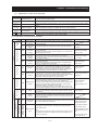
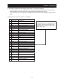
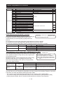
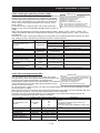
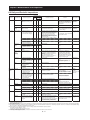
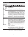
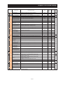
Safety Instructions
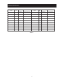
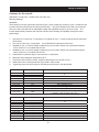
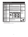
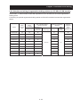
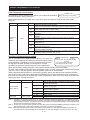
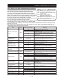
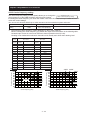
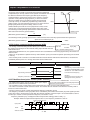
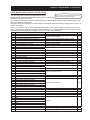
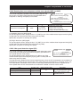
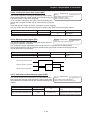
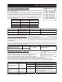
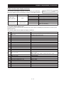
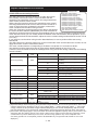
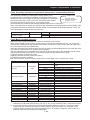
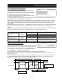
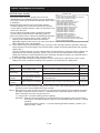
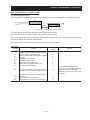
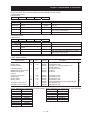
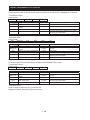
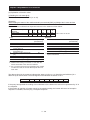
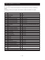
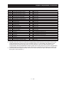
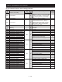
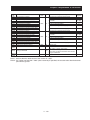
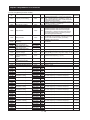
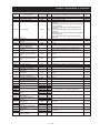
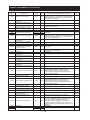
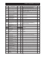
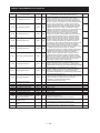
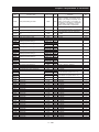
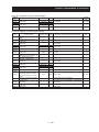
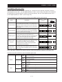
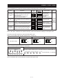
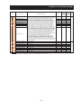
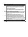
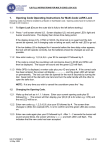
10. Distribution fuse/circuit breaker size marking is included in the manual to indicate that the unit
shall be connected with a Listed inverse time circuit breaker, rated 600 V with the current ratings as
shown in the table below:
Model No.
HF4312-5A5-N
Fuse Size (A)
Type
Rating
J
30 A
HF4312-5A5
HF4312-7A5
HF4312-011
HF4312-015
HF4312-022
HF4312-030
HF4312-037
HF4312-045
HF4312-055
Model No.
J
J
J
J
J
J
J
J
40 A
60 A
80 A
125 A
150 A
175 A
225 A
250 A
Fuse Size (A)
Type
Rating
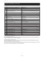
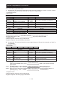
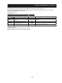
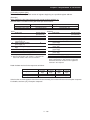
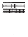
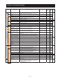
HF4314-5A5-N
J
15 A
HF4314-5A5
HF4314-7A5
HF4314-011
HF4314-015
HF4314-022
HF4314-030
HF4314-037
HF4314-045
HF4314-055
J
J
J
J
J
J
J
J
20 A
30 A
40 A
60 A
70 A
90 A
125 A
125 A
Circuit Breaker (A)
Type
Rating
-
-
Inverse time
30 A
Inverse time
Inverse time
Inverse time
Inverse time
Inverse time
Inverse time
Inverse time
Inverse time
40 A
60 A
80 A
125 A
150 A
175 A
225 A
250 A
Circuit Breaker (A)
Type
Rating
Inverse time
15 A
Inverse time
Inverse time
Inverse time
Inverse time
Inverse time
Inverse time
Inverse time
Inverse time
20 A
30 A
40 A
60 A
70 A
90 A
125 A
125 A
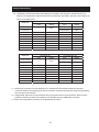
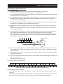
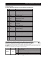
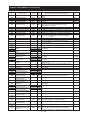
11. “Field wiring connection must be made by a UL Listed and CSA Certified closed-loop terminal
connector sized for the wire gauge involved. Connector must be fixed using the crimp tool specified by
the connector manufacturer.”
12. “Integral solid state short circuit protection does not provide branch circuit protection. Branch circuit
protection must be provided in accordance with the NEC and any additional local codes.”
13. “Motor over temperature protection is not provided by the drive.”
viii
' ../
44 00
4/4
444 4/4
44@ 12 4/4
4@ ) 4/@
4> ?+
3 0 4/@
' $
@4 @/4
@440
@/@
@4@- @/;
@@ @/<
@@4$
+
@/8
@@@
@/44
@@>
@/@4
@@;
@/@@
@@<5
-
1
<<-
@@-
2 @/@>
' >4 %
>/4
>@ :
$
%.%
1%5/;92 >/>
>@4 >/>
>@@"
-
>/;
>> :
$
-$ >/49
' !(0 1
;4 ;/4
;44 %)
19942 ;/4
;4@ %
199@2 ;/4
;4> 199>2 ;/4
;4; 0
10320.-
199;9G49G<2 ;/4
;4< 199<2 ;/@
;48 19982 ;/@
;4G 5
)
199G9A82 ;/@
;4A /)
99A0944:99;:@9;2 ;/>
;4F $
)
199F09>>09>;2 ;/>
;449 $
)
194909>8
09>A2 ;/>
;444 $
)
194@2 ;/>
;44@ %
194>2 ;/>
;44> 0
194;2 ;/>
+
;44; "
194<9GA9GF2 ;/;
;44< "
# 19482 ;/;
;448 "
/
194G2 ;/;
;44G :-
194A2 ;/;
;44A 194FFA2 ;/;
;44F H/-
19@@2 ;/<
;4@9 0
1)
219@>2 ;/<
;4@4 0
1)
219@;2 ;/<
;4@@ #
9
@1)
2 ;/<
;4@> 0
;/<
;4@; 0
1
2 ;/<
;4@< "
1
2 ;/<
;4@8 $"
19A92 ;/<
;4@G $
4
819A49A@
9A82 ;/8
;4@A 0
19F92 ;/8
;4@F ."
149@2 ;/8
;4>9 .
149>9F92 ;/8
;4>4 ?
149;2 ;/8
;@ =
;/G
;@4 %)1=9949949@9"994
"99A2 ;/G
;@@ I-
1=99;2 ;/G
;@> 19><2 ;/G
;@; =)
19942 ;/A
;@< 199@"994
"99A"94F=99;2 ;/A
;@8 5
19F4=99>99>99G9AA2 ;/F
;@G 5$%0,?5?$-19AG2 ;/F
;@A ,
1=99@=99>99;09>4"994
"99A2 ;/49
;@F )199>9A49A@2 ;/44
;@49 +)199;2 ;/44
;@44 ?+
13==3=@2199<998"994
"99A2 ;/4@
;@4@ =)
14;4
4;>9949G82 ;/4>
;@4> =)
14;<9;8"994
"99A2 ;/4;
;@4; 5,)
+
1944
94<494
49<
444
44;2 ;/4;
;@4< ?+
13==3=@219482 ;/4<
;@48 3,=19;<9A@2 ;/4<
;@4G 3,=
19;;4994942 ;/48
;@4A $
)
19;49;@9;>:99>:99;2 ;/4A
;@4F ."-1.219<4
9<F"994
"99A2 ;/@9
;@@9 =)198498@2 ;/@;
;@@4 )
198>
98A2 ;/@<
;@@@ )198F9G99FG2 ;/@<
;@@> 0.
199499<9G4
9G899;"994
"99A"9@4
"9@< "9;;2 ;/@8
;@@; $
/
,
1.@21=99@=99>9F@
9F8 "994
"99A2 ;/>9
;@@< ,
19FG9FA4>44>@2 ;/>4
;@@8 ?/
19A<9A82 ;/>@
;@@G 1994
99<99G99A "9@4
"9@82 ;/>>
;@@A 0
19982 ;/>8
;@@F ?
194@94>94<948"9@4
"9@8"9842 ;/>G
+
;@>9 5
,
19@4
9@8"994
"99A"9@4
"9@8 "9;9"9;4"4442 ;/;9
;@>4 %19@G2 ;/;4
;@>@ %
14>9
4>@2 ;/;@
;@>> 5)19A@2 ;/;>
;@>; 19>89A@2 ;/;>
;@>< ") ;/;;
;@>8 )
;/;<
;@>G .-1.$2
19F99F<9F82 ;/;8
;@>A "
/
19F@2 ;/;8
;@>F 1"994
"99A2 ;/;G
;@;9 ,1 %, "2
1"944
"94A"94F2 ;/;A
;@;4 1.=H
.=::5=4
5=G2194F9@9
9>< "994
"99A2 ;/;A
;@;@
1%!2
19>A9>F"994
"99A2 ;/<9
;@;> ,"
1.".2 ;/<4
;@;; 5
-15=$2
19>4"994
"99A2 ;/<@
;@;< =
/
1%0?2
199499@ "994
"99A2 ;/<@
;@;8 =
/
1=/$2
199499@"994
"99A2 ;/<@
;@;G =/
152
19AA9>>99G9@A
9>9"994
"99A2 ;/<>
;@;A "
1"52
199>99G"994
"99A2 ;/<;
;@;F 15$2
199>99G"49@"49>"994
"99A2 ;/<<
;@<9 #
1#502
1"994
"99A2 ;/<G
;@<4 1#0. 21"494"994
"99A2 ;/<G
;@<@ ?+1?52
1"994
"99A2 ;/<A
;@<> >/
15$5$0=,21"994
"99A2 ;/<A
;@<; "
1"5219;;"994
"99A:99<:9<9
:9<@ :9G9
:9G@2 ;/<F
;@<< 0,0
100219;;"994
"99A:99<:9<9
:9<@ :9G9
:9G@2 ;/<F
;@<8 1:.21"994
"99A2 ;/89
;@<G 10" $0""2 ;/89
;@<A 1"9@4
"9@82 ;/84
;@<F ,1 %, "2
1"9>4
"9>82 ;/8@
;@89 1.321"9@4
"9@<2 ;/8>
;@84 =)1#0=4#0=@#0=>#0=;#0=<21"9@4
"9@<"9;@ "9;>"9;<"9;82 ;/8>
;@8@ /
1 $% $2 19>;"9@4
"9@894894G2 ;/8<
;@8> 9:'
15219;;"9@4
"9@<"98>2 ;/8<
;@8; %/
)1%$219;;"9@4
"9@<"9<<
"9<A2 ;/88
;@8< 1"9
">21"9@4
"9@<"98@2 ;/88
;@88 H
1H%!4
H%!821"9@4
"9@8 "4;@
"4<F2 ;/8G
;@8G "
1"21"9@4
"9@82 ;/8A
;@8A "
1 .21"9@4
"9@8"9GG2 ;/8A
;@8F "
/
1=21"9@4
"9@89F@
9@@2 ;/8F
;@G9 5
1=21"9@4
"9@82 ;/8F
;@G4 :-
1%:=21"9@4
"9@8"98;2 ;/8F
;@G@ H
/
1H%"21"9@4
"9@8"9>A"9>F2 ;/G9
;@G> 1.21"9@4
"9@82 ;/G9
;@G; =
1=21"9@4
"9@82 ;/G4
+
;@G< 121"9@4
"9@82 ;/G4
;@G8 (
121"9@4
"9@82 ;/G4
;@GG 1"3""3@2
1
&[email protected] ;/G@
;@GA %,
1"4>9
"4;42 ;/G>
;@GF ;/G>
;@A9 ?+
1$:219FA9FF"9A<2 ;/G>
;@A4 =1"9@G9A42 ;/G;
;@A@ 31"9@A"9@F"498"49A
"4492 ;/G<
;@A> '
19A;9A<2 ;/G8
;@A; =
19>G#994
#94@2 ;/GG
;@A< /
1
/
219>A2 ;/GF
;@A8 /19>F#994
#94@2 ;/A9
;@AG 5'
1:9982 ;/A9
;@AA 5
10994099@2 ;/A9
;@AF %,
19;;9A<9@49@@2 ;/A4
;@F9 -
14@9
4@G"994
"99A"9@4"9@<2 ;/A@
;@F4 .
1
219<9
9<;2 ;/A;
;@F@ %
/
1:994
:99;:9>9
:9>;99>9<49A@2 ;/A8
;@F> %
/
;/AA
;@F; 5
1
2
109@<9FA2 ;/AF
;@F< ;/AF
;@F8 5
19949;;=9949;9
9;;:99@
:99< :9@9
:9@;:9<9
:9<@2 ;/F4
;@FG 5
9:'
19949;;=9949;9
9;; :99@
:99<:9@9
:9@;:9<9
:9<@:989:9842 ;/F@
;@FA $
)
19;;"9@G
"9@F:99>:99;2 ;/F>
;@FF =
1=%"219;;"994
"99A2 ;/F>
;@499$
)
19;;9;9
9;;"994
"99A"9@4
"9@<2 ;/F;
;@494
19;;9;82 ;/F<
;@49@$
)H.
19;;9;9
9;<2 ;/F8
;@49>:/
)/
19;;=9949;9
9;;:99@
:99< :9@9
:9@;:9<9
:9<@2 ;/F8
;> =
0!=-%
"
;/FA
;>4 =
)0!=-%
" ;/FA
;>@ "
;/FA
;>> 0!
;/FF
;>; $
)
;/499
;>< $
)
;/499
;>8 0
;/494
;>G ?
15
2 ;/49>
;>A ;/49<
;>F 0
;/49<
;>49 5
;/49<
;>44 :
;/498
;>4@ ;/49A
;>4> %
;/49F
;>4; 1"04
"0>2 ;/449
;>4< 5,
150.2 ;/449
+
;>48
/
1%!%H2 ;/444
;>4G =
,
1=%$%$2 ;/44@
;>4A 0
;/44@
;>4F $
;/44@
;>@9 5
/
;/44>
;>@4 0) ;/44;
;; "
=
;/44<
;;4 "
5"
;/44A
;;@ "
/$#
;/4>4
' &($
<4 ?
"
$
</4
<44 ?
</4
<4@ %
</<
<4> $
</F
<@ "
</49
' 2"
$
84
8@
8>
8;
8<
88
8G
8A
0
8/4
844 .
8/4
84@ " 8/4
84> 0
8/4
.0
8/@
!
$ 8/>
3
$ 8/>
"-"
" 8/;
."/"
H" 8/<
%
H 8/<
,%3
"0
8/8
' 3 G4
G@
5
G/4
?+
G/;
' 4,5
A4
A@
A>
A;
0
.5 A/4
A/4
=
A/@
?+=
A/>
+
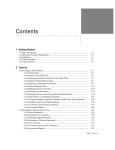
Contents
Appendix
Appendix ··················································································································· A - 1
Index
Index ····················································································································· Index - 1
Warranty
xiv
' ../
'' $*'
' '$ $
$'
%
44 00
4/4
4@ ) 4/@
4> ?+
3 0 4/@
' ../
'6'$6$
' $
-
142 "-
1
2
1@2 "-
-
1>2 "-
5
=4/4H
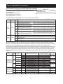
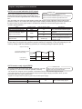
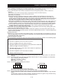
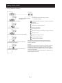
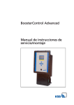
㼁㻺㻵㼀㻌㻺㼛㻚㻌㻦㻌㻴㻲㻠㻟㻝㻠㻙㻡㻭㻡 㻛㻌㻹㼛㼐㼑㼘㻌㻺㼛㻚㻌㻦㻌㻴㻲㻠㻟㻜㻠㻙㻡㻭㻡
㼂 㻝㻼㼔
㻭
㻵㼚㼜㼡㼠㻌㻛㻌㻱㼚㼠㼞㼑㼑㻌㻦㻌㻡㻜㻴㼦㻘㻢㻜㻴㼦
㻝㻟㻌㻭
㻡㻜㻴㼦㻘㻢㻜㻴㼦 㻟㻤㻜㻙㻠㻤㻜㼂 㻟㻼㼔
%
㻝㻞㻌㻭
㻻㼡㼠㼜㼡㼠㻌㻛㻿㼛㼞㼠㼑㻌㻦㻌㻜㻚㻝㻙㻠㻜㻜㻴㼦 㻟㻤㻜㻙㻠㻤㻜㼂 㻟㻼㼔
㻹㻲㻳㻌㻺㼛㻚
㻹㻭㻿㻿㻌㻦
5
㻌㻌㻌㻌㻌㻌㻌㻌㻌㻌㻌㻌㻌㻌㻌㻌㻌㻌㻌㻌㻌㻌㻌㻌㻌㻌㻌㻌㻌㻌㻌㻌㻌㻌㻌㻌㻌㻌㻌㻌㻌㻌㻌㻌㻌㻌㻌㻌㻌㻌㻌㻌㻌㻌㻌㻌㻌㻹㼍㼐㼑㻌㻵㼚㻌㻶㼍㼜㼍㼚
=4/@"
%
)'%
+
$
5
:=/;>9 Ș 5
-
4/4
' ../
"'$
7
=
)
)
&
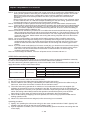
142 1@2 51=! 2
1>2 .
1;2 "
)
/ H
/ "
)
(08/
$%6
$
+
1
:=;>4/94<:=;>4/9@@2
=
0%?
H
.
5
$
-
5
?+
=
-
=
0
4
0
@
"
-
?+
-
4/@
' $
'' $*'/
'
.
$'/
%
$
%
/' 0% /
@4 @/4
@@ @/<
' $
㸟 / /%
-
/ .
%
-
/ %
-
(
/ 0
1
2
%
-
/ %
-
(
/ %
-
(
/ .
%
-
(
/ /
+
+
+
%
-
/ $
).
(
.
@/4
' $
6
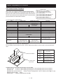
142 $
$
.
-
.
.
1@2 5
$1
4<9E"2
12
-
H
-
1-
2
I
142
449
@49
<
<
+."
-
@@
4<
<<-
1@2
1>2 1/49E"
C<9E"2
<
/
-
%
1
2
1;2 :
1@9B
F9B:2
(
"
+
1<2 (
=
@/@
' $
182 1G2 -
/
0
3
3
12
1#2
0
1A2 '
-
-
'
-
)
$
-
$
1-2
$
+
1F2 +
1-2
<<
G<
44
4<
@@
H
G9B
12
@;@
>4@
;><
<G<
A@9
4499
4>;<
48@<
4FG<
H
499B
12
>@<
;@<
899
A99
44<9
4<<9
4F99
@>99
@A99
?
1B2
F;;
F;8
F;A
F;F
F<9
F<9
F<4
F<4
F<4
@/>
>9
>G
;<
<<
' $
9:
142 =
@@-
%-(
5
1@2 =
>9-
<<-
42 =
"
-
-
@2 =
&.
@/;
' $
㸟 / %
-
-
/ "
-
)%
-
-
/ -
%
-
-
/ 0
%
-
-
(
/ .
%
㸟 / -
"
%
-
(
/ .
/
%
-
/ .
"
1#32%
-
(
/ .
."1040 2%
-
/ "
/--
%
-
/ #
/--
12%
-
/ .
/ $
) %
-
/ 54
%
-
-(
/ 5
/
$
%
-
-(
@/<
' $
%
$%
$0 %
$/'
>/
@993&@99
@;93C49B/4<B
1<9,89:'D<B2
;993&>A9
;A93C49B/4<B
1<9,89:'D<B2
-
<4
15@/@92
0
.(
1-2
5
6
7
5
7
U
W
0%?
H
:'
3 -
B
#
0!
4
=#
@
5$
3
1
3&6
%&
)%
)$
)5
=
:
35
'&9
3
-
1
2
1
@@-
/
.$2
$
1&
2
;
')/
1A
2
')0
1<2
83)
567
)54
20
.
10
2
$
63
%&
7+
61
9
53
9
493."14@2
95)
61
/49
C493."14@2
95)
;
@914@2
,5)
&20
1
2
9
4931492
1
2
)&
55
=)
<99
@999
,0
9
3
5$%0
?5?$
#
8
56
=
NȐ
NȐ
'&9
%
4
Ȑ
$09
%
@
(*
;
@91492
$0,
$/.
1
@993
2
$/"
1
;993
2
15@/442
@/8
' $
142 ?+
5
5$
1H4H@H>2
#3
1$4$@$>2
040
1C4C2
00
1C02
0 1C/2
?1!2
$
.
"
"
"
>/
."
?+-
-
(
040
1."H2
"
+-
1$0
@@-
2
"
-1.#2
"
/.
1
@993
2
/"
1
;993
2
1@2 ?+
5
0
"%
=
"
%
.1
2
0
=)
C3
$
1
2
=)
3=
=)
1
2
3=@
+
)
1
2
=
=)
12
3
1
2
12
=
.
1
2
0@;
"
1
2
=
5$
?5
%!
5
#$
.=
.=H
.
$
)
13=3=@=2
132.
$493."
3=3=@=
19
493."2)
493
+)
$
+)
493
*94;*
19
D493."2
)
3=
=
)
13=@2
1;
@9."2)
@9
+)
$=
#$
#$
$
*9
493."
*
$
)
)1
2
H.)
-
$
*;
@9."
*
$
)
)12
H.)
-
$
*9
493."
10
2*
$
)
)
12
H.
)
-
)
=
*
)**
*
9,493."
<9B
$@;3."
$
10@;2
1$:2
1=2-
.
?
&@9
&49-
&
/9>
C4@3."
&49-
& 9
r4@3."
&49-
+
&@;
+
&@
&
@<9
+
&4@
+)&>8
-:'
+
&499
6"
=
$
=
7
3
0"5&4A3."
5
8F
0"5&;G-
5$
+
&
0"5&@G
5$%! 3."
+
=
1>2*?
*1
@/A2
H
@G3."
&
<8
@/G
' $
%
5
5
5
0"5
#0=
.3
4
@
>
%
.1
2
"
=
="
=
=
$
.
$
-
(
10"52
-
0@;0"5
-
("
1
2
0"5
-
$
+
(
0"5
+
5
<4
#0=
>
*"98@*
#0=
4
#0=
@+
12$
%
-
?
3
%
&;3
+
&@G3."
$
+
1
2 6#0=7
6>7
&<9
5
;>
1+
2
"
=/="&@<93"@
12
9@
1
2
=/="&@<93"4
12
9@
0
%==
0
% 0
% 1
2
"9>894
"9>899
1
2
1.2
4993"49
1
1
1
<3."499
19
19
19
1
1
1
?
1
19
1
1
19
1
5
$:
"
+
-
$"
6
7
?+
&499
&>-
$
(
9
FFFF
9
A3."
67
."A3
49-Ȑ
$:
$
4-Ȑ
"
1>2 ?+
$1542
1
2
=
@/F
@/A
' $
*'%
1
2
/ $
1
2
"0#
&$
$
%
-(
/ 5$%!
+
?
+
$65$7
&
$1 %2
15$2
$
1?>G2
$6%!7
&
$1 "2
1?2
$
"0#
$-
1?>G2
&
%!
1?>G2
-
15$2
%15$2
65$7
1?>G21$
?>G
2
/ $
54
% 1
54
%==
2
&
54-
5
54
65$76%!7
5
54
54%==
?
1
2
54% ?
1<2
54% 1
%==
2
?
1>21<2
65$7
6%!7
$65$7
6"9947
,1 %, "2
6"9447142
$6%!7
6"99>7
,1 %, "2
6"94>71421@2
51;2
51;2
51;2
51;2
=
=
=
=
4A15$2
991 %2
981%!2
991 %2
65$76%!7
*4A
15$2*1>2
=+
1
2
4A15$2
51;2
5
54
% 4A15$2
=+
1
2
991 %2
51;2
5
54
% 991 %2
=+
1
2
8;1?2
51;2
1 2
=+
1
2
941 "2
51;2
5
54
% 941 "2
4 *4A15$2*
*,1 %, "2*
*991 %2*
@ *"99>**8;1?2**"94>**941 "2*
> *4A15$2*
65$76%!7
54
% *
1
2*54
% ?54)
%==
/
?+&54
% *4A15$2*
?51
*"99@*2*"99@*
*
1
2*
*4A15$2*
5$1*"994*2
?54)
%==6?57
*"99@*65$7
*"994**
1
2**4A15$2*
; =
*8;1?2*
%!
$
54
% < 54
% 65$76%!7
/
@/F
' $
554
㹍㹌
51
&%==2
2))
21
& 1%5/;42
&
:=/;>9
54% :=/;>9
54%==
:=/;>9
:=/;>9
6/?%"%0%7
$
65$76%!7
+
65$76%!7
54
% -
/
/
&554@
5
.
*% *
0
%==
1
&% 2
%
554@
5
% H
@/49
' $
'%
142 "
/
/
49
/
-
0 '
-
6"
7 <</G<-1
+2
15$040 #302
5
+
+
%
-
42 15$2
/"
/--
12
15$2
/#/--
/)
-
)
/
$
/.
12
1
2
$
+
1=
2
/$
/
/
/
5
.
/.
5
&
$&$
5&$
/
$
-(
142*
*
/"
&
/
>B
/
49<99I3
/
?+&$
/
/.
>
%
@2 1#32
/#-
?
)
)
/.
/
@/44
' $
/
/
+@91
;993
2
5
.
/
/$"
44
$
"
>2 ."
10402
/ #
."
1."H2
004
(
."H
/ $."H<
(
."H
(
."H
;2 ?+-
1002-
10 2
/ @@-
/-1.$2
-
+-
00
.
+-
5
-1.$2
/ >9-
/-1.$2
-
)
-
+-
"
0 -
0 / $
-<
/ .
+-
-
<2 1?1!2 2
/ -
/ ??
@993
/.
1
/
499
2
;993
/"
1
/
49
2
/ #
--
/ /
@/4@
!
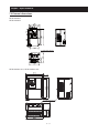
' $
1@2 H
$
-
$
:=;>4@/<</ 4
4
:=;>4;/<</ ?1!2 ?1!2
04
0
0
1C42
1C2
1/2
44&;
!
&;
%&;
$040
'
' 5,#$ %.
';% %%
6
$6
6
,?"
7㻌
$
?"
㻌
1842
.12
18@2
1H42
5
1H@2
$
1H>2
#
1$42
3
1$@2
1$>2
0-
$
-
0
5
1842
5
5
18@2
1842
18@2
??"
5
.12
.?"
.12
5
1
2
@/4>
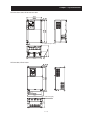
' $
$
4 4
"
0
:=;>4@/<<
:=;>4@/G<
1H42
5
1H@2
$
1H>2
04
1C42
0
1C2
1/2
#
1$42
3
1$@2
1$>2
:=;>4;/<<
:=;>4;/G<
040
?1!2
44&;
?1!2
!
&<
'
' 5,#
$
%.';% %%
6
$6
!
(1
2
,
?"
%&<
6
,?"
:=;>4@/944
:=;>4;/944
44&;
!
&<
%&8
??"
.?" 1
2
4 4
"
0
:=;>4@/94<
1H42
5
1H@2
$
1H>2
04
1C42
0
1C2
1/2
#
1$42
3
1$@2
:=;>4;/94<
1$>2
:=;>4;/9@@
44&;
040
?1!2
!
(1
2
,
?"
!
&8
?1!2
%&8
'
' 5,#
$
%.';% %%
6
$6
6
,?"
7
:=;>4@/9@@
44&;
!
&8
??"
%&A
.?"
1
2
@/4;
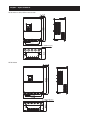
' $
$
4 4
"
:=;>4@/9>9
?1!2
5
$
04
0
1H42 1H@2 1H>2 1C42 1C2
1/2
44&;
?1!2
#
3
1$42 1$@2 1$>2
!
&8
%&A
040
!
(1
2
,
?"
:=;>4;/9>9
'
' 5,#
$
%.';% %%
6
$6
44&;
6
,?"
7
!
&8
%&8
:=;>4@/9>G
:=;>4;/9>G
44&;
!
&A
??"
.?"
1
2
4 4
FKDUJHOXPS
1H42
5
1H@2
$
1H>2
04
1C42
0
1C2
?1!2
$040
%&A
1/2
#
1$42
3
1$@2
1$>2
!
(1
2
,
?"
?1!2
?1!2
'
'5,#
$
%.';% %%
6
$6
:=;>4@/9;<
:=;>4;/9;<
:=;>4;/9<<
6
,?"
7
44&;
!
&A
%&A
??"
.?"
1
2
@/4<
' $
$
1H42
5
1H@2
$
1H>2
04
1C42
0
1C2
$040
?1!2
(*
4 4
1/2
#
1$42
3
1$@2
1$>2
?1!2
!
(1
2
,
?"
'
'5,#
$
%.';% %%
6
$6
:=;>4@/9<<
6
,?"
7
44&;
!
&A
%&49
??"
.?"
1
2
@/48
' $
&H-
?"
12
$
-
?"
1H-
)
2
-
$+
-
+)1
2
$G<-
?"$
?"">
㻌
@993
1
&@993"<9:'2
<<-㹼
44-
4<-㹼>G- ;<-㹼<<-
;993
1
&;993"<9:'2
9G<-㹼
<<-㹼
4<-㹼>G- ;<-㹼<<-
>G-
44-
";A
"@>
"@>
"<
"F<
"<8
"<8
?" "94
"94
"94
"9@
"9@
"9@
"9@
?"
@/4G
' $
1>2 )
51;2*
*
0
$
499
>99
512
<9
499
1
2
4& $)
5
>/;/
)/
@& 5-
1#-
2
>& #/--1?H2
;& #
1:32
+
G<E"
<& +@9-
8& #9G<@
G& $
)
H
$+
)
-
A& 5/--1?H2
.
/?H
/?H/
F& "3
->9,-
49&3
-
$
3?H
+499"3
U
W
1
/
2
3
1"
2
."
35
-
-
(*
1
/
2 "
=
H"
.
#
>B
<99I3
$
$
"
12
$
#
1
2
#
#
#
-
)
)
"
)
#
1$
2
#
/
"
"
"
149
2
$
@/4A
' $
1;2 &=
"?#H
?"
#H"#H5
$
)
;993
@993
?+
!
-
!
/
5'
1@2
" $
1$& )1 /2
1-2
0 5$#3 1@2
0
004 2
1@2
:=;>4@/<</ @91>92
<<
<<
<<
<<
< <</<
:=;>4@/<<
@;1;92
G<
:=;>4@/G<
A
A
A
<
A/< @;1;92
44
:=;>4@/944
4;
4;
4;
8
4;/8 ;91;;2
4<
:=;>4@/94<
@@
@@
@@
8
@@/8
;<1;F2
@@
:=;>4@/9@@
>A
>9
>A
A
>A/A
A41AA2
>9
:=;>4@/9>9
891@@@2
>9
̿
A
89/A
A41AA2
>G
:=;>4@/9>G 4991>A@2
>A
̿
A2
499/A A41@92
;<
:=;>4@/9;< 4991>A@2
>A
̿
A2
499/A A41@92
<<
:=;>4@/9<< 4<9189@2
89
̿
49 4<9/49 4F81@@2
:=;>4;/<</ @91>92
<<
><42
><42
><42
<
></<
:=;>4;/<<
@;1;92
G<
:=;>4;/G<
><
><
><
<
></< @;1;92
44
:=;>4;/944
<<
<<
<<
8 <</8 ;91;;2
4<
:=;>4;/94<
A
A
A
8
A/8
;<1;F2
@@
:=;>4;/9@@
4;
4;
4;
8
4;/8
;<1;F2
>9
:=;>4;/9>9
@@
@@
̿
8
@@/8
;<1;F2
>G
:=;>4;/9>G
>A
@@
̿
A2
>A/A
A41@92
;<
:=;>4;/9;<
>A
@@
̿
A2
>A/A
A41@92
<<
:=;>4;/9<<
89
>9
̿
A2 89/A A41@92
"-
/--1?H2
?
=<9 3<9<9
=499
=499
=499
=@@<
=@@<
=;99
=;99
=;99
349989
3499G<
3499499
3@@<4<9
3@@<@99
3;99@<9
3;99>99
3;99><9
=>9 3>9>9
=>9
=<9
=499
=499
=@@<
=@@<
=@@<
=@@<
3>9>9
3<9<9
349989
3499499
3@@<4@<
3@@<4<9
3@@<4G<
3@@<@99
=<9 3<9;9
=<9
=499
=499
=@@<
=@@<
=@@<
=@@<
=;99
5"/4 1J2
3<9<9
5"/@ 1J2
349989 5"/@5 1J2
3499G< 5"/> 1J2
3@@<4@< 5"/< 1J2
3@@<4<9 5"/G 18 2
3@@<4G< 5"/A 1G 2
3@@<@@< 5"/49 1A 2
3;99@<9 5"/44 149 2
=>9 3>9@9
=>9
=<9
=<9
=499
=499
=499
=@@<
=@@<
1
2
=(?
5"/</41J2
3>9>9
5"/</41J2
3<9;9
5"/4 1J2
3<9<9
5"/@ 1J2
349989 5"/@5 1J2
3499499 5"/> 1J2
3499499 5"/; 1J2
3@@<4@< 5"/< 1J2
3@@<4<9 5"/G 18 2
&"
:31+&G<E"2
42:=;>9;/<<:=;>4;/<<
:=;>4;/<</ @@
@㸧0
1
#H2
0
-
@/4F
' $
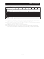
1<2 "
$
44
44
1"
2
0
/
ձ @993
&
ղ <4
@99
@;931C49B/4<B2
1<9,89:'D<B21@A@
>>F3."2
ճ "
;993
&
>A9
;A931C49B/4<B2
1<9,89:'D<B21<>G
8GA3."2
-
<4
1442
15$2&
@
/ #-4@< 441'&;2
/ "
>
1$
)&4@ +
)&4; 2
/ 1
442
1
5$2
-
/
/ ."
1442*99*
*,1 %, "2*
1
"9>4
"9>82
16#0=7
6>72
1="==2*94**,
1 %, "2*
."
@/@9
' $
'
142 42 $"%"
,%
.
.
+1"-+
2
@2 #/1
&9G<@2
1$
)&9G +
)&9A 2
>2 $
@9
+@9
;2 5
1
2
)
%
<2 $
1$:2"
5
1
2
$
@9
5)
$: = " #$
0"5 " .=H.= 5
$
82 1
2
1
2
G2 /
A2 .
C3"%
0@;
"
%
1@2 H
C3
3=@ 3 =
"% 3=
=
$:
=
0@; 0"5
"
"
.=H
#$
%!
.= 5
5$
?5
>
@
4
%
#0=
.3
="
=
=
$'&>1$
)&9G +
)&9A 2
1>2 5
/ =
-
$
(
0@;
0"5
-
0"5"(
@/@4
' $
1;2 "
+
1
(
-2
0@;
5
0"5
"
5-
0@;
5
0"5
."@;3
=
=
"%
"%
%
%
."@;3
"%
0@;
5
"
0@;
"%
."@;3
0"5
."@;3
"
."@;3
0"5
"
=
=
5
."@;3
5
%
%
1<2"
#0=
%
"%
%
5
5-
."@;3
.3
"%
#0=
.3
."@;3
!
'$ /
)
1%5/;9%5/;@
%5/;>2
/ ))
5
.
"5/414/2
"5/>1>/2
&
:#$0<0";0//&5)
1:"H2
/ $
>
>
@/@@
' $
&
$/
.*:
)
&&::%$+
$:=/;>9 Ș <<
@@-
-
"
-
00
)
1-2
149B?.2
)1B2
1Ȑ2
)1㸣2
1Ȑ2
.
1㸣2
1Ȑ2
:=;>4@/<</ :=;>4@/<<
<<
@9
@9
48
<9
:=;>4@/G<
G<
@9
@9
49
<9
:=;>4@/944
44
49
4><
49
<9
:=;>4@/94<
4<
49
49
G<
><
:=;>4@/9@@
@@
49
88
<
499
><
49
:=;>4;/<</ :=;>4@/<<
<<
@9
A>
G9
@99
:=;>4;/G<
G<
@9
>8
><
4<9
:=;>4;/944
44
49
<;
><
4<9
:=;>4;/94<
4<
49
;9
@;
499
:=;>4;/9@@
@@
49
@G
@9
499
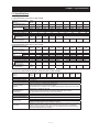
@/@>
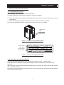
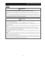
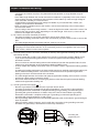
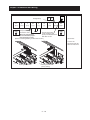
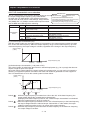
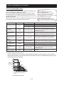
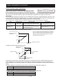
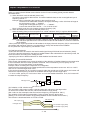
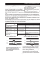
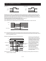
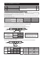
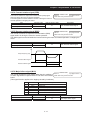
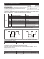
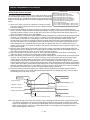
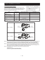
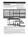
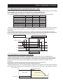
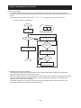
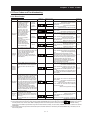
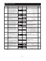
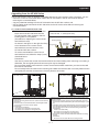
Chapter 3 Operation
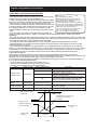
This chapter describes typical methods of operating the inverter, how to operate
the digital operator, and how to make a test run of the inverter.
3.1
Operating Methods ····································3 - 1
3.2
How To Operate the Digital Operator (OS-40) ··3 - 3
3.3
How To Make a Test Run ····························3 - 10
Chapter 3 Operation
3.1 Operating Methods
㸟 WARNING
- While power is supplied to the inverter, do not touch any terminal or internal part of the inverter, check
signals, or connect or disconnect any wire or connector. Otherwise, you run the risk of electric shock
or fire.
- Be sure to close the terminal block cover before turning on the inverter power. Do not open the
terminal block cover while power is being supplied to the inverter or voltage remains inside. Otherwise,
you run the risk of electric shock.
- Do not operate switches with wet hands. Otherwise, you run the risk of electric shock.
- While power is supplied to the inverter, do not touch the terminal of the inverter, even if it has stopped.
Otherwise, you run the risk of injury or fire.
- If the retry mode has been selected, the inverter will restart suddenly after a break in the tripping
status. Stay away from the machine controlled by the inverter when the inverter is under such
circumstances. (Design the machine so that human safety can be ensured, even when the inverter
restarts suddenly.) Otherwise, you run the risk of injury.
- Do not select the retry mode for controlling an elevating or traveling device because output
free-running status occurs in retry mode. Otherwise, you run the risk of injury or damage to the
machine controlled by the inverter.
- If an operation command has been input to the inverter before a short-term power failure, the inverter
may restart operation after the power recovery. If such a restart may put persons in danger, design a
control circuit that disables the inverter from restarting after power recovery. Otherwise, you run the
risk of injury.
- The [STOP] key is effective only when its function is enabled by setting. Prepare an emergency stop
switch separately. Otherwise, you run the risk of injury.
- If an operation command has been input to the inverter before the inverter enters alarm status, the
inverter will restart suddenly when the alarm status is reset. Before resetting the alarm status, make
sure that no operation command has been input.
- While power is supplied to the inverter, do not touch any internal part of the inverter or insert a bar in it.
Otherwise, you run the risk of electric shock or fire.
㸟 CAUTION
- Do not touch the heat sink, which heats up during the inverter operation. Otherwise, you run the risk of
burn injury.
- The inverter allows you to easily control the speed of motor or machine operations. Before operating
the inverter, confirm the capacity and ratings of the motor or machine controlled by the inverter.
Otherwise, you run the risk of injury and damage to machine.
- Install an external brake system if needed. Otherwise, you run the risk of injury.
- When using the inverter to operate a standard motor at a frequency of over 60 Hz, check the allowable
motor speeds with the manufacturers of the motor and the machine to be driven and obtain their
consent before starting inverter operation. Otherwise, you run the risk of damage to the motor and
machine and injury
- During inverter operation, check the motor for the direction of rotation, abnormal sound, and
vibrations. Otherwise, you run the risk of damage to the machine driven by the motor.
3-1
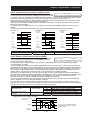
Chapter 3 Operation
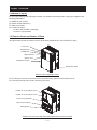
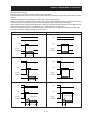
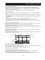
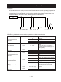
You can operate the inverter in different ways, depending on how to input the operation and
frequency-setting commands as described below.
This section describes the features of operating methods and the items required for operation.
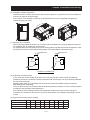
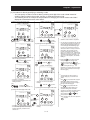
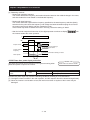
(1) Entering operation and frequency-setting commands from the digital operator
This operating method allows you to operate the inverter through key operations on the standard
digital operator mounted in the inverter or an optional digital operator.
When operating the inverter with a digital operator alone, you need not wire the control circuit
terminals.
(Items required for operation)
1) Optional digital operator (not required when you use the standard digital operator)
Digital operator
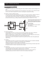
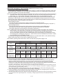
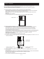
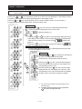
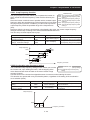
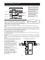
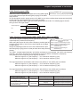
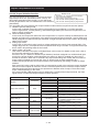
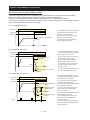
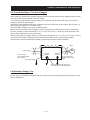
(2) Entering operation and frequency-setting commands via control circuit terminals
This operating method allows you to operate the inverter via the input of operation signals from
external devices (e.g., frequency-setting circuit and start switch) to control circuit terminals.
The inverter starts operation when the input power supply is turned on and then an operation
command signal (FR or RR) is turned on.
You can select the frequency-setting method (setting by voltage specification or current specification)
through the input to a control circuit terminal according to your system. For details, see Item (2),
"Explanation of control circuit terminals," in Section 2.2.1 (on pages 2-7 and 2-8).
(Items required for operation)
1) Operation command input device: External switch or relay
2) Frequency-setting command input device: External device to input signals (0 to 10 VDC, -10 to +10
VDC, or 4 to 20 mA)
Control circuit
terminal block
+V
Frequency-setting command
input device (control)
VRF
BC
COM
FR
Operation command input
device (switch)
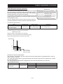
(3) Entering operation and frequency-setting commands; both from a digital operator and via control
circuit terminals
This operating method allows you to arbitrarily select the digital operator or control circuit terminals as
the means to input operation commands and frequency-setting commands.
(Items required for operation)
1) See the items required for the above two operating methods.
3-2
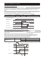
Chapter 3 Operation
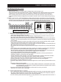
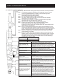
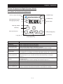
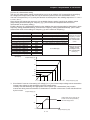
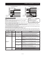
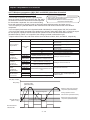
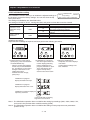
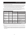
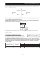
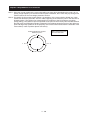
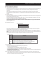
3.2 How To Operate the Digital Operator (OS-40)
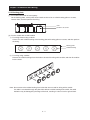
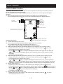
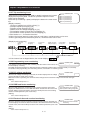
3.2.1 Names and functions of components
Monitor (4-digit LED display)
POWER lamp
POWER
ALARM
RUN (operation) lamp
RUN
PRG (program) lamp
ALARM lamp
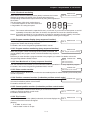
Hz
V
A
PRG
kW
Monitor lamps
%
RUN key enable
RUN key
STOP
RUN
FUNC (function) key
FUNC
RESET
1
2
STR
STR (storage) key
2 (down) key
1 (up) key
STOP/RESET key
Name
POWER lamp
Function
Lights when the control circuit power is on.
ALARM lamp
Lights to indicate that the inverter has tripped.
RUN (operation) lamp
Lights to indicate that the inverter is operating.
PRG (program) lamp
Lights when the monitor shows a value set for a function.
This lamp starts blinking to indicate a warning (when the set value is invalid).
Monitor
Displays a frequency, output current, or set value.
Monitor lamps
Indicates the type of value and units displayed on the monitor.
"Hz" (frequency), "V" (voltage), "A" (current), "kW" (electric power), and "%" (percentage)
RUN key enable LED
Lights up when the inverter is ready to respond to the RUN key.
(When this lamp is on, you can start the inverter with the RUN key on the digital
operator.)
RUN key
Starts the inverter to run the motor. This key is effective only when the operating device is
the digital operator.
(To use this key, confirm that the operating device indicator lamp is on.)
STOP/RESET key
Decelerates and stops the motor or resets the inverter from alarm status.
FUNC (function) key
Makes the inverter enter the monitor, function, or extended function mode.
STR (storage) key
Stores each set value. (Always press this key after changing a set value.)
1 (up) or 2 (down) key
Switches the inverter operation mode (among monitor, function, and extended function
modes) or increases or decreases the value set on the monitor for a function.
3-3
Chapter 3 Operation
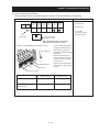
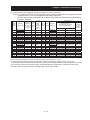
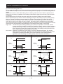
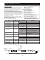
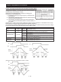
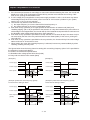
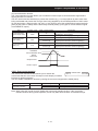
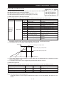
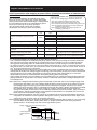
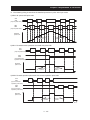
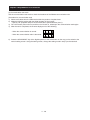
3.2.2 Code display system and key operations
This section describes typical examples of digital operator operation (in basic and full display modes) and
an example of special digital operator operation in extended function mode U.
The initial display on the monitor screen after power-on depends on the setting of function "b038". For
details, see Section 4.2.81, "Initial-screen selection," (on page 4-76).
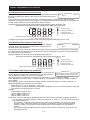
When the setting of function "b038" is "01" (factory setting), the monitor initially shows
the setting of function "d001" (output frequency monitoring). Pressing the
changes the display to
FUNC
as
key in this status
.
Note: The display contents on the monitor depend on the settings of functions "b037" (function code
display restriction), "b038" (initial-screen selection), and "b039" (automatic setting of user
parameters). For details, see Sections 4.2.80, "Function code display restriction," (on page 4-74),
4.2.81, "Initial-screen selection," (on page 4-76), and 4.2.82, "Automatic user-parameter setting," (on
page 4-77).
Item
Function code
Function code display
restriction
b037
Data
00
01
02
03
04
00
Initial-screen selection
(Initial display at
power-on)
b038
(*1)
Selection of automatic
user-parameter settings
b039
(*1)
01
02
03
04
05
00
01
Description
Full display
Function-specific display
User setting
Data comparison display
Basic display (factory setting)
Screen displayed when the [STR] key was pressed last
(same as the operation on the HF-430 series)
d001 (output frequency monitoring)
d002 (output current monitoring)
d003 (rotation direction monitoring)
d007 (Scaled output frequency monitoring)
F001 (output frequency setting)
Disable
Enable
*1 Not displayed with the factory setting
* The following procedure enables you to turn the monitor display back to
regardless of the current display mode:
- Hold down the FUNC key for 3 seconds or more. The monitor shows
alternately.
During this status, press the FUNC key. The monitor will show only
which is shown when the FUNC is pressed.
or
(*1)
and
(*1)
or
(*1),
*1 The monitor shows
only when the motor driven by the inverter is stopped. While the
motor is running, the monitor shows an output frequency.
3-4
Chapter 3 Operation
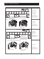
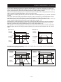
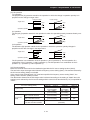
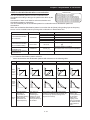
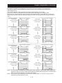
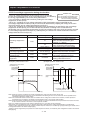
(1) Example of operation in basic display mode ("b037" = "04" [factory setting])
- Only basic parameters can be displayed in basic display mode. (All parameters in monitor mode,
four parameters in function mode, or 20 parameters in extended function mode)
- Other parameters are not displayed. To display all parameters, select the full display mode ("b037" =
"00").
<Displayable parameters and sequence of display>
No.
1
2
3
4
5
6
7
8
9
10
11
12
13
14
15
16
17
18
19
20
21
22
23
24
25
26
27
28
Display code
d001 to d104
F001
F002
F003
F004
A001
A002
A003
A004
A020
A021
A022
A023
A042
A044
A045
A085
b001
b002
b008
b011
b012
b013
b037
b083
b084
b090
b095
29
C021
28
C022
29
30
31
32
C036
H002
H003
H004
Item
Monitor display
Output frequency setting
Acceleration (1) time setting
Deceleration (1) time setting
Operation direction setting
Frequency source setting
Run command source setting
Base frequency setting
Maximum frequency setting
Multispeed frequency setting
Multispeed 1 setting
Multispeed 2 setting
Multispeed 3 setting
Manual torque boost
Control
V/F gain setting
Operation mode selection
Selection of restart mode
Allowable under-voltage power failure time
Retry-after-trip selection
Retry wait time after trip
Electronic thermal level
Electronic thermal characteristic selection
Function code display restriction
Carrier frequency setting
Initialization mode selection
DBTR usage ratio
DBTR selection
Setting of multifunctional output terminal
UPF
Setting of multifunctional output terminal
DRV
Alarm relay active state
Motor constant selection
Motor capacity selection
Motor pole selection
3-5
Note:
If a desired parameter is not displayed, check
the setting of function "b037" (function code
display restriction). To display all parameters,
specify "00" for "b037".
Chapter 3 Operation
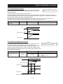
Key operation and transition of the
codes on display
Key operation and transition of the monitored data on display
Pressing the 1 or 2 key respectively scrolls up or down the code displayed in code display mode or
increases or decreases the numerical data displayed in data display mode.
Press the 1 or 2 key until the desired code or numerical data is shown. To scroll codes or
increase/decrease numerical data faster, press and hold the key.
Monitor mode
Pressing the FUNC key with a function code displayed shows the
FUNC
monitored data corresponding to the function code.
(Monitor display) (*1)
FUNC
or
STR
Pressing the FUNC or STR key with the monitored data displayed reverts
to the display of the function code corresponding to the monitored data.
* With the factory setting, the monitor shows
initially after
power-on.
Pressing the FUNC key in this status changes the display to
.
Function or extended function mode
Pressing the FUNC key with a function code displayed shows the data
corresponding to the function code.
(Data display) (*1)(*2)
Up to the
maximum limit
Data setting
Pressing the 1 or 2 key respectively increases or
decreases the displayed numerical data.
(Press the key until the desired data is shown.)
Pressing the STR key with numerical data displayed
stores the data and then returns to the display of the
corresponding function code.
Note that pressing the FUNC key with numerical data
displayed returns to the display of the function code
corresponding to the numerical data without updating
the data, even if it has been changed on display.
FUNC
FUNC
or
STR
Down to the
minimum limit
*1
*2
The content of the display varies depending on the
parameter type.
To update numerical data, be sure to press the
key after changing the data.
STR
3-6
Chapter 3 Operation
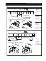
(2) Example of operation in full display mode ("b037" = "00")
All parameters can be displayed in full display mode. The display sequence of parameters matches
their sequence shown in Chapter 8, "List of Data Settings."
Key operation and
transition of codes on
display (in monitor or
function mode)
Key operation and
transition of monitored
data on display (in monitor
or function mode)
Key operation and
transition of codes on
display (in extended
function mode)
Key operation and
transition of monitored
data on display (in
extended function mode)
Pressing the 1 or 2 key respectively scrolls up or down the code displayed in code display mode or
increases or decreases the numerical data displayed in data display mode.
Press the 1 or 2 key until the desired code or numerical data is shown. To scroll codes or
increase/decrease numerical data fast, press and hold the key.
Monitor
mode
*1
FUNC
(Monitor
display)
*2
The content of the display varies depending on the
parameter type.
To update numerical data, be sure to press the
STR key after changing the data.
(*1)
FUNC
or
STR
Function
mode
FUNC
(*1) (*2)
(Data display)
(Data display)
(*1) (*2)
FUNC
or
Extended
function
mode A
STR
FUNC
FUNC
FUNC
or
STR
FUNC
FUNC
or
Extended
function
mode B
FUNC
or
STR
FUNC
Extended
function
mode C
FUNC
or
STR
FUNC
Extended
function
mode H
FUNC
or
STR
FUNC
Extended
function
mode P
FUNC
FUNC
FUNC
or
STR
or
STR
For the display and key
operation in extended
function mode U, see the
next page.
3-7
STR
Chapter 3 Operation
(3) Code/data display and key operation in extended function mode U
The extended function mode U differs in operation from other extended function modes because the
extended function mode U is used to register (or automatically record) other extended-function codes
as user-specified U parameters.
Key operation and
transition of codes on
display (in monitor or
function mode)
*1
*2
Key operation and transition
of codes on display (when
displaying extended-function
mode parameters from the
extended function mode U)
Key operation and
transition of codes on
display (in extended
function mode U)
The content of the display varies depending on the
parameter type.
To update numerical data, be sure to press the
STR key after changing the data.
Key operation and
transition of codes on
display (in monitor,
function, or extended
(*1) (*2)
(Data display)
Extended
function
mode A
FUNC
FUNC
or
STR
Extended
function
mode B
STR
Pressing the
key
reflects the value set here in
the corresponding parameter.
Note that the value is not
reflected in the corresponding
U parameter.
Extended
function
mode C
Extended
function
mode H
Extended
function
mode U
Extended
function
mode P
FUNC
FUNC
(Display with the
factory setting)
FUNC
FUNC
or
STR
Monitor
mode
You cannot restore the
display with the
STR
Pressing the STR key
stores the value set here
in the corresponding U
parameter.
key.
Function
mode
3-8
Chapter 3 Operation
(4) Procedure for directly specifying or selecting a code
- You can specify or select a code or data by entering each digit of the code or data instead of
scrolling codes or data in the monitor, function, or extended function mode.
- The following shows an example of the procedure for changing the monitor mode code "d001"
displayed to extended function code "A029":
1) Display the monitor mode code.
("d001" is displayed.)
("A029" is displayed.)
(*2)
Press the
key.
RUN
RUN
FUNC
STR
STOP/
RESET
RUN
STOP/
RESET
STOP/
RESET
FUNC
(*2)
(*3)
6) End the change of the extended function code.
FUNC
STR
STR
(Character "9"
is determined.)
FUNC
STR
- Character "9" in the first digit is blinking.
Press the 1 and
together.
2 keys
(*1)
Press the 1 key eight
times or the 2 key twice.
2) Change to the extended function mode.
5) Change the first digit of the code.
RUN
- Selection of code "A029" is completed.
* If a code that is not defined in the code list
or not intended for display is entered, the
leftmost digit (fourth digit) (character "A"
in this example) will start blinking again.
In such a case, confirm the code to be
entered and enter it correctly. For further
information, refer to Section 4.2.80. "
Function code display restriction," (on
page 4-74), Section 4.2.81, "Initial-screen
selection," (on page 4-76), Section 4.2.82,
"Automatic user-parameter setting," (on
page 4-77), and Chapter 8, "List of Data
Settings."
STOP/
RESET
RUN
FUNC
STR
FUNC
- Character "d" in the leftmost digit (fourth digit
from the right) starts blinking.
Press the
STOP/
RESET
STR
- Character "1" in the first digit is blinking.
2 key twice.
(*2)
("A001" is displayed.)
FUNC
Press the
STR
key.
("A021" is displayed.)
7) Press the FUNC key to display the data
corresponding to the function code,
change the data with the 1 and/or
2 key, and then press the STR key to
store the changed data. (*4)
Note that you can also use the procedure
(steps 1) to 6)) described here to change
the data. (*3)(*4)
(*3)
RUN
(*2)
STOP/
RESET
*1
RUN
STR
FUNC
STR
FUNC
- Character "A" is blinking.
- Pressing the [STR] key determines the
blinking character.
*2
- Character "2" in the second digit is
blinking.
(*2)
Press the
STR
FUNC
This procedure can also be used on
screens displaying a code other than
"d001".
STOP/
RESET
Press the
key
(to determine character "A").
1
key twice.
*3
If the FUNC key is pressed while the
leftmost (fourth) digit is blinking, the
characters having been entered to
change the code will be cancelled and the
display will revert to the original code
shown before the 1 and 2 keys
were pressed in step 1).
4) Change the second digit of the code.
3) Change the third digit of the code.
Press the
key.
STR
*4
RUN
RUN
FUNC
(Character "0" is
determined.)
STOP/
RESET
When changing data, be sure to press the
FUNC key first.
STOP/
RESET
FUNC
STR
STR
FUNC
- Character "0" in the third digit is blinking.
- Since the third digit need not be changed,
press the [STR] key to determine the
character "0".
If the FUNC key is pressed while a digit is
blinking, the display will revert to the
preceding status for entering the digit to
the right of the blinking digit.
(*2)
- Character "0" in the second digit is
blinking.
3-9
Chapter 3 Operation
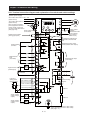
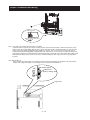
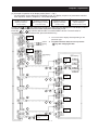
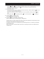
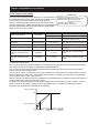
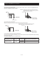
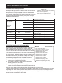
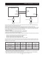
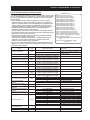
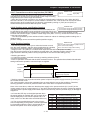
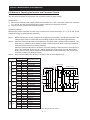
3.3 How To Make a Test Run
This section describes how to make a test run of the inverter that is wired and connected to external
devices in a general way as shown below.
For the detailed method of using the digital operator, see Section 3.2, "How To Operate the Digital
Operator."
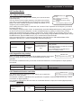
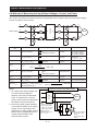
(1) When entering operation and frequency-setting commands from the digital operator:
(The operating procedure below is common to the standard and optional digital operators.)
ELB
3-phase
power supply
R
S
T
R
S
T
FR
RR
卒
卒
卒
RST
Default jumper position for sinking type inputs
(Alternatively, BC-PCS for sourcing type)
FRQ
TH
BC
PCS
P24
+V
VRF
IRF
VRF2
AMV
AMI
COM
U
V
W
Digital operator
P1
P
PR
N
FA
FB
FC
UPF
Motor
DC reactor
Braking unit
Alarm output contacts
卒
卒
卒
X3
OM
SP
SN
RP
SN
E(G)
Type-D grounding (200 V class model)
Type-C grounding (400 V class model)
(Operating procedure)
1) Confirm that all wirings are correct.
2) Turn on the earth-leakage breaker (ELB) to supply power to the inverter.
(The POWER lamp [red LED] of the digital operator goes on.)
* When using an inverter with the factory setting, proceed to step 5).
3) Select the digital operator as the operating device via the frequency source setting function.
- Display the function code "A001" on the monitor screen, and then press the FUNC key once.
(The monitor shows a 2-digit numeric value.)
- Use the 1 and/or 2 key to change the displayed numeric value to [02], and then press the
STR key once to specify the digital operator as the operating device to input frequency-setting
commands.
(The display reverts to [A001].)
4) Select the digital operator as the operating device by the run command source setting function.
- Display the function code "A002" on the monitor screen, and then press the FUNC key once.
(The monitor shows a 2-digit numeric value.)
- Use the 1 and/or 2 key to change the displayed numeric value to "02", and then press the
STR
key once to specify the digital operator as the operating device to input operation commands.
(The display reverts to [A002]. The operating device indicator lamp above the [RUN] key goes on.)
5) Set the output frequency.
FUNC
- Display the function code "F001" on the monitor screen, and then press the
key once.
(The monitor shows a preset output frequency. With the factory setting,
[0 Hz] is shown.)
- Use the 1 and/or 2 key to change the displayed numeric value to the desired output frequency,
and then press the STR key once to determine the frequency.
(The display reverts to [F001].)
6) Set the operation direction of the motor.
- Display the function code "F004" on the monitor screen, and then press the FUNC key once.
(The monitor shows "00" or "01".)
3 - 10
Chapter 3 Operation
- Use the 1 and/or 2 key to change the displayed value to "00" for forward operation or "01" for
reverse operation, and then press the STR key once to determine the operation direction.
(The display reverts to [F004].)
7) Set the monitor mode.
- To monitor the output frequency, display the function code "d001", and then press the FUNC key once.
(The monitor shows the output frequency.)
To monitor the operation direction, display the function code "d003", and then press the FUNC key
once.
(The monitor shows
for forward operation,
for reverse operation, or
for stopping.)
8) Press the RUN key to start the motor.
(The RUN lamp [green LED] goes on.)
STOP/
9) Press the RESET
key to decelerate or stop the motor.
(When the motor stops, the RUN lamp [green LED] goes off.)
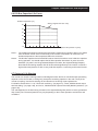
-
During the test run, confirm that the inverter does not trip while accelerating or decelerating the motor
and that the motor speed and frequencies are correct.
If a trip due to overcurrent or overvoltage has occurred during the test run, increase the acceleration
and deceleration time.
Make sure that there is enough margin to trip level by monitoring the output current (d002) and DC
voltage (d102).
3 - 11
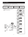
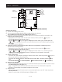
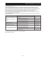
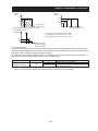
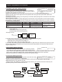
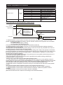
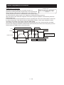
Chapter 3 Operation
ELB
3-phase
power supply
Operating box
R
S
T
FR
R
S
T
F
Digital operator
U
V
W
P1
P
PR
N
FA
FB
FC
DC reactor
Braking unit
㺃㺃㺃㺃
RR
RST
FRQ
TH
BC
PCS
UPF
Default: for sinking type
P24
+V
X3
OM
VRF
SP
IRF
SN
VRF2
AMV
RP
AMI
SN
COM
E(G)
Motor
Type-D grounding (200 V class model)
Type-C grounding (400 V class model)
(Operating procedure)
1) Confirm that all wirings are correct.
2) Turn on the earth-leakage breaker (ELB) to supply power to the inverter.
(The POWER lamp [red LED] of the digital operator goes on.)
3) Select the control circuit terminal block as the device to input frequency-setting commands by the
frequency source setting function.
- Display the function code "A001" on the monitor screen, and then press the FUNC key once.
(The monitor shows a 2-digit numeric value.)
- Use the 1 and/or 2 key to change the displayed numeric value to [01], and then press the
STR key once to specify the control circuit terminal block as the device to input frequency-setting
commands.
(The display reverts to [A001].)
4) Select the control circuit terminal block as the device to input operation commands by the run
command source setting function.
- Display the function code "A002" on the monitor screen, and then press the FUNC key once.
(The monitor shows a 2-digit numeric value.)
- Use the 1 and/or 2 key to change the displayed numeric value to "01", and then press the
STR
key once to specify the digital operator as the device to input operation commands.
(The display reverts to [A002].)
5) Set the monitor mode.
- To monitor the output frequency, display the function code "d001", and then press the FUNC key once.
(The monitor shows the output frequency.)
To monitor the operation direction, display the function code "d003", and then press the FUNC key
once.
(The monitor shows
for forward operation,
for reverse operation, or
for stopping.)
6) Start the motor operation.
- Set the FR signal (at the FR terminal on the control terminal block) to the ON level to start the motor.
(The RUN lamp [green LED] goes on.)
- Apply a voltage across the terminals VRF and COM on the control circuit block to output the
frequency corresponding to the applied voltage from the inverter.
7) Stop the motor.
- Set the FR signal (at the FR terminal on the control terminal block) to the OFF level to decelerate
and stop the motor.
(When the motor stops, the RUN lamp [green LED] goes off.)
3 - 12
Chapter 4 Explanation of Functions
This chapter describes the functions of the inverter.
4.1
Monitor Mode ···········································4 - 1
4.2
Function Mode ·········································4 - 7
4.3
Functions Available When the PG Feedback
Option Card Is Mounted······························4 - 98
4.4
Communication Functions ···························4 – 115
Chapter 4 Explanation of Functions
4.1 Monitor Mode
4.1.1 Output frequency monitoring
Related code
d001: Output frequency monitoring
When the output frequency monitoring function (d001) is selected, the
inverter displays the output frequency. The inverter displays "0.00" when
the frequency output is stopped.
The Hz monitor lamp lights up while the inverter is displaying the output frequency.
(Display)
0.00 to 99.99 in steps of 0.01 Hz
100.0 to 400.0 in steps of 0.1 Hz
Note: When you have selected the digital operator as the device to input frequency-setting commands
(A001=02), you can change the output frequency setting by using the ڹand/or ۃkey (only while
the inverter is operating the motor).
- The change in output frequency made in this mode can be reflected in the frequency setting
(function "F001"). Press the STR key to write the new frequency over the currently selected
frequency setting.
- You cannot change the output frequency while the PID function is enabled or the inverter is not
operating the motor.
4.1.2 Output current monitoring
Related code
d002: Output current monitoring
When the output current monitoring function (d002) is selected, the
inverter displays the output current. The inverter displays "0.0" when the
current output is stopped.
The A monitor lamp lights up while the inverter is displaying the output current.
(Display)
0.0 to 999.9 in steps of 0.1 A
4.1.3 Rotation direction monitoring
Related code
d003: Rotation direction monitoring
When the rotation direction monitoring function (d003) is selected, the
inverter displays the motor operation direction.
The RUN lamp lights up while the inverter is operating the motor (in forward or reverse direction).
(Display)
F: Forward operation
o: Motor stopped
r: Reverse operation
4.1.4 Process variable (PV), PID feedback monitoring
Related code
d004: Process variable (PV), PID
feedback monitoring
A071: PID Function Enable
A075: PV scale conversion
When "01" (enabling PID operation) or "02" (enabling inverted-data
output) has been specified for function "A071" (PID Function Enable) and
the process variable (PV), PID feedback monitoring function (d004) is
selected, the inverter displays the PID feedback data.
You can also convert the PID feedback to gain data by setting a PV scale conversion (with function
"A075").
Value displayed by function "d004" = "feedback quantity" (%) x " PV scale conversion (A075)"
The PV scale conversion can be set (by function "A075") within the range 0.01 to 99.99 in steps of 0.01.
(Display)
0.00 to 99.99 in steps of 0.01
100.0 to 999.9 in steps of 0.1
1000. to 9999. in steps of 1
ª100 to ª999 in units of 10
4-1
Chapter 4 Explanation of Functions
4.1.5 Multifunctional input terminal status
Related code
When the multifunctional input terminal status function (d005) is selected, d005: Multifunctional input terminal
status
the inverter displays the states of the inputs to the multifunctional input
terminals.
The internal CPU of the inverter checks each multifunctional input for significance, and the inverter
displays active inputs as those in the ON state. (*1) Multifunctional input terminal status is independent of
the a/b contact selection for the multifunctional input terminals.
(Example) FR terminal and multifunctional input terminals [DFL], [ES], and [RST]: ON
Multifunctional input terminals [RR], [DFM], [AUT], [MBS], and [JOG]: OFF
Display
ON
ON
: The segment is on,
indicating the ON state.
OFF
: The segment is off,
indicating the OFF state.
FR
OFF
Multifunctional input terminals
RR DFL DFM AUT MBS JOG ES RST
(OFF) (ON)(OFF)(OFF)(OFF)(OFF)(ON) (ON)
(*1)When input terminal response time is set, terminal recognition is delayed. (refer 4.2.79)
4.1.6 Multifunctional output terminal status
Related code
When the multifunctional output terminal status function (d006) is
d006: Multifunctional output terminal
status
selected, the inverter displays the states of the outputs from the
multifunctional output terminals.
This function does not monitor the states of the control circuit terminals but monitors those of the outputs
from the internal CPU. Multifunctional input terminal status is independent of the a/b contact selection for
the multifunctional input terminals.
(Example) Multifunctional output terminals [DRV] and [UPF]: ON
Alarm relay terminal and multifunctional output terminals [X3] to [X1]: OFF
Display
Multifunctional output terminals
ON
: The segment is on,
indicating the ON state.
OFF
: The segment is off,
indicating the OFF state.
AL X3 X2 X1 DRV UPF
(OFF)(OFF)(OFF)(OFF) (ON) (ON)
4.1.7 Scaled output frequency monitoring
Related code
When the scaled output frequency monitoring (d007) is selected, the d007: Scaled output frequency monitoring
inverter displays the gain data converted from the output frequency
b086: Frequency scaling conversion factor
with the frequency scaling conversion factor (b086).
Use this function, for example, to change the unit of a value (e.g., motor speed) on display.
Value displayed by function "d007" = "output frequency monitor(d001)" x "frequency scaling conversion
factor (b086)"
The frequency scaling conversion factor (b086) can be set within the range 0.1 to 99.9 in steps of 0.1.
(Example) Displaying the speed of a 4-pole motor
Speed N (min-1) = (120 x f [Hz])/pole = f (Hz) x 30
As the result of the above calculation with the factor (b086) set to 30.0, the inverter displays "1800" (60
x 30.0) when the output frequency is 60 Hz.
(Display)
0.00 to 99.99 in steps of 0.01
100.0 to 999.9 in steps of 0.1
1000. to 9999. in steps of 1
1000 to 3996 in units of 10
Note: When you have selected the digital operator as the device to input frequency-setting commands,
you can change the output frequency setting by using the ڹand/or ۃkey (only while the inverter
is operating the motor).
- The change in output frequency made in this mode can be reflected in the frequency setting
(function "F001"). Press the STR key to write the new frequency over the currently selected
frequency setting. (The precision of the storable frequency data depends on the frequency
setting.)
- You cannot change the output frequency while the PID function is enabled or the inverter is not
operating the motor.
4-2
Chapter 4 Explanation of Functions
4.1.8 Actual-frequency monitoring
Related code
The actual-frequency monitoring function is effective only when a motor d008: Actual-frequency monitoring
P011: PG pulse-per-revolution (PPR)
equipped with a PG is connected to the inverter and the PG feedback
setting
option card is mounted in the inverter. When the actual-frequency
H004: Motor poles setting
monitoring function (d008) is selected, the inverter displays the actual
H204: Motor poles setting, B mode
operating frequency of the motor (regardless of the motor control method
(A044 or A244)).
(Display)
Forward operation:
0.00 to 99.99 in steps of 0.01 Hz
100.0 to 400.0 in steps of 0.1 Hz
Reverse operation:
- 0.0 to -99.9 in steps of 0.1 Hz
- 100 to -400 in steps of 1 Hz
Note: To use this monitoring function, set the PG pulse-per-revolution (PPR) setting (P011) and the
number of motor poles (H004 or H204) correctly.
4.1.9 Torque command monitoring
d009: Torque command monitoring
P033: Torque command input selection
The torque command monitoring function is effective when you
P034: Torque command setting
have selected control by torque for the PG vector control.
A044: V/f characteristic curve selection
When the torque command monitoring function (d009) is
C001 to C008: Terminal [RST] to [RR] functions
selected, the inverter displays the value of the currently input
torque command.
The % monitor lamp lights up while the inverter is displaying the torque command value.
Assign 52 (ATR) on multifunctional input terminal and turn on to activate torque control.
(Display)
0. to 200. in steps of 1 %
4.1.10 Torque bias monitoring
The torque bias monitoring function is effective when you have selected
the PG vector control. When the torque bias monitoring function (d010)
is selected, the inverter displays the value of the currently set value of
torque bias.
The % monitor lamp lights up while the inverter is displaying the torque bias value.
(Display)
-200. to +200. in steps of 1 %
4.1.11 Torque monitoring
Related code
d012: Torque monitoring
When the torque monitoring function (d012) is selected, the inverter
A044: V/f characteristic curve selection
displays the estimated value of the torque output from the inverter.
The % monitor lamp lights up while the inverter is displaying the estimated output torque.
(Display)
-300. to +300. in steps of 1 %
Note: This monitoring function is effective only when you have selected the sensorless vector control,
0Hz-range sensorless vector control, or PG vector control as the control mode.
Displayed value is not accurate when the other control method is selected.
4.1.12 Output voltage monitoring
Related code
d013: Output voltage monitoring
When the output voltage monitoring function (d013) is selected, the
inverter displays the voltage output from the inverter.
The V monitor lamp lights up while the inverter is displaying the output voltage.
(Display)
0.0 to 600.0 in steps of 0.1 V
(remark) Displayed value may not be accurate when the rated voltage is differ from input voltage.
4.1.13 Power monitoring
Related code
d014: Power monitoring
When the power monitoring function (d014) is selected, the inverter
displays the electric power (momentary value) input to the inverter.
The kW monitor lamps (V and A lamps) light up while the inverter is displaying the input power.
(Display)
0.0 to 999.9 in steps of 0.1 kW
4-3
Chapter 4 Explanation of Functions
4.1.14 Cumulative power monitoring
Related code
When the cumulative power monitoring function is selected, the inverter
displays the cumulative value of electric power input to the inverter.
You can also convert the value to be displayed to gain data by setting
the cumulative input power display gain setting (b079).
d015: Cumulative power monitoring
b078: Cumulative power clearance
b079: Cumulative input power display
gain setting
Value displayed by function "d015" = "calculated value of input power (kW/h)"/"cumulative input power
display gain setting (b079)"
The cumulative power input gain can be set within the range 1 to 1000 in steps of 1.
You can clear the cumulative power data by specifying "01" for the cumulative power clearance function
(b078) and pressing the STR key.
You can also clear the cumulative power data at a multifunctional input terminal by assigning function "53"
(KHC: cumulative power clearance) to the multifunctional input terminal.
When the cumulative input power display gain setting (b079) is set to "1000", the cumulative power data
up to 999000 (kW/h) can be displayed.
(Display)
0.0 to 999.9 in steps of 1 kW/h, or the unit set for function "b079"
1000 to 9999 in units of 10 kW/h, or the unit set for function "b079"
ª100 to ª999 in units of 1,000 kW/h, or the unit set for function "b079"
4.1.15 Cumulative operation RUN time monitoring
When the cumulative operation RUN time monitoring function (d016) is
selected, the inverter displays the cumulative time of the inverter
operation.
Related code
d016: Cumulative operation RUN time
monitoring
(Display)
0. to 9999. in units of 1 hour
1000 to 9999 in units of 10 hours
ª100 to ª999 in units of 1,000 hours
4.1.16 Cumulative power-on time monitoring
When the cumulative power-on time monitoring function(d017) is selected,
the inverter displays the cumulative time throughout which the inverter
power has been on.
Related code
d017: Cumulative power-on time
monitoring
(Display)
0. to 9999. in units of 1 hour
1000 to 9999 in units of 10 hours
ª100 to ª999 in units of 1,000 hours
4.1.17 Heat sink temperature monitoring
Related code
When the heat sink temperature monitoring function (d018) is selected,
the inverter displays the temperature of the internal heat sink of the
inverter.
d018: Heat sink temperature
monitoring
(Display)
-20.0 to 200.0 in steps of 0.1 °C
4.1.18 Motor temperature monitoring
Related code
d019: Motor temperature monitoring
When the motor temperature monitoring function is selected, the inverter
b098: Thermistor for thermal
displays the temperature of the thermistor connected between control
protection control
circuit terminals TH and BC.
Use the thermistor model PB-41E made by Shibaura Electronics Corporation.
Specify "02" (enabling NTC) for the thermistor for thermal protection control (function "b098").
(Display)
-20.0 to 200.0 in steps of 0.1 °C.
Note: If "01" (enabling PTC) is specified for the thermistor for thermal protection control (function "b098"),
motor temperature monitoring is disabled.
4-4
Chapter 4 Explanation of Functions
4.1.19 Life-check monitoring
Related code
When the life-check monitoring function (d002) is selected, the inverter
displays the operating life status of two inverter parts output from
corresponding multifunctional output terminals by using LED segments of
the monitor.
The two targets of life-check monitoring are:
1: Life of the capacitor on the main circuit card
2: Degradation of cooling fan speed
d022: Life-check monitoring
Life check
Normal
2
1
Note 1: The inverter estimates the capacitor life every 10 minutes. If you turn the inverter power on and off
repeatedly at intervals of less than 10 minutes, the capacitor life cannot be checked correctly.
Note 2: If you have specified "01" for the selection of cooling fan operation (function "b092"), the inverter
determines the cooling fan speed to be normal while the cooling fan is stopped.
4.1.20 Program counter display (easy sequence function)
While the easy sequence function is operating, the inverter displays the
program line number that is being executed.
For details, refer to the “Programming Software EzSQ” manual.
Related code
d023: Program counter
4.1.21 Program number monitoring (easy sequence function)
Related code
d024: Program number monitoring
When the program number monitoring function (d024) is selected, the
inverter displays the program number of the downloaded easy sequence
program.
Note that you must describe a program number in the program you create. For details, refer to the
Related code
“Programming Software EzSQ” manual.
4.1.22 User Monitors 0 to 2 (easy sequence function)
d025: User monitor 0
d026: User monitor 1
d027: User monitor 2
The user monitor function allows you to monitor the results of operations in an easy sequence program.
For details, refer to the “Programming Software EzSQ” manual.
Related code
d028: Pulse counter monitor
4.1.23 Pulse counter monitor
Pulse counter monitor allows you to monitor the accumulated pulse of multifunctional input terminals pulse
counter 74 (PCNT).
4.1.24 Position command monitor (in absolute position control mode)
Position command monitor function allows you to monitor the position
command in absolute position control mode.
For details, see Section 4.3.12.
Related code
d029: Position command monitor
4.1.25 Current position monitor (in absolute position control mode)
The current position monitor function allows you to monitor the current
position in absolute position control mode.
For details, see Section 4.3.12.
4.1.26 Trip Counter
Related code
d030: Position feedback monitor
Related code
When the trip counter function (d080) is selected, the inverter displays the
number of times the inverter has tripped.
(Display)
0. to 9999. in units of 1 trip
1000 to 6553 in units of 10 trips
4-5
d080: Trip Counter
Chapter 4 Explanation of Functions
4.1.27 Trip monitoring 1 to 6
Related code
d081: Trip monitoring 1
When the trip monitoring function (d081 to d086) is selected, the inverter
d082: Trip monitoring 2
displays the trip history data. The last six protective trips the inverter
d083: Trip monitoring 3
made can be displayed.
d084: Trip monitoring 4
d085: Trip monitoring 5
Select the trip monitoring 1 (d081) to display the data on the most recent
d086: Trip monitoring 6
trip.
(Display contents)
1) Factor of tripping (one of E01 to E79) (*1)
2) Output frequency at tripping (Hz)
3) Output current at tripping (A) (*2)
4) Main circuit DC voltage at tripping (V) (*3)
5) Cumulative inverter-running time until tripping (h)
6) Cumulative inverter power-on time until tripping (h)
*1 See Section 5.1.1, "Protective functions."
*2 When the inverter status is in stop mode as a trip history, monitored value can be zero.
*3 When grounding fault is detected at power on, monitored value can be zero.
(Display by trip monitoring)
1) Factor of
tripping
(*4)
2) Frequency
at tripping
3) Current at
tripping
4) Main circuit DC
voltage at tripping
5) Cumulative
running time
6) Cumulative
power-on time
FUNC
FUNC
*4 If the inverter has not tripped before, the inverter displays
.
4.1.28 Programming error monitoring
Related code
If an attempt is made to set the data conflicting with other data on the inverter, the d090: Programming error monitoring
inverter displays a warning.
The PRG (program) lamp lights up while the warning is displayed (until the data is rewritten forcibly or corrected).
For details on the programming error monitoring function, see Section 5.2. Warning Codes
4.1.29 DC voltage monitoring
Related code
d102: DC voltage monitoring
When the DC voltage monitoring is selected, the inverter displays the DC voltage
(across terminals P and N) of the inverter.
While the inverter is operating, the monitored value changes as the actual DC voltage of the inverter changes.
(Display)
0.0 to 999.9 in steps of 0.1 V
4.1.30 DBR load factor monitoring
Related code
When the DBR load factor monitoring function (d103) is selected, the inverter
displays the DBR load factor. If the DBR load factor exceeds the value set as the
dynamic braking usage ratio (b090), the inverter will trip because of the braking
resistor overload protection (error code "E06").
d103: DBR load factor monitoring
b090: Dynamic braking usage ratio
(Display)
0.0 to 100.0 in steps of 0.1%
4.1.31 Electronic thermal overload monitoring
When the electronic thermal overload monitoring function (d104) is selected, the
inverter displays the electronic thermal overload. If the electronic thermal overload
exceeds 100%, the inverter will trip because of the overload protection (error code
"E05").
(Display)
0.0 to 100.0 in steps of 0.1%
4-6
Related code
d104: Electronic thermal overload
monitoring
Chapter 4 Explanation of Functions
4.2 Function Mode
4.2.1 Output frequency setting
Related code
F001: Output frequency setting
A001: Frequency source setting
A020/A220/A320:
Multispeed frequency setting,
C001 to C008:
Terminal [RST] to [RR] functions
The output frequency setting function allows you to set the inverter
output frequency.
You can set the inverter output frequency with this function (F001)
only when you have specified "02" for the frequency source setting
(A001). For other methods of frequency setting, see Section 4.2.4,
"frequency source setting (A001)."
(If the setting of function "A001" is other than "02", function "F001" operates as the frequency command
monitoring function.)
The frequency set with function "F001" is automatically set as the Multispeed frequency setting (A020). To
set the second and third multispeeds, use the multispeed frequency setting, B mode motor, function
(A220) and multispeed frequency setting, C mode motor, function (A320), or use function "F001" for the
setting after turning on the BMD and CMD signals. For the setting using the BMD and CMD signals, assign
the BMD function (08) and CMD function (17) to multifunctional input terminals.
If the set output frequency is used as the target data for the PID function, PID feedback data will be
displayed in percent (%). ("100%" indicates the maximum frequency.)
Item
Output frequency setting
Multispeed 0
Function code
F001
A020/A220/
A320
Range of data
0.0, start frequency to
maximum frequency
(Hz)
4.2.2 Keypad Run key routing
Description
The frequency set with F001 is equal to the
setting of A020.
The B mode frequency set with F001 is equal
to the setting of A220.
The C mode frequency set with F001 is
equal to the setting of A320.
Related code
When you enter operation commands via the digital operator, the Keypad
F004: Keypad Run key routing
Run key routing function allows you to select the direction of motor
operation.
This function is ineffective when you use the control terminal block or remote operator to input operation
commands.
Item
Function code
Keypad Run key routing
F004
Data
00
01
4.2.3 Rotational direction restriction
Description
Forward operation
Reverse operation
Related code
b035: Rotational direction restriction
The rotational direction restriction function allows you to restrict the
direction of motor operation.
This function is effective regardless of the specification of operation command input device (e.g., control
circuit block or digital operator).
If an operation command to drive the motor in a restricted direction is input, the inverter (digital operator)
will display
.
Item
Rotational direction
restriction
Function code
b035
Data
00
01
02
4-7
Description
Both forward and reverse operations are enabled.
Only forward operation is enabled.
Only reverse operation is enabled.
Chapter 4 Explanation of Functions
4.2.4 Frequency source setting
Related code
The frequency source setting function allows you to select the method to
input the frequency-setting command.
A001: Frequency source setting
Motor rotation direction is inverted when -10 to 0V is given as frequency command to VRF2-COM
terminals.
Item
Function code
Data
(00)
01
02
03
Frequency
source
setting
A001
04
05
06
07
10
Description
(Valid only when the OS-42 is used)
Use the control provided on the digital operator to set the frequency.
Input the frequency-setting command via a control circuit terminal
(VRF-COM, IRF-COM, or VRF2-COM).
Use the digital operator (function "F001") or remote operator to set the
frequency.
Input the frequency-setting command via an RS485 communication
terminal.
Input the frequency-setting command from the card connected to
optional port 1.
Input the frequency-setting command from the card connected to
optional port 2.
Use the PG feedback card to input the frequency-setting command as a
pulse train. (see 4.2.21)
Use the SET-Freq command of the easy sequence function as the
frequency-setting command.
Use the operation result of the set frequency operation function as the
frequency-setting command. (see 4.2.12)
4.2.5 Run command source setting
Related code
A002: Run command source setting
The run command source setting function allows you to select the
C001 to C008: Terminal [RST] to [RR]
method to input operation commands (to start and stop the motor).
functions
As the operation commands via control circuit terminals, turn the
C019: Terminal [FR] active state
F004: Keypad Run key routing
FR signal (for forward operation) or RR signal (for reverse
operation) on and off to start and stop the motor, respectively.
(Note that the factory setting assigns the FR signal to multifunctional input terminal [RR].)
To switch each multifunctional input terminal between a and b contacts, specify each terminal with function
"C011" to "C019", and then perform input a/b (NO/NC) selection for each terminal.
When using the digital operation for the inverter operation, specify the desired motor operation direction
with function "F004", and use the RUN and STOP/RESET keys to start and stop the motor, respectively.
If the start commands for both forward and reverse operations are input at the same time, the inverter will
assume the input of a stop command.
Item
Function code
Data
01
Run command
source setting
Input terminal
active state
02
A002
03
C019
C011 to C018
04
05
00
01
Description
Input the start and stop commands via control circuit
terminals (FR and RR).
Input the start and stop commands from the digital
operator or copy unit.
Input the start and stop commands via RS485
communication terminals.
Input the start and stop commands from option card 1.
Input the start and stop commands from option card 2.
a (NO) contact
b (NC) contact
Note 1: If function "31" (forcible operation) or "51" (forcible-operation terminal) is assigned to a multifunctional input
terminal, the settings made with functions "A001" and "A002" will be invalidated when the said multifunctional
input terminal is turned on and those methods to input frequency-setting and operation commands which are
specified for the said terminal will be enabled.
Note 2: On the copy unit (OS-41) being used to operate the inverter, pressing the REMT (remote) key enables you to
input both frequency-setting and operation commands from the remote operator.
Note3:When the DeviceNet option card is used, A002 is not needed to be changed from default because the run
command source is automatically set via DeviceNet. (In case it is changed, it is to be set as 01, 02 or 03.)
4-8
Chapter 4 Explanation of Functions
4.2.6 Stop mode selection
Related code
b091: Stop mode selection
The stop mode selection function allows you to select one of
F003/F203/F303:
two methods of stopping the motor when a stop command is
Deceleration (1) time setting
input from the digital operator or via the control circuit terminal
b003: Retry wait time before motor restart
b007: Restart frequency threshold
block. One is to decelerate the motor according to the specified
b008: Restart mode after MBS
deceleration time and then stop it; the other is to let the motor
run freely until it stops.
If a start command is input while the motor is in free-running status, the inverter will restart the motor
according to the setting of the restart mode after MBS (b088). (See Section 4.2.47.)
Item
Stop mode
selection
Restart mode after
MBS
Restart frequency
threshold
Retry wait time
before motor restart
Function code
b091
b088
Data
00
01
00
01
b007
0.00 to 400.0(Hz)
b003
0.3 to 100.(s)
Description
Normal stopping (stopping after deceleration)
Free-running until stopping
Starting with 0 Hz
Starting with matching frequency
Starting with 0 Hz if the frequency-matching result is
less than the set lower limit
Time to wait until the restart of the motor after
free-running ends
4.2.7 STOP/RESET key enable
Related code
b087: STOP/RESET key enable
When the control circuit terminal block is selected as the device to input
operation commands, the STOP/RESET key enable function allows you
to enable or disable the motor-stopping and trip reset functions of the
STOP/RESET key of the digital operator.
This function is effective only when the digital operator (02) is not specified for the run command source
setting (A002) (see Section 4.2.5).
If the digital operator (02) is specified for "A002", the motor-stopping and trip reset functions of the
STOP/RESET key are enabled regardless of this setting (STOP/RESET key enable).
Function code
b087
Data
00
01
02
Stop command with STOP/RESET key
Enabled
Disabled
Disabled
4-9
Trip reset command with STOP/RESET key
Enabled
Disabled
Enabled
Chapter 4 Explanation of Functions
4.2.8 Acceleration/deceleration time setting
Related code
F002/F202/F302: Acceleration (1) time setting
F003/F203/F303: Deceleration (1) time setting
A004/A204/A304: Maximum frequency setting
P031: Accel/decel time input selection
C001 to C008: Terminal [RST] to [RR] functions
- Specify a longer time for slower acceleration or deceleration;
specify a shorter time for quicker acceleration or deceleration.
- The time set with this function is the time to accelerate (or
decelerate) the motor from 0 Hz to the maximum frequency (or
vice versa).
- If you assign the LAD cancellation (LAC) function to a multifunctional input terminal and turns on the
terminal, the set acceleration/deceleration time will be ignored, and the output frequency will immediately
follow the frequency-setting command.
- To switch the acceleration and deceleration time among the normal mode, B mode, and C mode settings,
assign function "08" (BMD) and "17" (CMD) to multifunctional input terminals (see Section 4.2.38). Use the
BMD and CMD signals for switching.
- As the Accel/decel time input selection by P031, select one of the (1) input from the digital operation, (2)
input from option card 1, (3) input from option card 2, and (4) input from the easy sequence program.
Item
Acceleration (1) time
setting
Deceleration (1) time
setting
Accel/decel time input
selection
Terminal function
Function code
F002/F202/
F302
F003/F203/
F303
P031
C001 to C008
Range of data
0.01 to 3600.(s)
0.01 to 3600.(s)
00
01
02
03
46
Description
Set the length of time to accelerate the motor from
0 Hz to the maximum frequency.
Set the length of time to decelerate the motor from
the maximum frequency to 0 Hz.
Input from the digital operator
Input from option card 1 (OP1)
Input from option card 1 (OP2)
Input from the easy sequence program (PRG)
LAD cancellation
Output frequency
Maximum frequency
A004/A204/A304
Set output frequency
Actual
acceleration
time
F002/F202/F302
Actual
deceleration
time
F003/F203/F303
The actual time to accelerate/decelerate the motor will be no less than the minimum
acceleration/deceleration time that depends on the inertial effect (J) due to the mechanical system and
motor torque. If you set a time shorter than the minimum acceleration/deceleration time, the inverter may
trip because of overcurrent or overvoltage.
Acceleration time (ts)
ts㸻
(JL㸩JM)NM
9.55(Ts㸫TL)
Deceleration time (tB)
tB㸻
(JL㸩JM)NM
9.55(TB+TL)
JL: Inertia effect (J) of the load converted to that of the motor shaft (kg-m2)
JM: Inertia effect (J) of the motor (kg-m2)
NM: Motor speed (rpm)
Ts: Maximum acceleration torque driven by the inverter (N-m)
TB: Maximum deceleration torque driven by the inverter (N-m)
TL: Required running torque (N-m)
4 - 10
Chapter 4 Explanation of Functions
4.2.9 Base frequency setting
Related code
A003/A203/A303: Base frequency setting
A081: AVR function select
A082: AVR voltage select
(1) Base frequency and motor voltage
- With the base frequency setting and AVR voltage select
functions, adjust the inverter outputs (frequency and voltage)
Output voltage
to the motor ratings.
AVR
voltage
- The base frequency is the nominal frequency of the motor.
select
Set a base frequency that meets the motor specification.
(100%)
Carefully note that setting the base frequency to less than 50
Hz may result in motor burnout.
- A special motor requires a base frequency of 60 Hz or more.
Your inverter model may not be suitable for such a special
motor, and one with a larger capacity may be required.
- Select the motor voltage that meets the motor specification.
Output
frequency
Selecting a motor voltage exceeding the motor specification
Base frequency (Hz)
may result in motor burnout.
- To switch the base frequency among the normal mode, B
mode, and C mode settings, assign function "08" (BMD) and "17" (CMD) to multifunctional input terminals
(see Section 4.2.38). Use the BMD and CMD signals for switching.
Item
Base frequency
setting
Function code
A003/A203/
A303
AVR voltage select
A082
Range of data
30. to maximum frequency
(Hz)
200/215/220/230/240
380/400/415/440/460/480
Description
Selectable on 200 V class inverter models
Selectable on 400 V class inverter models
(2) AVR function
The AVR function maintains the correct voltage output to the motor, even when the voltage input to the
inverter fluctuates. The output voltage maintained by this function is based on the voltage specified by the
AVR voltage select.
Use the AVR function select (A081) to enable or disable the AVR function.
Item
Function code
AVR function select
A081
Data
00
01
02
Description
The AVR function is always enabled.
The AVR function is always disabled.
The AVR function is disabled at deceleration. (*1)
*1 Disabling the AVR function at motor deceleration increases the energy loss on the decelerated motor
and decreases the energy regenerated on the inverter, which results in a shorter deceleration time.
4.2.10 Maximum frequency setting
Related code
A004/A204/A304: Maximum frequency setting
The maximum frequency setting function allows you to set the
maximum frequency of the motor driven by the inverter.
The maximum frequency set here corresponds to the maximum level
of each external analog input (See Section 4.2.12) (for example, 10 V Output
voltage
of the input of 0 to 10 V).
To switch the maximum frequency among the normal mode, B mode, AVR
and C mode settings, assign function "08" (BMD) and "17" (CMD) to voltage
select
multifunctional input terminals. Use the BMD and CMD signals for
(100%)
switching.
The inverter output voltage with the frequency ranging from the base
frequency to the maximum frequency is that selected by the AVR
voltage select function (A082).
Base
Maximum
frequency
Item
Maximum frequency setting
Function code
A004/A204/A304
Range of data
30. to 400. (Hz)
4 - 11
frequency
Description
The maximum output frequency is set.
Chapter 4 Explanation of Functions
4.2.11 External analog input setting (VRF, IRF, and VRF2)
The inverter has the following three types of external analog
input terminals:
VRF-COM terminal: 0 to 10 V
IRF-COM terminal: 4 to 20 mA
VRF2-COM terminal: -10 to 10 V
Related code
A005: [AUT] selection
A006: [VRF2] selection
C001 to C008: Terminal RST] to [RR] functions
The table below lists the settings of the external analog input terminals.
Item
Function
code
Data
00
01
[AUT]
selection
(02)
A005
(03)
(04)
00
[VRF2]
selection
01
A006
02
03
Description
Switching between the VRF and IRF
Turning on the AUT terminal enables the IRF-COM terminal.
terminals with the AUT terminal
Turning off the AUT terminal enables the VRF-COM terminal.
Switching between the VRF and
Turning on the AUT terminal enables the VRF2-COM terminal.
VRF2 terminals with the AUT terminal Turning off the AUT terminal enables the VRF-COM terminal.
(Valid only when the OS-42 is used)
Turning on the AUT terminal enables the pot on OS-42.
Switching between the VRF terminal
Turning off the AUT terminal enables the VRF-COM terminal.
and the pot with the AUT terminal
(Valid only when the OS-42 is used)
Turning on the AUT terminal enables the pot on OS-42.
Switching between the IRF terminal
Turning off the AUT terminal enables the IRF-COM terminal.
and the pot with the AUT terminal
(Valid only when the OS-42 is used)
Turning on the AUT terminal enables the pot on OS-42.
Switching between the VRF2 terminal
Turning off the AUT terminal enables the VRF2-COM terminal.
and the pot with the AUT terminal
Using the VRF2 terminal independently
Using the VRF2 terminal for auxiliary frequency command (nonreversible) in addition to the VRF
and IRF terminals
Using the VRF2 terminal for auxiliary frequency command (reversible) in addition to the VRF and
IRF terminals
Disabling the VRF2 terminal
Note that whether frequency commands are input to the VRF2-COM terminal and whether the motor
operation is reversible depend on the combination of settings of functions "A005" and "A006" and whether
function "16" (AUT) is assigned to an multifunctional input terminal as shown in the table below.
When the motor operation is reversible, the inverter operates the motor in a reverse direction if the sum of
the frequencies specified by the main frequency and auxiliary frequency commands is less than 0 (even
when the forward operation [FR] terminal is on). Even when no wire is connected to the VRF2 terminal,
reverse operation of the motor may occur and prolong the acceleration time if the output voltage fluctuates
near 0 V.
A006
A005
00
㸫
OFF
ON
OFF
ON
OFF
ON
OFF
ON
OFF
ON
OFF
ON
㸫
01
㸫
㸫
02
㸫
㸫
03
㸫
㸫
00
00,03
01
When the AUT
function is
assigned to an
multifunctional
input terminal
01
00
(Example 1)
01
02
00
(Example 2)
01
When the AUT
function is not
assigned to any
multifunctional
input terminal
AUT
terminal
Main frequency command
VRF-COM terminal
IRF-COM terminal
VRF-COM terminal
VRF2-COM terminal
VRF-COM terminal
IRF-COM terminal
VRF-COM terminal
VRF2-COM terminal
VRF-COM terminal
IRF-COM terminal
VRF-COM terminal
VRF2-COM terminal
VRF2-COM terminal
Addition of signals on VRF-COM
and IRF-COM terminals
Addition of signals on VRF-COM
and IRF-COM terminals
Addition of signals on VRF-COM
and IRF-COM terminals
4 - 12
Whether to input an auxiliary
Reversible/
frequency command
nonreversible
(via the VRF2-COM terminal)
No input
No input
Nonreversible
No input
No input
Reversible
Input
Nonreversible
Input
Input
No input
Reversible
Input
Input
Reversible
Input
No input
No input
Reversible
Input
Nonreversible
Input
Reversible
No input
Nonreversible
Chapter 4 Explanation of Functions
(Example 1) When
the motor operation
is not reversible
(Example 1) When
the motor operation
is reversible
)5
)5
$87
Main frequency
command via the
IRF or VRF
terminal
Auxiliary
frequency
command via
the VRF2
terminal
I,5)
Main frequency
command via the
IRF or VRF
terminal
I95)
I95)I95)
$87
I,5)I95)
I95)
I95) I95)
Actual frequency
command
Forward
operation
I,5)
I95)
Auxiliary
frequency
command via
the VRF2
terminal
Actual frequency
command
I95)
Forward
operation
4.2.12 Frequency operation function
I,5) I95)
Reverse
operation
Related code
A141: Operation-target frequency selection 1
A142: Operation-target frequency selection 2
A143: Operator selection
A001: Frequency source setting
A076: PV source setting
The frequency operation function allows you to use the result of an
arithmetic operation on two frequency commands as the actual
frequency command or PID feedback data.
To use the operation result as the actual frequency command,
specify "10" for the frequency source setting (A001).
To use the operation result as the PID feedback data, specify "10" for the PV source setting (A076).
Item
Function code
Data
00
(01)
Operation-target frequency
selection 1 and 2
A141/A142
Operator selection for
frequency operation
A143
Frequency source setting
PV source setting
A001
A076
02
03
04
05
06
07
00
01
02
10
10
Description
Digital operator (A020/A220/A320)
Pot on the digital operator
(Valid only when the OS-42 is connected)
Input via the VRF terminal
Input via the IRF terminal
Input via the RS485 terminal
Input from option card 1
Input from option card 2
Input of pulse train
Addition: (A141) + (A142)
Subtraction: (A141) - (A142)
Multiplication: (A141) x (A142)
Output of operation result
Output of operation result
Note 1: The [1] (up) and [2] (down) keys of the digital operator are ineffective when the frequency
operation function is enabled. Also, the frequency displayed by the output frequency monitoring
(d001), Scaled output frequency monitoring (d007), or output frequency setting (F001) cannot be
changed with key operations.
Note 2: The settings of "A141" and "A142" can be the same.
4 - 13
Chapter 4 Explanation of Functions
4.2.13 Frequency addition function
Related code
A145: Frequency to be added
The frequency addition function allows you to add or subtract
A146: Sign of the frequency to be added
the value specified as the frequency to be added (A145) to or
C001 to C008: Terminal [RST] to [RR] functions
from the frequency value of a selected frequency command.
To use this function, assign function "50" (ADD) to a multifunctional input terminal. When the ADD terminal
is turned on, the inverter performs the addition or subtraction of the value specified as "A145".
Item
Frequency to be added
Selection of the sign of the
frequency to be added
Function code
A145
Terminal function
C001 to C008
Data or range of data
0.00 to 400.00(Hz)
00
01
A146
50
Description
Setting of the frequency to be added
(Frequency command) + (A145)
(Frequency command) - (A145)
ADD selection of the trigger for adding
the frequency (A145)
Note 1: If the sign of the frequency value in the frequency command changes from minus (-) to plus (+), or
vice versa, as the result of frequency addition, the motor operation direction will be inverted.
Note 2: When the PID function is used, the frequency addition function can apply to PID target data. (In
such cases, the data display by function "A145" is in percentage [in steps of 0.01%]).
4.2.14 Start/end frequency setting for external analog input
Related code
The start/end frequency setting function
A011: VRF-COM input active range start frequency
A103: IRF-COM input active range start current
allows you to set the inverter output
A012: VRF-COM input active range end frequency
A104: IRF-COM input active range end current
A013:
VRF-COM
input
active
range
start
voltage
A105: IRF-COM input start frequency enable
frequency in relation to the external
A014: VRF-COM input active range end voltage
A111: VRF2-COM input active range start frequency
analog inputs (frequency commands) A015: VRF-COM input start frequency enable
A112: VRF2-COM input active range end frequency
A101: IRF-COM input active range start frequency
A113: VRF2-COM input active range start voltage
via the following terminals:
A102: IRF-COM input active range end frequency
A114: VRF2-COM input active range end voltage
VRF-COM terminal: 0 to 10 V
IRF-COM terminal: 4 to 20 mA
VRF2-COM terminal: -10 to +10 V
(1) Start/end frequency settings for the VRF-COM and IRF-COM terminals
Item
[VRF]/[IRF]-[COM] input
active range start frequency
[VRF]/[IRF]-[COM] input
active range end frequency
[VRF]/[IRF]-[COM] input
active range start voltage
[VRF]/[IRF]-[COM] input
active range end voltage
Function
code
A011/A101
A012/A102
A013/A103
A014/A104
Range of
data
0.00 to
400.0(Hz)
0.00 to
400.0(Hz)
0. to
100.(%)
0. to
100.(%)
00
[VRF]/[IRF]-[COM] input start
frequency enable
A015/A105
01
Description
Setting of the start frequency
Setting of the end frequency
Setting of the rate of the start frequency to the external
frequency command (0 to 10 V/0 to 20 mA)
Setting of the rate of the end frequency to the external
frequency command (0 to 10 V/0 to 20 mA)
Externally input start frequency
The frequency set as "A011" or "A101" is output as the
output frequency while the start-frequency rate is 0% to
the value set as "A013" or "A103".
0 Hz
0 Hz is output as the output frequency while the
start-frequency rate is 0% to the value set as "A013" or
"A103".
If the voltage of the signal to be input to the VRF-COM terminal is 0 to 5 V, specify 50% for "A014".
(Example 1) A015/A105: 00
(Example 2) A015/A105: 01
Maximum
frequency
A012/A102
Out put frequency in
the range from 0% to
A013/A103 is
A011/A101
A012/A102
A011/A101
A011/A101
0 A013/A103 A014/A104 100%
(0 V/0 mA)
Out put frequency in
the range from 0% to
A013/A103 is 0Hz
Maximum
frequency
(10 V/20 mA)
Analog input
0 A013/A103
(0 V/0 mA)
(VRF/IRF)
4 - 14
A014/A104 100%
(10 V/20 mA)
Analog input
(VRF/IRF)
Chapter 4 Explanation of Functions
(2) Start/end frequency settings for the VRF2-COM terminal
Function
code
A111
A112
Range of data
Description
Remarks
-400. to 400.(Hz)
-400. to 400.(Hz)
VRF2 start-frequency rate
A113
-100. to 100.(%)
(Example 3)
VRF2 end-frequency rate
A114
-100. to 100.(%)
Setting of the start frequency
Setting of the end frequency
Setting of the rate of the start
frequency to the external frequency
command (-10 to +10 V) (*1)
Setting of the rate of the end
frequency to the external frequency
command (-10 to +10 V) (*1)
Item
VRF2 start frequency
VRF2 end frequency
*1 The frequency rates correspond to the voltages
(-10 to +10 V) of the external frequency command
as follows:
-10 to 0 V: -100% to 0%
0 to +10 V: 0% to 100%
For example, if the voltage of the signal to be input to
the VRF2-COM terminal is -5 to +5 V, specify 50% for
"A114".
(Example 3)
Maximum frequency for
forward operation
A112
(-10V)
-100% A113
A114 100%
A111
Analog input
(VRF2)
(+10V)
Maximum frequency for
reverse operation
4.2.15 External analog input (VRF, IRF and VRF2) filter setting
Related code
A016: External frequency filter time
The external analog input filter setting function allows you to set the
const.
input-voltage/input-current sampling time to be applied when frequency
commands are input as external analog signals.
You can use this filter function effectively for removing noise from the frequency-setting circuit signal.
If the noise disables the stable operation of the inverter, increase the setting. Setting a larger value makes
the inverter response slower. The filtering constant is "set value (1 to 30) x 2 ms."
When the setting is "31" (factory setting), a hysteresis of ±0.1 Hz is added to the filtering constant (500
ms).
Item
Function code
Range of data
External frequency filter
time const.
A016
1. to 30. or 31.
Description
Setting of 1. to 30.: "Set value x 2" ms filter
Setting of 31.: 500 ms filter (fixed) with hysteresis
of ±0.1 Hz
4.2.16 V/F gain setting
Related code
The V/F gain setting function allows you to change the inverter output
voltage by specifying the rate of the output voltage to the voltage (100%)
selected with the AVR voltage select function (A082).
If the motor operation is cranky, try to increase the gain setting.
Item
V/F gain setting
Function code
A045
Range of data
20. to 100. (%)
AVR voltage
select (100%)
$
Base
frequency
Maximum
frequency
4 - 15
A045: V/f gain setting
A082: AVR voltage select
Description
Setting of the rate of reducing the output voltage
Chapter 4 Explanation of Functions
4.2.17 V/F characteristic curve selection
Related code
The V/F characteristic curve selection function allows you to set
the output voltage/output frequency (V/F) characteristic.
To switch the V/F characteristic curve selection among the
normal mode, B mode, and C mode settings, assign function
"08" (BMD) and "17" (CMD) to multifunctional input terminals.
Use the BMD and CMD signals for switching.
Function code
Data
00
V/F characteristic
Constant torque characteristic (VC)
Reduced-torque characteristic
(1.7th power of VP)
Free V/F characteristic
Sensorless vector control (SLV)
01
02
A044/A244/
A344
03
0 Hz-range sensorless vector
control
PG vector control
04
05
A044/A244/A344: V/F characteristic curve
selection
b100/b102/b104/b106/b108/b110/b112:
Free-setting V/f frequency (1) (2) (3) (4) (5) (6) (7)
b101/b103/b105/b107/b109/b111/b113:
Free-setting V/f voltage (1) (2) (3) (4) (5) (6) (7)
Remarks
Available only for A044 and A244
Available only for A044 and A244
(See Section 4.2.96.)
Available only for A044 and A244
(See Section 4.2.97.)
Available only for A044
(1) Constant torque characteristic (VC)
With this control system set, the output voltage is in proportion to the output frequency within the range
from 0 Hz to the base frequency. Within the output frequency range over the base frequency up to the
maximum frequency, the output voltage is constant, regardless of the change in the output frequency.
Output voltage
(100%)
Output frequency (Hz)
Base
frequency
Maximum
frequency
(2) Reduced-torque characteristic (1.7th power of VP)
This control system is suited when the inverter is used with equipment (e.g., fan or pump) that does not
require a large torque at a low speed.
Since this control system reduces the output voltage at low frequencies, you can use it to increase the
efficiency of equipment operation and reduce the noise and vibrations generated from the equipment.
The V/F characteristic curve for this control system is shown below.
Output voltage
(100%)
93I
9&
10% of base
frequency
D
E
Output frequency (Hz)
Base
frequency
Maximum
frequency
F
Period D :
While the output frequency increases from 0 Hz to the 10% of the base frequency, the
output voltage follows the constant torque characteristic.
(Example) If the base frequency is 60 Hz, the constant torque characteristic is maintained
within the output frequency range of 0 to 60 Hz.
Period E : While the output frequency increases from the 10% of base frequency to the base frequency,
the output voltage follows the reduced-torque characteristic. In other words, the output
voltage increases according to the 1.7th power of the output frequency.
Period F : While the output frequency increases from the base frequency to the maximum frequency,
the output voltage is constant.
4 - 16
Chapter 4 Explanation of Functions
(3) Free V/F characteristic setting
The free V/F characteristic setting function allows you to set an arbitrary V/F characteristic by specifying
the voltages and frequencies (b100 to b113) for the seven points on the V/F characteristic curve.
The free V/F frequencies (1 to 7) set by this function must always be in the collating sequence of "1 ª 2 ª 3
ª 4 ª 5 ª 6 ª 7".
Since all free V/F frequencies are set to 0 Hz as default (factory setting), specify their arbitrary values
(begin setting with free-setting V/F frequency (7)). (The inverter cannot operate with the free V/F
characteristic in the factory setting.)
Enabling the free V/F characteristic setting function disables the torque boost selection (A041/A241), base
frequency setting (A003/A203/A303), and maximum frequency setting (A004/A204/A304). (The inverter
assumes the value of free-setting V/F frequency (7) as the maximum frequency.)
Item
Free-setting V/F frequency (7)
Free-setting V/F frequency (6)
Free-setting V/F frequency (5)
Free-setting V/F frequency (4)
Free-setting V/F frequency (3)
Free-setting V/F frequency (2)
Free-setting V/F frequency (1)
Free-setting V/F voltage (7)
Free-setting V/F voltage (6)
Free-setting V/F voltage (5)
Free-setting V/F voltage (4)
Free-setting V/F voltage (3)
Free-setting V/F voltage (2)
Free-setting V/F voltage (1)
Function code
b112
b110
b108
b106
b104
b102
b100
b113
b111
b109
b107
b105
b103
b101
Data
0.to 400.(Hz)
0. to free-setting V/F frequency (7) (Hz)
0. to free-setting V/F frequency (6) (Hz)
0. to free-setting V/F frequency (5) (Hz)
0. to free-setting V/F frequency (4) (Hz)
0. to free-setting V/F frequency (3) (Hz)
0. to free-setting V/F frequency (2) (Hz)
Description
Setting of the output
frequency at each
breakpoint of the
V/F characteristic
curve
Setting of the output
voltage at each
breakpoint of the
V/F characteristic
curve (*1)
0.0 to 800.0(V)
(Example)
Output voltage (V)
9
9
9
9
9
99
I
I
I
I
I
I
I
Output frequency (Hz)
*1 Even if 800 V is set as a free-setting V/F voltage (1 to 7), the inverter output voltage cannot exceed the
inverter input voltage or that specified by the AVR voltage select.
Carefully note that selecting an inappropriate control system (V/F characteristic) may result in
overcurrent during motor acceleration or deceleration or vibration of the motor or other machine driven
by the inverter.
Output voltage (V)
V7
Voltage that can be output by the
inverter or that was specified by
the AVR voltage select
V6
0
f6
f7
4 - 17
Output frequency (Hz)
Chapter 4 Explanation of Functions
4.2.18 Torque boost setting
Related code
The torque boost setting function allows you to compensate for
the voltage drop due to wiring and the primary resistance of the
motor so as to improve the motor torque at low speeds.
When you select automatic torque boost by the torque boost
selection (A041/A241), adjust the settings of the motor capacity
selection (H003/H203) and motor pole selection (H004/H204)
based on the motor to be driven.
Item
Function code
Torque boost selection
Manual torque boost value
Manual torque boost frequency
adjustment
Motor capacity
A041/A241
A041/A241: Torque boost selection,
A042/A242/A342: Manual torque boost value
A043/A243/A343: Manual torque boost
frequency adjustment
H003/H203: Motor capacity
H004/H204: Motor poles setting
Data or range of data
00
01
Description
Manual torque boost
Automatic torque boost
Setting of the rate of the boost to
the output voltage (100%)
Setting of the rate of the frequency
at breakpoint to the base frequency
Selection of the motor capacity
Selection of the number of poles of
the motor
A042/A242/A342
0.0 to 20.0(%)
A043/A243/A343
0.0 to 50.0(%)
H003/H203
0.20 to 75.0(kW)
H004/H204
2, 4, 6, 8, or 10 (poles)
A046/A246
0. to 255.
See Item (2), "Automatic torque
boost."
A047/A247
0. to 255.
See Item (2), "Automatic torque
boost."
Motor poles setting
Voltage compensation gain
setting for automatic torque
boost
Slippage compensation gain
setting for automatic torque
boost
(1) Automatic torque boost
The inverter outputs the voltage according to the settings of the manual torque boost (A042/A242/A342)
and manual torque boost frequency adjustment (A043/A243/A343).
Use the manual torque boost value (A042/A242/A342) to specify the rate of the boost to the voltage
(100%) set by the AVR voltage select.
The set rate of voltage corresponds to the boost voltage that is output when the output frequency is 0 Hz.
When increasing the value of the manual torque boost value, be careful to prevent motor over-excitation.
Over-excitation may result in motor burnout.
Use the manual torque boost frequency adjustment (A043/A243/A343) to specify the rate of the frequency
at each breakpoint to the base frequency (100%).
To switch the settings among the normal mode, B mode and C mode settings ("A041 to A043", "A241 to
A243", and "A342 and A343"), assign function "08" (BMD) and "17" (CMD) to multifunctional input
terminals. Use the BMD and CMD signals for switching.
Output voltage (%)
100
A042/A242/A342
A043/A243/A343
Base frequency
(100%)
4 - 18
Output
frequency
Chapter 4 Explanation of Functions
(2) Automatic torque boost
When automatic torque boost (data "01") is selected by the torque boost selection (A041/A241), the
inverter automatically adjusts the output frequency and voltage according to the load on the motor.
(During actual operation, the automatic torque boost is usually combined with the manual torque boost.)
When you select the automatic torque boost, adjust the settings of the motor capacity selection
(H003/H203) and motor pole selection (H004/H204) according to the motor to be driven.
If the inverter trips due to overcurrent during motor deceleration, set the AVR function select (A081) to
always enable the AVR function (data "00").
If you cannot obtain the desired operation characteristic by using the automatic torque boost, make the
following adjustments:
Symptom
Motor torque is insufficient at low
speed.
(The motor does not rotate at low
speed.)
The motor speed falls when a load
is applied to the motor.
The motor speed increases when a
load is applied to the motor.
The inverter trips due to overcurrent
when a load is applied to the motor.
Adjustment method
(1) Increase the voltage setting for manual torque boost
step by step.
(2) Increase the slippage compensation gain for
automatic torque boost step by step.
(3) Increase the voltage compensation gain for
automatic torque boost step by step.
(4) Reduce the carrier frequency setting.
Increase the slippage compensation gain for the
automatic torque boost step by step.
Reduce the slippage compensation gain for the
automatic torque boost step by step.
(1) Reduce the voltage compensation gain for the
automatic torque boost step by step.
(2) Reduce the slippage compensation gain for the
automatic torque boost step by step.
(3) Reduce the voltage setting for the manual torque
boost step by step.
This function cannot be selection for C mode motor setting.
Manual torque boost valid.
4 - 19
Adjustment item
A042/A242
A047/A247
A046/A246
b083
A047/A247
A047/A247
A046/A246
A047/A247
A042/A242
Chapter 4 Explanation of Functions
4.2.19 DC braking (DB) setting
Related code
The DC braking function allows you to apply DC braking to the
motor according to the load on the motor.
You can control DC braking in two ways: the external control
through signal input to multifunctional input terminals and the
internal control to be performed automatically when the motor is
started and stopped.
Note that the motor cannot be stopped by DC braking if the load
on the motor produces a large moment of inertia.
Item
Function code
DC braking enable
A051
Data or range of data
00
01
02
A051: DC braking enable
A052: DC braking frequency setting
A053: DC braking wait time
A054: DC braking force during deceleration
A055: DC braking time for deceleration
A056: DC braking/edge or level detection for [DB]
input
A057: DC braking force for starting
A058: DC braking time for starting
A059: DC braking carrier frequency setting
C001 to C008: Terminal [RST] to [RR] functions
Description
Internal DC braking is disabled.
Internal DC braking is enabled.
Internal DC braking is enabled. (The braking
operates only with the set braking frequency.)
With internal DC braking enabled, DC braking is
started when the output frequency reaches the
set braking frequency.
The DC braking wait time specifies the delay in
starting DC braking after the set braking time has
elapsed or the DB terminal has been turned on.
DC braking
frequency setting
A052
0.00 to 60.00 (Hz)
DC braking wait
time
A053
0.0 to 5.0 (s)
A054/A057
0. to 100. (%)
"0" specifies the smallest force (zero current);
"100" specifies the largest force (rated current).
A055
0.0 to 60.0 (s)
This setting is valid for the external DC braking in
edge mode or for the internal DC braking.
DC braking force
during deceleration/
DC braking force for
starting
DC braking time for
deceleration
DC braking/edge or
level detection for
[DB] input
00
Edge mode (See examples 1-a to 6-a.)
01
Level mode (See examples 1-b to 6-b.)
A056
DC braking time for
starting
A058
0.0 to 60.0 (s)
DC braking carrier
frequency setting
A059
0.5 to 15 (kHz)
<0.5 to 10(kHz)>
This setting is valid for the internal DC braking.
DC braking is started when the motor-start
command is input.
Unit: kHz
(1) Carrier frequency for DC braking
Use the DC braking carrier frequency setting (A059) to specify the carrier frequency for DC braking.㻌
But the braking power is reduced when 5Hz are set as shown below. For detailed decreasing ratio, "DC
braking limiter" is to be referred.
100
90
80
Maximum 70
braking 60
force (%) 50
40
30
20
10
(75)
(46)
(34)
(22)
(10)
3 5 7 9 11 13 15
DC braking carrier frequency
(kHz)
DC braking force limiter
4 - 20
Chapter 4 Explanation of Functions
(2) External DC braking
Assign function "07" (DB) to terminal function (C001 to C008).
Turn the DB terminal on and off to control the direct braking, regardless of the setting of DC braking enable
(A051).
Adjust the braking force by adjusting the DC braking force setting (A054).
When you set the DC braking wait time (A053), the inverter output will be shut off for the set period of delay,
and the motor will run freely during the period. DC braking will be restarted after the delay.
When setting the DC braking time with function "A055" or for the DC braking operation via the DB terminal,
determine the length of time in consideration of the heat generation on the motor.
Select the braking mode by the DC braking/edge or level detection for [DB] input (A056), and then make
any other necessary settings suitable for your system.
(a) Edge mode (A056: 00)
(b) Level mode (A056: 01)
(Example 1-b)
(Example 1-a)
FR
FR
DB
DB
Output
frequency
Output
frequency
$
(Example 2-b)
(Example 2-a)
FR
FR
DB
DB
Output
frequency
Output
frequency
$
(Example 3-b)
(Example 3-a)
FR
FR
DB
DB
Free running
Output
frequency
$
Output
frequency
Free running
$
$
4 - 21
Chapter 4 Explanation of Functions
(3) Internal DC braking (A051: 01)
You can apply DC braking to the motor even without entering braking signals via the DB terminal when the
inverter starts and stops. To use the internal DC braking function, specify "01" for the DC braking enable
(A051).
Use function "A057" to set the DC braking force for starting, and use function "A058" to specify the DC
braking time for starting, regardless of the braking mode selection (edge or level mode). (See examples
4-a and 4-b.)
Set the braking force for periods other than starting by using the DC braking force setting (A054).
Set the output frequency at which to start DC braking by using the DC braking frequency setting (A052).
When you set the DC braking wait time (A053), the inverter output will be shut off when the output
frequency reaches the setting of "A052" after the operation command (FR signal) is turned off, and the
motor will run freely for the delay time set by "A053". DC braking will be started after the delay (A053).
The internal DC braking operation to be performed when the operation command is switched from the stop
command to the start command varies depending on the braking mode (edge or level mode).
Edge mode: The DC braking time setting (A055) is given priority over operation commands, and the
inverter performs DC braking according to the setting of "A055". When the output frequency
reaches the setting of "A052" the inverter performs DC braking for the time set for "A055".
Even if the stop command is input during DC braking, DC braking continues until the time
set for "A055" elapses. (See examples 5-a and 6-a.)
Level mode: Operation commands are given priority over the DC braking time setting. The inverter
follows operation commands, regardless of the DC braking time setting (A055). If the start
command is input during DC braking, the inverter starts the normal motor operation,
regardless of the DC braking time setting (A055). (See examples 5-b and 6-b.)
(a) Edge mode
i) (Example 4-a) when the start command is input:
(b) Level mode
i) (Example 4-b) when the start command is input:
FR
FR
Output
frequency
Output
frequency
A057
A057
A058
A058
ii) (Example 5-a) when the stop command is input:
ii) (Example 5-b) when the stop command is input:
FR
FR
Free running
Output
frequency
A052
A053
Free running
Output
frequency
A055
A052
ii) (Example 6-a) when the stop command is input:
A053
A055
ii) (Example 6-b) when the stop command is input:
FR
FR
Output
frequency
Output
frequency
A052
A055
A052
4 - 22
A055
Chapter 4 Explanation of Functions
(4) Internal DC braking (triggered only when the output frequency reaches a set frequency) (A051: 02)
You can also operate the internal DC braking function so that DC braking is applied to the motor when the
inverter output frequency falls to the DC braking frequency setting (A052) or below.
When the internal DC braking function is used in this mode, the external DC braking described in Item (2)
and the internal DC braking described in Item (3) cannot be used.
In this mode, DC braking operates only when the operation command signal is on (i.e., the start command
is input).
The inverter starts DC braking when both the frequency set by the frequency command and the current
output frequency fall to the DC braking frequency setting (A052) or below. (See example 7-a.)
When the frequency set by the frequency command increases to the "setting of 'A052' + 2 Hz" or more, the
inverter stops DC braking and restores its normal output. (See example 7-a.)
If the frequency set by the frequency command is 0 Hz when the start command is input via an analog
input terminal, the inverter will start operation with DC braking because both the frequency set by the
frequency command and current output frequency are 0 Hz. (See example 7-b.)
If the operation command signal (start command) is turned on when the frequency command specifies a
frequency larger than the DC braking frequency (A052), the inverter will start operation with the normal
output.
(Example 7-a)
(Example 7-b)
ON
Operation
command
ON
Operation
command
A052
Frequency
command
A052
Frequency
command
Output
frequency
Output
frequency
How the inverter returns to the normal output varies depending on the setting of the DC braking/edge or
level detection for [DB] input (A054).
(a) Edge mode
Operation
command
(b) Level mode
ON
ON
Operation
command
A052
A052
Frequency
command
Frequency
command
Output
frequency
Output
frequency
A053
4 - 23
Chapter 4 Explanation of Functions
4.2.20 Frequency upper limit setting
Related code
A061/A261: Frequency upper limit setting
The frequency upper limit setting function allows you to place
A062/A262: Frequency lower limit setting
upper and lower limits on the inverter output frequency. This
function restricts the input of frequency commands that specify
any frequencies outside the upper and lower limits. Always set the upper limit before setting the lower limit.
Also, be sure to keep the frequency upper limit (A061/A261) larger than the frequency lower limit
(A062/A262).
Be sure that upper limit/lower limit does not exceed Maximum frequency (A004/A204/A304). Be sure to set
output frequency (F001) and multiple speed 1 to 15 (A021 to A035) in between upper limit and lower limit.
If 0 Hz is set for the frequency upper and lower limits, they will not operate.
The frequency limit setting function is disabled when the C mode control system is selected.
Item
Function code
Frequency upper
limit setting
A061/A261
Frequency lower
limit setting
A062/A262
Range of data
0.00 or a frequency more than the
frequency lower limit setting up to the
maximum frequency (Hz)
0.00 or a frequency not less than the
starting frequency up to the frequency
upper limit setting (Hz)
Description
Setting of the upper limit of the
output frequency
Setting of the lower limit of the
output frequency
(1) When the VRF-COM or IRF-COM terminal is used:
Output frequency (Hz)
If 0 V or 4 mA is input as the frequency command
when a frequency lower limit has been set for the
frequency lower limit setting (A062), the inverter
will output the set frequency.
Maximum frequency
A004/A204
A061
A062
Frequency command
0V
4 mA
10 V
20 mA
(2) When the VRF2-COM terminal is used:
Maximum frequency
A004/A204
A061
Reverse rotation
-10 V
A062
Forward rotation
A062
10 V
A061
Maximum frequency
A004/A204
If the frequency lower limit is used with the frequency command input via the VRF2-COM terminal, the
motor speed with 0 V input will be fixed to the frequency setting of the frequency lower limit (A062) for
forward rotation or the frequency setting of the frequency lower limit (A062) for reverse rotation as shown
below.
(a) When operation commands are input via the control circuit terminal block (A002: 01)
Terminal
FR(ON)
RR(ON)
Motor speed with 0 V input via VRF2 terminal
Frequency setting by A062 for forward rotation
Frequency setting by A062 for reverse rotation
(b) When operation commands are input from the digital operator (A002: 02)
F004
00
01
Motor speed with 0 V input via VRF2 terminal
Frequency setting by A062 for forward rotation
Frequency setting by A062 for reverse rotation
4 - 24
Chapter 4 Explanation of Functions
4.2.21 Jump frequency function
Related code
A063: Jump (center) frequency setting 1
The jump frequency function allows you to operate the inverter so
A064: Jump (hysteresis) frequency width
that it avoids the resonant frequency of the machine driven by the
setting 1
same.
A065: Jump (center) frequency setting 2
A066: Jump (hysteresis) frequency width
Since the inverter avoids the motor operation with a constant output
setting 2
frequency within the specified range of the frequencies to jump when A067: Jump
(center) frequency setting 3
the jump frequency function is enabled, you cannot set any inverter
A068: Jump (hysteresis) frequency width
setting 3
output frequency within the specified range of the frequencies to
jump.
Note that, while the inverter is accelerating or decelerating the motor, the inverter output frequency
changes continuously according to the set acceleration/deceleration time.
You can set up to three frequencies to jump.
Item
Jump (center) frequency settings,
1st/2nd/3rd settings
Jump (hysteresis) frequency width
settings, 1st/2nd/3rd settings
Function code
A063/A065/
A067
A064/A066/
A068
Range of data
0.00 to 400.0 (Hz) (*1)
0.00 to 10.00(Hz)
Description
Setting of the center frequency of
the frequency range to be jumped
Setting of the half bandwidth of
the frequency range to be jumped
*1 Setting of 0 Hz disables the jump frequency function.
Output frequency
A068
A068
A067
A066
A066
A065
A064
A064
A063
Frequency command
4.2.22 Acceleration stop frequency setting
Related code
The acceleration stop frequency setting function allows you to make A069: Acceleration stop frequency setting
A070: Acceleration stop time frequency
the inverter wait, upon starting the motor, until the slipping of the
setting
motor becomes less when the load on the motor causes a large
moment of inertia.
Use this function if the inverter has tripped because of overcurrent when starting the motor.
This function can operate with every acceleration pattern, regardless of the setting of the acceleration
curve selection (A097).
Item
Acceleration stop frequency
setting
Acceleration stop time
frequency setting
Function code
Range of data
A069
0.00 to 400.0(Hz)
A070
0.0 to 60.0(s)
Description
Setting of the frequency at which to
stop acceleration
Setting of the length of time to stop
acceleration
Output frequency
A069
A070
Frequency command
4 - 25
Chapter 4 Explanation of Functions
4.2.23 PID function
Related code
The PID function allows you to use the inverter for the
process control on fluid flow, airflow, and pressure.
To enable this function, specify "01 enabled" or "02 inverted
data output enabled" for function "A071".
You can disable the PID function with an external signal
during the PID operation. For this purpose, assign
function "23" (PID terminal: disabling PID operation) to a
multifunctional input terminal. Turning the PID terminal
on disables the PID function and makes the inverter
perform the normal output.
With the PID function, you can limit the PID output
according to various conditions.
Refer to maximum frequency (4.2.10), frequency limiter
(4.2.20), PID variation range (A078).
Item
Function code
A001: Frequency source setting
A005: [AUT] selection
A006: [VRF2] selection
A071: PID Function Enable
A072: PID proportional gain
A073: PID integral time constant
A074: PID derivative gain
A075: PV scale conversion
A076: PV source setting
A077: Output of inverted PID deviation
A078: PID variation range
A079: PID feed forward selection
d004: Process variable (PV), PID feedback monitoring
C001 to C008: Terminal [RST] to [RR] functions
C021 to C025: Terminal [UPF] to [X3] functions
C044: PID deviation level setting
C052: Off level of feedback comparison signal
C053: Onlevel of feedback comparison signal
PID Function Enable
A071
PID proportional gain
PID integral time constant
PID derivative gain
A072
A073
A074
Data or range of data
00
01
02
0.2 to 5.0
0.0 to 3600.(s)
0.00 to 100.0(s)
PV scale conversion
A075
0.01 to 99.99
PV source setting
A076
Output of inverted PID
deviation
A077
PID variation range
A078
00
01
02
03
10
00
01
0.0 to 100.0(%)
Description
Disabling the PID operation
Enabling the PID operation
Enabling inverted-data output
Proportional gain
Integrated gain
Derivative gain
Scale for unit conversion of PID feedback
data
IRF-COM: 4 to 20 mA
VRF-COM: 0 to 10 V
RS485 communication
Frequency command as pulse train
Operation result (*1)
Disabling the inverted output
Enabling the inverted output (deviation
polarity inverted)
Range of PID data variation with reference
to the target value
Invalid
VRF-COM : 0-10V
IRF-COM : 4-20mA
VRF2-COM : -10-10V
Level to determine the OD signal output
PID feed forward selection
A079
PID deviation level setting
Off level of feedback
comparison signal
On level of feedback
comparison signal
C044
00
01
02
03
0.0 to 100.0(%)
C052
0.0 to 100.0(%)
Level to determine the FBV signal output
C053
0.0 to 100.0(%)
Level to determine the FBV signal output
(*1) refer 4.2.12 Frequency operation function
(1) Basic configuration of PID control
Feed Forward
Target value
0 to 10 V
4 to 20 mA
Deviation
(¬)
+
1
+ Kp㸦1+ +Td㺃S㸧
Ti㺃S
+
-
Feedback
0 to 10 V
4 to 20 mA
Kp: Proportional gain
invalid
0-10V
0-20mA
-10-10V
Operation
quantity
fs
Ti: Integral time
Normal control
by the inverter
M
㸻
Sensor
Transducer
Td: Derivative time
4 - 26
s: Operator
Ȝ: Deviation
Chapter 4 Explanation of Functions
(2) PID operation
1) P operation
The proportional (P) operation stands for the operation in which the change in operation quantity is in
proportion to the change in target value.
Change in steps
Target value
Operation quantity
Linear change
Large
Large
A072
A072
Small
Small
2) I operation
The integral (I) operation stands for the operation in which the operation quantity increases linearly over
time.
Target value
Operation quantity
Small
Small
A073
A073
Large
Large
3) D operation
The derivative (D) operation stands for the operation in which the operation quantity changes in
proportion to the rate of change in the target value.
Target value
Large
Large
A074
A074
Small
Small
Operation quantity
The PI operation is a combination of the P operation 1) and I operation 2). The PD operation is a
combination of the P operation 1) and D operation 3). The PID operation is a combination of the P
operation 1), I operation 2), and D operation 3).
(3) PV source setting
Select the terminal to be used for the feedback signal with the PV source setting function (A076).
The terminal to input the target value follows the frequency source setting (A001). The terminal selected by
the PV source setting (A076) is excluded.
If the control circuit terminal block ("01") has been specified for frequency source setting "A001", the
setting of AUT selection (A005) is invalid.
The table below shows how the PID target value is selected according to the setting of "A006" when the
analog input is selected by the PV source setting and the control circuit terminal block ("01") is specified for
"A001".
PV source setting (A076)
00 (IRF-COM)
01 (VRF-COM)
10 (operation
result)
Operation targets include the
input to the IRF terminal.
Operation targets include the
input to the VRF terminal.
Operation targets are the inputs
to the IRF and VRF terminals.
PID target value
A006=00
A006=01
A006=02
VRF + VRF2
VRF + VRF2
(non-reversible)
(reversible)
IRF + VRF2
IRF + VRF2
(non-reversible)
(reversible)
VRF + VRF2
VRF + VRF2
(non-reversible)
(reversible)
IRF + VRF2
IRF + VRF2
(non-reversible)
(reversible)
VRF2
(reversible)
4 - 27
A006=03
VRF
IRF
VRF
IRF
Chapter 4 Explanation of Functions
When you specify the 02 RS485 communication for the PV source setting (A076), transfer data as
described below.
1) When the ASCII mode is selected (C078 = 00)
Use the 01 command for data transfer. To transfer feedback data, set the most-significant byte of
frequency data to "1".
Example: When transmitting the frequency data specifying 5 Hz
The data to be transmitted consists of six bytes, indicating a value 100 times as large as
the set frequency value. o "000500"
Change the most-significant byte to "1". o "100500"
Convert the data to ASCII format. o "31 30 30 35 30 30"
Note: In ASCII mode, the unit of setting is always frequency (Hz).
2) When the Modbus RTU mode is selected (C078 = 01)
Write the setting data (on the assumption that "10000" indicates 100%) to register address 0006h.
Register
Function name
No.
0006h
PID feedback
Function code
㸫
Readable/writable
(R/W)
R/W
Monitored data or setting
0 to 10000
Data
resolution
0.01 [%]
Note: This register is readable and writable. However, this register can be read only when Modbus
RTU has been specified as the communication mode for PID feedback. It cannot be read with
other settings.
- When pulse train input is specified for PID feedback, the input pulse train frequency (Hz) is converted to a
percentage (with maximum frequency corresponding to 100%) and fetched as the feedback.
For the pulse train input frequency, see Section 4.3.21.
(4) Feed forward selection
- Select the terminal to be used for the feed forward signal through PID feed forward selection (A079).
- Even if the terminal selected for the target or feedback data is also selected for the terminal by A079, the
terminal functions according to the setting of A079.
- Specifying the value to disable selection for A079 disables feed forward control.
(5) Output of inverted PID deviation
Some sensor characteristics may cause the polarity of the deviation of feedback data from the target value
to be inconsistent with the inverter operation command. If the inconsistency occurs, specify "01" for
function "A077" to invert the polarity of the deviation.
Example: When controlling the compressor for a refrigerator
Assume that the temperature and voltage specifications of the temperature sensor are -20°C to +100°C
and 0 to 10 V and the target value is 0°C.
If the current temperature is 10°C and the inverter is under the normal type of PID control, the inverter will
reduces the output frequency because the feedback data is larger than the target value.
o In such a case, specify "01" for function "A077" to invert the feedback deviation. Then, the inverter will
increase the output frequency.
A077
PID target value
PID
operation
㸫㸯
PID feedback data
(6) Limitation on PID variation range
You can limit the PID output to within a specific range with reference to the target value.
To use the PID variation limit function, set the PID variation range (A078).
(Set a value on the assumption that the maximum frequency corresponds to 100%.)
The variation of PID output is limited within ±"value of A078" from the target value.
(Setting "0.0" for the PID variation range [A078] disables the PID variation limit function.)
This function is deactivated when 0.0 is set on A078.
PID output (%)
PID output range
PID target value
PID variation range (A078)
PID variation range (A078)
Time (s)
4 - 28
Chapter 4 Explanation of Functions
(7) Output of inverted PID deviation
If the inverter is under the normal PID control and the PID operation result is a negative value, the
frequency command to the inverter will be limited to 0 Hz. However, when "02" (enabling the inverted
output) is set for the PID Function Enable (A071), the PID operation result to be output to the inverter is
inverted if the result is a negative value.
Setting "02" for function "A071" disables the PID variation limit (A078) described above.
(8) PID gain adjustment
If the inverter response is unsteady when the PID control function is used, try to adjust gain settings as
follows:
- If the feedback data does not quickly follow the change in the target value o Increase the P gain (A072).
- If the feedback data is unstable although it quickly follows the change in the target value o Reduce the
P gain (A072).
- If considerable time is required until the feedback data matches the target value o Reduce the I gain
(A073).
- If the feedback data fluctuates unsteadily o Increase the I gain (A073).
- If the inverter response is slow even after the P gain is increased o Increase the D gain (A074).
- If the feedback data becomes fluctuant and unsteady when the P gain is increased o Reduce the D gain
(A074).
(9) Maximum PID deviation output (OD)
You can set the PID deviation level (C044) for PID control. When the PID deviation (¬) exceeds the level
set as the level "C044", the signal is output to a multifunctional output terminal.
A value from 0 to 100 can be set as the level "C044". The range of values corresponds to the range of
target values from 0 to the maximum.
To use this output function, assign function "04" (OD) to one of the terminal functions C021 to C025 or the
alarm relay terminal function C026.
(10) Feedback comparison signal
A feedback comparison signal can be output to a multifunctional output terminal when the PID feedback
data exceeds the specified range.
To use this signal output function, assign function "31" (FBV) to one of the terminal functions C021 to C025
or the alarm relay terminal function C026.
C052 (off level)
PID feedback
C053 (on level)
Time
ON
OFF
FBV ON
OFF
FR
(11) Process variable (PV), PID feedback monitoring (d004)
You can monitor the PID feedback data on the inverter.
When you set a PV scale conversion with function "A075", the value to be displayed as the monitored data
can be the product of the feedback data and the scale.
"Monitored value" = "feedback data (%)" x " PV scale conversion (A075)"
(12) Reset of PID integration (PIDC)
This reset function clears the integral result of PID operation.
To use this function, assign function "24" (PIDC) to one of the terminal functions C001 to C008.
The integral result is cleared each time the PIDC terminal is turned on.
Never turn on the PIDC terminal during the PID operation. Otherwise, the inverter may trip because of
overcurrent. Be sure to disable the PID function before turning on the PIDC terminal.
4 - 29
Chapter 4 Explanation of Functions
4.2.24 Two-stage acceleration/deceleration function (AD2)
Related code
The two-stage acceleration/deceleration function allows you to
F002/F202/F302: Acceleration (1) time setting
change the acceleration or deceleration time while the inverter is F003/F203/F303: Deceleration (1) time setting
accelerating or decelerating the motor.
A092/A292/A392: Acceleration (2) time setting
A093/A293/A393: Deceleration (2) time setting
Select one of the following three methods of changing the
A094/A294: Select method to switch to
acceleration or deceleration time:
Acc2/Dec2 profile
1) Changing the time by the signal input to a multifunctional
A095/A295: Acc1 to Acc2 frequency transition
point
input terminal
2) Automatically changing the time when the output frequency A096/A296: Dec1 to Dec2 frequency transition
point
reaches a specified frequency
C001 to C008: Terminal [RST] to [RR] functions
3) Automatically changing the time only when switching the
motor operation from forward rotation to reverse rotation, or
vice versa
Selecting the C mode control system enables the change of the acceleration or deceleration time only by
terminal input. Not bytwo-stage acceleration/deceleration frequency.
To change the acceleration/deceleration time by the signal input to a multifunctional input terminal, assign
function "09" (AD2) to one of the terminal functions C001 to C008.
Item
Acceleration (2) time
setting
Deceleration (2) time
setting
Function code
A092/A292/
A392
A093/A293/
A393
Data
0.01 to
3600. (s)
0.01 to
3600. (s)
00
Select method to switch
to Acc2/Dec2 profile
A094/A294
01
02
Acc1 to Acc2 frequency
transition point
Dec1 to Dec2 frequency
transition point
A095/A295
A096/A296
0.00 to
400.0 (Hz)
0.00 to
400.0 (Hz)
Description
(See examples 1 and 2.)
(See examples 1 and 2.)
Changing the time by the signal input to the AD2 terminal
(See example 1.)
Changing the time at the two-stage acceleration/deceleration frequency
(See example 2.)
Valid only while the inverter is switching the motor between forward and
reverse operations (See example 3.)
Valid when "01" is specified for the select method to switch to Acc2/Dec2
profile (A094/A294) (See example 2.)
Valid when "01" is specified for the Select method to switch to Acc2/Dec2
profile (A094/A294) (See example 2.)
(Example 1) When "00" is specified for "A094" or "A294"
(Example 2) When "01" is specified for "A094" or "A294"
FR
FR
AD2
Output
frequency
Output
frequency
Acceleration
time 2
Acceleration
time 1
Deceleration
time 2
Deceleration
time 1
Acceleration
time 2
Acceleration
time 1
(Example 3) When "02" is specified for "A094" or "A294"
FR
RR
Deceleration Deceleration
time 2
time 1
Output
frequency
Acceleration
time 1
Acceleration
time 2
4 - 30
Deceleration
time 2
Deceleration
time 1
Chapter 4 Explanation of Functions
4.2.25 Acceleration/deceleration curve selection
Related code
A097: Acceleration curve selection
A098: Deceleration curve setting
A131: Acceleration curve constants setting
A132: Deceleration curve constants setting
A150: Curvature for EL-S-curve acceleration 1
A151: Curvature for EL-S-curve acceleration 2
A152: Curvature for EL-S-curve deceleration 1
A153: Curvature for EL-S-curve deceleration 2
You can set different patterns of motor acceleration and
deceleration according to the type of system to be driven by the
inverter.
Use functions "A097" and "A098" to select acceleration and
deceleration patterns, respectively.
You can individually set an acceleration pattern for acceleration and a deceleration pattern for
deceleration.
When the acceleration/deceleration pattern is set other than 00 (linear) using analog input as frequency
source is to be avoided because it prolongs the acceleration or deceleration time.
Item
Function code
Acceleration/deceleration
curve selection
A097/A098
Acceleration/deceleration
curve constants setting
A131/ A132
Curvature for EL-S-curve
acceleration 1/2
Curvature for EL-S-curve
deceleration 1/2
Data or range of data
00
01
02
03
04
Description
Linear acceleration/deceleration
S-curve acceleration/deceleration
U-curve acceleration/deceleration
Inverted-U-curve acceleration/deceleration
EL-S-curve acceleration/deceleration
01 (small degree of swelling)
01 to 10
10 (large degree of swelling)
A150/A151
0 to 50 (%)
Curvature of EL-S curve (for acceleration)
A152/A153
0 to 50 (%)
Curvature of EL-S curve (for deceleration)
(1) Acceleration/deceleration pattern selection
Select acceleration and deceleration patterns with reference to the following table:
With this pattern,
the motor is
accelerated or
decelerated linearly
Descrip- until its speed
tion
reaches the set
output frequency.
This pattern is
effective for
preventing the
collapse of cargo
carried by a lift or
conveyor driven by
the inverter.
Output frequency
Output frequency
Time
Time
Time
Output frequency
Time
This pattern is effective for the tension
control on a winding machine driven by
the inverter (to prevent cutting of the
object to be wound).
4 - 31
04
EL-S curve
Time
Time
Output frequency
Output frequency
Output frequency
Time
03
Inverted-U curve
Output frequency
Time
Time
A098
(deceleration
pattern)
02
U curve
Output frequency
01
S curve
Output frequency
A097
(acceleration
pattern)
00
Linear
Output frequency
Setting
Curve
Time
This pattern is
similar to the
S-curve pattern for
the shockless
starting and
stopping of the
motor, except that
the middle section
of this pattern is
linear.
Chapter 4 Explanation of Functions
(2) Curve constant (swelling degree)
Specify the swelling degree of the acceleration curve with reference to the following graphs:
Output frequency (Hz)
Target
frequency
(100%)
96.9
82.4
Output frequency (Hz)
Target
frequency
(100%)
99.6
93.8
87.5
68.4
64.6
10 02
Output frequency (Hz)
Target
frequency
(100%)
10
65
02
35
17.6
02
3.1
10
10
25
50
75
Time
Acceleration time (100%) to reach
the set output frequency
25
02
35.4
31.6
12.5
6.25
0.39
50
75
10
25
Time
Acceleration time (100%) to reach
the set output frequency
50 75
Time
Acceleration time (100%) to reach
the set output frequency
The acceleration or deceleration time may be shortened midway through the acceleration or deceleration
according to the S-curve pattern.
If the LAD cancellation (LAC) function has been assigned to a multifunctional input terminal and the LAC
terminal is turned on, the selected acceleration and deceleration patterns are ignored, and the output
frequency is quickly adjusted to that specified by the frequency command.
(3) Curvature of EL-S-curve pattern
When using the EL-S-curve pattern, you can set the curvatures (A150 to A153) individually for
acceleration and deceleration.
If all curvatures are set to 50%, the EL-S-curve pattern will be equivalent to the S-curve pattern.
Output frequency rate (%)
100
Curvature for
acceleration 2
(A151)
Curvature for
deceleration 1
(A152)
50
Curvature for
deceleration 2
(A153)
Curvature for
acceleration 1 (A150)
Time (s)
4.2.26 Energy-saver operation
Related code
The energy-saver operation function allows you to automatically minimize A085: Operation mode selection
A086: Energy saving mode tuning
the inverter output power while the inverter is driving the motor at
constant speed. This function is suited to operating a fan, pump, or other
load that has a reduced-torque characteristic.
To use this function, specify "01" for the operation mode selection (A085).
Use the energy saving mode tuning function (A086) to adjust the response and accuracy of the
energy-saver operation.
The energy-saver operation function controls the inverter operation comparatively slowly. Therefore, if a
sudden change in the load occurs (e.g., impact load is applied), the motor may stall, and, consequently,
the inverter may trip because of overcurrent.
Item
Operation mode selection
Item
Energy saving mode tuning
Function code
A085
Function code
Data
00
01
02
Description
Normal operation
Energy-saving operation
Fuzzy operation
Data
0
Response
Slow
Accuracy
High
100
Quick
Low
A086
4 - 32
Chapter 4 Explanation of Functions
4.2.27 Retry or trip after instantaneous power failure
Related code
b001: Selection of restart mode
(1) Retry (restart) after instantaneous power failure
b002: Allowable under-voltage power failure time
You can select tripping or retrying (restarting) the motor
b003: Retry wait time before motor restart
operation as the inverter operation to be performed at the
b004: Instantaneous power failure/under-voltage
occurrence of instantaneous power failure or undervoltage.
trip alarm enable
If you specify a retry operation for the selection of restart mode b005: Number of restarts on power
failure/under-voltage trip events
(b001), the inverter will retry the motor operation for the number
b007: Restart frequency threshold
of times set as "b005" after an instantaneous power failure or
b008: Selection of retry count after undervoltage
the number of times set as "b009" after overvoltage
to C025: Terminal [UPF] to [X3] functions
respectively, and then trip if all retries fail. (The inverter will not C021
C026: Alarm relay terminal function
trip if you specify an unlimited number of retries.)
With function "b004" you can select whether to make the inverter trip when an instantaneous power failure
or undervoltage occur while the inverter is in a stopped state.
When selecting a retry operation, also set the retry conditions listed below according to the system to be
driven by the inverter.
Even during a retry operation, the inverter will trip with error code "E09" (undervoltage) displayed if the
undervoltage status continues for 40 seconds.
Item
Function
code
Data or range of data
Description
00
01
Tripping
Restarting the motor with 0 Hz at retry
Starting the motor with a matching frequency at retry
(See example 1.) (*3)
Starting the motor with a matching frequency at retry
The inverter trips after decelerating and stopping the
motor. (*1) (*3)
Restarting the motor with an input frequency at retry
(See example 1.) (*3)
Restarting the motor when the power failure duration does
not exceed the specified time (See example 1.)
Tripping when the power failure duration exceeds the
specified time (See example 2.)
02
Selection of restart mode
(*4) (*6)
b001
03
04
Allowable under-voltage
power failure time
b002
0.3 to 25.0 (s)
Retry wait time before
motor restart
b003
0.3 to 100. (s)
00
01
Instantaneous power
failure/under-voltage trip
alarm enable (*2) (*4)
b004
Number of restarts on
power failure/under-voltage
trip events
b005
Restart frequency threshold
b007
02
00
01
0.00 to 400.0 (Hz)
00
01
02
Trip/retry selection
b008
03
04
Selection of retry count
after undervoltage
Selection of retry count
after overvoltage or
overcurrent
Retry wait time after
overvoltage or overcurrent
Active frequency matching,
restart frequency select
Active frequency matching,
scan start frequency
Active frequency matching,
scan-time constant
00
b009
01
b010
1 to 3 (times)
b011
0.3 to 100. (s)
b030
b028
b029
00
01
02
"0.20 x rated current" to
"2.00 x rated current"
0.10 to 30.00 (s)
4 - 33
Time to wait until restarting the motor
Disabling the inverter from tripping
Enabling the inverter to trip
Disabling the inverter from tripping when the inverter is
stopped or while the motor is being decelerated or
stopped after the operation command has been turned off
Retrying the motor operation up to 16 times after
instantaneous power failure
Retrying the motor operation an unlimited number of times
after instantaneous power failure
Restarting the motor with 0 Hz if the frequency becomes
less than the frequency set here during motor free-running
(See examples 3 and 4.)
Tripping
Restarting the motor with 0 Hz at retry
Starting the motor with a matching frequency at retry
Starting the motor with a matching frequency at retry
The inverter trips after decelerating and stopping the
motor.
Restarting the motor with an input frequency at retry
Retrying the motor operation up to 16 times after
undervoltage
Retrying the motor operation an unlimited number of times
after undervoltage
Number of retries to be made after the occurrence of
overvoltage or overcurrent (*5)
Time to wait until restarting the motor
Frequency set when the inverter output has been shut off
Maximum frequency
Newly set frequency
Current limit for restarting with active matching frequency
Duration of frequency lowering when restarting with active
matching frequency
Chapter 4 Explanation of Functions
*1 If the inverter trips because of overvoltage or overcurrent while decelerating the motor, the inverter will
display error code "E16" (instantaneous power failure), and the motor will start free-running. If this
error occurs, prolong the deceleration time.
*2 If a DC voltage (P-N) is supplied to control power supply terminals r1 and t1, the inverter may detect
undervoltage and trip when the inverter power is turned off. If this cause a problem in your system,
specify "00" or "02" for the trip selection.
*3 The inverter may start the motor with 0 Hz if:
1) the output frequency is not more than half the base frequency or
2) the voltage induced on the motor is attenuated quickly.
*4 Even when a retry operation (01 to 03)is specified for the selection of restart mode (b001) and
"disabling tripping" (00 or 02) is specified for the selection of a trip after instantaneous power failure or
undervoltage in the stopped state, the inverter will trip if the instantaneous power failure continues over
the allowable under-voltage power failure time. (See example 2.)
*5 Even when a retry operation is specified for the trip selection, the inverter will trip if the cause of trip is
not removed by the end of the retry wait time before motor restart (b003). If this occurs, prolong the
retry wait time.
*6 Even when a retry operation is specified for the retry selection, the inverter will trip if the undervoltage
status continues for 40 seconds or more.
*7 When starting the motor with matching frequency is selected, inverter may restart suddenly by alarm
resetting, resetting and retry-start.
The figures below show the timing charts for starting with a matching frequency (when "02" is specified for
the selection of restart mode [b001]).
t0: Duration of instantaneous power failure
t1: Allowable under-voltage power failure time (b002)
t2: Retry wait time before motor restart (b003)
(Example 1)
(Example 2)
Power supply
Power supply
Inverter output
Inverter output
Free-running
Free-running
Motor speed
Motor speed
t0
t0
t2
t1
t1
(Example 3) When the motor frequency (speed)
is more than the setting of "b007":
(Example 4) When the motor frequency (speed)
is less than the setting of "b007":
Power supply
Power supply
Inverter output
Inverter output
Free-running
Motor frequency
(speed)
Free-running
b007
0
t0
t2
b007
Motor frequency
(speed)
Starting with
matching
frequency
4 - 34
0
t0
t2
Starting with
0 Hz
Chapter 4 Explanation of Functions
(2) Output of the alarms for instantaneous power failure and undervoltage in the stopped state
Use function "b004" to specify whether to output an alarm when instantaneous power failure or
undervoltage occurs.
The inverter outputs the alarm providing the control power remains in the inverter.
Output of the alarms for instantaneous power failure and undervoltage in the stopped state
Examples 5 to 7 show the alarm output operations with standard settings. Examples 8 to 10 show the
alarm output operations with the settings to supply DC power (P-N) to control power supply terminals r1
and t1.
(Example 5) b004:00
While the inverter is stopped
While the inverter is operating
Power supply
Power supply
Operation command
Operation command
Inverter output
Inverter output
(Example 6) b004:01
While the inverter is stopped
While the inverter is operating
Power supply
Power supply
Operation command
Operation command
Inverter output
Inverter output
(Example 7) b004:02
While the inverter is stopped
While the inverter is operating
Power supply
Power supply
Operation command
Operation command
Inverter output
Inverter output
(Example 8) b004:00
While the inverter is stopped
While the inverter is operating
Power supply
Power supply
Operation command
Operation command
Inverter output
Inverter output
(Example 9) b004:01
While the inverter is stopped
While the inverter is operating
Power supply
Power supply
Operation command
Operation command
Inverter output
Inverter output
Undervoltage
(Example 10) b004:02
While the inverter is stopped
While the inverter is operating
Power supply
Power supply
Operation command
Operation command
Inverter output
Inverter output
Note 1: You can assign the instantaneous power failure alarm signal (IP: 08) and the undervoltage alarm
signal (UV: 09) to any of the multifunctional output terminals [UPF] to [X3] (C021 to C025) and the
alarm relay terminal (C026) to output the alarm signals.
Note 2: For the alarm output following the occurrence of power failure of 1 second or longer, see the
explanation of reset (Section 4.2.48).
4 - 35
Chapter 4 Explanation of Functions
(3) Restarting methods
- Restart with matching frequency
The inverter detects the frequency and rotation direction based on the residual voltage in the motor,
and then restarts the motor based on the detected frequency.
- Restart with input frequency
The inverter starts the output with the frequency specified for the start frequency selection (b030),
searches for the point where the frequency and voltage are balanced while keeping the current at
the restart current level (b028), and then restarts the motor.
If the inverter trips when it restarts the motor in this way, reduce the setting of "b028".
- After the inverter output has been shut off, the digital operator continues to display
the inverter restarts the motor operation.
until
)5
0%6
E
Output current
Deceleration according to
the setting of "b029"
Inverter output
frequency
Frequency selected as setting of "b030"
Motor speed
E
4.2.28 Phase loss power input protection
Related code
The phase loss power input protection function gives a warning when
phase loss power is input to the inverter.
Item
Phase loss detection
enable
Function code
b006
Data
00
01
b006: Phase loss detection enable
Description
Disabling the protection
Enabling the protection
A phase loss power input may cause the following conditions, resulting in an inverter failure:
(1) The ripple current increases in the main capacitor, and the capacitor life will be shortened significantly.
(2) When the inverter is connected to a load, the internal converter or thyristor of the inverter may be
damaged.
4 - 36
Chapter 4 Explanation of Functions
4.2.29 Electronic thermal protection
Related code
The electronic thermal protection function allows you to protect
the motor against overheating. Make settings of this function
based on the rated current of the motor. The inverter will trip for
overheat protection according to the settings.
This function provides optimum overheat protection that is also
designed with the lowering of the motor's cooling performance
at low speeds in mind.
You can configure this function so that the inverter outputs a
warning signal before it trips for electronic thermal protection.
b012/b212/b312: Electronic thermal setting
(calculated within the inverter from current output)
b013/b213/b313: Electronic thermal characteristic
b015/b017/b019: Free setting, electronic thermal
frequency (1) (2) (3)
b016/b018/b020: Free setting, electronic thermal
current (1) (2) (3)
C021 to C025: Terminal [UPF] to [X3] functions
C026: Alarm relay terminal function
C061: Electronic thermal warning level setting
(1) Electronic thermal level
Item
Electronic thermal setting
(calculated within the inverter
from current output)
Function code
Range of data
b012/b212/b312
"0.2 x rated current" to
"1.0 x rated current"
Description
See the example below.
(Example) Setting on the HF4312-015(0.4-55kW)
Rated current: 64 A
Range of setting: 12.8 A (20%) to 64.0 A (100%)
When 64 A is set as the electronic thermal setting (b012),
the time-limit characteristic is as shown on the right.
Trip time (s)
60
3.0
0
69.8 96 128
(109%)(150%)
(200%)
Motor current (A)
(Ratio to the rated
current of inverter)
(2) Electronic thermal characteristic
The frequency characteristic set as the electronic thermal characteristic is integrated with the value of
"b012", "b212", or "b312".
The cooling-fan performance of a general-purpose motor lowers when the motor speed is low. So load
(current) is decreased.
The reduced-torque characteristic is designed to match the heat generation by Sumitomo's
general-purpose motors.
Item
Electronic thermal
characteristic
Function code
b013/b213/b313
Data
00
01
02
4 - 37
Description
Reduced-torque characteristic
Constant-torque characteristic
Free setting of electronic thermal characteristic
Chapter 4 Explanation of Functions
(a) Reduced-torque characteristic
The time-limit characteristic determined by the value of "b012", "b212", or "b312" is integrated with each
frequency multiplied by reduction scales.
Example) Setting on the HF4312-015 (rated current: 64 A)
When "b012" is 64 A, the base frequency is 60 Hz,
and output frequency is 20 Hz:
Reduction
scale
Trip time (s)
X1.0
X0.8
60
X0.6
0
0
5
6
50
60
16
20
3.0
Inverter output
frequency (Hz)
0
55.8 76.8 102.4 Motor current (A)
(87.2%) (120%) (160%) (Ratio to the rated
current of inverter)
Base frequency
(b) Constant-torque characteristic
Make this setting when driving a constant-torque motor with the inverter.
(Example) Setting on the HF4312-015 (rated current: 64 A)
When "b012" is 64 A, and output frequency is 2.5 Hz:
Trip time (s)
Reduction
scale
X1.0
X0.9
X0.8
60
0 2.5 5
60
3.0
Inverter output
frequency (Hz)
0
62.8 86.4 115.2
(98.1%)(135%) (180%)
Motor current (A)
(Ratio to the rated
current of inverter)
(c) Free setting of electronic thermal characteristic
To protect the motor against overheating, you can set the electronic thermal characteristic freely according
to the load on the motor.
The range of setting is shown in the figures below.
Item
Free setting, electronic
thermal frequency (1) (2) (3)
Free setting, electronic
thermal current (1) (2) (3)
Function code
b015/b017/
b019
b016/b018/
b020
Range of data
0. to 400. (Hz)
0.0 (A)
0.1 to rated
current. (A)
4 - 38
Description
Setting of frequency at each breakpoint
Disabling the electronic thermal protection
Setting of the current at each breakpoint
Chapter 4 Explanation of Functions
Output
current (A)
Reduction
scale
X1.0
b020
b018
Range of
setting
X0.8
b016
Inverter output
frequency (Hz)
(Example) When the output frequency is equal
to the setting of "b017"
0
40
5
0
b015
b017 b019 A004/A204/A304
Maximum frequency (Hz)
Trip time (s)
(x): ("setting of b018"/"rated current") x 109%
(y): ("setting of b018"/"rated current") x 150%
(z): ("setting of b018"/"rated current") x 200%
60
3.0
0
(x) (y)
(z)
Motor current (A)
(Ratio to the rated
current of inverter)
(3) Thermal warning
You can configure this function so that the inverter outputs a warning signal before the electronic thermal
protection operates against motor overheat. You can also set the threshold level to output a warning signal
with the electronic thermal warning level setting (C061).
To output the warning signal, assign function "13" (THM) to one of the multifunctional output terminals
[UPF] to [X3] (C021 to C025) and the alarm relay terminal (C026).
Item
Electronic thermal
warning level setting
Function code
C061
Data
0.
1. to 100. (%) (*1)
Description
Disabling the warning output
Setting of the threshold level to output the
thermal warning signal
*1 Set the ratio (%) of the warning level to the integrated value of the electronic thermal characteristic. A
setting of 100% corresponds to the inverter trip due to overload (error code "E05").
4 - 39
Chapter 4 Explanation of Functions
4.2.30 Stall prevention/current detection
Related code
(1) Stall prevention function
b021: Stall prevention operation mode
- The stall prevention function allows you to make the inverter
b022: Stall prevention setting
b023: Deceleration rate at stall prevention
monitor the motor current during acceleration or
constant-speed operation and automatically reduce the output b024: Stall prevention operation mode (2)
frequency according to the deceleration rate at stall prevention b025: Stall prevention setting (2)
b026: Deceleration rate at stall prevention (2)
when the motor current reaches the stall prevention level.
to C008: Terminal [RST] to [RR] functions
- This function prevents the moment of inertia from excessively C001
C021 to C025: Terminal [UPF] to [X3] functions
increasing during motor acceleration and prevents the inverter C026: Alarm relay terminal function
from tripping because of overcurrent, even when the load
C040: Current detection signal output mode
changes suddenly during the constant-speed operation of the
C041: Current detection level setting
C111: Current detection level setting (2)
motor.
- You can specify two types of stall prevention operation by
setting functional items "b021", "b022", and "b023" and functional items "b024", "b025", and "b026"
separately.
- To switch the stall prevention operation between the two settings (setting with b021, b022, and b023 and
setting with b024, b025, and b026), assign function "39" (OLR) to a multifunctional input terminal. Turn the
- OLR signal on and off to switch between the two settings.
- The stall prevention level specifies the current at which to trigger the stall prevention function.
- The deceleration rate at stall prevention specifies the length of time to decelerate the motor from the
maximum frequency to 0 Hz.
- When this function operates during deceleration, the acceleration time is prolonged over the set time.
When you have selected the sensorless vector control, 0Hz-range sensorless vector control, or PG vector
control as the V/F characteristic curve selection (see Section 4.2.18) and "03" for "b021" or "b024", the
inverter output frequency increases if the current over the stall prevention level flows during the
regenerative operation.
If the value set as the deceleration rate at stall prevention (b023/b026) is too small, the inverter
automatically decelerates the motor even during acceleration because of the stall prevention, and may trip
because of the overvoltage caused by the energy regenerated by the motor.
If this function operates during acceleration and the output frequency cannot reach the target frequency,
try to make the following adjustments:
- Increase the acceleration time. (See Section 4.2.8.)
- Increase the torque boost setting. (See Section 4.2.19.)
- Increase the stall prevention setting (b022/b025).
Item
Function code
Data or range of data
00
01
Stall prevention
operation mode
b021/b024
02
03
Stall prevention
setting
Deceleration rate
at stall prevention
Terminal function
b022/b025
"Rated current x 0.5" to
"rated current x 2.0 (A)
b023/b026
0.1 to 30.0 (s)
C001 to C008
39
Description
Disabling the stall prevention
Enabling the stall prevention during acceleration
and constant-speed operation
Enabling the stall prevention during
constant-speed operation
Enabling the stall prevention during acceleration
and constant-speed operation (increasing the
frequency during regenerative operation)
Current at which to trigger the stall prevention
Deceleration time to be applied when the stall
prevention operates
Terminal to switch the stall prevention setting
Stall prevention level
b022/b025
Deceleration according to the
deceleration rate at stall
prevention
Output current
Maximum frequency
A004/A204/A304
Inverter output
frequency
Target frequency
F001
b023/b026
4 - 40
Chapter 4 Explanation of Functions
(2) Current detection function
The current detection function allows you to make the inverter output a current detection signal before
tripping because of overload.
You can use this function effectively to prevent the machine (e.g., a conveyor)driven by the inverter from
being overloaded and prevent the conveyor from being stopped by the overload protection of the inverter.
To use this function, assign function "03" (OL) or "26" (OL2) to one of the multifunctional output terminals
[UPF] to [X3] (C021 to C025) and the alarm relay terminal (C026). (Two types of current detection signal
are available for output.)
Item
Function code
Current detection
signal output mode
C040
Current detection
level setting
C041
Current detection
setting (2)
C111
Data or range of data
00
01
0.0
0.1 to "2.0x rated
current" (A)
0.0
0.1 to "2.0 x rated
current" (A)
Description
Enabling the warning output during acceleration,
deceleration, and constant
Enabling the warning output during constant
Disabling the warning output
Specifying the current at which to output the OL
signal (current detection advance signal (1))
Disabling the warning output
Specifying the current at which to output the OL2
signal (current detection advance signal (2))
Stall prevention setting
b022/b025
Current detection
level
setting
C041/C111
Output current
OL/OL2 output
4.2.31 Overcurrent restraint
Related code
b027: Overcurrent suppression enable
The overcurrent restraint function allows you to restrain the
overcurrent that can occur when the output current sharply increases
because of rapid acceleration.
You can enable or disable the function by setting the overcurrent suppression enable (b027).
Item
Overcurrent
suppression enable
Function code
b027
Data or range of data
00
01
Description
Disabling the overcurrent restraint
Enabling the overcurrent restraint
Note: When using the inverter for a lift, disable the overcurrent restraint function. If the overcurrent
restraint functions during the lift operation, the lift may slide down because of insufficient torque.
4 - 41
Chapter 4 Explanation of Functions
4.2.32 Overvoltage suppression during deceleration
Related code
b130: Overvoltage suppression enable
- The over voltage suppression function allows you to prevent the
inverter from tripping because of the overvoltage that can be caused by b131: Overvoltage suppression level
b132: Acceleration and deceleration
the energy regenerated by the motor during deceleration.
rate at overvoltage suppression
- You can enable or disable the function by setting the overvoltage
suppression enable (b130).
- When "01" (enabling the over voltage suppression [with deceleration stop]) is specified for the
overvoltage suppression enable (b130), the inverter will decelerate by keeping the voltage of the main
circuit DC section at over voltage suppression level (b131).
- When "02" (enabling the overvoltage suppression [with acceleration]) is specified for the overvoltage
suppression enable (b130), the inverter will start acceleration according to the acceleration and
deceleration rate at overvoltage suppression (b132) if the voltage of the main circuit DC section exceeds
the overvoltage suppression level (b131). Subsequently, the inverter will restart deceleration when the
voltage falls below the level (b131).
Item
Function code
Overvoltage suppression
enable
Data or range of data
00
01
b130
02
Overvoltage suppression
level (See Note 4.)
Acceleration rate at
overvoltage suppression
Overvoltage suppression
proportional gain
Overvoltage suppression
integral time
b131
330 to 390 (V)
660 to 780 (V)
b132
0.10 to 30.00 (s)
b134
0 to 255
b135
0 to 65535
(Example 1) When "b130" is "01":
Description
Disable
Enabling the overvoltage suppression
(with controlled deceleration) (See
example 1.) (Note5)
Enabling the overvoltage suppression
(with acceleration) (See example 2.)
Level setting for 200 V class models
Level setting for 400 V class models
Specifying the acceleration rate to be
applied when the function is enabled
Overvoltage suppression proportional
gain setting (valid when b130=01)
Overvoltage suppression integral time
setting (valid when b130=01)
(Example 2) When "b130" is "02":
Voltage of the main circuit
DC section (V)
Voltage of the main circuit
DC section (V)
Overvoltage
suppression
level (b131)
Overvoltage
suppression
level (b131)
Output frequency
(Hz)
Time (s)
Output frequency
(Hz)
Time (s)
Controlled deceleration
Start of
deceleration
Start of
deceleration
Acceleration according to
the setting of "b132"
Time (s)
Time (s)
Note 1:When this function is enabled, the actual acceleration time may be prolonged over the set time.
Note particularly that the motor may not be decelerated if the setting of "b131" is too small when "02" is specified for the
overvoltage suppression enable (b130).
Note 2:This overcurrent restraint function does not maintain the DC voltage at a constant level. Therefore, inverter trips due to
overvoltage may be caused by the setting of the deceleration rate or by a specific load condition.
Note 3:When this function is enabled, the inverter may requires a long time to decelerate and stop the motor if the load on the motor
or the moment of inertia on the motor is under a specific condition.
Note 4:If a voltage lower than the input voltage is specified for b131, the motor cannot be stopped.
Note 5:When "01" is specified for b130, PI control is performed so that internal DC voltage is maintained at a constant level.
- Setting a higher proportional gain (b133) results in a faster response. However, an excessively high proportional gain causes control
to diverge and results in the inverter easily tripping.
- Setting a shorter integral time (b134) results in a faster response. However, an excessively short integral time results in the inverter
easily tripping.
4 - 42
Chapter 4 Explanation of Functions
4.2.33 Start frequency setting
Related code
The start frequency setting function allows you to specify the inverter
b082: Start frequency adjustment
output frequency that the inverter initially outputs when an operation
command is input.
Use this function mainly to adjust the start torque.
If the start frequency (b082) is set too high, the inverter will start the motor with a full voltage, which will
increase the start current. Such status may trigger the stall prevention operation or make the inverter prone
to easily tripping because of the overcurrent protection.
Specifying "04" (0SLV: 0Hz-range sensorless vector control) or "05" (PG vector control) for the V/F
characteristic curve selection (A044) disables the start frequency setting function.
Item
Start frequency
adjustment
Function code
Range of data
b082
0.10 to 9.99 (Hz)
Description
Setting of the start frequency
FR
b082
Output frequency
Output voltage
4.2.34 Reduced voltage start function
Related code
The reduced voltage start function enables you to make the inverter
increase the output voltage gradually when starting the motor.
Set a small value for the reduced voltage start selection (b036) if you
intend to increase the start torque. On the other hand, setting a small
value will cause the inverter to perform full-voltage starting and to easily
trip because of overcurrent.
Item
Function code
Reduced voltage start
selection
b036
Range of data
00
b036: Reduced voltage start selection
b082: Start frequency adjustment
Description
Disabling the reduced voltage starting
01: Short (about 6 ms)
01 to 255
255: Long (about 1.53 s)
FR
Start frequency b082
Output frequency
Output voltage
Reduced Voltage Start b036 00
01 㺃㺃㺃 06
4 - 43
Chapter 4 Explanation of Functions
4.2.35 Carrier frequency setting
Related code
The carrier frequency setting function (b083) allows you to change the
b083: Carrier frequency setting
carrier frequency of the PWM waveform output from the inverter.
Increasing the carrier frequency can lower the metallic noise from the motor, but may increase the inverter
noise and current leakage.
You can use this function effectively to avoid resonance of the mechanical system and motor.
Item
Carrier frequency
setting
Function code
Range of data
b083
0.5 to 15.0 (kHz) (*1)
Description
*1 The maximum carrier frequency varies depending on the inverter capacity.
When increasing the carrier frequency (fc), derate the output current as shown in the following table:
Derated output current is to be set as electronic thermal protection level (4.2.29).
Derating is not needed when electronic thermal level is already set to lower then derating level.
Voltage
class
Inverter
capacity
Maximum
fc (kHz)
Derating at fc=15 kHz
200 V class
400 V class
Maximum
Derating at fc=15 kHz
fc (kHz)
0.4kW
15
100%
-
-
0.75kW
15
100%
15
100%
1.5kW
15
100%
15
100%
2.2kW
15
100%
15
100%
3.7kW
15
100%
15
100%
5.5kW
15
100%
15
100%
7.5kW
15
100%
15
100%
11kW
12
90%(41.4Aor less)
15
100%
15kW
12
95%(60.8Aor less)
14
95%(30.4Aor less)
22kW
7
70%(66.5Aor less)
6
75%(36.0Aor less)
30kW
5
80%(96.8Aor less)
10
75%(43.5Aor less)
37kW
10
75%(108.7Aor less)
8
80%(60.0Aor less)
45kW
5
70%(127.4Aor less)
9
75%(68.2Aor less)
55kW
5
70%(154.0Aor less)
6
60%(67.2Aor less)
100
95
90
85
80
75
70
65
60
55
0.5 2
400V class
11kW
15kW
30kW
37kW
22kW
45,55kW
4
6
8
10
12
1415
Derating of output current
Derating of output current
200V class
100
95
90
85
80
75
70
65
60
55
0.5 2
45kW
30kW
37kW
22kW
55kW
4
6
8
10
12
Carrier frequency (kHz)
Carrier frequency (kHz)
4 - 44
15kW
14 15
Chapter 4 Explanation of Functions
Related code
4.2.36 Automatic carrier frequency reduction
- The automatic carrier frequency reduction function automatically
reduces the carrier frequency according to the increase in output current.
- To enable this function, specify "01" for automatic carrier frequency
reduction selection (b089).
Item
Automatic carrier
frequency reduction
Function code
Range of data
b089
00/01
b089: Automatic carrier frequency
reduction selection
b083: Carrier frequency setting
Description
00: invalid, 01: valid
- When the output current increases to 60%, 72%, 84%, or 96% of the rated current, this function reduces
the carrier frequency to 12, 9, 6, or 3 kHz, respectively. This function restores the original carrier frequency
when the output current decreases to 5% lower than each reduction start level.
0.4㹼55kW
Carrier frequency reduction start level Carrier frequency after
(Restoration level)
reduction (kHz)
Less than 60% of rated current
15.0
60% (55%) of rated current
12.0
72% (67%) of rated current
9.0
84% (79%) of rated current
6.0
96% (91%) of rated current
3.0
Carrier frequency
15.0kHz
12.0kHz
9.0kHz
6.0kHz
3.0kHz
0
50
100
Output current (%)
60% 72% 84% 96%
- The rate of carrier frequency reduction is 2 kHz per second.
- The maximum limit of carrier frequency change by this function is the value specified for the carrier
frequency setting (b083); the minimum limit is 3 kHz.
Note: If 3 kHz or less frequency has been specified for b083, this function is disabled regardless of the
setting of b089.
4 - 45
Chapter 4 Explanation of Functions
4.2.37 Dynamic braking (DBTR) function
Related code
The dynamic braking (DBTR) function is provided in the HF431*-022
and other models that have the built-in DBTR circuit.
With this function, the energy regenerated by the motor is consumed by
an external resistor (i.e., the energy is converted to heat). You can
effectively use this function in your system, for example, to operate the
motor as a generator by rapidly decelerating the motor.
To use this function, make the following settings:
Item
Dynamic braking
usage ratio
Function code
b090 (*2)
Data or range of data
0.0
b090: Dynamic braking usage ratio
b095: DBTR control
b096: DBTR activation level
Description
Disabling the DBR operation
Setting of the dynamic braking usage ratio in units
of 0.1%
The inverter will trip when the set rate is exceeded.
0.1 to 100.0 (%)
t1
t2
t3
ON
ON
ON
DBR
operation
Usage rate (%) =
00
DBTR control
01
b095
02
DBTR activation
level
b096
330 to 380 (V) (*1)
660 to 760 (V) (*1)
100 seconds
(t1+t2+t3)
100 seconds
u 100
Disabling the DBTR operation
Enabling the DBTR operation while the motor is
running
Disabling the DBTR operation while the motor is
stopped
Enabling the DBTR operation regardless of whether
the motor is running
Level setting for 200 V class models
Level setting for 400 V class models
*1 The set DBTR activation level specifies the DC output voltage of the inverter's internal converter.
*2 Please refer P2-22 for minimum resistance of connectable resistor and DBR ratio (2.2.5).
4.2.38 Cooling-fan operation setting
Related code
The cooling-fan operation setting function allows you to specify the
operation mode of the inverter's internal cooling fan. The cooling fan can
be operated on a constant basis or only while the inverter is driving the
motor.
Item
Cooling fan
control
Function code
b092
Data or range of data
00
01
b092: Cooling fan control
Description
Specifying that the fan operates on a constant basis
Specifying that the fan operates only while the
inverter is driving the motor.
Note that the fan operates for 5 minutes after the
inverter power is turned on and the inverter is
stopped.
Note: The cooling fan stops automatically when instantaneous power failure occurs or the inverter power is
shut off and resume the operation after power recovered.
4 - 46
Chapter 4 Explanation of Functions
4.2.39 Multifunctional input terminal setting
Related code
C001 to C008: Terminal [RST] to [RR] functions
You can assign the functions described below to multifunctional
input terminals [RST] to [RR]. To assign the desired functions to
the terminals, specify the desired data listed in the table below for
terminal settings "C001" to "C008". For example, "C001"
corresponds to multifunctional input terminal [RST].
You can select the a-contact or b-contact input for individual multifunctional input terminals.
You can assign one function only to a multifunctional input terminal. If you have attempted to assign a
function to two or more multifunctional input terminals, the function is assigned to only the terminal to
which you have last attempted assignment. Function data "NO" (no assign) is assigned to other terminals,
and those terminals are ineffective in terms of functions.
After assigning the desired functions to multifunctional input terminals [RST] to [RR], confirm that the
assigned functions have been stored on the inverter.
Function code
C001 to C008
Data
01
02
03
04
05
06
07
08
09
11
12
13
14
15
16
17
18
20
21
22
23
24
26
27
28
29
31
32
33
34
35
36
37
38
39
40
41
42
43
44
45
46
47
48
50
51
Description
RR: Reverse RUN command
DFL: Multispeed 1 setting (binary operation)
DFM: Multispeed 2 setting (binary operation)
DFH: Multispeed 3 setting (binary operation)
DFHH: Multispeed 4 setting (binary operation)
JOG: Jogging
DB: External DC braking
BMD: B mode motor control
AD2: 2-stage acceleration/deceleration
MBS: Free-run stop
ES: External trip
USP: Unattended start protection
CS: Commercial power source enable
SFT: Software lock (control circuit terminal block)
AUT: Analog input voltage/current select
CMD: C mode motor control
RST: Reset
STA: Starting by 3-wire input
STP: Stopping by 3-wire input
F/R: Forward/reverse switching by 3-wire input
PID: PID disable
PIDC: PID reset
CAS: Control gain setting
UP: Remote control UP function
DWN: Remote control DOWN function
UDC: Remote control data clearing
OPE: Forcible operation
SF1: Multispeed 1 setting (bit operation)
SF2: Multispeed 2 setting (bit operation)
SF3: Multispeed 3 setting (bit operation)
SF4: Multispeed 4 setting (bit operation)
SF5: Multispeed 5 setting (bit operation)
SF6: Multispeed 6 setting (bit operation)
SF7: Multispeed 7 setting (bit operation)
OLR: Stall prevention selection
TL: Torque limit enable
TRQ1: Torque limit selection bit 1
TRQ2: Torque limit selection bit 2
PPI: P/PI mode selection
BOK: Braking confirmation
ORT: Orientation
LAC: LAD cancellation
PCLR: Clearance of position deviation
STAT: Pulse train position command input enable
ADD: Trigger for frequency addition (A145)
F-TM: Forcible-terminal operation
4 - 47
Reference item
Operation command
Page
㸫
Multispeed operation function
4-48
Jogging operation function
DC braking (external DC braking) function
B mode/C mode motor control function
2-stage acceleration/deceleration function
Free-run stop function
External trip function
Unattended start protection function
Commercial power supply switching function
Software lock function
External analog input setting function
B mode/C mode motor control function
Reset
4-50
4-20
4-50
4-30
4-53
4-58
4-57
4-54
4-52
4-12
4-51
4-55
3-wire input function
4-58
PID function
4-26
Control gain switching function
4-59
Remote control (UP/DWN) function
4-57
Forcible-operation function
4-52
Multispeed operation function
4-48
Stall prevention function
4-40
Torque limitation function
4-93
P/PI switching function
Brake control function
Orientation function
LAD cancellation function
4-59
4-82
4-105
4-10
PG vector control mode selection function
4-97
Frequency addition function
Forcible-terminal operation function
4-14
4-52
Chapter 4 Explanation of Functions
Function code
C001 to C008
Data
52
53
54
55
56
57
58
59
60
61
62
63
65
66
67
68
69
70
71
72
73
74
75
no
Description
ATR: Permission of torque command input
KHC: Cumulative power clearance
SON: Servo On
FOC: Forcing
MI1:
MI2:
MI3:
MI4:
MI5:
MI6:
MI7:
MI8:
AHD: Analog command holding
CP1: multistage position settings selection 1
CP2: multistage position settings selection 2
CP3: multistage position settings selection 3
ORL: Zero-return limit function
ORG: Zero-return trigger function
FOT: forward drive stop
ROT: reverse drive stop
SPD: speed / position switching
PCNT: pulse counter
PCC: pulse counter clear
NO: no assign
Reference item
Torque control function
Cumulative power monitoring function
Servo on function
forcing function
Page
4-99
4-4
4-112
4-92
㸫
Reserved
Analog command holding function
4-60
4-109
Absolute position control mode
4-110
4-111
4-109
Multifunctional pulse counter
4.2.40 Input terminal a/b (NO/NC) selection
4-60
Related code
C011 to C018: Terminal [RST] to [RR] active state
The input terminal a/b (NO/NC) selection function allows you
C019: Terminal [FR] active state
to specify a-contact or b-contact input for each of the
multifunctional input terminals [RST] to [RR] and the FR
terminal.
An a-contact turns on the input signal when closed and turns it off when opened.
A b-contact turns on the input signal when opened and turns it off when closed.
The terminal to which the reset (RST) function is assigned functions only as an a-contact.
Item
Function code
Terminal active state
C011 to C018
Terminal [FR] active state
C019
Data
00
01
00
01
Description
a-contact (NO)
b-contact (NC)
a-contact (NO)
b-contact (NC)
4.2.41 Multispeed select setting (DFL to DFHH and SF1 to SF7)
The multispeed select setting function allows you to set multiple
motor speeds and switch among them by way of signal input
via specified terminals.
Multispeed operation can be performed in two modes: binary
operation mode (with up to 16 speeds) using four input
terminals and bit operation mode (with up to eight speeds)
using seven input terminals.
Item
Multispeed
operation selection
Multispeed 0 to 15
settings
Function code
A019
A020/A220/
A320
A021 to A035
Data
00
01
0.00 or "start frequency" to
"maximum frequency" (Hz)
Related code
A019: Multispeed operation selection
A020/A220/A320: Multispeed frequency setting
A021 to A035: Multispeed 1 to 15 settings
C001 to C008: Terminal [RST] to [RR] functions
C169: Multistage speed/position determination
time
Description
Binary operation mode with up to 16 speeds
Bit operation mode with up to 8 speeds
Setting of the frequency as each speed
Carefully note that during multispeed operation, the rotation direction specified in an operation command is
reversed if the sum of the frequencies specified by the main frequency and auxiliary frequency commands
is less than 0 Hz when the following settings have been made:
- The control circuit terminal block (01) is specified for the frequency source setting (A001).
- The external analog input (VRF/VRF2/IRF) mode, set by a combination of [AUT] selection (A005),
[VRF2] selection (A006), and AUT terminal On/Off state allows reversible motor operation.
4 - 48
Chapter 4 Explanation of Functions
(1) Binary operation mode
Assign functions "02" (DFL) to "05" (DFHH) individually to the terminal [RST] to [RR] functions (C001 to
C008) to make multispeed s 0 to 15 available for selection.
Specify the desired frequencies for speeds 1 to 15 by setting multispeeds 1 to 15 (A021 to A035).
You can set speed 0 by using function "A020", "A220", "A320", or "F001" (see Section 4.2.1) when you
have specified the digital operator for the frequency source setting. You can set speed 0 by using the VRF,
IRF, or VRF2 terminal when you have specified the control circuit card for the frequency source setting.
Speed 11
Multispeed DFHH
Speed 0
OFF
Speed 1
OFF
Speed 2
OFF
Speed 3
OFF
Speed 4
OFF
Speed 5
OFF
Speed 6
OFF
Speed 7
OFF
Speed 8
ON
Speed 9
ON
Speed 10
ON
Speed 11
ON
Speed 12
ON
Speed 13
ON
Speed 14
ON
Speed 15
ON
DFH
OFF
OFF
OFF
OFF
ON
ON
ON
ON
OFF
OFF
OFF
OFF
ON
ON
ON
ON
DFM
OFF
OFF
ON
ON
OFF
OFF
ON
ON
OFF
OFF
ON
ON
OFF
OFF
ON
ON
DFL
OFF
ON
OFF
ON
OFF
ON
OFF
ON
OFF
ON
OFF
ON
OFF
ON
OFF
ON
Speed 10
Speed 12
Speed 9
Speed 13
Speed 14
Speed 15
Speed 4
Speed 3
Speed 0
Speed 5
Frequency input from
the digital operator or
via an external analog
input terminal
Speed 6
Speed 2
Speed 7
Speed 1
Speed 8
DFL
DFM
DFH
DFHH
FR
- With multispeed binary operation mode, you can use the multistage speed/position determination time
setting (C169) to specify a delay to be set until the relevant terminal input is determined. Use this
specification to prevent the application of fluctuating terminal input before it is determined.
- The input data is finally determined when terminal input becomes stable after the delay set as C169.
(Note that a long determination time deteriorates the input terminal response.)
15
Determination time (C169) = 0
Determination time (C169) specified
13
11
9
Frequency
5
1
Determination time
4
DFL
DFM
DFH
DFHH
(2) Bit operation mode
- Assign functions "32" (SF1) to "38" (SF7) individually to the terminal [RST] to [RR] functions (C001 to
C008) to make multispeed s 0 to 7 available for selection.
Frequency input from
Speed 0
- Specify the desired frequencies for speeds 1 to 7 (SF1 to SF7)
the digital operator or
Speed 4
via an external analog
by setting multispeeds 1 to 7 (A021 to A027).
Speed 5
Speed 3
Speed 2
Multispeed
Speed 0
Speed 1
Speed 2
Speed 3
Speed 4
Speed 5
Speed 6
Speed 7
SF7
OFF
ON
SF6
OFF
ON
OFF
SF5
OFF
ON
OFF
OFF
SF4
OFF
ON
OFF
OFF
OFF
SF3
OFF
ON
OFF
OFF
OFF
OFF
SF2
OFF
ON
OFF
OFF
OFF
OFF
OFF
SF1
OFF
ON
OFF
OFF
OFF
OFF
OFF
OFF
Speed 1
Speed 6
Speed 7
input terminal
Speed 1
SF1
SF2
SF3
SF4
SF5
SF6
SF7
If two or more input terminals are turned on at the same
FR
time, the terminal given the smallest terminal number
among them has priority over others. The "X" mark in the above table indicates that the speed can be
selected, regardless of whether or not the corresponding terminal is turned on.
4 - 49
Chapter 4 Explanation of Functions
4.2.42 Jogging (JOG) command setting
Related code
A038: Jog frequency setting
The jogging command setting function allows you to set and
A039: Jog stop mode
finely tune the motor-stopping position.
C001 to C008: Terminal [RST] to [RR] functions
To use this function, assign function "06" (JOG) to a multifunctional
input terminal.
(1) Jog frequency setting
JOG
FR
RR
Output frequency
A038
Since the inverter operates the motor with a full voltage for the jogging operation, the inverter can easily
trip during the latter. Adjust the jog frequency setting (A038) properly so that the inverter will not trip.
Item
Jog frequency
setting
Function code
A038
Range of data
0.0 or "start frequency"
to 9.99 (Hz)
Description
Setting of the frequency to output during jogging
operation
Data
Description
Disabling jogging while the motor is operating and
enabling free-running when the motor is stopped
Disabling jogging while the motor is operating and
enabling stopping after deceleration when the
motor is stopped
Disabling jogging while the motor is operating and
enabling DC braking when the motor is stopped
Enabling jogging while the motor is operating and
enabling free-running when the motor is stopped
Enabling jogging while the motor is operating and
enabling stopping after deceleration when the
motor is stopped
Enabling jogging while the motor is operating and
enabling DC braking when the motor is stopped
(2) Jog stop mode
Item
Function code
00
01
02 (See Note 2.)
Jog stop mode
A039
03
04
05 (See Note 2.)
Note 1: To perform the jogging operation, always turn on the JOG terminal before turning on the FR or RR
terminals. (Follow this sequence of command inputs also when using the digital operator to enter
operation commands.)
(Example 1)
(Example 2)
JOG
JOG
FR
FR
Output
frequency
Output
frequency
Deceleration
Normal
operation
Jogging operation
Free running
Acceleration according to the setting of "b088"
When "00", "01", or "02" is specified for the jog stop
mode (A039), the jogging operation will not be
performed if the FR signal is turned on earlier than
the JOG signal.
When "03", "04", or "05" is specified for the jog stop mode
(A039), the jogging operation will be performed, even if the FR
signal is turned on earlier than the JOG signal. However, the
motor will stop after free-running if the JOG signal is turned off
earlier than the FR signal.
Note 2: You must set DC braking data if you specify "02" or "05" for the jog stop mode (A039). (See
Section 4.2.19.)
4 - 50
Chapter 4 Explanation of Functions
4.2.43 B mode/C mode motor control function (BMD and CMD)
This motor control function allows you to switch the inverter settings to control three different types of
motors. To use this function, assign function "08" (BMD) and "17" (CMD) to two of the terminal [RST] to
[RR] functions (C001 to C008). Turn the BMD and CMD terminals on and off for switching.
Item
Function code
Terminal function
C001 to C008
Data
08
17
Description
BMD: B mode motor control
CMD: C mode motor control
You can switch the following functional settings with the BMD or CMD terminal:
Nomal
mode
F002
F003
A003
A004
A020
A041
A042
B
mode
F202
F203
A203
A204
A220
A241
A242
A342
A043
A243
A343
A044
A244
A344
A046
A246
A047
A247
A061
A062
A092
A093
A261
A262
A292
A293
A094
A294
A095
A295
A096
A296
C
mode
F302
F303
A303
A304
A320
A392
A393
b012
b212
b312
b013
b213
b313
H002
H003
H004
H005
H006
H020
H021
H022
H023
H024
H030
H031
H032
H033
H034
H050
H051
H052
H060
H202
H203
H204
H205
H206
H220
H221
H222
H223
H224
H230
H231
H232
H233
H234
H250
H251
H252
H260
H306
Function
Acceleration (1) time setting
Deceleration (1) time setting
Base frequency setting
Maximum frequency setting
Multispeed frequency setting
Torque boost method selection
Manual torque boost value
Manual torque boost frequency
adjustment
V/F characteristic curve selection
Voltage compensation gain
setting for automatic torque
boost
Slippage compensation gain
setting for automatic torque
boost
Frequency upper limit setting
Frequency lower limit setting
Acceleration (2) time setting
Deceleration (2) time setting
Select method to switch to
Acc2/Dec2 profile
Acc1 to Acc2 frequency transition
point
Dec1 to Dec2 frequency
transition point
Electronic thermal setting
Electronic thermal
characteristic
Motor data selection
Motor capacity
Motor poles setting
Motor speed constant
Motor stabilization constant
Motor constant R1
Motor constant R2
Motor constant L
Motor constant Io
Motor constant J
Auto-tuning constant R1
Auto-tuning constant R2
Auto-tuning constant L
Auto-tuning constant Io
Auto-tuning constant J
PI proportional gain
PI integral gain
P proportional gain setting
Zero SLV limit
U
V
W
Motor
1
Motor
2
Inverter
Motor
3
BMD
CMD
BC
Since the inverter indicates no distinction among the normal mode, B mode, and C mode controls, confirm
the kind of control settings with the on/off states of the BMD and CMD terminals.
If both the BMD and CMD terminals are turned on, the BMD terminal has priority, and the B mode control is
selected.
While the inverter is operating the motor, switching between the normal mode, B mode, and C mode when
motor stops controls is disabled. Switching the motor control is valid only when the motor is stopped, so
change is reflected after the operation .
The above setting items printed in italic, bold type can be adjusted even while the inverter is operating the
motor. (Whether each item can be set during operation and whether it can be changed during operation
are indicated in the list of data settings in Chapter 8.)
4 - 51
Chapter 4 Explanation of Functions
4.2.44 Software lock (SFT) function
Related code
b031: Software lock mode selection
The software lock function allows you to specify whether to disable
C001 to C008: Terminal [RST] to [RR]
rewriting of the data set for functional items. Use this function to
functions
protect the data against accidental rewriting.
You can select the functional items to be locked and the method of locking as described below.
When using a multifunctional input terminal for this function, assign function "15" (SFT) to one of the
terminal [RST] to [RR] functions (C001 to C008).
Function code
b031
Data
SFT terminal
00
ON/OFF
01
ON/OFF
02
̿
03
̿
10
̿
Description
Disabling rewriting of items other than "b031" (when SFT is on) or
enabling rewriting (when SFT is off)
Disabling the rewriting of items other than "b031", "F001", "A020",
"A220", "A320", "A021" to "A035", and "A038" (when SFT is on) or
enabling rewriting (when SFT is off)
Disabling the rewriting of items other than "b031"
Disabling the rewriting of items other than "b031", "F001", "A020",
"A220", "A320", "A021" to "A035", and "A038"
Disabling rewriting except in the mode allowing changes during
operation
4.2.45 Forcible-operation from digital operator (OPE) function
Related code
The forcible-operation function allows you to forcibly enable the
A001: Frequency source setting
inverter operation from the digital operator when the digital operator is A002: Run command source setting
C001 to C008: Terminal [RST] to [RR]
not selected as the device to input frequency and operation
functions
commands. A multifunctional input terminal is used to turn this
function on and off.
When the multifunctional input terminal to which the forcible-operation function is assigned is off,
frequency and operation commands are input from the devices selected by functions "A001" and "A002".
When the terminal is on, the device to input frequency and operation commands is forcibly switched to the
digital operator.
If the input device is switched while the inverter is operating, the current operation command is canceled
and the inverter stops the output. When restarting the inverter operation, turn off the operation command
that was to be entered from each input device for safety's sake, and then enter a new operation command.
Item
Terminal function
Function code
C001 to C008
Data
31
4.2.46 Forcible-operation from terminal (F-TM) function
Description
OPE: Forcible operation
Related code
A001: Frequency source setting
The forcible-operation function allows you to forcibly enable the
Run command source setting
inverter operation via control circuit terminals when the control circuit A002:
C001 to C008: Terminal [RST] to [RR]
terminal block is not selected as the device to input frequency and
functions
operation commands. A multifunctional input terminal is used to turn
this function on and off.
When the multifunctional input terminal to which the forcible-terminal operation function is assigned is off,
frequency and operation commands are input from the devices selected by functions "A001" and "A002".
When the terminal is on, the device to input frequency and operation commands is forcibly switched to the
control circuit terminal block.
If the input device is switched while the inverter is operating, the current operation command is canceled
and the inverter stops the output. When restarting the inverter operation, turn off the operation command
that was to be entered from each input device for safety's sake, and then enter a new operation command.
Item
Terminal function
Function code
C001 to C008
Data
51
4 - 52
Description
F-TM: Forcible-terminal operation
Chapter 4 Explanation of Functions
4.2.47 Free-run stop (MBS) function
Related code
The free-run stop (MBS) function allows you to shut off the b088: Restart mode after MBS
b003: Retry wait time before motor restart
inverter output to let the motor start free-running.
b007: Restart frequency threshold
You can effectively use this function when stopping the
b028: Active frequency matching, scan start frequency
b029: Active frequency matching, scan-time constant
motor with a mechanical brake (e.g., electromagnetic
brake). If an attempt is made to forcibly stop the motor with b030: Active frequency matching, restart frequency
select
a mechanical brake while the inverter keeps its output, the C001 to C008: Terminal [RST] to [RR] functions
inverter may trip because of overcurrent.
To use this function, assign function "11" (MBS) to one of the terminal [RST] to [RR] functions (C001 to
C008).
The free-run stop (MBS) function operates as long as the MBS terminal is on. When the MBS terminal is
turned off, the inverter restarts the motor after the retry wait time (b003). However, the inverter does not
restart the motor if the digital operator (02) has been specified for the run command source setting (A002).
To restart the motor in such status, enter a new operation command.
You can select the inverter output mode for restarting with the restart mode after MBS (b088) from starting
the motor with 0 Hz, starting the motor with a matching frequency, and restarting the motor with the input
frequency. (See examples 1, 2, and 3.)
Even when restarting with matching frequency has been selected, the inverter restarts the motor with 0 Hz
if it detects a frequency lower than the restart frequency threshold (b007).
The settings, including that of the MBS terminal, which you make for this function will affect the inverter
operation at recovery of the motor from the free-running status.
Item
Restart mode after
MBS
Retry wait time
before motor restart
Restart frequency
threshold
Active frequency
matching, scan start
frequency
Active frequency
matching,
scan-time constant
Active frequency
matching, restart
frequency select
Function code
b088
Data or range of data
00
01
02
Description
Start with 0 Hz (See example 1.)
Start with matching frequency (See example 2.)
Restart with input frequency (See example 3.)
b003
0.3 to 100. (s)
Time to wait until restarting the motor
b007
0.00 to 400.0 (Hz)
b028
"0.20 x rated current" to
"2.00 x rated current"
b029
0.10 to 30.00 (s)
Setting of the minimum level for frequency
adjustment
Frequency set when the inverter output has
been shut off
Maximum frequency
Newly set frequency
00
b030
01
02
(NOTE)<>: applied for 75kW
(Example 1) Restarting with 0 Hz
(Example 2) Restarting with matching frequency
FR
FR
MBS
MBS
Free-running
Free-running
Motor
speed
Motor
speed
Restarting with 0 Hz
The inverter restarts the motor with 0 Hz
regardless of the motor speed. The setting of retry
wait time is ignored for restarting with 0 Hz.
If the inverter restarts the motor with 0 Hz when
the motor speed is high, the inverter may trip
because of overcurrent.
E
Restarting with
matching frequency
The inverter waits for the retry wait time after the MBS
terminal has been turned off, detects the motor speed
(frequency), and restarts the motor with the matching
frequency without stopping it. If the inverter trips because
of overcurrent when it restarts the motor with matching
frequency, prolongs the retry wait time.
Even when restarting with matching frequency has been
selected, the inverter may start the motor with 0 Hz if:
1) the output frequency is no more than half the base
frequency or
2) the voltage induced on the motor is attenuated quickly.
4 - 53
Chapter 4 Explanation of Functions
(Example 3) Restarting with active matching frequency
)5
0%6
E
Output current
Deceleration according to
the setting of "b029"
Inverter output
frequency
Frequency selected as the
setting of "b030"
Motor speed
After the retry wait time (b003), the
inverter restarts the motor with the
frequency set as "b030". The inverter
subsequently decelerates the motor
according to the setting of "b029"
while maintaining the output current
at the level specified for "b029".
When the output voltage matches
the frequency, the inverter
re-accelerates the motor up to the
frequency that was set when the
inverter shut off the output to the
motor before the restart.
If the inverter trips because of
overcurrent when it restarts the
motor with input frequency, reduce
the setting of "b028".
E
4.2.48 Commercial power source switching (CS) function
Related code
The commercial power source switching function allows you to switch b003: Retry wait time before motor restart
b007: Restart frequency threshold
the power supply (between the inverter and commercial power
C001 to C008: Terminal [RST] to [RR]
supply) to your system of which the load causes a considerable
functions
moment of inertia. You can use the inverter to accelerate and
decelerate the motor in the system and the commercial power supply
to drive the motor for constant-speed operation.
To use this function, assign function "14" (CS) to one of the terminal [RST] to [RR] functions (C001 to
C008).
When the CS terminal is turned off with an operation command being input, the inverter waits for the retry
wait time before motor restart (b003), adjusts the output frequency to the speed of the free-running motor,
and then accelerates the motor with the adjusted frequency. (The start mode is the starting with matching
frequency.) However, the inverter may start the motor with 0 Hz if:
1) the motor speed is no more than half the base frequency or
2) the voltage induced on the motor is attenuated quickly.
3) If the motor speed falls to the restart frequency threshold (b007), the inverter will start the motor with 0
Hz. (See Section 4.2.27.)
Remark) Mechanically interlock the MC3 and MC2 contacts with each other. Otherwise you may damage
the drive.
If the earth-leakage breaker (ELB) trips because of a ground fault, the commercial power will be disabled.
Therefore, connect a backup power supply from the commercial power line circuit (ELBC) to your system if
needed.
Sample connection diagram and timing charts for
Use weak-current type relays for FRY, RRY, and
commercial power supply switching
CSY. The figures below show the sequence and
MC2
timing of operations for reference.
If the inverter trips because of
overcurrent when it starts the motor with
THRY
ELBC
MC3
NCCB
matching frequency, increase the retry
MC1
R
U
wait time before motor restart (b003).
V
S
Motor
For circuit connections and switching
W
T
operations, see the sample connection
r1
diagram and timing charts for
t1
commercial power supply switching as
+V
shown on the right.
VRF
COM
The inverter can be set up so that it will
FB
automatically retry operation at
FA
FRY
FR
power-on. In such cases, the CS
FC
RR
RRY
terminal (signal) shown in the figures
(CS)
CSY
below is not required. For details, see
BC
the explanation of the reset (RST)
function (4.2.29).
4 - 54
Chapter 4 Explanation of Functions
Timing chart for switching from the inverter to the
commercial power supply
Timing chart for switching from the commercial power
supply to the inverter
21
0&
0&
0&
21
0&
0&
21
0&
)5
21
)5
&6
21
Duration of the interlock of MC2 and
MC3 (0.5 to 1 second)
21
21
21
&6
Inverter output
Operation
frequency
Inverter output
frequency
2))
Retry wait time (b003)
0.5 to 1 second
Operation
Starting with matching frequency
4.2.49 Reset (RST) function
Related code
b003: Retry wait time before motor restart
The reset function allows you to recover the inverter from a tripped
b007: Restart frequency threshold
state.
C102: Reset mode selection
To perform resetting, press the STOP/RESET key of the digital
C103: Restart mode after reset
operator or turn the RST terminal off.
C001 to C008: Terminal [RST] to [RR]
functions
To use the control circuit terminal for resetting, assign function "18"
(RST) to a multifunctional input terminal.
You can select the restart mode to apply after resetting with the restart mode after reset (C103). When
C102 =03, starting with 0 Hz is selected regardless to C103 setting.
If the inverter trips because of overcurrent when it starts the motor with matching frequency, increase the
retry wait time before motor restart (b003).
You can select the alarm reset timing with the reset mode selection (C102). You can also enable the reset
signal to be output only when resetting an error alarm.
The RST terminal can be configured only as an a-contact (NO).
Do not use the RST terminal for the purpose of shutting off the inverter output. The reset operation clears
the electronic thermal and DBR counter data stored in the inverter, and, without this data, the inverter may
be damaged during operation.
Item
Function
code
Data or range of
data
Retry wait time
before motor restart
b003
0.3 to 100. (s)
Restart frequency
threshold
b007
0.00 to 400.0 (Hz)
00
01
Reset mode
selection
C102
02
03
Restart mode after
reset
C103
00
01
02
Description
(See the explanations of the retry after instantaneous power
failure or the retry after trip due to insufficient voltage.)
Time to wait after reset until restarting the motor
(See the explanations of the retry after instantaneous power
failure or the retry after trip due to insufficient voltage.)
Resetting the trip when the RST signal is turned on (See
example 1.)
(When operation is normal) Shutting off the inverter output
(When an error has occurred) Resetting the trip
Resetting the trip when the RST signal is turned off (See
example 2.)
(When operation is normal) Shutting off the inverter output
(When an error has occurred) Resetting the trip
Resetting the trip when the RST signal is turned on (See
example 1.)
(When operation is normal) Disabling the inverter output
(When an error has occurred) Resetting the trip
Trip is reset (See example 1)
Internal data is not reset. (see 4.3.13)
(When operation is normal) Disabling the inverter output
(When an error has occurred) Resetting the trip
Start with 0 Hz
Start with matching frequency (See example 3.)
Restart with input frequency (See example 4.)
4 - 55
Chapter 4 Explanation of Functions
(Example 1)
(Example 2)
RST
RST
Alarm
Alarm
(Example 3)If you select "01" (starting with matching frequency) as the restart mode after reset (C103),
you can also make the inverter start the motor with matching frequency after the power reset. When "00"
(starting with 0 Hz) is selected as the restart mode after reset (C103), the setting of the retry wait time
before motor restart (b003) is ignored. Note that, even when restarting with matching frequency has been
selected, the inverter may start the motor with 0 Hz if:
1) the output frequency is no more than half the base frequency or
2) the voltage induced on the motor is attenuated quickly.
3) the restart frequency threshold (b007) is set and the detected frequency is lower than that.
Power
FR
Free running
Starting with matching
frequency
Motor speed
Note: The reset operation clears the inverter's internal counters that are used for protective functions.
Therefore, if you intend to use a multifunctional input terminal to shut off the inverter output, use the
free-run stop (MBS) terminal.
(Example 4) Restarting with active matching frequency
)5
567
E
Output current
Deceleration according to
the setting of "b029"
Inverter output
frequency
Frequency selected as the
setting of "b030"
Occurrence of trip
Motor speed
E
After the retry wait time (b003), the
inverter restarts the motor with the
frequency set as "b030". The inverter
subsequently decelerates the motor
according to the setting of "b029"
while maintaining the output current
at the level specified for "b029".
When the output voltage matches
the frequency, the inverter
re-accelerates the motor up to the
frequency that was set when the
inverter shut off the output to the
motor before the restart.
If the inverter trips because of
overcurrent when it restarts the
motor with input frequency, reduce
the setting of "b028".
(note) Inverter starts from 0Hz when reset signal is given during retry waiting because the frequency
stored in inverter is cleared.
4 - 56
Chapter 4 Explanation of Functions
4.2.50 Unattended start protection (USP) function
Related code
The unattended start protection function allows you to make the C001 to C008: Terminal [RST] to [RR] functions
inverter trip with error code "E13" displayed if the inverter power
is turned on when an operation command has been turned on. You can recover the inverter from tripping
by performing the reset operation or turning the operation command off. (See example 1.)
If the inverter is recovered from tripping with the operation command left turned on, the inverter will start
operation immediately after recovery. (See example 2.)
The inverter can operate normally when an operation command is turned on after the inverter power is
turned on. (See example 3.)
To use this function, assign function "13" (USP) to one of the terminal [RST] to [RR] functions (C001 to
C008).
The following charts show examples of the timing of the unattended start protection operation:
(Example 1)
(Example 2)
(Example 3)
Power
supply
Power
supply
FR
FR
FR
USP
USP
USP
RST
RST
RST
Alarm
Alarm
Alarm
Output
frequency
Output
frequency
Output
frequency
Item
Terminal [RST] to [RR] functions
Power
supply
Function code
C001 to C008
Data
13
4.2.51 Remote control function (UP and DWN)
Description
USP: Unattended start protection
Related code
The remote control function allows you to change the inverter
C101: Up/Down memory mode selection
output frequency by operating the UP and DWN terminals
C001 to C008: Terminal [RST] to [RR] functions
(multifunctional input terminals).
To use this function, assign functions "27" (UP) and "28" (DWN) to two of the terminal [RST] to [RR]
functions (C001 to C008).
- This function is only effective for multispeed operation when "01 (terminal)" or "02 (operator)" has been
specified for the frequency source setting (A001). If "01" (control circuit terminal block) has been specified,
this function is only effective when the analog command holding function (AHD) is enabled. (see 4.2.56)
This function is ineffective when the external analog input has been specified for the frequency source
setting (A001). This function cannot be used to set frequencies for jogging operation.
When the UP or DWN terminal is on, the normal mode, B mode, and C mode acceleration/deceleration
time follows the settings of (F002, F003)/(F202, F203)/(F302, F303). To switch between the normal mode,
B mode, and C mode controls, assign function "08" (BMD) and "17" (CMD) to multifunctional input
terminals, and turn on and off the BMD and CMD terminals for switching.
You can store the frequency settings adjusted using the remote control function (UP and DWN signals).
Set 01 (enable) on C101 to store the frequency settings.
You can also clear the stored frequency settings. Assign function "29" (UDC) to a multifunctional input
terminal, and turn on or off the UDC terminal to clear or store, respectively, the frequency settings adjusted
with the UP and DWN signals. In this case 0Hz is set as initial value.
Item
Function code
Terminal function
C001 to C008
Up/Down memory mode
selection
C101
Data
27
28
29
00
01
Description
UP: Remote control UP function
DWN: Remote control DOWN function
DWN: Remote control data clearing
Disabling the storage of frequency settings
Enabling the storage of frequency settings (*1)
*1 Do not operate the UP or DWN terminal after the inverter power is shut off. Otherwise, the frequency
settings may not be stored correctly.
Operation command
(FR or RR)
UP
DWN
Turning on the UP and DWN terminals
at the same time disables acceleration
and deceleration.
Output
frequency
4 - 57
Chapter 4 Explanation of Functions
4.2.52 External trip (ES) function
Related code
C001 to C008: Terminal [RST] to [RR] functions
The external trip function allows you to make the inverter trip
according to the error (trip) signal generated by an external system.
To use this function, assign function "12" (ES) to one of the terminal [RST] to [RR] functions (C001 to
C008).
When the ES terminal is turned on, the inverter trips with error code "E12" displayed and stops the output.
After the inverter trips with error code "E12" displayed, it will not be recovered from tripping, even when the
error signal from the external system is reset (i.e., the ES terminal is turned off).
To recover the inverter from tripping, reset the inverter or turn the inverter power off and on.
Item
Terminal [RST] to [RR] functions
Function code
C001 to C008
Data
12
Description
ES: External trip
Note: Do not turn on the ES terminal after the inverter power is shut off. Otherwise, the error history may
not be stored correctly.
Operation commands
FR and RR
ES terminal
Free running
Motor speed
RST terminal
Alarm output terminal
4.2.53 3-wire interface operation function (STA, STP, and F/R)
Related code
The 3-wire interface operation function allows you to use
C001 to C008: Terminal [RST] to [RR] functions
automatic-reset contacts (e.g., pushbutton switches) to start and
stop the inverter.
Specify "01" (control circuit terminal block) for the run command source setting (A002).
Assign function "20" (STA), "21" (STP), and "22" (F/R) to three of the terminal [RST] to [RR] functions
(C001 to C008) to enable the control operations described below. Assigning the STP function to a
multifunctional input terminal disables the functions of the FR and RR terminals.
The figure below shows the inverter outputs according to terminal operations.
Item
Terminal [RST] to [RR]
functions
STA
STP
Function code
C001 to C008
ON
Data
20
21
22
OFF
OFF
ON
F/R
Output frequency
Description
STA: Starting the motor
STP: Stopping the motor
F/R: Switching the motor operation direction
Forward
rotation
Reverse
rotation
4 - 58
Chapter 4 Explanation of Functions
4.2.54 Control gain switching function (CAS)
Related code
V/F characteristic curve selection
The control gain switching function allows you to set and switch A044/A244:
C001 to C008: Terminal [RST] to [RR] functions
between two types of gains and time constants for the speed
H005/H205: Motor speed constant
H050/H250: PI proportional gain
control system (with proportional and integral compensations)
H051/H251: PI integral gain
when the V/F characteristic curve selection is the sensorless
H052/H252: P proportional gain setting
vector control, 0Hz-range sensorless vector control, or PG
H070: Terminal selection PI proportional gain setting
H071: Terminal selection PI integral gain setting
vector control.
H072: Terminal selection P proportional gain setting
To use this function, assign function "26" (CAS: control gain
setting) to one of the terminal [RST] to [RR] functions (C001 to
C008).
When the CAS terminal is turned off, the gain settings "H050", "H250", "H051", "H251", "H052", and
"H252" are selected. When the CAS terminal is turned on, the gain settings "H070", "H071", and "H072"
are selected.
If function "26" (CAS: control gain setting) is not assigned to any multifunctional input terminal, the same
gain settings as those selected when the CAS terminal is off are selected.
Item
Function code
V/F characteristic curve
selection
A044/A244
Data or range of data
03
04
05
Terminal function
Motor speed constant
C001 to C008
H050/H250
H051/H251
H052/H252
26
0.001 to 9.999,
10.00 to 80.00
0.0 to 999.9, 1000 (%)
0.0 to 999.9, 1000 (%)
0.01 to 10.00
H070
0.0 to 999.9, 1000 (%)
H071
0.0 to 999.9, 1000 (%)
H072
0.00 to 10.00
H073
0. to 9999. (ms)
H005/H205
PI proportional gain
PI integral gain
P proportional gain
Terminal selection PI
proportional gain setting
Terminal selection PI integral
gain setting
Terminal selection P
proportional gain setting
Gain switching time
Description
Sensorless vector control
0Hz-range sensorless vector control
PG vector control (not available for
"A244")
CAS: Control gain setting
Taper time at gain switching
4.2.55 P/PI switching function (PPI)
Related code
The P/PI switching function allows you to switch the control
A044/A244: V/F characteristic curve selection
C001 to C008: Terminal [RST] to [RR] functions
(compensation) mode of the speed control system between the
H005/H205: Motor speed constant
proportional integrated compensation and proportional
H050/H250: PI proportional gain
compensation modes when the V/F characteristic curve selection H051/H251: PI integral gain
is the sensorless vector control, 0Hz-range sensorless vector
H052/H252: P proportional gain setting
control, or PG vector control.
To use this function, assign function "43" (PPI: P/PI mode selection) to one of the terminal [RST] to [RR]
functions (C001 to C008).
When the PPI terminal is turned off, the proportional integrated compensation mode is selected. When the
PPI terminal is turned on, the proportional compensation mode is selected.
If function "43" (PPI: P/PI mode selection) is not assigned to any multifunctional input terminal, the
proportional integrated compensation mode is selected.
Item
V/F characteristic curve
selection
Terminal function
Motor speed constant
PI proportional gain
PI integral gain
P proportional gain
Terminal selection PI
proportional gain setting
Function code
Data or range of data
A044/A244/
A344
03
04
05
C001 to C008
43
H005/H205
0.001 to 80.000
H050/H250
0.0 to 999.9, 1000 (%)
H051/H251
0.0 to 999.9, 1000 (%)
H052/H252
0.001 to 10.00
H070
0.0 to 999.9, 1000 (%)
4 - 59
Description
Sensorless vector control (not available for
"A344")
0Hz-range sensorless vector control (not
available for "A344")
PG vector control (not available for "A244" and
"A344")
PPI: P/PI mode selection
Chapter 4 Explanation of Functions
P control mode
PI control mode
The speed control normally incorporates the proportional integrated
compensation (PI control), and the motor speed is controlled so that Torque
the difference between the frequency specified by the frequency
command and the actual motor speed is zero. However, a specific
operation mode (called drooping operation), in which one load is
driven by multiple motors, sometimes requires the proportional
control (P control). To enable the proportional (P) control mode,
100%
assign function "43" (P/PI switching function) to one of the terminal
[RST] to [RR] functions (C001 to C008), and turn on the
multifunctional input terminal. For the proportional control, set the
value of the P control proportional gain (H052) as the KPP value.
The following formula generally represents the relation between the
KPP value and momentary speed variation:
(Momentary speed variation) =
10
(Set value of KPP)
(A)
Rotation speed
0
(%)
The following formula generally represents the relation between the momentary speed variation and speed error:
(Momentary speed variation) =
Speed error at rated torque (A)
Synchronous rotation speed at base frequency
u 100%
4.2.56 Analog command holding function (AHD)
Related code
- The analog command holding function allows you to make the inverter hold C001 to C008: Terminal [RST] to [RR]
functions
the analog command input via the external analog input terminal when the
C101 : UP/DWN holding function
AHD terminal is on.
- While the AHD terminal is on, the up/down function can be used based on the analog signal held by this function as
reference data.
- When "01" is specified for Up/Down memory mode selection (C101), the result of up/down processing can be stored
in memory.
- If the inverter power is turned on or the RST terminal turned off with the AHD terminal left turned on, the data held
immediately before power-on or turning off the RST terminal will be used.
Item
Terminal [RST] to [RR] functions
Function code
C001 to C008
Data
65
Description
AHD: Analog command holding
Remark)
Set frequency remains when inverter
is switched with BMD/CMD terminal
with AHD on. Turn AHD terminal off
to re-hold the set frequency.
21
AHD terminal
Input analog command
Remark )
Frequent use of this function may
damage the memory element.
Frequency command
4.2.57 Multifunctional pulse counter (PCNT and PCC)
Related code
C001 to C008: Terminal [RST] to terminal [RR] functions
d028: Pulse counter monitor
- The multifunctional pulse counter function allows you to input a
pulse train via a multifunctional input terminal.
- The cumulative count of input pulses can be monitored by the pulse counter monitor (d028) function.
- The value of cumulative counter cannot be stored. The counter value is cleared to zero when the inverter power is
turned on or the inverter reset.
- Turning on the PCC (pulse counter clear)terminal clears the cumulative counter.
- The frequency resolution of the input pulse can be calculated by the formula shown below (for pulse signal input with
a duty ratio of 50%). Frequencies not less than the relevant resolution cannot be input. It is recommended to use this
function up to 100Hz. For the input terminal response, see Section 4.2.79.
Frequency resolution (Hz) = 250/(input terminal response time setting [C160 to C168] + 1)
Example: When the input terminal response time is 1, the frequency resolution is 125 Hz.
Input terminal response
Input pulse
ON
PCNT
OFF
Value of counter
1
2
4 - 60
3
4
Chapter 4 Explanation of Functions
4.2.58 Multifunctional output terminal setting
Related code
C021 to C025: Terminal [UPF] to [X3] functions
You can assign the functions described below to the
multifunctional output terminals [UPF] to [X3] (C021 to C025) and C026: Alarm relay terminal function
the alarm relay terminal (C026).
The multifunctional output terminals [UPF] to [X3] are used for open-collector output, and the alarm relay
terminal is used for relay output.
You can select the a-contact or b-contact output for individual output terminals by using functions "C031" to
"C035" and "C036".
When "01" (3 bits) or "02" (4 bits) is specified for the alarm code output "C062" (see Section 4.2.65), the
alarm code output is assigned to output terminals UPF to X1 or output terminals UPF to X2 (AC0 to AC3),
respectively. Subsequently, the settings of "C021" to "C024" are invalidated.
Data
00
01
02
03
04
05
06
07
08
09
10
11
12
13
19
20
21
22
23
24
25
26
27
28
29
31
32
33
34
35
36
37
38
39
40
41
42
43
44
45
46
47
48
49
50
51
52
Description
DRV: Running signal
UPF1: Constant-speed reached
UPF2: Set frequency overreached
OL: Current detection advance signal (1)
OD: Output deviation for PID control
AL: Alarm signal
UPF3: Set frequency reached
OTQ: Over-torque
IP: Instantaneous power failure
UV: Undervoltage
TRQ: Torque limited
RNT: Operation time over
ONT: Plug-in time over
THM: Thermal alarm signal
BRK: Brake release
BER: Brake error
ZS: 0 Hz detection signal
DSE: Speed deviation maximum
POK: Positioning completed
UPF4: Set frequency overreached 2
UPF5: Set frequency reached 2
OL2: Current detection advance signal (2)
Odc: Analog O disconnection detection
IDc: Analog IRF disconnection detection
V2Dc: Analog VRF2 disconnection detection
FBV: PID feedback comparison
NDc: Communication line disconnection
LOG1: Logical operation result 1
LOG2: Logical operation result 2
LOG3: Logical operation result 3
LOG4: Logical operation result 4
LOG5: Logical operation result 5
LOG6: Logical operation result 6
WAC: Capacitor life warning
WAF: Cooling-fan speed drop
FR: Starting contact signal
OHF: Heat sink overheat warning
LOC: Low-current indication signal
M01:
M02:
M03:
M04:
M05:
M06:
IRDY: Inverter ready
FRR: Forward rotation
RRR: Reverse rotation
Reference item
Running signal (DRV)
Page
4-63
Frequency-arrival signals
4-63
Stall prevention/current detection advance signal
PID function
Protective functions
Frequency-arrival signals
Over-torque signal
4-40
4-26
㸫
4-63
4-66
Instantaneous power failure/undervoltage
4-35
Torque limitation function
Operation time over signal
Plug-in time over signal
Electronic thermal protection
4-94
4-65
4-65
4-37
Brake control function
4-82
0 Hz detection signal
PG vector control mode selection function
Orientation function
4-65
4-98
4-106
Frequency-arrival signals
4-63
Stall prevention/current detection advance signal
4-40
Window comparators function
4-72
PID function
RS485
4-26
4-68
Logical operation function
4-67
Capacitor life warning
Cooling-fan speed drop
Starting contact signal
Heat sink overheat warning
Low-current indication signal
4-68
4-69
4-69
4-69
4-70
Reserved
Inverter ready signal
Forward rotation signal
Reverse rotation signal
4 - 61
㸫
4-70
4-71
4-71
Chapter 4 Explanation of Functions
Data
53
54
55
56
Description
MJA: Major failure
WCV
WCI
WCV2
Major failure signal
Reference item
Page
4-71
Window comparators function
4-72
4.2.59 Multifunctional output terminal a/b (NO/NC) selection
Related code
The multifunctional output terminal a/b (NO/NC) selection
C031 to C035: Terminal [UPF] to [X3] active state
function allows you to specify a-contact or b-contact output for
C036: Alarm relay active state
each of the multifunctional output terminals [UPF] to [X3] and
the alarm relay terminal.
The multifunctional output terminals [UPF] to [X3] are used for open-collector output, and the alarm relay
terminal is used for relay output.
Item
Function code
Terminal active state
C031 to C035
Alarm relay active state
C036
Data
00
01
00
01
Description
a-contact (NO)
b-contact (NC)
a-contact (NO)
b-contact (NC)
- An a-contact turns on the output signal when closed and turns it off when opened.
- A b-contact turns on the output signal when opened and turns it off when closed.
(1) Specifications of multifunctional output terminals [UPF] to [X3]
Multifunctional output terminals [UPF] to [X3] have the following specifications:
X3 OM
Inside the
inverter
͐
Setting of C031 to C035
Power supply
00
(a-contact)
ON
UPF
Output signal
ON
OFF
㸫
ON
OFF
㸫
OFF
ON
01
(b-contact)
͐
OFF
Electric characteristics
(Between each terminal and OM)
Voltage drop when turned on: 4 V or less
Allowable maximum voltage: 27 VDC
Allowable maximum current: 50 mA
(2) Specifications of alarm relay terminal
The alarm relay terminal uses a normally-closed (NC) contact that operates as described below.
FC
Inside the
inverter
FB
FA
Example of operation as an alarm output terminal
Setting
of C036
00
Power
supply
ON
OFF
01
(default)
ON
OFF
Inverter
status
Error
Output terminal state
FB-FC
FA-FC
Closed
Open
Normal
Open
Closed
㸫
Open
Closed
Error
Open
Closed
Normal
Closed
Open
㸫
Open
Closed
FB-FC
FA-FC
4 - 62
Maximum contact
capacity
Minimum contact
capacity
Maximum contact
capacity
Minimum contact
capacity
Resistance load
Inductive load
250 VAC, 2 A
250 VAC, 2 A
30 VDC, 3 A
30 VDC, 8 A
100 V AC, 10 mA
5 VDC, 100 mA
250 VAC, 1A
250 VAC, 0.2 A
30 VDC, 1A
30 VDC, 0.2 A
100 VAC, 10 mA
5 VDC, 100 mA
Chapter 4 Explanation of Functions
4.2.60 Running signal (DRV)
Related code
While the inverter is operating, it outputs the running (DRV) signal C021 to C025: Terminal [UPF] to [X3] functions
via a multifunctional output terminal ([UPF] to [X3]) or the alarm
relay terminal.
To use this signal function, assign function "00" (DRV) to one of the multifunctional output terminals [UPF]
to [X3] (C021 to C025) and the alarm relay terminal (C026).
The inverter outputs the DRV signal even while operating the DC brake. The following figure shows a
timing chart for the signal output:
Output frequency
FR
DRV
4.2.61 Frequency arrival signals (UPF1, UPF2, UPF3, UPF4, and UPF5)
Related code
The inverter outputs a frequency-arrival signal when the inverter
C021 to C025: Terminal [UPF] to [X3]
output frequency reaches a set frequency.
functions
When using the inverter for a lift, use the frequency-arrival signal as C042: Frequency arrival setting for accel.
a trigger to start braking. Use the over-torque signal as the trigger
C043: Frequency arrival setting for decel.
C045: Frequency arrival setting for
to stop braking.
acceleration (2)
Assign the following functions to five of the multifunctional output
C046: Frequency arrival setting for
deceleration (2)
terminals [UPF] to [X3] (C021 to C025) and the alarm relay terminal
(C026):
"01" (UPF1: constant-speed reached), "02" (UPF2: set frequency overreached), "06" (UPF3: set frequency
reached), "24" (UPF4: set frequency overreached 2), and "25" (UPF5: set frequency reached 2)
The hysteresis of each frequency-arrival signal is as follows:
When the signal is on: ("set frequency" - "1% of maximum frequency") (Hz)
When the signal is off: ("set frequency" - "2% of maximum frequency") (Hz)
The signal hysteresis at acceleration with function "06" (UPF3) or "25" (UPF5) set is as follows:
When the signal is on: ("set frequency" - "1% of maximum frequency") (Hz)
When the signal is off: ("set frequency" + "2% of maximum frequency") (Hz)
The signal hysteresis at deceleration with function "06" (UPF3) or "25" (UPF5) set is as follows:
When the signal is on: ("set frequency" + "1% of maximum frequency") (Hz)
When the signal is off: ("set frequency" - "2% of maximum frequency") (Hz)
Item
Frequency arrival setting for
accel./Frequency arrival setting
for acceleration (2)
Frequency arrival setting for
decel./Frequency arrival setting
for deceleration (2)
Function code
Range of data
Description
0.0 (Hz)
Disabling the output of frequency
0.01 to 400.0 (Hz)
Enabling the output of frequency
0.0 (Hz)
Disabling the output of frequency
0.01 to 400.0 (Hz)
Enabling the output of frequency
C042/C045
C043/C046
4 - 63
Chapter 4 Explanation of Functions
(1) Signal output when the constant-speed frequency is reached (01: UPF1)
The inverter outputs the signal when the output frequency reaches the frequency specified by a frequency
setting (F001, A020, A220, or A320) or multispeed setting (A021 to A035).
fon
Set frequency
foff
fon: 1% of maximum frequency
foff: 2% of maximum frequency
Output frequency
(Example)
Maximum frequency (fmax) = 120 Hz
Set frequency (fset) = 60 Hz
fon = 120 x 0.01 = 1.2 (Hz)
foff = 120 x 0.02 = 2.4 (Hz)
At acceleration, the signal turns on when the output
frequency reaches 58.8 Hz (60 - 1.2 = 58.8).
At deceleration, the signal turns off when the output
frequency reaches 57.6 Hz (60 - 2.4 = 57.6).
UPF1
(2) Signal output when the set frequency is exceeded (02: UPF2 or 24: UPF4)
The inverter outputs the signal when the output frequency exceeds the acceleration or deceleration
frequency specified by a frequency setting ("C042" or "C043" [UPF2] or "C045" or "C046" [UPF4]).
C042/C045
Output frequency
C043/C046
foff
fon
fon: 1% of maximum frequency
foff: 2% of maximum frequency
UPF2/UPF5
(3) Signal output only when the set frequency is reached (06: UPF3 or 25: UPF5)
The inverter outputs the signal only when the output frequency reaches the frequency specified by a
frequency setting ("C042" or "C043" [UPF3] or "C045" or "C046" [UPF5]).
Output frequency
foff
fon
C043/C046
foff
C042/C045
fon
UPF3/UPF5
4 - 64
fon: 1% of maximum frequency
foff: 2% of maximum frequency
Chapter 4 Explanation of Functions
4.2.62 Running time over and power-on time over signals (RNT and ONT)
The inverter outputs the operation time over (RNT) signal or the
plug-in time over (ONT) signal when the time specified as the
run/power-on warning time (b034) is exceeded.
Item
Run/power-on warning time
Function code
b034
Range of data
0.
1. to 9999.
1000 to 6553
Related code
b034: Run/power-on warning time
C021 to C025: Terminal [UPF] to [X3]
functions
C026: Alarm relay terminal function
d016: Cumulative operation RUN time
monitoring
d017: Cumulative power-on time monitoring
Description
Disabling the signal output
Setting in units of 10 hours
Setting in units of 100 hours
(range: 100,000 to 655,300 hours)
(1) Operation time over (RNT) signal
To use this signal function, assign function "11" (RNT) to one of the multifunctional output terminals [UPF]
to [X3] (C021 to C025) and the alarm relay terminal (C026).
Specify the run/power-on warning time (b034).
(2) Plug-in time over (ONT) signal
To use this signal function, assign function "12" (ONT) to one of the multifunctional output terminals [UPF]
to [X3] (C021 to C025) and the alarm relay terminal (C026).
Specify the run/power-on warning time (b034).
4.2.63 0 Hz speed detection signal (ZS)
Related code
The inverter outputs the 0 Hz speed detection signal when the inverter A044/A244/A344: V/F characteristic
curve selection
output frequency falls below the threshold frequency specified as the
C021 to C025: Terminal [UPF] to [X3]
zero speed detection level (C063).
functions
C063: Zero speed detection level
To use this signal function, assign function "21" (ZS) to one of the
multifunctional output terminals [UPF] to [X3] (C021 to C025) and the
alarm relay terminal (C026).
This signal function applies to the inverter output frequency when the V/F characteristic curve selection is
based on the constant torque characteristic (VC), reduced-torque characteristic (1.7th power of VP), free
V/F characteristic, sensorless vector control, or 0Hz-range sensorless vector control. It applies to the
motor speed when the V/F characteristic curve selection is based on the PG vector control.
Item
Terminal function
Alarm relay terminal function
Zero speed detection level
Function code
C021 to C025
C026
Data or range of data
C063
0.00 to 100.0 (Hz)
21
4 - 65
Description
ZS: 0 Hz speed detection signal
Setting of the frequency to be
determined as 0 Hz
Chapter 4 Explanation of Functions
Related code
4.2.64 Over-torque signal (OTQ)
A044/A244/A344: V/F characteristic curve selection
C021 to C025: Terminal [UPF] to [X3] functions
C055: Over-torque (forward driving) level setting
C056: Over-torque (reverse regenerating) level setting
C057: Over-torque (reverse driving) level setting
C058: Over-torque (forward regenerating) level setting
The inverter outputs the over-torque signal when it detects
that the estimated motor output torque exceeds the
specified level.
To enable this function, assign function "07" (OTQ:
over-torque signal) to a multifunctional output terminal.
This function is effective only when the V/F characteristic curve selection selected with function "A044" or
"A244" is the sensorless vector control, 0Hz-range sensorless vector control, or PG vector control. With
any other V/F characteristic curve selection, the output of the OTQ signal is unpredictable.
When using the inverter for a lift, use the OTQ signal as the trigger to stop braking. Use the
frequency-arrival signal as the trigger to start braking.
Item
Terminal function
Alarm relay terminal function
Over-torque (forward driving) level
setting
Over-torque (reverse
regenerating) level setting
Over-torque (reverse driving) level
setting
Over-torque (forward
regenerating) level setting
Function code
C021 to C025
C026
Set value
C055
0. to 200. (%)
C056
0. to 200. (%)
C057
0. to 200. (%)
C058
0. to 200. (%)
07
4.2.65 Alarm code output function (AC0 to AC3)
Description
OTQ: Over-torque signal
Threshold level to output the OTQ signal
during forward powering operation
Threshold level to output the OTQ signal
during reverse regeneration operation
Threshold level to output the OTQ signal
during reverse powering operation
Threshold level to output the OTQ signal
during forward regeneration operation
Related code
The alarm code output function allows you to make the inverter C021 to C025: Terminal [UPF] to [X3] functions
C062: Alarm code output
output a 3- or 4-bit code signal as the trip factor when it has
tripped.
Specifying "01" (3 bits) or "02" (4 bits) for the alarm code output (C062) forcibly assigns the alarm code
output function to multifunctional output terminals [UPF] to [X1] or [UPF] to [X2], respectively.
The following table lists the alarm codes that can be output:
Multifunctional output
When "4 bits" is selected
When "3 bits" is selected
terminals
X2
X1 DRV UPF
Factor code
Cause of tripping
Factor code
Cause of tripping
AC3 AC2 AC1 AC0
0
0
0
0
Normal
Normal operation
Normal
Normal operation
0
0
0
1
E01 to E03,E04 Overcurrent protection
E01 to E03, E04 Overcurrent protection
Overload protection
Overload protection
0
0
1
0
E05, E38
Low-speed overload
E05, E38
Low-speed overload
protection
protection
Overvoltage / Input
Overvoltage / Input
E07, E15
0
0
1
1
E07, E15
overvoltage protection
overvoltage protection
0
1
0
0
E09
Undervoltage protection
E09
Undervoltage protection
Instantaneous power failure
Instantaneous power
0
1
0
1
E16
E16
protection
failure protection
0
1
1
0
E30
IGBT error
E30
IGBT error
Braking resistor overload
0
1
1
1
E06
㸫
Other error
protection
EEPROM, CPU, GA
E08, E11, E23
communication, or main
1
0
0
0
㸫
㸫
E25
circuit error
1
0
0
1
E10
CT error
㸫
㸫
External trip, USP error,
E12, E13, E35,
thermistor error, or braking
1
0
1
0
㸫
㸫
E36
error
1
0
1
1
E14
Ground-fault protection
㸫
㸫
Invalid instruction in easy
sequence
Nesting error in easy
1
1
0
0
E43, E44, E45
㸫
㸫
sequence
Easy sequence execution
command error
4 - 66
Chapter 4 Explanation of Functions
Multifunctional output
terminals
X2
X1 DRV UPF
AC3 AC2 AC1 AC0
When "4 bits" is selected
Factor code
1
1
0
1
E20, E21
1
1
1
1
1
1
0
1
E24
E60 to E79
Item
Cause of tripping
Temperature error due to
low cooling-fan speed
Temperature error
Phase loss input protection
Option 1,2 error 0-9
Function code
Alarm code output
When "3 bits" is selected
Data
00
01
02
C062
Factor code
Cause of tripping
㸫
㸫
㸫
㸫
㸫
㸫
Description
No output of alarm code
Output of 3-bit code
Output of 4-bit code
4.2.66 Logical output signal operation function (LOG1 to LOG6)
The logical output signal operation function allows you to make
the inverter internally perform a logical operation of output
signals.
This function applies to all output signals, except to logical
operation results (LOG1 to LOG6).
Three types of operators (AND, OR, and XOR) are selectable.
Output signal 1
Output signal 2
LOGx (AND)
LOGx (OR)
LOGx (XOR)
Related code
C021 to C025: Terminal [UPF] to [X3] functions
C026: Alarm relay terminal function
C142: Logical output signal 1 selection 1
C143: Logical output signal 1 selection 2
C144: Logical output signal 1 operator selection
C145: Logical output signal 2 selection 1
C146: Logical output signal 2 selection 2
C147: Logical output signal 2 operator selection
C148: Logical output signal 3 selection 1
C149: Logical output signal 3 selection 2
C150: Logical output signal 3 operator selection
C151: Logical output signal 4 selection 1
C152: Logical output signal 4 selection 2
C153: Logical output signal 4 operator selection
C154: Logical output signal 5 selection 1
C155: Logical output signal 5 selection 2
C156: Logical output signal 5 operator selection
C157: Logical output signal 6 selection 1
C158: Logical output signal 6 selection 2
C159: Logical output signal 6 operator selection
The necessary parameters depend on the logical output signal to be operated. The following table lists the
parameters to be set for each logical output signal:
Selected signal
33: Logical output signal 1 (LOG1)
34: Logical output signal 2 (LOG2)
35: Logical output signal 3 (LOG3)
36: Logical output signal 4 (LOG4)
37: Logical output signal 5 (LOG5)
38: Logical output signal 6 (LOG6)
Operation-target 1
selection
C142
C145
C148
C151
C154
C157
Operation-target 2
selection
C143
C146
C149
C152
C155
C158
Operator
selection
C144
C147
C150
C153
C156
C159
(Example) To output the AND of the running signal (00: DRV) and set the frequency overreached signal
(02: UPF2) as the logical output signal 1 (LOG1) to the multifunctional output terminal [DRV]:
- Multifunctional output terminal [DRV] (C022): 33 (LOG1)
- Logical output signal 1 selection 1 (C142): 00 (DRV)
- Logical output signal 1 selection 2 (C143): 02 (UPF2)
- Logical output signal 1 operator (C143): 00 (AND)
4 - 67
Chapter 4 Explanation of Functions
Item
Function code
Data or range of data
Description
LOG1: Logical operation result 1
(C142, C143, and C144)
LOG2: Logical operation result 2
(C145, C146, and C147)
LOG3: Logical operation result 3
(C148, C149, and C150)
LOG4: Logical operation result 4
(C151, C152, and C153)
LOG5: Logical operation result 5
(C154, C155, and C156)
LOG6: Logical operation result 6
(C157, C158, and C159)
Selection of operation-target 1
33
Terminal function
34
35
C021 to C025
C026
36
Alarm relay
terminal function
37
38
Logical output
signal selection 1
C142/C145/C148/
C151/C154/C157
Logical output
signal selection 2
C143/C146/C149/
C152/C155/C158
Logical output
signal operator
selection
C144/C147/C150/
C153/C156/C159
Selection of "00" to "56" from the
data (except LOG1 to LOG6) output
to multifunctional output terminals
Selection of "00" to "56" from the
data (except LOG1 to LOG6) output
to multifunctional output terminals
00
01
02
4.2.67 Capacitor life warning signal (WAC)
Selection of operation-target 2
AND
OR
XOR
Related code
C021 to C025: Terminal [UPF] to [X3] functions
The inverter checks the operating life of the capacitors on the
C026: Alarm relay terminal function
internal circuit cards on the basis of the internal temperature
and cumulative power-on time.
You can monitor the state of the capacitor life warning (WAC) signal by using the life-check monitoring
function (d022).
If the WAC signal is output, you are recommended to replace the main circuit and logic circuit cards.
Item
Terminal function
Alarm relay terminal function
Function code
C021 to C025
C026
Data or range of data
39
Description
WAC: Capacitor life warning signal
(for on-card capacitors)
4.2.68 Communication line disconnection signal (NDc)
Related code
This signal function is enabled only when ModBus-RTU has been
C021
to
C025:
Terminal [UPF] to [X3] functions
selected for the RS485 communication.
C026: Alarm relay terminal function
If a reception timeout occurs, the inverter continues to output the C077: Communication trip time
communication line disconnection signal until it receives the next
data.
Specify the limit time for reception timeout by setting the communication trip time (C077).
For details, see Section 4.4, "Communication Functions."
External control equipment
Inverter
Monitoring timer
Communication trip time
(C077)
Communication line
disconnection signal (NDc)
Item
Terminal function
Alarm relay terminal function
Communication trip time
Function code
C021 to C025
C026
Data or range of data
C077
0.00 to 99.99 (s)
4 - 68
32
Description
NDc: Communication line
disconnection signal
Setting of the limit time for
reception timeout
Chapter 4 Explanation of Functions
4.2.69 Cooling-fan speed drop signal (WAF)
Related code
C021 to C025: Terminal [UPF] to [X3] functions
C026: Alarm relay terminal function
b092: Cooling fan control
d022: Life-check monitoring
The inverter outputs the cooling-fan speed drop (WAF) signal
when it detects that the rotation speed of its internal cooling fan
has fallen to 75% or less of the full speed.
If "01" has been selected for the cooling fan control (b092), the
inverter will not output the WAF signal, even when the cooling fan
stops.
If the WAF signal is output, check the cooling-fan cover for clogging.
You can monitor the state of the WAF signal by using the life-check monitoring function (d022).
Item
Terminal function
Alarm relay terminal function
Function code
C021 to C025
C026
Data
40
Description
WAF: Cooling-fan speed
drop signal
Related code
4.2.70 Starting contact signal (FR)
C021 to C025: Terminal [UPF] to [X3] functions
C026: Alarm relay terminal function
The inverter outputs the starting contact (FR) signal while it is
receiving an operation command.
The FR signal is output, regardless of the setting of the run command source setting (A002).
If the forward operation (FR) and reverse operation (RR) commands are input at the same time, the
inverter stops the motor operation.
Item
Terminal function
Alarm relay terminal function
Function code
C021 to C025
C026
Data
41
Description
FR: Starting contact
signal
Forward operation command
Reverse operation command
Starting contact signal (FR)
4.2.71 Heat sink overheat warning signal (OHF)
Related code
The inverter monitors the temperature of its internal heat sink,
and outputs the heat sink overheat warning (OHF) signal when
the temperature exceeds the heat sink overheat warning level
(C064).
Item
Terminal function
Alarm relay terminal function
Heat sink overheat warning level
C021 to C025: Terminal [UPF] to [X3] functions
C026: Alarm relay terminal function
C064: Heat sink overheat warning level
Function code
C021 to C025
C026
Data or range of data
C064
0. to 200. (Υ)
42
4 - 69
Description
OHF: Heat sink overheat warning
signal
Setting of the threshold
temperature at which to output the
heat sink overheat warning signal
Chapter 4 Explanation of Functions
4.2.72 Low-current indication (LOC) signal
Related code
The inverter outputs the low-current indication (LOC)
C021 to C025: Terminal [UPF] to [X3] functions
C026: Alarm relay terminal function
signal when the inverter output current falls to the
C038: Low-current indication signal output mode selection
low-current indication signal detection level (C039) or
C039: Low-current indication signal detection level
less.
You can select one of the two signal output modes with the low-current indication signal output mode
selection (C038). In one mode, the LOC signal output is always enabled during the inverter operation. In
the other mode, the LOC signal output is enabled only while the inverter is driving the motor for
constant-speed operation.
Item
Terminal function
Alarm relay terminal function
Function code
C021 to C025
C026
Low-current indication signal
output mode selection
C038
Low-current indication signal
detection level
C039
Data or range of data
43
Description
LOC: Low-current indication signal
00
01
0.0 to "2.0 x rated
current" (A)
Enabling the signal output during
operation
Enabling the signal output only
during constant-speed operation (*1)
Setting of the threshold current level
at which to output the low-current
indication signal
(*1) When 01 (control circuit terminal) is selected as frequency source setting (A001), there is a case that
inverter does not recognize the speed as constant value due to sampling. In this case, adjusting is to be
made by setting C038=00 (valid during operation) or increasing analogue input filter (A016).
Output current (A)
Low-current indication signal
detection level (C039)
Low-current
indication signal
ON
ON
4.2.73 Inverter ready signal (IRDY)
Related code
C021 to C025: Terminal [UPF] to [X3] functions
The inverter outputs the inverter ready (IRDY) signal when it is ready
C026: Alarm relay terminal function
for operation (i.e., when it can receive an operation command).
- The inverter can recognize only the operation command that is input while the IRDY signal is output.
- If the IRDY signal is not output, check whether the input power supply voltage (connected to the R, S, and T
terminals) is within the range of specification.
- Signal is not output when the power is given only to control power supply.
Item
Terminal function
Alarm relay terminal function
Function code
C021 to C025
C026
Data or range of data
50
4 - 70
Description
IRDY: Inverter ready signal
Chapter 4 Explanation of Functions
4.2.74 Forward rotation signal (FRR)
Related code
The inverter continues to output the forward rotation (FRR) signal
while it is driving the motor for forward operation.
The FRR signal is turned off while the inverter is driving the motor for
reverse operation or stopping the motor.
Item
Terminal function
Alarm relay terminal function
Function code
C021 to C025
C026
C021 to C025: Terminal [UPF] to [X3] functions
C026: Alarm relay terminal function
Data or range of data
51
Description
FRR: Forward rotation signal
4.2.75 Reverse rotation signal (RRR)
Related code
C021 to C025: Terminal [UPF] to [X3] functions
C026: Alarm relay terminal function
The inverter continues to output the forward rotation (RRR)
signal while it is driving the motor for reverse operation.
The RRR signal is turned off while the inverter is driving the motor for forward operation or stopping the
motor.
Item
Terminal function
Alarm relay terminal function
Function code
C021 to C025
C026
Data or range of data
52
Description
RRR: Reverse rotation signal
Output frequency (Hz)
Forward rotation signal
Reverse rotation signal
4.2.76 Major failure signal (MJA)
Related code
The inverter outputs the major failure (MJA) signal in addition to C021 to C025: Terminal [UPF] to [X3] functions
an alarm signal when it trips because of one of the errors listed C026: Alarm relay terminal function
below.
(This signal function applies to the tripping caused by hardware.)
No.
1
2
3
4
5
6
Item
Terminal function
Alarm relay terminal function
Error code
E10.*
E11.*
E14.*
E20.*
E23.*
E25.*
Description
CT error
CPU error
Ground-fault protection
Temperature error due to cooling-fan fault
Gate array communication error
Main circuit error
Function code
C021 to C025
C026
Data or range of data
53
4 - 71
Description
MJA: Major failure signal
Chapter 4 Explanation of Functions
4.2.77 Window comparators (WCV, WCI and WCV2) (detection of terminal
disconnection:VDc, IDc and V2Dc)
Related code
C021 to C025: Terminal [UPF] to terminal [X3] functions
- The window comparator function outputs signals
C026: Alarm relay terminal function
when the values of analog inputs VRF, IRF, and VRF2
b060/b063/b066: Maximum-limit level of window
are within the maximum and minimum limits specified
comparators VRF/IRF/VRF2
for the window comparator. You can monitor analog
inputs with reference to arbitrary levels (to find input terminal disconnection and other errors).
- You can specify a hysteresis width for the maximum-limit and minimum-limit levels of the window
comparator.
- You can specify limit levels and a hysteresis width individually for analog inputs VRF, IRF, and VRF2.
- You can fix the analog input data to be applied to an arbitrary value when WCV, WCI, or WCV2 is output.
For this purpose, specify a desired value as the operation level at VRF/IRF/VRF2 disconnection
(b070/b071/b072). When "no" is specified, the analog input data is reflected as input.
- Output values of VDc, IDc, and V2Dc are the same as those of WCV, WCI, and WCV2, respectively.
Item
Function code
Data or range of data
27
Terminal [UPF] to
[X3] functions
28
C021-C025
C026
Alarm relay terminal
function
Maximum-limit level
of window
comparators
VRF/IRF/VRF2
Minimum-limit level
of window
comparators
VRF/IRF/VRF2
Hysteresis width of
window
comparators
VRF/IRF/VRF2
Operation level at
VRF/IRF/VRF2
disconnection
b060 (VRF )
b063 (IRF)
b066 (VRF2)
b061 (VRF )
b064 (IRF)
b067 (VRF2)
b062 (VRF )
b065 (IRF)
b068 (VRF2)
29
54
55
56
"Minimum-limit level + hysteresis
width*2 (minimum of 0)" to 100. (%)
"Minimum-limit level + hysteresis
width*2 (minimum of -100)" to 100. (%)
0 to "maximum-limit level - hysteresis
width*2 (maximum of 100)" (%)
-100 to "maximum-limit level - hysteresis
width*2 (maximum of 100)" (%)
0 to "(maximum-limit level minimum-limit level)/2 (maximum of 10)"
(%)
b070 (VRF )
0 to 100 (%) or "no" (ignore)
b071 (IRF)
b072 (VRF2)
-100 to 100 (%) or "no" (ignore)
Description
VDc: Detection of analog input VRF
disconnection
IDc: Detection of analog input IRF
disconnection
V2Dc: Detection of analog input VRF2
disconnection
WCV: Window comparator VRF
WCI: Window comparator IRF
WCV2: Window comparator VRF2
Setting of maximum-limit level
Setting of minimum-limit level
Setting of hysteresis width for maximum-limit
and minimum-limit levels
Setting of the analog input value to be applied
when WCV, WCI, or WCV2 (VDc, IDc, or
V2Dc) is output.
VRF, IRF, or VRF2
Max(100%)
Hysteresis width
(b062,b065,b068)
Maximum-limit level of window
comparator (b061/b064/b067)
Applied analog data
Min(VRF/IRF:0%)
(VRF2 :-100%)
Analog operation level at
disconnection (b070/b071/b072)
Minimum-limit level of window
comparator (b060/b063/b066)
Applied analog data
WCV/WCI/WCV2
VDc/IDc/V2Dc
4 - 72
Chapter 4 Explanation of Functions
Related code
4.2.78 Output signal delay/hold function
The output signal delay/hold function allows you to set on-delay and off-delay times
for each output terminal.
Since every output signal is turned on or off immediately when the relevant condition
is satisfied, signal chattering may occur if signal outputs conflict with each other. Use
this function to avoid such a problem by holding or delaying specific signal outputs.
To use this function, set on-delay and off-delay times for individual output terminals
(a total of six terminals, such as multifunctional output terminals [UPF] to [X3] and
the alarm relay terminal).
Output terminal
On-delay time
Off-delay time
UPF
C130
C131
DRV
C132
C133
X1
C134
C135
X2
C136
C137
X3
C138
C139
RY(FA,FB,FC)
C140
C141
Item
Output on-delay time
Output off-delay time
Function code
C130/C132/C134/
C136/C138/C140
C131/C133/C135/
C137/C139/C141
C130: Output UPF on-delay time
C131: Output UPF off-delay time
C132: Output DRV on-delay time
C133: Output DRV off-delay time
C134: Output X1 on-delay time
C135: Output X1 off-delay time
C136: Output X2 on-delay time
C137: Output X2 off-delay time
C138: Output X3 on-delay time
C139: Output X3 off-delay time
C140: Output RY on-delay time
C141: Output RY off-delay time
Range of data
Description
0.0 to 100.0 (s)
Setting of on-delay time
0.0 to 100.0 (s)
Setting of off-delay time
4.2.79 Input terminal response time
Related code
C160 to C167: Response time of multifunctional input terminals RST to RR
C168: FR terminal response time
- The input terminal response time function
allows you to specify a sampling time for each
of multifunctional input terminals RST to RR and the FR terminal. You can use this function effectively to remove noise
(e.g., chattering).
- If chattering hinders constant input from an input terminal, increase the response time setting for the input terminal.
Note that an increase in response time deteriorates the response. The response time can be set in a range of about 0
to 400 ms (corresponding to settings of 0 to 200).
Item
Function code
Range of data
Description
Response time of multifunctional
C160-C167
input terminals RST to RR
0. to 200.
Variable in step of 1
FR terminal response time
C168
4.2.80 External thermistor function (TH)
Related code
b098: Thermistor for thermal protection
The external thermistor function allows you to connect an external thermistor
control
installed in external equipment (e.g., motor) to the inverter, and use the
b099: Thermal protection level setting
thermistor for the thermal protection of the external equipment.
C085: Thermistor input tuning
Connect the external thermistor to control circuit terminals TH and BC.
Make the functional settings according to the thermistor specifications as described below.
When using this function, the wiring distance between the inverter and motor must be 20 m or less. Since the
thermistor current is weak, isolate the thermistor wiring to the inverter from other wirings appropriately to prevent the
thermistor signal from being affected by the noise caused by other signal currents, including the motor current.
Item
Function code
Range of data
Description
00
Disabling the external thermistor (TH) function
Enabling the TH function (resistor element with
Thermistor for thermal
01
b098
a positive temperature coefficient [PTC])
protection control
Enabling the TH function (resistor element with
02
a negative temperature coefficient [NTC])
Setting of the thermal resistance level
Thermal protection level
b099
0 to 9999. (Ȑ)
(according to the thermistor specifications) at
setting
which to trigger tripping
Thermistor input tuning
C085
0.0 to 1000.
Setting for gain adjustment
Note: Specifying "01" for the thermistor for thermal protection control (b098) without an external thermistor
connected makes the inverter trip.
4 - 73
Chapter 4 Explanation of Functions
Related code
4.2.81 FRQ terminal
C027: [FRQ] signal selection
C030: Digital current monitor reference
value
C105: [FRQ] terminal analog meter
adjustment
You can monitor the inverter output frequency and output current via
the FRQ terminal on the control circuit terminal block. The FRQ
terminal is a pulse output terminal.
(1) FRQ signal selection
Select the signal to be output from the FRQ terminal among those shown below.
If you select "03" (digital output frequency) and “08” (digital current monitoring), connect a digital frequency
counter to the FRQ terminal. To monitor other output signals, use an analog meter.
Item
C027
Data
00
01
02
03
Description
Output frequency (See example 1.)
Output current (See example 1.)
Output torque (*1) (See example 1.)
Digital output frequency (See example 2.)
04
Output voltage (See example 1.)
05
06
07
08
Input power (See example 1.)
Electronic thermal overload (See example 1.)
LAD frequency (See example 1.)
Digital current monitoring (See example 2.)
09
Motor temperature (See example 1.)
10
Heat sink temperature (See example 1.)
12
General analog YA (0) (See example 1.)
Full-scale value
0 to maximum frequency (Hz) (*3)
0 to 200%
0 to 200%
0 to maximum frequency (Hz) (*3)
0 to 133% (75% of full scale is equivalent
to 200V/400V)
0 to 200%
0 to 100%
0 to maximum frequency (Hz)
(*2)
0ºC to 200ºC (0ºC is output when the
motor temperature is 0ºC or less.)
0ºC to 200ºC (0ºC is output when the heat
sink temperature is 0ºC or less.)
0 to 100%
*1 This signal is output only when the V/F characteristic curve selection (see Section 4.2.18) is the
sensorless vector control, 0Hz-range sensorless vector control, or PG vector control.
(Example 1) When 00, 01, 02, 04, 05, 06, 07, 09, 10 or 12 is (Example 2) When 03 or 08 is selected
selected
t
t
T
T
Cycle (T): Fixed (6.4 ms)
Duty (t/T): Varied
Cycle (T): Varied
Duty (t/T): Fixed (1/2)
*2 Digital current monitoring
If the output current matches the digital current monitor reference value (C030), the FRQ terminal will
output a signal indicating 1,440 Hz.
Item
Function code
Range of data
Description
"0.2 x rated current" to
Setting of the current for
Digital current monitor reference value
C030
"2.0 x rated current" (A)
1,440 Hz output
*3 The actually detected output frequency is output when the V/F characteristic curve selection is the PG vector
control (A044 = 05).
*4 For detail of the function, refer “Programming software EZ-SQ user manual”.
*5 When b086 (frequency scaling conversion factor) is set, the value converted by gain is displayed. (refer 4.1.7
Scaled output frequency monitoring)
(2) FRQ terminal analog meter adjustment
Adjust the inverter output gain for the external meter connected to the FRQ terminal.
Item
[FRQ] terminal analog meter
adjustment
Function code
Range of data
C105
50. to 200. (%)
4 - 74
Description
Setting of the gain for
FRQ monitoring
Chapter 4 Explanation of Functions
4.2.82 AMV and AMI terminals
Related code
You can monitor the inverter output frequency and output current via the AMV
and AMI terminals on the control circuit block.
The AMV terminal outputs an analog voltage signal (0 to 10 V).
The AMI terminal outputs an analog current signal (4 to 20 mA).
C028: [AMV] signal selection
C029: [AMI] signal selection
C106: AMV gain adjustment
C109: AMV offset adjustment
C108: AMI gain adjustment
C110: AMI offset adjustment
(1) AMV signal selection /AMI signal selection
Select the signals to be output from the AMV and AMI terminals among those shown below.
Item
[AMV] signal
selection /
[AMI] signal
selection
Function code
C028/C029
Data
00
01
02
Description
Output frequency
Output current
Output torque (*1)
04
Output voltage
05
06
07
Input power
Electronic thermal overload
LAD frequency
09
Motor temperature
10
Heat sink temperature
11
Output torque (signed)
13
General analog YA (1) (*4)
14
General analog YA (2) (*4)
Full-scale value
0 to maximum frequency (Hz) (*3)
0 to 200%
0 to 200%
0 to 133% (75% of full scale is
equivalent to 200V/400V)
0 to 200%
0 to 100%
0 to maximum frequency (Hz)
0ºC to 200ºC (0ºC is output when the
motor temperature is 0ºC or less.)
0ºC to 200ºC (0ºC is output when the
heat sink temperature is 0ºC or less.)
(Output only from the AMV terminal) 0
to 200% (*1) (*2)
(Output only from the AMV terminal) 0
to 100%
(Output only from the AMI terminal) 0
to 100%
*1 This signal is output only when the V/F characteristic curve selection (see Section 4.2.18) is the
sensorless vector control, 0Hz-range sensorless vector control, or PG vector control.
*2 The specifications of the output torque (signed) are as follows:
AMV output
When the AMV gain (C106) is 100%
10
When the AMV gain (C106) is 200%
5
-200
-100
0
When the AMV offset (C109) is 50%
100
200
Torque (%)
*3 The actually detected output frequency is output when the V/F characteristic curve selection is the PG
vector control (A044 = 05).
*4 For detail of the function, refer “Programming software EZ-SQ user manual”.
(2) AMV/AMI adjustment
Adjust the inverter output gain for the external meters connected to the AMV and AMI terminals.
Item
Setting of the gain for AMV monitoring
Setting of the offset for AMV
monitoring
Setting of the gain for AMI monitoring
Setting of the offset for AMI monitoring
Function code
C106
Range of data
50. to 200. (%)
C109
0 to 100 (%)
C107
C110
50. to 200. (%)
0 to 100 (%)
Description
Setting of the gain for AMV monitoring
Setting of the offset for AMV
monitoring
Setting of the gain for AMI monitoring
Setting of the offset for AMI monitoring
Note: The offset data is in percentage (%).
(Example) When the current range of AMI terminal output is 4 to 20 mA (default), the offset of 4 mA
is 20%.
4 - 75
Chapter 4 Explanation of Functions
4.2.83 Initialization setting
Related code
b084: Initialization mode (parameters
or trip history)
b085: Country code for initialization
The initialization function allows you to initialize the adjusted settings on
the inverter to restore the factory settings. You can also clear the trip
history data alone.
The settings of initialization are described below.
The settings of "P100" to "P131", running-time data, and power-on time data cannot be cleared.
Item
Function code
Initialization mode
(parameters or trip
history)
b084
Country code for
initialization
b085
Data
00
Description
Clearing on the trip history data
Initializing only the settings
The factory settings are restored.
Clearing the trip history data and initializing the
settings
Defaults intended for Japan
Defaults intended for Europe
Defaults intended for the U.S.A.
01
02
00
01
02
(Initializing procedure)
Adjust the above settings as required, and then perform the following procedure:
POWER
POWER
POWER
ALARM
ALARM
ALARM
Hz
V
kW
A
%
RUN
PRG
FUNC
PRG
STOP
RUN
2
STOP
RUN
RESET
1
Hz
V
kW
A
%
RUN
STR
1) Holding down the FUNC and [2]
(down) keys, press and hold down
the STOP/RESET key.
- After the monitor starts blinking,
release only the STOP/RESET
key. (The display on the monitor
changes to that shown in the
middle figure above.
- Release the FUNC and [2]
(down) keys.
FUNC
PRG
STOP
RUN
RESET
1
Hz
V
kW
A
%
RUN
2
STR
2) Initialization is in progress.
- The above figure shows the
monitor display (indicating
that the initialization is in
progress) intended for Japan.
Those intended for other
regions and trip history
clearance are shown below.
FUNC
RESET
1
2
STR
3) When the initialization is
completed, the monitor displays
code "d001".
Confirm that the settings have
been initialized.
Initialization-in-progress
display intended for Europe
Initialization-in-progress
display intended for the U.S.A.
Initialization-in-progress display for
trip history clearance
In the far-left digit, the lighting
segments move round for
Note 1: The initialization operation does not initialize the analog input settings (C081, C082, C083, C121,
C122, and C123) and thermistor coefficient setting (C085).
Note 2: The initialization operation does not initialize the settings of easy sequence user parameters
(P100 to P131).
4 - 76
Chapter 4 Explanation of Functions
4.2.84 Function code display restriction
The function code display restriction function allows you to arbitrarily
switch the display mode or the display content on the digital operator.
Item
Function code
Function code
display restriction
b037
User parameters
U001 to U012
Data
00
01
02
03
04
no
d001 to P131
Related code
b037: Function code display restriction
U001 to U012: User parameters
Description
Full display
Function-specific display
User setting
Data comparison display
Basic display
No assignment
Selection of the code to be displayed (All
codes are selectable.)
(1) Function-specific display mode
If a specific function has not been selected, the monitor does not display the parameters concerning the
specific function.
The following table lists the details of display conditions:
No.
Display condition
1
A001 = 01
2
3
4
5
6
7
8
9
10
11
12
13
14
A001 = 10
A002 = 01, 03, 04, or 05
A017 = 01
A041 = 01
A044 = 00 or 01
A044 = 03, 04 or 05
A044 = 04
A = 03, 04, or 05 and H002 = 00
A = 03, 04, or 05 and H002 = 01 or 02
A044 and/or A244 = 03, 04, or 05
A044 and/or A244 = 02
A051 = 01 or 02
A051 = 01 or 02
15
A071 = 01 or 02
16
17
18
19
20
21
22
23
24
25
26
A076 = 10
A094 = 01 or 02
A097 = 01, 02, 03 or 04
A098 = 01, 02, 03 or 04
b013, b213, and/or b313 = 02
b021 = 01, 02 or 03
b024 = 01, 02 or 03
b050 = 01
b095 = 01 or 02
b098 = 01 or 02
b120 = 01
Parameter displayed when the display condition is met
A005, A006, A011 to A016, A101, A102, A111 to A114, C081
to C083, and C121 to C123
A141 to A143
b087
d025 to d027, P100 to P131
A046 and A047
A041, A042 and A043
H002, H005, H050
H060, H061
H020 to H024
H030 to H034
d008 to d010, d012, b040 to b046, H001, and H070 to H073
b100 to b113
A052 and A056 to A058
A053 to A055, and A059
d004, A005, A006, A011 to A016, A072 to A078, A101, A102,
A111 to A114,
C044, C052, C053, C081 to C083, and C121 to C123
A141 to A143
A095 and A096
A131
A132
b015 to b020
b022 and b023
b025 and b026
b051 to b054
b090 and b096
b099 and C085
b121 to b127
4 - 77
Chapter 4 Explanation of Functions
No.
27
28
29
Display condition
One of C001 to C008 = 05 and A019 = 00
One of C001 to C008 = 06
One of C001 to C008 = 07
30
One of C001 to C008 = 08
31
32
33
34
37
38
One of C001 to C008 = 08 and A041 = 01
One of C001 to C008 = 08 and A244 = 00 or 01
One of C001 to C008 = 08 and A244 = 03 or 04
One of C001 to C008 = 08 and A244 = 04
One of C001 to C008 = 08, A244 = 03 or 04,
and H202 = 00
One of C001 to C008 = 08, A244 = 03 or 04,
and H202 = 01 or 02
One of C001 to C008 = 08 and A094 = 01 or 02
One of C001 to C008 = 11
39
One of C001 to C008 = 17
40
41
42
43
44
45
46
47
48
49
50
51
52
53
54
One of C001 to C008 = 18
One of C001 to C008 = 27, 28, or 29
One of C021 to C008 = 03
One of C021 to C008 = 26
One of C021 to C008 = 02 or 06
One of C021 to C008 = 07
One of C021 to C008 = 21
One of C021 to C008 = 24 or 25
One of C021 to C008 = 33
One of C021 to C008 = 34
One of C021 to C008 = 35
One of C021 to C008 = 36
One of C021 to C008 = 37
One of C021 to C008 = 38
One of C021 to C008 = 42
35
36
Parameter displayed when the display condition is met
A028 to A035
A038 and A039
A053 to A055 and A059
F202, F203, A203, A204, A220, A244, A246, A247, A261,
A262, A292, A293, A294, b212, B213, H203, H204 and
H206
A246 and A247
A241, A242 and A243
H202, H205, H250, H251 and H252
H260 and H261
H220 to H224
H230 to H234
A295 and A296
b088
F302, F303, A303, A304, A320, A342, A343, A392, A393,
b312, b313 and H306
C102
C101
C040 and C041
C040 and C111
C042 and C043
C055 to C058
C063
C045 and C046
C142 to C144
C145 to C147
C148 to C150
C151 to C153
C154 to C156
C157 to C159
C064
(2) User-setting display mode
The monitor displays only the codes and items that are arbitrarily assigned to user parameters (U001 to
U012), except codes "d001", "F001", and "b037".
(3) Data comparison display mode
The monitor displays only the parameters that have been changed from the factory settings, except all
monitoring indications (d***) and code "F001".
Note that the settings of input span calibration and input zero calibration (C081 to C083 and C121 to C123),
and thermistor input tuning (C085) is not always displayed.
4 - 78
Chapter 4 Explanation of Functions
(4) Basic display mode
The monitor displays basic parameters. (The monitor display is the factory setting.)
The following table lists the parameters that can be displayed in basic display mode:
No.
1
2
3
4
5
6
7
8
9
10
11
12
13
14
15
16
17
18
19
20
21
22
23
24
25
26
27
28
29
30
31
32
33
34
35
36
Code displayed
d001 to d104
F001
F002
F003
F004
A001
A002
A003
A004
A005
A020
A021
A022
A023
A042
A044
A045
A082
A085
b001
b002
b008
b011
b012
b013
b037
b083
b084
b090
b095
C021
C022
C036
H002
H003
H004
Item
Monitoring indication
Output frequency setting
Acceleration (1) time setting
Deceleration (1) time setting
Keypad Run key routing
Frequency source setting
Run command source setting
Base frequency setting
Maximum frequency setting
[AUT] selection
Multispeed frequency setting
Multispeed 1 setting
Multispeed 2 setting
Multispeed 3 setting
Manual torque boost value
V/F characteristic curve selection
V/F gain setting
AVR voltage select
Operation mode selection
Selection of restart mode
Allowable under-voltage power failure time
Selection of retry after trip
Retry wait time after trip
Electronic thermal setting
Electronic thermal characteristic
Function code display restriction
Carrier frequency setting
Initialization mode (parameters or trip history)
Dynamic braking usage ratio
DBTR control
Terminal [UPF] function
Terminal [DRV] function
Alarm relay active state
Motor data selection
Motor capacity
Motor poles setting
4.2.85 Initial-screen selection (selection of the initial screen to be displayed after power-on)
Related code
The initial-screen selection function allows you to specify the screen that is
b038:
Initial-screen selection
displayed on the digital operator immediately after the inverter power is turned
on. The table below lists the screens (items) selectable. (The factory setting is
"01" [d001].)
To adjust the screen selection setting of your HF-430 series inverter to an HF-430 series inverter, select
"00" (the screen displayed when the STR key was last pressed).
Item
Function code
Initial-screen
selection
b038
Data
00
01
02
03
04
05
Description
Screen displayed when the STR key was pressed last (equivalent to the
setting on HF-430)
d001 (output frequency monitoring)
d002 (output current monitoring)
d003 (rotation direction monitoring)
d007 (Scaled output frequency monitoring)
F001 (output frequency setting)
4 - 79
Chapter 4 Explanation of Functions
Note: When "00" (the screen displayed when the STR key was last pressed) has been selected, the
monitor displays code "*---" (entry to a group of functions) if the functional item displayed last is not
"d***" or "F***".
(Example) If the inverter power is turned off immediately after the setting of "A020" has been
changed, the monitor will display "A---" as the initial screen after the next power-on.
4.2.86 Automatic user-parameter setting
Related code
The automatic user-parameter setting function allows you to make the
b039: Automatic user-parameter
setting function enable
inverter automatically store the parameters you readjusted sequentially
as user parameters "U001" to "U012". You can use the stored data as a U001 to U012: User parameters
readjustment history. To enable this function, select "01" (enabling
automatic user-parameter setting) for the automatic user-parameter
setting function enable (b039).
The setting data entered in (displayed on) the digital operator is stored when the STR key is pressed. Also
the monitor screen code (d***) is stored at the same time.
User parameter "U001" retains the latest update of setting; user parameter "U012", the oldest update.
A functional parameter can be stored as only a single user parameter. After all the 12 user parameters
have been used to store functional-parameter settings, new functional-parameter settings will be stored as
user parameters on a first-in, first-out basis (that is, the next parameter will be written to "U012", storing the
oldest update, first).
Item
Automatic user-parameter setting
function enable
Function code
Data
00
01
b039
Description
Disabling automatic user
Enabling automatic user
Related code
4.2.87 Stabilization constant setting
H006/H206/H306: Motor stabilization
constant
A045: V/f gain setting
b083: Carrier frequency setting
The stabilization constant setting function allows you to adjust the
inverter to stabilize the motor operation when the motor operation is
unstable.
If the motor operation is unstable, check the motor capacity setting (H003/H203) and motor pole setting
(H004/H204) to determine whether the settings match the motor specifications. If they do not match,
readjust the settings. If the primary resistance of the motor is less than the standard motor specification, try
to increase the setting of "H006/H206/H306" step by step. Try to reduce the setting of "H006/H206/H306" if
the inverter is driving a motor of which the capacity is higher than the inverter rating.
You can also use the following methods to stabilize the motor operation:
1) Reducing the carrier frequency (b083) (See Section 4.2.11.)
2) Reducing the V/F gain setting (A045) (See Section 4.2.17.)
Item
Stabilization constant
V/F gain setting
Carrier frequency setting
Function code
H006/H206/
H306
A045
b083
Data
0. to 255.
20. to 100. (%)
0.5 to 15.0 (kHz)
Description
Increase or reduce the setting to stabilize
the motor.
Reduce the setting to stabilize the motor.
Reduce the setting to stabilize the motor.
4.2.88 Selection of operation at option card error
You can select how the inverter operates when an error results
from a built-in option card between two modes. In one mode, the
inverter trips. In the other mode, the inverter ignores the error and
continues the operation.
When you use the PG feedback option card as option card 1,
specify "01" for "P001". When you use the PG feedback card as
option card 2, specify "01" for "P002".
Item
Operation mode on expansion
card 1 and 2 errors
Function code
P001/P002
Data
00
01
4 - 80
Related code
P001: Operation mode on expansion card 1
error
P002: Operation mode on expansion card 2
error
Description
TRP: Alarm output
RUN: Continuation of operation
Chapter 4 Explanation of Functions
4.2.89 Optimum accel/decel operation function
Related code
The optimum accel/decel operation function eliminates the
A044/A244/A344: V/F characteristic curve selection
A085: Operation mode selection
need for acceleration time and deceleration time settings for
b021/b024: Stall prevention operation mode (1) (2)
the motor operation by the inverter. Conventional inverters
b022/b025: Stall prevention setting (1) (2)
required you to adjust the acceleration and deceleration time
according to the status of the load. Based on fuzzy logic, this unction automatically adjusts the acceleration
and deceleration time to minimize the inverter performance. This function adjusts the acceleration time so
that during acceleration, the inverter output current does not exceed the current level specified by the
deceleration rate at stall prevention (when the stall prevention is enabled) or about 150% of the inverter's
rated current (when the stall prevention is disabled). This function adjusts the deceleration time so that,
during deceleration, the output current does not exceed about 150% of the inverter's rated current or the
DC voltage in the inverter circuits does not exceed about 370 V (in the case of 200 V class models) or
about 740 V (in the case of 400 V class models). Thus, this function automatically adjusts the acceleration
and deceleration time appropriately on a real-time basis even when the motor load or the motor's moment
of inertia changes.
Item
Function code
Operation mode selection
A085
Data
00
01
02
Description
Normal operation
Energy-saving operation
Fuzzy operation
Observe the following precautions and instructions when using this function:
Note 1: This function is not suited for machines that require fixed acceleration and deceleration times. This
function varies the acceleration and deceleration time according to the changes in the load and the
moment of inertia.
Note 2: If the inertial force produced in the machine becomes about 20 times as high as the motor shaft
capacity, the inverter may trip. If this occurs, reduce the carrier frequency.
Note 3: Even when the inverter is driving the same motor, the actual acceleration/deceleration time always
changes according to current fluctuation.
Note 4: The selection of the fuzzy acceleration/deceleration function is valid only when the control mode is
a V/F characteristic control mode. When a sensorless vector control mode is selected, the
selection of this function is ignored (normal operation is performed).
Note 5: When the fuzzy acceleration/deceleration function is enabled, the jogging operation differs from
the normal jogging operation because of fuzzy acceleration.
Note 6: When the fuzzy acceleration/deceleration function is enabled, the deceleration time may be
prolonged if the motor load exceeds the inverter's rated load.
Note 7: If the inverter repeats acceleration and deceleration often, the inverter may trip.
Note 8: Do not use the fuzzy acceleration/deceleration function when the internal regenerative braking
circuit of the inverter or an external braking unit is used. In such cases, the braking resistor
disables the inverter from stopping deceleration at the end of the deceleration time set by the
fuzzy acceleration/deceleration function.
Note 9: When using the inverter for a motor of which the capacity is one class lower than that of the
inverter, enable the stall prevention function and set the stall prevention level to 1.5 times as high
as the rated current of the motor.
4 - 81
Chapter 4 Explanation of Functions
Related code
4.2.90 Brake control function
The brake control function allows you to make the inverter control
an external brake used for a lift or other machines. To enable this
function, specify "01" (enabling the brake control function) for the
Brake Control Enable (b120). This function operates as described
below.
b120: Brake Control Enable
b121: Brake Wait Time for Release
b122: Brake Wait Time for Acceleration
b123: Brake Wait Time for Stopping
b124: Brake Wait Time for Confirmation
b125: Brake Release Frequency Setting
b126: Brake Release Current Setting
b127: Braking frequency
C001 to C008: Terminal [RST] to [RR] functions
C021 to C025: Terminal [UPF] to [X3] functions
1) When the inverter receives an operation command, it starts
the output and accelerates the motor up to the Brake Release
Frequency Setting.
2) After the Brake Release Frequency Setting is reached, the inverter waits for the braking wait time
(b121), and then outputs the brake release signal (BRK). However, if the inverter output current has not
reached the brake release current (b126), the inverter does not output the break release signal, but
trips and outputs a braking error signal (BER).
3) When the braking confirmation signal (BOK) has been assigned to a multifunctional input terminal (that
is, when "44" is specified for one of "C001" to "C008"), the inverter waits for the Brake Wait Time for
Confirmation (b124) without accelerating the motor after receiving the brake release signal. If the
inverter does not receive the braking confirmation signal within the braking confirmation time (b124), it
trips with the braking error signal (BER) output. When the braking confirmation signal (BOK) has not
been assigned to any multifunctional input terminal, the Brake Wait Time for Confirmation (b124) is
invalid. In such cases, the inverter proceeds to the operation described in Item 4) after the output of the
brake release signal.
4) After the input of the braking confirmation signal (or the output of the brake release signal [when the
BOK signal function is disabled], the inverter waits for the Brake Wait Time for Acceleration (b122), and
then starts accelerating the motor up to the set acceleration frequency.
5) When the operation command is turned off, the inverter decelerates the motor down to the braking
frequency (b125), and then turns off the brake release signal (BRK).
6) When the braking confirmation signal (BOK) has been assigned to a multifunctional input terminal (that
is, when "44" is specified for one of "C001" to "C008"), the inverter waits, after turning off the brake
release signal, until the braking confirmation is turned off at least for the Brake Wait Time for
Confirmation (b124) without decelerating the motor. If the braking confirmation signal is not turned off
within the Brake Wait Time for Confirmation (b124), the inverter trips with the braking error signal (BER)
output. When the braking confirmation signal (BOK) has not been assigned to any multifunctional input
terminal, the Brake Wait Time for Confirmation (b124) is invalid. In such cases, the inverter proceeds to
the operation described in Item 7) after the brake release signal is turned off.
7) After the braking confirmation signal (or the brake release signal [when the BOK signal function is
disabled] is turned off, the inverter waits for the Brake Wait Time for Stopping (b123), and then starts
decelerating the motor down to 0 Hz.
Braking frequency (b127)
Brake Release Frequency
Setting (b125)
7)
Output frequency
5)
1)
Operation command
Brake release signal
2)
Brake Wait Time for Stopping (b123)
Brake Wait Time for Release (b121)
4)
Brake Wait Time for Acceleration (b122)
Braking confirmation signal
3)
6)
Brake Wait Time for Confirmation (b124)
Brake Wait Time for Confirmation (b124)
Note: The above timing chart shows the operation on the assumption that the braking confirmation signal
"44" (BOK) is assigned to one of the terminal [RST] to [RR] functions (C001 to C008). If the BOK
signal is not assigned to any terminal, the Brake Wait Time for Acceleration (b122) begins when the
brake release signal is turned on, and the Brake Wait Time for Stopping (b123) begins when the
brake release signal is turned off.
4 - 82
Chapter 4 Explanation of Functions
When using the brake control function, assign the following signal functions to multifunctional input and
multifunctional output terminals as needed.
(1) To input a signal indicating that the brake is released from the external brake to the inverter, assign the
braking confirmation signal (44: BOK) to one of the terminal [RST] to [RR] functions (C001 to C008).
(2) Assign the brake release signal (19: BRK), which is a brake-releasing command, to one of the
multifunctional output terminals [UPF] to [X3] (C021 to C025). To output a signal when braking is
abnormal, assign the brake error signal (20: BER) to a multifunctional output terminal.
When using the brake control function, you are recommended to select the sensorless vector control
(A044 = 03) 0Hz-range sensorless vector control (A044 = 04) or PG vector control (A044=05) as the V/F
characteristic curve selection that ensures a high starting torque. (See Section 4.2.18.)
Settings required for the brake control function
Item
Function code
Data or range of data
00
01
Brake Control Enable
b120
Brake Wait Time for
Release
b121
0.00 to 5.00 (s)
Brake Wait Time for
Acceleration
b122
0.00 to 5.00 (s)
Brake Wait Time for
Stopping
b123
0.00 to 5.00 (s)
Brake Wait Time for
Confirmation
b124
0.00 to 5.00 (s)
Brake Release Frequency
Setting
Brake Release Current
Setting
Braking frequency
b125
b126
b127
0.00 to 99.99 or 100.0 to
400.0 (Hz)
"0 x rated current" to
"2.0x rated current" (%)
0.00 to 99.99 or 100.0 to
400.0 (Hz)
Description
Disabling the brake control function
Enabling the brake control function
Time to wait after the output frequency
has reached the release frequency until
the output current reaches the release
current
Mechanical delay after the release
signal has been output until the brake is
released
Mechanical delay after the release
signal has been turned off until the brake
is applied
Wait time longer than the delay after the
release signal output until the release
completion signal output from the brake
is input to the inverter
Frequency at which to output the brake
release signal (*1)
Frequency at which to permit brake
releasing (*2)
Frequency at which to apply the brake
for stopping the motor (*1)
*1 Specify a frequency higher than the start frequency (b082).
*2 Note that setting a low current may not ensure sufficient torque at brake releasing.
The inverter will trip with the braking error signal (BER) (E36: brake error) output in one of the following
cases:
1) The inverter output current brake remains below the brake release current, even after the release wait
time (b121).
2) During acceleration, the braking confirmation signal (BOK) is not turned on within the braking wait time
(b124). During deceleration, the braking confirmation signal (BOK) is not turned off within the braking
wait time (b124). Otherwise, the braking confirmation signal is turned off although the brake release
signal is output.
4 - 83
Chapter 4 Explanation of Functions
4.2.91 Deceleration and stopping at power failure (nonstop deceleration at instantaneous
power failure)
Related code
The nonstop deceleration at instantaneous power
failure is the function making the inverter decelerate
and stop the motor while maintaining the voltage below
the overvoltage level when an instantaneous power
failure occurs during the inverter operation.
You can select three modes with controller
deceleration and stop on power loss (b050).
Function
code
Item
Controller deceleration and stop on power
loss
DC bus voltage trigger level during power
loss
Over-voltage threshold during power loss (*1)
Deceleration time setting during power loss
Initial output frequency decrease during
power loss
Proportional gain setting for nonstop
operation at momentary power failure
Integral time setting for nonstop operation at
momentary power failure
b050
b050: Controller deceleration and stop on power loss
b051: DC bus voltage trigger level during power loss
b052: Over-voltage threshold during power loss
b053: Deceleration time setting during power loss
b054: Initial output frequency decrease during power loss
b055: Proportional gain setting for nonstop operation at
momentary power failure
b056: Integral time setting for nonstop operation at
momentary power failure
Data or range of
data
00
01
02
03
b051
0.0 to 1000. (V)
b052
b053
0.0 to 1000. (V)
0.01 to 3600. (s)
0.00 to 10.00
(Hz)
b054
b055
0.00 to 2.55
b056
0.0 to 9.999 /
10.00 to 65.53
Description
Disabling the nonstop deceleration function
Enabling the nonstop deceleration function
DC voltage constant control, with resume
DC voltage constant control, without resume
Proportional gain at DC voltage constant control
(Only when "02" or "03" is specified for b050)
Integral time at DC voltage constant control
(Only when "02" or "03" is specified for b050)
<1> nonstop deceleration at instantaneous power failure (b050=01)
- The nonstop deceleration at instantaneous power failure is the function making the inverter decelerate
and stop the motor while maintaining the voltage below the overvoltage level (over-voltage threshold
during power loss [b052]) when an instantaneous power failure occurs during the inverter operation.
- To use this function, remove the J51 connector cables from terminals r1 and t1, connect the main circuit
terminals P and r1 to each other, and connect the main circuit terminals N and t1 to each other. Use 0.75
mm2 or heavier wires for the connections.
- If an instantaneous power failure has occurred while the inverter is operating the motor and the output
voltage falls to the DC bus voltage trigger level during power loss (b051) or less, the inverter reduces the
output frequency by the initial output frequency decrease during power loss (b054) once, and then
decelerates the motor for the deceleration time setting during power loss (b053).
- If the voltage increases to an overvoltage level (exceeding the over-voltage threshold during power loss
[b052]) because of regeneration, the inverter enters the LAD stop state until the voltage falls below the
overvoltage level.
Note1:If the over-voltage threshold during power loss (b052) is less than the DC bus voltage trigger level
during power loss (b051), the over-voltage threshold during power loss will be increased to the DC
bus voltage trigger level during power loss when the stop level is applied. (However, the stored
setting will not be changed.) And, in case b052 is less than the supply voltage (equivalent to rectified
DC voltage which is square root 2 times supply AC voltage), when power recovers while this
function is activated, inverter will be in the LAD stop status and cannot decelerate. (Stop command
and frequency change command are not accepted until deceleration is completed). Be sure to set
b052 more than the standard supply voltage.
Note2: This nonstop deceleration function cannot be canceled until the nonstop deceleration operation is
completed. To restart the inverter operation after power recovery, wait until the inverter stops, enter
a stop command, and then enter an operation command.
Note3: Setting higher initial out put frequency decrease during powerloss (b054) results in over current trip
due to sudden deceleration. Setting lower b054, or longer deceleration time during powerloss
(b053) results in undervoltage trip due to less regeneration power.
Voltage across main circuit terminals P and N
9319
b052
b051
Undervoltage level
Output frequency
(Hz)
Time
b054
b053
Time (sec)
4 - 84
Chapter 4 Explanation of Functions
<2> DC voltage constant control during nonstop operation at momentary power failure (b050 = 02: no
restoration, b050 = 03: restoration to be done)
- If momentary power failure occurs or the main circuit DC voltage drops during inverter operation, the
inverter decelerates the motor while maintaining the main circuit DC voltage at the level specified as the
target nonstop operation voltage at momentary power failure (OV-LAD stop level) (b052).
- This function starts operating when all the following conditions are met:
-- "02" or "03" has been specified for b050.
-- The inverter is running. (This function does not operate if the inverter has been tripped, is in
undervoltage status or stopped.)
-- The control power fails momentarily or the main circuit DC voltage drops to the DC bus voltage
trigger level during power loss (b051) or less.
- This function operates when the conditions above are met even if the J51 connector cables have been
disconnected from terminals r1 and t1, and cables are connected from main circuit terminal P to terminal
r1, and from main circuit terminal N to terminal t1.
- If momentary power failure only lasts a short time, the inverter can continue operation without stopping its
output. Conversely, if momentary power failure causes undervoltage, the inverter stops its output
immediately and ends the operation of this function. When power is subsequently restored, the inverter
operates according to the selection of restart mode (b001).
- When "03" is specified for b050, the inverter can be restored to normal operation if the input power is
recovered from momentary power failure before the inverter stops its output. The inverter, however, may
decelerate and stop the motor if a specific setting has been made for b051. The table below lists the
differences in operation according to the setting of b051.
b050
b051
02 (No
restoration)
b052 > Main circuit DC voltage at input power recovery
03 (Restoration
to be done)
b052 < Main circuit DC voltage at input power recovery
b052 > Main circuit DC voltage at input power recovery
b052 < Main circuit DC voltage at input power recovery
Operation
Decelerating and stopping the motor (DC voltage
constant control) (Example 1)
Decelerating and stopping the motor (Example 2)
Decelerating and stopping the motor (DC voltage
constant control) (Example 1)
Running (Example 2)
- When this function operates and the inverter decelerates and stops the motor, the motor is forcibly
stopped even if the FR signal is on. To restart the motor, turn on the FR signal again after confirming the
recovery of inverter input power.
Note 4: Each of the values of b051 and b052 must be the undervoltage 210V(200V class),410V(400V
class)level or more. This function does not operate when undervoltage occurs. The value of b051 must
be less than that of b052. When b051 is much higher proportional gain (b055) results in overcurrent by
rapid acceleration after this function operates.
Note 5: When "02" or "03" is specified for b050, PI control is performed so that the internal DC voltage is
maintained at a constant level.
- Setting a higher proportional gain (b055) results in a faster response. However, an excessively high
proportional gain causes the control to diverge and results in the inverter easily tripping.
- Setting a shorter integral time (b056) results in a faster response. However, an excessively short integral
time results in the inverter easily tripping.
- Setting a lower proportional gain (b055) results in undervoltage trip due to a voltage drop immediately
after starting this function.
(Example 2)
(Example 1)
Voltage across main circuit terminals P and N
b052
VPN(V)
DC voltage across main circuit
Recovery of input power
Output frequency
(Hz)
Period of DC voltage
constant control
Voltage across main circuit terminals P and N
VPN(V)
b051
Time
DC voltage across main circuit
Recovery of input power
Output frequency
(Hz)
Period of DC voltage
constant control
b052
b051
Time
b050=03(running)
b050=02,03
(decelerate to stop)
Time
Recovery of input power
b050=02
(decelerate to stop)
Recovery of input power
4 - 85
Time
Chapter 4 Explanation of Functions
Related code
H001: Auto-tuning Setting
H002/H202: Motor data selection
H003/H203: Motor capacity
H004/H204: Motor poles setting
H030/H230: Autotuning constant R1
H031/H231: Autotuning constant R2
H032/H232: Autotuning constant L
H033/H233: Autotuning constant Io
H034/H234: Autotuning constant J
A003/A203: Base frequency setting
A051: DC braking selection
A082: AVR voltage select
b046: Reverse run protection enable
4.2.92 Offline auto-tuning function
The offline auto-tuning function allows you to make the inverter
automatically measure and set the motor constants that are
required for the sensorless vector control, 0Hz-range sensorless
vector control, and PG vector control.
When using the inverter to perform the sensorless vector control,
0Hz-range sensorless vector control, and PG vector control for a
motor of which the motor constants are unknown, measure the
motor constants with the offline tuning function.
When "00" (Sumitomo general-purpose motor data) is specified for
the motor constant selection (H002/H202), the motor constants of
Sumitomo's general-purpose motors are set as defaults. When you drive a Sumitomo's general-purpose
motor with the inverter, you can usually obtain the desired motor characteristics without problems. (If you
cannot obtain the desired characteristics, adjust the motor constant settings as described in Section 4.2.92
or 4.2.93.)
If you intend to use the online tuning function described later, be sure to perform offline auto-tuning
beforehand.
The offline auto-tuning function applies only to the normal mode motor and B mode motor controls. Do not
apply this function to the C mode motor control.
The motor constant data are corresponding to the data of one phase of Y connection at 60 Hz.
You should use off-line auto-tuning first by using factory default settings as long as you can .
(There are some unusable functions and settings when using off line auto-tuning. Please see the following
notices in detail.)
Item
Auto-tuning Setting
Function
code
H001
Data or range of data
Description
00
Disabling the auto-tuning
Enabling the auto-tuning (without motor
rotation)
Enabling the auto-tuning (with motor
rotation)
Sumitomo general-purpose motor data
Sumitomo AF motor data
Sumitomo explosion proof motor data
Automatically tuned data
Automatically tuned data (online
auto-tuning enabled)
01
02
Motor data selection
H002/H202
00
01
02
03
04
Motor capacity
Motor poles setting
Auto-tuning constant R1
Auto-tuning constant R2
Auto-tuning constant L
Auto-tuning constant Io
Auto-tuning constant J
H003/H203
H004/H204
H030/H230
H031/H231
H032/H232
H033/H233
H034/H234
Base frequency setting
A003/A203
DC braking enable
A051
AVR voltage select
A082
0.2 to 75.0 (kW)
2, 4, 6, 8, or 10 (poles)
0.000 to 65.53 (Ȑ)
0.000 to 65.53 (Ȑ)
0.00 to 655.3 (mH)
0.00 to 655.3 (A)
0.001 to 9999. (kgm2)
30 to maximum frequency
setting (Hz)
00
01
200, 215, 220, 230, or 240
380, 400, 415, 440, 460, or
480
Disabling DC braking
Enabling DC braking
Selectable only for 200 V class models
Selectable only for 400 V class models
When using this function, follow the instructions below.
1) Adjust the settings of base frequency (A003) and AVR voltage select(A082) to the motor specifications. When motor
voltage is other than the alternatives, set as ”motor voltage (A082) “ * ”output voltage gain (A045) “ = “motor rated
voltage”. Please set 00 (constant torque characteristic[VC]) to V/F control mode(A044), and do not set
free V/F setting(02). If you set free V/F setting(A044), auto-tuning function does not work. (see note 6)
2) This function can properly apply to only the motors in the maximum applicable capacity class of your inverter or one
class lower than the capacity class of your inverter. If this function is used for motors with other capacities, correct
constant data may not be obtained. (In such cases, the auto-tuning operation may not be completed. If the
auto-tuning operation is not completed, press the STOP/RESET key. The operation will end with an error code
displayed.)
4 - 86
Chapter 4 Explanation of Functions
3) If "01" (enabling) is specified for the DC braking enable (A051), motor constants cannot be measured by offline
auto-tuning. Specify "00" (disabling) for the DC braking enable. (The default setting is "00".)
4) If "02" (auto-tuning with motor rotation) is specified for the Auto-tuning Setting (H001), confirm or observe the
following:
a) No problem occurs when the motor rotates at a speed close to 80% of the base frequency.
b) The motor is not driven by any other external power source.
c) All brakes are released.
d)During auto-tuning, insufficient torque may cause a problem in the load driven by the motor (for
example, a lift may slide down). Therefore, remove the motor from the machine or other load, and
perform auto-tuning with the motor alone. (The moment of inertia [J] measured by auto-tuning is that of
the motor alone. To apply the data, add the moment of inertia of the load machine to the measured J
data after converting the moment of inertia into the motor shaft data.)
e)If the motor is installed in a machine (e.g., lift or boring machine) that limits the motor shaft rotation, the
allowable rotation limit may be exceeded during auto-tuning, and the machine may be damaged. To
avoid this problem, specify "01" (auto-tuning without motor rotation) for the Auto-tuning Setting (H001).
f) If the no-load current is unknown, operate the motor at 50 Hz in a V/F characteristic control mode to
measure the motor current with current monitor. Then, set the measured current as the control
constant "H023" or "H223" before auto-tuning.
5)Even when "01" (auto-tuning without motor rotation) is specified for the Auto-tuning Setting (H001), the
motor may rotate slightly during auto-tuning.
6)When performing the auto-tuning for a motor of which the capacity is one class lower than that of the
inverter, enable the stall prevention function, and set the stall prevention level to 1.5 times as high as the
rated current of the motor.
Operating procedure
1)Specify "01" or "02" for the Auto-tuning Setting (H001). It is recommended to use keypad as a source of
run command (A002). If you turn on the run command or turn off during auto-tuning, auto-tuning will get
terminated abnormally. (see note 5)
2)Input an operation command.
When the operation command is input, the inverter performs an automatic operation in the following steps:
(1) First AC excitation (The motor does not rotate.)
p
(2) Second AC excitation (The motor does not rotate.)
p
(3) First DC excitation (The motor does not rotate.)
p
(4) Operation based on V/F characteristic control (The motor rotates at a
speed up to 80% of the base frequency.)
p
(5) Operation based on SLV control (The motor rotates at a speed up to
x% of the base frequency.)
p
(6) Second DC excitation (The motor does not rotate.)
p
(7) Display of auto-tuning result
Note 1: Steps (4) and (5) are skipped when the auto-tuning without motor rotation (H001 = 01) has been
selected.
Note 2: The motor speed (x) in step (5) is as follows. Assume that "T" is the acceleration or deceleration
time in step (4), whichever is largest.
When 0s ª T < 50 s, x = 40%.
When 50 s ª T < 100 s, x = 20%.
When 100 s ª T, x = 10%.
Note 3: The tuning result is displayed as follows:
Normal end
Abnormal end
If the auto-tuning has ended abnormally, retry it.
(To clear the result display, press the STOP/RESET key.)
Note 4: If the inverter trips during the auto-tuning, the auto-tuning is terminated forcibly.
(In such cases, the monitor does not display the abnormal-end code, but displays a trip indication
code.)
In such cases, remove the cause of tripping, and then set H001=01 again to retry the auto-tuning
after turning off power source for the inverter and turn on.
4 - 87
Chapter 4 Explanation of Functions
Note 5: If you cancel the auto-tuning midway with a stop command (by pressing the STOP/RESET key or
turning off the operation command), the constants set for auto-tuning may remain in the inverter.
Before retrying the auto-tuning, initialize the inverter, and then readjust the settings for the
auto-tuning. (Perform the same procedure also when you proceed to the normal inverter
operation.)
Before retrying the auto-tuning, initialize the setting parameters of inverter or turn off power source
for the inverter and turn on. And then readjust the settings for the auto-tuning. (Perform the same
procedure also when you proceed to the normal inverter operation.)
Note 6: If an attempt is made to perform the auto-tuning with a free V/F characteristic selected as the
control mode, the inverter will soon terminate the operation with the abnormal-end code displayed.
Note 7: Even if the auto-tuning has ended normally, you cannot operate the inverter with the tuning data
left. If you intend to operate the inverter with the tuning data left, be sure to switch the setting of
motor constant selection (H002) to "01".
Note8: You should not activate any functions set on multifunctional terminals RST-RR during auto-tuning.
(Set normal open terminals off, and set normal close terminals on). The working functions on the
multifunctional terminals cause abnormal termination. The motor might keep running without run
command in this case. Please restart auto-tuning after turning off power source for the inverter
and turn on again.
Note9: Do not use DC braking. You should set DC braking selection (A051) invalid for auto-tuning.
Note10: Do not start auto-tuning with setting servo-on (54:SON) and forcing function (55:FOC) to the
multifunctional terminals. You should remove these functions and start auto-tuning in this case.
Please set these functions after normal termination of auto-tuning and confirming good motor
rotation.
Note11: If you set control mode (A044) to PG vector control (05), you should not set control mode (P012)
to position control mode (01:APR, 02:APR2, 03:HAPR). Do not also use torque control, torque
bias control. You should use these functions after normal termination of auto-tuning and
confirming good motor rotation.
Note 12: If auto-tuning has finished , once turn off power source of inverter and turn on.
4.2.93 Online auto-tuning function
The online auto-tuning function allows you to compensate the motor constants for alterations caused by
the rise of motor temperature and other factors to ensure stable motor operation.
The online auto-tuning function applies only to the normal mode motor and B mode motor controls. Do not
apply this function to the C mode motor control.
Item
Function code
Motor constant selection
H002/H202
Data
00
01
02
03
04
Description
Sumitomo general-purpose motor data
Sumitomo AF motor data
Sumitomo explosion proof motor data
Automatically tuned data
Automatically tuned data (online auto-tuning enabled)
When using this function, follow the instructions below.
1) Be sure to perform the offline auto-tuning before the online auto-tuning.
2) Since the data for online tuning is calculated by the offline auto-tuning, perform the offline tuning at
least once, even when the inverter is used to drive a Sumitomo motor.
3) The online auto-tuning operates for a maximum of 5 seconds after the motor has stopped. (DC
excitation is executed once to tune constants R1 and R2. The result of tuning is not reflected in the
data displayed on the monitor.) If an operation command is input during the auto-tuning operation, the
online auto-tuning ends midway because the operation command has priority over the online
auto-tuning. (In such cases, the result of tuning is not reflected in the inverter settings.)
4) When the DC braking at stopping has been specified, the online tuning is performed after the DC
braking operation ends.
5) When FOC, SON terminals are assigned, online auto-tuning is not executed.
Operating procedure
1) Specify "04" (enabling the online auto-tuning) for the motor constant selection "H002". (Specify "00"
[disabling the auto-tuning] for the Auto-tuning Setting "H001".)
2) Input an operation command. (The inverter will automatically perform the online auto-tuning after the
motor stops.)
4 - 88
Chapter 4 Explanation of Functions
4.2.94 Secondary resistance compensation (temperature compensation) function
The secondary resistance compensation function allows you to
Related code
P025: Temperature compensation
compensate for the secondary resistance to control the motor speed
thermistor enable
fluctuations due to the changes in the motor temperature. This function
b098: Thermistor for thermal
can operate when the control mode is the sensorless vector control,
protection control
0Hz-range sensorless vector control, or PG vector control.
(Use the thermistor model PB-41E made by Shibaura Electronics Corporation.)
When using this function, specify "02" (NTC) for the thermistor for thermal protection control (b098). (With
a thermistor other than the PB-41E or another setting of the thermistor for thermal protection control, the
motor temperature cannot be detected correctly.)
Item
Temperature compensation
thermistor enable
Function code
P025
Data
00
01
Description
Disabling the secondary resistance compensation
Enabling the secondary resistance compensation
4.2.95 Motor constants selection
Adjust the motor constant settings to the motor to be driven by the inverter.
When using a single inverter to drive multiple motors in the control mode based on VC, VP, or free V/F
characteristic, calculate the total capacity of the motors, and specify a value close to the total capacity for
the motor capacity selection (H003/H203).
When the automatic torque boost function is used, the motor constant settings that do not match the motor
may result in a reduced motor or unstable motor operation.
You can select the motor constants that are used when the control mode is the sensorless vector control,
0Hz-range sensorless vector control, or PG vector control from the following three types:
(1) Motor constants of Sumitomo motor
(2) Motor constants tuned by offline auto-tuning
(3) Arbitrarily set motor constants
The motor constants set for the normal mode motor control apply to the C mode motor control.
Item
Function code
V/F characteristic curve
selection
A044/A244/
A344
Motor data selection
H002/H202
Motor capacity
Motor poles setting
Motor constant R1
Motor constant R2
Motor constant L
Motor constant Io
Motor constant J
Auto-tuning constant R1
Auto-tuning constant R2
Auto-tuning constant L
Auto-tuning constant Io
Auto-tuning constant J
H003/H203
H004/H204
H020/H220
H021/H221
H022/H222
H023/H223
H024/H224
H030/H230
H031/H231
H032/H232
H033/H233
H034/H234
Data or range of data
00
01
02 (*1)
03 (*1)
04 (*1)
05 (*1)
00
01
02
03
04
0.2 to 75.0 (kW)
2, 4, 6, 8, or 10 (poles)
0.000 to 65.53 (Ȑ)
0.000 to 65.53 (Ȑ)
0.00 to 655.3 (mH)
0.00 to 655.3 (A)
0.001 to 9999. (kgm2)
0.000 to 65.53 (Ȑ)
0.000 to 65.53 (Ȑ)
0.00 to 655.3 (mH)
0.00 to 655.3 (A)
0.001 to 9999. (kgm2)
Description
Constant torque characteristic (VC)
Reduced-torque characteristic (1.7th power
of VP)
Free V/F characteristic
Sensorless vector control (SLV)
0 Hz-range sensorless vector control
PG vector control
Sumitomo general-purpose motor constants
Sumitomo AF motor constants
Sumitomo explosion proof motor constants
Motor constants tuned by auto-tuning
Motor constants tuned by online auto-tuning
(*2)
*1 Any of "00" to "05" can be selected for the normal mode motor (A044). Only "00" to "04" can be
selected for the B mode motor (A244). Only "00" or "01" can be selected for the C mode motor (A344).
*2 Convert the moment of inertia (J) into the motor shaft data. When the value of J is large, the motor
response is fast, and the motor torque increases quickly. When the value of J is small, the motor
response is slow, and the motor torque increases slowly. To control the response, set the value of J,
and then adjust the speed response (H005/H205).
4 - 89
Chapter 4 Explanation of Functions
*3 In the modes of sensorless vector control, 0Hz-range sensorless vector control and PG vector control,
inverter may output reverse to given operation command in the low speed range as a nature of those
control. In case there is a specific inconvenience for example reverse rotation damage the machine,
enable the reverse run protection (b046). (see 4.2.101: Reverse run protection function)
Arbitrary setting of motor constants
For the arbitrary setting of the motor constants, the function codes requiring settings vary depending on
the settings of the normal/B mode control function and the motor constant selection.
- When the normal/B mode control function is enabled and "00" is specified for the motor constant
selection o Directly input the desired values for "H020" to "H024".
- When the normal/B mode control function is enabled and "01" or "02" is specified for the motor constant
selection o Directly input the desired values for "H030" to "H034".
When the offline auto-tuning has not been performed, the constants (Sumitomo motor constants) of the
motors in the same capacity class as the inverter have been set for "H030/H230" to "H034/H234".
4 - 90
Chapter 4 Explanation of Functions
4.2.96 Sensorless vector control
Related code
The sensorless vector control function estimates and controls
the motor speed and output torque on the basis of the inverter
output voltage and output current and the motor constants set
on the inverter. This function enables the inverter to accurately
operate the motor with a high starting torque, even at a low
frequency (0.3 Hz or more).
To use this function, specify "03" for the V/F characteristic curve
selection (A044/A244).
Before using this function, be sure to make optimum constant
settings for the motor with reference to Section 4.2.91, "Motor
constant selection."
A001: Frequency source setting
A044/A244: V/F characteristic curve selection
F001: Output frequency setting
b040: Torque limit selection
b041 to b044: Torque limits (1) to (4)
H002/H202: Motor data selection
H003/H203: Motor capacity
H004/H204: Motor poles setting
H005/H205: Motor speed constant
H020/H220: Motor constant R1
H021/H221: Motor constant R2
H022/H222: Motor constant L
H023/H223: Motor constant Io
H024/H224: Motor constant J
H050/H250: PI proportional gain
H051/H251: PI integral gain
H052/H252: P proportional gain setting
When using this function, observe the following precautions:
1) If you use the inverter to drive a motor of which the capacity
is two classes lower than the maximum applicable capacity
of the inverter, you may not be able to obtain adequate
motor characteristics.
2) If you cannot obtain the desired characteristics from the motor driven under the sensorless vector
control, readjust the motor constants according to the symptom, as described in the table below.
Operation
status
Symptom
Adjustment method
Momentary speed
variation is negative.
Momentary speed
variation is positive.
Increase the motor constant R2 step by step from the
set value up to 1.2 times as high as the set value.
Powering
Reduce the motor constant R2 step by step from the set
value down to 0.8 times as high as the set value.
Increase the motor constant R1 step by step from the
Torque is insufficient at
set value up to 1.2 times as high as the set value.
Regenerating low frequencies
Increase the motor constant Io step by step from the set
(several Hz)
value up to 1.2 times as high as the set value.
The motor generates an
Starting
Reduce the motor constant J from the set value.
impact when it starts.
Reduce the speed response setting.
The motor runs
Decelerating
unsteadily.
Reduce the motor constant J from the set value.
Torque is insufficient
Torque-limited during torque-limited
Reduce the stall prevention level to lower than the
operation
operation at a low
torque limiter level.
frequency.
Low-frequency Motor rotation is
Increase the motor constant J from the set value.
operation
inconsistent.
Motor runs backwards Set 01 (enable) on reverse run protection function
starting
for short moment.
(b046)
Adjustment item
H021/H221/H031
H021/H221/H031
H020/H220/H030
H023/H223/H033
H024/H224/H034
H005/H205
H024/H224/H034
b021, b041 to b044
H024/H224/H034
b046
Note 1: Always set the carrier frequency (b083) to 2.1 kHz or more. If the carrier frequency is less than 2.1
kHz, the inverter cannot operate the motor normally.
Note 2: When driving a motor of which the capacity is one class lower than the inverter, adjust the torque
limit (b041 to b044) so that the value "D" calculated by the expression below does not exceed
200%. Otherwise, the motor may be burnt out.
D = "torque limit" x (inverter capacity)/(motor capacity)
(Example) When the inverter capacity is 0.75 kW and the motor capacity is 0.4 kW, the torque
limit value is calculated as follows, based on the assumption that the value "D" should
be 200%:
Torque limit (b041 to b044) = D x (motor capacity)/(inverter capacity) = 200% x (0.4
kW)/(0.75 kW) = 106%
4 - 91
Chapter 4 Explanation of Functions
4.2.97 Sensorless vector, 0 Hz domain control
Related code
A001: Frequency source setting
The 0Hz domain sensorless vector (SLV) control function
A044/A244: V/F characteristic curve selection
incorporates Sumitomo’s own torque control system and
F001: Output frequency setting
enables high-torque operation in the 0Hz range (0 to 3 Hz).
b040: Torque limit selection
This control function is best suited for driving a lifting machine, b041 to b044: Torque limit (1) to (4)
H002/H202: Motor data selection
e.g., crane or hoist, that requires sufficient torque when
H003/H203: Motor capacity
starting at a low frequency.
H004/H204: Motor poles setting
To use this function, specify "04" for the V/F characteristic
H005/H205: Motor speed constant
H020/H220: Motor constant R1
curve selection (A044/A244).
H021/H221: Motor constant R2
Before using this function, be sure to optimize constant
H022/H222: Motor constant L
settings for the motor with reference to Section 4.2.91, "Motor H023/H223: Motor constant Io
H024/H224: Motor constant J
constant selection."
H050/H250: PI proportional gain
The parameters related to the 0Hz-range sensorless vector
H051/H251: PI integral gain
control are as follows:
H052/H252: P proportional gain setting
1) The Zero SLV limit for normal/B mode motors (H060/H260) H060/H260: Zero SLV limit
H061/H261: Zero SLV starting boost current
is the parameter that specifies the output current for the
constant-current control in the 0 Hz range (about 3.0 Hz or
less). The parameter value is expressed as a ratio of the
output current to the inverter's rated current.
2) The Zero SLV starting boost current (H061/H261) is the parameter to specify the current for boosting at
motor start-up with a frequency in the 0 Hz range. The parameter value is expressed as a ratio of the boost
current to the inverter's rated current. The value of the boost current is added to the current value specified
by "H060/H260" only at starting.
Item
Zero SLV limit
Zero SLV starting boost current
Function code
H060/H260
H061/H261
Range of data
0.0 to 100.0 (%)
0. to 50. (%)
Description
Current limiter for the low-speed range
Quantity of boost current at starting
When using this function, observe the following precautions:
1) Be sure to use an inverter of which the capacity is one class higher than the motor to be driven.
2) If you use the inverter to drive a motor of which the capacity is two classes lower than the maximum
applicable capacity of the inverter, you may not be able to obtain adequate motor characteristics.
3) If you cannot obtain desired characteristics from the motor driven under the 0Hz-range sensorless
vector control, readjust the motor constants according to the symptom as described in the table below.
Operation
status
Symptom
Adjustment method
Momentary speed
variation is negative.
Momentary speed
variation is positive.
Increase the motor constant R2 step by step from the
set value up to 1.2 times as high as the set value.
Reduce the motor constant R2 step by step from the set
value down to 0.8 times as high as the set value.
Increase the motor constant R1 step by step from the
Torque is insufficient at set value up to 1.2 times as high as the set value.
Regenerating low frequencies
Increase the motor constant Io step by step from the set
(several Hz)
value up to 1.2 times as high as the set value.
The motor generates an
Starting
Reduce the motor constant J from the set value.
impact when it starts.
Reduce the speed response setting.
The motor runs
Decelerating
unsteadily.
Reduce the motor constant J from the set value.
Reduce the motor constant Io step by step from the set
Immediately
Overcurrent or
value down to 0.8 times as high as the set value.
after
overvoltage protection
Specify "00" (always on) or "01" (always off) for the AVR
deceleration
function operates.
function select (A081).
Low-frequency Motor rotation is
Increase the motor constant J from the set value.
operation
inconsistent.
Powering
Adjustment item
H021/H221/H031
H021/H221/H031
H020/H220/H030
H023/H223/H033
H024/H224/H034
H005/H205
H024/H224/H034
H023/H223/H033
A081
H024/H224/H034
Note 1: Always set the carrier frequency (b083) to 2.1 kHz or more. If the carrier frequency is less than 2.1
kHz, the inverter cannot operate the motor normally.
Note 2: Adjust the torque limit (b041 to b044) so that the value "D" calculated by the expression below
does not exceed 200%. Otherwise, the motor may be burnt out.
D = "torque limit" x (inverter capacity)/(motor capacity)
(Example) When the inverter capacity is 0.75 kW and the motor capacity is 0.4 kW, the torque limit
value is calculated as follows on the assumption that the value "D" should be 200%:
Torque limit (b041 to b044) = D x (motor capacity)/(inverter capacity) = 200% x (0.4
kW)/(0.75 kW) = 106%
4 - 92
Chapter 4 Explanation of Functions
4.2.98 Torque monitoring function
Related code
A044/A244: V/F characteristic curve selection
C027: [FRQ] signal selection
C028: [AMV] signal selection
C029: [AMI] signal selection
H003/H203: Motor capacity
H004/H204: Motor poles setting
The torque monitoring function allows you to monitor the
estimated motor output torque when the V/F characteristic
curve selection is the sensorless vector control, 0Hz-range
sensorless vector control, or PG vector control.
To monitor the output torque on the digital operator, select
code "d012" on the digital operator.
To monitor the output torque as a signal output from the control circuit terminal block, see Section 4.2.77,
"FRQ terminal," or 4.2.78, "AMV and AMI terminals."
If the constant torque characteristic (VC), reduced-torque characteristic (1.7th power of VP), or free V/F
characteristic is specified for the V/F characteristic curve selection (A044/A244), this function is disabled,
and the display on the digital operator and the signal output from the control circuit terminal block are
unpredictable.
The torque monitored by this function is displayed as a ratio to the torque the motor outputs when rotating
in synchronization with the frequency corresponding to the motor's rated output. (The latter torque is
100%.)
Since this function estimates the output torque from the motor current, the accuracy of monitoring is about
20% when the inverter drives a motor that has the same output ratings as the inverter.
Item
Function code
V/F characteristic curve
selection
A044/A244
[FRQ] signal selection
[AMV] signal selection
[AMI] signal selection
Motor capacity selection
Motor pole selection
C027
C028
C029
H003/H203
H004/H204
Data or range of data
03
04
05
02
11
Description
Sensorless vector control
0Hz-range sensorless vector control
PG vector control (not available for A244)
Output torque
Output torque (signed) (only for C028)
0.20 to 75.0 (kW)
2, 4, 6, 8, or 10 (poles)
4.2.99 Forcing function (FOC)
Related code
A044/A244: V/F characteristic curve selection
The forcing function allows you to apply an exciting current via
an input terminal to the inverter to pre-build magnetic flux when C001 to C008: Terminal [RST] to [RR] functions
"03" (sensorless vector control), "04" (0Hz-range sensorless
vector control), or "05" (PG vector control) is specified for the
V/F characteristic curve selection (A044/A244).
To use this function, assign function "55" (FOC) to a multifunctional input terminal.
After the FOC function is assigned, the inverter will accept operation commands only when the FOC
terminal is turned on.
If the FOC terminal is turned off while the inverter is operating the motor, the inverter sets the motor into
the free-running state. If the FOC terminal is turned on subsequently, the inverter restarts the motor
according to the setting of the restart mode after MBS (b088).
)2&
)555
The inverter does not operate
the motor because the FOC
terminal is off.
Output frequency
Free running
Exciting current flows.
4 - 93
Restarting according to the
setting of "b088"
Chapter 4 Explanation of Functions
4.2.100 Torque limitation function
Related code
A044/A244: V/F characteristic curve selection
b040: Torque limit selection
b041 to b044: Torque limits (1) to (4)
C001 to C008: Terminal [RST] to [RR] functions
C021 to C025: Terminal [UPF] to [X3] functions
The torque limitation function allows you to limit the motor
output torque when "03" (sensorless vector control), "04"
(0Hz-range sensorless vector control), or "05" (PG vector
control) is specified for the V/F characteristic curve selection
(A044/A244).
You can select one of the following four torque limitation modes with the torque limit selection (b040):
1) Quadrant-specific setting mode
In this mode, individual torque limit values to be applied to four quadrants (i.e. forward powering,
reverse regeneration, reverse powering, and forward regeneration) are set as the torque limits 1 to 4
(b041 to b044), respectively.
2) Terminal-switching mode
In this mode, the torque limit values set in the torque limits 1 to 4 (b041 to b044) are switched from one
another according to the combination of the states of torque limit switch terminals 1 and 2 (TRQ1 and
TRQ2) assigned to multifunctional input terminals. A single selected torque limit is valid in all operating
states of the inverter.
3) Analog input mode
In this mode, a torque limit value is set by a voltage applied to the control circuit terminal VRF2. The
voltage range 0 to 10 V corresponds to the torque limit value range 0 to 200%. A single selected torque
limit is valid in all operating states of the inverter.
4) Option (option 1/2) mode
This mode is valid when the option card (digital input card) is used. For details on this mode, refer to
the instruction manual for the option card.
If function "40" (TL: whether to enable torque limitation) has been assigned to a multifunctional input
terminal, the torque limitation mode selected by the setting of "b040" is enabled only when the TL
terminal is turned on. When the TL terminal is off, torque limit settings are invalid, and the maximum
torque setting is applied as a torque limit. If the TL function has not been assigned to any
multifunctional input terminal, the torque limitation mode selected by the setting of "b040" is always
enabled.
Each torque limit value used for this function is expressed as a ratio of the maximum torque generated
when the inverter outputs its maximum current on the assumption that the maximum torque is 200%.
Note that each torque limit value does not represent an absolute value of torque. The actual output
torque varies depending on the motor.
If the torque limited (TRQ) signal function is assigned to a multifunctional output terminal, the TRQ
signal will turn on when the torque limitation function operates.
Item
V/F characteristic curve
selection
Torque limit selection
Torque limit (1)
Torque limit (2)
Torque limit (3)
Torque limit (4)
Function code
A044/A244
b040
b041
b042
b043
b044
Terminal function
C001 to C008
Terminal function
C021 to C025
Data or range of data
03
04
05
00
01
02
03
04
0 to 200 (%)
0 to 200 (%)
0 to 200 (%)
0 to 200 (%)
40
41
42
10
4 - 94
Description
Sensorless vector control
0Hz-range sensorless vector control
PG vector control (not available for A244)
Quadrant-specific setting mode
Terminal-switching mode
Analog input mode
Option 1 mode
Option 2 mode
Forward powering
(in quadrant-specific setting mode)
Reverse regeneration
(in quadrant-specific setting mode)
Reverse powering
(in quadrant-specific setting mode)
Forward regeneration
(in quadrant-specific setting mode)
Whether to enable torque limitation
Torque limit switch 1
Torque limit switch 2
Torque limited signal
Chapter 4 Explanation of Functions
When "00" (quadrant-specific setting mode) is specified for the torque limit selection (b040), the torque
limits 1 to 4 apply as shown below.
Torque
Regeneration
(b042)
Powering (b041)
Reverse rotation
(RR)
Forward rotation
(FR)
Powering
(b043)
Regeneration
(b044)
When "01" (terminal-switching mode) is specified for the torque limit selection (b040), the torque limits 1 to
4 are set as shown in the example below. The torque limits 1 to 4 are switched by the torque limit switches
1 and 2 assigned to multifunctional input terminals.
(Example) When torque limit switch 1 (41) and torque limit switch 2 (42) are assigned to multifunctional
input terminals [DFL] and [RR], respectively:
Multifunctional input terminals
DFL
RR
41
42
OFF
ON
OFF
ON
OFF
OFF
ON
ON
BC
b041
b042
b044
b043
When applying the torque limitation function to the motor operation at low speeds, also use the stall
prevention function.
4.2.101 Reverse Run protection function
Related code
A044/A244: V/F characteristic curve selection
b046: Reverse Run protection enable
The reverse Run protection function is effective when "03"
(sensorless vector control), "04" (0Hz-range sensorless vector
control), or "05" (PG vector control) is specified for the V/F
characteristic curve selection (A044/A244).
For control reasons, especially during motor operation at low speed, the inverter may output a frequency
that instructs the motor to rotate in the direction opposite to that specified by the operation command. If the
counterrotation of the motor may damage the machine driven by the motor, enable the counterrotation
prevention function.
Item
Function code
V/F characteristic curve
selection
A044/A244
Reverse Run protection
enable
b046
Data
03
04
05
00
01
4 - 95
Description
Sensorless vector control
0Hz-range sensorless vector control
PG vector control (not available for A244)
Disabling counterrotation prevention
Enabling counterrotation prevention
Chapter 4 Explanation of Functions
4.2.102 Torque LAD stop function
Related code
The torque LAD stop function is effective when "03" (sensorless
vector control), "04" (0Hz-range sensorless vector control), or
"05" (PG vector control) is specified for the V/F characteristic
curve selection (A044/A244). This function temporarily stops the
frequency-based deceleration function (LAD) when the torque
limitation function operates.
Item
V/F characteristic
curve selection
Function code
A044/A244
Data or range of data
03
04
05
00
01
02
03
04
Torque limit
selection
b040
Torque limit (1)
b041
0 to 200 (%)
Torque limit (2)
b042
0 to 200 (%)
Torque limit (3)
b043
0 to 200 (%)
Torque limit (4)
b044
0 to 200 (%)
Torque limit
LADSTOP enable
b045
Terminal function
C001 to C008
00
01
40
41
42
4.2.103 High-torque multi-motor operation
A044/A244: V/F characteristic curve selection
b040: Torque limit selection
b041 to b044: Torque limits (1) to (4)
b045: Torque limit LADSTOP enable
Description
Sensorless vector control
0Hz-range sensorless vector control
PG vector control (not available for A244)
Quadrant-specific setting mode
Terminal-switching mode
Analog input mode
Option 1 mode
Option 2 mode
Forward powering
(in quadrant-specific setting mode)
Reverse regeneration
(in quadrant-specific setting mode)
Reverse powering
(in quadrant-specific setting mode)
Forward regeneration
(in quadrant-specific setting mode)
Disabling the torque LAD stop function
Enabling the torque LAD stop function
Whether to enable torque limitation
Torque limit switch 1
Torque limit switch 2
Related code
A044/A244: V/F characteristic curve selection
The high-torque multi-motor operation function allows you to
F001: Output frequency setting
make a single inverter operate the two motors (having the
b040: Torque limit selection
b041 to b044: Torque limits (1) to (4)
same specifications) that drive a single load (machine). This
function is effective when the V/F characteristic curve selection H002/H202: Motor data selection
H003/H203: Motor capacity
is the sensorless vector control or 0Hz-range sensorless vector H004/H204: Motor poles setting
H005/H205: Motor speed constant
control.
To use the function, adjust the inverter settings required for the H020/H220: Motor constant R1
H021/H221: Motor constant R2
sensorless vector control (see Section 4.2.92) or 0Hz-range
H022/H222: Motor constant L
H023/H223: Motor constant Io
sensorless control (see Section 4.2.93), except for the motor
H024/H224: Motor constant J
constant settings. Adjust the motor constants as follows:
H050/H250: PI proportional gain
1) For constants R1, R2, and L, specify a value half as large H051/H251: PI integral gain
H052/H252: P proportional gain setting
as that normally specified for one motor.
2) For constant Io, specify a value twice as large as that
normally specified for one motor.
3) For constant J, specify a value half as large as the total
moment of inertia of the two motors and the load connected
to them.
Select the motor capacity that is closest to the collective capacity of both motors.
If different loads are driven by the two motors operated by the inverter, the load fluctuations on one motor
may change the other motor's operation status, and the inverter may be unable to normally control the
motors. Be sure to configure your system so that the motors drive only a single load or multiple loads that
can, at least, be recognized as a single load.
4 - 96
Chapter 4 Explanation of Functions
4.3 Functions Available When the PG Feedback Option Card Is Mounted
4.3.1 Functions requiring the PG feedback card
- The PG feedback option card is generally required in the following cases:
<1> When "05" (PG vector control) is specified for V/F characteristic curve
selection (A044)
<2> When pulse train frequency input is specified by one of the following
Related code
A044: V/F characteristic curve selection
A001: Run command source setting
A076: PV source setting
A141: Operation-target frequency selection 1
A142: Operation-target frequency selection 2
methods:
- "06" (pulse train input) is specified for the run command source setting (A001).
- "10" (operation function result) is specified for the run command source setting (A001), and "05" (pulse train frequency)
is specified for operation-target frequency selection 1 (A141) or operation-target frequency selection 2 (A142).
- "03" (pulse train frequency input) is specified for the PV source setting (A076).
- For the wiring and DIP switch setting of the PG feedback card, refer to the instruction manual for the PG feedback card.
- You can check the direction of motor rotation with the actual-frequency monitoring function (d008). For checking with
this monitoring function, specify "00" (VC) for the V/F characteristic curve selection (A044) and make the inverter
operate the motor. (Normally, a positive frequency is monitored when a forward-operation command is input, and vice
versa.)
Related code
4.3.2 Control mode setting
P012: Control mode setting
A001: Frequency source setting
P013: Pulse train mode setting
P011: PG pulse-per-revolution (PPR) setting
P023: Position loop gain setting
H004: Motor poles setting
C001 to C008: Terminal [RST] to [RR] functions
To use the control mode setting function, specify "00" (ASR: speed control
mode) or "01" (APR: pulse train position control mode) for the control mode
setting (P012).
In speed control mode, select a device to input frequency commands by the
frequency source setting (A001).
In pulse train position control mode, each frequency command is generated from a position command pulse train and the feedback of
the position data detected by the PG. The position command is input via a multifunctional input terminal, to which the input of the
pulse train position command is assigned. You can perform the position control with the command.
Select one of three input formats for the pulse train position command by the pulse train mode setting (P013).
To use the pulse train position control mode, assign function "48" (STAT) to a multifunctional input terminal. The inverter accepts a
pulse train position command only when the STAT terminal is on.
You can clear the position deviation data by an external signal. Assign function "47" (PCLR) to a multifunctional input terminal.
Turning the PCLR on and off clears the position deviation data in the inverter.
To output a speed deviation error signal, assign function "22" (DSE) to a multifunctional input terminal, and specify a deviation level
as the speed deviation error detection level (P027). If the deviation of the actual frequency (motor speed) from that specified by the
frequency command exceeds the error detection level (P027), the inverter will output the DSE signal.
Item
Control mode setting
Function code
P012
Data or range of data
00
01
02
03
00
Pulse train mode setting (*2)
P013
01
02
PG pulse-per-revolution
(PPR) setting
Position loop gain setting (*1)
Speed deviation error
detection level setting
Motor poles setting
P011
P023
P027
H004
Terminal function
C001 to C008
Terminal function
Alarm relay terminal function
C021 to C025
C026
128. to 9999. or 1000 to 6553
(10000 to 65535) (pulses)
0.00 to 99.99 or 100.0 (rad/s)
0.00 to 99.99 or 100.0 to
120.0 (Hz)
2, 4, 6, 8, or 10 (poles)
47
48
22
22
4 - 97
Description
ASR: Speed control mode
APR: Pulse train position control mode
APR2: Absolute position control mode
HAPR: High resolution absolute position
control mode
MD0: 90q-phase-shift pulse train
MD1: Forward/reverse operation command
with pulse train
MD2: Forward-operation pulse train with
reverse-operation pulse train
Pulse count of PG
Position loop gain
Deviation level at which to output the DSE
signal
Selection of the number of poles of the motor
PCLR: Clearance of position deviation data
STAT: Pulse train position command input
enable
DSE: Speed deviation error signal
DSE: Speed deviation error signal
Chapter 4 Explanation of Functions
4.3.3 PG vector control
Related code
A001: Frequency source setting
A044/A244: V/F characteristic curve selection
F001: Output frequency setting
b040: Torque limit selection
b041 to b044: Torque limits (1) to (4)
H002/H202: Motor data selection
H003/H203: Motor capacity
H004/H204: Motor poles setting
H005/H205: Motor speed constant
H020/H220: Motor constant R1
H021/H221: Motor constant R2
H022/H222: Motor constant L
H023/H223: Motor constant Io
H024/H224: Motor constant J
H050/H250: PI proportional gain
H051/H251: PI integral gain
H052/H252: P proportional gain setting
P011: PG pulse-per-revolution (PPR) setting
P012: Control mode setting
- To use this control function, specify "05" for the V/F
characteristic curve selection (A044). (You can specify the
PG vector control only when the normal mode motor control
is selected.)
- Before using this function, be sure to make optimum
constant settings for the motor with reference to Section
4.2.95, "Motor constant selection." Also, set the pulse count
of the PG to be used.
- You can select the speed control or pulse train position
control mode by the pulse train mode setting (P013).
- When using this function, observe the following precautions:
1) If you use the inverter to drive a motor of which the
capacity is two classes lower than the maximum
applicable capacity of the inverter, you may not be able to
obtain adequate motor characteristics.
2) If the inverter does not accelerate the motor normally or the overload protection operates, check the
phase sequence of the PG signal. (For forward rotation, phase B normally leads phase A by a phase
angle of 90q.)
You can check the direction of motor rotation with the actual-frequency monitoring function (d008). For
checking with this monitoring function, specify "00" (VC) for the V/F characteristic curve selection
(A044) and make the inverter operate the motor. (Normally, a positive frequency is monitored when a
forward-operation command is input, and vice versa.)
3) If you cannot obtain the desired characteristics from the motor driven under the PG vector control,
readjust the motor constants according to the symptom, as described in the table below.
Operation status
Symptom
Adjustment method
Adjustment
item
Starting
The motor generates an
impact when it starts.
Reduce the motor constant J from the set value.
H024/H034
Decelerating
The motor runs unsteadily.
Reduce the speed response setting.
Reduce the motor constant J from the set value.
H005
H024/H034
Torque-limited
operation
Torque is insufficient during
Reduce the stall prevention level to lower than the
the torque-limited operation at
torque limiter level.
low frequencies.
b021, b041
to b044
Low-frequency
operation
Motor rotation is inconsistent.
H024/H034
Increase the motor constant J from the set value.
Note 1: Always set the carrier frequency (b083) to 2.1 kHz or more. If the carrier frequency is less than 2.1
kHz, the inverter cannot operate the motor normally.
Note 2: When driving a motor of which the capacity is one class lower than the inverter, adjust the torque
limit (b041 to b044) so that the value "D", calculated by the expression below, does not exceed
200%. Otherwise, the motor may be burnt out.
D = "torque limit" x (inverter capacity)/(motor capacity)
(Example) When the inverter capacity is 0.75 kW and the motor capacity is 0.4 kW, the torque
limit value is calculated as follows, based on the assumption that the value "D" should
be 200%:
Torque limit (b041 to b044) = D x (motor capacity)/(inverter capacity) = 200% x (0.4
kW)/(0.75 kW) = 106%
4 - 98
Chapter 4 Explanation of Functions
4.3.4 Torque biasing function
Related code
The torque biasing function allows you to make the inverter bias the
torque command generated during the operation in speed control mode.
You can effectively use this function for inverter applications to a lift or
other elevating machines.
Item
Torque biasing mode
selection
Torque bias setting
Torque biasing polarity
selection (*2)
Function code
P036
P037
P038
Data or range of data
00
01
02
-200 to +200 (%)
00
01
P036: Torque biasing mode selection
P037: Torque bias setting
P038: Torque biasing polarity selection
d010: Torque bias monitoring
Description
None
Bias setting from the digital operator
Bias setting via the VRF2 terminal (*1)
Valid when "P036" = "01"
Depending on the sign of bias value
Depending on the motor rotation direction
*1 When the torque bias is set as a signal input via the VRF2 terminal, the inverter recognizes the signal
voltage -10 to +10 (V) as the bias value -200 to +200 (%).
*2 1) When "00" (depending on the sign of the bias value) is specified:
Regardless of the direction of motor rotation, torque in the forward direction increases when the
torque bias signal indicates a positive (+) value. Torque in the reverse direction increases when
the torque bias signal indicates a negative (-) value.
2) When "01" (depending on the motor rotation direction) is specified:
The sign of the bias value indicated by the torque bias signal and the direction of the torque
biasing change according to the rotation direction specified by the operation command.
With a forward operation command: the torque is generated in the same direction as that specified
by the sign of the torque bias value.
With a reverse operation command: the torque is generated in the opposite direction to that
specified by the sign of the torque bias value.
Related code
4.3.5 Torque control function
The torque control function is effective in the control mode.
You can use the inverter not only under the speed control or
pulse train position control but also with this torque control
function. You can use this function effectively for inverter
applications to, for example, a winding machine.
To operate the inverter to drive the motor under torque control,
assign function "52" (ATR) to a multifunctional input terminal. The
torque command input is enabled when the ATR terminal is on.
You can select one of four torque command input methods
(digital operator and three analog input terminals) by the torque
command input selection (P034).
Item
P033: Torque command input selection
P034: Torque command setting
P035: Polarity selection at the torque command
input via the VRF2 terminal
P039: Speed limit for torque-controlled operation
(forward rotation)
P040: Speed limit for torque-controlled operation
(reverse rotation)
d009: Torque command monitoring
P036: Torque biasing mode selection
P037: Torque bias setting
P038: Torque biasing polarity selection
d010: Torque bias monitoring
C001 to C008: Terminal [RST] to [RR] functions
Function code
Data or range of data
Description
Torque command input selection
P033
00
01
02
03
Torque command setting
P034
0 to 200 (%)
00
Input from the VRF terminal
Input from the IRF terminal
Input from the VRF2 terminal
Input from the digital operator
Torque setting for the input from the digital
operator (P033 = 03)
Depending on the sign of torque value
01
Depending on the motor rotation direction
Polarity selection at the torque
command input via the VRF2
terminal
Speed limit for torque-controlled
operation (forward rotation)
Speed limit for torque-controlled
operation (reverse rotation)
P035
P039
P040
Torque biasing mode selection
P036
Torque bias setting
P037
Torque biasing polarity selection
P038
Terminal function
C001 to C008
0.00 to 99.99 or
100.0 to 400.0 (Hz)
0.00 to 99.99 or
100.0 to 400.0 (Hz)
00
01
02
None
Bias setting from the digital operator
Bias setting via the VRF2 terminal
-200 to +200 <-180 to 180>(%) Valid when "P036" = "01"
00
Depending on the sign of bias value
01
Depending on the motor rotation direction
52
ATR: Permission for torque command input
4 - 99
Chapter 4 Explanation of Functions
(Control block diagram)
Torque bias
Torque limit
ATR terminal
Torque
command input
Torque command
(Current control command)
Speed
control
(P control)
Speed
monitoring
Speed limit
If the detected speed exceeds the speed
limit, the motor speed is controlled in
proportional (P) control mode.
Detected
speed
4.3.6 Pulse train position control mode
- To use this function, specify "05" for V/F characteristic curve selection, normal mode motor (A044) and
"01" (pulse train position control mode) for the control mode setting (P012).
- You can choose the input source of pulse train command pulse train mode setting (P013).
Item
Control mode setting
Pulse train mode setting
(*2)
Function code
P012
Data or range of data
01
00
Description
Pulse train position control mode
MD0: 90q-phase-shift pulse train
MD1: Forward/reverse operation
command with pulse train
MD2: Forward-operation pulse train
with reverse-operation pulse train
01
P013
02
Home search completion
range setting
Home search completion
delay time setting
Electronic gear set
position selection
Electronic gear ratio
numerator setting
Electronic gear ratio
denominator setting
Feed-forward gain setting
Position loop gain setting
Position bias setting
P024
P017
0. to 9999. / 1000 (100000)
P018
0.00 to 9.99 (s)
P019
00
01
P020
1. to 9999.
P021
1. to 9999.
P022
P023
0.00 to 99.99 / 100.0 to 655.3
0.00 to 99.99 / 100.0 (rad/s)
-204(-2048) to -100(-1000) /
-999. to 2048.
47
Terminal function
C001 to C008
48
Equivalent to PG quadruplex
FB : Feed back side
REF : Controller side
PCLR: Clearance of position
deviation data
STAT: Pulse train position command
input enable
*1 In pulse train position control mode, the frequency value of a frequency command is calculated as
follows:
Frequency command (Hz) =
6.4uPuKv
ENC
u
ԥP
255
P: Number of poles of the motor
Kv: Position loop gain
ENC: PG pulse count
ԥP: Position deviation
In position control mode, the setting for the acceleration and deceleration time is invalid. (The LAD
cancellation function operates automatically to ignore acceleration and deceleration patterns.) When the
position loop gain is larger, the acceleration/deceleration time is shorter.
4 - 100
Chapter 4 Explanation of Functions
*2 The following timing charts show the detailed operations in pulse train input mode.
1) MD0: 90q-phase-shift pulse train
SAP㹑㸿㹎
SAN㹑㸿㹌
(Input of pulse train)
SBP 㹑㹀㹎
SBN 㹑㹀㹌
(Input of㸦ࣃࣝࢫิධຊ㸧
pulse train)
᳨ฟ
ࣃࣝࢫᩘ
Detectedpulse count
Forward motor
ṇ㌿
operation
Reverse motor
㏫㌿
operation
㛫
Time
2) MD1: Forward/reverse operation command with pulse train
SAP
㹑㸿㹎
SAN
㹑㸿㹌
(Input㸦ࣃࣝࢫิධຊ㸧
of pulse train)
SBP
㹑㹀㹎
SBN
㹑㹀㹌
(Forward/reverse
㸦ṇ㏫㌿ᣦ௧㸧
operation command)
᳨ฟ
ࣃࣝࢫᩘ
Detectedpulse count
Forward
motor
ṇ㌿
operation
Reverse
motor
㏫㌿
operation
㛫
Time
3) MD2: Forward-operation pulse train with reverse-operation pulse train
SAP 㹑㸿㹎
SAN 㹑㸿㹌
(Input㸦ṇ㌿ࣃࣝࢫิධຊ㸧
of forwardoperation pulse train)
SBP 㹑㹀㹎
SBN 㹑㹀㹌
(Input㸦㏫㌿ࣃࣝࢫิධຊ㸧
of reverseoperation pulse train)
᳨ฟ
ࣃࣝࢫᩘ
Detectedpulse count
Forward motor
ṇ㌿
operation
Reverse motor
㏫㌿
operation
Time
㛫
4 - 101
Chapter 4 Explanation of Functions
Related code
4.3.7 Electronic gear function
P019: Electronic gear set position selection
P020: Electronic gear ratio numerator setting
P021: Electronic gear ratio denominator
setting
P022: Feed-forward gain setting
P023: Position loop gain setting
The electronic gear function allows you to set a gain on the
position command or position feedback data to adjust the ratio
between the main motor and sub-motor speeds during the
synchronous operation of the motors.
Item
Electronic gear set position
selection
Electronic gear ratio
numerator setting (Note 4)
Electronic gear ratio
denominator setting (Note 4)
Feed-forward gain setting
(Note 2)
Position loop gain setting
(Note 3)
Function code
Data or range of data
00
01
P019
P020
1 to 9999
P021
1 to 9999
P022
0.00 to 655.3
P023
0.00 to 99.99 or 100.0 (rad/s)
Description
Position feedback (FB) side
Position command (REF) side
Note 1: Block diagrams for the electronic gear function are shown below.
First order lag filter
Feed-forward gain
1
P022
1+ST
Position loop
gain
Position
command
P019 = 00 (FB)
P023
㹌
㹂
Speed
command
Electronic
gear
Position-control feedback
First order lag filter
Electronic
gear
P019 = 01 (REF)
Position
command
1
1+ST
㹌
㹂
Feed-forward gain
P022
Position loop
gain
P023
Speed
command
Position-control feedback
Note 2: You are recommended to set the feed-forward gain setting (P022) to 2.00 first when adjusting the
feed-forward gain. To reduce the position deviation between the main motor and sub-motor,
increase the feed-forward gain. If the motor operation is unstable, reduce the feed-forward gain.
Note 3: You are recommended to set the position loop gain (P023) to 2.00 first when adjusting the loop
gain. To increase the positioning accuracy and position-holding force, increase the loop gain. If a
high loop gain results in unstable motor operation, reduce the loop gain.
Note 4: The electronic gear ratio (N/D) must be within the following range:
1/50 ª N/D ª 20
N: Electronic gear ratio numerator (P020)
D: Electronic gear ratio denominator (P021)
4 - 102
Chapter 4 Explanation of Functions
<Example of use: Synchronous operation>
Master inverter
Slave inverter
SAP,SBP
SAN,SBN
AP,BP
AN,BN
EG5
EG5
EAP,EBP
EAN,EBN
EAP,EBP
EAN,EBN
Main motor
㹋
Sub-motor
3*
㹋
3*
On the inverter (master inverter) for the main motor, specify either the speed control (ASR:P012=00) or
pulse train position control mode (APR:P012=01).
On the inverter (slave inverter) for the sub-motor, specify the pulse train position control mode
(APR:P012=01). And set the frequency source setting(A001) selection to the pulse train input”06”. Please
set the pulse train position command input enable signal(STAT) to an unused input terminal. Afterwards,
put the multifunctional input terminal into the state of turning on.
<Example of settings>
- Main motor: PG pulse-per-revolution (PPR) setting = 1024 (pulses)
- Sub-motor: PG pulse-per-revolution (PPR) setting = 3000 (pulses)
- Ratio of main motor speed to sub-motor speed: 2:1
To operate the motors under the above conditions, adjust the parameters on the slave inverter as follows:
Pulse train mode setting (P013): 00 (90º-phase-shift pulse train)
Electronic gear set position selection (P019): 01 (REF)
Electronic gear ratio numerator setting (P020): 3000
Electronic gear ratio denominator setting (P021): 1024 x 2 = 2048
The table below lists the examples of the ratio of main motor speed to sub-motor speed according to the
settings of "P019" to "P021" (on the assumption that the PG pulse-per-revolution (PPR) setting of "1024"
should be set on both inverters).
Electronic gear set position
selection (P019)
Electronic gear ratio numerator
setting (P020)
Electronic gear ratio
denominator setting (P021)
Sub-motor speed/main motor
speed
REF
(Position
command side)
REF
(Position
command side)
FB
(Position feedback
side)
FB
(Position feedback
side)
1024
2048
1024
2048
2048
1024
2048
1024
1/2
2
2
1/2
-Please confirm the instruction value in which the rotational speed corresponds between while the
mastering inverter is driven is displayed in the output frequency setting(F001) on the slave side when the
driving instruction is put, and the slave side doesn't drive.
-Please raise and adjust the feed-forward gain setting(P022) or the positional loop gain setting(P023)
when the response of the follow on the slave side is late. (Refer to Chapter 4.3.7 )
4 - 103
Chapter 4 Explanation of Functions
Related code
4.3.8 Motor gear ratio setting function
P028: Numerator of the motor gear ratio
P029: Denominator of the motor gear ratio
P011: PG pulse-per-revolution (PPR)
setting
The motor gear ratio setting function allows you to make the
inverter effectively control a specific machine in which a PG is
installed at the opposite end of the motor.
Specify the actual pulse count of the PG as the PG pulse-per-revolution (PPR) setting (P011).
Specify the ratio of the motor speed to the PG speed as the motor gear ratio (numerator "P028" and
denominator "P029").
According to the above settings, the PG pulse-per-revolution (PPR) setting data converted into motor shaft
data is set in the inverter.
The PG pulse-per-revolution (PPR) setting data converted into motor shaft data is used to detect speeds
and positions. The data specified as the PG pulse-per-revolution (PPR) setting (P011) is used to calculate
the home search stop position.
Item
Numerator of the motor gear ratio
Denominator of the motor gear ratio
PG pulse-per-revolution (PPR)
setting
Function code
P028
P029
P011
Range of data
0. to 9999.
0. to 9999.
128. to 9999., 1000 to 6553
(10000 to 65530) (pulses)
Description
Setting of the ratio of motor
speed to PG speed
Setting of the actual pulse
count of PG
Note 1: The motor gear ratio (N/D) must be within the following range:
1/50 ª N/D ª 20
N: Numerator of the motor gear ratio
D: Denominator of the motor gear ratio
<Example of use>
Gear/load
(1:10)
PG
(1,024 pulses)
Motor
If the ratio of the motor speed to the PG speed is 1:10, set the following data:
PG pulse-per-revolution (PPR) setting (P011): 1024
Numerator of the motor gear ratio (P028): 10
Denominator of the motor gear ratio (P029): 100
In this case, the periphery of the PG shaft is divided into 4,096 sections to determine the points for home
search. Note that the conceptual layout of the home search stop position is inverted from that shown in
Figure on page 4-107.
4.3.9 Position biasing function
Related code
P024: Position bias quantity
- The position biasing function allows you to make the position
command bias during operation in pulse train position control
mode. This function adds the specified number of pulses to the variation of position data every 2 ms. Use
this function to adjust the phase of the synchronization point during synchronous operation.
- Specify the quantity to be added as the position bias quantity (P024).
4.3.10 Speed biasing function
Related code
A145: Additional-frequency setting
- This function allows you to make the speed command bias during
A146: Additional-frequency sign selection
operation in pulse train position control mode.
- Specify the bias quantity for the additional-frequency setting (A145), and select a sign through
additional-frequency sign selection (A146).
- Assign function "50" (ADD) to a multifunctional input terminal. The speed command is biased by the
specified quantity while the ADD terminal is on.
Speed biasing
$
Position biasing
3
ADD
terminal
Selected by A146
Variation of position
command
Variation of position
feedback data
Position control
Speed control
Speed feedback data
4 - 104
Chapter 4 Explanation of Functions
Related code
4.3.11 Home search function
The home search function allows you to make the inverter locate
the motor shaft at a specified position. You can use this function,
for example, to stop a metal-cutting machine to replace the tool
attached to the main spindle. When using the home search
function, be sure to insert a reference point pulse signal between
the EZP pulse and EZN pulse signals from the PG.
Item
PG pulse-per-revolution (PPR)
setting
Home search stop position
setting
Function code
P011
P015
Home search direction setting
P016
Home search completion range
setting
Home search completion delay
time setting
Position loop gain setting
Terminal function
Terminal function
Alarm relay terminal function
Operation command (FR or RR)
ORT terminal
Data or range of data
128. to 9999. or 1000 to 6553
(10000 to 65535) (pulses)
P014
Home search speed setting
P011: PG pulse-per-revolution (PPR) setting
P014: Home search stop position setting
P015: Home search speed setting
P016: Home search direction setting
P017: Home search completion range setting
P018: Home search completion delay time
setting
P023: Position loop gain setting
C001 to C008: Terminal [RST] to [RR] functions
C021 to C025: Terminal [UPF] to [X3] functions
C026: Alarm relay terminal function
Description
0. to 4095.
0.00 to 99.99 or 100.0 to 120.0
(Hz)
00
01
0. to 9999. or 1000 (10000)
(pulses)
P017
P018
0.00 to 9.99 (s)
P023
C001 to C008
C021 to C025
C026
0.00 to 99.99 or 100.0 (rad/s)
45
See Note 1.
Forward
Reverse
ORT: Orientation
POK: Positioning end signal
23
ON
ON
Output Frequency
Home search speed setting (P015)
Home search completion
range setting (P017)
Z pulse
POK signal
ON
Speed control Position control
Home search completion delay
time setting (P018)
1) When the operation command is turned on with the ORT terminal turned on, the inverter accelerates the
motor to the speed specified by the home search speed setting (P015), and then runs the motor at a
constant speed. (If the motor is already running, the inverter changes the speed to the home search
speed when the ORT terminal is turned on.)
2) After the home search speed is reached, the inverter switches to position control mode when it detects
the first Z pulse.
3) The inverter performs position control by rotating the motor by one turn as the target amount from the
position specified by the home search stop position setting (P014) when running the motor forward, or
by two turns as the target amount from the home search stop position (P014) when running the motor
reversely. In this case, the shorter the deceleration time, the larger the position loop gain setting (P023)
becomes. (This deceleration time does not follow the deceleration time setting.)
4) The inverter outputs a POK signal when the time specified by the home search completion delay time
setting (P018) elapses after the remaining number of pulses enters the range specified by the home
search completion range setting (P017). (The inverter continues to output the POK signal until the ORT
terminal is turned off.) After home search operation has been completed, servo lock status continues
until the operation command is turned off.
4 - 105
Chapter 4 Explanation of Functions
Note 1: Since the inverter positions the motor shaft within two turns while decelerating the motor, do not
specify a high frequency as the home search speed. Otherwise, the inverter may trip during home
search because of the overvoltage protection function.
Note 2: For setting the home search stop position, the periphery of the motor shaft is divided into 4,096
sections to determine points No. 0 to No. 4095, beginning at the reference point in the direction of
forward rotation. (The division into 4,095 sections is irrelevant to the PG pulse-per-revolution
(PPR) setting.) The reference point is specified as the point at which the Z pulse inserted between
the EZP pulse and EZN pulse signals is detected. Figure below shows the layout of the reference
point and target stop positions on the periphery of the motor shaft viewed from the load side of the
motor shaft (in case of positive-phase connection).
Position indicated by Z pulse
Reference point
㸮
㸱㸮㸵㸰
㸯㸮㸰㸲
㸰㸮㸲㸶
4 - 106
Motor shaft viewed from
the motor load side
Chapter 4 Explanation of Functions
4.3.12 Absolute position control mode
Related code
- To use the absolute position control mode function, specify "05"
for V/F characteristic curve selection, normal mode motor (A044)
and "02" (APR: absolute position control) for the control mode
setting (P012).
- If "03" (high-resolution absolute position control) has been
specified for the control mode setting (P012), the quadruple
number of pulses used for internal operations is applied to the
control. (Then, specify values of quadruple precision for the
multistage position settings and position range specification.)
- Position settings can be switched in up to eight stages in
combination with control mode settings.
- You can select zero-return mode from one low-speed and two
high-speed modes.(The home search function described in the
preceding section cannot be used.)
- The teaching function allows you to specify position settings
while actually running the machine.
- If function "73" (SPD) is assigned to a multifunctional input
terminal, you can switch between the speed control and
position control modes during operation.
- Only the four high-order digits of data are displayed when the
data (e.g., position setting) to be displayed consists of a large
number of many digits.
Item
Function
code
P012: Control mode setting
P023: Position loop gain setting
P060: Multistage position setting 0
P061: Multistage position setting 1
P062: Multistage position setting 2
P063: Multistage position setting 3
P064: Multistage position setting 4
P065: Multistage position setting 5
P066: Multistage position setting 6
P067: Multistage position setting 7
P068: Zero-return mode selection
P069: Zero-return direction selection
P070: Low-speed zero-return frequency
P071: High-speed zero-return frequency
P072: Position range specification (forward)
P073: Position range specification (reverse)
P074: Teaching selection
C169: Multistage speed/position determination
time
C001 to C008: Terminal [RST] to [RR]
functions
Data/range of data
02
Control mode setting
P012
Position loop gain setting
P023
Multistage position setting 0
P060
Multistage position setting 0
P061
Multistage position setting 0
P062
Multistage position setting 0
P063
Multistage position setting 0
P064
Multistage position setting 0
P065
Multistage position setting 0
P066
Multistage position setting 0
P067
Zero-return mode selection
P068
Zero-return direction
selection
Low-speed zero-return
frequency
High-speed zero-return
frequency
Position range specification
(forward)
Position range specification
(reverse)
Teaching selection
Multistage speed/position
determination time
Position setting monitor
Position feedback monitor
P069
03
0.00 to 99.99 or 100.0 (rad/s)
Position range specification (reverse) to
position range specification (forward)
Position range specification (reverse) to
position range specification (forward)
Position range specification (reverse) to
position range specification (forward)
Position range specification (reverse) to
position range specification (forward)
Position range specification (reverse) to
position range specification (forward)
Position range specification (reverse) to
position range specification (forward)
Position range specification (reverse) to
position range specification (forward)
Position range specification (reverse) to
position range specification (forward)
00
01
02
00
01
P070
0.00 to 10.00 (Hz)
P071
0.00 to 99.99 or 100.0 to 400.0 (Hz)
P072
P073
P074
0 to +268435456
0 to +1073741823
0 to +268435456
0 to +1073741823
00
01
02
03
04
05
06
07
C169
0. to 200.
d029
d030
-1073741823 to +1073741823
-1073741823 to +1073741823
4 - 107
Description
APR2: Absolute position control
HAPR: High-resolution absolute
position control
For forward rotation
For reverse rotation
When APR2 is selected
When HAPR is selected
When APR2 is selected
When HAPR is selected
Multistage position setting 0 (P060)
Multistage position setting 1 (P061)
Multistage position setting 2 (P062)
Multistage position setting 3 (P063)
Multistage position setting 4 (P064)
Multistage position setting 5 (P065)
Multistage position setting 6 (P066)
Multistage position setting 7 (P067)
X10ms
Chapter 4 Explanation of Functions
Terminal function
54
66
67
68
69
70
71
72
C001 to
C008
SON: Servo-on
CP1: Position setting selection 1
CP2: Position setting selection 1
CP3: Position setting selection 1
ORL: Zero-return limit signal
ORG: Zero-return start signal
FOT: Forward drive stop
ROT: Reverse drive stop
SPD: Switching between speed
and position controls
ORT: Teaching
Internal data is not initialized by a
reset.
73
45
Reset mode selection
03
C102
4.3.13 Operation in absolute position control mode
Operation
ON
Output frequency
Speed setting
If the position value
specified by the position
setting is small, the
inverter decelerates the
motor for positioning
before its speed reaches
the speed setting.
POK signal
Home search completion range setting (P017)
Position
ON
Home search completion delay
time setting (P018)
- In absolute position control mode, the inverter runs the motor until the machine reaches the target
position according to the following settings, and then sets the machine into the position servo-lock state:
<1> Position setting
<2> Speed setting (frequency setting)
<3> Acceleration and deceleration time
(The servo-lock state is held until the operation command is turned off.)
- In absolute position control mode, the frequency and acceleration/deceleration settings selected at
absolute position control are applied.
- If the position value specified by the position setting is small, the inverter may decelerate the motor for
positioning before its speed reaches the speed setting.
- In absolute position control mode, the rotating-direction setting (FR or RR) of the operation command is
ignored. The operation command simply functions as the signal to run or stop the motor. The motor runs in
the forward direction when the value of "target position - current position" is positive, or in the reverse
direction when the value is negative.
- If zero-return operation (described below) is not performed, the motor position detected at power-on is
assumed as the origin (position data = 0).
- When the operation command is turned on with 0 specified as the position setting, positioning is
completed without running the motor.
- Specify "03" (to only reset a trip) for reset mode selection (C102).
- If a value other than "03" is specified for reset mode selection (C102), the current position counter is
cleared when the inverter reset terminal (STOP/RESET key) is turned on. Be sure to specify "03" for reset
mode selection (C102) if you intend to use the value of the current position counter for operation after
recovering the inverter from tripping by turning on the reset terminal (STOP/RESET key).
- If the PCLR function is assigned to a terminal, turning on the PCLR terminal clears the current position
counter.
(Note that the internal position deviation counter is also cleared at the same time.)
- In absolute position control mode, the ATR terminal is ineffective. (Torque control is disabled.)
- In absolute position control mode, the STAT terminal is ineffective. (Pulse train position control is
disabled.)
- In absolute position control, the home search function is disabled.
(Note that the ORT terminal is used for the teaching function described below.)
4 - 108
Chapter 4 Explanation of Functions
4.3.14 Multistage position switching function (CP1 to CP3)
- When functions "66" (CP1) to "68" (CP3) are assigned to terminal [RST] function (C001) to terminal [RR]
function (C008), you can select a position setting from multistage positions 0 to 7.
- Use multistage position settings 0 to 7 (P060 to P067) for the position settings.
- If no position settings are assigned to terminals, multistage position setting 0 (P060) is assumed.
Position setting
CP3
CP2
CP1
Multistage position setting 0
0
0
0
Multistage position setting 1
0
0
1
Multistage position setting 2
0
1
0
Multistage position setting 3
0
1
1
Multistage position setting 4
1
0
0
Multistage position setting 5
1
0
1
Multistage position setting 6
1
1
0
Multistage position setting 7
1
1
1
- You can specify a delay to be applied at multistage position setting input, until the relevant terminal input
is determined. Use this specification to prevent the application of fluctuating terminal input before it is
determined.
- You can adjust the determination time with the multistage speed/position determination time setting
(C169). The input data is finally determined when the terminal input becomes stable after the delay set as
C169. (Note that a long determination time deteriorates the input terminal response.)
Determination time (C169) = 0
Determination time (C169) specified
7
5
3
Position command
4
1
CP1
CP2
CP3
Determination time (C169)
4.3.15 Speed/position switching function (SPD)
- To perform speed control operation in absolute position control mode, turn on the SPD terminal.
- While the SPD terminal is off, the current position count remains at 0. Therefore, if the SPD terminal is
turned off during operation, the control operation is switched to position control operation based on the
position where the terminal is turned off. (Speed control operation is switched to position control
operation.)
- If the position setting is 0 at this time, the inverter stops the motor at that position.
(Hunting may occur if a certain position loop gain value has been set.)
- While the SPD terminal is on, the rotating direction depends on the operation command. When switching
from speed control to position control, pay attention to the sign of the value set in the operation command.
Output frequency
Start of position counting
Speed control
Position control
Time
Target position
SPD terminal
ON
4 - 109
Chapter 4 Explanation of Functions
4.3.16 Zero-return function (ORG and ORL)
- One of three types of zero-return operations can be selected by zero-return mode selection (P068).
When a zero-return operation ends, the current position counter is cleared (to 0).
- Use zero-return direction selection (P069) to select the direction of zero-return operation.
- If zero-return operation is not performed, position control is performed based on the assumption that the
motor position detected at power-on is the origin.
<1> Low-speed zero-return
ORG terminal
ON
(1) The inverter accelerates the motor for
ORL terminal
ON
the specified acceleration time to the
low-speed zero-return speed.
Output frequency
(2) The inverter runs the motor at the
(2)
Low-speed zero-return speed
(P070)
(3)
(1)
low-speed zero-return speed.
(3) The inverter performs positioning
when the ORL signal is input.
Position
Origin
<2> High-speed zero-return
(1) The inverter accelerates the motor
ORG terminal
2
ORL terminal
ON
for the specified acceleration time to the
high-speed zero-return speed.
ON
Output frequency
(2)
High-speed zero-return
speed (P071)
(2) The inverter runs the motor at the
high-speed zero-return speed.
(3) The inverter starts deceleration
when the ORL signal is turned on.
(3)
(1)
(4) The inverter runs the motor in the
Origin
reverse direction at the low-speed
Position
(5)
(4)
Low-speed zero-return speed
(P070)
zero-return speed.
(5) The inverter performs positioning
when the ORL signal is turned off.
<3> High-speed zero-return 2
(1) The inverter accelerates the motor
ORG terminal
for the specified acceleration time to the
ON
high-speed zero-return speed.
ORL terminal
ON
Output frequency
(2) The inverter runs the motor at the
(2)
high-speed zero-return speed.
High-speed zero-return speed
(P071)
(3)
(1)
(6)
(5)
Low-speed zero-return
speed (P070)
(7)
Origin
Position
(4)
Low-speed zero-return speed
(P070)
(3) The inverter starts deceleration when
the ORL signal is turned on.
(4) The inverter runs the motor in the
reverse direction at the low-speed
zero-return speed.
(5) The inverter starts deceleration when
the ORL signal is turned off.
(6) The inverter runs the motor in the
forward direction at the low-speed
Z pulse
zero-return speed.
(7) The inverter performs positioning at
the first Z pulse position after the ORL
signal is turned on.
4 - 110
Chapter 4 Explanation of Functions
4.3.17 Forward/reverse drive stop function (FOT/ROT)
Related code
C001 to C008: Terminal [RST] to [RR]
functions
- The forward/reverse drive stop function allows you to prevent motor
operation from deviating from the specified control range according
to signals from the control range limit switches.
- When the FOT terminal is turned on, the torque for forward rotation is limited to 10%. When the ROT
terminal is turned on, the torque for reverse rotation is limited to 10%. This function can be used as a limit
switch function at the machine end. This function is activated by setting 71 (FOT) and 72 (ROT) on
multifunctional input terminals RST-RR (C001- C008)
Related code
4.3.18 Position range specification function
P072: Position range specification (forward)
P073: Position range specification (reverse)
- The position control ranges for forward and reverse rotations can
be specified by the position range specification (forward) (P072) and
position range specification (reverse) (P073), respectively. If the value of the current position counter
exceeds one of these ranges, a position control range error (E63.* or E73.*) causes the inverter to trip and
enter free-running status.
- The values specified by P072 and P073 limit the maximum values of multistage position settings 0 to 7
(P060 to P067).
(Position settings cannot exceed the specified position ranges.)
Related code
4.3.19 Teaching function
C001 to C008: Terminal [RST] to [RR] functions
P012: Control mode setting
P013: Home search stop position setting
- The teaching function allows you to make the inverter run and
stop the motor arbitrarily, and then store position data as a position
command in an arbitrary position command area of memory.
- Assign function "45" (ORT) to a multifunctional input terminal RST to RR (C001 to C008).
The ORT terminal functions as the teaching terminal when "02" (absolute position control) or "03"
(high-resolution absolute position control) is specified for the control mode setting (P012).
<Teaching procedure>
<1> Select the position command to be set by teaching selection (P074).
<2> Move the workpiece.
- Enter an operation command with the ORT terminal turned on. The speed and acceleration/deceleration
settings selected at operation command input are applied.
ORT terminal
ON
Operation command
ON
Output
frequency
The speed setting selected at operation
command input is applied.
Position
* Teaching operation can be performed when power is input to the power supply terminals (r1 and t1) of
the inverter control circuit.
The current position counter also operates when an external device moves the workpiece. Therefore,
teaching operation can also be performed when the inverter does not operate the machine.
Note: In the case above, make sure that the power supply to the power terminals (R, S, and T) of the
inverter power circuit or inverter output (U, V, and W) is disconnected from the motor. Performing teaching
operation with the power supply and inverter output connected may result in personal injury or damage to
equipment.
<3> Press the STR key on the digital operator when
the target position is reached. (Be sure to press when
data is displayed (in case remote operator OS-41 is
used, cursor is on the data value and PRG LED is on)
<4> The current position data is set in the memory
area corresponding to the position command specified
by the teaching selection (P074). (P074 itself is not
stored. After power off or reset, 00 (X00) is set.)
4 - 111
Setting of
P074
00
01
02
03
04
05
06
07
Position command to be set
P060: Multistage position setting 0
P061: Multistage position setting 1
P062: Multistage position setting 2
P063: Multistage position setting 3
P064: Multistage position setting 4
P065: Multistage position setting 5
P066: Multistage position setting 6
P067: Multistage position setting 7
Chapter 4 Explanation of Functions
4.3.20 Servo-on function
Related code
A044: V/F characteristic curve selection
The servo-on function allows you to set the inverter in a
C001 to C008: Terminal [RST] to [RR]
speed-servo locking state with a signal input via an input terminal
functions
during operation. This function is effective when "05" (PG vector
control) is specified as the V/F characteristic curve selection (A044).
To use this function, assign function "54" (SON) to a multifunctional input terminal.
After the SON function has been assigned, the inverter accepts an operation command only when the
SON terminal is on.
If the SON terminal is turned off while the inverter is operating the motor, the inverter sets the motor into
the free-running state. If the SON terminal is subsequently turned on, the inverter restarts the motor
according to the setting of the restart mode after MBS (b088).
This function cannot be used together with the forcing function (55: FOC). If both the FOC and SON
functions are assigned to different multifunctional input terminals, the FOC function has priority over the
SON function (the SON function cannot be used).
ON
SON
FR(RR)
ON
ON
ON
ON
The inverter does not
operate the motor because
the SON terminal is off.
Output frequency
Free-running
Speed-servo locking state
4 - 112
Restarting according to
the setting of "b088"
Chapter 4 Explanation of Functions
4.3.21 Pulse train frequency input
Related code
P055: Pulse-train frequency scale
P056: Time constant of pulse-train frequency filter
P057: Pulse-train frequency bias
P058: Pulse-train frequency limit
A002: Frequency source setting
A076: PV source setting
A141: Operation-target frequency selection 1
A142: Operation-target frequency selection 2
The pulse train frequency input function allows you to use the
pulse train input via the SAP or SAN terminal as a frequency
command or PID feedback data in each control mode. (You
can use this function in every control mode.)
Specify the input frequency corresponding to the allowable
maximum frequency as the pulse train frequency scale
(P055).
You cannot use the start/end frequency setting function for external analog input together with this function.
To limit the input frequency, specify the desired values for the pulse train frequency bias (P057) and pulse
train frequency limit (P058).
Item
Function code
Data or range of data
P055
1.0 to 50.0 (kHz)
P056
0.01 to 2.00 (s)
P057
P058
A001
A076
-100. to +100. (%)
0. to 100. (%)
06
03
A141
05
A142
05
Pulse train frequency scale
Time constant of pulse train
frequency filter
Pulse train frequency bias
Pulse train frequency limit
Frequency source setting
PV source setting
Operation-target frequency
selection 1
Operation-target frequency
selection 2
Description
Specification of the input frequency
corresponding to the maximum
allowable frequency
Setting of the filter time constant for
the pulse train input
Settings for the frequency input as a
pulse train
Bias limitation
Frequency
measurement
+]
¹
V7
+]
Bias
Maximum
frequency (F004)
Frequency scale
(1.0 to 50.0 kHz)
Primary delay filter
Block diagram for pulse train frequency input
4 - 113
Frequency
command
Chapter 4 Explanation of Functions
4.4 Communication Functions
Related code
The inverter can engage in RS485 communications with an
external control system that is connected to the TM2 terminal
block (on the control circuit terminal block card) of the inverter.
The HF-430 series inverter shares the ASCII communication
protocol with the HF-430 series inverters.
A001: Frequency source setting
A002: Run command source setting
C071: Communication speed selection
C072: Node allocation
C073: Communication data length selection
C074: Communication parity selection
C075: Communication stop bit selection
C078: Communication wait time
C079: Communication mode selection
(1) Communication specifications
Item
Transmission speed
Communication method
Waiting time
ASCII mode
Modbus-RTU mode
2,400, 4,800, 9,600, or 19,200 bps
Half-duplex communication
Asynchronous
Start-stop transmission
transmission
ASCII code
Binary code
Transmission beginning with the lowest-order bit
RS485
7 or 8 bits
8 bits
No parity, even parity, or odd parity
1 or 2 bits
Initiation only by a command from the external
control system
10 to 1,000 ms
0 to 1,000 ms
Connection format
1-to-N connection (N: Maximum of 32 [inverters])
Synchronization method
Transmission code
Transmission method
Applicable interface
Data bit length
Parity
Stop bit length
Initiation method
Error check
Overrun, framing, BCC,
vertical parity, and
longitudinal parity errors
Remarks
Selection with the digital operator
Selection with the digital operator
Selection with the digital operator
Selection with the digital operator
Setting with the digital operator
Station number to be selected
with the digital operator
Overrun, framing,
CRC-16, and
longitudinal parity errors
<Specifications and connections of RS485 ports>
For the RS485 communication function, use the TM2 terminal block on the control circuit terminal block
card.
Abbreviated
name of
terminal
Control circuit block
SP
SN
RP
Control circuit
block card
SN
Description
Positive signal terminal
for transmission
Negative signal terminal
for transmission
Terminal to enable the
terminating resistor
Terminal to enable the
terminating resistor
Followings are recommended as the wire to connect TM2.
Solid-core wire 0.14mm2-1.5mm2(when two wires are on one terminal pole,0.14 mm2-0.5mm2)
Standard wire
0.14mm2-1.0mm2(when two wires are on one terminal pole,0.14 mm2-0.2mm2)
Standard wire with bar terminal
0.25mm2-0.5mm2(example:PC-1.25 F-7 made by J.S.T.Mfg.Co.,Ltd)
Striped covering length
5mm
Screw torque
0.22Nm-0.25Nm(screw size M2)
4 - 114
Chapter 4 Explanation of Functions
Connection
As illustrated below, connect the inverters in parallel to the external control system, and connect the
RP and SN terminals with a jumper on the inverter at the end of the network. (Similarly jumper the RP
and SN terminals when only one inverter is connected to the external control system for RS485
communication.) Connecting the RP and SN terminals enables the terminating resistor in the control
circuit terminal block card of the inverter, which suppresses signal reflections.
External control
system
͐
SP SN RP SN
SP SN RP SN
SP SN RP SN
(2) Required settings
The following table lists the inverter settings required for the RS485 communication:
Item
Function code
Communication speed
selection
C071
Node allocation
C072
Communication data length
selection
C073
Communication parity
selection
C074
Communication stop bit
selection
C075
Selection of operation after
communication error
C076
Communication trip limit time
setting
Communication wait time
Communication mode
selection
Data or range of data
02
03
04
05
06
1. to 32.
7
8
00
01
02
1
2
00
01
02
03
04
C077
0.00 to 99.99 (s)
C078
0. to 1000. (ms)
C079
00
01
4 - 115
Description
Loopback test
2,400 bps
4,800 bps
9,600 bps
19,200 bps
Assignment of a station number to the
inverter
(Set this item when your inverter is
connected together with other(s) to a
control system.)
7 bits
8 bits
No parity
Even parity
Odd parity
1 bit
2 bits
Tripping
Tripping after decelerating and stopping
the motor
Ignoring the errors
Stopping the motor after free-running
Decelerating and stopping the motor
Limit length of time to determine
communication train disconnection
Time to wait until the inverter returns a
response
ASCII mode
Modbus-RTU mode
Chapter 4 Explanation of Functions
(3) Communication test mode
Use the communication test mode to check the hardware of the RS485 communication train.
(Procedure for communication test)
1) Remove all cables from the TM2 terminal block to perform a loopback test.
2) Make the following setting with the digital operator of the inverter:
- Specify "02" (loopback test) for the communication speed selection (C071).
3) Turn the inverter power off once, and then turn it back on, whereupon the communication test begins.
4) After the test is completed, the inverter displays one of the following:
- When the communication is normal:
- When the communication train is abnormal:
5) Press the STOP/RESET key of the digital operator or the reset button on the copy unit to switch to the
normal setting screen. Using the setting screen, change the setting made in step 2) to that desired.
4 - 116
Chapter 4 Explanation of Functions
4.4.1 Communication in ASCII mode
(1) Communication protocol
The communication between the inverter and external control system is based on the following protocol:
(1)
External control system
Inverter
Time
C078
(2)
Waiting time (to be set with the digital operator)
(1): Frame that is sent from the external control system to the inverter
(2): Frame that is sent from the inverter to the external control system
The inverter sends frame (2) as a response always after receiving frame (1). The inverter does not actively
output any frame to the external control system.
The following table lists the frames (commands) used for communication:
Commands
Command
00
01
02
03
04
05
06
07
08
09
0A
0B
Broadcast to all
stations
Function
Instructs the inverter to drive the motor (for
forward or reverse rotation) or stop the motor.
Sets the inverter output frequency.
Turns specified multifunctional input terminals
on or off.
Reads all monitored data.
Reads the inverter status.
Reads a specified setting item.
Writes data to a specified setting item.
Initializes specified settings.
ۑ
ۑ
ۑ
ۑ
Instructs the inverter to drive the motor (for
forward or reverse rotation) or stop the motor.
ۑ
Checks whether set data can be stored in the
EEPROM.
Stores set data in the EEPROM.
Recalculates the constants set in the inverter.
4 - 117
Remarks
ۑ
ۑ
This command can operate only
when "01" or "02" has been specified
for the initialization mode (b084).
(Otherwise, only the trip history data
is cleared.)
Chapter 4 Explanation of Functions
The commands are described below.
(i) 00 command: This command instructs the inverter to drive the motor (for forward or reverse rotation)
or stop the motor. (To use this command, set "A002" to "03" [RS485].)
- Transmission frame
Frame format
STX
STX
Station No.
Command
Data
BCC
CR
Station No. Command
Data
Description
Control code (Start of TeXt)
Station number of control-target
inverter
Command to be transmitted
Data to be transmitted
BCC
Data size
1 byte
CR
Setting
STX (0x02)
2 bytes
01 to 32, or FF (broadcast to all stations)
2 bytes
1 byte
00
See Note 1.
XOR of the items from "Station No." to "Data."
See Item (3) of this section.
CR (0x0D)
Block check code
2 bytes
Control code (Carriage Return)
1 byte
Note 1:
Data
0
1
2
Description
Stop command
Forward rotation command
Reverse rotation command
Remarks
(Example) When sending a forward rotation command to the inverter with station No. 01:
(STX) |01|00|1| (BCC) | (CR) Conversion into ASCII format
02|30 31|30 30|31|33 30|0D
- Response frame
Positive response: See Item (2)-(i) of this section.
Negative response: See Item (2)-(ii) of this section.
(ii) 01 command: This command sets the inverter output frequency. (To use this command, set "A001" to
"03" [RS485].)
- Transmission frame
Frame format
STX
STX
Station No.
Command
Data
BCC
CR
Station No. Command
Data
Description
Control code (Start of TeXt)
Station number of control-target
inverter
Command to be transmitted
Data to be sent (decimal ASCII
code)
BCC
Data size
1 byte
CR
Setting
STX (0x02)
2 bytes
01 to 32, or FF (broadcast to all stations)
2 bytes
01
6 bytes
See Note 2.
Block check code
2 bytes
Control code (Carriage Return)
1 byte
XOR of the items from "Station No." to "Data."
See Item (3) of this section.
CR (0x0D)
Note 2: For example, to set the output frequency of the inverter with station No. 01 to 5 Hz, the data is as
follows:
Conversion into ASCII format
(STX) |01|01|000500| (BCC) | (CR)
02|30 31|30 31|30 30 30 35 30
30|30 35|0D
Note 3: The data indicates a value 100 times as large as the actual frequency value to be set.
Conversion into ASCII format
(Example) 5 (Hz) o 500 o 000500
30 30 30 35 30 30
Note 4: When using the data as the feedback data for PID control, set the most-significant byte to "1".
(Example) 5 (%) o 500 o 100500 Conversion into ASCII format
31 30 30 35 30 30
- Response frame
Positive response: See Item (2)-(i) of this section.
Negative response: See Item (2)-(ii) of this section.
4 - 118
Chapter 4 Explanation of Functions
(iii) 02, 12 command: This command turns the specified multifunctional input terminals on or off.
- Transmission frame
Frame format
STX
STX
Station No.
Command
Data
BCC
CR
Station No. Command
Data
Description
Control code (Start of TeXt)
Station number of control-target
inverter
Command to be transmitted
Data to be transmitted
BCC
Data size
1 byte
CR
Setting
STX (0x02)
2 bytes
01 to 32, or FF (broadcast to all stations)
2 bytes
16 bytes
02
See Note 5.
XOR of the items from "Station No." to "Data."
See Item (3) of this section.
CR (0x0D)
Block check code
2 bytes
Control code (Carriage Return)
1 byte
Note 5: The table below lists the functions of the multifunctional input terminals and corresponding
hexadecimal data. (For details, see the explanation of the multifunctional input terminal functions.)
Data
(hexadecimal)
0000000000000001
0000000000000002
0000000000000004
0000000000000008
0000000000000010
0000000000000020
0000000000000040
0000000000000080
0000000000000100
0000000000000200
0000000000000400
0000000000000800
0000000000001000
0000000000002000
0000000000004000
0000000000008000
0000000000010000
0000000000020000
0000000000040000
0000000000080000
0000000000100000
0000000000200000
0000000000400000
0000000000800000
0000000001000000
0000000002000000
0000000004000000
0000000008000000
0000000010000000
0000000020000000
0000000040000000
0000000080000000
Description
FR: Forward rotation
RR: Reverse rotation
DFL: Multispeed 1 setting
DFM: Multispeed 2 setting
DFH: Multispeed 3 setting
DFHH: Multispeed 4 setting
JOG: Jogging
DB: External DC braking
BMD: Set B mode motor data
AD2: 2-stage acceleration/deceleration
MBS: Free-run stop
ES: External trip
USP: Unattended start protection
CS: Commercial power source enable
SFT: Software lock
AUT: Analog input voltage/current select
CMD: C mode motor control
RST: Reset
STA: Starting by 3-wire input
STP: Stopping by 3-wire input
F/R: Forward/reverse switching by 3-wire input
PID: Enabling/disabling PID
PIDC: PID reset
CAS: Control gain setting
UP: Remote control UP function
DWN: Remote control DOWN function
UDC: Remote control data clearing
OPE: Forcible operation
Data
(hexadecimal)
0000000100000000
0000000200000000
0000000400000000
0000000800000000
0000001000000000
0000002000000000
0000004000000000
0000008000000000
0000010000000000
0000020000000000
0000040000000000
0000080000000000
0000100000000000
0000200000000000
0000400000000000
0000800000000000
0001000000000000
0002000000000000
0004000000000000
0008000000000000
0010000000000000
0020000000000000
0040000000000000
0080000000000000
0100000000000000
0200000000000000
0400000000000000
0800000000000000
1000000000000000
2000000000000000
4000000000000000
8000000000000000
4 - 119
Description
SF1: Multispeed bit 1
SF2: Multispeed bit 2
SF3: Multispeed bit 3
SF4: Multispeed bit 4
SF5: Multispeed bit 5
SF6: Multispeed bit 6
SF7: Multispeed bit 7
OLR: Stall prevention selection
TL: Enabling /disabling torque limitation
TRQ1: Torque limit selection bit 1
TRQ2: Torque limit selection bit 2
PPI: P/PI mode selection
BOK: Braking confirmation
ORT: Orientation
LAC: LAD cancellation
PCLR: Clearance of position deviation
STAT: Pulse train position command input enable
ADD: Trigger for frequency addition
F-TM: Forcible-terminal operation
ATR: Permission of torque command input
KHC: Cumulative power clearance
SON: Servo On
FOC: Forcing
MI1: (Reserved)
MI2: (Reserved)
MI3: (Reserved)
MI4: (Reserved)
MI5: (Reserved)
MI6: (Reserved)
MI7: (Reserved)
MI8: (Reserved)
Chapter 4 Explanation of Functions
Note 6: The table below lists the functions of the multifunctional input terminals and corresponding
hexadecimal data for 12 command. (For details, see the explanation of the multifunctional input terminal
functions.)
Data (hexadecimal)
0000000000000001
0000000000000002
0000000000000004
0000000000000008
0000000000000010
0000000000000020
0000000000000040
0000000000000080
0000000000000100
0000000000000200
0000000000000400
0000000000000800
0000000000001000
0000000000002000
0000000000004000
0000000000008000
0000000000010000
0000000000020000
0000000000040000
0000000000080000
0000000000100000
0000000000200000
0000000000400000
0000000000800000
0000000001000000
0000000002000000
0000000004000000
0000000008000000
0000000010000000
0000000020000000
0000000040000000
0000000080000000
Description
AHD: analog command holding
CP1: multistage position settings selection 1
CP2: multistage position settings selection 2
CP3: multistage position settings selection 3
ORL: Zero-return limit function
ORG: Zero-return trigger function
FOT: forward drive stop
ROT: reverse drive stop
SPD: speed / position switching
PCNT: pulse counter
PCC: pulse counter clear
-
Data (hexadecimal)
0000000100000000
0000000200000000
0000000400000000
0000000800000000
0000001000000000
0000002000000000
0000004000000000
0000008000000000
0000010000000000
0000020000000000
0000040000000000
0000080000000000
0000100000000000
0000200000000000
0000400000000000
0000800000000000
0001000000000000
0002000000000000
0004000000000000
0008000000000000
0010000000000000
0020000000000000
0040000000000000
0080000000000000
0100000000000000
0200000000000000
0400000000000000
0800000000000000
1000000000000000
2000000000000000
4000000000000000
8000000000000000
Description
-
(Example) When activating the "forward rotation," "Multispeed 1 setting," and "Multispeed 2 setting"
settings on the inverter with station No. 01, specify the following in the Data part:
0x0000000000000001 + 0x0000000000000004 + 0x0000000000000008 = 0x000000000000000D
Consequently, the whole transmission frame is as follows:
(STX) |01|02|000000000000000D| (BCC) | (CR)
- Response frame
Positive response: See Item (2)-(i) of this section.
Negative response: See Item (2)-(ii) of this section.
4 - 120
Chapter 4 Explanation of Functions
(iv) 03 command: This command reads all monitored data from the inverter.
- Transmission frame
Frame format
STX
Station No. Command
BCC
Description
Control code (Start of TeXt)
Station number of control-target
inverter
Command to be transmitted
STX
Station No.
Command
BCC
CR
CR
Data size
1 byte
Setting
STX (0x02)
2 bytes
01 to 32
2 bytes
03
XOR of the items from "Station No." to "Data."
See Item (3) of this section.
CR (0x0D)
Block check code
2 bytes
Control code (Carriage Return)
1 byte
- Response frame
Frame format
STX
Station No.
Data
BCC
CR
Data
Description
Control code (Start of TeXt)
Station number of control-target
inverter
Data
BCC
Block check code
2 bytes
Control code (Carriage Return)
1 byte
STX
Station No.
CR
Data size
1 byte
2 bytes
104 bytes
Setting
STX (0x02)
01 to 32
See Note 7.
XOR of the items from "Station No." to "Data."
See Item (3) of this section.
CR (0x0D)
Note 7: Monitored data
Output frequency
Output current
Rotation direction
Hz
A
-
Magnification
100
10
-
PID feedback data
Multifunctional input terminal
Multifunctional output
terminal
Frequency conversion
Output torque
Output voltage
Electric power
Cumulative running time
Cumulative power-on time
%
-
100
-
8 bytes
8 bytes
8 bytes
Decimal ASCII code
Decimal ASCII code
"0" stopping, "1" (forward rotation), or "2"
(reverse rotation)
Decimal ASCII code
See Note 7.
See Note 8.
%
V
kW
h
h
100
1
10
10
1
1
8 bytes
8 bytes
8 bytes
8 bytes
8 bytes
8 bytes
8 bytes
Decimal ASCII code
Decimal ASCII code
Decimal ASCII code
Decimal ASCII code
Always "00000000" (reserved for data storage)
Decimal ASCII code
Decimal ASCII code
Monitoring item
Unit
Data size
Ќ High-order bytes
8 bytes
8 bytes
8 bytes
Description
Low-order bytes Ў
Note 8: Monitoring of multifunctional input terminals Note 8: Monitoring of multifunctional output terminals
Terminal
Terminal RST
Terminal ES
Terminal JOG
Terminal MBS
Terminal AUT
Terminal DFM
Terminal DFL
Terminal RR
Terminal FR
Data
00000001
00000002
00000004
00000008
00000010
00000020
00000040
00000080
00000100
Terminal
Terminal UPF
Terminal DRV
Terminal X1
Terminal X2
Terminal X3
Relay terminal
4 - 121
Data
00000001
00000002
00000004
00000008
00000010
00000020
Chapter 4 Explanation of Functions
(v) 04 command: This command reads the status of the inverter.
- Transmission frame
Frame format
STX
STX
Station No.
Command
BCC
CR
Station No. Command
BCC
CR
Description
Control code (Start of TeXt)
Station number of control-target
inverter
Command to be transmitted
Data size
1 byte
Setting
STX (0x02)
2 bytes
01 to 32
2 bytes
04
XOR of the items from "Station No." to "Data."
See Item (3) of this section.
CR (0x0D)
Block check code
2 bytes
Control code (Carriage Return)
1 byte
- Response frame
Frame format
STX
Station No.
Data
BCC
CR
Data
Description
Control code (Start of TeXt)
Station number of control-target
inverter
Data
BCC
Block check code
2 bytes
Control code (Carriage Return)
1 byte
STX
Station No.
CR
Data size
1 byte
Setting
STX (0x02)
2 bytes
01 to 32
8 bytes
See Note 8.
XOR of the items from "Station No." to "Data."
See Item (3) of this section.
CR (0x0D)
Note 10: The data indicating the status of the inverter consists of the following three status elements (A, B,
and C):
Data
Status A
Status B
Status C
Inverter status A
Code
00
01
02
Status
Initial status
03
04
05
06
07
08
09
Running
Free-run stop (MBS) in progress
Jogging (JOG) in progress
DC braking (DB) in progress
Retry in progress
Tripping
Undervoltage (UV) status
Stopping
00 (reserved)
Inverter status B
Code
00
01
02
Status
Stopping
Running
Tripping
4 - 122
Inverter status C
Code
00
01
02
Status
--Stopping
Decelerating
03
04
05
06
07
08
Constant-speed operation
Accelerating
Forward operation
Reverse operation
Switching forward operation
to reverse operation
Switching reverse operation
09
10
to forward operation
Starting forward operation
Starting reverse operation
Chapter 4 Explanation of Functions
(vi) 05 command: This command reads the trip history data from the inverter.
- Transmission frame
Frame format
STX
Station No. Command
BCC
Description
Control code (Start of TeXt)
Station number of control-target
inverter
Command to be transmitted
STX
Station No.
Command
BCC
CR
CR
Data size
1 byte
Setting
STX (0x02)
2 bytes
01 to 32
2 bytes
05
XOR of the items from "Station No." to "Data."
See Item (3) of this section.
CR (0x0D)
Block check code
2 bytes
Control code (Carriage Return)
1 byte
- Response frame
Frame format
STX
Station No.
Data
BCC
CR
Data
Description
Control code (Start of TeXt)
Station number of control-target
inverter
Data monitored at tripping
BCC
Block check code
2 bytes
Control code (Carriage Return)
1 byte
STX
Station No.
CR
Data size
1 byte
2 bytes
440 bytes
Setting
STX (0x02)
01 to 32
See Note 9.
XOR of the items from "Station No." to "Data."
See Item (3) of this section.
CR (0x0D)
Note 11: The inverter stores the data (trip history) on the last six times of tripping, together with the total
trip count (8 bytes).
Total trip count
Trip 1 data
Magnification
10
1
10
10
1
Data size
8 bytes
8 bytes
8 bytes
8 bytes
8 bytes
8 bytes
8 bytes
8 bytes
8 bytes
4 - 123
Remarks
Factor code
04 command
See Note 7.
Decimal ASCII code
Decimal ASCII code
Decimal ASCII code
Decimal ASCII code
Decimal ASCII code
Low-order bytesЎ
Unit
Hz
hour
A
V
hour
Trip 6 data
ЌHigh-order bytes
Monitoring item
Trip factor
Inverter status A
Inverter status B
Inverter status C
Output frequency
Cumulative running time
Output current
DC voltage
Cumulative power-on time
࣭࣭࣭࣭࣭࣭
Chapter 4 Explanation of Functions
(vii) 06 command: This command reads a specified setting item from the inverter.
- Transmission frame
Frame format
STX
STX
Station No.
Command
Parameter
BCC
CR
Station No. Command
Parameter
BCC
Description
Control code (Start of TeXt)
Station number of control-target
inverter
Command to be transmitted
Data parameter number
CR
Data size
1 byte
Setting
STX (0x02)
2 bytes
01 to 32
2 bytes
4 bytes
06
See Note 12.
XOR of the items from "Station No." to "Data."
See Item (3) of this section.
CR (0x0D)
Block check code
2 bytes
Control code (Carriage Return)
1 byte
Note 12: All parameters except F001 and U001 to U012 can be specified for reading. (To read the F001
parameter, use the 01 command.)
- Response frame
Positive response:
Frame format
STX
STX
Station No.
ACK
Data
BCC
CR
Station No.
ACK
Data
BCC
Description
Control code (Start of TeXt)
Station number of control-target
inverter
Control code (acknowledgement)
Data to be sent (decimal ASCII
code)
CR
Data size
1 byte
Setting
STX (0x02)
2 bytes
01 to 32
1 byte
ACK (0x06)
8 bytes
See Note 13.
Block check code
2 bytes
Control code (Carriage Return)
1 byte
XOR of the items from "Station No." to "Data."
See Item (3) of this section.
CR (0x0D)
Note 13: When the read parameter is a selection item, the Data part contains the code data
corresponding to the selection.
The code data corresponding to "H003" or "H203" (motor capacity selection) is as follows:
Code data
Japan or U.S.A. mode
(b085 = 00 or 02)
EU mode (b085 = 01)
Code data
Japan or U.S.A. mode
(b085 = 00 or 02)
EU mode (b085 = 01)
00
0.2 kW
01
02
0.4
03
07
2.2
-
09
3.7
10
-
06
1.5
08
-
04
0.75
05
-
0.2 kW
11
5.5 kW
0.37
12
7.5
-
0.55
14
15
0.75
15
18.5
1.1
16
22
1.5
17
30
2.2
18
37
3.0
19
45
-
4.0
13
11
20
55
5.5 kW
7.5
11
15
18.5
22
30
37
45
55
-
For the value contained in the Data part when the read parameter is a numerical item, see the list of
function codes.
(Example) When the setting of the acceleration (1) time (F002) is 30.00 seconds, the Data part contains
"3000".
Negative response: See Item (2)-(ii) of this section.
4 - 124
Chapter 4 Explanation of Functions
(viii) 07 command: This command writes data to a specified setting item in the inverter.
- Transmission frame
Frame format
STX
STX
Station No.
Command
Parameter
Data
BCC
CR
Station No. Command
Parameter
Description
Control code (Start of TeXt)
Station number of control-target
inverter
Command to be transmitted
Data parameter number
Parameter data (decimal ASCII
code)
Data
Data size
1 byte
BCC
CR
Setting
STX (0x02)
2 bytes
01 to 32, or FF (broadcast to all stations)
2 bytes
4 bytes
07
See Note 14.
8 bytes
See Note 13.
Block check code
2 bytes
Control code (Carriage Return)
1 byte
XOR of the items from "Station No." to "Data."
See Item (3) of this section.
CR (0x0D)
Note 14: Possible range of parameters is as follows.
F002-, A001-, b001-, C001-, H001-, P001- (F001 is written with 01 command.)
- Response frame
Positive response: See Item (2)-(i) of this section.
Negative response: See Item (2)-(ii) of this section.
(ix) 08 command: This command initializes specified settings in the inverter.
The setting items to be initialized follow the setting of the initialization mode (b084). When "b084" is "00",
the trip history data is cleared.
- Transmission frame
Frame format
STX
STX
Station No.
Command
BCC
CR
Station No. Command
BCC
Description
Control code (Start of TeXt)
Station number of control-target
inverter
Command to be transmitted
CR
Data size
1 byte
Setting
STX (0x02)
2 bytes
01 to 32, or FF (broadcast to all stations)
2 bytes
08
XOR of the items from "Station No." to "Data."
See Item (3) of this section.
CR (0x0D)
Block check code
2 bytes
Control code (Carriage Return)
1 byte
- Response frame
Positive response: See Item (2)-(i) of this section.
Negative response: See Item (2)-(ii) of this section.
4 - 125
Chapter 4 Explanation of Functions
(x) 09 command: This command checks whether set data can be stored in the EEPROM in the inverter.
- Transmission frame
Frame format
STX
STX
Station No.
Command
BCC
CR
Station No. Command
BCC
Description
Control code (Start of TeXt)
Station number of control-target
inverter
Command to be transmitted
CR
Data size
1 byte
Setting
STX (0x02)
2 bytes
01 to 32
2 bytes
Block check code
2 bytes
Control code (Carriage Return)
1 byte
09
XOR of the items from "Station No." to "Data."
See Item (3) of this section.
CR (0x0D)
BCC
CR
- Response frame
Frame format
STX
Station No.
ACK
Data
ACK
Data
Description
Control code (Start of TeXt)
Station number of control-target
inverter
Control code (acknowledgement)
Data
BCC
Block check code
2 bytes
Control code (Carriage Return)
1 byte
STX
Station No.
CR
Data size
1 byte
Setting
STX (0x02)
2 bytes
01 to 32
1 byte
2 bytes
ACK (0x06)
"01" (enabling data storage)
XOR of the items from "Station No." to "Data."
See Item (3) of this section.
CR (0x0D)
Negative response: See Item (4)-(ii) of this section.
(xi) 0A command: This command stores set data in the EEPROM in the inverter.
- Transmission frame
Frame format
STX
STX
Station No.
Command
BCC
CR
Station No. Command
BCC
Description
Control code (Start of TeXt)
Station number of control-target
inverter
Command to be transmitted
CR
Data size
1 byte
Setting
STX (0x02)
2 bytes
01 to 32
2 bytes
0A
XOR of the items from "Station No." to "Data."
See Item (3) of this section.
CR (0x0D)
Block check code
2 bytes
Control code (Carriage Return)
1 byte
- Response frame
Positive response: See Item (2)-(i) of this section.
Negative response: See Item (2)-(ii) of this section.
4 - 126
Chapter 4 Explanation of Functions
(xii) 0B command: This command recalculates the constants set in the inverter.
This command must be issued when the base frequency or the setting of parameter "H***" has been
changed for the RS485 communication.
- Transmission frame
Frame format
STX
STX
Station No.
Command
BCC
CR
Station No. Command
BCC
Description
Control code (Start of TeXt)
Station number of control-target
inverter
Command to be transmitted
CR
Data size
1 byte
Setting
STX (0x02)
2 bytes
01 to 32
2 bytes
0B
XOR of the items from "Station No." to "Data."
See Item (3) of this section.
CR (0x0D)
Block check code
2 bytes
Control code (Carriage Return)
1 byte
- Response frame
Positive response: See Item (2)-(i) of this section.
Negative response: See Item (2)-(ii) of this section.
4 - 127
Chapter 4 Explanation of Functions
(2) Positive and negative responses
(i) Positive response
- Response frame
Frame format
STX
Station No.
ACK
BCC
CR
ACK
Description
Control code (Start of TeXt)
Station number of control-target
inverter
Control code (acknowledgement)
BCC
Block check code
2 bytes
Control code (Carriage Return)
1 byte
ACK (0x06)
XOR of the items from "Station No." to "ACK."
See Item (3) of this section.
CR (0x0D)
BCC
CR
STX
Station No.
CR
Data size
1 byte
Setting
STX (0x02)
2 bytes
01 to 32
1 byte
(ii) Negative response
- Response frame
Frame format
STX
Station No.
STX
Station No.
NAK
Error code
BCC
CR
NAK
Error code
Description
Control code (Start of TeXt)
Station number of control-target
inverter
Control code (negative
acknowledgement)
Content of communication error
Data size
1 byte
Setting
STX (0x02)
2 bytes
01 to 32
1 byte
NAK (0x15)
2 bytes
See Note 13.
XOR of the items from "Station No." to "Error
code." See Item (3) of this section.
CR (0x0D)
Block check code
2 bytes
Control code (Carriage Return)
1 byte
Note 15: Error codes
Error code
01H
02H
03H
04H
05H
06H
07H
08H
11H
12H
13H
14H
15H
16H
17H
Description
Parity error
Sum check error
Framing error
Overrun
Protocol error
ASCII code error
Receiving-buffer overflow
Reception timeout
Command error
Execution disabled
Parameter error
-
If a command is broadcasted to all inverter stations, no response will be returned to the external control
system.
4 - 128
Chapter 4 Explanation of Functions
(3) How to calculate the block check code (BCC)
(Example) When using the 01 command (frequency-setting command) to set the inverter output
frequency to 5 Hz (the station No. of the inverter is 01):
Transmission frame configuration
Station No. Command
Data
ASCII code
The contents of "Station No." to "Data" are converted into ASCII data, and the ASCII data is XORed bit by
bit. The final XOR result is set as the block check code (BCC). In the above example of transmission frame,
BCC is calculated as follows:
05 (This result is used as BCC.)
(Reference) ASCII code conversion table
Character data
STX
ACK
CR
NAK
0
1
2
3
4
5
6
7
8
9
ASCII code
2
6
0D
15
30
31
32
33
34
35
36
37
38
39
Character data
A
B
C
D
E
F
H
P
b
4 - 129
ASCII code
41
42
43
44
45
46
48
50
62
Chapter 4 Explanation of Functions
4.4.2 Communication in Modbus-RTU mode
(1) Communication protocol
The communication between the inverter (slave) and external control system (master) is based on the
following protocol:
(1)
(1)
External control system
Inverter
Time
(2)
Waiting time (silent interval +
communication wait time [C078])
(3) Communication trip limit time (C077)
(If reception timeout occurs, the inverter will
operate according to the setting of the
operation selection after communication
error [C076].)
(1): Query frame that is sent from the external control system to the inverter
(2): Response frame that is sent from the inverter to the external control system
(3): Communication trip limit time (C077)
If the inverter cannot complete the reception of a query from the master system (external control
system) within the communication trip limit time, after having sent a response to the preceding query,
the inverter enters the status in which to receive the query from the beginning. Subsequently, the
inverter returns no response to the master system.
After reception timeout occurs, the inverter operates according to the setting of the selection of
operation after communication error (C076). For details, see the table below. Monitoring of reception
timeout begins when the first communication is performed after the inverter power has been turned on
or the inverter has been reset. Reception timeout is monitored only when the inverter communicates
with the master system.
Item
Function code
Range of data
00: Tripping
01: Tripping after
stopping the motor
Selection of operation
after communication error
C076
02: Ignoring the errors
03: Stopping the
motor after
free-running (MBS)
04: Decelerating and
stopping the motor
Description
The inverter trips (E41) after reception
timeout.
The inverter decelerates and stops the
motor, and then trips (E41) after reception
timeout.
The inverter ignores the error without tripping
and alarm output.
The inverter stops the motor after
free-running without tripping and alarm
output after reception timeout.
The inverter decelerates and stops the motor
without tripping and alarm output after
reception timeout.
Communication trip limit
time setting
C077
0.00 to 99.99 (s)
Limit time to determine the reception timeout
Communication wait time
C078
0. to 1000. (ms)
Time to wait until the inverter starts sending a
response after reception of a query
(excluding the silent interval)
The inverter sends a response (frame (2)) always after receiving a query (frame (1)). The inverter does not
actively output any frame to the external control system.
4 - 130
Chapter 4 Explanation of Functions
The formats of the query and response frames are described below.
Message configuration: Query
Header (silent interval)
Slave address
Function code
Data
Error check code
Trailer (silent interval)
(i) Slave address
The slave address is a number 1 to 32 that is assigned to the inverter (slave) beforehand. (A query is
received by the inverter having the same slave address as that specified in the query.)
The query with the slave address set to "0" is broadcasted to all the connected inverters.
With a broadcast query, the master system can neither read inverter data nor perform a loopback test.
(ii) Data
The data contains a functional instruction.
The HF-430 series inverter supports the following Modbus data format:
Data name
Coil data
Register data
Description
1-bit binary data that can be referenced and changed
16-bit data that can be referenced and changed
(iii) Function code
The function code specifies the function to be executed by the inverter.
The table below lists the function codes supported by the HF-430 series inverter.
Function codes
Function code
01h
03h
05h
06h
08h
0Fh
10h
Function
Reads the coil status.
Reads registers.
Writes data to a coil.
Writes data to a register.
Performs a loopback test.
Writes data to multiple coils.
Writes data to multiple registers.
Maximum number of data
bytes in a message
4
8
2
2
4
8
4 - 131
Maximum data count in a
message
32 coils (in units of bit)
4 registers (in units of byte)
1 coil (in units of bit)
1 register (in units of byte)
32 coils (in units of bit)
4 registers (in units of byte)
Chapter 4 Explanation of Functions
(iv) Error check code
The Modbus-RTU protocol uses the cyclic redundancy check (CRC) as the error check method.
The CRC code is the 16-bit data generated for a data block that has an arbitrary data length (in units of
8 bits).
A generative polynomial for CRC-16 (X16 + X15 + X2 + 1) is used to generate the CRC code.
Example of CRC-16 calculation
CRC-16
operation
CRC *1
Hi
CRC *1 = FFFFh
Is the target
data found?
Lo
CRC register (2 bytes)
Yes
Set the XOR of CRC*1 data and
target data in CRC*1
No
Does any
bit remain after 8-bit
shifting?
Replace the Hi and Lo bytes
of CRC*1 with each other
No
Yes
Shift CRC*1 to the left by 1 bit
No
End
Is the
bit put out of
CRC*1 "1"?
Yes
Set the XOR of CRC*1 data
and A001h in CRC*1
The target data is shifted by 1 byte.
(v) Header and trailer (silent interval)
The header and trailer set the total time the inverter should wait before sending a response after
having received a query from the master system.
Be sure to specify the time corresponding to the transmission of 3.5 characters (24 bits) as the waiting
time. If a shorter waiting time (corresponding to the transmission of fewer than 3.5 characters) is
specified, the inverter will not respond.
The actual waiting time is the sum of the silent interval (corresponding to the transmission of 3.5
characters) and the communication wait time (C078).
4 - 132
Chapter 4 Explanation of Functions
Message configuration: Response
(i) Time required for communication
After the inverter receives a query, the inverter waits for the sum of the silent interval (corresponding to
the transmission of 3.5 characters) and the communication wait time (C078) before sending a
response.
After receiving a response from the inverter, the master system must wait for the silent interval
(corresponding to the transmission of 3.5 characters) or longer before sending the next query to the
inverter.
(ii) Normal response
If the query specifies the function code (08h) for the loopback test, the inverter returns a response that
has the same contents as the query.
If the query specifies a function code (05h, 06h, 0Fh, or 10h) for writing data to registers or coils, the
inverter returns the query without a change as a response.
If the query specifies a function code (01h or 03h) for reading a register or coil, the inverter returns a
response that contains the slave address and function code specified in the query and the data read
from the register or coil.
(iii) Response upon error
Field configuration
Slave address
Function code
Exception code
CRC-16
If the query includes an error (other than a communication error), the inverter returns an exception
response without executing the function specified by the query.
To know the error, check the function code set in the exception response. The exception response in
reply to a query includes a function code that is the sum of "80h" and the function code specified by the
query.
The exception code in the exception response indicates the content of the error.
Exception codes
Code
01h
02h
03h
21h
22h
Description
An unsupported function is specified.
The specified address is not found.
The specified data has an unacceptable format.
The data to be written to a register exceeds the range of inverter specifications.
The inverter restricts the execution of the specified function:
- Rewriting a register that cannot be rewritten during the operation
- Issuing an Enter command during the operation (in undervoltage status)
- Writing to a register during tripping (because of undervoltage)
- Writing to a read-only register (coil)
(iv) No response
The inverter ignores a query without returning any response if:
- the query is a broadcast query,
- a communication occurs during the reception of the query,
- the slave address specified in the query differs from that of the inverter,
- the time interval between data items in the query message is less than the time corresponding to the
transmission of 3.5 characters, or
- the data length of the query is invalid.
Note: In the master system, set a timer to monitor the responses from the inverter, and configure the
master system so that, when the inverter does not return the response to a query within a specified
limit time, the master system resends the query.
4 - 133
Chapter 4 Explanation of Functions
(4) Explanation of function codes
(i) Reading the coil status [01h]
This function reads the coil status (on or off).
(Example)
When reading the status of the multifunctional input terminals [RST] to [DFM] of the inverter at slave
address "8":
Assume that the multifunctional input terminals are in the status as shown below.
Multifunctional input
terminal
Coil number
Terminal status
1
2
3
4
5
6
7
ON
8
ON
9
ON
10
OFF
11
ON
12
OFF
Query
Field name
Sample setting
(hexadecimal)
08
01
00
1
2
3
Slave address (*1)
Function code
Starting coil number
(upper digit) (*2)
4
Starting coil number
06
(lower digit) (*2)
5
Number of coils (upper digit)
00
(*3)
6
Number of coils (lower digit) (*3)
06
7
CRC-16 code (upper digit)
5C
8
CRC-16 code (lower digit)
90
*1 This query cannot be broadcasted.
*2 Note that the starting coil number is 1 less than the
actual coil number of the coil to be read first.
*3 If 0 or a value more than 32 is specified as the number
of coils to be read, the inverter will respond with error
code "03h".
Coils 13 and 14 are off.
Response
Field name
Sample setting
(hexadecimal)
1
Slave address
08
2
Function code
01
3
Number of data bytes
01
4
Coil data (*4)
17
5
CRC-16 code (upper digit)
12
6
CRC-16 code (lower digit)
1A
*4 The data as many as the specified number of data
bytes is transferred.
The data received in the response indicates the status of coils 7 to 14. Read the received data (17h =
00010111b) as shown below. The least-significant bit indicates the status of coil 7.
Coil number
Coil status
14
OFF
13
OFF
12
OFF
11
ON
10
OFF
9
ON
8
ON
7
ON
If the query has specified the reading of an undefined coil, the data on the said coil is represented by "0" in
the response.
If the function to read the coil status cannot be executed normally, the inverter will return an exception
response. For details, see Item (viii), "Exception response."
4 - 134
Chapter 4 Explanation of Functions
(ii) Reading registers [03h]
This function reads a specified number of registers beginning at a specified register address.
(Example)
When reading the trip history data from the inverter at slave address "5":
Assume that the conditions of the past three trips are as follows:
HF-430 command
Register number
Trip factor (upper digit)
d081 (factor of most recent trip)
0013h
Overvoltage (E07)
Decelerating (02)
Query
Field name
Sample setting
(hexadecimal)
05
03
00
1
2
3
d081 (inverter state at most recent trip)
0012h
Slave address (*1)
Function code
Starting register number
(upper digit) (*2)
4
Starting register number
11
(lower digit) (*2)
5
Number of registers (upper
00
digit)
6
Number of registers (lower digit)
02
7
CRC-16 code (upper digit)
95
8
CRC-16 code (lower digit)
8A
*1 This query cannot be broadcasted.
*2 Note that the starting coil number is 1 less than the
actual coil number of the coil to be read first.
Response
Field name
1
2
3
4
Sample setting
(hexadecimal)
05
03
04
00
Slave address
Function code
Number of data bytes (*3)
Starting register number
(upper digit)
5
Starting register number
07
(lower digit)
6
Starting register number + 1
00
(upper digit)
7
Starting register number + 1
02
(lower digit)
8
CRC-16 code (upper digit)
36
9
CRC-16 code (lower digit)
37
*3 The data equivalent to the specified number of data
bytes is transferred. In this example, 4 bytes are
transferred because the data on two registers is
returned in the response.
Read the data received in the response as follows:
Response buffer
Starting register number
Response data
Trip condition
4
5
+0 (upper
+0 (lower
digit)
digit)
00h
07h
Trip due to overvoltage
6
7
+1 (upper
+1 (lower
digit)
digit)
00h
02h
Decelerating
If the function to read registers cannot be executed normally, the inverter will return an exception response.
For details, see Item (viii), "Exception response."
4 - 135
Chapter 4 Explanation of Functions
(iii) Writing data to a specified coil [05h]
This function writes data to a specified coil.
The following table shows the updating of the coil status.
Updating data (upper digit)
Updating data (lower digit)
Coil status
OFFЍON
ONЍOFF
FFh
00h
00h
00h
(Example)
When sending an operation command to the inverter at slave address "10":
To start the inverter operation, "03" must be set in parameter "A002". Coil 1 is used to turn on an operation
command.
Query
Field name
1
2
3
Sample setting
(hexadecimal)
0A
05
00
Response
Field name
Slave address (*1)
Function code
Starting coil number
(upper digit) (*2)
4
Starting coil number
00
(lower digit) (*2)
5
Updating data (upper digit)
FF
6
Updating data (lower digit)
00
7
CRC-16 code (upper digit)
8D
8
CRC-16 code (lower digit)
41
*1 If this query is broadcasted, no inverter will return any
response.
*2 Note that the starting coil number is 1 less than the
actual coil number of the coil to be read first.
1
2
3
4
5
6
7
8
Slave address
Function code
Starting coil number (upper
digit)
Starting coil number (lower
digit)
Updating data (upper digit)
Updating data (lower digit)
CRC-16 code (upper digit)
CRC-16 code (lower digit)
Sample setting
(hexadecimal)
0A
05
00
00
FF
00
8D
41
If the function to write data to a coil cannot be executed normally, the inverter will return an exception
response. For details, see Item (viii), "Exception response."
(iv) Writing data to a specified register [06h]
This function writes data to a specified register.
(Example)
When setting "50 Hz" as the base frequency setting (A003) in the inverter at slave address "5":
Since register "1203h" to store the base frequency setting (A003) has a data resolution of 1 Hz, specify
"50" (0032h) as the updating data to set "50 Hz".
Query
Field name
1
2
3
Sample setting
(hexadecimal)
05
06
12
Response
Field name
Slave address (*1)
Function code
Starting register number
(upper digit) (*2)
4
Starting register number
02
(lower digit) (*2)
5
Updating data (upper digit)
00
6
Updating data (lower digit)
32
7
CRC-16 code (upper digit)
AD
8
CRC-16 code (lower digit)
23
*1 If this query is broadcasted, no inverter will return any
response.
*2 Note that the starting coil number is 1 less than the
actual coil number of the coil to be read first.
1
2
3
4
5
6
7
8
Slave address
Function code
Starting register number
(upper digit)
Starting register number
(lower digit)
Updating data (upper digit)
Updating data (lower digit)
CRC-16 code (upper digit)
CRC-16 code (lower digit)
Sample setting
(hexadecimal)
05
06
12
02
00
32
AD
23
If the function to write data to a specified register cannot be executed normally, the inverter will return an
exception response. For details, see Item (viii), "Exception response."
4 - 136
Chapter 4 Explanation of Functions
(v) Performing a loopback test [08h]
The loopback test function is used to check the communication between the external control system
(master) and the inverter (slave).
(Example)
When performing a loopback test with the inverter at slave address "1":
Query
Field name
1 Slave address (*1)
2 Function code
3 Diagnosis subcode (upper digit)
4 Diagnosis subcode (lower digit)
5 Data (upper digit)
6 Data (lower digit)
7 CRC-16 code (upper digit)
8 CRC-16 code (lower digit)
*1 This query cannot be broadcasted.
Sample setting
(hexadecimal)
01
08
00
00
Arbitrary
Arbitrary
CRC
CRC
Response
Field name
1
2
3
4
5
6
7
8
Slave address
Function code
Diagnosis subcode (upper digit)
Diagnosis subcode (lower digit)
Data (upper digit)
Data (lower digit)
CRC-16 code (upper digit)
CRC-16 code (lower digit)
Sample setting
(hexadecimal)
01
08
00
00
Arbitrary
Arbitrary
CRC
CRC
The diagnosis subcode only conforms to the echoing of query data (00h, 00h). It cannot be used for other
commands.
(vi) Writing data to multiple coils [0Fh]
This function rewrites data in sequential coils.
(Example)
When updating the status of the multifunctional input terminals [RST] to [DFM] of the inverter at slave
address "5":
The status of the multifunctional input terminals is updated to the status shown in the following table:
Multifunctional input terminal
Coil number
Terminal status
1
7
ON
Query
Field name
1
2
3
Sample setting
(hexadecimal)
05
0F
00
Slave address (*1)
Function code
Starting coil number
(upper digit) (*2)
4
Starting coil number
06
(lower digit) (*2)
5
Number of coils (upper digit)
00
6
Number of coils (lower digit)
06
7
Number of data bytes (*3)
02
8
Updating data (upper digit) (*3)
17
9
Updating data (lower digit) (*3)
00
10 CRC-16 code (upper digit)
DB
11 CRC-16 code (lower digit)
3E
*1 If this query is broadcasted, no inverter will return any
response.
*2 Note that the starting coil number is 1 less than the
actual coil number of the coil to which the data is to be
written first.
*3 The updating data consists of the upper and lower digits.
Even when updating an odd number of data bytes, add
1 to the number of data bytes to make it an even
number before specifying the number of data bytes.
2
8
ON
3
9
ON
4
10
OFF
5
11
ON
6
12
OFF
Response
Field name
1
2
3
4
5
6
7
8
Slave address
Function code
Starting coil number (upper digit)
Starting coil number (lower digit)
Number of coils (upper digit)
Number of coils (lower digit)
CRC-16 code (upper digit)
CRC-16 code (lower digit)
Sample setting
(hexadecimal)
05
0F
00
06
00
06
34
4C
If the function to write data to multiple coils cannot be executed normally, the inverter will return an
exception response. For details, see Item (viii), "Exception response."
4 - 137
Chapter 4 Explanation of Functions
(vii) Writing data to multiple registers [10h]
This function writes data to sequential registers.
(Example)
When setting "3,000 seconds" as the Acceleration (1) time (F002) in the inverter at slave address "1":
Since register "1103h" and "1104h" to store the Acceleration (1) time (F002) have a data resolution of 0.01
seconds, specify "300000" (493E0h) as the updating data to set "3,000 seconds".
Query
Field name
1
2
3
4
5
6
7
8
9
10
11
12
13
*1
*2
*3
Sample setting
(hexadecimal)
01
10
11
Response
Field name
Slave address (*1)
1 Slave address (*1)
Function code
2 Function code
Starting register address
3 Starting register address (upper
(upper digit) (*2)
digit) (*2)
Starting register address
02
4 Starting register address (lower
(lower digit) (*2)
digit) (*2)
Number of registers (upper
5 Number of registers (upper
00
digit)
digit)
6 Number of registers (lower digit)
02
Number of registers (lower
digit)
7 CRC-16 code (upper digit)
Number of data bytes (*3)
04
8 CRC-16 code (lower digit)
Updating data 1 (upper digit)
00
Updating data 1 (lower digit)
04
Updating data 2(upper digit)
93
Updating data 2(lower digit)
E0
CRC-16 code (upper digit)
9E
CRC-16 code (lower digit)
9F
If this query is broadcasted, no inverter will return any response.
Note that the starting register address is 1 less than the actual
address of the register to which the data is to be written first.
As the number of bytes, do not specify the number of registers but
the number of bytes to be actually updated.
Sample setting
(hexadecimal)
01
10
11
02
00
02
E5
34
If the function to write data to multiple registers cannot be executed normally, the inverter will return an
exception response. For details, see Item (viii), "Exception response."
(viii) Exception response
The master system requests the inverter (slave) to return a response upon reception of a query other than
broadcasted queries. The inverter must return the response that matches the query it has received.
However, if an error is found in a query, the inverter will return an exception response.
The exception response consists of the following fields:
Field configuration
Slave address
Function code
Exception code
CRC-16 code
Details of the field configuration are described below. The exception response in reply to a query includes
a function code that is the sum of "80h" and the function code specified by the query. The exception code
in the exception response indicates the content of the error.
Function codes
Exception codes
Query
Exception response
Code
01h
81h
01h
Description
An unsupported function is specified.
03h
83h
02h
The specified address is not found.
05h
85h
03h
The specified data has an unacceptable format.
06h
86h
21h
0Fh
8Fh
10h
90h
22h
The data to be written to a register exceeds the range of inverter
specifications.
The inverter restricts the execution of the specified function:
- Rewriting a register that cannot be rewritten during the operation
- Issuing an Enter command during the operation (in undervoltage
status)
- Writing to a register during tripping (because of undervoltage)
- Writing to a read-only register (coil)
4 - 138
Chapter 4 Explanation of Functions
(5) Enter command (storing the updates of register data)
Neither the command (06h) to write data to a register nor the command (10h) to write data to multiple
registers can store the updates they made in the internal memory of the inverter. Turning the inverter
power off without storing the updates deletes them and restores the original register settings. If you intend
to store register updates in the internal memory of the inverter, issue the Enter command as described
below.
If you have updated a control constant, you must recalculate the motor constants. In such cases, use
register "0900h" for recalculation as described below.
How to issue the Enter command
With the command (06h) to write data to registers, write all register data to the internal memory. To
recalculate the motor constants, use the same command to write the data shown in the following table to
register "0900h":
Data to be written
0000
0001
Other than the above
Description
Recalculating the motor constants
Storing the register data
Recalculating the motor constants and storing the register data
Notes:
- Execution of the Enter command requires considerable time. To check whether data writing is in
progress, monitor the status of the signal (coil No. 001Ah) that indicates whether data writing is in
progress.
- The internal memory device of the inverter is subject to a limitation on the number of rewriting operations
(about 100,000 times). Frequent use of the Enter command may shorten the inverter life.
4 - 139
Chapter 4 Explanation of Functions
(6) List of registers
The "R/W" column of the list indicates whether the coils and registers are read-only or readable and
writable.
"R" indicates a read-only coil or register. "R/W" indicates a readable and writable coil or register.
(i) List of coils
Coil No.
0000h
0001h
0002h
0003h
0004h
0005h
0006h
0007h
0008h
0009h
000Ah
000Bh
000Ch
000Dh
000E㹦
000Fh
0010h
0011h
0012h
0013h
0014h
0015h
0016h
0017h
0018h
0019h
001Ah
001Bh
001Ch
001Dh
001Eh
001Fh
0020h
0021h
0022h
0023h
0024h
0025h
0026h
0027h
0028h
0029h
002Ah
002Bh
002Ch
002Dh
002Eh
002Fh
0030h
0031h
0032h
0033h
0034h
Item
(Reserved)
Operation command
Rotation direction command
External trip (ES)
Trip reset (RST)
(Reserved)
(Reserved)
Multifunctional input terminal [RST]
Multifunctional input terminal [ES]
Multifunctional input terminal [JOG]
Multifunctional input terminal [MBS]
Multifunctional input terminal [AD2]
Multifunctional input terminal [DFM]
Multifunctional input terminal [DFL]
Multifunctional input terminal [RR]
Operation status
Rotation direction
Inverter ready
Unused
DRV (running)
UPF1 (constant-speed reached)
UPF2 (set frequency overreached)
OL (current detection advance signal 1)
OD (output deviation for PID control)
AL (alarm signal)
UPF3 (set frequency reached)
OTQ (over-torque)
IP (instantaneous power failure)
UV (undervoltage)
TRQ (torque limited)
RNT (operation time over)
ONT (plug-in time over)
THM (thermal alarm signal)
(Reserved)
(Reserved)
(Reserved)
(Reserved)
(Reserved)
BRK (brake release)
BER (brake error)
ZS (0 Hz detection signal)
DSE (speed deviation maximum)
POK (positioning completed)
UPF4 (set frequency overreached 2)
UPF5 (set frequency reached 2)
OL2 (current detection advance signal 2)
VDc: Analog VRF disconnection detection
IDc: Analog IRF disconnection detection
V2Dc: Analog VRF2 disconnection
detection
(Reserved)
FBV (PID feedback comparison)
NDc (communication train disconnection)
LOG1 (logical operation result 1)
R/W
R/W
R/W
R/W
R/W
R/W
R/W
R/W
R/W
R/W
R/W
R/W
R/W
R
R
R
R
R
R
R
R
R
R
R
R
R
R
R
R
R
R
R
R
R
R
R
R
R
R
-
Setting
1: Run, 0: Stop (valid when A002 = 03)
1: Reverse rotation, 0: Forward rotation (valid when A002 = 03)
1: Trip
1: Reset
1: ON, 0: OFF (*1)
1: ON, 0: OFF (*1)
1: ON, 0: OFF (*1)
1: ON, 0: OFF (*1)
1: ON, 0: OFF (*1)
1: ON, 0: OFF (*1)
1: ON, 0: OFF (*1)
1: ON, 0: OFF (*1)
1: Run, 0: Stop (interlocked to "d003")
1: Reverse rotation, 0: Forward rotation (interlocked to "d003")
1: Ready, 0: Not ready
1: ON, 0: OFF
1: ON, 0: OFF
1: ON, 0: OFF
1: ON, 0: OFF
1: ON, 0: OFF
1: Tripping, 0: Normal
1: ON, 0: OFF
1: ON, 0: OFF
1: ON, 0: OFF
1: ON, 0: OFF
1: ON, 0: OFF
1: ON, 0: OFF
1: ON, 0: OFF
1: ON, 0: OFF
1: ON, 0: OFF
1: ON, 0: OFF
1: ON, 0: OFF
1: ON, 0: OFF
1: ON, 0: OFF
1: ON, 0: OFF
1: ON, 0: OFF
1: ON, 0: OFF
R
R
R
1: ON, 0: OFF
1: ON, 0: OFF
1: ON, 0: OFF
4 - 140
Chapter 4 Explanation of Functions
Coil No.
0035h
0036h
0037h
0038h
0039h
003Ah
003Bh
003Ch
003Dh
003Eh
003Fh
0040h
0041h
0042h
0043h
0044h
0045h
0046h
0047h
0048h
0049h
004Ah
004Bh
004Ch
004Dh
004Eh
004Fh
0050h
0051h
0052h
Item
LOG2 (logical operation result 2)
LOG3 (logical operation result 3)
LOG4 (logical operation result 4)
LOG5 (logical operation result 5)
LOG6 (logical operation result 6)
WAC (capacitor life warning)
WAF (cooling-fan speed drop)
FR (starting contact signal)
OHF (heat sink overheat warning)
LOC (low-current indication signal)
M01 (Reserved)
M02 (Reserved)
M03 (Reserved)
M04 (Reserved)
M05 (Reserved)
M06 (Reserved)
IRDY (inverter ready)
FRR (forward rotation)
RRR (reverse rotation)
MJA (major failure)
Data writing in progress
CRC error
Overrun
Framing error
Parity error
Sum check error
(reserved)
WCV (window comparator VRF)
WCI (window comparator IRF)
WCV2 (window comparator VRF2)
R/W
R
R
R
R
R
R
R
R
R
R
R
R
R
R
R
R
R
R
R
R
R
R
R
R
R
R
R
R
R
Setting
1: ON, 0: OFF
1: ON, 0: OFF
1: ON, 0: OFF
1: ON, 0: OFF
1: ON, 0: OFF
1: ON, 0: OFF
1: ON, 0: OFF
1: ON, 0: OFF
1: ON, 0: OFF
1: ON, 0: OFF
1: ON, 0: OFF
1: ON, 0: OFF
1: ON, 0: OFF
1: ON, 0: OFF
1: ON, 0: OFF
1: ON, 0: OFF
1: ON, 0: OFF
1: ON, 0: OFF
1: ON, 0: OFF
1: ON, 0: OFF
1: Writing in progress, 0: Normal status
1: Error detected, 0: No error (*2)
1: Error detected, 0: No error (*2)
1: Error detected, 0: No error (*2)
1: Error detected, 0: No error (*2)
1: Error detected, 0: No error (*2)
1: ON, 0:FF
1: ON, 0:FF
1: ON, 0:FF
*1 Normally, this coil is turned on when the corresponding multifunctional input terminal on the control
circuit terminal block is turned on or the coil itself is set to on. In this regard, the operation of the
multifunctional input terminal has priority over the operation of the coil. If disconnection of the
communication train has disabled the master system from turning off the coil, turn the corresponding
multifunctional input terminal on the control circuit block on and off. This operation turns off the coil.
*2 Communication error data is retained until an error reset command is input. (The data can be reset
during the inverter operation.)
4 - 141
Chapter 4 Explanation of Functions
(ii) List of registers (frequency settings and trip monitoring)
Register
Function name
No.
0001h
Frequency source setting
0002h
Function
code
F001 (high)
F001 (low)
R/W
Monitoring and setting items
R/W 0 to 40000 (valid when A001 = 03)
0.01 [Hz]
R/W
0: Initial status, 1: Waiting for Vdc establishment,
2: Stopping, 3: Running, 4: Free-run stop (MBS),
R 5: Jogging, 6: DC braking, 7: Frequency being
input, 8: Retrying operation, 9: Undervoltage
(UV),
R 0: Stopping, 1: Running, 2: Tripping
0: ---, 1: Stopping, 2: Decelerating,
3: Constant-speed operation, 4: Accelerating,
5: Forward rotation, 6: Reverse rotation,
R 7: Switching from forward rotation to reverse
rotation, 8: Switching from reverse rotation to
forward rotation, 9: Starting forward rotation,
10: Starting reverse rotation
R/W 0 to 10000
0.01 [%]
0003h Inverter status A
-
0004h Inverter status B
-
0005h Inverter status C
-
0006h
0007h
to
0010h
0011h
0012h
0013h
0014h
0015h
0016h
0017h
0018h
0019h
001Ah
001Bh
001Ch
001Dh
001Eh
001Fh
0020h
0021h
0022h
0023h
0024h
0025h
0026h
0027h
0028h
0029h
002Ah
002Bh
002Ch
002Dh
002Eh
002Fh
0030h
0031h
0032h
0033h
0034h
0035h
0036h
0037h
0038h
0039h
PID feedback
-
(Reserved)
-
R
Inaccessible
d080
R
0 to 65530
See the list of inverter trip factors below
See the list of inverter trip factors below
Trip Counter
Trip monitoring 1 (factor)
Trip monitoring 1 (inverter status)
Trip monitoring 1 (frequency) (high)
Trip monitoring 1 (frequency (low)
Trip monitoring 1 (current)
Trip monitoring 1 (voltage)
Trip monitoring 1 (running time) (high)
Trip monitoring 1 (running time) (low)
Trip monitoring 1 (power-on time) (high)
Trip monitoring 1 (power-on time) (low)
Trip monitoring 2 (factor)
Trip monitoring 2 (inverter status)
Trip monitoring 2 (frequency) (high)
Trip monitoring 2 (frequency (low)
Trip monitoring 2 (current)
Trip monitoring 2 (voltage)
Trip monitoring 2 (running time) (high)
Trip monitoring 2 (running time) (low)
Trip monitoring 2 (power-on time) (high)
Trip monitoring 2 (power-on time) (low)
Trip monitoring 3 (factor)
Trip monitoring 3 (inverter status)
Trip monitoring 3 (frequency) (high)
Trip monitoring 3 (frequency (low)
Trip monitoring 3 (current)
Trip monitoring 3 (voltage)
Trip monitoring 3 (running time) (high)
Trip monitoring 3 (running time) (low)
Trip monitoring 3 (power-on time) (high)
Trip monitoring 3 (power-on time) (low)
Trip monitoring 4 (factor)
Trip monitoring 4 (inverter status)
Trip monitoring 4 (frequency) (high)
Trip monitoring 4 (frequency (low)
Trip monitoring 4 (current)
Trip monitoring 4 (voltage)
Trip monitoring 4 (running time) (high)
Trip monitoring 4 (running time) (low)
Trip monitoring 4 (power-on time) (high)
Trip monitoring 4 (power-on time) (low)
0 to 40000
d081
R
Output current at tripping
DC input voltage at tripping
Output current at tripping
DC input voltage at tripping
4 - 142
0.01 [Hz]
0.1 A
1V
1h
Cumulative power-on time at tripping
1h
Output current at tripping
DC input voltage at tripping
0.01 [Hz]
0.1 A
1V
Cumulative running time at tripping
1h
Cumulative power-on time at tripping
1h
0 to 40000
R
-
Cumulative running time at tripping
See the list of inverter trip factors below
See the list of inverter trip factors below
d084
0.1 A
1V
1h
0 to 40000
R
0.01 [Hz]
Cumulative power-on time at tripping
See the list of inverter trip factors below
See the list of inverter trip factors below
d083
1 [time]
-
1h
0 to 40000
R
-
Cumulative running time at tripping
See the list of inverter trip factors below
See the list of inverter trip factors below
d082
Data
resolution
Output current at tripping
DC input voltage at tripping
0.01 [Hz]
0.1 A
1V
Cumulative running time at tripping
1h
Cumulative power-on time at tripping
1h
Chapter 4 Explanation of Functions
Register
No.
003Ah
003Bh
003Ch
003Dh
003Eh
003Fh
0040h
0041h
0042h
0043h
0044h
0045h
0046h
0047h
0048h
0049h
004Ah
004Bh
004Ch
004Dh
004Eh
004Fh to
08FFh
0900h
Function name
Trip monitoring 5 (factor)
Trip monitoring 5 (inverter status)
Trip monitoring 5 (frequency) (high)
Trip monitoring 5 (frequency (low)
Trip monitoring 5 (current)
Trip monitoring 5 (voltage)
Trip monitoring 5 (running time) (high)
Trip monitoring 5 (running time) (low)
Trip monitoring 5 (power-on time) (high)
Trip monitoring 5 (power-on time) (low)
Trip monitoring 6 (factor)
Trip monitoring 6 (inverter status)
Trip monitoring 6 (frequency) (high)
Trip monitoring 6 (frequency (low)
Trip monitoring 6 (current)
Trip monitoring 6 (voltage)
Trip monitoring 6 (running time) (high)
Trip monitoring 6 (running time) (low)
Trip monitoring 6 (power-on time) (high)
Trip monitoring 6 (power-on time) (low)
Programming error monitoring
Function
code
d085
R/W
R
See the list of inverter trip factors below
See the list of inverter trip factors below
Data
resolution
-
0 to 40000
0.01 [Hz]
Monitoring and setting items
Output current at tripping
DC input voltage at tripping
Cumulative running time at tripping
1h
Cumulative power-on time at tripping
1h
See the list of inverter trip factors below
See the list of inverter trip factors below
0 to 40000
d086
R
0.1 A
1V
Output current at tripping
DC input voltage at tripping
0.01 [Hz]
0.1 A
1V
Cumulative running time at tripping
1h
Cumulative power-on time at tripping
1h
d090
R
Warning code
-
Unused
-
-
Inaccessible
-
Writing to EEPROM
-
W
0000: Motor constant recalculation
0001: Set data storage in EEPROM
Other: Motor constant recalculation and set data
storage in EEPROM
-
-
-
Inaccessible
-
0901h to
Unused
1000h
Note 1: Assume that the rated current of the inverter is "1000".
Note 2: If a number not less than "1000" (100.0 seconds) is specified, the second value after the decimal
point will be ignored.
4 - 143
Chapter 4 Explanation of Functions
List of inverter trip factors
Upper part of trip factor code (indicating the factor)
Name
No trip factor
Overcurrent protection during
constant-speed operation
Overcurrent protection during deceleration
Lower part of trip factor code (indicating the inverter status)
Code
Name
Code
0
Resetting
0
1
Stopping
1
2
Decelerating
2
Overcurrent protection during acceleration
3
Constant-speed operation
3
Overcurrent protection during stopping
4
Accelerating
4
Overload protection
5
Operating at zero frequency
5
Braking resistor overload protection
6
Starting
6
Overvoltage protection
7
DC braking
7
EEPROM error
8
Overload restricted
8
Undervoltage protection
9
SON or FOC operation in progress
9
CT error
10
CPU error
11
External trip
12
USP error
13
Ground-fault protection
14
Input overvoltage protection
15
Instantaneous power failure protection
Power-module temperature error (with the
fan stopped)
Power-module temperature error
16
Gate array communication error
23
Phase loss input protection
24
Main circuit error
25
IGBT error
30
Thermistor error
35
Braking error (added)
36
Emergency stop error
37
20
21
Electronic thermal protection at low speeds
38
Easy sequence error (invalid instruction)
43
Easy sequence error (invalid nesting count)
44
Easy sequence execution error 1
45
Easy sequence user trip 0 to 9
50 to 59
Option 1 error 0 to 9
60 to 69
Option 2 error 0 to 9
70 to 79
4 - 144
Chapter 4 Explanation of Functions
(iii) List of registers (monitoring)
Register
No.
1001h
1002h
1003h
1004h
1005h
1006h
1007h
1008h
1009h
100Ah
100Bh
100Ch
100Dh
100Eh
100Fh
1010h
1011h
1012h
1013h
1014h
1015h
1016h
1017h
1018h
1019h
101Ah
101Bh
101Ch
101Dh
Function name
Output frequency monitoring
Output current monitoring
Rotation direction monitoring
Process variable (PV), PID
feedback monitoring
Multifunctional input terminal
status
Multifunctional output terminal
status
Scaled output frequency
monitoring
Actual-frequency monitoring
Torque command monitoring
Torque bias monitoring
(Reserved)
Torque monitoring
Output voltage monitoring
Power monitoring
Cumulative power monitoring
Cumulative operation RUN
time monitoring
Cumulative power-on time
monitoring
Heat sink temperature
monitoring
Motor temperature monitoring
(Reserved)
Life-check monitoring
101Eh to
(Reserved)
1025h
DC voltage monitoring (across
1026h
P and N)
1027h DBR load factor monitoring
Electronic thermal overload
1028h
monitoring
1029h to
(reserved)
102Dh
102Eh
User monitor 1
102Fh
1030h
User monitor 1
1031h
1032h
User monitor 1
1033h
1034h
Pulse counter
1035h
1036h
Position setting monitor
1037h
1038h
Position feedback monitor
1039h
103Ah to
Unused
1102h
Function code R/W
d001 (high)
d001 (low)
d002
d003
d004 (high)
d004 (low)
Monitoring and setting items
Data
resolution
R
0 to 40000
0.01 [Hz]
R
R
0 to 9999
0: Stopping, 1: Forward rotation, 2: Reverse rotation
0.1 [A]
0.1 [Hz]
R
0 to 9990
0.1
2^0: Terminal RST to 2^7: Terminal RR
d005
R
d006
R
2^0: Terminal UPF to 2^4: Terminal X3
1 bit
0.01
d007 (high)
d007 (low)
d008 (high)
d008 (low)
d009
d010
d012
d013
d014
d015 (high)
d015 (low)
d016 (high)
d016 (low)
d017 (high)
d017 (low)
1 bit
R
0 to 39960
R
R
R
R
R
R
R
-40000 to +40000
0.01 [Hz]
0 to +200
-200 to +200
Inaccessible
-300 to +300
0 to 6000
0 to 9999
1 [%]
1 [%]
1 [%]
0.1 [V]
0.1 [kW]
R
0 to 9999999
0.1
R
0 to 999900
0.1
R
0 to 999900
1 [h]
d018
R
-200 to 2000
0.1 [Υ]
d019
R
-200 to 2000
0.1 [Υ]
-
-
Inaccessible
-
d022
R
2^0: Capacitor on main circuit card
2^1: Low cooling-fan speed
-
-
Inaccessible
1 bit
-
d102
R
0 to 9999
0.1 [V]
d103
R
0 to 1000
0.1 [%]
d104
R
0 to 1000
0.1 [%]
-
-
Inaccessible
-
d025(HIGH)
d025(LOW)
d026(HIGH)
d026(LOW)
d027(HIGH)
d027(LOW)
d028(HIGH)
d028(LOW)
d029(HIGH)
d029(LOW)
d030(HIGH)
d030(LOW)
R
R
R
R
R
R
R/W
R/W
R
R
R
R
-2147483647 to 2147483647
1
-2147483647 to 2147483647
1
-2147483647 to 2147483647
1
0 to 2147483647
1
-2147483647 to 2147483647
1
-2147483647 to 2147483647
1
Inaccessible
-
-
(iv) List of registers
Register
No.
1103h
1104h
1105h
1106h
1107h
1108h to
1200h
Function name
Acceleration time setting
Deceleration time setting
Keypad Run key routing
Unused
Function code R/W
F002 (high)
F002 (low)
F003 (high)
F003 (low)
F004
-
Monitoring and setting items
Data
resolution
R/W 1 to 360000
0.01 [sec.]
R/W 1 to 360000
0.01 [sec.]
R/W 0 (forward rotation), 1 (reverse rotation)
-
Inaccessible
4 - 145
-
Chapter 4 Explanation of Functions
(v) List of registers (function modes)
Register
No.
1201h
Function name
Frequency source setting
Function code R/W
A001
R/W
1202h
Run command source setting
A002
R/W
1203h
1204h
Base frequency setting
Maximum frequency setting
A003
A004
R/W
R/W
1205h
[AUT] selection
A005
R/W
1206h
[VRF2] selection
A006
R/W
-
-
1207h to
120Ah
120Bh
120Ch
120Dh
120Eh
120Fh
1210h
1211h
1212h
1213h
1214h
1215h
1216h
1217h
1218h
1219h
121Ah
121Bh
121Ch
121Dh
121Eh
121Fh
1220h
1221h
1222h
1223h
1224h
1225h
1226h
1227h
1228h
1229h
122Ah
122Bh
122Ch
122Dh
122Eh
122Fh
1230h
1231h
1232h
1233h
1234h
1235h
(Reserved)
A011 (high)
[VRF]-[COM] input active
range start frequency
A011 (low)
A012 (high)
[VRF]-[COM] input active
range end frequency
A012 (low)
[VRF]-[COM] input active
A013
range start voltage
[VRF]-[COM] input active
A014
range end voltage
[VRF]-[COM] input active
range start frequency
A015
selection
External frequency filter time
A016
const.
Easy sequence function
A017
selection
(Reserved)
Multispeed operation selection
A019
A020 (high)
Multispeed frequency setting
A020 (low)
A021 (high)
Multispeed 1 setting
A021 (low)
A022 (high)
Multispeed 2 setting
A022 (low)
A023 (high)
Multispeed 3 setting
A023 (low)
A024 (high)
Multispeed 4 setting
A024 (low)
A025 (high)
Multispeed 5 setting
A025 (low)
A026 (high)
Multispeed 6 setting
A026 (low)
A027 (high)
Multispeed 7 setting
A027 (low)
A028 (high)
Multispeed 8 setting
A028 (low)
A029 (high)
Multispeed 9 setting
A029 (low)
A030 (high)
Multispeed 10 setting
A030 (low)
A031 (high)
Multispeed 11 setting
A031 (low)
A032 (high)
Multispeed 12 setting
A032 (low)
A033 (high)
Multispeed 13 setting
A033 (low)
A034 (high)
Multispeed 14 setting
A034 (low)
A035 (high)
Multispeed 15 setting
A035(low)
Monitoring and setting items
0 (keypad potentiometer), 1 (control circuit terminal
block), 2 (digital operator), 3 (RS485), 4 (option 1),
5 (option 2), 6 (pulse train input), 7 (easy sequence),
10 (operation function result)
1 (control circuit terminal block), 2 (digital operator),
3 (RS485), 4 (option 1), 5 (option 2)
30 to "maximum frequency"
30 to 400
0 (switching between VRF and IRF terminals),
1 (switching between VRF and VRF2 terminals),
2 (switching between VRF terminal and keypad
potentiometer), 3 (switching between IRF terminal
and keypad potentiometer), 4 (switching between
VRF2 and keypad potentiometer)
0 (single), 1 (auxiliary frequency input via VRF and
IRF terminals) (nonreversible), 2 (auxiliary frequency
input via VRF and IRF terminals) (reversible),
3 (disabling VRF2 terminal)
Inaccessible
Data
resolution
-
1 [Hz]
1 [Hz]
-
-
-
R/W 0 to 40000
0.01 [Hz]
R/W 0 to 40000
0.01 [Hz]
R/W 0 to "[VRF]-[COM] input active range end voltage"
1 [%]
R/W "[VRF]-[COM] input active range start voltage" to 100
1 [%]
R/W 0 (external start frequency), 1 (0 Hz)
-
R/W 1 to 30 or 31 (500 ms filter ±0.1 Hz with hysteresis)
1
R/W 0 (disabling), 1 (enabling)
-
R/W
R/W
R/W
R/W
R/W
R/W
R/W
R/W
R/W
R/W
R/W
R/W
R/W
R/W
R/W
R/W
R/W
R/W
R/W
R/W
R/W
R/W
R/W
R/W
R/W
R/W
R/W
R/W
R/W
R/W
R/W
R/W
R/W
R/W
-
Inaccessible
0 (binary), 1 (bit)
0 or "start frequency" to "maximum frequency"
0.01 [Hz]
0 or "start frequency" to "maximum frequency"
0.01 [Hz]
0 or "start frequency" to "maximum frequency"
0.01 [Hz]
0 or "start frequency" to "maximum frequency"
0.01 [Hz]
0 or "start frequency" to "maximum frequency"
0.01 [Hz]
0 or "start frequency" to "maximum frequency"
0.01 [Hz]
0 or "start frequency" to "maximum frequency"
0.01 [Hz]
0 or "start frequency" to "maximum frequency"
0.01 [Hz]
0 or "start frequency" to "maximum frequency"
0.01 [Hz]
0 or "start frequency" to "maximum frequency"
0.01 [Hz]
0 or "start frequency" to "maximum frequency"
0.01 [Hz]
0 or "start frequency" to "maximum frequency"
0.01 [Hz]
0 or "start frequency" to "maximum frequency"
0.01 [Hz]
0 or "start frequency" to "maximum frequency"
0.01 [Hz]
0 or "start frequency" to "maximum frequency"
0.01 [Hz]
0 or "start frequency" to "maximum frequency"
0.01 [Hz]
4 - 146
Chapter 4 Explanation of Functions
Register
Function name
No.
1236h (Reserved)
1237h (Reserved)
1238h Jog frequency setting
1239h
Jog stop mode
123Ah
(Reserved)
Torque boost method
selection
Manual torque boost value
Manual torque boost
frequency adjustment
V/F characteristic curve
selection
V/F gain setting
Voltage compensation gain
setting for automatic torque
boost
Slippage compensation gain
setting for automatic torque
boost
123Bh
123Ch
123Dh
123Eh
123Fh
1240h
1241h
1242h
to1244h
1245h
1246h
1247h
1248h
1249h
124Ah
124Bh
124Ch
124Dh
124Eh
124Fh
1250h
1251h
1252h
1253h
1254h
1255h
1256h
1257h
1258h
1259h
125Ah
125Bh
125Ch
125Dh
125Eh
(Reserved)
DC braking enable
DC braking frequency setting
DC braking wait time
DC braking force during
deceleration
DC braking time for
deceleration
DC braking/edge or level
detection for [DB] input
DC braking force for starting
DC braking time for starting
DC braking carrier frequency
setting
(Reserved)
Frequency upper limit setting
Frequency lower limit setting
Jump (center) frequency
setting 1
Jump (hysteresis) frequency
width setting 1
Jump (center) frequency
setting 2
Jump (hysteresis) frequency
width setting 2
Jump (center) frequency
setting 3
Jump (hysteresis) frequency
width setting 3
Acceleration stop frequency
setting
Acceleration stop time
frequency setting
Function code R/W
A038
A039
-
Monitoring and setting items Data resolution
Inaccessible
Inaccessible
R/W "Start frequency" to 999
0 (free-running after jogging stops [disabled during
operation])
1 (deceleration and stop after jogging stops [disabled
during operation])
2 (DC braking after jogging stops [disabled during
operation])
R/W
3 (free-running after jogging stops [enabled during
operation])
4 (deceleration and stop after jogging stops [enabled
during operation])
5 (DC braking after jogging stops [enabled during
operation])
-
Register
No.
0.01 [Hz]
-
-
A041
R/W 0 (manual torque boost), 1 (automatic torque boost)
A042
R/W 0 to 200
0.1 [%]
-
A043
R/W 0 to 500
0.1 [%]
A045
0 (VC), 1 (VP), 2 (free V/F), 3 (sensorless vector),
R/W
4 (0Hz-range sensorless vector), 5 (PG vector)
R/W 20 to 100
1 [%]
A046
R/W 0 to 255
1 [%]
A047
R/W 0 to 255
1 [%]
A044
-
-
Inaccessible
-
-
A051
A052
A053
R/W 0 (disabling), 1 (enabling), 2 (set frequency only)
R/W 0 to 40000
R/W 0 to 50
A054
R/W 0 to 100
1 [%]
A055
R/W 0 to 600
0.1 [sec.]
A056
R/W 0 (edge operation), 1 (level operation)
A057
A058
R/W 0 to 100
R/W 0 to 600
1 [%]
0.1 [sec.]
A059
R/W 5 to 150
0.1 [kHz]
A061 (high)
A061 (low)
A062 (high)
A062 (low)
A063 (high)
A063 (low)
R/W
R/W
R/W
R/W
R/W
R/W
Inaccessible
0.01 [Hz]
0.1 [sec.]
-
-
0 or "frequency lower limit" to "maximum frequency"
0.01 [Hz]
0 or "start frequency" to "frequency upper limit"
0.01 [Hz]
0 to 40000
0.01 [Hz]
A064
R/W 0 to 1000
0.01 [Hz]
A065 (high)
A065 (low)
R/W
0 to 40000
R/W
0.01 [Hz]
A066
R/W 0 to 1000
0.01 [Hz]
A067 (high)
A067 (low)
R/W
0 to 40000
R/W
0.01 [Hz]
A068
R/W 0 to 1000
0.01 [Hz]
A069 (high)
A069 (low)
R/W
0 to 40000
R/W
0.01 [Hz]
R/W 0 to 600
0.1 [sec.]
A070
4 - 147
Chapter 4 Explanation of Functions
Register
No.
Function name
Function
code
R/W
125Fh
PID Function Enable
A071
R/W
1260h
1261h
1262h
1263h
PID proportional gain
PID integral time constant
PID derivative gain
PV scale conversion
A072
A073
A074
A075
R/W
R/W
R/W
R/W
1264h
PV source setting
A076
R/W
1265h
1266h
1267h
1268h
1269h
Reverse PID
PID output limiter
PID feed forward selection
(Reserved)
AVR function select
A077
A078
A079
A081
R/W
R/W
R/W
R/W
R/W
126Ah
AVR voltage select
A082
R/W
126Bh
126Ch
(Reserved)
(Reserved)
-
R/W
R/W
126Dh
126Eh
126Fh to
1273h
1274h
1275h
1276h
1277h
1278h
1279h
127Ah
127Bh
127Ch
127Dh
Operation mode selection
A085
R/W
Energy saving mode tuning
A086
R/W
(Reserved)
Acceleration (2) time
setting
Deceleration (2) time
setting
Select method to switch to
A094
Acc2/Dec2 profile
A095 (high)
Acc1 to Acc2 frequency
transition point
A095 (low)
A096 (high)
Dec1 to Dec2 frequency
transition point
A096 (low)
Acceleration curve
A097
selection
127Eh
Deceleration curve setting
127Fh
1280h
1281h
1282h
1283h
1284h
(Reserved)
(Reserved)
[IRF]-[COM] input active
range start frequency
[IRF]-[COM] input active
range end frequency
[IRF]-[COM] input active
range start current
[IRF]-[COM] input active
range end current
[IRF]-[COM] input start
frequency enable
1285h
1286h
1287h
1288h to
128Ch
128Dh
128Eh
128Fh
1290h
1291h
1292h
(Reserved)
A098
A101 (high)
A101 (low)
A102 (high)
A102 (low)
Operation-target frequency
selection 1
-
0 (disabling), 1 (enabling), 2 (enabling inverted-data
output)
2 to 50
0 to 36000
0 to 10000
1 to 9999
0 (input via IRF), 1 (input via VRF), 2 (external
communication), 3 (pulse train frequency input),
10 (operation result output)
00 (disabling), 01 (enabling)
0 to 1000
0 (disabled), 1(VRF input), 2 (IRF input), 3 (VRF2 input)
Inaccessible
0 (always on), 1 (always off), 2 (off during deceleration)
200 V class: 0 (200)/1 (215)/2 (220)/3 (230)/4 (240)
400 V class: 5 (380)/6 (400)/7 (415)/8 (440)/9 (460)/
10 (480)
Inaccessible
Inaccessible
0 (normal operation), 1 (energy-saving operation),
2 (fuzzy operation)
0 to 1000
Inaccessible
R/W
1 to 360000
R/W
R/W
1 to 360000
R/W
R/W 0 (switching by AD2 terminal), 1 (switching by setting)
R/W
0 to 40000
R/W
R/W
0 to 40000
R/W
0 (linear), 1 (S curve), 2 (U curve), 3 (inverted-U curve),
R/W
4 (EL-S curve)
0 (linear), 1 (S curve), 2 (U curve), 3 (inverted-U curve),
R/W
4 (EL-S curve)
Inaccessible
Inaccessible
R/W
0 to 40000
R/W
R/W
0 to 40000
R/W
Register
No.
0.1
0.1 [sec.]
0.01 [sec.]
0.01
0.1 [sec.]
0.1 [%]
0.01 [sec.]
0.01 [sec.]
0.01 [Hz]
0.01 [Hz]
0.01 [Hz]
0.01 [Hz]
A103
R/W 0 to "[IRF]-[COM] input active range end current"
1 [%]
A104
R/W "[IRF]-[COM] input active range start current" to 100
1 [%]
A105
R/W 0 (external start frequency), 1 (0 Hz)
-
[VRF2]-[COM] input active A111 (high)
range start frequency
A111 (low)
[VRF2]-[COM] input active A112 (high)
range end frequency
A112 (low)
[VRF2]-[COM] input active
A113
range start voltage
[VRF2]-[COM] input active
A114
range end voltage
1293h to
(Reserved)
12A4h
Acceleration curve
12A5h
constants setting
Deceleration curve
12A6h
constants setting
12A7h to
(Reserved)
12AEh
12AFh
A092 (high)
A092 (low)
A093 (high)
A093 (low)
Monitoring and setting items Data resolution
-
-
Inaccessible
R/W
-40000 to 40000
R/W
R/W
-40000 to 40000
R/W
0.01 [Hz]
0.01 [Hz]
R/W -100 to "[VRF2]-[COM] input active range end voltage"
1 [%]
R/W "[VRF2]-[COM] input active range start voltage" to 100
1 [%]
-
Inaccessible
-
A131
R/W 1 (smallest swelling) to 10 (largest swelling)
-
A132
R/W 1 (smallest swelling) to 10 (largest swelling)
-
A141
-
Inaccessible
0 (digital operator), 1 (keypad potentiometer), 2 (input via
R/W VRF), 3 (input via IRF), 4 (external communication),
5 (option 1), 6 (option 2), 7 (pulse train frequency input)
4 - 148
-
Chapter 4 Explanation of Functions
Register
No.
Function name
Function code
12B0h
Operation-target frequency
selection 2
A142
12B1h
Operator selection
A143
12B2h
12B3h
12B4h
(Reserved)
12B5h
Frequency to be added
Sign of the frequency to be
added
12B6h to
(Reserved)
12B8h
EL-S-curve acceleration/
12B9h
deceleration ratio 1
EL-S-curve acceleration/
12BAh
deceleration ratio 2
EL-S-curve deceleration/
12BBh
deceleration ratio 1
EL-S-curve deceleration/
12BCh
deceleration ratio 2
12BDh to
(Reserved)
1300h
A145 (high)
A145 (low)
A146
-
R/W
Monitoring and setting items Data resolution
0 (digital operator), 1 (keypad potentiometer),
2 (input via VRF), 3 (input via IRF), 4 (external
communication), 5 (option 1), 6 (option 2),
7 (pulse train frequency input)
0 (addition: A141 + A142),
R/W 1 (subtraction: A141 - A142),
2 (multiplication: A141 x A142)
Inaccessible
R/W
0 to 40000
R/W
00 (frequency command + A145),
R/W
01 (frequency command - A145)
R/W
-
Inaccessible
Register
No.
-
0.01 [Hz]
-
A150
R/W 0 to 50
1 [%]
A151
R/W 0 to 50
1 [%]
A152
R/W 0 to 50
1 [%]
A153
R/W 0 to 50
1 [%]
-
-
Inaccessible
4 - 149
-
Chapter 4 Explanation of Functions
Register
No.
1301h
1302h
1303h
1304h
1305h
1306h
1307h
1308h
1309h
130Ah
130Bh
130Ch
130Dh
Function name
Selection of restart mode
Allowable under-voltage power
failure time
Retry wait time before motor
restart
Instantaneous power failure/
under-voltage trip alarm enable
Number of restarts on power
failure/under-voltage trip events
Phase loss detection enable
Restart frequency threshold
Selection of retry after tripping
Selection of retry count after
undervoltage
Selection of retry count after
overvoltage or overcurrent
Retry wait time after tripping
Electronic thermal setting
(calculated within the inverter
from current output)
Function
code
R/W
Monitoring and setting items Data resolution
Register
No.
b001
R/W
0 (tripping), 1 (starting with 0 Hz), 2 (starting with
matching frequency), 3 (tripping after deceleration and
stopping with matching frequency), 4 (restarting with
active matching frequency)
-
b002
R/W 3 to 250
0.1 [sec.]
b003
R/W 3 to 1000
0.1 [sec.]
b004
0 (disabling), 1 (enabling), 2 (disabling during stopping
R/W
and decelerating to stop)
-
b005
R/W 0 (16 times), 1 (unlimited)
-
b006
R/W 0 (disabling), 1 (enabling)
b007 (high) R/W
0 to 40000
0.01 [Hz]
b007 (low) R/W
0 (tripping), 1 (starting with 0 Hz), 2 (starting with
matching frequency), 3 (tripping after deceleration and
b008
R/W
stopping with matching frequency), 4 (restarting with
active matching frequency)
b009
R/W 0 (16 times), 1 (unlimited)
b010
R/W 1 to 3
b011
R/W 3 to 1000
b012
R/W 200 to 1000
130Eh
Electronic thermal characteristic
b013
R/W
130Fh
(Reserved)
Free setting, electronic thermal
frequency (1)
Free setting, electronic thermal
current (1)
Free setting, electronic thermal
frequency (2)
Free setting, electronic thermal
current (2)
Free setting, electronic thermal
frequency (3)
Free setting, electronic thermal
current (3)
-
-
1310h
1311h
1312h
1313h
1314h
1315h
0 (reduced-torque characteristic), 1 (constant-torque
characteristic), 2 (free setting)
Inaccessible
R/W 0 to Rated current
0.1 [A]
b017
R/W 0 to 400
1 [Hz]
b018
R/W 0 to Rated current
0.1 [A]
b019
R/W 0 to 400
1 [Hz]
b020
R/W 0 to Rated current
0.1 [A]
1317h
Stall prevention setting
Deceleration rate at stall
prevention
b022
b023
R/W 10 to 3000
131Bh
131Ch
131Dh
131Eh
131Fh
1320h
1322h
1323h
1324h
Stall prevention setting (2)
Deceleration rate at stall
prevention (2)
Overcurrent suppression enable
Active frequency matching scan
start frequency
Active frequency matching,
scan-time constant
Active frequency matching,
restart frequency select
Software lock mode selection
(Reserved)
Run/power-on warning time
-
b016
b021
131Ah
0.1 [%]
1 [Hz]
Stall prevention operation mode
1319h
0.1 [sec.]
R/W 0 to 400
1316h
Stall prevention operation mode
(2)
1 [time]
b015
0 (disabling), 1 (enabling during acceleration and
constant-speed operation), 2 (enabling during
R/W constant-speed operation), 3 (enabling during
acceleration and constant-speed operation [speed
increase at regeneration])
R/W 200 to 2000
1318h
-
b025
0 (disabling), 1 (enabling during acceleration and
constant-speed operation), 2 (enabling during
R/W constant-speed operation), 3 (enabling during
acceleration and constant-speed operation [speed
increase at regeneration])
R/W 200 to 2000
b026
R/W 10 to 3000
b024
0.1 [%]
0.01
[sec.]
0.1 [%]
0.01
[sec.]
b027
R/W 0 (disabling), 1 (enabling)
b028
R/W 200 to 2000
0.1 [%]
b029
R/W 10 to 3000
0.01
[sec.]
0 (frequency at the last shutoff), 1 (maximum
frequency), 2 (set frequency)
0 (disabling change of data other than "b031" when
SFT is on), 1 (disabling change of data other than
"b031" and frequency settings when SFT is on),
b031
R/W 2 (disabling change of data other than "b031"),
3 (disabling change of data other than "b031" and
frequency settings), 10 (enabling data changes during
operation)
Inaccessible
b034 (high) R/W
0 to 65535
b034 (low) R/W
b030
R/W
4 - 150
-
-
-
1 [10h]
Chapter 4 Explanation of Functions
Register
No.
Function name
Function
code
R/W
Monitoring and setting items Data resolution
0 (minimum reduced voltage start time) to
255 (maximum reduced voltage start time)
0 (full display), 1 (function-specific display), 2 (user
R/W
setting), 3 (data comparison display), 4 (basic display)
0 (screen displayed when the STR key was pressed
R/W
last), 1 (d001), 2 (d002), 3 (d003), 4 (d007), 5 (F001)
1326h
Reduced voltage start selection
b036
1327h
Function code display restriction
b037
1328h
Initial-screen selection
b038
1329h
Automatic user-parameter
setting function enable
b039
R/W 0 (disabling), 1 (enabling)
-
b040
00 (quadrant-specific setting), 01 (switching by
R/W
terminal), 02 (analog input), 03 (option 1), 04 (option 2)
-
b041
R/W 0 to 200/255 (no)
1 [%]
b042
R/W 0 to 200/255 (no)
1 [%]
b043
R/W 0 to 200/255 (no)
1 [%]
b044
R/W 0 to 200/255 (no)
1 [%]
b045
b046
R/W 0 (disabling), 1 (enabling)
R/W 0 (disabling), 1 (enabling)
132Ah
132Bh
132Ch
132Dh
132Eh
Torque limit selection
Torque limit (1) (forward-driving
in 4-quadrant mode)
Torque limit (2)
(reverse-regenerating in
4-quadrant mode)
Torque limit (3) (reverse-driving
in 4-quadrant mode)
Torque limit (4)
(forward-regenerating in
4-quadrant mode)
Torque limit LADSTOP enable
Reverse Run protection enable
132Fh
1330h
1331h to
(Reserved)
1333h
1334h
1335h
1336h
1337h
1338h
1339h
133Ah
133Bh
Controller deceleration and stop
on power loss
-
-
b050
R/W
DC bus voltage trigger level
b051
during power loss
Over-voltage threshold during
b052
power loss
Deceleration time setting during b053 (high)
power loss (target voltage level) b053 (low)
Initial output frequency decrease
b054
during power loss
Proportional gain setting for
nonstop operation at momentary
b055
power failure
Integral time setting for nonstop
operation at momentary power
b056
failure
133Ch to
(Reserved)
133Eh
Maximum-limit level of window
133Fh
comparators VRF
Minimum-limit level of window
1340h
comparators VRF
Hysteresis width of window
1341h
comparators VRF
Maximum-limit level of window
1342h
comparators IRF
Minimum-limit level of window
1343h
comparators IRF
Hysteresis width of window
1344h
comparators IRF
Maximum-limit level of window
1345h
comparators VRF2
Minimum-limit level of window
1346h
comparators VRF2
Hysteresis width of window
1347h
comparators VRF2
1348h (Reserved)
Operation level at VRF
1349h
disconnection
Operation level at IRF
134Ah
disconnection
Operation level at VRF2
134Bh
disconnection
134Ch to
(reserved)
1350
Cumulative input power data
1351h
clearance
Cumulative input power display
1352h
gain setting
R/W
Register
No.
-
-
Inaccessible
-
0 (disabling), 1 (enabling), 2 (nonstop operation at
momentary power failure (no restoration)),
3 (nonstop operation at momentary power failure
(restoration to be done))
-
R/W 0 to 10000
0.1 [V]
R/W 0 to 10000
0.1 [V]
R/W
0 to 360000
R/W
0.01
[sec.]
R/W 0 to 1000
0.01 [Hz]
R/W 0 to 255
0.01
R/W 0 to 65535
0.001
[sec]
-
-
Inaccessible
b060
R/W
0. to 100. (lower limit : b061 + b062 *2) (%)
1 [%]
b061
R/W
0. to 100. (upper limit : b060 - b062*2) (%)
1 [%]
b062
R/W
0. to 10. (upper limit : b061 - b062 / 2) (%)
1 [%]
b063
R/W
0. to 100. (lower limit : b064 + b066 *2) (%)
1 [%]
b064
R/W
0. to 100. (upper limit : b063 - b066 *2) (%)
1 [%]
b065
R/W
0. to 10. (upper limit : b063 - b064 / 2) (%)
1 [%]
b066
R/W
-100. to 100. (lower limit : b067 + b068 *2) (%)
1 [%]
b067
R/W
-100. to 100. (upper limit : b066 - b068 * 2) (%)
1 [%]
b068
R/W
0. to 10. (upper limit : b066 - b067 / 2) (%)
1 [%]
-
-
b070
R/W
0. to 100. (%) or "no" (ignore)
1 [%]
b071
R/W
0. to 100. (%) or "no" (ignore)
1 [%]
b072
R/W
-100. to 100. (%) or "no" (ignore)
1 [%]
-
-
Inaccessible
Inaccessible
-
-
-
b060
R/W Clearance by setting "1"
-
b060
R/W 1 to 1000
1
4 - 151
Chapter 4 Explanation of Functions
Register
Function name
No.
1354h (Reserved)
1355h Start frequency adjustment
1356h Carrier frequency setting
Initialization mode (parameters
1357h
or trip history)
1358h Country code for initialization
Frequency scaling conversion
1359h
factor
135Ah STOP/RESET key enable
Function
code
b082
b083
b085
b086
R/W 1 to 999
b087
R/W 0 (enabling), 1 (disabling), 2 (disabling only stop)
0 (starting with 0 Hz), 1 (starting with matching
frequency), 2 (starting with active matching frequency)
Inaccessible
R/W 0 to 1000
R/W 0 (deceleration until stop), 1 (free-run stop)
0 (always operating the fan), 1 (operating the fan only
R/W during inverter operation [including 5 minutes after
power-on and inverter stop])
Inaccessible
Inaccessible
0 (disabling),
R/W 1 (enabling [disabling while the motor is stopped]),
2 (enabling [enabling also while the motor is stopped])
200 V class: 330 to 380
R/W
400 V class: 660 to 760
Inaccessible
0 (disabling the thermistor), 1 (enabling the thermistor
R/W
with PTC), 2 (enabling the thermistor with NTC)
R/W 0. to 9999.
R/W 0. to "free-setting V/F frequency (2)"
R/W 0. to 8000
R/W 0. to "free-setting V/F frequency (3)"
R/W 0. to 8000
R/W 0. to "free-setting V/F frequency (4)"
R/W 0. to 8000
R/W 0. to "free-setting V/F frequency (5)"
R/W 0. to 8000
R/W 0. to "free-setting V/F frequency (6)"
R/W 0. to 8000
R/W 0. to "free-setting V/F frequency (7)"
R/W 0. to 8000
R/W 0. to 400.
R/W 0. to 8000
b084
Restart mode after MBS
b088
135Ch
135Dh
135Eh
(Reserved)
Dynamic braking usage ratio
Stop mode selection
b090
b091
135Fh
Cooling fan control
b092
1360h
1361h
(Reserved)
(Reserved)
1362h
DBTR control
b095
1363h
DBTR activation level
b096
1364h
(Reserved)
Thermistor for thermal protection
control
Thermal protection level setting
Free-setting V/F frequency (1)
Free-setting V/F voltage (1)
Free-setting V/F frequency (2)
Free-setting V/F voltage (2)
Free-setting V/F frequency (3)
Free-setting V/F voltage (3)
Free-setting V/F frequency (4)
Free-setting V/F voltage (4)
Free-setting V/F frequency (5)
Free-setting V/F voltage (5)
Free-setting V/F frequency (6)
Free-setting V/F voltage (6)
Free-setting V/F frequency (7)
Free-setting V/F voltage (7)
1366h
1367h
1368h
1369h
136Ah
136Bh
136Ch
136Dh
136Eh
136Fh
1370h
1371h
1372h
1373h
1374h
1375h to
(Reserved)
137Ah
137Bh Brake Control Enable
Monitoring and setting items Data resolution
Inaccessible
R/W 10 to 999
R/W 5 to 150
0 (clearing the trip history), 1 (initializing the data),
R/W
2 (clearing the trip history and initializing the data)
R/W 0 (Japan), 1 (EU), 2 (U.S.A.)
135Bh
1365h
R/W
-
b098
b099
b100
b101
b102
b103
b104
b105
b106
b107
b108
b109
b110
b111
b112
b113
-
R/W
-
Inaccessible
b120
R/W 0 (disabling), 1 (enabling)
137Ch
Brake Wait Time for Release
b121
R/W 0 to 500
137Dh
Brake Wait Time for Acceleration
b122
R/W 0 to 500
137Eh
Brake Wait Time for Stopping
b123
R/W 0 to 500
Brake Wait Time for Confirmation
b124
R/W 0 to 500
137Fh
Register
No.
0.01 [Hz]
0.1 [kHz]
0.1
0.1 [%]
1. [V]
1. [Ȑ]
1 [Hz]
0.1 [V]
1 [Hz]
0.1 [V]
1 [Hz]
0.1 [V]
1 [Hz]
0.1 [V]
1 [Hz]
0.1 [V]
1 [Hz]
0.1 [V]
1 [Hz]
0.1 [V]
0.01
[sec.]
0.01
[sec.]
0.01
[sec.]
0.01
[sec.]
b125
R/W 0 to 40000
0.01 [Hz]
1381h
1382h
1383h
1384h
Brake Release Frequency
Setting
Brake Release Current Setting
Braking frequency
(Reserved)
(Reserved)
b126
b127
-
R/W
R/W
-
0.1 [%]
0.01 [Hz]
-
1385h
Overvoltage suppression enable
b130
Overvoltage suppression level
b131
1380h
1386h
1387h
1388h
1389h
Acceleration and deceleration
rate at overvoltage suppression
Overvoltage suppression
propotional gain
Overvoltage suppression Integral
time
1390h to
(Reserved)
1400h
0 to 2000
0 to 40000
Inaccessible
Inaccessible
0 (disabling), 1 (enabling),
R/W
2 (enabling with acceleration)
200 V class: 330 to 390
R/W
400 V class: 660 to 780
1 [V]
b132
R/W 10 to 3000
0.01
[sec.]
b133
R/W 0 to 255
0.01
b134
R/W 0 to 65535
0.001
[sec.]
-
-
Inaccessible
4 - 152
-
Chapter 4 Explanation of Functions
Register
No.
Function name
Function
code
R/W
Monitoring and setting items Data resolution
Register
No.
1401h
Terminal [RST] function
C001
R/W
1402h
Terminal [ES] function
C002
R/W
1403h
Terminal [JOG] function
C003
R/W
1404h
Terminal [MBS] function
C004
R/W
1405h
Terminal [AUT] function
C005
R/W
1406h
Terminal [DFM] function
C006
R/W
1407h
Terminal [DFL] function
C007
R/W
1408h
Terminal [RR] function
C008
R/W
1409h
140Ah
140Bh
140Ch
140Dh
140Eh
140Fh
1410h
(Reserved)
(Reserved)
Terminal [RST] active state
Terminal [ES] active state
Terminal [JOG] active state
Terminal [MBS] active state
Terminal [AUT] active state
Terminal [DFM] active state
C011
C012
C013
C014
C015
C016
R/W
R/W
R/W
R/W
R/W
R/W
1 (RR: Reverse RUN), 2 (DFL: Multispeed 1 setting),
3 (DFM: Multispeed 2 setting), 4 (DFH: Multispeed 3
setting), 5 (DFHH: Multispeed 4 setting), 6 (JOG: Jogging),
7 (DB: external DC braking), 8 (BMD: B mode motor
control), 9 (AD2: 2-stage acceleration/deceleration),
11 (MBS: free-run stop), 12 (ES: external trip), 13 (USP:
unattended start protection), 14: (CS: commercial power
source enable), 15 (SFT: software lock), 16 (AUT: analog
input voltage/current select), 17 (CMD: C mode motor
control), 18 (RST: reset), 20 (STA: starting by 3-wire input),
21 (STP: stopping by 3-wire input), 22 (F/R: forward/
reverse switching by 3-wire input), 23 (PID: PID disable),
24 (PIDC: PID reset), 26 (CAS: control gain setting),
27 (UP: remote control UP function), 28 (DWN: remote
control DOWN function), 29 (UDC: remote control data
clearing), 31 (OPE: forcible operation),
32 (SF1: multispeed bit 1), 33 (SF2: multispeed bit 2),
34 (SF3: multispeed bit 3), 35 (SF4: multispeed bit 4),
36 (SF5: multispeed bit 5), 37 (SF6: multispeed bit 6),
38 (SF7: multispeed bit 7), 39 (OLR: stall prevention
selection), 40 (TL: torque limit enable), 41 (TRQ1: torque
limit selection bit 1), 42 (TRQ2: torque limit selection bit 2),
43 (PPI: P/PI mode selection), 44 (BOK: braking
confirmation), 45 (ORT: orientation), 46 (LAC: LAD
cancellation), 47 (PCLR: clearance of position deviation),
48 (STAT: pulse train position command input enable),
50 (ADD: trigger for frequency addition [A145]), 51 (F-TM:
forcible-terminal operation), 52 (ATR: permission of torque
command input), 53 (KHC: cumulative power clearance),
54 (SON: servo-on), 55 (FOC: forcing), 56 (MI1:
general-purpose input 1), 57 (MI2: general-purpose input
2), 58 (MI3: general-purpose input 3), 59 (MI4:
general-purpose input 4), 60 (MI5: general-purpose input
5), 61 (MI6: general-purpose input 6), 62 (MI7:
general-purpose input 7), 63 (MI8: general-purpose input
8), 65 (AHD: analog command holding), 66 (CP1:
multistage position settings selection 1 ), 67 (CP2:
multistage position settings selection 2), 68 (CP3:
multistage position settings selection 3), 69 (ORL:
Zero-return limit function), 70 (ORG: Zero-return trigger
function), 71 (FOT: forward drive stop), 72 (ROT: reverse
drive stop), 73 (SPD: speed / position switching),
74 (PCNT: pulse counter), 75 (PCC: pulse counter clear)
255 (no: no assignment)
Inaccessible
Inaccessible
0 (NO), 1 (NC)
0 (NO), 1 (NC)
0 (NO), 1 (NC)
0 (NO), 1 (NC)
0 (NO), 1 (NC)
0 (NO), 1 (NC)
1411h
Terminal [DFL] active state
C017
R/W
0 (NO), 1 (NC)
-
1412h
Terminal [RR] active state
C018
R/W
0 (NO), 1 (NC)
-
1413h
Terminal [FR] active state
C019
R/W
0 (NO), 1 (NC)
-
1414h
(Reserved)
-
-
Inaccessible
-
4 - 153
-
-
-
-
-
-
-
-
-
Chapter 4 Explanation of Functions
Register
No.
Function name
Function
code
R/W
Monitoring and setting items Data resolution
0 (DRV: running), 1 (UPF1: constant-speed reached),
2 (UPF2: set frequency overreached), 3 (OL: current
detection advance signal (1)), 4 (OD: output deviation for
PID control), 5 (AL: alarm signal), 6 (UPF3: set frequency
reached), 7 (OTQ: over-torque), 8 (IP: instantaneous power
failure), 9 (UV: undervoltage), 10 (TRQ: torque limited),
11 (RNT: operation time over), 12 (ONT: plug-in time over),
13 (THM: thermal alarm signal), 19 (BRK: brake release),
20 (BER: braking error), 21 (ZS: 0 Hz detection signal),
22 (DSE: speed deviation maximum), 23 (POK: positioning
completed), 24 (UPF4: set frequency overreached 2),
25 (UPF5: set frequency reached 2), 26 (OL2: current
detection advance signal (2)), 31 (FBV: PID feedback
comparison), 32 (NDc: communication line disconnection),
33 (LOG1: logical operation result 1), 34 (LOG2: logical
operation result 2), 35 (LOG3: logical operation result 3),
36 (LOG4: logical operation result 4), 37 (LOG5: logical
operation result 5), 38 (LOG6: logical operation result 6),
39 (WAC: capacitor life warning), 40 (WAF: cooling-fan
speed drop), 41 (FR: starting contact signal), 42 (OHF: heat
sink overheat warning), 43 (LOC: low-current indication
signal), 44 (M01: general-purpose output 1), 45 (M02:
general-purpose output 2), 46 (M03: general-purpose output
3), 47 (M04: general-purpose output 4), 48 (M05:
general-purpose output 5), 49 (M06: general-purpose output
6), 50 (IRDY: inverter ready), 51 (FRR: forward rotation),
52 (RRR: reverse rotation), 53 (MJA: major failure)
54 (WCO: window comparator VRF), 55 (WCO: window
comparator IRF), 56 (WCO: window comparator VRF2)
(When alarm code output is selected by "C062", functions
"AC0" to "AC2" or "AC0" to "AC3" [ACn: alarm code output]
are forcibly assigned to multifunctional output terminals
[UPF] to [X1] or [UPF] to [X2], respectively.)
0 (output frequency), 1 (output current), 2 (output torque),
3 (digital output frequency), 4 (output voltage), 5 (input
power), 6 (electronic thermal overload), 7 (LAD frequency),
8 (digital current monitoring), 9 (motor temperature), 10 (heat
sink temperature), 12 (general-purpose output YA0)
0 (output frequency), 1 (output current), 2 (output torque),
4 (output voltage), 5 (input power), 6 (electronic thermal
overload), 7 (LAD frequency), 9 (motor temperature),
10 (heat sink temperature), 11 (output torque [signed value]),
13 (general-purpose output YA1)
00 (output frequency), 01 (output current), 02 (output
torque), 04 (output voltage), 05 (input power), 06 (electronic
thermal overload), 07 (LAD frequency), 09 (motor
temperature), 10 (heat sink temperature),
14 (general-purpose output YA2)
1415h
Terminal [UPF] function
C021
R/W
1416h
Terminal [DRV] function
C022
R/W
1417h
Terminal [X1] function
C023
R/W
1418h
Terminal [X2] function
C024
R/W
1419h
Terminal [X3] function
C025
R/W
141Ah
Alarm relay terminal function
C026
R/W
141Bh
[FRQ] signal selection
C027
R/W
141Ch
[AMV] signal selection
C028
R/W
141Dh
[AMI] signal selection
C029
R/W
Digital current monitor
reference value
Terminal [UPF] active state
Terminal [DRV] active state
Terminal [X1] active state
Terminal [X2] active state
Terminal [X3] active state
Alarm relay active state
(Reserved)
C030
R/W 200 to 2000
C031
C032
C033
C034
C035
C036
-
R/W
R/W
R/W
R/W
R/W
R/W
-
141Eh
141Fh
1420h
1421h
1422h
1423h
1424h
1425h
1426h
Low-current indication signal
output mode selection
C038
1427h
Low-current indication signal
detection level
C039
1428h
Current detection signal output
mode
C040
1429h
Current detection level setting
C041
0 (NO), 1 (NC)
0 (NO), 1 (NC)
0 (NO), 1 (NC)
0 (NO), 1 (NC)
0 (NO), 1 (NC)
0 (NO), 1 (NC)
Inaccessible
0 (output during acceleration/deceleration and
R/W constant-speed operation),
1 (output only during constant-speed operation)
R/W 0 to 2000
00 (output during acceleration/deceleration and
R/W constant-speed operation),
01 (output only during constant-speed operation)
R/W 0 to 2000
4 - 154
Register
No.
-
-
-
-
-
-
-
-
-
0.1 [%]
0.1 [%]
0.1 [%]
Chapter 4 Explanation of Functions
Register
No.
142Ah
142Bh
142Ch
142Dh
142Eh
142Fh
1430h
1431h
1432h
1433h to
1437h
1438h
1439h
143Ah
143Bh
143Ch
143Dh
143Eh
143Fh
1440h
1441h
Function name
Frequency arrival setting for accel.
Frequency arrival setting for decel.
PID deviation level setting
Frequency arrival setting for
acceleration (2)
Frequency arrival setting for
deceleration (2)
(Reserved)
Maximum PID feedback data
Minimum PID feedback data
(Reserved)
Over-torque (forward driving) level
setting
Over-torque (reverse regenerating)
level setting
Over-torque (reverse driving) level
setting
Over-torque (forward regenerating)
level setting
(Reserved)
(Reserved)
Electronic thermal warning level
setting
Alarm code output
Zero speed detection level
Heat sink overheat warning level
1442h
1443h
1444h
1445h to
(Reserved)
144Ah
Function code
R/W
C042 (high)
C042 (low)
C043 (high)
C043 (low)
C044
C045 (high)
C045 (low)
C046 (high)
C046 (low)
R/W
R/W
R/W
R/W
R/W
R/W
R/W
R/W
R/W
-
-
Monitoring and setting items Data resolution
Register
No.
0 to 40000
0.01 [Hz]
0 to 40000
0.01 [Hz]
0 to 1000
0.1 [%]
0 to 40000
0.01 [Hz]
0 to 40000
0.01 [Hz]
Inaccessible
-
C052
C053
R/W 0 to 1000
R/W 0 to 1000
R/W
0.1 [%]
0.1 [%]
-
C055
R/W 0 to 200
1 [%]
C056
R/W 0 to 200
1 [%]
C057
R/W 0 to 200
1 [%]
C058
R/W 0 to 200
1 [%]
-
-
Inaccessible
Inaccessible
C061
R/W 0 to 100
C062
C063
C064
R/W 0 (disabling alarm output), 1 (3 bits), 2 (4 bits)
R/W 0 to 10000
R/W 0 to 200
-
-
Inaccessible
1 [%]
0.01 [Hz]
1 [Υ]
-
144Bh Communication speed selection
C071
144Ch Node allocation
Communication data length
144Dh
selection
144Eh Communication parity selection
144Fh Communication stop bit selection
C072
2 (loopback test), 3 (2,400 bps), 4 (4,800 bps),
R/W
5 (9,600 bps), 6 (19,200 bps)
R/W 1. to 32.
C073
R/W 7 (7 bits), 8 (8 bits)
-
C074
C075
R/W 00 (no parity), 01 (even parity), 02 (odd parity)
R/W 1 (1 bit), 2 (2 bits)
0 (tripping), 1 (tripping after decelerating and
stopping the motor), 2 (ignoring errors),
R/W
3 (stopping the motor after free-running),
4 (decelerating and stopping the motor)
R/W 0 to 9999
R/W 0 to 1000
R/W 0 (ASCII), 1 (Modbus-RTU)
Inaccessible
R/W 0 to 65530
R/W 0 to 65530
R/W 0 to 65530
Inaccessible
R/W 0 to 10000
-
1450h
1451h
1452h
1453h
1454h
1455h
1456h
1457h
1458h
1459h
145Ah to
145Eh
145Fh
1460h to
1468h
Selection of the operation after
communication error
C076
Communication timeout limit
Communication wait time
Communication mode selection
(Reserved)
[VRF] input span calibration
[IRF] input span calibration
[VRF2] input span calibration
(Reserved)
Thermistor input tuning
C077
C078
C079
C081
C082
C083
C085
-
0.01 [sec.]
1 [msec.]
1
1
1
0.1
-
-
Inaccessible
C091
R
0/1
-
-
-
Inaccessible
-
C101
R/W
146Ah Reset mode selection
C102
R/W
146Bh Restart mode after reset
C103
R/W
146Ch
146Dh
146Eh
146Fh
C105
C106
C107
R/W
R/W
R/W
1469h
(Reserved)
-
Debug mode enable
(Reserved)
Up/Down memory mode selection
(Reserved)
FRQ gain adjustment
AMV gain adjustment
AMI gain adjustment
0 (not storing the frequency data),
1 (storing the frequency data)
0 (resetting the trip when RST is on), 1 (resetting
the trip when RST is off), 2 (enabling resetting
only upon tripping [resetting when RST is on]),
3(resetting only trip)
0 (starting with 0 Hz),
1 (starting with matching frequency),
2 (restarting with active matching frequency)
Inaccessible
50 to 200
50 to 200
50 to 200
4 - 155
-
-
-
1 [%]
1 [%]
1 [%]
Chapter 4 Explanation of Functions
Register
No.
1470h
1471h
1472h
1473h
1474h to
147Ch
147Dh
147Eh
147Fh
1480h to
1485h
1486h
1487h
1488h
1489h
148Ah
148Bh
148Ch
148Dh
148Eh
148Fh
1490h
1491h
Function
code
Function name
(Reserved)
AMV bias adjustment
AMI bias adjustment
Current detection setting (2)
C109
C110
C111
(Reserved)
-
[VRF] input zero calibration
[IRF] input zero calibration
[VRF2] input zero calibration
C121
C122
C123
-
Output UPF on-delay time
Output UPF off-delay time
Output DRV on-delay time
Output DRV off-delay time
Output X1 on-delay time
Output X1 off-delay time
Output X2 on-delay time
Output X2 off-delay time
Output X3 on-delay time
Output X3 off-delay time
Output RY on-delay time
Output RY off-delay time
C130
C131
C132
C133
C134
C135
C136
C137
C138
C139
C140
C141
R/W
R/W
R/W
R/W
R/W
R/W
R/W
R/W
R/W
R/W
R/W
R/W
Logical output signal 1 selection 1
C142
R/W
1493h
Logical output signal 1 selection 2
C143
R/W
1494h
Logical output signal 1 operator selection
C144
R/W
1495h
Logical output signal 2 selection 1
C145
R/W
1496h
Logical output signal 2 selection 2
C146
R/W
1497h
Logical output signal 2 operator selection
C147
R/W
1498h
Logical output signal 3 selection 1
C148
R/W
1499h
Logical output signal 3 selection 2
C149
R/W
149Ah Logical output signal 3 operator selection
C150
R/W
149Bh Logical output signal 4 selection 1
C151
R/W
149Ch Logical output signal 4 selection 2
C152
R/W
149Dh Logical output signal 4 operator selection
C153
R/W
149Eh Logical output signal 5 selection 1
C154
R/W
149Fh
C155
R/W
14A0h Logical output signal 5 operator selection
C156
R/W
14A1h Logical output signal 6 selection 1
C157
R/W
14A2h Logical output signal 6 selection 2
C158
R/W
C159
C160
C161
C162
C163
C164
C165
C166
C167
C168
C169
R/W
R/W
R/W
R/W
R/W
R/W
R/W
R/W
R/W
R/W
R/W
-
-
14A3h
14A4h
14A5h
14A6h
14A7h
14A8h
14A9h
14AAh
14ABh
14ACh
14ADh
14A4h to
1500h
Logical output signal 6 operator selection
Response time of multifunctional input terminal RST
Response time of multifunctional input terminal ES
Response time of multifunctional input terminal JOG
Response time of multifunctional input terminal MBS
Response time of multifunctional input terminal AD2
Response time of multifunctional input terminal DFM
Response time of multifunctional input terminal DFL
Response time of multifunctional input terminal RR
Response time of multifunctional input terminal FR
Multistage speed/position determination time
(Reserved)
4 - 156
Inaccessible
R/W 0 to 65530
R/W 0 to 65530
R/W 0 to 65530
-
Logical output signal 5 selection 2
Monitoring and setting items Data
resolution
R/W
R/W 0 to 100
R/W 0 to 100
R/W 0 to 2000
-
1492h
(Reserved)
R/W
Inaccessible
0 to 1000
0 to 1000
0 to 1000
0 to 1000
0 to 1000
0 to 1000
0 to 1000
0 to 1000
0 to 1000
0 to 1000
0 to 1000
0 to 1000
Same as the settings of C021 to C026
(except those of LOG1 to LOG6)
Same as the settings of C021 to C026
(except those of LOG1 to LOG6)
0 (AND), 1 (OR), 2 (XOR)
Same as the settings of C021 to C026
(except those of LOG1 to LOG6)
Same as the settings of C021 to C026
(except those of LOG1 to LOG6)
0 (AND), 1 (OR), 2 (XOR)
Same as the settings of C021 to C026
(except those of LOG1 to LOG6)
Same as the settings of C021 to C026
(except those of LOG1 to LOG6)
0 (AND), 1 (OR), 2 (XOR)
Same as the settings of C021 to C026
(except those of LOG1 to LOG6)
Same as the settings of C021 to C026
(except those of LOG1 to LOG6)
0 (AND), 1 (OR), 2 (XOR)
Same as the settings of C021 to C026
(except those of LOG1 to LOG6)
Same as the settings of C021 to C026
(except those of LOG1 to LOG6)
0 (AND), 1 (OR), 2 (XOR)
Same as the settings of C021 to C026
(except those of LOG1 to LOG6)
Same as the settings of C021 to C026
(except those of LOG1 to LOG6)
0 (AND), 1 (OR), 2 (XOR)
0 to 200
0 to 200
0 to 200
0 to 200
0 to 200
0 to 200
0 to 200
0 to 200
0 to 200
0 to 200
Inaccessible
Register
No.
1 [%]
1 [%]
0.1 [%]
1
1
1
0.1 [sec.]
0.1 [sec.]
0.1 [sec.]
0.1 [sec.]
0.1 [sec.]
0.1 [sec.]
0.1 [sec.]
0.1 [sec.]
0.1 [sec.]
0.1 [sec.]
0.1 [sec.]
0.1 [sec.]
-
-
Chapter 4 Explanation of Functions
Register
No.
Function name
Function code R/W
1501h
Auto-tuning Setting
H001
1502h
Motor data selection
H002
1503h
Motor capacity
H003
1504h
Motor poles setting
1505h
1506h
1507h
1508h to
1514h
1515h
1516h
1517h
1518h
1519h
151Ah
151Bh
151Ch
151Dh
151Eh
151Fh to
1523h
1524h
1525h
1526h
1527h
1528h
1529h
152Ah
152Bh
152Ch
152Dh
152Eh to
153Ch
153Dh
153Eh
153Fh
1540h to
1546h
1547h
1548h
1549h to
1550h
1551h
1552h
1553h
Motor speed constant
Motor stabilization constant
(Reserved)
Motor constant R1
Motor constant R2
Motor constant L
Motor constant Io
Motor constant J
(Reserved)
Auto-tuning constant R1
Auto-tuning constant R2
Auto-tuning constant L
Auto-tuning constant Io
Auto-tuning constant J
(Reserved)
PI proportional gain setting
PI integral gain setting
P proportional gain setting
(Reserved)
Zero SLV limit
Zero SLV starting boost current
(Reserved)
Terminal selection PI proportional
gain setting
Terminal selection PI integral gain
setting
Terminal selection P proportional
gain setting
Gain switching time
1554h
1555h to
(Reserved)
1600h
0 (disabling auto-tuning), 1 (auto-tuning without
rotation), 2 (auto-tuning with rotation)
0 (Sumitomo general-purpose motor data),
1 (Sumitomo AF motor data), 2(Sumitomo
R/W explosion proof AF motor), 3(auto-tuned data),
4 (auto-tuned data [with online auto-tuning
function])
R/W (*1)
0 (2 poles), 1 (4 poles), 2 (6 poles), 3 (8 poles),
R/W
4 (10 poles)
R/W
0 to 80000
R/W
R/W 0 to 255
R/W
H004
H005 (high)
H005 (low)
H006
-
-
H020 (high)
H020 (low)
H021 (high)
H021 (low)
H022 (high)
H022 (low)
H023 (high)
H023 (low)
H024 (high)
H024 (low)
R/W
R/W
R/W
R/W
R/W
R/W
R/W
R/W
R/W
R/W
-
-
H030 (high)
H030 (low)
H031 (high)
H031 (low)
H032 (high)
H032 (low)
H033 (high)
H033 (low)
H034 (high)
H034 (low)
R/W
R/W
R/W
R/W
R/W
R/W
R/W
R/W
R/W
R/W
-
-
H050
H051
H052
H060
H061
-
Monitoring and setting items Data resolution
Inaccessible
-
0.001
1
0.001 [Ȑ]
1 to 65530
0.001 [Ȑ]
1 to 65530
0.01 [mH]
1 to 65530
0.01 [A]
1 to 9999000
0.001
Inaccessible
-
1 to 65530
0.001 [Ȑ]
1 to 65530
0.001 [Ȑ]
1 to 65530
0.01 [mH]
1 to 65530
0.01 [A]
1 to 9999000
0.001
Inaccessible
-
Inaccessible
R/W 0 to 1000
R/W 0 to 50
-
-
1 to 65530
R/W 0 to 10000
R/W 0 to 10000
R/W 0 to 1000
-
Register
No.
Inaccessible
0.1 [%]
0.1 [%]
0.01
0.1 [%]
1 [%]
-
H070
R/W 0 to 10000
0.1 [%]
H071
R/W 0 to 10000
0.1 [%]
H072
R/W 0 to 1000
0.01
H073
R/W 0 to 9999
1 [msec.]
-
-
4 - 157
Inaccessible
-
Chapter 4 Explanation of Functions
Register
No.
1601h
1602h
Function name
Operation mode on expansion card
1 error
Operation mode on expansion card
2 error
1603h to
(Reserved)
160Ah
PG pulse-per-revolution (PPR)
160Bh
setting
160Ch Control mode setting
160Dh Pulse train mode setting
160Eh Home search stop position setting
Function
code
R/W
Monitoring and setting items Data resolution
Register
No.
P001
R/W 0 (tripping), 1 (continuing operation)
-
P002
R/W 0 (tripping), 1 (continuing operation)
-
-
-
Inaccessible
-
P011
R/W 128 to 65000
1
P012
P013
P014
1
160Fh
Home search speed setting
P015
1610h
P016
P017
R/W 0 to 10000
P018
R/W 0 to 999
P019
R/W 0 (feedback side), 1 (commanding side)
-
P020
R/W 1 to 9999
-
P021
R/W 1 to 9999
-
P022
P023
P024
R/W 0 to 65535
R/W 0 to 10000
-2048 to 2048
P025
R/W 00 (no compensation), 01 (compensation)
P026
R/W 0 to 1500
0.1 [%]
P027
R/W 0 to 12000
0.01 [Hz]
161Ch
161Dh
161Eh
Home search direction setting
Home search completion range
setting
Home search completion delay time
setting
Electronic gear set position
selection
Electronic gear ratio numerator
setting
Electronic gear ratio denominator
setting
Feed-forward gain setting
Position loop gain setting
Position bias setting
Temperature compensation
thermistor enable
Over-speed error detection level
setting
Speed deviation error detection
level setting
Numerator of the motor gear ratio
Denominator of the motor gear ratio
(Reserved)
R/W 0 (ASR), 1 (APR)
R/W 0 (mode 0), 1 (mode 1), 2 (mode 2)
R/W 0 to 4095
"start frequency" to "maximum frequency " (up to
R/W
12000)
R/W 0 (forward), 1 (reverse)
P028
P029
-
1
1
-
161Fh
Accel/decel time input selection
P031
R/W 1 to 9999
R/W 1 to 9999
Inaccessible
0 (digital operator), 1 (option 1), 2 (option 2),
R/W
3 (easy sequence)
1620h
Positioning command input
selection
P032
R/W 0 (digital operator), 1 (option 1), 2 (option 2)
-
1621h
Torque command input selection
P033
R/W
1622h
Torque command setting
Polarity selection at the torque
command input via VRF2 terminal
P034
R/W
P035
R/W
1611h
1612h
1613h
1614h
1615h
1616h
1617h
1618h
1619h
161Ah
161Bh
1623h
1624h
Torque bias mode
P036
R/W
1625h
Torque bias value
P037
R/W
P038
R/W
P039 (high)
P039 (low)
P040 (high)
P040 (low)
P044
R/W
R/W
R/W
R/W
R/W
1626h
Torque bias polarity selection
1627h
1628h
1629h
162Ah
162Bh
162Ch
162Dh
162Eh
Speed limit for torque-controlled
operation (forward rotation)
Speed limit for torque-controlled
operation (reverse rotation)
(Reserved)
(Reserved)
(Reserved)
DeviceNet comm. watchdog timer
162Fh
Inverter action on DeviceNet comm.
error
1630h
1631h
1632h
DeviceNet polled I/O: Output
instance number
DeviceNet polled I/O: Input instance
number
Inverter action on DeviceNet idle
mode
P045
0 (VRF terminal), 1 (IRF terminal),
2 (VRF2 terminal), 3 (digital operator)
0 to 200
0 (as indicated by the sign),
1 (depending on the operation direction)
0 (disabling the mode), 1 (digital operator),
2 (input via VRF2 terminal)
-200 to +200
0 (as indicated by the sign),
1 (depending on the operation direction)
0.01 [Hz]
1
0.01 [sec.]
0.01
0.01
1
-
-
1 [%]
1 [%]
-
0 to "maximum frequency "
0.01 [Hz]
0 to "maximum frequency "
0.01 [Hz]
Inaccessible
Inaccessible
Inaccessible
0 to 9999
0 (tripping), 1 (tripping after decelerating and
stopping the motor), 2 (ignoring errors),
R/W
3 (stopping the motor after free-running),
4 (decelerating and stopping the motor)
0.01 [sec.]
-
P046
R/W 20, 21, 100
-
P047
R/W 70, 71, 101
-
P048
0 (tripping), 1 (tripping after decelerating and
stopping the motor), 2 (ignoring errors),
R/W
3 (stopping the motor after free-running),
4 (decelerating and stopping the motor)
-
4 - 158
Chapter 4 Explanation of Functions
Register
No.
1633h
Function name
Motor poles setting for RPM
1634h to
(Reserved)
1638h
1639h
163Ah
163Bh
163Ch
163Dh
163Eh
163Fh
1640h
1641h
1642h
1643h
1644h
1645h
1646h
1647h
1648h
1649h
164Ah
164Bh
164Ch
164Dh
164Eh
164Fh
1650h
1651h
1652h
1653h
1654h
1655h
1656h to
1665h
1666h
1667h
1668h
1669h
166Ah
166Bh
166Ch
166Dh
166Eh
166Fh
1670h
1671h
1672h
1673h
1674h
1675h
1676h
1677h
1678h
1679h
167Ah
167Bh
167Ch
167Dh
167Eh
167Fh
Pulse train frequency scale
Time constant of pulse train frequency
filter
Pulse train frequency bias
Pulse train frequency limit
(Reserved)
Multistage position setting 0
Multistage position setting 1
Multistage position setting 2
Multistage position setting 3
Multistage position setting 4
Multistage position setting 5
Multistage position setting 6
Multistage position setting 7
Zero-return mode selection
Zero-return direction selection
Low-speed zero-return frequency
High-speed zero-return frequency
Position range specification (forward)
Position range specification (reverse)
Function code
P049
Monitoring and setting items Data
resolution
0 (0 pole), 1 (2 poles), 2 (4 poles), 3 (6
poles), 4 (8 poles), 5 (10 poles), 6 (12
poles), 7 (14 poles), 8 (16 poles), 9 (18
R/W poles), 10 (20 poles), 11 (22 poles), 12
(24 poles), 13 (26 poles), 14 (28 poles),
15 (30 poles), 16 (32 poles), 17 (34
poles), 18 (36 poles), 19 (38 poles)
R/W
-
-
P055
R/W
P056
R/W 1 to 200
P057
P058
P060(HIGH)
P060(LOW)
P061(HIGH)
P061(LOW)
P062(HIGH)
P062(LOW)
P063(HIGH)
P063(LOW)
P064(HIGH)
P064(LOW)
P065(HIGH)
P065(LOW)
P066(HIGH)
P066(LOW)
P067(HIGH)
P067(LOW)
P068
P069
P070
P071
P072(HIGH)
P072(LOW)
P073(HIGH)
P073(LOW)
R/W
R/W
R/W
R/W
R/W
R/W
R/W
R/W
R/W
R/W
R/W
R/W
R/W
R/W
R/W
R/W
R/W
R/W
R/W
R/W
R/W
R/W
R/W
R/W
R/W
R/W
(Reserved)
-
-
(Reserved)
(Reserved)
(Reserved)
(Reserved)
(Reserved)
(Reserved)
(Reserved)
(Reserved)
(Reserved)
(Reserved)
(Reserved)
(Reserved)
(Reserved)
(Reserved)
(Reserved)
(Reserved)
(Reserved)
(Reserved)
(Reserved)
(Reserved)
(Reserved)
(Reserved)
(Reserved)
(Reserved)
(Reserved)
(Reserved)
P100
P101
P102
P103
P104
P105
P106
P107
P108
P109
P110
P111
P112
P113
P114
P115
P116
P117
P118
P119
P120
P121
P122
P123
P124
P125
R/W
R/W
R/W
R/W
R/W
R/W
R/W
R/W
R/W
R/W
R/W
R/W
R/W
R/W
R/W
R/W
R/W
R/W
R/W
R/W
R/W
R/W
R/W
R/W
R/W
R/W
4 - 159
Inaccessible
Register
No.
-
-
10 to 500 (input frequency corresponding
0.1 [kHz]
to the allowable maximum frequency)
-100 to +100
0 to 100
Inaccessible
0.01 [sec.]
1 [%]
1 [%]
1
1
1
1
1
1
1
1
0(Low) / 1(High1) / 2(High2)
0(FR) / 1(RR)
0 to 1000
0 to 40000
0 to 536870912 (when P012 = 2) /
0 to 2147483647 (when P012 = 3)
-536870912 to 0 (when P012 = 2) /
-2147483647 to 0 (when P012 = 3)
1
1
Inaccessible
-
0 to 65530
0 to65530
0 to 65530
0 to 65530
0 to 65530
0 to 65530
0 to 65530
0 to 65530
0 to 65530
0 to 65530
0 to 65530
0 to 65530
0 to 65530
0 to 65530
0 to 65530
0 to 65530
0 to 65530
0 to 65530
0 to 65530
0 to 65530
0 to 65530
0 to 65530
0 to 65530
0 to 65530
0 to 65530
0 to 65530
1
1
1
1
1
1
1
1
1
1
1
1
1
1
1
1
1
1
1
1
1
1
1
1
1
1
Chapter 4 Explanation of Functions
Register
No.
1681h
1682h
1683h
1684h
1685h
1686h to
2102h
Function name
Function code
R/W
(Reserved)
(Reserved)
(Reserved)
(Reserved)
(Reserved)
P127
P128
P129
P130
P131
R/W
R/W
R/W
R/W
R/W
(Reserved)
-
-
Monitoring and setting items Data
resolution
0 to 65530
0 to 65530
0 to 65530
0 to 65530
0 to 65530
Register
No.
1
1
1
1
1
Inaccessible
-
*1 The following table lists the code data for parameter "H003" (motor capacity selection):
Code data
Japan or U.S.A. mode
(b085 = 00 or 02)
EU mode (b085 = 01)
Code data
Japan or U.S.A. mode
(b085 = 00 or 02)
EU mode (b085 = 01)
00
01
02
03
04
05
06
07
08
09
10
0.2 kW
-
0.4
-
0.75
-
1.5
2.2
-
3.7
-
0.2 kW 0.37
11
12
13
0.55
14
0.75
15
1.1
16
1.5
17
2.2
18
3.0
19
20
4.0
5.5 kW
7.5
11
15
18.5
22
30
37
45
55
5.5 kW
7.5
11
15
18.5
22
30
37
45
55
4 - 160
Chapter 4 Explanation of Functions
(vi) List of registers (B mode control settings)
Register
Function name
No.
2103h Acceleration time setting, B
2104h mode motor
2105h
Deceleration time, B mode motor
2106h
2107h to
(Reserved)
2202h
Function code
R/W
Monitoring and setting items Data resolution
Register
No.
F202 (high)
R/W
F202 (low)
R/W
1 to 360000
0.01 [sec.]
F203 (high)
F203 (low)
R/W
1 to 360000
R/W
0.01 [sec.]
-
-
Inaccessible
-
(vii) List of registers (function modes for the B mode control settings)
Register
No.
2203h
2204h
2205h to
2215h
2216h
2217h
2218h to
223Ah
223Bh
223Ch
223Dh
223Eh
223Fh
2240h
2241h
2242h to
224Eh
224Fh
2250h
2251h
2252h
2253h to
226Eh
226Fh
2270h
2271h
2272h
2273h
2274h
2275h
2276h
2277h
2278h to
230Bh
Function name
Base frequency setting, B
mode motor
Maximum frequency setting, B
mode motor
(Reserved)
Multispeed frequency setting,
B mode motor
(Reserved)
Torque boost method selection,
B mode motor
Manual torque boost value, B
mode motor
Manual torque boost frequency
adjustment, B mode motor
V/F characteristic curve
selection, B mode motor
(Reserved)
Voltage compensation gain
setting for automatic torque
boost, B mode motor
Slippage compensation gain
setting for automatic torque
boost, B mode motor
(Reserved)
Frequency upper limit setting,
B mode motor
Frequency lower limit setting, B
mode motor
(Reserved)
Acceleration (2) time setting, B
mode motor
Deceleration (2) time setting, B
mode motor
Select method to switch to
Acc2/Dec2, B mode motor
Acc1 to Acc2 frequency
transition point, B mode motor
Dec1 to Dec2 frequency
transition point, B mode motor
(Reserved)
Function
code
R/W
A203
R/W
30 to "maximum frequency, B mode motor"
1 [Hz]
A204
R/W
30 to 400
1 [Hz]
-
-
A220 (high)
A220 (low)
R/W
R/W
-
-
Monitoring and setting items Data resolution
Inaccessible
0 or "start frequency" to "maximum frequency,
B mode motor"
Register
No.
0.01 [Hz]
Inaccessible
-
A241
R/W
0 (manual torque boost), 1 (automatic torque
boost)
A242
R/W
0 to 200
0.1 [%]
A243
R/W
0 to 500
0.1 [%]
0 (VC), 1 (VP), 2 (free V/F), 3 (sensorless
vector control), 4 (0Hz-range sensorless
vector)
Inaccessible
-
A244
R/W
-
-
A246
R/W
0 to 255
1
A247
R/W
0 to 255
1
Inaccessible
-
-
-
A261 (high)
A261 (low)
A262 (high)
A262 (low)
R/W
R/W
R/W
R/W
-
-
A292 (high)
A292 (low)
A293 (high)
A293 (low)
R/W
R/W
R/W
R/W
A294
R/W
A295 (high)
A295 (low)
A296 (high)
A296 (low)
R/W
R/W
R/W
R/W
-
-
4 - 161
0 or "B mode minimum frequency limit" to
"maximum frequency, B mode motor"
0 or "start frequency" to "maximum frequency,
B mode motor limit"
-
0.01 [Hz]
0.01 [Hz]
Inaccessible
-
1 to 360000
0.01 [sec.]
1 to 360000
0.01 [sec.]
0 (switching by AD2 terminal), 1 (switching by
setting), 2 (switching only when the rotation is
reversed)
-
0 to 40000
0.01 [Hz]
0 to 40000
0.01 [Hz]
Inaccessible
-
Chapter 4 Explanation of Functions
Register
No.
230Ch
230Dh
Function
code
Function name
Electronic thermal setting
(calculated within the inverter
from current output), B mode
motor
Electronic thermal characteristic,
B mode motor
230Eh to
(Reserved)
2501h
2502h
2503h
2504h
2505h
2506h
2507h
2508h to
2514h
2515h
2516h
2517h
2518h
2519h
251Ah
251Bh
251Ch
251Dh
251Eh
251Fh to
2523h
2524h
2525h
2526h
2527h
2528h
2529h
252Ah
252Bh
252Ch
252Dh
252Eh to
253Ch
253Dh
253Eh
253Fh
Motor data selection, B mode
motor
R/W 200 to 1000
b213
R/W
-
-
H203
H204
H205 (high)
H205 (low)
H206
(Reserved)
(Reserved)
Auto-tuning constant R1, B
mode motor
Auto-tuning constant R2, B
mode motor
Auto-tuning constant L, B mode
motor
Auto-tuning constant Io, B mode
motor
Auto-tuning constant J, B mode
motor
R/W
R/W
R/W
R/W
R/W
R/W
R/W
R/W
R/W
R/W
-
R/W
R/W
R/W
R/W
R/W
R/W
R/W
R/W
R/W
R/W
-
-
PI proportional gain setting for B
mode motor
PI integral gain setting for B
mode motor
P proportional gain setting for B
mode motor
2540h to
(Reserved)
2546h
2547h Zero SLV limit for B mode motor
Zero SLV starting boost current
2548h
for B mode motor
2549h to
(Reserved)
3102h
0 (reduced-torque characteristic),
1 (constant-torque characteristic), 2 (free setting)
-
Inaccessible
-
0.1 [%]
0.001
R/W 0 to 255
H230 (high)
H230 (low)
H231 (high)
H231 (low)
H232 (high)
H232 (low)
H233 (high)
H233 (low)
H234 (high)
H234 (low)
(Reserved)
0.1 [%]
0 (Sumitomo general-purpose motor data),
1 (Sumitomo AF motor data), 2(Sumitomo
R/W explosion proof AF motor), 3(auto-tuned data),
4 (auto-tuned data [with online auto-tuning
function])
R/W (*1)
0 (2 poles), 1 (4 poles), 2 (6 poles), 3 (8 poles),
R/W
4 (10 poles)
R/W
1 to 80000
R/W
-
H220 (high)
H220 (low)
H221 (high)
H221 (low)
H222 (high)
Motor constant L, B mode motor
H222 (low)
H223 (high)
Motor constant Io, B mode motor
H223 (low)
H224 (high)
Motor constant J, B mode motor
H224 (low)
Motor constant R1, B mode
motor
Motor constant R2, B mode
motor
Register
No.
Monitoring and setting items Data resolution
b212
H202
Motor capacity, B mode motor
Motor poles setting, B mode
motor
Motor speed constant, B mode
motor
Motor stabilization constant, B
mode motor
R/W
1
Inaccessible
-
1 to 65530
0.001 [Ȑ]
1 to 65530
0.001 [Ȑ]
1 to 65530
0.01 [mH]
1 to 65530
0.01 [A]
1 to 9999000
0.001
Inaccessible
-
1 to 65530
0.001 [Ȑ]
1 to 65530
0.001 [Ȑ]
1 to 65530
0.01 [mH]
1 to 65530
0.01 [A]
1 to 9999000
0.001
Inaccessible
-
H250
R/W 0 to 10000
0.1 [%]
H251
R/W 0 to 10000
0.1 [%]
H252
R/W 0 to 1000
0.01
-
-
Inaccessible
H260
R/W 0 to 1000
H261
R/W 0 to 50
-
-
0.1 [%]
1 [%]
Inaccessible
-
*1 The following table lists the code data for parameter "H203" (motor capacity selection):
Code data
Japan or U.S.A. mode
(b085 = 00 or 02)
EU mode (b085 = 01)
Code data
Japan or U.S.A. mode
(b085 = 00 or 02)
EU mode (b085 = 01)
00
01
02
03
04
05
06
07
08
09
10
0.2 kW
-
0.4
-
0.75
-
1.5
2.2
-
3.7
-
0.2 kW 0.37
11
12
13
0.55
14
0.75
15
1.1
16
1.5
17
2.2
18
3.0
19
20
4.0
5.5 kW
7.5
11
15
18.5
22
30
37
45
55
5.5 kW
7.5
11
15
18.5
22
30
37
45
55
4 - 162
Chapter 4 Explanation of Functions
(viii) List of registers (C mode control settings)
Register
No.
3103h
3104h
3105h
3106h
3107h to
3202h
Function name
Acceleration time setting, C
mode motor
Deceleration time setting, C
mode motor
(Reserved)
Function code
F302 (high)
F302 (low)
F303 (high)
F303 (low)
-
R/W Monitoring and setting items Data resolution
R/W
1 to 360000
R/W
R/W
1 to 360000
R/W
-
Inaccessible
Register
No.
0.01 [sec.]
0.01 [sec.]
-
(ix) List of registers (C mode control setting)
Register
No.
3203h
3204h
3205h to
3215h
3216h
3217h
3218h to
323Bh
323Ch
323Dh
323Eh
323Fh to
326Ch
326Dh
326Eh
326Fh
3270h
3271h to
330B
330Ch
330Dh
Function name
Base frequency setting, C mode
motor
Maximum frequency setting, C
mode motor
(Reserved)
Multispeed frequency setting, C
mode motor
(Reserved)
Manual torque boost value, C
mode motor
Manual torque boost frequency
adjustment, C mode motor
V/F characteristic curve
selection, C mode motor
(Reserved)
Acceleration (2) time setting, C
mode motor
Deceleration (2) time setting, C
mode motor
(Reserved)
Electronic thermal setting
(calculated within the inverter
from current output), C mode
motor
Electronic thermal characteristic,
C mode motor
330Eh to
(Reserved)
3506h
Motor stabilization constant, C
3507h
mode motor
3508h to (Reserved)
Function code
R/W
Monitoring and setting items Data resolution
Register
No.
A303
R/W 30 to "maximum frequency, C mode motor"
1 [Hz]
A304
R/W 30 to 400
1 [Hz]
A320 (high)
A320 (low)
-
-
Inaccessible
R/W 0 or "start frequency" to "maximum frequency, C
R/W mode motor"
-
Inaccessible
0.01 [Hz]
-
A342
R/W 0 to 200
0.1 [%]
A343
R/W 0 to 500
0.1 [%]
A344
R/W 0 (VC), 1(VP)
A392 (high)
A392 (low)
A393 (high)
A393 (low)
-
-
Inaccessible
R/W
1 to 360000
R/W
R/W
1 to 360000
R/W
-
Inaccessible
b312
R/W 200 to 1000
b313
R/W
-
-
H306
-
0.01 [sec.]
0.01 [sec.]
-
0.1 [%]
0 (reduced-torque characteristic),
1 (constant-torque characteristic), 2 (free setting)
-
Inaccessible
-
R/W 0 to 255
-
4 - 163
Inaccessible
1
-
Chapter 5 Error Codes
This chapter describes the error codes of the inverter, error indications by the
functions, and troubleshooting methods.
5.1
Error Codes and Troubleshooting ·················5 - 1
5.2
Warning Codes ·········································5 - 10
Chapter 5 Error Codes
5.1 Error Codes and Troubleshooting
5.1.1 Error Codes
Name
Description
If the motor is constrained
or suddenly accelerated
During
or decelerated, a high
constantcurrent will flow in the
speed
inverter and the inverter
operation
may fail. To avoid this
problem, the inverter
shuts off its output and
During
displays the error code
shown on the right when it deceleration
detects a current higher
Overcurrent than a specified level.
protection This protective function
uses a DC current
During
detector (CT) to detect
acceleration
overcurrent.
When a current as high as
about 220% of the
inverter's rated output
current is detected, the
protective circuit operates
Others
and the inverter trips.
This protective function monitors the
inverter output current, and shuts off the
inverter output and displays the error code
shown on the right when the internal
electronic thermal protection circuit
Overload detects a motor overload.
protection If the error occurs, the inverter will trip
(*1)
according to the setting of the electronic
thermal function.
Braking
resistor
overload
protection
When the DBR operation rate exceeds
the setting of "b090", this protective
function shuts off the inverter output and
displays the error code shown on the
right.
If the DC voltage across the P and N
terminals rises too high, an inverter failure
may result. To avoid this problem, this
protective function shuts off the inverter
output and displays the error code shown
on the right when the DC voltage across
the P and N terminals exceeds a specified
Overvoltage
level because of an increase in the energy
protection
regenerated by the motor or the input
voltage (during operation).
The inverter will trip if the DC voltage
across the P and N terminals exceeds
about 400 VDC (in case of the 200 V class
models) or about 800 VDC (in case of the
400 V class models).
When an internal-EEPROM is caused by
external noise or an abnormal
EEPROM temperature rise, the inverter shuts off its
output and displays the error code shown
error
(*2) (*3) on the right.
Note: An EEPROM error may result in a
CPU error.
Display on
Display on copy
digital operator
unit
OC.Drive
OC.Decel
OC.Accel
Over.C
Over.L
OL.DBR
Over.V
EEPROM
Troubleshooting and corrective action
Check whether the load has fluctuated sharply.
(Eliminate the load fluctuation.)
Check for the short circuit of output
connections.
(Check the output cables.)
Check for the ground fault.
(Check the output cables and motor.)
Check whether the inverter has decelerated the
motor quickly.
(Increase the deceleration time.)
Check whether the inverter has accelerated the
motor quickly.
(Increase the acceleration time.)
Check whether the motor has been locked.
(Check the motor and wiring.)
Check whether the torque boost current has
been set too high.
(Reduce the boost current.)
Check whether the DC braking force is too high.
(Reduce the braking force.)
Check whether the current detector (CT) is
normal.
(Replace or repair the CT.)
Check whether the motor load is too high.
(Reduce the load factor.)
Check whether the thermal level is appropriate.
(Adjust the level appropriately.)
Note:
The electronic thermal protection is easily
triggered when the output frequency is 5 Hz or
less. If the moment of inertia of the load is large,
this protective function may operate when the
inverter accelerates the motor and the
acceleration may be disabled. If this problem
occurs, increase the torque boost current or
adjust other settings as needed.
Check whether the inverter has decreased the
motor quickly.
(Increase the deceleration time.)
Check whether the operation cycle is too short.
(Prolong the operation cycle.)
Check whether the set DBR operation rate is
too low.
(Adjust the setting to an appropriate level.)
Note: confirm the maximum allowable capacity
of the resistor.
Reference
page
-
4-10
4-31
4-10
4-31
4-21
4-38
4-10
4-44
Check whether the inverter has decreased the
motor quickly.
(Increase the deceleration time.)
Check for a ground fault.
(Check the output cables and motor.)
Check whether the motor has been rotated by
the action of the load.
(Reduce the regenerative energy.)
-
Check for the noise sources located near the
inverter.
(Remove noise sources.)
Check whether the cooling efficiency has
deteriorated.
(Check the heat sink for clogging, and clean it.)
(Replace the cooling fan.)
-
*1 The inverter will not accept any reset command within about 10 seconds after tripping (i.e., after the protective function operates).
*2 The inverter will not accept any reset command after an EEPROM error occurs with error code
displayed. Turn off the
inverter power once. If error code "E08" is displayed when the inverter power is turned on subsequently, the internal memory
device may have failed or parameters may have not been stored correctly. In such cases, initialize the inverter, and then re-set the
parameters.
*3 The inverter will not accept reset commands input via the RST terminal or entered by the STOP/RESET key. Therefore, turn off
the inverter power.
5-1
Chapter 5 Error Codes
Name
Description
If the inverter input voltage drops, the
control circuit of the inverter cannot
function normally. Therefore, the inverter
shuts off its output when the input
voltage falls below a specified level.
Undervoltage
The inverter will trip if the DC voltage
across the P and N terminals exceeds
about 175 VDC (in case of the 200 V
class models) or about 345 VDC (in case
of the 400 V class models).
If an error occurs in the internal current
detector (CT), the inverter will shut off its
output and display the error code shown
CT error
on the right. The inverter will trip when
the CT outputs about 0.6 V or more at
power-on.
If the internal CPU malfunctions or an
error occurs in it, the inverter will shut off
CPU error its output and display the error code
(*3)
shown on the right.
Note: Reading an abnormal data from
the EEPROM may result in a CPU error.
If an error occurs in the external
equipment or device connected to the
inverter, the inverter will fetch the error
External trip
signal and shut off its output. (This
protective function is enabled when the
external trip function is enabled.)
A USP error is indicated when the
inverter power is turned on with an input
operation signal remaining in the
USP error
inverter. (This protective function is
enabled when the USP function is
enabled.)
When the inverter power is turned on,
this protective function detects the
ground fault between the inverter output
Ground-fault
circuit and the motor to protect the
protection
inverter. (This function does not operate
(*3)
when a residual voltage remains in the
motor.)
Input
overvoltage
protection
Instantaneous power
failure
protection
Temperature
error due to
low
cooling-fan
speed
Temperature
error
This protective function determines an
error if the input voltage is kept above
the specification level for 100 seconds
while the inverter is stopped.
The inverter will trip if the DC voltage of
the main circuit is kept above about 390
VDC (in case of the 200 V class models)
or about 780 VDC (in case of the 400 V
class models).
If an instantaneous power failure lasts 15
ms or more, the inverter will shut off its
output.
When the power failure duration is long,
the inverter assumes a normal power-off.
If a restart mode has been selected and
an operation command remains in the
inverter, the inverter will restart after the
power is recovered.
The inverter will display the error code
shown on the right if the lowering of
cooling-fan speed is detected at the
occurrence of the temperature error
described below.
If the main circuit temperature rises
because of a high ambient temperature
or for other reasons, the inverter will shut
off its output.
Display on
Display on copy
digital operator
unit
Troubleshooting and corrective action
Reference
page
Under.V
Check whether the power supply voltage has
dropped.
(Check the power supply.)
Check whether the power supply capacity is
sufficient.
(Check the power supply.)
Check whether the thyristor has been
damaged.
(Check the thyristor.)
4-25
CT
Check whether the inverter has failed.
(Repair the inverter.)
-
CPU
Check for the noise sources located near the
inverter.
(Remove noise sources.)
Check whether the inverter has failed.
(Repair the inverter.)
-
EXTERNAL
USP
GND.Flt
Check whether an error has occurred in the
external equipment (when the external trip
function has been enabled).
(Recover the external equipment from the
error.)
Check whether the inverter power has been
turned on with an input operation signal
remaining in the inverter (when the USP
function has been enabled).
(Reset the operation command, and then turn
on the inverter power.)
Check for the ground fault.
(Check the output cables and motor.)
Check the inverter itself for abnormality.
(Remove the output cables from the inverter,
and then check the inverter.)
Check the main circuit for abnormality.
(Check the main circuit with reference to
Chapter 6.) (Repair the inverter.)
4-56
4-55
-
OV.SRC
Check whether the input voltage is high while
the inverter is stopped.
(Lower the input voltage, suppress the power
voltage fluctuation, or connect an AC reactor
between the power supply and the inverter
input.)
-
Inst.P-F
Check whether the power supply voltage has
dropped.
(Recover the power supply.)
Check the MCB and magnetic contactors for
poor contacts.
(Replace the MCB and the magnetic contactor.)
4-34
OH.stFAN
OH.fin
Check whether the cooling efficiency has been
lowered.
(Replace the cooling fan.)
Check the heat sink for clogging.
(Clean the heat sink.)
Check whether the inverter is installed vertically.
(Check the installation.)
Check whether the ambient temperature is
high.
(Lower the ambient temperature.)
-
-
*3 The inverter will not accept reset commands input via the RST terminal or entered by the STOP/RESET key. Therefore, turn off
the inverter power.
5-2
Chapter 5 Error Codes
Name
Description
Display on
Display on copy
digital operator
unit
Gate array If an error occurs in the communication
communica- between the internal CPU and gate
tion error array, the inverter will trip.
Phase loss
input
protection
GA.COM
When the phase loss input protection
has been enabled (b006 = 01), the
inverter will trip to avoid damage if a
phase loss input is detected. The inverter
trips when the phase loss input
continues for about 1 second or more.
PH.fail
The inverter will trip if the gate array
cannot confirm the on/off state of IGBT
Main circuit
because of a malfunction due to noise,
error (*3)
short or damage to the main circuit
element.
Main.Cir
IGBT error
(*5)
If instantaneous overcurrent occurs, the
main circuit element temperature is
abnormal, or the main circuit element
drive power drops, the inverter will shut
off its output to protect the main circuit
element. (After tripping because of this
protective function, the inverter cannot
retry the operation.)
IGBT
Thermistor
error
The inverter monitors the resistance of
the thermistor (in the motor) connected
to the inverter's TH terminal, and will
shut off the inverter output if the motor
temperature rises.
TH
When "01" has been specified for the
Brake Control Enable (b120), the
inverter will trip if it cannot receive the
Braking error braking confirmation signal within the
Brake Wait Time for Confirmation (b124)
after the output of the brake release
signal.
BRAKE
If the EMR signal (on three terminals) is
turned on when the slide switch (SW1)
on the logic card is set to ON, the
Emergency inverter hardware will shut off the
inverter output and display the error code
stop (*4)
shown on the right.
Malfunction due to incoming noise, in
case EMR terminal is not ON.
If overload occurs during the motor
operation at a very low speed at 0.2 Hz
or less, the electronic thermal protection
Low-speed
circuit in the inverter will detect the
overload
overload and shut off the inverter output.
protection
(2nd electronic thermal control)
(Note that a high frequency may be
recorded as the error history data.)
If timeout occurs because of line
disconnection during the communication
Modbus
in Modbus-RTU mode, the inverter will
communicadisplay the error code shown on the
tion error
right. (The inverter will trip according to
the setting of "C076".)
The inverter detects errors in the option
card mounted in the optional slot 1. For
Option 1 error
details, refer to the instruction manual for
the mounted option card.
Troubleshooting and corrective action
Check for the noise sources located near the
inverter.
(Remove noise sources.)
Check whether the communication cable has
been disconnected.
(Check the connectors.)
Check for the phase loss power input.
(Check the power supply input wiring.)
Check the MCB and magnetic contactors for
poor contacts.
(Replace the MCB and magnetic contactors.)
Check for the noise sources located near the
inverter.
(Remove noise sources.)
Check the main circuit element for damage.
Check the output circuit for a short circuit.
(Check the IGBT.)
Check the inverter for abnormality.
(Repair the inverter.)
Check the output circuit for a short circuit.
(Check the output cables.)
Check for the ground fault.
(Check the output cables and motor.)
Check the main circuit element for damage.
(Check the IGBT.)
Check the heat sink for clogging.
(Clean the heat sink.)
Check whether the motor temperature is high.
(Check the motor temperature.)
Check whether the internal thermistor of the
motor has been damaged.
(Check the thermistor.)
Check whether noise has been mixed in the
thermistor signal.
(Separate the thermistor wiring from other
wirings.)
Check whether the brake has been turned on
and off or not.
(Check the brake.)
Check whether the wait time (b124) is too
short.
(Increase the wait time [b124].)
Check whether the braking confirmation
signal has been input.
(Check the wiring.)
Reference
page
-
-
-
-
2-8
4-70
4-79
Check whether an error has occurred in the
external equipment since the emergency stop
function was enabled.
(Recover the external equipment from the
error.)
Check for the noise sources located near the
inverter. (Remove noise sources.)
2-8
Over.L2
Check whether the motor load is too high.
(Reduce the load factor.)
-
NET.ERR
Check whether the communication speed
setting is correct.
Check whether the wiring distance is
appropriate.
(Check the connections.)
4-106
EMR
OP1-0
to
OP1-9
Check whether the option card is mounted
correctly.
Refer to the
(Check the card mounting.) instruction
Check whether the option card is used
manual for
the option
correctly.
card.
(Check the instruction manual for the option
card.)
*3 The inverter will not accept reset commands input via the RST terminal or entered by the STOP/RESET key. Therefore, turn off
the inverter power.
*4 The inverter will not accept the reset command entered from the digital operator. Therefore, reset the inverter by turning on the
RST terminal.
*5 The inverter applied for 0.4kW to 11kW will not accept reset commands input via the RST terminal or entered by the STOP/RESET
key. Therefore, turn off the inverter power.
5-3
Chapter 5 Error Codes
Name
Description
Option 2
error
The inverter detects errors in the option
card mounted in the optional slot 2. For
details, refer to the instruction manual
for the mounted option card.
If the input voltage falls, the inverter will
shut off its output, display the code
shown on the right, and wait for the
recovery of the input voltage.
Waiting in
The inverter will display the same error
undervoltage
code also during an instantaneous
status
power failure.
(Remark) Inverter trips with under
voltage when this status continues for
40 seconds.
If a problem occurs in the
Communica- communication between the digital
tion error operator and inverter, the inverter will
display the code shown on the right.
Waiting for
retry
Power-off
Restricted
operation
command
Empty trip
history
When the retry after instantaneous
power failure or tripping has been
enabled, the inverter displays the code
shown on the right while awaiting retry
after an instantaneous power failure or
tripping.
The inverter displays the code shown
on the right when the inverter power is
turned off.
When an operation direction has been
restricted by the setting of "b035", the
inverter will display the error code
shown on the right if the operation
command specifying the restricted
operation direction is input.
If the inverter has not tripped before, the
inverter displays
.
Display on
Display on copy unit
digital operator
Check whether the option card is mounted
correctly.
(Check the card mounting.)
Check whether the option card is used
correctly.
OP2-9
(Check the instruction manual for the
option card.)
Check whether the power supply voltage
has fallen.
(Recover the power supply.)
Check the MCB and magnetic contactors
for poor contacts.
UV.WAIT
(Replace the MCB and magnetic
contactors.)
Check whether the voltage across the P
and N terminals is normal.
(Check the voltage across the P and N
terminals.)
Check whether the relay plug is fitted
R-ERROR COMM<1> correctly.
(Check the relay plug for connection.)
Check whether the digital operator is
R-ERROR COMM<2>
connected correctly.
(Check the digital operator for connection.)
OP2-0
to
Troubleshooting and corrective action
Reference
page
Refer to the
instruction
manual for
the option
card.
-
-
RESTART
ADJUST
POWER OFF
-
RUN.CMD DISABLE
-
Ex. Err2
Err2
5-4
㸽
Chapter 5 Error Codes
5.1.2 Option cards error codes
When an option card is mounted in the optional port 1 (located near the operator connector), the error
code display format is "E6*. " (on the digital operator) or "OP1-*" (on the copy unit). When it is mounted in
the optional port 2 (located near the control circuit terminal block), the error code display format is "E7*. "
(on the digital operator) or "OP2-*" (on the copy unit).
1) Error indications by protective functions with the PG feedback option card mounted
Name
PG disconnection
Excessive speed
Positioning error
Position control
range trip
PG feedback
option card
connection error
Display on digital
operator
Description
If the PG wiring is disconnected, a PG connection
error is detected, the PG fails, or a PG that does not
support line driver output is used, the inverter will
shut off its output and display the error code shown
on the right.
If the motor speed rises to "maximum frequency
(A004) x over-speed error detection level (P026)" or
more, the inverter will shut off its output and display
the error code shown on the right.
If, in position control mode, the deviation of the
current position from that specified by the
positioning command increases to 1,000,000 pulses
or more, the inverter will shut off its output and
display the error code shown on the right.
In absolute position control mode, the inverter shuts
off its output and indicates an error when the range
specified by the position range specification
(forward) (P072) or position range specification
(reverse) (P073) is exceeded.
If a faulty connection (i.e., mounting) of the PG
feedback option card is detected, the inverter will
shut off its output and display the error code shown
on the right.
Display on copy
unit
ERR1***
OP1-0
OP2-0
OP1-1
OP2-1
OP1-2
OP2-2
OP1-3
OP2-3
OP1-9
OP2-9
Note: If the option card does not operate normally, confirm the DIP switch settings on the option card.
Functions of the DIP switches on the PG feedback option card
DIP switch
Switch No.
ON
1
OFF
SWENC
ON
2
OFF
1
ON
OFF
SWR
2
ON
OFF
Setting
Enabling the detection of PG disconnection when the PG phases A and
B are not connected
Disabling the detection of PG disconnection when the PG phases A and
B are not connected
Enabling the detection of PG disconnection when the PG phase Z is not
connected
Disabling the detection of PG disconnection when the PG phase Z is not
connected
Enabling the terminating resistor between the SAP and SAN terminals
(150)
Disabling the terminating resistor between the SAP and SAN terminals
Enabling the terminating resistor between the SBP and SBN terminals
(150)
Disabling the terminating resistor between the SBP and SBN terminals
Note: For details, refer to the instruction manual for the option card.
5-5
Chapter 5 Error Codes
2) Error indications by protective functions with the digital input card mounted
Name
Display on digital
operator
Description
Digital input card
communication
error
If timeout occurs during the communication
between the inverter and digital option card, the
inverter will shut off its output and display the error
code shown on the right.
Display on copy
unit
ERR1***
OP1-0
OP2-0
Note: The input mode is determined by a combination of DI switch and rotary switch settings. If the option
card does not operate normally, confirm the DIP switch and rotary switch settings on the option card.
Functions of the DIP and rotary switches on the digital input option card
DIP switch
Type
Switch No.
1
2
OFF: PAC
(batch
input
mode)
OFF: BIN
(binary
input)/
ON: BCD
(BCD
input)
ON: DIV
(divided
input
mode)
Rotary
switch
Code
Code for
setting
0
1
2
3
4
5
6
0
1
2
3
4
5
6
7
8
9
A
B
Acceleration/
deceleration time setting
Data resolution
Frequency setting
0.01 Hz
0.1 Hz
1 Hz
Rate
0.01 sec
0.1 sec
1 sec
Torque limit Position
setting
setting
1㸣
1 pulse
ۑ
ۑ
ۑ
ۑ
ۑ
ۑ
ۑ
ۑ
ۑ
ۑ
ۑ
ۑ
ۑ
ۑ
ۑ
ۑ
ۑ
ۑ
ۑ
ۑ
ۑ
ۑ
ۑ:
Input mode specified by switch settings
Note: For details, refer to the instruction manual for the option card.
5-6
ۑ
ۑ
Chapter 5 Error Codes
3) Error indications by protective functions with the DeviceNet option card mounted
Name
Display on
copy unit
ERR1***
Display on
digital
operator
Description
If the disconnection due to the Bus-Off signal
or timeout occurs during the operation using
DeviceNet
DeviceNet commands, the inverter will shut
communication off its output and display the error code
error
shown on the right.
(The inverter will trip according to the
settings of "P045" and "P048".)
OP1-0
OP2-0
If two or more devices having the same MAC
Duplicate MAC ID are detected in the same network, the
ID
inverter will display the error code shown on
the right.
External trip
OP1-1
OP2-1
If the Force Fault/Trip bit of Attribute 17 in the
Instance 1 of the Control Supervisory object
is set to "1", the inverter will shut off its output
and display the error code shown on the
right.
OP1-2
OP2-2
If timeout occurs during the communication
Inverter
between the inverter and DeviceNet option
communication card, the inverter will shut off its output and
error
display the error code shown on the right.
OP1-9
OP2-9
Troubleshooting and
corrective action
Reference
page
Check whether the
communication speed
setting is correct.
Check whether the
wiring distance is
appropriate.
Check the connections.
Check whether duplicate Refer to the
instruction
MAC IDs are used.
manual for
the
DeviceNet
Check whether the
option card.
Attribute 17 in the
Instance 1 of Class 29 is
"1". (If so, clear the bit to
"0".)
Check whether the
option card has been
disconnected from the
inverter.
Note: If the option card does not operate normally, confirm the DIP switch settings on the option card.
Functions of the DIP switches on the DeviceNet option card
Setting of DeviceNet baud rate (DIP switches No. 1 and No. 2)
Baud rate
125 kbps
DR
DIP switch setting
250 kbps
DR
ON
Ў
Ў Ў
DR1
DRO
OFF
DR1
ON
DR
Ќ
Ќ
DRO
500 kbps
OFF
DR1
ON
Ў
DRO
OFF
Setting of MAC ID (DIP switches No. 3 to No. 8)
MAC ID
Dip switch setting
The left-most switch indicates the highest-order bit of MAC ID. Therefore, the
example of switch settings shown on the left indicates the following MAC ID:
= 29 (hexadecimal) = 41 (decimal)
Note: For details, refer to the instruction manual for the option card.
5-7
Chapter 5 Error Codes
5.1.3 Trip conditions monitoring
1) Trip factor
These digits indicate a trip factor.
See Section 5.1.1.
This digit indicates the inverter status at tripping.
Explanation of display
: Resetting/Initialization at power-on or with the reset terminal
turned on
: Stopping the motor
2) Output frequency (Hz) at tripping
: Decelerating or operating the motor
: During constant speed
3) Output current (A) at tripping
: Accelerating the motor
: Status after receiving a zero-frequency operation command
: Starting the motor
4) DC voltage (V) across P and N terminals at tripping
: Applying DC braking to the motor
: Overload-restricted operation
: Forcible or servo-on operation
5) Accumulated time (h) for which the inverter has
been running before tripping
6) Accumulated time for which the inverter power
has been on before tripping
Note: The above descriptions indicate the inverter status at the
occurrence of tripping, which may not correspond to the apparent
operation of the motor.
(Example)
When the PID control is used or the frequency command is input as an
analog signal (a voltage or current signal), the inverter may repeat
acceleration and deceleration alternately at short intervals to make up
for the fluctuations of the analog signal, even if the motor is apparently
running at constant speed.
In such cases, the inverter status at tripping may not correspond to the
apparent operation of the motor.
5-8
Chapter 5 Error Codes
5.2 Warning Codes
The following table lists the warning codes and the contents of parameter readjustments:
Warning code
001/ 201
002/ 202
004/ 204/ 304
005/ 205/ 305
006/ 206/ 306
009
012/ 212
015/ 215
016/ 216
019
021/ 221
025/ 225
031/ 231
032/ 232
035/ 235/ 335
036
037
085/ 285/ 385
086
091/ 291
092/ 292
095/ 295
096
110
120
Target function code
Frequency upper limit setting (A061/A261)
Frequency lower limit setting (A062/A262)
Base frequency setting (A003/A203/A303) (*1)
Output frequency setting (F001), multispeed 0
(A202/A220/A320) (*2)
Multispeed 1 to 15 settings (A021 to A035)
Home search speed setting (P015)
Frequency lower limit setting (A062/A262)
Output frequency setting (F001), multispeed 0
(A202/A220/A320) (*2)
Multispeed 1 to 15 settings (A021 to A035)
Frequency upper limit setting (A061/A261)
Condition
㸼
㸼
㸼
㸼
Maximum frequency setting
(A004/A204/A304)
㸼
㸼
㸼
㸼
Frequency upper limit setting
(A061/A261)
㸼
㸺
㸺
Output frequency setting (F001), multispeed 0
(A202/A220/A320) (*2)
Frequency upper limit setting (A061/A261)
Frequency lower limit setting (A062/A262)
Output frequency setting (F001), multispeed 0
(A202/A220/A320) (*2)
Multispeed 1 to 15 settings (A021 to A035)
Jog frequency setting (A038)
Output frequency setting (F001), multispeed 0
(A202/A220/A320) (*2)
㸺㸼
Multispeed 1 to 15 settings (A021 to A035)
㸺㸼
Frequency upper limit setting (A061/A261)
Frequency lower limit setting (A062/A262)
Output frequency setting (F001), multispeed 0
(A202/A220/A320) (*2)
Multispeed 1 to 15 settings (A021 to A035)
Free-setting V/F frequency (1) to (6) (b100, b102, b104, b106,
b108, b110)
Free-setting V/F frequency (2) to (6) (b102, b104, b106, b108,
b110)
Free-setting V/F frequency (1) (b100)
Free-setting V/F frequency (3) to (6) (b104, b106, b108, b110)
Free-setting V/F frequency (1) (2) (b100, b102)
Free-setting V/F frequency (4) to (6) (b106, b108, b110)
Free-setting V/F frequency (1) to (3) (b100, b102, b104, b110)
Free-setting V/F frequency (5) (6) (b108, b110)
Free-setting V/F frequency (1) to (4) (b100, b102, b104, b106)
Free-setting V/F frequency (6) (b110)
Free-setting V/F frequency (1) to (5) (b100, b102, b104, b106,
b108)
Basic function code
㸺
Home search speed setting
(P015)
Frequency lower limit setting
(A062/A262)
㸺
㸺
㸺
Start frequency adjustment (b082)
㸺
㸺
Jump (center) frequency settings
1/2/3 ± " Jump (hysteresis)
frequency width settings 1/2/3"
A063 ± A064, A065 ± A066,
A067 ± A068 (*3)
㸼
㸼
㸼
㸼
Free-setting V/F frequency (7)
(b112)
㸼
㸺
㸼
㸺
㸼
㸺
㸼
㸺
㸼
㸺
㸼
Free setting, electronic thermal frequency (2) (3) (b017/b019)
㸺
Free setting, electronic thermal frequency (1) (b015)
Free setting, electronic thermal frequency (3) (b019)
㸼
㸺
Free setting, electronic thermal frequency (1) (2) (b015/b017)
㸼
Free-setting V/F frequency (1)
(b100)
Free-setting V/F frequency (2)
(b102)
Free-setting V/F frequency (3)
(b104)
Free-setting V/F frequency (4)
(b106)
Free-setting V/F frequency (5)
(b108)
Free-setting V/F frequency (6)
(b110)
Free setting, electronic thermal
frequency (1) (b015)
Free setting, electronic thermal
frequency (2) (b017)
Free setting, electronic thermal
frequency (3) (b019)
The inverter displays a warning code when the data set as a target function code satisfies the condition (specified in
the Condition column) in relation to the data set as the corresponding basic function code.
Each parameter (target function code) is readjusted to the data set as the basic function code (by updating at the
inverter start-up).
*1 In this case, the base frequency is rewritten at parameter readjustment. If the base frequency is updated to an
inappropriate value, a motor burnout may result. Therefore, if the warning is displayed, change the current base
frequency data to an appropriate value.
*2 These parameters are checked, even when the digital operator (02) is not specified for the frequency source
setting (A001).
*3 The current value of the jump (center) frequency is updated to "'the current value of the jump frequency' - 'value of
the Jump (hysteresis) frequency width (minimum)'".
5-9
Chapter 6 Maintenance and Inspection
This chapter describes the precautions and procedures for the maintenance and
inspection of the inverter.
6.1
Precautions for Maintenance and
Inspection ......................................................... 6-1
6.2
Daily and Periodic Inspections ......................... 6-2
6.3
Ground Resistance Test with a Megger ........... 6-3
6.4
Withstand Voltage Test ..................................... 6-3
6.5
Method of Checking the Inverter and
Converter Circuits............................................. 6-4
6.6
DC-Bus Capacitor Life Curve ........................... 6-5
6.7
Output of Life Warning ..................................... 6-5
6.8
Methods of Measuring the Input/Output
Voltages, Current, and Power .......................... 6-6
Chapter 6 Maintenance and Inspection
6.1 Precautions for Maintenance and Inspection
㸟 WARNING
- Before inspecting the inverter, be sure to turn off the power supply and wait for 10 minutes or more.
Otherwise, you run the risk of electric shock.
(Before inspection, confirm that the Charge lamp on the inverter is off and the DC voltage between
terminals P and N is 45 V or less.)
- Commit only a designated person to maintenance, inspection, and the replacement of parts.
(Be sure to remove wristwatches and metal accessories, e.g., bracelets, before maintenance and
inspection work and to use insulated tools for the work.)
Otherwise, you run the risk of electric shock and injury.
- Never modify the inverter. Otherwise, you run the risk of electric shock and injury.
6.1.1 Daily inspection
Basically check your system during the inverter operation to confirm that:
1) the motor is operating according to the settings on the inverter,
2) the installation environment is normal,
3) the cooling system is normal,
4) no abnormal vibrations and noise are generated,
5) no equipment overheating and discoloration are found, and
6) there are no unusual smells.
While the inverter is operating, measure the inverter input power voltage with a multimeter to confirm that:
1) the power supply voltage does not fluctuate often, and
2) the voltages between the power supply wires are balanced.
6.1.2 Cleaning
Always keep the inverter clean. When cleaning the inverter, wipe off dirt and stains on the inverter surface
lightly with a soft cloth dipped in a neutral detergent solution.
Note:
Do not use solvents such as acetone, benzene, toluene, and alcohol for cleaning. These solvents cause
the inverter surface to dissolve or the coating on the surface to peel off. In particular, never use a detergent
or alcohol to clean the monitor of the digital operator.
6.1.3 Periodic inspection
Check those inverter sections and parts which are accessible only while the inverter is stopped and which
should be inspected regularly. When you intend to carry out a periodic inspection, contact your local
Sumitomo Distributor.
During a periodic inspection, perform the following:
1) Check that the cooling system is normal. Clean the air filter as needed.
2) Check the screws and bolts for tightness, and retighten them. Screws and bolts may have loosened
because of vibrations and temperature changes. Check them carefully.
3) Check to ensure conductors and insulators are not corroded or damaged.
4) Measure the dielectric breakdown voltage of insulators.
5) Check the cooling fan, smoothing capacitors, and relays, and replace them if necessary.
6-1
Chapter 6 Maintenance and Inspection
6.2 Daily and Periodic Inspections
Inspection cycle
Part to
inspect
Inspection item
Detail of inspection
Periodic
Inspection method
Criterion
Test equipment
Daily
Annual Biennial
General
Environment
Check the ambient
temperature, humidity, and
dust.
{
Whole inverter
Check for abnormal
vibrations and noise.
Power supply
voltage
Check that the main circuit
voltage is normal.
Main circuit General check
The ambient temperature must be Thermometer,
within -10qC to +50qC without
hygrometer,
congelation. The ambient humidity recorder
must be 90% RH or less without
condensation.
{
Check visually and by listening.
There must be no abnormality
found.
{
Measure the voltage between the main
circuit terminals R, S, and T.
The measured voltage must be
within the allowable tolerance for
AC power voltage.
(1) Check the ground
resistance between the
main circuit and ground
terminals with a megger.
{
{
Retighten loose screws and bolts.
There must be no abnormality
found.
(3) Check each part for any
trace of overheating.
{
Check visually.
There must be no abnormality
found.
Connecting
(1) Check the conductors for
conductors and
distortion.
cables
(2) Check the cable
insulations for damage.
{
Check visually
Terminal block
Check the terminal blocks for
damage.
{
Inverter circuit
and converter
circuit
(including
resistors)
Check the resistance
between terminals.
Smoothing
capacitor
(1) Check for liquid leak.
{
(2) Check that the relief
valve does not protrude
or swell.
{
Control and Operation
protective
circuits
Cooling fan
(1) Check that no fluttering
sound is generated
during the relay
operation.
{
(2) Check the contacts for
damage.
{
(1) While performing a unit
operation of the inverter,
check the balance output
voltage among the
individual phases.
{
(2) Carry out a sequential
protection operation test,
and check the protective
and display circuits for
any abnormality.
{
Heat sink
Check for clogging.
Monitor
(1) Check that all LEDs light
up normally.
There must be no abnormality
found.
Remove all cables from the inverter's
main circuit terminal block. Use a tester
(in 1 range mode) to measure the
following:
- Resistance between terminals R, S,
and T and terminals P and N
- Resistance between terminals U, V,
and W and terminals P and N
See Section 6.5, "Method of
Checking the Inverter and
Converter Circuits." Standard
operating life of power module
(IGBT, IPM, Diode and Thyristor)
until replacement: 106 cycles of
starting and stopping (*3)
Analog tester
Check visually.
There must be no abnormality
found.
Target operating life until
replacement: 10 years (*1) (*3)
Capacitance
meter
There must be no abnormality
found.
Check visually.
There must be no abnormality
found.
Measure the voltage between the
cables connected to the main circuit
terminals U, V, and W.
The inter-phase voltage balance
must be as follows:
200 V class models: 4 V or less
400 V class models: 8 V or less
Short-circuit or open the protective
circuit outputs as a simulation.
Turn the fan manually during the
inverter power-off status.
{
The fan must rotate smoothly.
There must be no abnormality
found.
Standard operating life until
replacement: 10 years (*2) (*3)
Check visually.
{
Check visually.
The heat sink must not be clogged.
Check visually.
The LEDs must light up normally.
{
Clean the monitor with a rag.
Meter
Check that meter readings
are normal.
{
Check the meter readings on the panel. The readings must meet the
standard and control values.
General
(1) Check for abnormal
vibrations and noise.
{
Check vibrations and noise visually, by
listening, and with physical senses.
(2) Check for unusual
smells.
{
Check for any unusual smells caused by There must be no abnormality
overheating or damage.
found.
Insulation
resistance
Check the ground resistance
between all motor terminals
and the ground terminal with
a megger.
Digital
multimeter,
rectifier
instrument, and
voltmeter
An error must be detected
according to the sequence.
{
{
(2) Clean the monitor.
Motor
Check visually
Check by listening.
(2) Check the joints for
loosening.
Display
There must be no abnormality
found.
{
{
(1) Check for abnormal
vibrations and noise
Tester, digital
multimeter
Disconnect all input and output cables from
500 VDC class
the inverter's main circuit terminal block,
megger
detach the control circuit terminal block from
the inverter, and remove the jumper for
The measured ground resistance
switching the inverter's internal filter
function. Subsequently, measure the
must be 5M: or more.
insulation resistance between the ground
terminal and the jumper connecting all the
following terminals:
R, S, T, U, V, W, P, P1, N, PR, r1, and t1
(2) Check screws and bolts
for loosening.
Relay
Cooling
system
See Section 2.1, "Installation."
{
Voltmeter and
ammeter
There must be no abnormality
found.
Remove the cables from the inverter's
main circuit terminals U, V, and W,
connect the motor wires (for three
The measured ground resistance
phases) with one another, and measure must be 5M: or more.
the ground resistance between the
motor wires and the ground terminal.
500 VDC class
megger
*1 The operating life of the smoothing capacitor is under the influence of the ambient temperature. Refer to Section 6.6, "Smoothing-Capacitor Life Curve," as a standard for the
operating life until replacement.
*2 The operating life of the cooling fan varies depending on environmental conditions, including the ambient temperature and dust. Check the status of the cooling-fan operation
during daily inspections.
*3 The standard operating life (number of years or operation cycles) and the data described in Section 6.6, "Smoothing-Capacitor Life Curve," are based on the expected design
life, but they do not indicate the guaranteed life of any parts.
*4 When replacing to the capacitor stored for 3 years or longer, please have shakedown period as below.
Apply 80% of rated voltage for 1 hour.
Increase the voltage to 90% and keep for 1 hour.
Then apply rated voltage for 5 hours.
*5 In case fan is locked by dust or particle, it takes 5 to 10 seconds to restart even after the dust is removed.
6-2
Chapter 6 Maintenance and Inspection
6.3 Ground Resistance Test with a Megger
When testing an external circuit with a megger, disconnect all the external circuit cables from the inverter
to prevent it from being exposed to the test voltage.
Use a tester (in high-resistance range mode) for a conduction test on the control circuit. Do not use a
megger or buzzer for that purpose.
Apply the ground resistance test using a megger only to the main circuit of the inverter. Do not carry out
the test using a megger for its control circuit.
Use a 500 VDC megger for the ground resistance test.
Before the main circuit test with a megger, remove the jumper for switching the inverter's internal filter
function, and then connect terminals R, S, T, U, V, W, P, P1, N, PR, r1, and t1 by wires as shown in the
figure below. Subsequently, carry out the test.
After the test using the megger, remove the wires from terminals R, S, T, U, V, W, P, P1, N, PR, r1, and t1,
and connect the jumper for switching the inverter's internal filter function at the original position.
Note that only inverter models with a capacity of less than 22 kW have the PR terminal.
Motor
R
Power supply
S
T
Do not connect
power supply cables
to the inverter.
P
r1
t1
P1
N
PR
U
V
Ground
terminal
IM
Ground W
terminal
Do not connect the
inverter cables to the
motor.
500 VDC megger
Be sure to remove the jumper for
switching the internal filter function.
6.4 Withstand Voltage Test
Do not carry out a withstand voltage test for the inverter. The test may damage its internal parts or cause
them to deteriorate.
6-3
Chapter 6 Maintenance and Inspection
6.5 Method of Checking the Inverter and Converter Circuits
You can check the quality of the inverter and converter circuits by using a tester.
(Preparation)
1) Remove the external power supply cables from terminals R, S, and T, the motor cables from terminals
U, V, and W, and the regenerative braking resistor cables from terminals P and PR.
2) Prepare a tester. (Use the 1-measuring range.)
(Checking method)
Measure the current conduction at each of the inverter's main circuit terminals R, S, T, U, V, W, PR, P, and
N while switching the tester polarity alternately.
Note 1:
Note 2:
Note 3:
D1
Converter circuit
D2
D3
D4
D5
D6
TR1
Inverter circuit
TR2
TR3
TR4
TR5
DBTR
circuit
TR6
TR7
Before checking the circuits, measure the voltage across terminals P and N with the tester in DC
voltage range mode to confirm that the smoothing capacitor has fully discharged electricity.
When the measured terminal is nonconductive, the tester reads a nearly infinite resistance. The
tester may not read the infinite resistance if the measured terminal flows a current momentarily
under the influence of the smoothing capacitor.
When the measured terminal is conductive, the tester reading is several ohms to several tens of
ohms. The measured values may vary slightly, depending on the types of circuit devices and
tester. However, if the values measured at the terminals are almost the same, the inverter and
converter circuits have adequate quality.
Only inverter models with capacity of 22 kW or less have the DBTR circuit.
Tester polarity *
\ (red) (black)
R
P1
P1
R
S
P1
P1
S
T
P1
P1
T
R
N
N
R
S
N
N
S
T
N
N
T
U
P
P
U
V
P
P
V
W
P
P
W
U
N
N
U
V
N
N
V
W
N
N
W
PR
P
P
PR
PR
N
N
PR
Measurement result
Nonconductive
Conductive
Nonconductive
Conductive
Nonconductive
Conductive
Conductive
Nonconductive
Conductive
Nonconductive
Conductive
Nonconductive
Nonconductive
Conductive
Nonconductive
Conductive
Nonconductive
Conductive
Conductive
Nonconductive
Conductive
Nonconductive
Conductive
Nonconductive
Nonconductive
Conductive
Nonconductive
Nonconductive
DBTR circuit
Converter circuit
P1 P
PR
Inverter circuit
TR1
TR2
TR3
D1 D2 D3
R
U
S
V
C+
T
W
TR7
D4 D5 D6
TR4
N
* When using the analog multimeter made in Japan, reverse the plus and the minus.
6-4
TR5
TR6
Chapter 6 Maintenance and Inspection
6.6 DC-Bus Capacitor Life Curve
Ambient temperature (ºC)
When energized 24 hours a day
50
40
30
20
10
0
-10
1
Note 1:
Note 2:
2
3
4
5
6
7
8
9
10 Capacitor life (number of years)
The ambient temperature indicates the temperature measured at a position about 5 cm distant
from the bottom center of the inverter body. If the inverter is mounted in an enclosure, the
ambient temperature is the temperature within the enclosure.
The DC-Bus capacitor has a limited life because chemical reactions occur inside the capacitor
during operation. You should replace the DC-Bus capacitor after about 10 years of use as
standard. (10 years is not the guaranteed lifespan but rather, the expected design lifespan.)
Note that the smoothing capacitor life will be shortened significantly if the inverter is used at a
high ambient temperature or with a heavy load that requires a current beyond its rated current.
6.7 Output of Life Warning
The inverter can output a warning based on self-diagnosis when the life of a life-limited part (smoothing
capacitor on the circuit card or cooling fan) (except the smoothing capacitor in the main circuit) in the
inverter is expiring. Use the life warning as an indication for the timing of part replacement.
For details, see Sections 4.1.19, "Life-check monitoring," (on page 4-5), 4.2.56, "Multifunctional output
terminal setting," (on page 4-59), and 4.2.57, "Multifunctional output terminal a/b (NO/NC) selection," (on
page 4-60).
The self-diagnosis for the life warning is based on the expected design life (which is not the guaranteed
life) of each part. The actual parts life may vary depending on the inverter operation environment and
conditions.
6-5
Chapter 6 Maintenance and Inspection
6.8 Methods of Measuring the Input/Output Voltages, Current, and Power
This section describes the measuring instruments generally used to measure the input and output voltages,
current, and power of the inverter.
R
R
WI1
IR
U
Power supply
IS
WI2
S
V
Motor
EV
IT
WI3
T
W
ET
Measurement
item
U
V
IV
ES
T
WO1
EU
Inverter
ER
S
IU
W
IW
WO2
EW
Measuring point
Measuring instrument
Remarks
Reference values
Input voltage (EIN) Across R-S, S-T, and T-R
(ER), (ES), and (ET)
Moving-iron voltmeter
or
rectifier-type voltmeter
Effective value of
full waves
200 V class models:
200 to 240 V, 50/60 Hz
400 V class models:
380 to 480 V, 50/60 Hz
Input current (IIN)
Current at R, S, and T
(IR), (IS), and (IT)
Moving-iron ammeter
Effective value of
full waves
When input currents are
unbalanced
IIN = (IR + IS + IT)/3
Input power (WIN)
Across R-S, S-T, and T-R
(W11) + (W12) + (W13)
Electrodynamometer-type
wattmeter
Effective value of
full waves
3-wattmeter method
Input power factor Calculated from the measured input voltage (EIN), input current (IIN), and input power
(PfIN)
(WIN)
WIN
PfIN㸻
Ҁ3࣭EIN࣭IIN
100㸦㸣㸧
Output voltage
(EOUT)
Across U-V, V-W, and W-U
(EU), (EV), and (EW)
Method shown in the figure Effective value of
below
fundamental wave
or
rectifier-type voltmeter
Output current
(IOUT)
Current at U, V, and W
(IU), (IV), and (IW )
Moving-iron ammeter
Effective value of
full waves
Output power
(WOUT)
Across U-V and V-W
(WO1) + (WO2)
Electrodynamometer-type
wattmeter
Effective value of
full waves
Output power
factor (PfOUT)
Calculated from the measured output
voltage (EOUT), output current (IOUT),
and output power (WOUT)
WOUT
100㸦㸣㸧
Ҁ3࣭EOUT࣭IOUT
Method to measure the output voltage
R
S
U
Inverter
Notes:
1. To measure the output voltage, use
an instrument that reads the
effective value of the fundamental
wave. To measure the current or
power, use an instrument that reads
the effective value of full waves.
2. Since the inverter output waveform
is controlled by PWM, it has a large
margin of error, especially at low
frequencies. In many cases, general
testers may be inapplicable for the
measurement because of the
adverse effect of noise.
PfOUT㸻
2-wattmeter method
(or 3-wattmeter method)
T
W
Diode
600 V, 0.1 A or more
(200 V class model)
1,000 V, 0.1 A or more
(400 V class model)
Effective value of
fundamental wave (VAC)
VAC = 1.1 x VDC
6-6
Motor
V
2W 220㹩:
+
VDC
㸫
Moving-coil voltmeter
300 V (200 V class
model)
600 V (400 V class
model)
' 3 '' $*' $0
$%
'
.
G4
5
G/4
G@
?+
G/;
' 3 3 1425
@993
-
12
:=;>4@/
+
1;/
21-2
@993
1-32
@;93
"
12
-
1:2
+1-2
´µ&:=;>4@/<</ <<
<</ G<
944
94<
9@@
9>9
9>G
9;<
9<<
<<
G<
44
4<
@@
>9
>G
;<
<<
A>
FF
449
4<F
@@4
>@F
;4F
<9@
8>9
G8@
4>>
4F4
@88
>F;
<9@
89@
G<8
F4;
$/1>/2@99
@;931C49B/4<B2<9,89:'1D<B2
$/1>/2@99
@;931
2
@;
>@
;8
8;
F<
4@4
4;<
4A@
@@9
.$1+
2
?+-
48
49
49
G<
<
/
8
´><µ
8
8
4;
4;
@@
>9
>9
;>
1@25
;993
-
12
:=;>4;/
:=;>@;/1<<
2
+
1;/
21-2
;993
1-32
;A93
"
12
-
1:2
+1-2 ´µ&:=;>@;/<<
<<
<</ G<
944
94<
9@@
9>9
9>G
9;<
9<<
<<
G<
44
4<
@@
>9
>G
;<
<<
FG
FF
4>4
4G>
@@4
>>@
;94
<4F
8>9
GG8
4>>
4F4
@88
>FF
;A@
8@>
G<8
F>4
$/1>/2>A9
;A931C49B/4<B2<9,89:'1D<B2
$/1>/2>A9
;A931
2
4@
48
@>
>@
;A
<A
G<
F9
449
.$1+
2
?+-
G9
><
><
@;
@9
8
´><µ
8
8
4;
4;
/
@@
>9
>9
1>2"
@993;993
12
:=;>4@/
:=;>4;/
0
"
%)
=)
=)
3
,)
<<
<</ G<
944
94<
9@@
9>9
9>G
9;<
9<<
0@9
5/0
94
;99:'
D994B
+
)
D9@B
+)
1@<D49q"2
.&994:'
&+
),;999
13=&4@,9
C4933=@&4@,/49
C493=
&4@,9
C@92
3,=)>9
;99:' /
)
/
)3,=
9:'/
0!
s9<B1
9:'/
2
4<9B,89
@99B,>
5
,
994
>8999
1
2
@99B,9>:'1
9:'/
2
5
)
4<9B,9:'/
)19:'/
2
$
/
)+
)
)+
."-
))
+
1-
)2
G/4
>9
' 3 1>2"
@993;993
1
2
5,
=
,
=)
12
:=;>4@/
:=;>4;/
5
?+
?+
5
<<
<</ 5
G<
944
94<
9@@
9>9
9>G
9;<
9<<
-
9
C493."
/49
C493."1&49-:2
;
@91&499:2
55;A<
5,
1
,2
?+
=
/
,
1/
,
2
>/
1
2
?+
55;A<
%
A %, "-
,
6$
75
8F
1241.=H2@1.=2>
1.=:2;1.=::2
1%!2+."-1.2
1.2@/
,
1.@2/
152+1?52
1#502
1"52
-15=$2
1#$2"
1".215$2>/15$2
>/15$02
,>/1=,20.10.20.
10."2
1"52
1#02
1. 2
1#."2
1%0?2
415=42@15=@2>15=>2;15=;2<
15=<2815=82G15=G2
1%H2
)
1,21$H2
)41$42
)@1$@20,01002
-
1%I2
1%$2H.
1H"2
10"H2
F9q/15$$2
)
14;<21..2
/
1=/$2
)
1$2
1I:"2
/
15% 2/+
1=%"2
1:.2
1?2
;
1
2
$
41
,
2
<
/
%, "-
,
414/
2
& %, "
6$
75+
<4
1.32
/1#0=42)
1#0=@2
1421%H2
0.
1%.21H2
)1#0=>2
/
)1%$2
102
1#32
)1$2
1 $2/
1% $21$:2
-1I2-
1?29:'
152
+
1.5?2
10%I2)
@1#0=;2)@
1#0=<2
1@21%[email protected]
1=32
1 .2
41H%!42
@1H%!@2
>1H%!>2
;1H%!;2
<1H%!<2
81H%!82
1"2
/
1=2
1=2-
1%:=2
/
1H%"2
1.2
1=2
12(
12
9
>
1"9
">2
/
1/=./=6/
7$302
%)
))
,
=3,=1G-
2),
(12)
,
)
,-
/
())
(
1
2+,),
%
)
/
3
''
,
,
/
/
)/
1
2
")
9<
4<-:'
%
0
-/
/
/
#50
+
"$
G/@
' 3 1>2 "
@993;993
1
2
%
%
12
<<
G<
944
94<
9@@
9>9
9>G
9;<
9<<
:=;>4@/
<</ :=;>4;/
/49q"
C<9q"12/@9q"
C8<q"1
2@9B
F9B:1
2
1
<2
3
@
@
<F, 198!249㹼<<:'
@F;, 19>!249㹼<<:'
15 42
?
4999
"
!
=-
0!
.
;/".48/
. %
/
-. %
-
-"
."
H"
4&$
5"99;914FFF2
@&$
#H"?
>&$
5
>/
1;/
2
-
1<9,89:'2
+
;&=
J8;1?2K
%!
$
54
% <&$
/
8&$)
)+)FA3
9
493."
4FA
;
@9
5
G/>
' 3 3(0
$%
:=;>4@/<</ :=;>4;/<</ :=;>4@/<<
944:=;>4;/<<
944
>/"
1@;+@92
>/"
1>>+@A2
G/;
' 3 :=;>4@/94<
9@@:=;>4;/94<
9@@
:=;>4@/9>9:=;>4;/9>9
>/"
1;@+;@<2
</"
1I@<2
G/<
' 3 :=;>4@/9>G
9;<:=;>4;/9>G
9<<
:=;>4@/9<<
</"
1I;42
8/"
1I;42
G/8
' 4,5
'' '$
'.
'
.
A4 0
.5 A/4
A@ A/4
A> =
A/@
A; ?+=
A/>
' 4,5
46
5
$
12
$
*99*12
19>G2
$
*49*
-
19>42
4"
"$
)
19942
/
$
/
19>A2)
"
=
5
. 1
2
"
1
2
0
994
%)
999
FFFF4999
;9991:'2
{
;/4
99@
%
99
FFFF4999
FFFF12
;/4
99>
=1
2
1
21
2
;/4
99;
0
10320.-
999
FFFF4999
FFFF4999
FFFF
4999
FFFF149999
FFFF92ª499
ªFFF1499999
FFF9992
;/4
;/@
;/@
1?+2
$=.=H?55$&% $.=.@5
%!&%==
=
99<
.= 5 ?5
.@
%!
5$
.=H
1?+2
$.3#0=&% $H>@4&%==
998
H
.3
@
>
4
#0=
99G
5
)
999
FFFF4999
FFFF4999
FFFF4999
>FF8149999
>FF892
{
;/@
99A
/)
/;99
/499/FFF
999
FFFF4999
;9991:'2
;/>
99F
$
)
9
@991B2
;/>
949
$
)
/@99
C@991B2
;/>
94@
$
)
/>99
C>991B2
;/>
94>
%
99
8999132
;/>
94;
0
99
FFFF1-2
;/>
94<
"
99
FFFF4999
FFFF
4999
FFFF149999
FFFF92ª499
ªFFF1499999
FFF9992
;/;
948
"
# 9
FFFF4999
FFFF149999
FFFF92ª499
ªFFF1499999
FFF999212
;/;
94G
"
/
9
FFFF4999
FFFF149999
FFFF92ª499
ªFFF1499999
FFF999212
;/;
94A
:-
/@99
@9991q"2
;/;
94F
/@99
@9991q"2
;/;
;/<
4& "
@& "
/
9@@
H/-
% %==
@
4
9@>
0
9
49@;
;/<
9@;
0
9999
FFFF
;/<
A/4
' 4,5
"
=
5
. 1
2
"
1
2
0
9@<
#
9
/@4;G;A>8;G
@4;G;A>8;G1;J/J2
9@8
#
4
/@4;G;A>8;G
@4;G;A>8;G1;J/J2
9@G
#
@
/@4;G;A>8;G
@4;G;A>8;G1;J/J2
9@A
0
9
@4;G;A>8;G1;2
;/<
9@F
0
/49G>G;4A@>
49G>G;4A@>1;J/J2
;/<
9>9
0
-
/49G>G;4A@>
49G>G;4A@>1;J/J2
;/<
9A9
$"
9
FFFF4999
8<<>149999
8<<>9212
;/<
9A4
$
4
=
)1:'212
0/ 1321
2
/
1
2
9A@
$
@
=
)1:'212
0/ 1321
2
/
1
2
9A>
$
>
=
)1:'212
0/ 1321
2
/
1
2
9A;
$
;
=
)1:'212
0/ 1321
2
/
1
2
9A<
$
<
=
)1:'212
0/ 1321
2
/
1
2
9A8
$
8
=
)1:'212
0/ 1321
2
/
1
2
9F9
0
;/8
49@
."
99
FFFF132
;/8
49>
.
99
49991B2
;/8
49;
?
99
49991B2
;/8
;/<
;/8
41
"$
"
"
5
1
1
2
2
0
.
%)
99*)*
*+)*1
+)
,"
21:'2
99
499910.
2
999
{
{
;/G
=99@
142
994
FFFF4999
FFFF4999
>89912
>999
{
{
;/49
=@9@
142
994
FFFF4999
FFFF4999
>89912
>999
{
{
;/49
=>9@
142"
994
FFFF4999
FFFF4999
>89912
>999
{
{
;/49
=99>
.
142
994
FFFF4999
FFFF4999
>89912
>999
{
{
;/49
=@9>
.
994
FFFF4999
FFFF4999
>89912
>999
{
{
;/49
=>9>
.
"
994
FFFF4999
FFFF4999
>89912
>999
{
{
;/49
=99;
I-
991
2941
2
99
¯
¯
;/G
=994
=
&5*99*
9>G
A/@
' 4,5
4!(0
$$1
"$
"
=
=)
994
"
5
0
1
1
2
2
9@
¯
¯
;/A
;/A
941
-29@1
29>15;A<2
9;1
429<1
@2
9@
¯
¯
99>
)
>9
*+)*1:'2
89
¯
¯
@9>
)
>9
*+)
*1:'2
89
¯
¯
>9>
)"
>9
*+)"
*1:'2
89
¯
¯
99;
+)
>9
;991:'2
89
¯
¯
@9;
+)
>9
;991:'2
89
¯
¯
>9;
+)"
>9
;991:'2
89
¯
¯
6#$7
9913==2
9413=3=@2
9@13=-
2142
9>1=-
2142
9;13=@-
2142
99
¯
¯
9912
941+)3==21
2
9@1+)3==212
9>13=@2
9>
¯
¯
99<
63=@7
998
991-
2142941
-2
9@1
29>15;A<29;1
429<1
@2
981/29G1)2491
2
.
99@
;/44
;/44
;/4@
944
63=7/6"%7 999
FFFF4999
;9991:'2
)
999
¯
{
94@
63=7/6"%7 999
FFFF4999
;9991:'2
)
999
¯
{
94>
63=7/6"%7 9
*63=7/6"%7
*1B2
9
¯
{
94;
63=7/6"%7 *63=7/6"%7
*
4991B2
499
¯
{
94<
63=7/6"%7 991+)29419:'2
)
94
¯
{
948
?+)
4
>9
>41<99D94:'2
>4
¯
{
;/4<
94G
?)
99129412
99
¯
¯
;/FG
991&48;2
941&AG2
9@9
)
99
J)K
J+)K1:'2
@@9
99
¯
¯
4999
{
{
) 99
J)K
J+)
K1:'2
4999
{
{
>@9
)" 99
J)K
J+)"
K1:'2
4999
{
{
9@4
4
99
J)K
J+)K1:'2
@999
{
{
9@@
@
99
J)K
J+)K1:'2
>999
{
{
9@>
>
99
J)K
J+)K1:'2
;999
{
{
9@;
;
99
J)K
J+)K1:'2
999
{
{
9@<
<
99
J)K
J+)K1:'2
999
{
{
9@8
8
99
J)K
J+)K1:'2
999
{
{
9@G
G
99
J)K
J+)K1:'2
999
{
{
9@A
A
99
J)K
J+)K1:'2
999
{
{
9@F
F
99
J)K
J+)K1:'2
999
{
{
9>9
49
99
J)K
J+)K1:'2
999
{
{
9>4
44
99
J)K
J+)K1:'2
999
{
{
9>@
4@
99
J)K
J+)K1:'2
999
{
{
9>>
4>
99
J)K
J+)K1:'2
999
{
{
9>;
4;
99
J)K
J+)K1:'2
999
{
{
9><
4<
99
J)K
J+)K1:'2
999
{
{
9>A
)
*5)*
FFF1:'2
<99
{
{
991/(
6
72
941
(
6
72
9@1."-(
6
72
9>1/(
6
72
9;1
(
6
72
9<1."-(
6
72
94
¯
{
94F
(
9>F
&5*99*
9>G
4$
%5/;@
A/>
;/4;
;/;A
;/<9
' 4,5
0.
=),
()
."-
3,=
"
=
.
5 "
0
1
1
2
2
9;4
$
)
991
)
2941
)
2
99
¯
@;4
$
)
991
)
2941
)
2
99
¯
¯
¯
9;@
)
99
@991B2
49
{
{
@;@
)
99
@991B2
49
{
{
>;@
)
"
99
@991B2
49
{
{
9;>
)
)
(
99
<991B2
9A
{
{
@;>
)
)
(
99
<991B2
9A
{
{
>;>
)
)
("
99
<991B2
9A
{
{
9;;
3,=
9913"29413029@13,=29>1
2
9;19:'/
29<10!
2
99
¯
¯
@;;
3,=
9913"29413029@13,=29>1
2
9;19:'/
2
99
¯
¯
>;;
3,=
9913"2941302
"
9;<
3,=
9;8
99
¯
¯
499
{
{
3
9
@<<
)
499
{
{
@;8
3
)
9
@<<
499
{
{
9;G
5
9
@<<
)
499
{
{
@;G
5
)
9
@<<
499
{
{
9<4
."-
991294129@1)
2
99
¯
{
9<@
."-)
999
FFFF4999
;9991:'2
9<9
¯
{
{
@9
4991B2
;/4A
;/48
;/4<
;/4A
9<>
."-
99
<912
99
¯
9<;
."-
9
4991B2 ´9
A91B2µ
9
¯
{
9<<
."-
99
89912
99
¯
{
9<8
."-,
991
2941
2
6.7
94
¯
{
9<G
."-
9
4991B2 ´9
A91B2µ
9
¯
{
9<A
."-
99
89912
99
¯
{
9<F
."-)
9<
4<91-:'2´9<
4991-:'2µ
<9 ´>9µ
¯
¯
984
=)
999
*)*
*+)*1:'2
999
¯
{
@84
=)
999
*
)*
*+)
*
1:'2
999
¯
{
98@
=)
999
*)*
*+)*1:'2
999
¯
{
@8@
=)
999
*)*
*+)
*1:'2
999
¯
{
98>
12)4 999
FFFF4999
;9991:'2
999
¯
{
98;
12)
999
49991:'2
4
9<9
¯
{
98<
12)@ 999
FFFF4999
;9991:'2
999
¯
{
988
12)
999
49991:'2
@
9<9
¯
{
98G
12)> 999
FFFF4999
;9991:'2
999
¯
{
98A
12)
999
49991:'2
>
9<9
¯
{
98F
)
999
FFFF4999
;9991:'2
999
¯
{
9G9
)
99
89912
99
¯
{
9G4
0.=
?
991294129@1/
2
99
¯
{
9G@
0.
9@
<9
49
{
{
9G>
0.
99
FFFF4999
>89912
49
{
{
9G;
0.
999
FFFF499912
999
{
{
9G<
03
994
FFFF
499
¯
{
9G8
03
991=29413=29@1+
2
9>1/)2491
2
99
¯
{
9GG
%
0.
991%==2941% 2
9GA
0.
99
49991B2
9GF 0.
99129413=29@1=29>13=@2
&5*99*
9>G
1 2´µ
G<-
A/;
99
¯
{
999
¯
{
99
¯
{
;/@9
;/@;
;/@<
;/@8
' 4,5
.
5
1
2
"
1
2
99
¯
¯
@99,;99
¯
¯
3
991
2941
29@1
2
9A@
3
@993&@99@4<@@9@>9@;9132
;993&>A9;99;4<;;9;89;A9132
9A<
%
991
2941/
29@1''
2
9A8
?
94
4999
9F@
1@2
994
FFFF4999
FFFF4999
>89912
>999
{
{
@F@
1@2 994
FFFF4999
FFFF4999
>89912
>999
{
{
>F@
1@2 "
994
FFFF4999
FFFF4999
>89912
>999
{
{
9F>
.
1@2
994
FFFF4999
FFFF4999
>89912
>999
{
{
@F>
.
1@2 994
FFFF4999
FFFF4999
>89912
>999
{
{
>F>
.
1@2 "
994
FFFF4999
FFFF4999
>89912
>999
{
{
9F;
5
@,.@
991.@29412
9@1
2
99
¯
¯
@F;
5
@,.@
991.@29412
9@1
2
99
¯
¯
9F<
4
@)
999
FFFF4999
;9991:'2
999
¯
¯
@F<
4
@)
999
FFFF4999
;9991:'2
999
¯
¯
9F8
.4
.@)
999
FFFF4999
;9991:'2
999
¯
¯
@F8
.4
.@)
999
FFFF4999
;9991:'2
999
¯
¯
9FG
9912941529@1#29>1/#29;1?H/52
99
¯
¯
9FA
.
9912941529@1#29>1/#29;1?H/52
99
¯
¯
494
6=7/6"%7
)
999
FFFF4999
;9991:'2
999
¯
{
49@
6=7/6"%7
)
999
FFFF4999
;9991:'2
999
¯
{
49>
6=7/6"%7
9
*6=7/6"%7*1B2
@9
¯
{
49;
6=7/6"%7
*6=7/6"%7*
4991B2
499
¯
{
49<
6=7/6"%7
)
991+)29419:'2
94
¯
{
444
63=@7/6"%7
)
/;99
/499/FFF
999
FFFF4999
;9991:'2
999
¯
{
44@
63=@7/6"%7
)
/;99
/499/FFF
999
FFFF4999
;9991:'2
999
¯
{
44>
63=@7/6"%7
/499
9@/)1B2
/499
¯
{
44;
63=@7/6"%7
*9@/)*
4991B2
499
¯
{
4>4
9412
4912
9@
¯
{
4>@
.
9412
4912
9@
¯
{
4;4
%
/)
4
991
2941-
29@13=2
9>1=29;1+
29<1
42981
@2
9G1/)2
9@
¯
{
4;@
%
/)
@
991
2941-
29@13=2
9>1=29;1+
29<1
42981
@2
9G1/)2
9>
¯
{
4;>
%
991
&4;4C4;@2941
&4;4/4;@2
9@1
&4;4+4;@2
4;<
=)
999
FFFF4999
;9991:'2
4;8
5
)
4<9
?+)(
%
,
3
9A4
Acceleration
and
deceleration
=
%
/)
"
99
¯
¯
<99
{
{
0
;/44
;/>@
;/>9
;/>4
;/4;
;/>4
99
¯
{
999
¯
{
991)
C4;<2941)
/4;<2
99
¯
{
?H/5/
4
9
<91B2
@<
¯
¯
4<4
?H/5/
@
9
<91B2
@<
¯
¯
4<@
?H/5/
4
9
<91B2
@<
¯
¯
@<
¯
¯
;/4>
;/4;
;/>4
?H/5/
9
<91B2
@
&5*99*
9>G
4<>
4$
%5/;@
A/<
' 4,5
"
994
99@
99>
99;
99<
998
99G
99A
99F
949
944
94@
@4@
?
>4@
=
5
/
,
/
,/
0
)
99129419:'29@1)2
9>1
)2
9;1)2
.
"
5
0
1
1
2
2
99
¯
{
9>
@<912
49
¯
{
9>
499912
99129412
9@1
2
49
¯
{
99
¯
{
9914829412
99
¯
{
99129412
999
FFFF4999
;9991:'2
99129419:'29@1)2
5
9>1
)2
9;1)2
5
9914829412
5
4
>12
99
999
¯
¯
{
{
99
¯
{
99
¯
{
>
¯
{
?
1
2
?
1
2
?
1
2"
49
¯
{
9@9+**
499+**12
¯
{
9@9+**
499+**12
¯
{
9@9+**
499+**12
¯
{
9>
499912
94>
?
991/
)2941
/
)2
9@12
99
¯
{
@4>
?
991/
)2941
/
)2
9@12
99
¯
{
>4>
?
"
991/
)2941
/
)2
9@12
99
¯
{
9
;991:'2
9
¯
{
99
12
99
¯
{
9
;991:'2
9
¯
{
99
12
99
¯
{
9
;991:'2
9
¯
{
99
12
99
¯
{
¯
{
¯
{
¯
{
¯
{
¯
{
¯
¯
{
{
¯
{
¯
{
¯
{
¯
{
94<
948
94G
94A
94F
9@9
=
)142
=
142
=
)1@2
=
1@2
=
)1>2
=
1>2
;/>>
;/>8
;/>>
;/>G
;/>A
5
-
5
9912941
2
9@4 5
9@1
29>1
94
1
22
9@9+**
@99+**12
9@@ 5
´9@9+**
4A9+**12µ
+4<9
9@> .
949
>99912
499
9912941
2
9@; 5
1@2 9@1
29>1
94
1
22
9@9+**
@99+**12
9@< 5
1@2
´9@9+**
4A9+**12µ
+4<9
9@8 .
1@2 949
>99912
499
9@G %
99129412
94
)
9@9+**
@99+**12
9@A
)
´9@9+**
4A9+**12µ
)
9@F
949
>99912
9<9
/
) 991)
2941+)2
9>9
99
)
9@1)2
991
*9>4*5=$
2941
*9>4*)5=$
2
94
9@1
*9>4*2
9>4 5
-
9>1
*9>4*)2
491
2
&5*99*
9>G
1 2´µ
G<-
A/8
;/;9
;/;4
;/>>
;/<@
' 4,5
/
$
)
%
"
=
.
5
1
2
"
1
2
0
9>;
,
/
9
FFFF19
FFFF924999
8<<>1499999
8<<>99212
9
¯
{
;/8<
9><
991
2941
29@1
2
99
¯
¯
;/G
9>8
91
2
@<<1+
2
8
¯
{
;/;>
9>G
9912941
/29@12
=
9>1
29;12
9;
¯
{
;/GG
94
¯
{
;/GF
99
¯
{
;/A9
{
9>A
/
9915$-2
94199429@199@29>199>29;199G29<1=9942
9>F
/
99129412
9;9
$
)
991)/29412
9@1
29>1
429;1
@2
99
¯
9;4
$
)1421
/
;/)
2
9
@991B2
1
)
2
´9
4A91B2
1
)
2µ
4<9
¯
{
9;@
$
)1@2
1/
;/)
2
9
@991B2
1
)
2 ´9
4A91B2
1
)
2µ
4<9
¯
{
9;>
$
)1>21/
;/)
2
9
@991B2
1
)
2 ´9
4A91B2
1
)
2µ
4<9
¯
{
9;;
$
)1;2
1
/
;/)
2
9
@991B2
1
)
2 ´9
4A91B2
1
)
2µ
4<9
¯
{
{
;/F8
;/F<
9;<
$
)H.5$%0
99129412
99
¯
9;8
99129412
99
¯
{
9<9
"
9912941
29@1."
29>1
2
99
¯
¯
9<4
."
99
FFFF4999132
@@99,;;99
¯
¯
9<@
%/
99
FFFF4999132
>899,G@99
¯
¯
9<>
.
994
FFFF4999
FFFF4999
>89912
499
¯
¯
9<;
)
999
49991:'2
999
¯
¯
9<<
0
9@9
{
{
9<8
9999
FFFF,4999
8<<>12
9499
{
{
989
+/
3=
9
4991
&984C98@@21B2
499
{
{
984
/
3=
9
4991
&989/98@@21B2
9
{
{
98@
:
3=
9
491
&984/98@,@21B2
9
{
{
98>
+/
=
9
4991
&98;C988@21B2
499
{
{
98;
/
=
9
4991
&98>/988@21B2
9
{
{
98<
:
=
9
491
&98>/98;,@21B2
9
{
{
988
+/
3=@
/499
4991
&98GC98A@21B2
499
{
{
98G
/
3=@
/499
4991
&988/98A@21B2
9
{
{
98A
:
3=@
9
491
&988/98G,@21B2
9
{
{
9G9
%
3=
9
4991B2
*
*1
2
¯
{
9G4
%
=
9
4991B2
*
*1
2
¯
{
¯
{
999
@<<
;/F>
;/A;
;/G@
%
3=@
9G@
/499
4991B2
*
*1
2
&5*99*
9>G
1 2´µ
G<-
A/G
' 4,5
%
=
3,=
%
"
=
.
5
1
2
"
1
2
0
9GA
"
"*94*5$-
99
{
{
9GF
"
4
4999
4
{
{
9A@
5)(
949
FFF1:'2
9<9
¯
{
;/;>
9A>
")
9<
4<91-:'21(
2
´9<
4991-:'21(
2µ
<9 ´>9µ
¯
¯
;/;;
9A;
'
1
2
991
2941'2 9@1
'2
99
¯
¯
9A<
"
'
9912941?#29@1#52
99
¯
¯
9A8
=)
94
FF9
49
{
{
9AG
5$%0,?5?$-
991294129@1
2
99
¯
{
;/F
9AA
5
9919:'2941)2
9@1)2
99
¯
{
;/<>
9AF
)
99&94&
99
¯
¯
;/;<
9F9
.-
99
49991B2
99
¯
{
;/;8
9F4
5
991
2941/
2
99
¯
{
;/F
9F@
"
991
2
941
6<
/
72
99
¯
{
9F<
.$
99129416
72
9@16
72
99
¯
{
9F8
.$
>>9
>A9889
G89132
>89,
G@9
¯
{
9FA
$
991
2941
0$"2
9@1
$"2
9FF
$
9
FFFF1:2
;/;
99
¯
{
>999
¯
{
¯
499
=/3,=)142
9
*/3,=)1@2*1:'2
9
¯
494
=/3,=
142
99
A999132
99
¯
¯
49@
=/3,=)1@2
9
*/3,=)1>2*1:'2
9
¯
¯
49>
=/3,=
1@2
99
A999132
99
¯
¯
49;
=/3,=)1>2
9
*/3,=)1;2*1:'2
9
¯
¯
49<
=/3,=
1>2
99
A999132
99
¯
¯
498
=/3,=)1;2
9
*/3,=)1<2*1:'2
9
¯
¯
49G
=/3,=
1;2
99
A999132
99
¯
¯
¯
49A
=/3,=)1<2
9
*/3,=)182*1:'2
9
¯
49F
=/3,=
1<2
99
A999132
99
¯
¯
449
=/3,=)182
9
*/3,=)1G2*1:'2
9
¯
¯
444
=/3,=
182
99
A999132
99
¯
¯
44@
=/3,=)1G2
9
;991:'2
9
¯
¯
44>
=/3,=
1G2
99
A999132
99
¯
¯
4@9
-"
?
99129412
99
¯
{
4@4
-$
999
<9912
999
¯
{
4@@
-$
999
<9912
999
¯
{
4@>
-$
5
999
<9912
999
¯
{
4@;
-$
"
999
<9912
999
¯
{
{
999
¯
¯
{
999
¯
{
99
¯
{
>A9,G89
¯
{
949
>99912
499
¯
{
999
@<<
9<9
{
{
9989
{
{
4@<
-=)5
999
FFFF4999
;9991:'2
4@8
-"5
99
@99+** ´99
4A9+**µ
4@G
-)
999
FFFF4999
;9991:'2
4>9
%
9912941
2
9@1
2
4>4
%
>>9
>F91321@993
2
889
GA91321;993
2
4>@
4>>
%
%
4>;
9999
FFFF,4999
8<<>12
&5*99*
9>G
1 2´µ
G<-
A/A
;/G8
;/@
;/;8
;/G>
;/4G
;/A@
;/;@
' 4,5
"
"994
"99@
$65$7
1@2
$6?57
"99>
$6%!7
1@2
"99;
$657
"99<
$6#$7
"998
$6.=7
"99G
$6.=H7
"99A
.
5
1
2
"
1
2
941&# 29@1.=H&429>1.=&@
29;1.=:&>29<1.=::&;2981%!&
29G1.&+."-29A1.&5
2
9F1.@&@/
,
24415&/
24@1?5&
+24>1#50&
24;&1"5&
24<15=$&
-2481#$&
,
24G1".&"
24A15$&2@915$&>/
2@415$0&
>/2@@1=,&
,
>/2@>10.&0.2@;10."&0.2@81"5&
2@G1#0&
#0
2@A1. &
.% 2@F1. &
2>41%0?&
2
>@15=4&42>>15=@&@2>;15=>&>2
><15=;&;2>815=<&<2>G15=8&82
>A15=G&G2>F1%H&
2;91$H&
)
2;41$4&
)
42;@1$@&
)
@2
;>100&0,0
2;;1%I&-
2;<1%$&
2
;81H"&H.
2;G10"H&
2;A15$$&
2<91..&
)
64;<72<41=/$&
/
2<@1$&
)
2<>1I:"&
2<;15% &
/
2
<<1=%"&
2<814&/
42<G1@&/
@2<A1>&/
>2<F1;&/
;2
891<&/
<28418&/
82
8@1G&/
G28>1A&/
A28<1:.&
2881"04&
42
8G1"0@&
@28A1"0>&
>28F1%H&
/
2G91%!&
/
2G41=%$&
2G@1%$&
2G>150.&
,
2G;10" $&
2G<10""&
2
1 %&
2
4A
1@2
¯
{
4@
¯
{
94
¯
{
=
$67
¯
{
44
¯
{
48
¯
{
9>
¯
{
9@
¯
{
;/;8
"944
$65$7
991 %2,941 "2
99
¯
{
"94@
$6?57
991 %2,941 "2
99
¯
{
"94>
$6%!7
991 %2,941 "2
99
¯
{
"94;
$657
991 %2,941 "2
99
¯
{
"94<
$6.@7
991 %2,941 "2
99
¯
{
"948
$6.=7
991 %2,941 "2
99
¯
{
"94G
$6.=H7
991 %2,941 "2
99
¯
{
"94A
$67
991 %2,941 "2
99
¯
{
99
¯
{
"94F
$6=7
991 %2,941 "2
&5*99*
9>G
@
98
1@2
0
;/;G
154% 2*4A*15$2*8;*1?2
*"994**"99>*1
*8;*
*"994*254
*
*1
2*"99>*
A/F
' 4,5
"
.
5
1
2
"
1
2
991.3&2941#0=4&
/29@1#0=@&
)
29>1%H&
1422
9;1%.&
0.
29<1H&2981#0=>&
)29G1%$&
/
)29A10&
29F1#3&
2491$&
)2441 $&
24@1% $&/
24>1$:&
24F1I&-2@91?&-
2@415&9:'
2@@1.5?&
+2@>10%I&
2@;1#0=;&)
@2
@<1#0=<&)@2@81%H@&
1@22@G13.&
3=
2@A1.&
=
2@F13@.&
3=@
2>41=3&0.-
2>@1 .&
2>>1H%!4&
42>;1H%!@&
@2><1H%!>&
>2>81H%!;&
;2>G1H%!<&
<2>A1H%!8&
82>F1"&
2
;91=&
/
2;41=&
2
;@1%:=&-
2;>1H%"&
/
2;;194&/
42;<19@&/
@2;819>&/
>2;G19;&/
;2;A19<&/
<2;F198&/
82<91.&2<41=&
2<@1&
2<>1&(
2<;1"3&
3=2<<1"&
=2<81"3@&
3=@2
1
*"98@*
*"9*
*"@*
*"9*
*">*6"&
7
#0=
4
#0=
@2
94
¯
{
99
¯
{
4>
¯
{
9G
¯
{
9A
¯
{
=
"9@4
$6#0=7
"9@@
$6.37
"9@>
$647
"9@;
$6@7
"9@<
$6>7
;/84
9<
¯
{
991
)2941
29@1
)29>1
)29;1
29<1
2981
29G1H.)29A1
29F
1
2491-24@1/
92
99
¯
{
637
991
)2941
29@1
)29;1
29<1
2981
29G1H.
)29F1
2491-2441
)6724>1/
42
99
¯
{
"9@F
67
991
)2941
29@1
)2
9;1
29<1
2981
2
9G1H.)29F1
2491-2
4;1/
@2
99
¯
{
"9>9
.
9@9+**
@99+**12
1"
4;;9:'2
"9>4
$6#0=7
"9>@
"9>>
"9>;
"9><
"9@8
"9@G
6=7
"9@A
{
{
991 %2,941 "2
99
¯
{
$6.37
991 %2,941 "2
99
¯
{
$647
991 %2,941 "2
99
¯
{
$6@7
991 %2,941 "2
99
¯
{
$6>7
991 %2,941 "2
99
¯
{
94
¯
{
"9>8
991 %2,941 "2
&5*99*
9>G
A/49
;/G;
;/G<
0
;/G;
;/8@
' 4,5
H
"
"
(
%
.
5
1
2
"
1
2
94
¯
{
{
{
"9>A
H
/
991
,
/
2
941
/
2
"9>F
H
/
99
@99+**12
´99
4A9+**12µ
"9;9
"
991
,
/
2
941
/
2
"9;4
"
99
@99+**12
´99
4A9+**12µ
"9;@
"9;>
"9;;
0.
99
49991B2
>9
¯
{
"9;<
=)
1@2
999
FFFF4999
;9991:'2
999
¯
{
"9;8
=)
1@2
999
FFFF4999
;9991:'2
999
¯
{
0
;/G9
99
¯
{
{
{
=)
999
FFFF4999
;9991:'2
999
¯
{
=)
999
FFFF4999
;9991:'2
999
¯
{
;/;4
;/8>
;/@F
;/8>
"9<@
+0.-
99
49991B2
4999
¯
{
"9<>
0.-
99
49991B2
99
¯
{
"9<<
%/
)1
/2
9
@991B2 ´9
4A91B2µ
499
¯
{
"9<8
%/
)1
2
499
¯
{
"9<G
%/
)12
9
@991B2 ´9
4A91B2µ
499
¯
{
"9<A
%/
)1
2
9
@991B2 ´9
4A91B2µ
499
¯
{
"984
?
9
4991B2
A<
¯
{
;/>F
{
;/88
9
@991B2 ´9
4A91B2µ
;/@F
;/88
"98@
9912941>29@1;2
99
¯
"98>
999
FFFF49991:'2
999
¯
{
;/8<
"98;
:-
9
@9991q"2
4@9
¯
{
;/8F
"9G4
"
9@1
-29>1@;9929;1;A9929<1F8992
9814F@992
9;
¯
{
4
>@
4
¯
{
G1G2A1A2
G
¯
{
"9G@
(
=
"9G>
"
"9G;
"
991
294129@1
2
99
¯
{
"9G<
"
4142@1@2
4
¯
{
"9G8
5
9912941
2
9@1
29>1
/2
9;1
2
9@
¯
{
"9GG
"
999
FFFF12
999
¯
{
"9GA
"
9
499912
9
¯
{
"9GF
"
9915"2941
/$#2
99
¯
{
"9A4
63=7
9
FFFF4999
8<<>149999
8<<>92
=
{
{
"9A@
6=7
9
FFFF4999
8<<>149999
8<<>92
=
{
{
"9A>
63=@7
9
FFFF4999
8<<>149999
8<<>92
=
{
{
"9A<
$
99
FFFF4999
=
{
{
"9F4
.
1.
(2
99
¯
¯
"494
#,.
991
)2941
)2
99
¯
{
;/<G
"49@
9915$
29415$
29@1
65$
72
9>1
2
9>
{
{
"49>
9919:'2941)2
9@1)2
99
¯
{
"49<
=(
<9
@991B2
499
{
{
"498
3(
<9
@991B2
499
{
{
"49G
(
<9
@991B2
499
{
{
"49F
3(
9
4991B2
9
{
{
@9
{
{
"449
(
9
4991B2
&5*99*
9>G
1 2´µ
G<-
A/44
;/44<
;/G>
;/<<
;/G;
;/G<
' 4,5
%
%
(
Level
"
"444
=
"
1@2
99
@99+**12
´99
4A9+**12µ
"
1
2
0
{
{
;/;4
{
.
5
1
2
"4@4
63=7'
9
FFFF4999
8<<>149999
8<<>92
=
{
"4@@
6=7'
9
FFFF4999
8<<>149999
8<<>92
=
{
{
"4@>
63=@7'
9
FFFF4999
8<<>149999
8<<>92
=
{
{
"4>9
%#0=
/
99
499912
99
¯
{
"4>4
%#0=
/
99
499912
99
¯
{
"4>@
%.3
/
99
499912
99
¯
{
"4>>
%.3
/
99
499912
99
¯
{
"4>;
%4
/
99
499912
99
¯
{
"4><
%4
/
99
499912
99
¯
{
"4>8
%@
/
99
499912
99
¯
{
"4>G
%@
/
99
499912
99
¯
{
"4>A
%>
/
99
499912
99
¯
{
"4>F
%>
/
99
499912
99
¯
{
"4;9
%
/
99
499912
99
¯
{
"4;4
%
/
99
499912
99
¯
{
"4;@
H
4
4
5
"9@4
"9@81+
H%!4
H%!82
99
¯
{
"4;>
H
4
@
5
"9@4
"9@81+
H%!4
H%!82
99
¯
{
"4;;
H
4
991 .2941%29@1%2
99
¯
{
"4;<
H
@
4
5
"9@4
"9@81+
H%!4
H%!82
99
¯
{
"4;8
H
@
@
5
"9@4
"9@81+
H%!4
H%!82
99
¯
{
"4;G
H
@
991 .2941%29@1%2
99
¯
{
"4;A
H
>
4
5
"9@4
"9@81+
H%!4
H%!82
99
¯
{
"4;F
H
>
@
5
"9@4
"9@81+
H%!4
H%!82
99
¯
{
"4<9
H
>
991 .2941%29@1%2
99
¯
{
{
"4<4
H
;
4
5
"9@4
"9@81+
H%!4
H%!82
99
¯
"4<@
H
;
@
5
"9@4
"9@81+
H%!4
H%!82
99
¯
{
"4<>
H
;
991 .2941%29@1%2
99
¯
{
"4<;
H
<
4
5
"9@4
"9@81+
H%!4
H%!82
99
¯
{
"4<<
H
<
@
5
"9@4
"9@81+
H%!4
H%!82
99
¯
{
"4<8
H
<
991 .2941%29@1%2
99
¯
{
"4<G
H
8
4
5
"9@4
"9@81+
H%!4
H%!82
99
¯
{
"4<A
H
8
@
5
"9@4
"9@81+
H%!4
H%!82
99
¯
{
"4<F
H
8
991 .2941%29@1%2
99
¯
{
"489
5$
9
@991¯@2
4
¯
{
"484
?5
9
@991¯@2
4
¯
{
"48@
%!
9
@991¯@2
4
¯
{
"48>
5
9
@991¯@2
4
¯
{
"48;
.@
9
@991¯@2
4
¯
{
"48<
.=
9
@991¯@2
4
¯
{
"488
.=H
9
@991¯@2
4
¯
{
"48G
9
@991¯@2
4
¯
{
"48A
=
9
@991¯@2
4
¯
{
"48F
,
9
@991¯492
9
¯
{
&5*99*
9>G
1 2´µ
G<-
A/4@
/
;/G>
;/8G
;/G>
;/;F
;/49A
' 4,5
"
.
5
1
2
"
1
2
:994
/5
991
/2941
/
2
9@1
/
2
99
¯
¯
:99@
9915
/
29415
=
2
9@15
+
29>1
/2 9;1
/6
/
72
99
¯
¯
:@9@
9915
/
29415
=
2
9@15
+
29>1
/2 9;1
/6
/
72
99
¯
¯
:99>
9@9
G<991-2
=
¯
¯
:@9>
9@9
G<991-2
=
¯
¯
:99;
@;8A491
2
;
¯
¯
:@9;
@;8A491
2
;
¯
¯
:99<
9994
FFFF4999
A999149999
A99992
4<F9
{
{
:@9<
9994
FFFF4999
A999149999
A99992
4<F9
{
{
:998
'
9
@<<
499
{
{
:@98
'
9
@<<
499
{
{
:>98
'
"
9
@<<
499
{
{
:9@9
4
9994
FFFF4999
8<<>1:2
.
¯
¯
9994
FFFF4999
8<<>1:2
.
¯
¯
9994
FFFF4999
8<<>1:2
.
¯
¯
9994
FFFF4999
8<<>1:2
.
¯
¯
994
FFFF4999
8<<>1:2
.
¯
¯
¯
¯
:@@9
:@@4
"
=
:@@4
:@@@
4
@
@
H
H
994
FFFF4999
8<<>1:2
:@@>
994
FFFF4999
8<<>12
.
¯
¯
994
FFFF4999
8<<>12
.
¯
¯
:@@;
9994
FFFF4999
FFFF4999
FFFF4999
FFFF
.
¯
¯
:@@;
9994
FFFF4999
FFFF4999
FFFF4999
FFFF
.
¯
¯
:9>9
/
4
9994
FFFF4999
8<<>1:2
.
¯
¯
:@>9
/
4
9994
FFFF4999
8<<>1:2
.
¯
¯
9994
FFFF4999
8<<>1:2
.
¯
¯
9994
FFFF4999
8<<>1:2
.
¯
¯
:@>4
/
@
:@>4
/
@
:@>@
/
H
994
FFFF4999
8<<>1:2
.
¯
¯
:@>@
/
H
994
FFFF4999
8<<>1:2
.
¯
¯
:@>>
/
994
FFFF4999
8<<>12
.
¯
¯
:@>>
/
994
FFFF4999
8<<>12
.
¯
¯
9994
FFFF4999
FFFF4999
FFFF4999
FFFF
.
¯
¯
.
¯
¯
:@>;
/
/
:@>;
9994
FFFF4999
FFFF4999
FFFF4999
FFFF
&5*99*
9>G
1 2´µ
G<-
A/4>
;/A8
;/F4
;/A9
;/AF
:@@@
.
:@@>
0
;/A8
' 4,5
"
"
=
.
5
1
2
"
1
2
:9<9
0
99
FFFF4999
4999
{
{
:@<9
0
99
FFFF4999
4999
{
{
:9<4
0
99
FFFF4999
4999
{
{
:@<4
0
99
FFFF4999
4999
{
{
:9<@
0
994
4999
499
{
{
:@<@
0
994
4999
499
{
{
:989
5H3
99
4999
4999
{
{
:@89
5H3
99
4999
4999
{
{
:984
5H3
9
<91B2
<9
{
{
:@84
5H3
9
<91B2
<9
{
{
:9G9
$
0
4999
{
{
:9G4
$
0
99
FFFF4999
4999
{
{
:9G@
$
0
999
4999
499
{
{
499
{
{
99
FFFF4999
:9G>
!
9
FFFF12
&5*99*
9>G
A/4;
0
;/<F
;/F@
;/<F
' 4,5
%
"
=
.
5
1
2
"
1
2
0
0994
%
+
9912941
2
4
99
¯
{
099@
%
+
9912941
2
@
99
¯
{
0944
0!//
1002
4@A
FFFF4999
8<<>149999
8<<><212
49@;
¯
¯
094@
"
99152941029@10@29>1:02
99
¯
¯
094>
0
991
92941
429@1
@2
99
¯
¯
094;
:
9
;9F<
9
¯
{
094<
:
*)*
*+)*1
4@9921:'2
<99
¯
{
0948
:
991
29412
99
¯
¯
094G
:
9
FFFF4999149999212
<
¯
{
094A
:
999
FFF12
999
¯
{
094F
?
991-2941
2
99
¯
{
09@9
?
9
FFFF
4
{
{
09@4
?
9
FFFF
4
{
{
09@@
=/
999
FFFF4999
8<<>
999
{
{
09@>
0
999
FFFF4999 9<9
{
{
09@;
0
/@9;1/@9;A2,/FFF
@9;A
9
{
{
;/49<
09@<
$
991
2941
2
99
¯
{
;/AF
09@8
%/
99
4<991B2
4><9
¯
{
</<
09@G
5
999
FFFF4999
4@991:'2
G<9
¯
¯
;/FA
{
;/A9
;/FA
;/494
;/498
;/494
;/49>
09@A
9
FFFF
4
¯
09@F
.
9
FFFF
4
¯
{
09>4
,
991
2941
429@1
@29>1)2
99
¯
¯
;/49
09>@
0
991
2941
429@1
@2
99
¯
{
09>>
$
)
9913=2941=29@13=@2
9>1
2
99
¯
¯
09>;
$
)
9
@991B2 ´9
4A91B2µ
9
{
{
09><
0
)
3=@
9912941
2
99
¯
¯
09>8
$
)
991
2941
29@13=@2
99
¯
¯
09>G
$
)
/@99
C@991B2 ´/4A9
4A91B2µ
9
{
{
09>A
$
)
9912941
2
99
¯
¯
09>F
5
)/
1
2
999
*+)*1:'2
999
{
{
09;9
5
)/
1
2
999
*+)*1:'2
999
{
{
09;;
. 999
FFFF12
499
¯
¯
09;<
9912941
2
. 9@1
29>1
/2
9;1
2
94
¯
¯
09;8
. ,%&%
@9@4499
@4
¯
¯
09;G
. ,%&
G9G4494
G4
¯
¯
09;A
. 9912941
2
9@1
29>1
/2
9;1
2
94
¯
¯
09;F
. ,
9@;8A494@4;484A@9@@@;@8@A>9>@>;>8>A
1
2
9
¯
¯
09<<
0/)
49
<991-:'2
@<9
¯
{
09<8
$
/
)
994
@9912
949
¯
{
09<G
0/)
/499
C4991B2
9
¯
{
499
¯
{
09<A
0/)
9
4991B2
&5*99*
9>G
1 2´µ
G<-
A/4<
;/49<
;/499
;/44;
' 4,5
"
.
5
1
2
"
1
2
9
0
1;J/J2
9
{
{
0984
4
0
1;J/J2
9
{
{
@
0
1;J/J2
9
{
{
>
0
1;J/J2
9
{
{
;
0
1;J/J2
9
{
{
<
0
1;J/J2
9
{
{
8
0
1;J/J2
9
{
{
098G
G
0
1;J/J2
9
{
{
098A
/
991H
2,941:42,991:@2
99
{
{
098>
?)
0989
098@
#
=
098;
098<
0988
098F
/
991=2,9412
99
{
{
09G9
H
/'
/)
999
49991:'2
999
{
{
09G4
:/'
/)
999
FFFF,4999
+)1:'2
999
{
{
09G@
0
1
2
9
@8A;><;<<1094@9@2
9
49G>G;4A@>1094@9>2 1;2
@8A;><;<<
{
{
09G>
0
12
/@8A;><;<<
9 1094@9@2
/49G>G;4A@>
91094@9>2 1;2
/@8A;><;<<
{
{
09G;
$
9919929419429@19@29>19>2
9;19;29<19<29819829G19G2
99
{
{
0499
?)#1992
9
FFFF4999
8<<>149999
8<<><2
9
{
{
0494
?)#1942
9
FFFF4999
8<<>149999
8<<><2
9
{
{
049@
?)#19@2
9
FFFF4999
8<<>149999
8<<><2
9
{
{
049>
?)#19>2
9
FFFF4999
8<<>149999
8<<><2
9
{
{
049;
?)#19;2
9
FFFF4999
8<<>149999
8<<><2
9
{
{
049<
?)#19<2
9
FFFF4999
8<<>149999
8<<><2
9
{
{
0498
?)#1982
9
FFFF4999
8<<>149999
8<<><2
9
{
{
049G
?)#19G2
9
FFFF4999
8<<>149999
8<<><2
9
{
{
049A
?)#19A2
9
FFFF4999
8<<>149999
8<<><2
9
{
{
049F
?)#19F2
9
FFFF4999
8<<>149999
8<<><2
9
{
{
0449
?)#1492
9
FFFF4999
8<<>149999
8<<><2
9
{
{
0444
?)#1442
9
FFFF4999
8<<>149999
8<<><2
9
{
{
044@
?)#14@2
9
FFFF4999
8<<>149999
8<<><2
9
{
{
044>
?)#14>2
9
FFFF4999
8<<>149999
8<<><2
9
{
{
044;
?)#14;2
9
FFFF4999
8<<>149999
8<<><2
9
{
{
044<
?)#14<2
9
FFFF4999
8<<>149999
8<<><2
9
{
{
0448
?)#1482
9
FFFF4999
8<<>149999
8<<><2
9
{
{
044G
?)#14G2
9
FFFF4999
8<<>149999
8<<><2
9
{
{
044A
?)#14A2
9
FFFF4999
8<<>149999
8<<><2
9
{
{
044F
?)#14F2
9
FFFF4999
8<<>149999
8<<><2
9
{
{
04@9
?)#1@92
9
FFFF4999
8<<>149999
8<<><2
9
{
{
04@4
?)#1@42
9
FFFF4999
8<<>149999
8<<><2
9
{
{
04@@
?)#1@@2
9
FFFF4999
8<<>149999
8<<><2
9
{
{
04@>
?)#1@>2
9
FFFF4999
8<<>149999
8<<><2
9
{
{
04@;
?)#1@;2
9
FFFF4999
8<<>149999
8<<><2
9
{
{
04@<
?)#1@<2
9
FFFF4999
8<<>149999
8<<><2
9
{
{
04@8
?)#1@82
9
FFFF4999
8<<>149999
8<<><2
9
{
{
04@G
?)#1@G2
9
FFFF4999
8<<>149999
8<<><2
9
{
{
04@A
?)#1@A2
9
FFFF4999
8<<>149999
8<<><2
9
{
{
04@F
?)#1@F2
9
FFFF4999
8<<>149999
8<<><2
9
{
{
04>9
?)#1>92
9
FFFF4999
8<<>149999
8<<><2
9
{
{
04>4
?)#1>42
9
FFFF4999
8<<>149999
8<<><2
9
{
{
#994
#/
4
994
04>4
{
{
#99@
#/
@
994
04>4
{
{
#99>
#/
>
994
04>4
{
{
#99;
#/
;
994
04>4
{
{
#99<
#/
<
994
04>4
{
{
#998
#/
8
994
04>4
{
{
#99G
#/
G
994
04>4
{
{
#99A
#/
A
994
04>4
{
{
#99F
#/
F
994
04>4
{
{
#949
#/
49
994
04>4
{
{
#944
#/
44
994
04>4
{
{
{
{
#94@
#/
4@
994
04>4
&5*99*
9>G
A/48
0
;/49A
;/FG
;/GG
Appendix
Upgrading from the HF-430 Series
The HF-430 series inverter is upwardly compatible with the HF-430 series inverter. Therefore, you can:
- mount the control circuit terminal block card of the HF-430 series in the HF-430 series without
removing the connected cables,
- copy the parameter settings from the HF-430 series into the HF-430 series, and
- use the option cards mounted in the HF-430 series for the HF-430 series without removing the
connected cables.
(1) Control circuit terminal block card
You can mount the control circuit terminal
block card of the HF-430 series into the
HF-430 series. Note, however, that the
backing plate is incompatible.
(Procedure for replacing the control circuit
terminal block card)
As shown in the figure on the right, the fixing
screw locations on the control circuit
terminal block card are common to the
HF-430 and HF-430 series.
To remove and install the control circuit
terminal block card, follow the steps 1) to 5)
described below.
Control circuit terminal block board mounted in the
HF-430 / HF-430 Ș series (front view)
Fixing screw (M3) x 2
Board guide pin x 2
Board guide pin
Fixing screw
Board guide pin
Connector
(60 poles)
Fixing screw
Precautions:
Use care to prevent the control circuit terminal block card from twisting when removing or mounting it.
Otherwise, the card guide pins and connector pins may be damaged.
Do not pull the cables connected to the control circuit terminal block card when you remove the card
from the HF-430 series.
Do not forcibly insert the card into the mounting slot. Make sure that the card is correctly fitted onto the
card guide pins and the connectors are correctly fitted to each other.
HF-430 series
Removing the control circuit terminal block card from the
HF-430 series
1) Remove two fixing screws from the control circuit terminal
block card.
2) Pull the control circuit terminal block card straight toward
you to remove it from the HF-430 series.
Precautions:
Pull out the card slowly.
Be careful not to bend the connector pins.
Be careful not to break the card guide pins.
HF-430 series
Mounting the removed control circuit terminal block card in the
HF-430 series
3) Remove the original control circuit terminal block card from
the HF-430 series beforehand (as instructed in steps 1) and
2)).
4) Insert the control circuit terminal block card removed from the
HF-430 series straight into the slot along the card guide pins
and connector pins until it touches the fixing-screw seats.
Precautions:
Push in the card slowly.
Be careful not to bend the connector pins.
Be careful not to break the card guide pins.
5) Secure the control circuit terminal block card with two fixing
screws.
Precaution:
Be sure to fix the card with the two fixing screws.
A-1
Appendix
(2) Copying the parameter settings
If you use an optional copy unit (OS-41), you can copy (import) the parameter settings from the
HF-430 series into the HF-430 series. Note, however, that you cannot copy the parameter settings
from the HF-430 series to the HF-430 series because the HF-430 series has many new functions
and additional parameters.
Precaution: Copying of the data on a copy unit (OS-41)
If you copy parameter data from the HF-430 or HF-430 series inverter in which the slide switch SW1
is set to OFF to the HF-430 series inverter in which the slide switch SW1 is set to ON, the operator
may momentarily display an error message "R-ERROR COPY ROM." This event occurs because the
data on multifunctional input terminals [RST] and [JOG] cannot be copied because the
copy-destination HF-430 series has exclusively assigned special functions to these terminals
according to the ON setting of the slide switch SW1. Other parameter data is copied. In such cases,
confirm the parameter settings on both copy-source and copy-destination inverters before using the
copy-destination HF-430 series.
After copying the data, be sure to power off and on again to reflect the copied data.
(3) Option cards
You can use the option cards (PG Feedback card, digital input card and DeviceNet option card)
mounted in the HF-430 series for the HF-430 series.
To mount the option cards in the HF-430 series, follow the same mounting procedure as that used
for the HF-430 series. For details, refer to the instruction manual for each option card.
Precaution: Since the HF-430 series has many new functions and additional parameters, some
functions of the DeviceNet option card (option cards conforming to the open network specifications)
cannot be implemented on the HF-430 series.
A-2
Index
cumulative power-on time monitoring ........ 4-4, 4-65
cumulative run time ............................................ 4-4
current detection advance signal ............. 4-40, 4-41
current position monitor ...................................... 4-5
A
a/b ............................................................4-48, 4-62
absolute position control ......................4-108, 4-109
acceleration/deceleration patterns .................... 4-31
acceleration curve constant .............................. 4-32
acceleration time ......................................4-10, 4-30
acceleration (2) time ......................................... 4-30
acceleration stop ............................................... 4-25
actual-frequency monitoring .......................4-3, 4-98
AD2 ................................................................... 4-30
ADD .................................................................. 4-14
AHD .................................................................. 4-60
AL ..................................................................... 4-61
alarm code output ............................................. 4-66
alarm relay terminal function ............................. 4-62
allowable under-voltage power failure
time ............................................................. 4-33
AMI ............................................................2-7, 4-75
AMV ...........................................................2-7, 4-75
analog command holding .................................. 4-60
analog input filter............................................... 4-15
ASCII mode .................................................... 4-118
AUT............................................................2-7, 4-12
ATR ................................................................. 4-100
automatic carrier frequency reduction ............... 4-45
automatic torque boost ..................................... 4-19
AVR ................................................................... 4-11
AVR voltage select ................................... 4-11, 4-15
D
data comparison display ................................... 4-77
DB .................................................................... 4-20
DBR .................................................................. 4-46
DBR load factor monitoring ................................ 4-6
DC braking ....................................................... 4-20
DC voltage monitoring ........................................ 4-6
deceleration (2) time setting ............................. 4-30
deceleration and stopping at power
failure .......................................................... 4-84
deceleration curve constant .............................. 4-32
deceleration time .............................................. 4-10
derating ............................................................ 4-44
detection of terminal disconnection .................. 4-72
DFL, DFM, DFH, DFHH .................................... 4-48
digital operator ........................................... 2-22, 3-3
display of trip monitoring .............................. 4-6, 5-9
DSE .................................................................. 4-98
DWN ................................................................. 4-57
E
easy sequence .......................................... 4-5, 4-97
electronic gear ..................................... 4-101, 4-103
electronic thermal ............................................. 4-37
electronic thermal overload monitoring ............... 4-6
electronic thermal warning level setting ............ 4-39
EMC ............................................ safety instructions
emergency stop .................................................. 2-9
EMR ................................................................... 2-9
end frequency ................................................... 4-14
end-frequency rate ........................................... 4-15
energy-saver operation..................................... 4-32
excessive speed ................................................. 5-5
extended function mode ..................................... 3-8
external analog input ........................................ 4-12
external DC braking .......................................... 4-20
external thermistor ............................................ 4-73
external trip ....................................................... 4-58
B
basic display ..................................................... 4-77
base frequency ................................................. 4-11
BC .............................................................2-7, 2-21
BER .................................................................. 4-82
binary operation .......................................4-48, 4-49
bit operation .............................................4-48, 4-49
BMD, CMD ........................................................ 4-51
B mode/C mode control .................................... 4-51
BOK .................................................................. 4-82
brake control ..................................................... 4-82
BRK .................................................................. 4-82
C
capacitor life warning ........................................ 4-68
carrier frequency ............................................... 4-44
CAS .................................................................. 4-59
CE ................................................................... 2-19
COM ..........................................................2-7, 2-21
commercial power supply switching .................. 4-54
communication function .................................. 4-115
communication line disconnection
signal ........................................................... 4-68
constant-torque characteristic
(electronic thermal)...................................... 4-37
constant-torque characteristic (VC)..........4-16, 4-89
control circuit terminal ......................................... 2-7
control gain switching........................................ 4-59
cooling-fan operation ...............................4-46, 4-69
cooling-fan speed drop signal ........................... 4-69
copying .................................................. Appendix-1
counterrotation prevention ................................ 4-93
CP1, CP2, CP3 ............................................... 4-110
CS ..................................................................... 4-54
cumulative power monitoring .............................. 4-4
F
Index - 1
F/R.................................................................... 4-58
F-TM ................................................................. 4-52
FBV ......................................................... 4-26, 4-29
feedback .................................................... 4-1, 4-28
feedback option ................................................ 4-98
feed forward selection ...................................... 4-28
FRQ ........................................................... 2-7, 4-74
FOC .................................................................. 4-93
forcible operation .............................................. 4-52
forcible-terminal operation ................................ 4-52
forcing............................................................... 4-93
forward rotation signal ...................................... 4-71
FOT ................................................................ 4-112
FR..................................................................... 4-69
free setting of electronic thermal
characteristic ............................................... 4-38
free V/F characteristic....................................... 4-17
free-run stop .............................................. 4-9, 4-53
frequency addition ............................................ 4-14
Index
frequency arrival setting for accel. .................... 4-63
frequency arrival setting for decel. .................... 4-63
frequency limit .................................................. 4-24
frequency lower limit ......................................... 4-24
frequency matching ............................... 4-33, 4-53
frequency operation .......................................... 4-13
frequency reached signal ................................. 4-63
frequency scaling conversion factor ................... 4-2
frequency source setting ......................... 4-8, 4-114
frequency to be added ...................................... 4-14
frequency upper limit ........................................ 4-24
function code display restriction................. 3-4, 4-77
function mode ..................................................... 4-7
fuzzy ........................................................ 4-32, 4-81
FR................................................................ 2-7, 4-8
FRR .................................................................. 4-71
M
main circuit terminal ........................................... 2-7
maintenance and inspection .............................. 6-1
major failure signal ........................................... 4-71
maximum frequency .......................................... 4-11
manual torque boost ........................................ 4-18
MBS ................................................................. 4-53
MI1, MI2, MI3, MI4, MI5, MI6, MI7, MI8 ........... 4-48
MO1, MO2, MO3, MO4, MO5, MO6................. 4-61
modbus RTU .................................................. 4-131
MJA .................................................................. 4-71
monitor mode .............................................. 4-1, 8-1
motor constant ........................................ 4-86, 4-89
motor gear ratio .............................................. 4-105
motor temperature monitoring ............................ 4-4
multifunctional input terminal ..................... 2-7, 4-47
multifunctional input terminal status ................... 4-2
multifunctional output terminal................... 2-8, 4-61
multifunctional output terminal status ................. 4-2
multispeed setting ............................................ 4-48
multistage position switching ........................... 4-110
multistage speed/position
determination time.................................. 4-49, 4-110
H
heat sink overheat warning ...................... 4-61, 4-69
heat sink temperature monitoring ....................... 4-4
HF-430 .................................................. Appendix-1
high-resolution absolute position
control ............................................... 4-98,4-108
high-torque multi-motor operation..................... 4-96
home search ................................................... 4-101
N
I
IDc .................................................................... 4-72
initial screen...................................................... 4-79
initialization ....................................................... 4-76
input terminal a/b selection ............................... 4-48
input terminal response time............................. 4-73
inspection .................................................... 1-1, 6-1
instantaneous power failure/
under-voltage trip alarm enable .................. 4-33
instantaneous power failure or
undervoltage ...................................... 4-33, 4-35
internal DC braking ........................................... 4-20
inverter ready signal ......................................... 4-70
IP ...................................................................... 4-35
IRDY ................................................................. 4-70
IRF...................................................................... 2-7
J
JOG .................................................................. 4-50
jogging .............................................................. 4-50
jump (center) frequency .................................... 4-25
K
Keypad Run key routing ..................................... 4-7
KHC .................................................................... 4-4
L
LAC ......................................................... 4-10, 4-32
LAD .................................................................. 4-10
life-check monitoring .................................. 4-5, 4-68
LOC .................................................................. 4-70
LOG1, LOG2, LOG3, LOG4, LOG5, LOG6 ...... 4-67
logical output signal operation .......................... 4-67
low-current indication signal ............................. 4-70
Index - 2
NDc .................................................................. 4-68
no ..................................................................... 4-48
NO/NC .................................................... 4-48, 4-62
nonstop deceleration at instantaneous
power failure ............................................... 4-84
Index
restart with input frequency............................... 4-36
retry selection ................................................... 4-33
reverse rotation signal ............................. 4-61, 4-71
reversible ................................................. 4-12, 4-27
RNT .................................................................. 4-65
ROT ................................................................ 4-112
rotation direction monitoring ............................... 4-1
rotational direction restriction .............................. 4-7
RST ........................................................... 2-9, 4-55
RUN............................................................. 3-3, 4-4
running time over / power-on time over ............ 4-65
run command source setting .............................. 4-8
running signal ................................................... 4-63
RR .................................................................... 4-47
RRR......................................................... 4-61, 4-71
O
OD .................................................................... 4-29
offline auto-tuning ............................................. 4-86
OHF .................................................................. 4-69
OL, OL2 ............................................................ 4-41
OLR .................................................................. 4-40
online auto-tuning ............................................. 4-88
ONT .................................................................. 4-65
operating methods .............................................. 3-1
operation after option error ............................... 4-80
operation mode ................................................. 4-32
operation time over signal (RNT)/
plug-in time over signal (ONT)..............4-61, 4-65
operator ............................................................ 4-13
ORG................................................................ 4-110
ORL ................................................................ 4-110
ORT ..................................................... 4-106, 4-112
OTQ .................................................................. 4-66
output current monitoring .................................... 4-1
output frequency monitoring ............................... 4-1
output frequency setting...................................... 4-7
output signal delay/hold .................................... 4-73
output voltage monitoring .................................... 4-3
overcurrent restraint .......................................... 4-42
overtorque ......................................................... 4-66
S
P
P/PI switching ................................................... 4-59
P24 ..................................................................... 2-7
PCC .................................................................. 4-60
PCLR ................................................................ 4-98
PCNT .........................................................4-5, 4-60
PG pulse .................................................4-98,4-105
PG vector control .....................................4-16, 4-99
phase loss input .............................................. 4-36
phase loss input protection ............................. 4-36
PID .................................................................... 4-26
PIDC ................................................................. 4-29
+V ....................................................................... 2-7
POK ................................................................ 4-106
position bias .................................................... 4-105
position command monitor .................................. 4-5
position range specification ............................. 4-112
power monitoring ................................................ 4-3
PPI .................................................................... 4-59
process variable (PV), PID feedback
monitoring ............................................4-1, 4-29
program counter.................................................. 4-5
program number monitoring ................................ 4-5
programming error monitoring ............................ 4-6
programmable controller ................................... 2-22
protective function ............................................... 5-1
pulse counter .............................................4-5, 4-60
pulse train frequency input .............................. 4-114
pulse train position command ......................... 4-101
R
reduced-torque characteristic
(electronic thermal)...................................... 4-37
reduced torque characteristic (VP).................... 4-16
reduced voltage start ........................................ 4-43
remote control function ..................................... 4-57
remote operator ..................................... Appendix-1
reset ............................................ 2-9, 3-3, 4-9, 4-55
Index - 3
scaled output frequency monitoring .................... 4-2
secondary resistance compensation ................ 4-89
sensorless vector control ......................... 4-16, 4-91
servo-on ......................................................... 4-113
SFT................................................................... 4-52
SF1, SF2, SF3, SF4, SF5, SF6, SF7................ 4-48
sign of the frequency to be added .................... 4-14
sink logic ........................................................... 2-22
slide switch SW1 ............................ 2-9, Appendix-1
SLV ................................................................... 4-16
software lock..................................................... 4-52
SON................................................................ 4-113
source logic ...................................................... 2-22
SPD ................................................................ 4-110
speed deviation maximum ................................ 4-98
speed biasing ................................................. 4-105
speed/position switching ................................. 4-110
STA................................................................... 4-58
stabilization constant ........................................ 4-80
stall prevention ................................................. 4-40
start/end frequency setting for external
analog input ................................................ 4-14
start frequency .................................................. 4-14
start-frequency rate .......................................... 4-14
starting contact signal ....................................... 4-69
start with matching frequency .................. 4-33, 4-53
STAT ................................................................. 4-98
stop mode selection............................................ 4-9
STOP/RESET key enable................................... 4-9
STP .................................................................. 4-58
synchronous operation ................................... 4-104
Index
T
teaching .......................................................... 4-108
test run ............................................................. 3-10
thermistor .................................... 2-8,4-4, 4-73,4-89
THM.................................................................. 4-39
3-wire input ....................................................... 4-58
TL ..................................................................... 4-94
torque bias monitoring ........................................ 4-3
torque biasing ................................................. 4-100
torque boost............................................. 4-17, 4-18
torque command monitoring ............................... 4-3
torque control.................................................. 4-100
torque limitation ................................................ 4-94
torque LAD stop................................................ 4-96
torque monitoring................................................ 4-3
trip Counter ......................................................... 4-5
trip monitoring ..................................................... 4-6
troubleshooting ................................................... 5-1
TRQ .................................................................. 4-94
TRQ1, TRQ2 .................................................... 4-94
2-stage acceleration/deceleration ..................... 4-30
U
UDC .................................................................. 4-57
UL ..................................................................... 2-19
unattended start protection ............................... 4-57
UP .................................................................... 4-57
UP/DWN ........................................................... 4-57
UPF1, UPF2, UPF3, UPF4, UPF5 .................... 4-63
user monitor........................................................ 4-5
user parameter ................................................. 4-77
user setting ....................................................... 4-78
USP .................................................................. 4-57
UV ........................................................... 4-35, 4-61
V
V/F gain setting................................................. 4-15
VC ................................................................... 4-16
VDc ................................................................... 4-72
VP 1.7th power ................................................ 4-16
VRF .................................................................... 2-7
VRF2 ......................................................... 2-7, 4-12
V2Dc ................................................................. 4-72
W
WAC ................................................................. 4-68
WAF.................................................................. 4-69
warning function ............................................... 5-10
WCI .................................................................. 4-72
WCV ................................................................. 4-72
WCV2 ............................................................... 4-72
window comparator .......................................... 4-72
wiring of control circuit terminal ........................ 2-21
Z
0Hz-range sensorless vector control ................ 4-16
0Hz speed detection signal .............................. 4-65
zero-return function ........................................ 4-110
ZS ..................................................................... 4-65
Index - 4
$4A
4@
0
J
0
K
0
0
¶)
5
5
0
+
J?+
K
:
0
¶)
5
&
/
0
)
+
0
&
4
0
)
5
@
0
5
>
0
5
0
;
)
0
<
0
0
5
80
G?)-
!
5
A 0
F
0
5
%
$5
5
To inverter users:
The inverter described in this operation manual is used for variable-speed operation of 3-phase
induction motors for general industry use.
㸟 CAUTION
¸ The inverter described in this manual is not designed and manufactured for use in equipment or a
system used under the following conditions that will directly lead to death or injury: atomic energy
control, aerospace equipment, traffic equipment, medical instrument and all kinds of safety devices.
When our products are applied to the above equipment or system, be sure to consult us.
¸ Our products are manufactured under stringent quality control. However, install a safety device on
the equipment side in order to prevent serious accidents or loss when our products are applied to
equipment that may cause serious accidents or loss due to failure or malfunction.
¸ Do not use the inverter for any load other than 3-phase induction motors.
When an explosion-proof motor is selected, pay attention to the installation environment, because
the inverter is not of an explosion-proof type.
¸ Carefully read the “Operation Manual” before use for correct operation.
Read the manual carefully also for long-term storage.
¸ Electrical work is necessary for installation of the inverter. Leave the electric work to specialists.