1
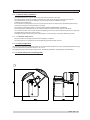
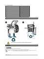
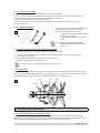
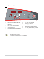
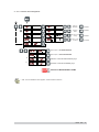
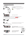
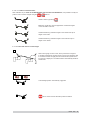
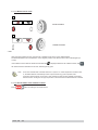
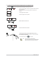
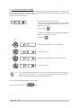
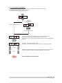
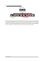
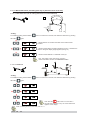
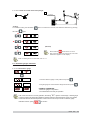
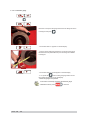
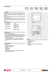
I
Instructions for use
CONTENTS
1 - GENERAL
3
1.1 - GENERAL SAFETY REGULATIONS
3
1.1.1 - STANDARD SAFETY DEVICES
3
1.2 - FIELD OF APPLICATION
3
1.3 - OVERALL DIMENSIONS (STANDARD GUARD)
3
1.4 - TECHNICAL DATA
4
2 - HANDLING AND LIFTING
4
3 - STARTUP
4
3.1 - ANCHORING
4
3.2 - ELECTRICAL CONNECTION
5
3.3 - ADAPTER MOUNTING
5
3.4 - WHEEL GUARD ASSEMBLY AND ADJUSTMENT (OPTIONAL)
5
3.5 - WD SPACER
5
4 - CONTROLS AND COMPONENTS
5
4.1 - AUTOMATIC DISTANCE AND DIAMETER GAUGE
5
4.2 - KEYBOARD AND DISPLAY
6
4.2.1 - FUNCTION MENU MANAGEMENT
7
5 - INSTRUCTIONS FOR USE OF THE WHEEL BALANCER
8
5.1 - USING THE GAUGE INSTALLED ON THE MACHINE
8
5.1.1 - DATA SETTING
8
5.2 - AUTOMATIC PRESETTING
8
5.2.1 - STEEL OR ALUMINUM WHEEL RIMS. SPRUNG COUNTERWEIGHTS
8
5.2.1.1 - STATIC & COMBINED MODES
9
5.2.2 - RIMS WITH INTERNAL COUNTERWEIGHT
9
5.3 - MEASUREMENT RESULT
10
5.4 - RECALCULATION OF THE UNBALANCE VALUES
10
5.5 - EXACT POSITIONING OF THE ADHESIVE WEIGHT BY MEANS OF THE GAUGE
WITH CLIPS
11
5.6 - SPLIT FUNCTION (HIDDEN WEIGHT)
12
5.7 - OUT OF BALANCE OPTIMIZATION
13
5.8 - AUTOMATIC MINIMISATION OF STATIC UNBALANCE
14
6 - SET-UP
15
6.1 - AUTODIAGNOSTICS
15
6.2 - AUTOCALIBRATION
15
6.3 - MANUAL DIMENSION PRESETTING (use only in particular cases or for test)
16
6.3.1 - STEEL WHEEL RIMS (use for setting dimensions in AUTOCALIBRATION)
16
6.3.2 - ALUS RIMS
16
6.3.2.1 - ALUS VARIANT WITH INSIDE CLAMP WEIGHT
17
6.4 - AUTOMATIC GAUGES CALIBRATION
17
6.4.1 - RIM DISTANCE GAUGE
17
6.4.2 - DIAMETER GAUGEE40 MM
18
7 - ERRORS
19
7.1 - INCONSISTENT UNBALANCE READINGS
20
8 - ROUTINE MAINTENANCE
20
8.1 - REPLACING THE PROTECTION FUSES
20
I 0615 GB - 1
I 0615 GB - 2
1 - GENERAL
► 1.1 - General safety regulations
The wheel balancer may only be used by duly authorized and trained personnel.
The wheel balancer must not be used for purposes other than those described in the instruction manual.
The wheel balancer must not be modified in any way except for those modifications made
explicitly by the manufacturer.
Do not remove the safety devices. Any work on the machine must be carried out by specialised personnel only.
Avoid using strong jets of compressed air for cleaning.
Use alcohol to clean plastic panels or shelves (AVOID LIQUIDS CONTAINING SOLVENTS).
Before starting the wheel balancing cycle, make sure that the wheel is securely locked on the flange.
The machine operator must not wear clothes with flapping parts. Do not allow unauthorized personnel to approach
the wheel balancer when the cycle is running.
Avoid placing objects in the base which could impair the correct operation of the wheel balancing machine.
► 1.1.1 - Standard safety devices
Stop push button for stopping the wheel under emergency conditions.
The wheel guard is not compulsory since the balancing speed is less than 100 min-1.
► 1.2 - Field of application
The machine is designed for balancing wheels of cars, light commercial vehicles or motorcycles weighing less than 75 kg.
It can be operated in a temperature range of 0° to + 45° C.
The following functions are provided: ALUS; SPLIT; Unbalance optimisation; Autodiagnostics; Autocalibration.
► 1.3 - Overall dimensions (standard guard)
1
I 0615 GB - 3
► 1.4 - Technical data
Single-phase power supply
115 / 230 V - 50/60 Hz
Protection class
IP 54
Max. power absorbed
0,8 Kw
Balancing speed
< 100 min-1
Cycle time for average wheel (14 kg)
6-8 seconds
Max. resolution of measurement
1 gram
Position resolution
± 1.4 °
Average noise
< 70dB (A)
Rim-machine distance
0 - 265 mm
Rim width setting range
1.5” - 20” or 40 - 510 mm
Diameter setting range
10” - 30” or 265 - 765 mm
2 - HANDLING AND LIFTING
2
2a
NOTE: DO NOT LIFT THE WHEEL BALANCER USING OTHER GRIPS .
3 - STARTUP
► 3.1 - Anchoring
The machine can operate on any flat non resilient floor.
Make sure that the machine rests solely on the three support points provided (Fig.2a).
NOTE: If possible, it is advisable to anchor to the floor using relative mounting feet (see fig. 2a) in the
event of continual use with wheels weighing over 35 Kg.
I 0615 GB - 4
► 3.2 - Electrical connection
The machine is supplied with a single-phase mains cable plus earth (ground).
The power supply voltage (and mains frequency) is indicated on the machine identification plate and cannot be
changed. Connection to the mains must always be made by expert personnel.
The machine must not be set up without proper earthing.
Connection to the mains should be through a slow acting safety switch rated at 3 A (230V) or 8 A(115 V).
See enclosed diagram.
► 3.3 - Adapter mounting
The wheel balancer is supplied complete with cone
adapters for fixing wheels with a central hole.
3
Other optional adapters can be mounted:
a. Remove the threaded end-piece A after
unscrewing the screw B.
b. Mount the new adapter (see attached
sheets).
NOTE: CAREFULLY CLEAN THE COUPLING
SURFACES BEFORE PERFORMING ANY
OPERATION.
► 3.4 - Wheel guard assembly and adjustment (optional)
1. Fasten the components to the base as illustrated in specific exploded view.
2. The position of the wheel guard when closed can be adjusted with relative screw accessible at the back.
Correct position is horizontal.
3. Check that the microswitch is held down when the guard is closed.
4. Adjust the angular position of microswitch control.
Note: Do not lean on the guard during the wheel balancing cycle.
► 3.5 - WD spacer
When balancing very wide wheels (9”), there is not enough space to turn the distance gauge. To move the wheel
away from the machine side, fit the WD spacer on the flange body and secure it with the standard issue nuts. When
centring the wheel with cone from the inside, mount the DC spacer to obtain spring thrust.
DC
3a
WD
Cone
Spring
4 - CONTROLS AND COMPONENTS
► 4.1 - Automatic distance and diameter gauge
Allows automatic measurement of the distance from the machine and the wheel diameter at the counterweight
application point. The same gauge can be used to position the counterweights correctly inside the wheel, using the
specifi c function that suggests the position memorised during measurement inside the rim.
I 0615 GB - 5
► 4.2 - Keyboard and display
4
1
2
18
9
8
3
13
3-4
5
6
7
8
9
10
14
15
11
16
12
4
5
1-2
17
8
6
7
Digital readouts, AMOUNT OF UNBALANCE,
inside/outside
Digital readouts, POSITION OF UNBALANCE,
inside/outside
Inside correction mode selection button
Indicators, correction mode selected
Outside correction mode selection button
Special function indicators
Manual WIDTH/DISTANCE/DIAMETER setting
buttons and MENU selection
10
11
12
13
14
15
16
17
18
Push button, FUNCTION MENU
Balancing cycle stop button
Balancing cycle start button
Position repeater push button
Push button, SPLIT (unbalance resolution)
MENU selection confirmation pushbutton
Push button, unbalance reading < 5 g (.25 oz)
Unbalance optimization selection pushbutton
Grams/ounces selection pushbutton
Press buttons only with your fingers.
Do not use the counterweight grippers or other pointed objects.
I 0615 GB - 6
► 4.2.1 - Function menu management
mm/inch
diameter
CONFIRM
mm/inch
width
CONFIRM
start from guard
closing
CONFIRM
approx. -5 g or
0.1-0.25 oz
CONFIRM
See chapter on AUTODIAGNOSTICS
See chapter on AUTOCALIBRATION
*
Calibration of automatic RIM DISTANCE gauge
*
Calibration of automatic DIAMETER gauge
RETURN TO MEASUREMENT FRAME
* N.B.: If such indications fail to appear, contact Technical Service.
I 0615 GB - 7
5 - INSTRUCTIONS FOR USE OF THE WHEEL BALANCER
► 5.1 - Using the gauge installed on the machine
► 5.1.1 - Data setting
5
For clamp weights, use the gauge in the top position A.
For adhesive weights, use the gauge as preferred in top position A
or bottom position B.
POS. A
Note:
Always use the round part of the striker plate
resting on the rim.
POS. B
5a
Indication of gauge in movement
► 5.2 - Automatic presetting
The machine automatically detects the correct balancing program for steel and aluminium rims (ALUS).
The counterweight position proposed may be changed using the two
/
buttons.
► 5.2.1 - Steel or aluminum wheel rims. Sprung counterweights
5b
5c
Pull out the gauge as far as the inner edge of the rim. Hold it in this
position until the symbol shown in Fig. 5d is displayed.
5d
Indication of dimensions acquired
Return the gauge to rest position. The machine has automatically
detected DISTANCE + DIAMETER and goes to MANUAL WIDTH
SETTING.
b
- The nominal width is normally stamped
on the rim; if not, proceed to measure
dimension “b” with the calibre gauge
(supplied as standard).
I 0615 GB - 8
5e
► 5.2.1.1 - Static & combined modes
After calibration as per STEEL OR ALUMINUM WHEEL RIMS. SPRUNG COUNTERWEIGHTS, it is possible to modify the
/
position of the correction weights using the
buttons.
STATIC: Select by pressing
Balancing of light alloy rims with application of adhesive weights
on the shoulders of the rims.
Combined balancing: adhesive weight on the outside and clip-on
weight on the inside.
Combined balancing: adhesive weight on the inside and clip-on
weight on the outside.
► 5.2.2 - Rims with internal counterweight
6
Slide out the gauge on the LH side, at the point where a weight is
to be fitted. Wait until the symbol shown in Figure 5d is displayed. Pull
it out further towards the right plane and wait until the symbol shown
in Figure 6a is displayed. The wheel balancer automatically identifi es
ALUS mode.
6a
Counterweight position automatically suggested.
can be used to set the alternative position indicated.
I 0615 GB - 9
► 5.3 - Measurement result
7a
Inside correction
7b
Outside correction
After performing a balancing spin, the amounts of unbalance are shown on the digital readouts.
The illuminated LEDs 3 and 4 indicate the correct angular position of the wheel to mount the counterweights (12
o’clock).
If the unbalance is less than the threshold value selected,
is displayed instead of the unbalance value; with
the values below the threshold can be read, selected gram by gram.
Note : in the case of wheels with a diameter less than or equal to 13” and at temperature conditions near
0°, the wheel balancer automatically inserts a special measuring cycle composed of two
successive measurements. The accuracy of the unbalance values and the reliability of the wheel
balancer remain unchanged. This type of operation is reset each time the wheel balancer is started.
► 5.4 - Recalculation of the unbalance values
Press
I 0615 GB - 10
after new setting of the measurement.
► 5.5 - Exact positioning of the adhesive weight by means of the gauge with clips
- Press the button
if using the correction method with weights on the inside of the rim.
- Fit the correction weight in the specifi c gauge seat with the adhesive
part facing upwards
- bring the wheel into correct angular position for the plane to be
corrected.
- Pull the gauge further outwards.
- Return the gauge to the rest position.
INSIDE CORRECTION POSITION
OUTSIDE CORRECTION POSITION
8
- rotate the gauge until the correction weight adheres to the rim
- the fact that the weight application position is no longer vertical (Fig.
8) is automatically compensated
- to cancel this function, press
button again.
N.B. : It is not possible to put automatically
the correction weight in the Fig.5 POS. B position;
always rotate the rim in Fig.5 POS.A upwards.
I 0615 GB - 11
► 5.6 - SPLIT function (hidden weight)
The SPLIT function is used to position the adhesive weights behind the wheel spokes so that they are not visible. This
function should be used only in the case of static unbalance or where the hidden adhesive weight is to be applied on the
outside. Input the wheel dimensions and do a spin.
Start the SPLIT function as follows:
Example of display prior to SPLIT function
- Place the wheel in the outside unbalance correction position.
- Set one of the top spokes (preferably the one to the left of the
unbalance) to 12 o’clock.
- Press the button
- Follow the UP/DOWN indication of the positioning LEDs and
set the second top spoke to 12 o’clock.
- Press button
15
- Set the first split unbalance to correction position 1
30
15
30
- Correction position 1
15
30
- Set the second split unbalance to correction position 2
30
15
N.B.:
- Correction position 2
If error 24 is displayed, repeat the SPLIT function ensuring that the minimum distance between the
spokes is greater than 18 degrees. If error 25 is displayed,repeat the split function ensuring that the
maximum distance between the spikes is smaller than 120 degrees.
To return to normal unbalance display, press any button.
To carry out a new spin, press the
I 0615 GB - 12
button.
► 5.7 - Out of balance optimization
- This function serves to reduce the amount of weight to be added in order to balance the wheel
- It is suitable for static unbalance greater than 30 g.
- It improves the residual eccentricity of the tyre.
No previous
unbalance
measurement
Unbalance already measured
unbalance measurement
- With a piece of chalk make a reference mark on the flange and the rim
- With the aid of a tyre remover, turn the tyre on the rim by 180°
- Refit the wheel in such a way that the reference marks on the rim and the flange
coincide.
- RH display: percentage reduction value
- LH display: actual static unbalance value which can be reduced by rotation
TYRE
POSITION
- Mark the two positions of the rim and tyre, and turn the tyre on the rim until the
positions correspond in order to obtain the optimization on the display.
RIM
POSITION
CANCEL OPTIMISATION IN ANY PHASE.
I 0615 GB - 13
► 5.8 - Automatic minimisation of static unbalance
Initial unbalance
Phase shift
Possible approximations
static residue
With traditional wheel
balancer
static residue
static residue
static residue
Choice with minimum
static unbalance
This program is designed to improve the quality of balancing without any mental effort or waste of time by the operator.
In fact, using the normal weights available on the market (pitch of 5 in every 5 g) and applying the two counterweights
which a conventional wheel balancer rounds to the nearest value, a residual static unbalance of up to 4 g may result.
The damage of such approximation is emphasized by the fact that static unbalance is the cause of most disturbances
on vehicles. This new function automatically indicates the optimum entity of the weights to apply by approximating
them in an “intelligent” way according to their position in order to minimize residual static unbalance.
I 0615 GB - 14
6 - SET-UP
6.1 - Autodiagnostics
Performs tests useful for maintenance staff.
► 6.2 - Autocalibration
For autocalibration proceed as follows:
1. Fit a wheel with steel rim of average dimensions on the shaft. Example 6” x 14” (± 1”)
2. Set the exact dimensions of the wheel mounted.
SETTING INCORRECT DIMENSIONS WILL RESULT IN THE MACHINE NOT BEING PROPERLY CALIBRATED AND HENCE ALL THE
SUBSEQUENT MEASUREMENTS WILL BE INCORRECT UNTIL A NEW AUTOCALIBRATION IS PERFORMED WITH THE CORRECT
DIMENSIONS!!
- Perform a spin under normal conditions.
- Add a 60 g. sample weight (2.00 oz) on the outside in any angular
position.
- Shift the sample weight from the outside to the inside keeping the
same angular position.
- Turn the wheel until the sample weight is in the 12 o’clock position.
END OF AUTOCALIBRATION
CANCEL AUTOCALIBRATION IN ANY PHASE.
I 0615 GB - 15
► 6.3 - Manual dimension presetting (Use only in particular cases or for test)
► 6.3.1 - Steel wheel rims (use for setting dimensions in AUTOCALIBRATION)
9
b
a
d
- Setting:
To enable the setting, hold the button
the button
down for more than 3 seconds, then select the dimension by pressing
again.
- Set the distance “a” between the inside of the wheel and the
machine
- Set the nominal width, normally indicated on the rim, or measure the
width “b” using the caliper gauge supplied (see fig. 5e).
- Set the nominal diameter “d” indicated on the tyre.
N.B.: This setting is also valid for the correction
modes indicated at “STATIC & COMBINED MODES”.
dI
dE
10
► 6.3.2 - ALUS rims
0 gauge
aI
aE
- Setting:
To enable the setting, hold the button
the button
down for more than 3 seconds, then select the dimension by pressing
again.
Note: Hold the
button down for more than 2
seconds when the value of any one of the dimensions
appears on the display.
Note: not setting dE as it is automatic, dE = dI - 1”.
I 0615 GB - 16
dI
► 6.3.2.1 - ALUS variant with inside clamp weight
11
dE
0 gauge
aI
aE
- Setting:
To enable the setting, hold the button
the button
down for more than 3 seconds, then select the dimension by pressing
again.
(Nominal)
Note: Hold the
button down for more
than 2 seconds when the value of any one of the
dimensions appears on the display.
Note: not setting dE as it is automatic, dE = dI - 2”.
6.4 - Automatic gauges calibration
► 6.4.1 - Rim distance gauge
- Leave the distance gauge in rest position and press
- Bring the gauge in contact with the flange surface and press
CORRECT CALIBRATION
- Return the gauge to rest position.
- The wheel balancer is ready for operation.
N.B.: In the event of errors or faulty operation, the writing “r.P.” appears on the display : shift the gauge
to the rest position and repeat the calibration operation exactly as described above. If the error persists,
contact the Technical Service Department. In the event of incorrect input in the rim distance gauge
calibration function, press
to cancel it.
I 0615 GB - 17
► 6.4.2 - Diameter gauge
E40 mm
Place the round part of the gauge terminal on the flange as shown
in the figure and press
.
- The number 289 ± 3° appears on the left display .
- Turn the gauge downward position the round part of the gauge
terminal at 40 mm (radial distance) from the flange as indicated
in the figure.
40
mm
40
mm
- The number 289 ± 3° should appear on the left display.
- If not, press the
button holding the gauge still at 40 mm:
the number 289 appears on the left display.
- Return the gauge to rest position.
In the event of incorrectly accessing the diameter gauge
calibration function, press
I 0615 GB - 18
to cancel it.
7 - ERRORS
During machine operation there may be various causes of malfunctioning which, if detected by the microprocessor,
are indicated on the display:
ERRORS CAUSES
CONTROLS
Black
The wheel balancer does not come on.
1.
2.
3.
Check proper connection to the mains.
Check and if necessary replace the fuses on the power board.
Replace the computer board.
Err. 1
No rotation signal.
1.
2.
Check belt tautness.
Check functioning of the phase generator and, in particular, the
reset signal.
Replace the phase generator.
Replace the computer board.
3.
4.
Err. 2
Too low speed during measurement.
During the unbalance measurement
revolutions, the wheel speed has fallen to
below 42 rpm.
1.
Too high unbalance.
1.
2.
3.
4.
2.
3.
4.
Err. 3
5.
Check that a vehicle wheel has been mounted on the wheel
balancer.
Check belt tautness.
Check functioning of the phase generator and, in particular, the
reset signal.
Replace the computer board.
Check the wheel dimension setting.
Check the sensor connections.
Run the machine calibration function.
Mount a wheel with a more or less known unbalance (less than 100
grams) and check the machine response.
Replace the computer board.
Err. 4
Rotation in opposite direction.
After pressing [START], the wheel
starts turning in the opposite direction
(anticlockwise).
1.
Verify the connection of the UP/DOWN - RESET signals on the
phase generator.
Err. 5
Guard open
The [START] pushbutton was pressed
without first closing the guard.
1.
2.
3.
4.
Reset the error.
Close the guard.
Verify the function of the protection uSwitch.
Press the [START] button.
Err. 7 /
Err. 8 /
Err. 9
NOVRAM parameter read error
1.
2.
3.
4.
5.
Repeat machine calibration
Shut down the machine.
Wait for at least ~ 1 min.
Restart the machine and check proper functioning.
Replace the computer board.
Err. 11
Too high speed error.
The average spinning speed is greater than
240 rpm.
1.
2.
Check if there is any damage or dirt on the timing disc.
Check functioning of the phase generator and, in particular, the
reset signal.
Replace the computer board.
3.
Err.14/
Err.15/
Err.16/
Err.17/
Err. 18/
Err. 19
Unbalance measurement error.
1.
2.
3.
4.
5.
Check functioning of the phase generator.
Check the sensor connections.
Check the machine earthing connection.
Mount a wheel with a more or less known unbalance (less than 100
grams) and check the machine response.
Replace the computer board.
Err.21
Motor on for more than 15 seconds.
1.
2.
3.
Check functioning of the phase generator.
Check the connections on the power board.
Replace the computer board.
Err.22
Maximum number of spins possible for
the unbalance measurement has been
exceeded.
1.
Check that a vehicle wheel has been mounted on the wheel
balancer.
Check belt tautness.
Check functioning of the phase generator and, in particular, the
reset signal.
Replace the computer board.
2.
3.
4.
Err. 24
Distance between the spokes smaller
than 18 degrees.
1.
2.
Err. 25
Distance between the spokes greater
than 120 degree
1.
2.
The minimum distance between the spokes where to split the
unbalance must be greater than 18 degrees
Repeat the SPLIT function increasing the distance between the
spokes.
The minimum distance between the spokes where to split the
unbalance must be smaller than 120 degrees
Repeat the SPLIT function increasing the distance between the
spokes.
I 0615 GB - 19
Err.32/
Err.33/
Err.34/
Err.35/
Err.36/
Err.37
Errors related to test functions of the wheel
balancer.
1.
Cancel the error and continue using the wheel balancer as normal.
► 7.1 - Inconsistent unbalance readings
It may occur that after balancing a wheel, when removing it from the wheel balancer and then remounting it, the
wheel is not balanced.
This is not the result of an incorrect indication by the machine, but only of incorrect mounting of the wheel on the
flange, i.e. in the two mountings the wheel has assumed a different position with respect to shaft axis of the wheel
balancer. If the wheel has been mounted on the flange with screws, it may be that the screws have not been tightened correctly in gradual criss-cross manner one after the other, or (as often occurs) holes have been drilled in the
wheel with too wide tolerances.
Small errors, up to 10 grams (0.4 oz), are to be considered normal in wheels locked with a cone: the error is normally
greater for wheels locked with screws or studs.
If, after balancing, the wheel is still unbalanced when refitted on the vehicle, this could be due to the unbalance of
the brake drum or very often is due to the screw holes in the rim and the drum drilled with too wide tolerances. In this
case a readjustment would be advisable using the wheel balancer with the wheel mounted.
8 - ROUTINE MAINTENANCE
Before carrying out any operation on the machine, cut the power supply to the machine.
► 8.1 - Replacing the protection fuses
A protection fuse is fitted on the power board, accessible by dismantling the weight shelf (see Exploded Drawings). If
fuses require replacement, use ones with an identical current rating.
If the fault persists, contact Technical Service.
NONE OF THE OTHER MACHINE PARTS REQUIRE MAINTENANCE.
I 0615 GB - 20