1
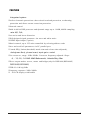
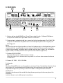
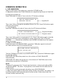
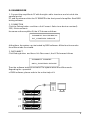
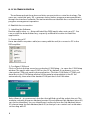
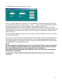
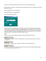
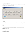
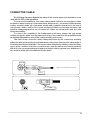
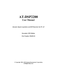
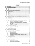
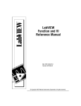
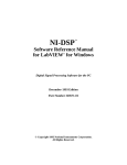
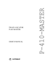
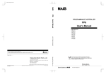
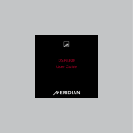
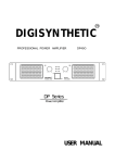
R
DIGISYNTHETIC
INTEGRATED DSP POWER AMPLIFIER
E SERIES PROFESSIONAL AMPLIFIER
DSP4800
DSP3200
DSP2240
DSP1800
DSP1400
DSP2200
DSP1200
DSP4800E
DSP3200E
DSP2240E
DSP1800E
DSP1400E
DSP2200E
DSP1200E
USER MANUAL
IMPORTANT SAFETY INSTRUCTION
WARNING
When using electric products, basic precautions should always be followed:
1. Read all the SAFETY INSTRUCTIONS before using the product.
2. This product must be earthed. If it has malfunction or breaks down, grounding provides a path of
least resistance for electric current to reduce risk of electric shock.
This product is equipped with a cord having an equipment-grounding conductor and a grounding plug.
The plug must be plugged into an appropriate outlet that is properly installed and earthed in
accordance
with all local codes and ordinance.
DANGER - Improper connection of the equipment-grounding conductor can result in a risk of
electric shock. Check with a qualified electrician or serviceman if you are in doubt as to whether the
product is properly grounded. Do not modify the plug provided with the product - if it will not fit the outlet,
have a proper outlet installed by a qualified electrician.
3. To reduce the risk of injury, close supervision is necessary when the product is used near children.
4. Do not use this product near water - for example, near a bathtub, washbowl, kitchen sink, in wet
basement or near a swimming pool or the lake.
5. This product may be capable of producing sound levels that could cause permanent hearing loss.
Do not operate for a long period of time at high volume level or at a level that is uncomfortable. If you
experience any hearing loss or ringing in the ears, you should consult an audiologist.
6. This product should be located so that its location or position does not interfere with its proper
ventilation.
7. This product should be located away from heat sources such as radiators, heat registers or other
products that produce heat.
8. The product should be connected to a power supply only of the type described on the operating
instructions or as marked on the product.
9. This product may be equipped with a polarized line plug (one blade wider than the other). This is a
safety feature. If you are unable to insert the plug into the outlet, contact an electrician to replace your
obsolete outlet. Do not defeat the safety purpose of the plug.
10. The power-supply cord of the product should be unplugged from the outlet when left unused for a
long period of time. When unplugging the power-supply cord, do not pull on the cord, but grasp it by
the plug.
11. Care should be taken so that object do not fall and liquid are not spilled into the enclosure through
openings
12. The product should be serviced by qualified service personnel when:
A. The power-supply cord or the plug has been damaged;
B. Objects have fallen, or liquid has been spilled into the product;
C. The product has been exposed to rain;
D. The product does not appear to operate normally or exhibits a marked change in performance;
E. The product has been dropped or the enclosure damaged.
13. Do not attempt to service the product beyond that described in the user-maintenance instructions.
All other servicing should be referred to qualified service personnel.
WARNING - Do not place objects on the product's power cord or place it in a position where
anyone could trip over, walk on or roll anything over it. Do not allow the product to rest on or to be
installed
over power cords of any type. Improper installations of this type create the possibility of fire hazard and/
or personal injury.
1
Installation & operating instruction
Mains power connection.
Before connecting the amplifier to the mains power socket, make certain that the voltage
corresponds with that indicated on the rear of the unit (an allowance of 10% is acceptable).
Before connecting the power cable to the mains, always make certain that it is not
damaged and that there are no bare wires, always connect the power cable to the
amplifier before switching it on and only remove the cable after switching it off.
Switching on and off.
In an audio system, it's always better to switch power amplifiers on last and off first.
Remember to switch off the amplifier before connecting it to or disconnecting it from other
units and to switch always on first the mixer and then the amplifier: in this manner, peaks
which are annoying and sometimes dangerous particularly for the loudspeakers enclosures
are avoided. It is normal for the LEDs to light up for a few moments when switching on.
Handling.
Do not force knobs and connectors, as they could be damaged if treated with excessive
force.
Connections and prevention of possible interference.
Avoid installing your equipment near radios, televisions, etc., since they could cause noisy
disturbance. When connecting the other units in your sound system, watch out for to socalled earth-loops, which can cause hum: in the event of interference, try using the EARTH
switch on the amplifier's rear panel.
Connector cables.
To connect the amplifier to the mixer, always make certain to use only signal cables
(screened cables made up of two wires plus a braid screen), not power cables (speaker
cables, normally made up of two wires, usually with a greater cross-section): to connect the
amplifier to the loudspeaker enclosures, always use power cables, not signal cables, as in
the latter case in fact, the power from the amplifiers would be partially disperse because of
the cable's smaller cross-section.
Take care of the connector cables. Always hold them by the connectors, avoiding pulling
the wire and avoid knots and twists when coiling them: this gives the advantage of
increasing their life and reliability.
Air circulation for cooling.
Amplifier's correct cooling is ensured by an internal fan, the speed of which is controlled
by a special sensor (the speed is proportional to output power and therefore the
temperature generated):remember never to block the air vents located on the unit's sides in
any way: the air necessary for cooling passes through these.
If the amplifier is kept in a flight-case during use, make certain that it has sufficient openings
at both the amplifier's air vents. Avoid locating it very small spaces which don't allow correct
air circulation.
2
FEATURE
Integrated system
? Perfect electronic protections: short circuit/overload protection, overheating
protection and direct current excursion protection.
? Network control
? Built-in 48-bit DSP processor and dynamic range up to 116dB, 48kHz sampling
rate A/D, D/A,
? Low noise and lower distortion
? Well-designed signal generator: sin wave and white noise
? S/PDIF input/output ( option)
? Matrix control, up to 255 units controlled by selecting address code
? Save and recall all parameters via PC parallel port
? 3 bands PEQ, limiter(threshold, attack time and release time adjusted),
delay(max 8ms), phase invert, input gain control
? Two crossover, range: 20Hz-20kHz. Crossover frequency adjusted. Slope:
-6, - 12, -18, -24 AND 48dB Butterworth, Linkwitz-Riley filter
? Three output modes: stereo, mono and bridge(only for DSP1400,DSP1400E,
DSP2200E,DSP1200E)
? THD+N: 0.08%@1kHz
? Frequency response: 20Hz-20kHz
? 2 20 LCD display with backlit
3
CONTROL PANEL
A. FRONT PANEL
1
5
1
3
2
5
2
4
6
3 64
1. CHA : Adjust the volume of channel A
CHA /C: Adjust the volume of channel A/C(only for DSP4800 & DSP4800E)
2. CHB : Adjust the volume of channel B
CHB /D: Adjust the volume of channel B/D(only for DSP4800 & DSP4800E)
3. INPUT INTERFACE TO PC
4. OUTPUT INTERFACE TO PC
5. 2 20 LCD DISPLAY WITH BACKLIT
6. POWER: ON/OFF
Note: Press the rotar y encoder(1,2) to switch between the CHA/B and
CHC/D.
4
B. REAR PANEL
1
CH.B IN
BA LAN CED
0d B
30 K OH M
2
OTUPUT
IMPE DANCE
CH.A IN
OHM
OHM
16
8
OH M
OH M
BAL ANC ED
4
OHM
4
OH M
0dB
PI N1+ 2: +
PI N1-1 -:
-
L I NK
CH.A OUT
CH.B OUT
+
-
LINK
POWER INPUT
+
L INK
4
-
30K OHM
PIN1 +2:
PIN1 -1-:
+
-
LIN K
SERIAL No
EARTH
A C2 30V 10%
50 6 0 Hz
5
OTU PUT
16
8
IM PED ANC E
3
1. Balanced input(odB/30kOhm): For all the models, both CHA and CHB have
one pair of balanced input with cannon connector.
2. Power output: output should be connected to the loudspeaker. The CHA/CHB
outputs of DSP series amplifier have one waterproof jack and one group of
binding post.
Note:
The rated power and the impedance load of loudspeaker or loudspeaker system
must match the amplifier(see technical specification). Please use the speaker
cable only(normally provided with one red and one black wire). Do not use the
signal cable( normally used for microphone and audio equipment).
3. Earthed ON/FLOATING
Separate the signal earth from the chassis.
Using this selector to break earth loops which can form when several units are
connected.
4. Power: AC 230V 10% 50-60Hz.
5. Air vents
Note:
The fan of the DSP series cooling system creates a flow of air with the direction from
front to back. That means the air is taken from the opening on the front and is
expelled through the opening on the front after cooling the heat sinks and
transformer.
Attention must be paid to avoid blocking these openings. And never place the
amplifier
in which there is not sufficient air circulation.
5
OPERATION INSTRUCTION
I: OFF LINE M ODE:
Switch on the power, the system accesses the OFFLINE mode.
A. Adjust the volume: turn CHA/CHB button to adjust the input level of CHA/CHB.
B. Setup the amplifier ID:
Press CHA button for about 3 seconds, the LCD shows as follows:
SET UP AMPLIF IER
DEVICE
ID
NO.#1
Amplifier ID
Then, turn CHA to change the amplifier ID from 1 to 255. Press CHA button again
and save the setting.
C. Load program
Press the CHB button for about 3 seconds, the LCD shows as follows:
LOAD
PROGRAM P :11
NO PEQ+XOVER+DELAY
Program Number
Program name
Then, turn CHA to select one program(1-11) . Press CHB button again, save the
setting and load the selected program. At the same time, the LCD shows:
LOADING ..........Several seconds later, the LOADING is finished and the system
return the menu
D. SETUP VOLUME PROTECT
Under the menu of LOAD PROGRAM , press the CHB button again for about 3
seconds and then the LCD shows as follows:
VOLUME MUTE PROTECT
AUTO MUTE:
ON
Turn the CHB button to switch on/off AUTO MUTE. Then, press the CHB button again
to save the setting.
AUTO MUTE: ON. When the power is on, the volume of CHA/CHB is MUTE
automatically.
AUTO MUTE: OFF. When the power is on, the volume of CHA/CHB comes to the
setting when power was off last time.
NOTE:
1.Among 11 programs, No.11 is not used under the online mode without PEQ,
XOVER and DELAY. The other 10 programs can be saved and recalled on the
online mode.
2. The volume is mute automatically after ever y LOAD PROGRAM.
3. When the system switches from the online mode to the offline, the system can
load the program that is saved under th online mode. At the same time, the
volume is mute automatically.
6
II: ONLINE M ODE
1. Connect the amplifier to PC with the right cable: insert one end ot cable into
parallel port of
PC and the other end into the PC REMOTE in the front panel of amplifier. Start DSP6
testing software.
2. CONNECTION
Click the Debug button and then click Connect. Select one device number(1255). If this number is
the same as the amplifier ID, the LCD shows as follows:
CONNECT SUCCESSFUL
PC_CONTROL DEVICE
At that time, the system can be tested by DSP6 software. All the functions under
the offline mode is not valid.
.
3. DISCONNECT
Click Debug button and then click Disconnect, the LCD shows as follows:
CONNECT CANCEL
MCU_CONTROL DEVICE
Then the software testing is not valid. The system return the offline mode.
Regarding the operation
of DSP6 software, please refer to the online help of it.
DIGISYNTHETIC
#1
R
R
POWE R
DSP3200
PC RE MOTE
I NPUT
48KH zSAMPLING RATE
CHA
OU TPUT
POWER
CHB
R
DSP3200
24BI T DSP STE REO POW ER AMPL IFI E R
PC REMOTE
INPUT
48KHzSAMPLI NGRAT E
CHA
OUTPUT
CHB
24BI T DSPST ERE OPOW ER AMPLI FI ER
DIGISYNTHETIC
#3
PC REMOTE
INPUT
48KHzSAMPLI NGRAT E
CHA
DIGISYNTHETIC
#2
DSP3200
24BI T DSP STE REO POW ER AMPL IFI E R
CHB
OUTPUT
POWE R
7
III. PC SOFTWARE OPERATION
The software adopts the advanced telecommunication control technology. The
user can control the gain, EQ, crossover, delay, limiter, program management etc.
through the interface software. The below introduces establish the connection and
program management operation.
A. Establish the connection
1. Installing the Software
Run the application <>. Setup will install the DSP6 application onto your PC. You
can accept the default director y, or specify a different location to install the
application.
2. Connecting a PC
Use a standard computer cable (accessor y with the unit) to connect a PC to the
DSP amplifier.
3. Configure COM port
Click on Tools in the top menu bar, and select COM Setup... to open the COM Setup
window. The application uses COM1 on the PC by default. If necessar y, you can
change the COM port used by the application. Click the COM Select: COM1 pulldown box in the COM Setup window, all the serial ports available in the PC list
automatically, then select the desired COM port and click OK button.
Select Search...to open search function that will find out all the units in the net. The
multiple units with the same Address (master ID) and different Sub Address (slave ID)
can not be identified. You can identify such units only from the Sub Address (slave
ID), please keep the Sub Address (slave ID) so that you can control such units when
connecting with PC
8
4. Establish the Communication Connect
Select Connect button to open the Connect window. Fill in the Add and/or Sub Add
to select the unit. Click Connect to go online , , Then you can adjust the amplifier s
parameters of gain,EQ, crossover, delay, compress/limit, mode etc..
The Address (main ID) is from 1 to 255 that can be setup by the user freely. The Sub
Address (slave ID) is from 1 to 65536 that is preset in the factor y and can ' t be changed.
The Sub Address will display each time the unit powers on or press the left jog-wheel
after turning on.
The unit is mute (default) if mute is selected by clicking the MUTE checkbox, otherwise
the unit gain remains.
Disconnect means the unit connecting goes out of the PC control. The unit will reload
the program automatically while disconnect. The gain will escalate gradually up to
the program gain if the program gain is not mute and AUTO MUTE is OFF (refer to SETUP
VOLUME PROTECT in amplifier manual).
NOTE:
The user must fill in Sub Add (slave ID) to connect the unit if two or above units with
the same Add (master ID). Otherwise the system would connect all the units with
the same Add (master ID) to cause communication malfunction.
If no units have the same Add (master ID), the user can connect the units without
Sub Add (slave ID) setup.
The present connect unit disconnects automatically every time connecting a
new unit.
9
Click Device button to open the Device window. The user can modify the Name of
the unit and manage the device information before connect. The maximum units
can be managed are 255. Select a device, click OK button, the device information
will be sent to the Connect window.
B. Program Management
A program can be stored in any one of the 20 available memor y locations. The
No. 21program is a default one, who can ' t be refreshed, EQ and Limiter cur ve is
smooth. No delay. The phase is zero.
Refresh: Write the current program content into the unit. The "[###]" symbol
indicates there are setup parameters in program. Vice versa.
Upload: Recall the program, and setup the program number as the current one,
mute and pass the parameters to the PC program interface.
10
File Down: Download the file stored in PC into the unit as the program.
Setup Down: Collect the current interface parameters to form a program and download into the unit.
Delete: Delete the current program.
Delete All: Delete all the programs.
Save: Store a program in PC.
The user can select the file gain in File Down mode (the parameter gain in Setup
Down mode) or mute when download the program. Such gain can be effective only
if the unit is in the offline mode and AUTO MUTE is OFF. In online mode, the unit will
download the file and recall the program when New or Open the file. If the current
program is No.21, the user can ' t New or Open the file.
Note:
All the communication states are indicated in the bottom left corner.
1 is the Add (master ID), Finish... indicates the communication (send or receive) is
completed.
Please Wait... indicates the data has not been sent out, Please wait .
Record... indicates the correct return signal is not received. Please operate again
or check the communication line.
11
1. MENU COMMAND
File menu
Open
Open an existing File of PC
Save
Save current setting to PC
Read From Memor y Read the parameters of the program
Send To Memor y
Save the value of parameters to the program
Exit
Exit PC application
Mode menu
Stereo
Stereo mode, the input and output of left and right channel is
independent
Bridge
Bridge mode, the output phase of left and right channel is reverse
mono
Mono mode, the output phase of left and right channel is same
Test menu
Sine wave
Sine wave test, generate the sine wave signal for testing the system.
Frequency range: 20Hz~20kHz
Noise
white noise test, generate the white noise signal for testing the
system
Debug menu
connect
Connect the device to PC and then controlled by PC
Disconnect
Disconnect the device away from PC
Help menu
Content
index to topics
About DSP_6
Version and the information of company
12
2. PARAMETER ADJUSTMENT
Under the main interface, click the relevant button to adjust the parameters of
Gain, PE Q, Xover , D Elay, Phase and Limiter
.
1) Gain
Click Gainbutton to set the level of the Left/right Channel.Volume Range:-60dB
to 6dB.
2) PEQ
Click "PEQ" button and then the frequency, gain, Q value and flat (on/off) of 5
band PEQ can be set.
Frequen cy range: 19.7Hz ~20.2kHz
Q value range: 0.4~128
13
3) Xover
Click the Xoverb utton and then the parameters of filter ( slope and frequency of
HPF/LPF ) can be set. The MinimumFrequency of LPF is not lower than The maximum
frequency of HPF
.
4) Delay
Click the Delay button and then the delay unit and delay time can be set. Max
delay: 8ms.
5) Phase
Click the 180 check box to
select The reverse phase
: 0 , 180 .
6) Limiter
Click the Limiter button and then the threshold, hold time, attack time an d
release time can be adjusted. Used for protecting the system
.
14
CONNECTOR CABLE
The following diagrams illustrate the wiring of the various types of sockets that can be
used with the DSP power amplifiers.
To connect the amplifier to the mixer, always make certain to use only signal cables
(screened cables made up of two wires plus a braid screen ), not power cables (speaker
cables, normally made up of two wires, usually with a greater cross-section): the use of
unscreened cables could in fact cause annoying buzzes and background noise. We
therefore always suggest the use of balanced cables for microphones and line units
whenever possible.
To connect the amplifier to the loudspeaker enclosures, always use only power
cables, not signal cables, as in the latter case in fact, the power from the amplifiers would
be partially dispersed because of the cable's smaller cross-section.
Take care of the connector cables. Always hold them by the connectors, avoiding
pulling the wire and avoid knots and twists when coiling them: this gives the advantage of
increasing their life and reliability. Check your cables periodically, making certain that they
are in good condition, that the connectors are correctly wired and contacts perfectly
efficient: in fact, many problems and setbacks (faulty contacts, ground hum, disturbance,
etc.) are due to the use of unsuitable of faulty cables.
GROU ND
Balanced cannon f emale connector
COLD (-)
HOT (+)
PC OUTPUT
15
SPECIFICATION
☆ Rack Size: 3U, Power (RMS):
-DSP4800 4×450W (8Ω); 4×700W (4Ω); Bridge:2×1300W (8Ω) 39kg
-DSP3200 2×1000W (8Ω), RMS 2×1700W (4Ω) 41kg
-DSP2240 2×850W (8Ω), RMS 2×1300W (4Ω) 39kg
-DSP1800 2×650W (8Ω), RMS 2×1000W (4Ω) 35kg
-DSP1400 2×450W (8Ω), RMS 2×700W (4Ω) BRIDGE 1300W (8Ω) 29kg
☆ R a c k S i z e: 2U, Power (RMS):
- D S P 2 2 0 0 : 2×450W (8Ω); 2×750W (4Ω); Bridge: 1300W (8Ω) 30kg
- D S P 1 2 0 0 : 2×350W (8Ω); 2×600W (4Ω); Bridge: 1000W (8Ω) 31kg
☆ Rack Size: 3U, Power (RMS):
-DSP4800E:4×450W (8Ω); 4×700W (4Ω); Bridge:2×1300W (8Ω) 39kg
- D S P 3 2 0 0 E : 2×1000W (8Ω); 2×1 700W (4Ω); 2×2100W(2Ω) 40kg
- D S P 2 2 4 0 E : 2×850W (8Ω); 2×1300W (4Ω); 2×1800W(2Ω)
37kg
- D S P 1 8 0 0 E : 2×650W (8Ω); 2×1000W (4Ω); 2×1200 (2Ω)
34kg
- D S P 1 4 0 0 E : 2×450W (8Ω); 2×700W (4Ω); 2×900W(2Ω); Bridge:1300W ( 8Ω)
30kg
☆ R a c k S i z e: 2U, Power (RMS):
- D S P 2 2 0 0 E : 2×450W (8Ω); 2×750W (4Ω); 2×1000W(2Ω); Bridge: 1300W ( 8Ω)
30kg
- D S P 1 2 0 0 E : 2×350W (8Ω); 2×600W (4Ω); 2×800W(2Ω); Bridge: 1000W ( 8Ω)
31kg
SNR
THD+N
IMD
F r e q u e n c y response
I n p u t s e n s itivity/impedance
Crosstalk
D a m p i n g f a ctor
P h a s e r e s p onse
V o l t a g e g a in
Protection
s h o r t e d p r otection
S t a n d a r d p ower
Dimension
G r o s s w e i g ht
16
>90dB
0.08%@1kHz
0.1%8?, 1kHz@1W
20-20kHz(+0,-0.5dB)
0dB(0.775Vrms)/30k?
>50dB
>500:1 @1kHz/8?
-18 ° @20Hz
+25° @20kHz
40dB@1kHz/8 ?
DC , overload, thermal and
AC110V± 10% 50-60Hz
483 ? 32? 95mm