1
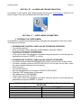
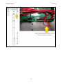
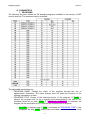
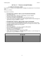
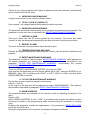
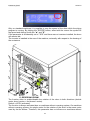
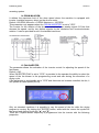
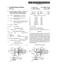
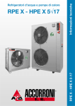
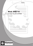
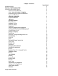
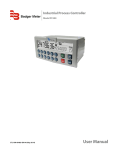
E150401X_ENG 27/07/2015 SERVICE BOOK “IM7” FOR TUMBLE DRYERS “T” MODEL SINCE SERIAL NUMBER: E201003027 WITH IM7 SOFTWARE rel. 2.20 OR HIGHER IMESA S.p.A. Via degli Olmi 22 31040 Cessalto (TV), Italia tel. +39.0421.468011 fax +39.0421.468000 www.imesa.it E150401X_ENG 27/07/2015 INDEX SECTION “A” – INTRODUCTION ........................................................................................ 4 1) CONTENTS OF THE MANUAL ................................................................................. 4 2) SAFETY RULES ........................................................................................................ 4 3) MANUFACTURER LIABILITY.................................................................................... 5 4) IM7 MICROPROCESSOR DESCRIPTION ................................................................ 6 SECTION “B” – ALARMS AND TROUBLESHOOTING ....................................................... 7 SECTION “C” – USER’S MENU PARAMETERS ................................................................. 7 1) ENTERING THE USER’S MENU ............................................................................... 7 2) PARAMETERS .......................................................................................................... 9 1. PROGRAMS .............................................................................................................. 9 2. LANGUAGE ............................................................................................................. 11 3. DATE/HOUR ............................................................................................................ 11 4. CONSUMPTION ...................................................................................................... 11 SECTION “D” – TECHNICAL PARAMETER MENU .......................................................... 12 1) ACCESS TO TECHNICAL MENU ........................................................................... 12 2) PARAMETERS ........................................................................................................ 13 1. TEMPERATURE UNIT MEASURE: ......................................................................... 13 2. TEMPERAT. OFFSET: ............................................................................................ 13 3. MAX TEMPERATURE DRYNG: .............................................................................. 13 4. WORKING HOURS MACHINE ................................................................................ 14 5. TOTAL CYCLE N° (ABSOLUT) ............................................................................... 14 6. WORKING HOURS WARNING ............................................................................... 14 7. HISTORY ALARM .................................................................................................... 14 8. REPORT ALARM..................................................................................................... 14 9. TEMPERATURE MAX REACHED ........................................................................... 14 10. RESET MAINTENANCE WARNING ........................................................................ 14 11. CYCLE FOR MAINTENANCE WARNING ............................................................... 14 12. DRUM INVERTER ................................................................................................... 14 13. REVERSING DRUM ................................................................................................ 15 14. DRUM MAX RPM .................................................................................................... 16 15. FAN INVERTER....................................................................................................... 16 16. NO WRINKLE .......................................................................................................... 18 17. MAX TIME DRYING ................................................................................................. 19 18. TEMP. HYSTERESIS HEATING ............................................................................. 19 E150401X_ENG 27/07/15 19. USER PASSWORD MODIFICATION ...................................................................... 19 20. TEC. PASSWORD MODIFICATION ........................................................................ 20 21. PARTIAL POWER ................................................................................................... 20 22. COIN BOX ............................................................................................................... 21 23. DEVICE TEST ......................................................................................................... 22 24. LOADING TEST ....................................................................................................... 23 25. ASSISTANCE PHONE............................................................................................. 23 26. P.I.D. ........................................................................................................................ 24 27. ENERGY MENU ...................................................................................................... 24 28. INITIAL COOLING ................................................................................................... 24 29. STEAM CONFIGURATION...................................................................................... 24 30. TANDEM CONFIGURATION ................................................................................... 25 31. SEGNALAZIONE PRESSOSTATO ARIA ................................................................ 25 32. FEED CONTROL ..................................................................................................... 25 33. MENU HUMIDITY .................................................................................................... 25 34. GESTIONE ALLARME TERMICHE ......................................................................... 27 3 E150401X_ENG 27/07/15 SECTION “A” – INTRODUCTION 1) CONTENTS OF THE MANUAL This manual includes all the information to make a correct service on programmers installed on IMESA’s dryers series "T". This document is written in compliance with the European rules in force. Information are addressed to the service technician, who must be sure to completely understand them before to work on the machine. This document must always be available for consultancy; in case it should be lost or damaged, ask to the manufacturer for a new one. Manufacturer is not responsible for consequences deriving from a not correct use of the new device, due to a not complete or missing reading of this document. Manufacturer reserves itself the right to modify the specification here written an the characteristics of each machine. Pictures of this document may differ form reality for some details. Technical data or drawing could be modified without any previous notice. 2) SAFETY RULES Not respecting the following instruction, may cause damages to people, things and animals. Installation and maintenance of the here described machines must be trained by authorised personnel, which knows the product and respecting the European Rules in matter of industrial machines installation. Here described tumble dryers must be used to professionally drying clothes and linen: any other use is forbidden, if not before authorized by the manufacturer. Do not dry in the machine any other different object; do not dry linen, which entered in contact with dangerous stuff like explosives, detonating explosives or inflammables. Linen entered in contact with this substances, need to be rinsed or aired before to be dried. Do not dry linen which has been soaked in substances dangerous for the operator health, like poison or cancerogenic stuff. To avoid risks of fire or explosion, do not approach to the machine with combustible or inflammable substances. Always stick to the drying instruction written on linen label. The use of this machine is forbidden to people under 14 years of age. External supplementary connection to the machine release the manufacturer from any responsibility if they are not properly done. ELECTROCUTION DANGER Service on machine’s electric system must be performed only by qualified and well trained personnel and only after electric supply to the machine is cut. Power and control board can be modified only by manufacturer’s personnel, 4 E150401X_ENG 27/07/15 otherwise the warranty condition will immediately expire. ATTENTION! Even if the main switch is in position “0”, main cables before it are under tension! OPERATOR’S PSYCHO-PHYSICAL CONDITION User of the tumble dryer must be in perfect psychophysical condition. While working assume a vertical position in front of the machine. Sudden and not controlled movement must be avoided, for example when the linen is introduced or taken out, in order to avoid dangerous impact against the machine. In case other users or other people is present, this must not be source of distraction for the operator working on the machine. While the user is working on the machine, he must not be distracted by TV, radio, etc. or being subject to any other source of distraction. ATTENTION! The above advices do not cover all possible risks. User must proceed with maximum care respecting the rules. 3) MANUFACTURER LIABILITY Instruction of this document do no replace, but only integrated, the duties coming from the safety and accident prevention rules in force. With reference to what is written in this document, the manufacturer is not responsible for: Use of the machine not in compliance with the safety and accident prevention rules in force; Not correct machine installation; Missing of a ordinary and programmed maintenance; Missing or not respect of the instruction written in the manual; Tension or supply defects; Not authorized modification to the machine. Use of the machine by not authorized people; Not correct installation of IM7 board; 5 E150401X_ENG 27/07/15 4) IM7 MICROPROCESSOR DESCRIPTION Entry into service: April 2010. Installed on: Driers "T" series Data interface: NO SW upgradeable: NO Programmable: YES Inverter communication: ANALOG and STEP Keyboard: MEMBRANE + DISPLAY Door lock: NO Coin-op release: YES Power board: NO 6 E150401X_ENG 27/07/15 SECTION “B” – ALARMS AND TROUBLESHOOTING It’s possible to see alarms and troubleshooting directly from www.imesa.it. Click the link below to login to the site and download technical manuals. SECTION “C” – USER’S MENU PARAMETERS 1) ENTERING THE USER’S MENU It’s possible to complete the programming by changing the parameters of the user’s area. To access do as follows: o o o o o STANDARD IM7 CONTROL CARD with IM7 STANDARD KEYBOARD: Turn on the machine; While the display shows "SELECT A PROGRAM", press the "MENU". On display it will appears "PASSWORD"; Type 6 times the button "START/PAUSE"; In the user’s menu the navigation is possible using the arrows to scroll through the parameters and press "ENTER" to confirm. STANDARD IM7 CONTROL CARD with IM7 COIN-OP KEYBOARD: o For serial numbers produced BEFORE E201310100, open the door of the lint filter; o For serial numbers produced LATER E201310101 do not open the lint filter, opent the electric bridge marked in the next picture. o Close the door; o Turn on the machine; o Wait for the appearance of the alarm “DOOR FILTER OPEN”. o Push the STOP button within 30 seconds; o The display shows “PASSWORD”; o Type 6 times the button “START”; o In the user’s menu the navigation is possible using the arrows to scroll through the parameters and press "ENTER" to confirm. CORRESPONDENCE BETWEEN STANDARD KEYBOARD AND COIN-OP KEYBOARD COIN-OP (SELF SERVICE) STANDARD HIGH LEFT MEDIUM ENTER LOW RIGHT START/PAUSE START STOP STOP 7 E150401X_ENG 27/07/15 8 E150401X_ENG 27/07/15 2) PARAMETERS 1. PROGRAMS The following list menu shows the 30 standard programs available in the memory of IM7 control card unit. The programs can be modified: The adjustable parameters are: o PROGRAM NAME: Change the name of the program through the use of alphanumeric characters. The name change does not entail the variation of the working temperature or time. o PROGRAM TYPE: Choice of the execution policy of the program. If "TIME" is selcted, the program will run for a specific time determined by the sum of the individual times set in each STEP. If "RESIDUAL HUMIDITY'' is selected, the program will be terminated once it reaches the required level of dryness. o N° STEP: (It appears only if "TIME" is selected as “PROGRAM TYPE“). I the programs set with “TIME” feature can be divided in one or more step. Each 9 E150401X_ENG 27/07/15 step can works with a different temperature than the others. During the program composed with multiple step it’s possible to activate the “skip” function if the parameter “FEED CONTROL” is enabled (this parameter is present only in the technical menu). . o STEP1-STEP2...STEPx: (It appears only if "TIME" is selected as “PROGRAM TYPE“). The parameter allows to select the time and the temperature on each single step. The total duration of the program is the sum of each step’s time. It’s possible to create 10 steps maximumfor each single program. o RESIDUAL HUMIDITY: (It appears only if “RESIDUAL HUMIDITY” is selected as “PROGRAM TYPE”). The parameter allows to select one of the 3 humidity levels already configured in the menu “MENU HUMIDITY”. The 3 levels of humidity available are: IRON DRY; DRY (normal dry); EXTRA DRY. o COOLING TIME: At the end of the drying process, this parameter allows to keep the fan blower and the drum rotation activated without heating. During this period, if the temperature achieves the value set in the parameter “COOLING TEMPERATURE”, the machine will stop automatically. If not reached, the cooling cycle will last for the whole time defined in this parameter. Default = 3’. o COOLING TEMPERATURE: Insert the temperature to achieve Enter the temperature to be reached during the cooling phase. If the temperature is reached within the time set in the “COOLING TIME”, the machine will automatically shut down at the end of the allotted time for this parameter. Default = 40°C. o REVERSING DRUM: On machines equipped with the reversing drum (2 motors), it allows to execute programs without inversion. The drum will rotate in one direction only. The selectable values are WITH or WITHOUT. Default = WITH o DRUM MOVEMENT TIME FORWARD: It defines the time for the clockwise rotation of the drum. Default = 40”. o DRUM MOVEMENT TIME PAUSE: It defines the pause time between the clockwise and counterclockwise rotation. Default = 5”. Do not set values lower than the default to prevent the sudden reversal of the drum inflicts on the belts or gearbox wearing. Do not set values higher than the default to avoid the burning of the linen and to ensure an uniform drying process. o DRUM MOVEMENT TIME BACKWARD: It defines the time for the counterclockwise rotation of the drum. Default = 40”. o DRUM SPEED: (It appears only if “DRUM INVERTER” is set to “YES” in the technical menu). It allows to select the rotation speed of the drum for a certain program. The rotation speed will still be editable, even if in a non-definitive way, during the working process of the machine. 10 E150401X_ENG 27/07/15 Default = 35 RPM. o FAN SPEED: (It appears only if “FAN INVERTER” is set to “YES” in the technical menu). It allows to select the fan speed for a given program. The speed will still be editable, even if in a non-definitive way, during the working process of the machine. Default = 2 o PARTIAL POWER: (it appears only if the parameter PARTIAL POWER is set to “YES” in the technical menu). The parameter is effective only for machines equipped with double electric heating remote control switch. It allows the selection of one of the two contactors, or both, to obtain the maximum heating power. During the cycle of operation it is however possible to vary the heating power used even temporary. 2. LANGUAGE It allows selection of one of the 10 languages available. 3. DATE/HOUR It allows to adjust the timing of the control board IM7. 4. CONSUMPTION View energy consumption of the machine according to the values introduced into the “ENERGY MENU" available in the technical area. 11 E150401X_ENG 27/07/15 SECTION “D” – TECHNICAL PARAMETER MENU 1) ACCESS TO TECHNICAL MENU It’s possible to complete the programming by changing the parameters of the technical area. Access is as follows: To access do as follows: o o o o o STANDARD IM7 CONTROL CARD with IM7 STANDARD KEYBOARD: Turn on the machine; While the display shows "SELECT A PROGRAM", press the "MENU". On display it will appears "PASSWORD"; Type 4 times the button "START/PAUSE" and 2 times the button “▲”; In the user’s menu the navigation is possible using the arrows to scroll through the parameters and press "ENTER" to confirm. STANDARD IM7 CONTROL CARD with IM7 COIN-OP KEYBOARD: o For serial numbers produced BEFORE E201310100, open the door of the lint filter; o For serial numbers produced LATER E201310101 do not open the lint filter, opent the electric bridge marked in the next picture. o Close the door; o Turn on the machine; o Wait for the appearance of the alarm “DOOR FILTER OPEN”. o Push the STOP button within 30 seconds; o The display shows “PASSWORD”; o Type 4 times the button “START” and 2 times “HIGH”; o In the menu the navigation is possible using the arrows to scroll through the parameters and press "ENTER" to confirm. CORRESPONDENCE BETWEEN STANDARD KEYBOARD AND COIN-OP KEYBOARD COIN-OP (SELF SERVICE) STANDARD HIGH LEFT MEDIUM ENTER LOW RIGHT START/PAUSE START STOP STOP 12 E150401X_ENG 27/07/15 2) PARAMETERS 1. TEMPERATURE UNIT MEASURE: It allows to select the temperature’s unit of measurement. The options are °C (Celsius) or °F (Fahrenheit). Default = °C. Below is a table comparing the two temperature scales. °C 0 10 15 20 25 30 °F 32.0 50.0 59.0 68.0 77.0 86.0 35 40 45 50 55 60 65 70 75 80 85 90 95.0 104.0 113.0 122.0 131.0 140.0 149.0 158.0 167.0 176.0 185.0 194.0 2. TEMPERAT. OFFSET: This parameter introduces an error, positive or negative, to the actual reading of the temperature probe. Default = 0 ° C It can distort the actual reading of the temperature probe of some degree for advance or delay the intervention of the heating. 3. MAX TEMPERATURE DRYNG: The parameter allows to set the maximum heating temperature the machine can reach. Default = 90°C. Minimum = 0°C. Maximum = 90°C. 13 E150401X_ENG 27/07/15 If there is any drying programs with higher temperature than the maximum, automatically will be lowered until the set value. 4. WORKING HOURS MACHINE Vengono trascritte le ore ed i minuti di effettivo lavoro. 5. TOTAL CYCLE N° (ABSOLUT) Sono riportati i cicli eseguiti dalla prima accensione delle macchina. 6. WORKING HOURS WARNING The parameter shows the actual working hours since the last maintenance performed. The parameter is reset each time it is activated the RESET MAINTENANCE WARNING. 7. HISTORY ALARM This menu shows the last 50 errors reported by the machine. The errors are called "events" as they are always accompanied by the date and time in which they occurred. 8. REPORT ALARM The menu stores the counting of each alarm divided by type. 9. TEMPERATURE MAX REACHED Displays the highest temperature reached by the machine with the detail of date/time and program. 10. RESET MAINTENANCE WARNING The parameter is used to clear the alarm "MAINTENANCE WARNING" which appears on the display whenever you reached the maximum amount of hours described in the parameter "CYCLE FOR MAINTENANCE WARNING". Automatically the counter "WORKING HOURS WARNING" is reset. Default = NO. To run the "RESET MAINTENANCE NOTICE" you must set "YES". After entering the parameter you will find the default value "NO", press the ENTER key (or MEDIUM), when NO is flashing push RIGHT or LEFT (HIGH or LOW) and then press ENTER (MEDIUM) to confirm. 11. CYCLE FOR MAINTENANCE WARNING Set the time counter to perform periodic maintenance. Default = 1500 (h). At the expiry of the hour set will be released the alarm "MAINTENANCE". Then perform the procedure described in paragraph "RESET MAINTENANCE WARNING". 12. DRUM INVERTER The parameter allows the activation of the inverter control for adjusting the speed of the drum. Default = NO. When "DRUM INVERTER" is set to "YES", is provided to the operator the ability to select the speed of rotation in the programming mode and also during the execution of a drying cycle. Enabling this parameter implies the appearance of the parameter "DRUM MAX RPM" inside the technical menu. During the drying phase of the machine, the display will appear as follows: 14 E150401X_ENG 27/07/15 Only on standard machines it is possible to vary the speed of the drum while the drying program is running. By clicking the "ENTER" button, select with the cursor the symbol for the speed and change it with the "▲" and "▼". If the parameter is accidentally set to "YES" and there was no inverters installed, the drum will remain idle. The inverter is installed in the rear of the machine, externally with respect to the housing of the contactors. 13. REVERSING DRUM The function allow to enable/disable the rotation of the drum in both directions (double motor: drum’s motor + fan blower’s motor). Default = WITH (activated). The function is always activated also on machines without reversing system. On machines without reversing system, the single motor for the rotation of the drum is the same motor used by the fan blower. Therefore, this parameter has no influence on machines without 15 E150401X_ENG 27/07/15 reversing system. 14. DRUM MAX RPM It defines the maximum limit of the drum speed where the machine is equipped with inverter (variable frequency drive) on the drum’s motor. Default = 80 RPM. Minimum = 0 RPM. Maximum = 100 RPM. This parameter only appears when the “DRUM INVERTER” is set to "YES". The inverter for the rotation of the drum is controlled by an analog signal 0-10Vdc that decrees the speed, and by two distinct signals for the clockwise and counterclockwise rotation. It can be provided as a kit for standard machines. 15. FAN INVERTER The parameter allows the activation of the inverter control for adjusting the speed of the fan blower. Default = NO. When "INVERTER FAN" is set to "YES", is provided to the operator the ability to select the speed of the fan blower in the programming mode and also during the execution of a drying cycle If the parameter is accidentally set to "YES" and there was no inverters installed, the fan, it will operate at rated speed (50 Hz). Only on standard machines it is possible to vary the speed of the fan while the drying program is running. By clicking the "ENTER" button, select with the cursor the symbol for the speed and change it with the "▲" and "▼". There are 4 speed whose frequency is programmed into the inverter with the following proportion: 16 E150401X_ENG 27/07/15 BLOWER’s FREQUENCY 25 Hz 30 Hz 40 Hz 50 Hz SPEED 1 2 3 4 The feature is not available for machine equipped by gas heating. The electrical integration: system for the drive of the fan has the following The inverter is installed in the rear of the machine, externally with respect to the housing of the contactors. 17 E150401X_ENG 27/07/15 16. NO WRINKLE The anti wrinkle function allows to keep the drum rotating after the end of the drying cycle with the fan off. The laundry is kept in motion to avoid the formation of permanent creases that normally are created if it garments stay for a long time inside the drum. Default = NO (not activated). If this function is activated it is necessary to introduce the following data: o END CYCLE PAUSE: It defines the time between the end of the cycle and the starting of the No Wrinkle cycle. o NO WRINKLE FORWARD: Clockwise rotation time; o NO WRINKLE PAUSE: Pause time; o NO WRINKLE BACK: Counterclockwise rotation time. o MAX TIME CYCLE: Max duration of the no wrinkle cycle. While waiting for the no wrinkle cycle to start, the display shows the following screens: 18 E150401X_ENG 27/07/15 While the no wrinkle cycle is working, the display shows the following screens: The no wrinkle cycle can be interrupted by opening the door when or otherwise by pressing the stop button. 17. MAX TIME DRYING The parameter defines the maximum time duration of drying program. Default = 99’. Minimum = 0’. Max = 999’ 18. TEMP. HYSTERESIS HEATING It defines the temperature margin for the ignition of the heating (differential). This is the difference between the set point temperature (temperature set in the program) and re-ignition of the heating during the step of thermoregulation. Default = 1 ° C. Minimum = 1 ° C. Max = 1 ° C. The value can be modified to introduce any delays in the operation of the heating. 19. USER PASSWORD MODIFICATION This menu allows to customize the password to access the user’s menu. The default "user" password is "START START START START START START" (type 6 times the key 19 E150401X_ENG 27/07/15 "START") and is also described in the user’s manual of the dryer. To change the password must be entered before the current one and then enter the new one. If the user’s password was lost, you will need to put send back the IM7 control card unit to IMESA SPA for the full reset (including further custom programs). 20. TEC. PASSWORD MODIFICATION This menu allows to customize the password to access to the technical menu. The default “technical password" is composed by 4 times the "START" and 2 times "▲" (on standard version) 4 times "START" and 2 times "HIGH" (on coin op version) and is not described in the user’s manual of machine to prevent the user can access in. To change the password must be entered before the current one and then enter the new one. If the password of the technical area was lost, you will need to put send back the IM7 control card unit to IMESA SPA for the full reset (including further custom programs). 21. PARTIAL POWER For machines equipped with electric heating it is possible to choke the installed power. The control board IM7 can manage two heating channels to unison or independently. It’s possible to install two heating contactors and connect two sets of resistors with different power levels from each other. While programming will be able to handle on every single set of three resistors to use to perform the drying (see parameter POWER PARZIALIZ. In the user menu). By activating this parameter, the display appears as follows: Only on standard machines you can change the heat output while the program is running. By clicking the "ENTER" button can be selected with the cursor the figure for the power and change it with the "▲" and "▼" keys. The electrical system of the machine is as follows (heating section): 20 E150401X_ENG 27/07/15 22. COIN BOX If set to “YES” the aspect and the behavior of the IM7 control card unit become for coin-op use. The “COIN BOX MENU” become present inside the user’s menu (6 times “START” button). The drying programs will not start if the desired cost is not reached in the program. 21 E150401X_ENG 27/07/15 Default = NO. The activation of this menu makes it difficult to navigate with a standard keyboard. The correspondence of keys becomes the following: CORRESPONDENCE BETWEEN STANDARD KEYBOARD AND COIN-OP KEYBOARD COIN-OP (SELF SERVICE) COIN-OP (SELF SERVICE) HIGH HIGH MEDIUM MEDIUM LOW LOW START/PAUSE START/PAUSE STOP STOP The menu button is not covered in the self-service version: it was replaced by the following: o Turn off the machine; o Turn on the machine and wait for the IM7card initialization; o Press STOP within 30"; o Type your password. 23. DEVICE TEST The menu allows the testing of every "device" installed in the the machinery. "Device" means any components that can be activated by the IM7 card through the relay that is attached. The screen of the "DEVICE TEST" is as follows: Using the keys “▲“ e “▼“ it’s possible to browse the various device present in the machine, while the arrows "◄" and "►" turns on and off the device. The available device that can be tested are: RELAY NAME HEATING RELAY 1 HEATING RELAY 2 FAN RELAY DAMPER OPEN RELAY DAMPER CLOSE RELAY DRUM FORWARD RELAY DRUM BACKWARD RELAY DEVICE MAIN HEATING CONTACTOR MAIN HEATIN GCONTACTOR (OPTION) (SEE PARAMETER PARTIAL POWER) FAN BLOWER CONTACTOR STEAM DAMPER OPENING * STEAM DAMPER CLOSING * CLOCKWISE ROTATION CONTACTOR COUNTERCLOCKWISE ROTATION CONTACTOR 22 E150401X_ENG RESET GAS RELAY BUZZER 27/07/15 RESET SIGNAL TO THE GAS IGNITION DEVICE** BUZZER * Only for steam heated machine. ** This chanel is not working with gas valve code: 3970VA840016 WARNING! The devices "HEATING RELAY 1" and "HEATING RELAY 2" correspond to the activation of the heating. Especially for machines equipped with electric heating, operate only for a few seconds these channels to preserve the integrity of the resistors. 24. LOADING TEST The menu allows to display the status of the “digital inputs” connected to the logic board. “Digital input” means all of the “on/off” devices as, for example, the door opening microswitch, the microswitch of the lint filter, the microswitch of the air pressure switch, the microswitches of the coin meter ... It's possible to use this menu to see if the devices are efficient and if the wiring that connects them to the IM7 logic board is intact. The menu appears as follows: With the arrows "▲" and "▼" you can browse the various inputs. Activating the input or by applying an electric bridge over the input, the display shows the variation of the status. The inputs testable are the following: NAME OF THE INPUT GAS PRESS. SWITCH FILTER CLEANING MOTOR THERMAL FAN THERMAL DOOR SWITCH TOKEN SWITCH 1 TOKEN SWITCH 2 FLAME SWITCH INPUT CONNECTED NOT CONNECTED (N.O.) PRESSURE SWITCH (N.O.) THERMAL SAFETY DEVICE OF THE DRUM (N.C. since s.n. E201003027 until s.n. E201310100 N.O. since s.n. E201310101 and later) THERMAL SAFETY DEVICE OF THE FAN BLOWER (N.C. since s.n. E201003027 until s.n. E201310100 N.O. since s.n. E201310101 and later) DOOR MICROSWITCH (N.O). PAYMENT CHANEL N° 1 (N.O.) PAYMENT CHANEL N° 2 (N.O.) BURNER CONSENSE FROM POWER UNIT (N.O.) 25. ASSISTANCE PHONE It allows you to enter a phone number that appears in the display alternating with the 23 E150401X_ENG 27/07/15 maintenance prompt (see section RESET MAINTENANCE WARNING). The phone number can be dialed only numeric characters and may coincide with the phone number of the dealer or technician. Default = not set. 26. P.I.D. Not enabled. 27. ENERGY MENU This menu allows you to set the units measurement and the values for the calculation of energy consumed by the tumble dryer. The function is applicable to all dryers, regardless of the type of heating. It will be necessary to declare the heating power (P) of the machine and the energy (E) will be calculated with the formula E = P * t, where "t" is the real activation time of the heating. By default, all parameters are set to 0.00. The calculation of the heating energy is turned off. If this function is activated it is necessary to introduce the following data: o TEMPERATURE UNIT: Select "kWh" for electric heating, "kg" for steam heating or LPG gas, "mc" for natural gas heating. o HEATING POWER 1: Type here the heating power issued by the heating pack of the machine (see the machine’s nameplate). o HEATING POWER 2: Type here the heating power issued by the second set of three resistors in the machine, if provided, or if it is enabled “PARTIAL POWER”. 28. INITIAL COOLING The function allows to activate a cooling cycle before the beginning of the programmed drying cycle. The initial cooling will be applied to all programs on IM7. 29. STEAM CONFIGURATION It allows the deactivation of the air pressure switch. The function must be activated only on machines with steam heating, or dryers that are not equipped with depression control system. Default = NO The air pressure (or vacuum) switch is placed in the rear compartment of the dryer and is connected to the electric heating pack or gas burners by means of a rubber tube. The depressor analyzes the amount of air sucked by the fan blower. The contact of the vacuum switch is normally open (N.O.), and behaves as follows: MACHINE STATUS FAN BLOWER STATUS STOP / STAND BY OFF RUNNING CYCLE ON PRESSURE SWITCH STATUS NOT ACTIVE (open contact) NOT ACTIVE (close contact) Any discrepancy with the above table is cause for alarm that will be readily displayed on the screen with the following rules: MACHINE STATUS PRESSURE SWITCH STATUS ALLARM DISPLAYED 24 ACTION E150401X_ENG 27/07/15 STAND BY NOT ACTIVE NONE STAND BY ACTIVE AIR DEPRES. CLOSE RUNNING CYCLE ACTIVE NONE RUNNING CYCLE NOT ACTIVE CHECK FILTER CLEANING CICLO APPENA AVVIATO NOT ACTIVE AIR EXHAUST THE MACHINE CAN WORK THE MACHINE CAN’T BE STARTED THE MACHINE CAN WORK CLEAN THE FILTER – VERIFY THE CLEANING OF THE EXHAUST DUCT VERIFY THE CLEANING OF THE EXHAUST DUCT AND THE AIR INLET FOR THE LAUNDRY ROOM For more information and troubleshooting about these specific alarms, see the document E140304X available on www.imesa.it. 30. TANDEM CONFIGURATION Not enabled 31. SEGNALAZIONE PRESSOSTATO ARIA With reference to the control of the air pressure switch in the section “STEAM CONFIGURATION”, you can hide the display of the message “CHECK FILTER CLEANING” by setting parameter to "YES". Default for standard machines = YES. Default for self-service machines = NO. With the parameter set to "NO", and with the “COIN BOX” set to "YES", the machine no longer displays "ALARM FILTER CLEANING" but stops the heating and keeps working without activating the buzzer. 32. FEED CONTROL This function enable the fast forward (skip function) for a drying cycle. It can be used only on multi step programs. The fast forward does not act directly on the missing minutes to the end of the program, which is already feasible in the standard features by acting on the main time counter, but will skip full blocks of minutes (called steps) defined while creating the program. The function is not active in self-service mode. The fast forward command may be given from the keyboard or from an external control device. Default = Not enabled. The options are: o DISABLED. o FFWD KEYBOARD: Enables fast forward using the "►" on the keyboard of the dryer. o FFWD EXTERNAL: Allows fast forward by closing a contact (remote button) connected between terminals 5 and 6 of CN18 connector on the IM7card. 33. MENU HUMIDITY It defines the drying level of the programs that use the moisture control. The cycle time can 25 E150401X_ENG 27/07/15 be managed automatically depending by the residual moisture to be obtained at the end of cycle. The function is possible on all dryers with IM7 with software version equal and higher than 2.11. It can be activated on all 30 programs in memory by changing the parameter "PROGRAM TYPE" setting "HUMIDITY" described in the dedicated chapter (follow the previous link). The function is not activated in the self-service configuration. The drying levels are three and are configurable at will: EXTRA DRY; o N° INTERVENTIONS = 4 o HYSTERESIS = 3°C o COOLDOWN DELAY = 5’ DRY: o N° INTERVENTIONS = 2 o HYSTERESIS = 3°C o COOLDOWN DELAY = 0’ IRON DRY: o N° INTERVENTIONS = 0 o HYSTERESIS = 10°C o COOLDOWN DELAY = 0’ The parameters which characterize the drying levels are: o N° INTERVENTIONS : Each time the heating contactor is activated for warming up the temperature of the drum. o HYSTERESIS: It’s the temperature gap, below the set point, for the reactivation of the heating. In case the parameter INTERVENTIONS is equal to zero, it becomes the temperature which, in advance on the set point, interrupts the heating. o COOLDOWN DELAY: It's the delay time imposed for the activation of the cool down. It is applied once the N° INTERVENTIONS set has been reached. Here are some examples on the operation of automatic control. Example with IRON DRY moisture level: N° INTERVENTIONS = 0 HYSTERESIS = 5°C COOLDOWN DELAY = 0’ 26 E150401X_ENG 27/07/15 Example with DRY moisture level: N° INTERVENTIONS = 1 HYSTERESIS = 5°C COOLDOWN DELAY = 10’ Example with EXTRA DRY moisture level: o N° INTERVENTIONS = 3 o HYSTERESIS = 5°C o COOLDOWN DELAY = 0’ 34. GESTIONE ALLARME TERMICHE Since serial number E201003027 up to serial E201310100 it was used exclusively the contact N.C. to indicate an overload of the motors. From serial number E201310101 is used the N.O. contact to indicate an overload. The contact N.C. is now used to interrupt the power supply to the coil of the contactors. Default = N.C. If the following error appears at the first starting of the control card unit, proceed as described: Press the button MENU (on standard machines) or the button STOP (on coin-op machine) within 30” since the switching on of the display. 27 E150401X_ENG 27/07/15 It will appear the screen for the password entry. Type 4 times the “START/PAUSE” button and 2 times “▲“ (on standard machine) or type 4 times “START” and 2 times “HIGH” (on coin-op machines). Search for parameter “GESTIONE ALLARME TERMICHE” and set N.C. on machine produced before the serial number E201310101, for later serial number set N.O. 28