1
1
8VHU
V0DQXDO
,&3&RQWUROOHUVRIWKH*'7516HULHV
%LW3&,)LEUH&KDQQHO
5$,'&RQWUROOHUV
VW(GLWLRQ
&RS\ULJKW
,&3YRUWH[&RUSRUDWLRQ
:HVW9DQ%XUHQ6WUHHW
3KRHQL[$=86$
,&3YRUWH[&RPSXWHUV\VWHPH*PE+
)DOWHUVWUDVVH
)OHLQ*HUPDQ\
$OO5LJKWVDQG&KDQJHV5HVHUYHG
2
3
&RQWHQWV
V
2
2YHUYLHZ
3DUW
W,,
&KDSWHU$
&KDSWHU%
&KDSWHU&
*HQHUDO,QIRUPDWLRQ
+DUGZDUH,QVWDOODWLRQ
4XLFN6HWXS
3DUW
W,,,,
&KDSWHU'
&KDSWHU(
&KDSWHU)
&KDSWHU*
&KDSWHU+
&KDSWHU,
8VLQJ0LFURVRIW06'26
:LQGRZV[
8VLQJ1RYHOO1HW:DUH
8VLQJ:LQGRZV17
8VLQJ/,18;
8VLQJ6&281,;
8VLQJ8QL[:DUH
3DUW
W,,,
,,,
&KDSWHU&KDSWHU.
&KDSWHU/
7KH*'70213URJUDP
7KH,&35$,'1DYLJDWRU
$SSHQGL[
The following chapters are part of a PDF-document which is located in
a corresponding directory on the ICP System CDROM:
8VLQJ,%026Y[
8VLQJ,QWHUDFWLYH81,;
*'76(783LQ'HWDLO
4
/LPLWHG
G:
:DUU
UUD
DQW\
,&3YRUWH[&RUSRUDWLRQ,&3YRUWH[JXDUDQWHHVWKDWWKLVSURGXFWLVIUHHIURPGHIHFWVLQPDWHULDODQG
ZRUNPDQVKLS6XEMHFWWRWKHFRQGLWLRQVDQGOLPLWDWLRQVVHWIRUWKEHORZ,&3YRUWH[ZLOODWLWVRZQ
RSWLRQHLWKHUUHSDLURUUHSODFHDQ\SDUWRIWKLVSURGXFWZKLFKSURYHVWREHGHIHFWLYHE\UHDVRQVRI
LPSURSHUZRUNPDQVKLSRUPDWHULDOV3DUWVXVHGWRUHSDLUSURGXFWVRUUHSODFHPHQWSUR GXFWVZLOOEH
SURYLGHGE\,&3YRUWH[RQDQH[FKDQJHEDVLVDQGZLOOEHHLWKHUQHZRUUHIXUELVKHGWREHIXQFWLR Q
DOO\HTXLYDOHQWWRQHZ
7KLVZDUUDQW\GRHVQRWFRYHUDQ\GDPDJHWRWKLVSURGXFWZKLFKUHVXOWVIURPDFFLGHQWDEXVHPL V
XVHQDWXUDORUSHUVRQDOGLVDVWHU$FWVRI*RGRUDQ\XQDXWKRUL]HGGLVDVVHPEO\UHSDLURUPRGLILF D
WLRQ7KHGXUDWLRQRIWKLVZDUUDQW\LVRQH\HDUIURPWKHGDWHRIRULJLQDOUHWDLOSXUFKDVH
:DUU
UUD
DQW\
\&
&ODLP
P5
5HTXLUHPHQWV
7RREWDLQZDUUDQW\VHUYLFHUHWXUQWKHGHIHFWLYHSURGXFWIUHLJKWSUHSDLGDQGLQVXUHGWR\RXUORFDO
DXWKRUL]HG,&3YRUWH[GHDOHURUGLVWULEXWRURUWR,&3YRUWH[&RUSRUDWLRQ:HVW9DQ%XUHQ
6WUHHW3KRHQL[$=3OHDVHQRWHWKHIROORZLQJ<RXPXVWLQFOXGHWKHSURGXFWVHULDOQXPEHU
DQGD
GHWDLOHGGHVFULSWLRQRIWKHSUREOHP\RXDUHH[SHULHQFLQJ<RXPXVWDOVRLQFOXGHSURRIRIWKHGDWHRI
RULJLQDOUHWDLOSXUFKDVHDVHYLGHQFHWKDWWKHSURGXFWLVZLWKLQWKHZDUUDQW\SHULRG
,I\RXQHHGWRUHWXUQWKHSURGXFWWR,&3YRUWH[\RXPXVWILUVWREWDLQD5HWXUQ0DWHULDO$XWKRUL]DWLRQ
50$QXPEHUE\FDOOLQJ,&3YRUWH[&RUSRUDWLRQDW7KLV50$QXPEHUPXVWEHGL V
SOD\HGRQWKHRXWVLGHRI\RXUSDFNDJH3URGXFWVPXVWEHSURSHUO\SDFNDJHGWRSUHYHQWGDPDJHLQ
WUDQVLW,&3YRUWH[DFFHSWVQRUHVSRQVLELOLW\IRUSURGXFWVZKLFKDUHGDPDJHGRQDUULYDOGXHWRSRRU
IUHLJKWVHUYLFH
'LVFODLPHUV
7KHIRUHJRLQJLVWKHFRPSOHWHZDUUDQW\IRU,&3YRUWH[SURGXFWVDQGVXSHUVHGHVDOORWKHUZDUUDQWLHV
DQGUHSUHVHQWDWLRQVZKHWKHUZULWWHQRURUDO([FHSWDVH[SUHVVO\VHWIRUWKDERYHQRRWKHUZDUUDQWLHV
DUHPDGHZLWKUHVSHFWWR,&3YRUWH[SURGXFWV,&3YRUWH[H[SUHVVO\GLVFODLPVDOOZDUUDQWLHVQRWVWDWHG
KHUHLQLQFOXGLQJWRWKHH[WHQWSHUPLWWHGE\DSSOLFDEOHODZDQ\LPSOLHGZDUUDQW\RIPHUFKDQWDELOLW\
RUILWQHVVIRUDSDUWLFXODUSXUSRVH,QQRHYHQWZLOO,&3YRUWH[EHOLDEOHWRWKHSXUFKDVHURUWRDQ\
XVHURIWKH,&3YRUWH[SURGXFWIRUDQ\GDWDORVVGDWDFRUUXSWLRQGDPDJHVH[SHQVHVORVWUHYHQXHV
ORVW
VDYLQJVORVWSURILWVRUDQ\RWKHULQFLGHQWDORUFRQVHTXHQWLDOGDPDJHVDULVLQJIURPWKHSXUFKDVH
XVHRULQDELOLW\WRXVHWKH,&3YRUWH[SURGXFWHYHQLI,&3YRUWH[KDVEHHQDGYLVHGRIWKHSRVVLELOLW\RI
VXFKGDPDJHV
,&3YRUWH[LVQRWOLDEOHIRUDQGGRHVQRWFRYHUXQGHUZDUUDQW\DQ\FRVWVDVVRFLDWHGZLWKVHUYLFLQJ
DQGRULQVWDOODWLRQRI,&3YRUWH[SURGXFWV
7KLVPDQXDOKDVEHHQYDOLGDWHGDQGUHYLHZHGIRUDFFXUDF\7KHVHWVRILQVWUXFWLRQVDQGGHVFULSWLRQV
ZHUHDFFXUDWHIRU,&3'LVN$UUD\&RQWUROOHUVDWWKHWLPHRIWKLVPDQXDO·VSURGXFWLRQ+R ZHYHU
VXFFHHGLQJ&RQWUROOHUVVRIWZDUHDQGPDQXDOVDUHVXEMHFWWRFKDQJHZLWKRXWQRWLILFDWLRQ7KHUHIRUH
,&3YRUWH[DVVXPHVQROLDELOLW\IRUGDPDJHVLQFXUUHGGLUHFWO\RULQGLUHFWO\IURPHUURUVRPL VVLRQVRU
GLVFUHSDQFLHVEHWZHHQWKH&RQWUROOHUVRIWZDUHDQGWKHPDQXDO
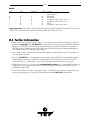
5
3LFNXSWKHSKRQH
LI\RXQHHGWHFKQLFDOVXSSRUW
DQGGLDOWKHQXPEHUV
)RU(XURSH
)RUWKH86$
RUVHQGXVD)$;
)RU(XURSH
)RUWKH86$
RUVHQGXVDQ(0DLO
)RU(XURSHVXSSRUW#YRUWH[GH
)RUWKH86$VXSSRUW#LFSYRUWH[FRP
RUFDOORXU%%61
K
RUFKHFNRXU:HEVLWH
KWWSZZZLFSYRUWH[FRP
6
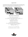
Important Note
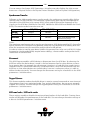
Using modern RAID Systems significantly increases data security and availability. Under no
circumstances does it relieve you from a careful and daily backup on tape or a similar backup
media. This is the only method to protect your valuable data against total loss (e.g.,
through fire or theft), accidental deletion, or any other destroying impacts.
Many Thanks to all my Friends
Monika & Wolfgang (the grandmasters)
AnnDee, Lois, Frank, Ken and Andreas (the Phoenix Crew)
Achim, Dieter, Günter, Hooshiar, Norbert, Otto, Ralph, Sam, Steffen, Winfried
(they are the real wizards)
Alfred (AB, "We need .... . I say we have it")
Andreas (AK, or "Kopf nur mit ö")
Michael (Mipf, "where is my CPU ?")
Jürgen (Jogo, "Hi, is Jurgen there ?")
Ruth (RA, "she had to proof-read that thing, ...)
Johannes (JS, "I want my ice with a red cap .., or Dr. Oops-Click-Click...")
Jürgen (JB, "diesbezüglich & hinsichtlich or probably")
Klaus (KLM, "..not an Airline..")
Markus (Malu, "Luuuuu...."), Uwe
All the fantastic "rest" of this incredible company.
It is not only a pleasure to work here, it is a passion.
7
)&&&
&&&R
RPSOLOLD
DQFH6WDWHPHQW
,QIRUPDWLRQIRUWKH8VHU
127(7KLVHTXLSPHQWKDVEHHQWHVWHGDQGIRXQGWRFRPSO\ZLWKWKHOLPLWVIRUD&ODVV%
GLJLWDOGHYLFHSXUVXDQWWR3DUWRIWKH)&&5XOHV7KHVHOLPLWVDUHGHVLJQHGWRSURYLGH
UHDVRQDEOHSURWHFWLRQDJDLQVWKDUPIXOLQWHUIHUHQFHLQUHVLGHQWLDOLQVWDOODWLRQV7KLVHTXLS
PHQWJHQHUDWHVXVHVDQGFDQUDGLDWHUDGLRIUHTXHQF\HQHUJ\DQGLIQRWLQVWDOOHGDQGXVHG
LQDFFRUGDQFHZLWKWKHLQVWUXFWLRQVPD\FDXVHKDUPIXOLQWHUIHUHQFHWRUDGLRFRPPXQLFD
WLRQV+RZHYHUWKHUHLVQRJXDUDQWHHWKDWLQWHUIHUHQFHZLOOQRWRFFXULQDSDUWLFXODULQVWDO
ODWLRQ,IWKLVHTXLSPHQWGRHVFDXVHKDUPIXOLQWHUIHUHQFHWRUDGLRRUWHOHYLVLRQUHFHSWLRQ
ZKLFKFDQEHGHWHUPLQHGE\WXUQLQJWKHHTXLSPHQWRIIDQGRQWKHXVHULVHQFRXUDJHGWRWU\
WRFRUUHFWWKHLQWHUIHUHQFHE\RQHRUPRUHRIWKHIROORZLQJPHDVXUHV
5HRULHQWDWHRUUHORFDWHWKHUHFHLYLQJDQWHQQD
,QFUHDVHWKHVHSDUDWLRQEHWZHHQWKHHTXLSPHQWDQGWKHUHFHLYHU
3OXJWKHHTXLSPHQWLQWRDQRXWOHWRQDFLUFXLWGLIIHUHQWIURPWKDWWRZKLFKWKHUHFHLYHULV
SRZHUHG
,IQHFHVVDU\FRQVXOWWKHGHDOHURUDQH[SHULHQFHGUDGLR79WHFKQLFLDQIRUDGGLWLRQDO
VXJJHVWLRQV
7KHXVHRIDQRQVKLHOGHGLQWHUIDFHFDEOHZLWKWKHUHIHUHQFHGGHYLFHLVSURKLELWHG
&KDQJHVRUPRGLILFDWLRQVQRWH[SUHVVO\DSSURYHGE\,&3YRUWH[&RPSXWHUV\VWHPH*PE+
FRXOGYRLGWKHDXWKRULW\WRRSHUDWHWKHHTXLSPHQW
8
7DEOHRI&RQWHQWV
$,1752'8&7,21 $3URGXFW,GHQWLILFDWLRQ $.H\)HDWXUHVRIWKH,&3&RQWUROOHUVRIWKH*'7516HULHV $&RS\ULJKWV3DWHQWV $6RIWZDUH/LFHQVH$JUHHPHQW $*HQHUDO,QIRUPDWLRQ $8QSDFNLQJWKH,&3&RQWUROOHU $'HOLYHU\&RQWHQWV $&RQWHQWVRIWKH,&3&'520 $%HIRUH<RX6WDUW $3URGXFW'HVFULSWLRQ $,QWHOL51,23URFHVVRU $%LW$UFKLWHFWXUH $&DFKH5$0([SDQGDEOHWR0% $&RPSDWLELOLW\3&, $8SWR)LEUH&KDQQHO,QWHUIDFHVSOXV8OWUD:LGH6&6,&KDQQHO $,&3&RQWUROOHU)LUPZDUH5$,'<1(3&,%,26DQG*'76(783 $&RQILJXUDWLRQ3URJUDP*'76(783 $'LDJQRVLV3URJUDPV,&35$,'1DYLJDWRUDQG*'7021 $2SHUDWLQJ6\VWHP'ULYHU6RIWZDUH $,&3&RQWUROOHU*'7516HULHV%RDUG/D\RXW %+$5':$5(,167$//$7,21 %%HIRUH,QVWDOODWLRQ %7RROV %,QVWDOOLQJWKH,&3(&&6'5$00RGXOH(60 %)LEUH&KDQQHO$UELWUDWHG/RRS7RSRORJ\)DFWV %)LEUH&KDQQHO+DUG'ULYHV %)&+DUG'ULYH(QFORVXUHV %)&&RQQHFWRUVDQG&DEOHV %0HGLD,QWHUIDFH$GDSWHU0,$,&32UGHU1R %7KH%DVLFVRI6&6, %6&6,&DEOHV %6&6,7HUPLQDWLRQ %6&6,,' 9
%,&36&6,$FFHVVRULHV %([DPSOHV 7ZR,QWHUQDO6&6,'HYLFHV%LWDQG%LW %,&3&RQWUROOHU,QVWDOODWLRQ %,&3&RQWUROOHU)XQFWLRQ&KHFN %3&,[&RPSDWLELOLW\5HTXLUHPHQWV %6ZLWFKLQJ2QWKH3&,&RPSXWHU6\VWHP %7URXEOH6KRRWLQJ %&KHFNLQJWKH,&3&RQWUROOHU&RQILJXUDWLRQ %/RDGLQJ*'76(783 %8SGDWLQJWKH,&3&RQWUROOHU:LWK1HZ)LUPZDUHDQG%,269HUVLRQV %$GGLWLRQDO1RWHV &48,&.6(783 &:KDWLVWKH$LPRI4XLFN6HWXS" &:KDWLVWKH,&3&RQWUROOHU)LUPZDUH" &7KH'LIIHUHQW5$,'/HYHOV &+RZDUHWKH,&3)LUPZDUH)HDWXUHV$FWLYDWHG" &7KH([SUHVV6HWXS)XQFWLRQRI*'76(783 &/HYHOVRI+LHUDUFK\:LWKLQWKH,&3)LUPZDUH &8VLQJ&'520V'$7V7DSHVHWF &([DPSOH,QVWDOOLQJD6LQJOH+DUG'LVN &([DPSOH,QVWDOOLQJD0LUURULQJ$UUD\5$,' &([DPSOH,QVWDOOLQJD5$,''LVN$UUD\ &([DPSOH5$,''LVN$UUD\V:LWKD+RW)L['ULYH &7U\LQJWR$QVZHU7KH,QLWLDO4XHVWLRQV &+RZ0DQ\+DUG'LVNV6KRXOGEH,QWHJUDWHG,QWRWKH'LVN$UUD\" &:KLFK/HYHORI5HGXQGDQF\LV1HHGHG" &'RZH1HHG+RW)L[GULYHV" &6WDWHVRID5$,'<1('LVN$UUD\ &,GOH6WDWH &%XLOG6WDWH &5HDG\6WDWH &)DLO6WDWH &5HEXLOG6WDWH &([SDQG6WDWH &(UURU6WDWH '86,1*0,&5262)706'26 10
'7UDQVSDUHQF\RI+RVW'ULYHV '3DUWLWLRQLQJD+RVW'ULYHDQG7UDQVIHUULQJ06'26 '&21),*6<6DQGWKH'ULYHU*'7;(;( '([SDQGHG0HPRU\0DQDJHUV '8VLQJ:LQGRZV[ '8VLQJD&'520'ULYHXQGHU06'26RU:LQGRZV[ '([DPSOH8VLQJWKH$6:6RIWZDUHIRUWKH&'520 '([DPSOH8VLQJFRUHO6&6,IRUWKH&'520 '7KH,&3$63,0DQDJHU*'7$63,(;( '8VLQJ$6:$63,',6.6<6 '8VLQJFRUHO6&6, ',QVWDOOLQJ:LQGRZV '7KH,&3&RQWUROOHULVWKHSULPDU\FRQWUROOHU '7KH,&3&RQWUROOHULVWKHVHFRQGDU\FRQWUROOHU '8SGDWHWKH,&3:LQGRZV'ULYHU ',QVWDOOLQJ:LQGRZV (86,1*129(//1(7:$5( (7UDQVSDUHQF\RI+RVW'ULYHV (1RYHOO1HW:DUHDQG (1RYHOO1HW:DUH[²8VLQJ'6.'ULYHU (1RYHOO1HW:DUH[²8VLQJ+$0'ULYHU (7LSVDQG7ULFNV (2SWLPL]H'DWD7KURXJKSXW (
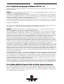
FDFKHPHPRU\DOORFDWRURXWRIDYDLODEOHPHPRU\
LQ3&,,6$6\VWHPV (,QVWDOOLQJ1HW:DUH:URQJ'ULYH1DPH (1HW:DUH6HUYHU1RW6WDEOH:KHQ+LJK8WLOL]DWLRQ (,&3&RQWUROOHUDQG1RQ$63,&RPSDWLEOH&RQWUROOHUV (/DVW6WDWXV,QIRUPDWLRQ ($GGLQJ$GGLWLRQDO&DSDFLW\$IWHU$Q2QOLQH&DSDFLW\([SDQVLRQ (1RWHVRQ$5&VHUYH )86,1*0,&5262)7:,1'2:617 )7UDQVSDUHQF\RI+RVW'ULYHV )*HQHUDO,QIRUPDWLRQRQ:LQGRZV17 )3UHSDULQJWKH,QVWDOODWLRQ )7KH,QVWDOODWLRQ )7KH,&3&RQWUROOHULVWKHRQO\&RQWUROOHULQWKH6\VWHP 11
)7KH,&3&RQWUROOHULVWKH6HFRQGDU\&RQWUROOHULQWKH6\VWHP )8VLQJWKH+RW3OXJ)XQFWLRQZLWK5$,'+RVW'ULYHV ),QVWDOODWLRQRIDQHZ*'7;6<6'ULYHU9HUVLRQ ),QVWDOODWLRQRID5HPRYDEOH+DUG'LVN )7LSV7ULFNV ),&3&RQWUROOHUQRW)RXQG'XULQJ:LQGRZV17,QVWDOODWLRQ ),QVWDOODWLRQDQG8SJUDGHRI:LQGRZV17[[ )$GGLQJ$GGLWLRQDO&DSDFLW\$IWHU$Q2QOLQH&DSDFLW\([SDQVLRQ ):LQGRZV17(UURU0HVVDJHVDQG3RVVLEOH5HDVRQV *86,1*/,18; *7UDQVSDUHQF\RI+RVW'ULYHV *$YDLODEOH'ULYHUVDQG7RROV *8SGDWLQJWKHGULYHUXVLQJWKHGULYHUVRXUFHV *'ULYHULQVWDOODWLRQRUXSGDWHXVLQJDSDWFK **'70210RQLWRULQJ7RRO *JGWKGULYHUSDUDPHWHUV *1RWHV +86,1*6&281,;9 +7UDQVSDUHQF\RI+RVW'ULYHV +*HQHUDO7LSVIRU,QVWDOODWLRQ +,QVWUXFWLRQVRQPNGHY$'0IRUY[ +,QVWUXFWLRQVRQPNGHY$'0IRUY[2SHQ6HUYHU +)XUWKHU,QIRUPDWLRQ ,86,1*81,;:$5( ,7UDQVSDUHQF\RI+RVW'ULYHV ,*HQHUDO,QVWDOODWLRQ1RWHV ,,&3&RQWUROOHUDV%RRW&RQWUROOHU ,,&3&RQWUROOHUDVDQDGGLWLRQDO&RQWUROOHU ,&RRUGLQDWHVRI6&6,GHYLFHV ,)XUWKHU,QIRUPDWLRQ -7+(',$*126,6352*5$0*'7021 -/RDGLQJ*'7021 -/RDGLQJWKH*'70213URJUDP8QGHU1HW:DUH -/RDGLQJWKH*'70213URJUDP8QGHU26 12
-/RDGLQJWKH*'70213URJUDP8QGHU:LQGRZV17 -/RDGLQJWKH*'70213URJUDP8QGHU:LQGRZV -/RDGLQJJGWPRQXQGHU6&281,; -/RDGLQJJGWPRQXQGHU/,18; -7KH*'70213URJUDP -6HOHFW&RQWUROOHU -+RVW'ULYHV -/RJLFDO'ULYHV -3K\VLFDO'ULYHV -&DFKH6WDWLVWLFV -6DPSOLQJ5DWH -7KH0HQX9LHZ&KDQJH6HWWLQJV -1RWHVDQG,QIRUPDWLRQRQWKH+RW3OXJIXQFWLRQRI*'7021 -&RQWUROOHU -&DFKH6HWWLQJV -3K\VLFDO'ULYHV -/RJLFDO'ULYHV -$UUD\'ULYHV -6DYH,QIRUPDWLRQ .,&35$,'1$9,*$725 .,QWURGXFWLRQ .7KH,&35$,'1DYLJDWRU&RQWUROV .7KH7RROEDU .7KH6WDWXV%DU .:LQGRZ0HQX&RPPDQGV .+HOS0HQX&RPPDQGV .)LOH0HQX&RPPDQGV .9LHZ0HQX&RPPDQGV .7KH&KDUW0HQX .7KH&RQILJXUDWLRQ0HQX&RPPDQGV .6HOHFW&RQWUROOHU .3K\VLFDO&RQILJXUDWLRQ:LQGRZ .&RQWUROOHUV .,23URFHVVRUV .'LUHFW$FFHVV'HYLFHV .1RQGLUHFWDFFHVVGHYLFHVUDZGHYLFHV ./RJLFDO&RQILJXUDWLRQ:LQGRZ .7KH+RVW'ULYH,QIRUPDWLRQ:LQGRZ .7KH$UUD\'ULYH,QIRUPDWLRQ:LQGRZ 13
.7KH/RJLFDO'ULYH,QIRUPDWLRQ:LQGRZ .&KDQJHWKHQDPHRID'ULYH .5HPRYHD+RVW'ULYH .&UHDWHDQHZ+RVW'ULYH .3DULW\9HULI\ .3DULW\5HFDOFXODWH .3URJUHVV,QIRUPDWLRQ .([SDQVLRQRIDQ$UUD\ .$GGD+RW)L['ULYH .5HPRYHD+RW)L['ULYH .+RW)L[3RRO$FFHVV .$GGD5$,'&RPSRQHQW0LUURUD'ULYH .5HPRYHD5$,'&RPSRQHQW5HPRYHD0LUURU'ULYH .5HSODFHD/RJLFDO'ULYH .7KH'LIIHUHQW6WDWHVRIDQ$UUD\'ULYH .7KH6WDWLVWLFV:LQGRZ .7KH&RQWUROOHU(YHQWV:LQGRZ .,&35$,'1DYLJDWRU+HOS .,&36HUYLFHDQG,&30DLO /$33(1',; /7HFKQLFDO'DWDRIWKH,&3&RQWUROOHU /%RRW(UURU0HVVDJHV //('VDQG-XPSHUV /,QGH[ 14
15
&KDSWHU$
*HQHUDO
,QIRUPDWLRQ
16
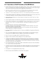
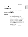
$,QWURGXFWLRQ
%LW+DUGZDUH5$,''LVN$UUD\&RQWUROOHUVZLWKRU)LEUH&KDQQHO,QWHUIDFHVIRU
%LWDQG%LW3&,%XV&RPSXWHU6\VWHPV
In order to take full advantage of modern operating systems, high performance computer
systems are needed. When assessing the performance of a computer system, the aspects
speed and security of the mass-storage subsystem are gaining increasing importance. As a
result of the constantly growing acceptance of the RAID technology (Redundant Array of
Independent Disks) in these computer systems, and the identification of the RAID controller as the essential part of a disk subsystem, a strong demand for suitable RAID controllers
has emerged during the past few years.
Since 1990, ICP vortex has been intensively engaged in the research and development of
RAID products for the highest performance and security requirements. Due to our products’
outstanding performance, our expertise and continuity in development, ICP Controllers are
accepted and known as top leading-edge products all over the world. ICP Controller products within the GDT RN Series are suitable for the most different platforms and applications. All ICP Controllers of the GDT RN Series are pure-bred hardware solutions.
All functionality required for the very complex tasks is hardware-implemented on the controller. Thus, RAID is fully independent of the computer system (the host) and the operating system.
Thanks to the wide operating system support and easy-to-use installation and maintenance
utilities, setting up and using high performance and fault-tolerant mass-storage subsystems for almost every purpose is child’s play.
We would like to thank you for purchasing an ICP Controller of the GDT RN Series.
,&3,QWHOOLJHQW&RPSXWHU3HULSKHUDOV
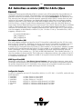
$3URGXFW,GHQWLILFDWLRQ
In order to meet the various customer and system requirements, ICP vortex offers four 64
Bit Fibre Channel RAID Disk Array Controllers for PC-based 32 Bit and 64 Bit PCI computer
systems. The main differences between the controllers lie in the number of Fibre Channel
Interfaces and the Clustering Support .
2UGHU
1XPEHU
,&3
3&
&RQWUROOOOH
HU
1DPH
*'751
*'751
*'751
*'751
1XPEHU
UR
RI
)LEUH
H&
&KDQQHO
,QWHUIDFHV
2 QH
:LGH8OWUD
6&6,
,&
&KDQQHO
<HV
<HV
<HV
<HV
&OXVWHULQJ
6XSS
SSR
RUW
6XSSRUWHG
5$,'
'//HYHOV
2SWLRQDO
2SWLRQDO
<HV
<HV
17
$.H\)HDWXUHVRIWKH,&3&RQWUROOHUVRIWKH*'7516HULHV
64 Bit Hardware RAID Controllers with RAID 0, RAID 1, RAID 4, RAID 5 and RAID 10 Array
Drives at controller level, completely independent of the computer system and the operating system. Several Array Drives can be operated simultaneously.
Operation in 64 Bit and 32 Bit PCI slots. Full Bus Mastering. Maximum data transfer
rates: 132MB/sec in a 32 Bit PCI slot and 264MB/sec in a 64 Bit PCI slot.
"Private" (i.e, for one Array Drive) or "Pool" (i.e., for several Array Drives) Hot Fix Drives.
Online Capacity Expansion. Add one or several new disk drives to an existing Array Drive
to expand its capacity. During the Expansion all data are redundant.
Online RAID Level Migration. Online change of an Array Drive's RAID Level, e.g., from
RAID 0 to RAID 5.
Online Capacity Expansion and RAID Level migration can be performed simultaneously.
ROM-resident configuration utility GDTSETUP. Express Setup option to easily setup Array Drives. Press "CTRL-G" to load GDTSETUP, long before the operating system is
booted.
ICP RAID Navigator. GUI-Tool for Windows 95/98/NT.
GDTMON. Character oriented program for Windows 95/98/NT, NetWare, Linux, OS/2,
SCO UNIX, UnixWare, Interactive UNIX.
Both tools allow the setup and monitoring of ICP Controllers with their array drives.
Remote operation. Intelligent messaging.
On-Board i960RN © Intelligent 64 Bit I/O Processor (100MHz). Completely offloads the
host CPU.
One, or two 64 Bit Fibre Channel Interfaces with HP Tachyon TL and onboard copper
transceivers with 100MB/s channel. Support of Arbitrated Loop Topology.
Up to 25 meters with copper cable. Standard DB9 connectors.
Support of MIAs (Media Interface Adapter) for large cable length.
1 full-featured additional Wide/Ultra SCSI channel for legacy SCSI devices (hard disks,
CDROMs,. etc.) with third generation 32 SCSI RISC processor and an active, softwareswitchable termination. Dual connector system (50 pin and 68 pin connector). Synchronous data transfer rate up to 40MB/sec.
ECC-SDRAM-Module as Cache RAM: 16MB; 32MB, 64MB. Automatic Cache RAM detection. Optional Battery Backup Module.
Intelligent multi-level cache-algorithm with adaptive delayed write and read ahead functions. This ensures an optimized cache for various load profiles and system requirements.
On-Board PCI 2.x compatible BIOS (Plug & Play).
BIOS, Firmware and GDTSETUP in Flash-RAM. Easy update.
18
Drivers for MS-DOS, Novell NetWare, SCO UNIX V/386, Interactive UNIX, UnixWare, Linux, Windows NT, Windows 95/98 and OS/2. ASPI-Managers for DOS, Windows and
Novell NetWare. I20 ready controller design.
Controllers equipped with Cluster RAIDYNE® Firmware (GDT7619RN and GDT7629RN)
include support for Microsoft® Cluster Server® (MSCS).
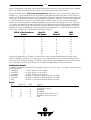
$&RS\ULJKWV3DWHQWV
Parts of the ICP GDT RN Series controllers are protected under international copyright laws
and agreements. No part of the product or the manual, or parts of the manual may be reproduced in any form, physical, electronic, photographic, or otherwise, without the expressed written consent of ICP vortex Computersysteme GmbH. For this product a patent is
registered at the Deutsches Patentamt in Munich with the official reference no. 4121974.
All special names and trademarks of manufacturers quoted in this manual are protected by
copyright.
ICP - Intelligent Computer Peripherals ® and RAIDYNE ®, are registered trademarks of
ICP vortex Computersysteme GmbH.
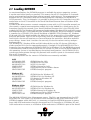
Europe:
ICP vortex Computersysteme GmbH 3 Falterstraße 51-53 3 74223 Flein - Germany 3
Phone: +49-(0)-7131-5972-0 3 Fax: +49-(0)-7131-255063 BBS: +49-(0)-7131-5972-15 (24h;
19200, 8N1) 3 E-Mail: [email protected] 3 WWW: http://www.icp-vortex.com
United States of America:
ICP vortex Corporation 3 4857 West Van Buren Street 3 85043 Phoenix, Arizona 3 Phone:
602-353-0303 3 Fax: 602-353-0051 3 E-Mail: [email protected] 3 WWW:
http://www.icp-vortex.com
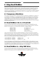
ICP vortex is member of the RAID Advisory Board, the PCI Special Interest Group (PCI SIG)
and founding member of the I2O Special Interest Group (I2O SIG):
19
$6RIWZDUH/LFHQVH$JUHHPHQW
Please read this Software License Agreement before opening the CD/disk packaging and
before starting to use the programs. Each loading of a program covered by this license
agreement, each transmission within any existing network to another computer, as well as
each copy on a mass storage system, regardless of what kind (floppy disk, hard disk, CD,
MO, etc.), represents a duplication of the program according to copyright regulations. Duplication is permitted only with the authorization of ICP vortex.
This authorization will be granted only on the condition that the Software License Agreement stated hereafter is observed.
By opening the CD/disk packaging you expressly acknowledge the Software License
Agreement of ICP vortex.
1. You are authorized to use the software contained on the enclosed disks, CDROMs
and EPROMs/Flash-RAMs on a single computer system only. The restriction to this
one computer system also applies if the disk packaging contains a double set of software, for example one set of 3.5" floppy disks and a CDROM. It is further valid if the
package contains several versions of software adapted to different operating systems.
A multi-utilization of the software is only permitted when a multi-user license has
been purchased. The number of further computer systems authorized for usage under
a multi-user license is evident from and limited by that license.
2. It is permitted to produce one single copy disk of the software for back-up purposes
only. Furthermore, it is permitted to copy the software onto the hard disk of one single computer. It is not permitted to duplicate the contents of the EPROMs and/or
Flash-RAMs on the ICP Controller.
3. The permanent conferring (by sale or donation) of the software is permitted. The new
proprietor must be registered with ICP vortex and must assume all rights and obligations resulting from this Software license agreement. Each and any other kind of
transfer, especially leasing, is not permitted. Copies made by the first user for security
reasons must be destroyed upon transfer.
4. It is not allowed to change the software in its functions or its appearance (especially
trade mark, firm name and copyright reference) or to edit it in any other way. Neither
is it permitted to de-compile or disassemble the software.
5. The enclosed software has been carefully copied on floppy disks and/or CDROM(s).
However, if the floppy disks and/or CDROM(s) should prove to be faulty, ICP vortex
will exchange them within 4 weeks from the date of purchase.
6. ICP vortex makes no warranties, express or implied, including without limitation the
implied warranties of merchantability, functionality and fitness for a particular purpose. In particular, ICP vortex is not liable to you for any consequential, incidental or
indirect damage arising out of the use of this product.
7. This agreement is subject to the laws of the Federal Republic of Germany. Place of
jurisdiction for both parties is the domicile of ICP vortex Computersysteme GmbH.
20
$*HQHUDO,QIRUPDWLRQ
The ICP Controller should be installed by an authorized ICP vortex distributor. Precondition
for the safe installation is an anti-static work place (earthed mat on the table with wrist
bands connected to an earth). ICP vortex does not take any responsibility for damage arising out of improper installation. This manual contains all the information available at the
time it was written. Errors and/or incomplete information are possible. We are grateful for
any ideas or suggestions for improvement. Additional information may be found in the information file "README.TXT" on the enclosed ICP CDROM. Besides up-to-date information, this file also contains a list of all programs on the CDROM.
The contents of the file README.TXT must be read before the ICP Controller is used
for the first time. Output is possible on printer or screen.
This User's Manual explains the installation and the operation of the ICP Controller. For
information on the use of the computer system and its operating system, please refer to
the corresponding system manuals.
$8QSDFNLQJWKH,&3&RQWUROOHU
Open the show box and take out the ICP Controller (leaving it in its anti-static bag), the
CDROM and this manual.
WARNING: Never take the GDT PCB (Printed Circuit Board) out of the anti-static bag
unless this is done at an anti-static work place, and the person handling the ICP Controller is secured with wrist bands against electrostatic charge. If these instructions
are not observed, the CMOS components on the ICP Controller may be damaged or
destroyed.
Store the show box in a safe and dry place.
$'HOLYHU\&RQWHQWV
The following items are delivered with the ICP Controller:
1.
2.
3.
ICP Controller in a sealed anti-static bag.
Sealed CDROM with driver and installation software.
This User's Manual.
$&RQWHQWVRIWKH,&3&'520
A list of the files and programs delivered with the ICP Controller can be found in the file
README.TXT on the enclosed CDROM. The contents of this file can be viewed on screen
or output on your printer. Besides these files and programs there are also disk images of all
ICP driver floppy disks, which can be used with a special image-writing program to create a
full set of disks. This can be helpful if you require for example a BTLD floppy disk for the
installation of the ICP Controller under SCO UNIX.
$%HIRUH<RX6WDUW
In order to avoid damage caused by improper or faulty usage or handling, we strongly recommend reading this manual carefully before installation or first operation.
21
$3URGXFW'HVFULSWLRQ
$,QWHOL51,23URFHVVRU
The i960RN I/O processor is a member of a new RISC CPU generation which was specifically
designed for I/O applications. This pure 64 Bit CPU on an ICP Controller can reach a performance of +100 MIPS and supervises all tasks of the Fibre Channel / SCSI devices, the
RAID controlling and the communication with the PCI computer. In doing so, it significantly offloads the PCI computer, leaving it free to perform its original tasks.
$%LW$UFKLWHFWXUH
To meet the demands on a high performance controller, the bus architecture of the ICP
Controller has a 64 Bit layout.
64 Bit control processor (i960RN I/O Processor)
64 Bit Fibre Channel processors (Tachyon TL)
64 Bit bus-interface (PCI)
$&DFKH5$0([SDQGDEOHWR0%
The cache RAM of an ICP Controller consists of one ICP ECC-SDRAM-Module (ESM). The
cache size is flexible as different memory sizes can be obtained by using different modules.
Thus, the memory can be expanded to 16MB, 32MB or 64MB. An intelligent multi-level
cache algorithm ensures that a high hit rate (cache hit) is achieved. Both, look-ahead and
special delayed-write cache functions are implemented. With the ICP configuration program GDTSETUP and the monitoring utilities GDTMON and ICP RAID Navigator, the user
can adjust various cache parameters.
$&RPSDWLELOLW\3&,
The ICP Controllers have been developed in accordance with the 2.1 PCI-Bus specifications.
They perform full bus-master DMA and can be operated in both, 32 Bit and 64 Bit PCI bus
mastering slots. The transfer rates are 132MB/sec in a 32 Bit PCI slot and 264MB/sec in a 64
Bit slot.
$8SWR)LEUH&KDQQHO,QWHUIDFHVSOXV8OWUD:LGH6&6,&KDQQHO
The ICP Controllers are available with one or two Fibre Channel interfaces and have always
one Wide/Ultra SCSI channel for legacy SCSI devices. Per Loop up to 126 devices can be
connected. The maximum data transfer rate is 100MB/sec on the Fibre Channel and
40MB/sec on the Wide/Ultra SCSI channel.
The Wide/Ultra SCSI channel is equipped with a SCSI-2-compliant (alternative 2), active, and
software-switchable SCSI bus termination, which allows for a separate termination of the
lower and higher byte of the SCSI bus.
$,&3&RQWUROOHU)LUPZDUH5$,'<1( 3&,%,26DQG*'76(783
The firmware, the BIOS of the ICP Controller and the configuration program GDTSETUP are
stored in a Flash-RAM on the ICP Controller PCB. The firmware is designed for parallel
processing and it controls all resources of the ICP Controller. This means that the entire
administration of the devices and RAID is exclusively carried out by the ICP Controller.
Thus, the host is significantly offloaded. In addition, this hardware-implemented solution
guarantees the highest achievable security. The controller-BIOS provides a complete PCI
22
compatible INT13 interface (with 8GB DOS-partition extension and 7 BIOS drives) and expands the respective functions of the system BIOS. It also ensures that operating systems
using the INT13 (i.e. MS-DOS, Windows NT) can be booted directly from a device / RAID
Array Drive connected to the ICP Controller. The RAIDYNE® firmware allows for the simultaneous operation of disk arrays with the RAID Levels 0, 1, 4, 5, 10. RAIDYNE is also capable of performing an online capacity expansion of an existing array by adding one ore more
new hard disks. During expansion the array is fully operational. Another feature of
RAIDYNE® is the online RAID Level Migration of an existing array, e.g., from RAID 0 to
RAID 5.
GDT7619RN and GDT7629RN are equipped with the "Cluster RAIDYNE®" firmware, which
not only includes all necessary functions for supporting the Microsoft® Cluster Server®
(MSCS), but is also ready for future Controller and Server-Cluster concepts. There is an optional "Cluster Module" to upgrade GDT75x9RN to GDT76x9RN.
$&RQILJXUDWLRQ3URJUDP*'76(783
GDTSETUP is either loadable from the Flash-RAM of the ICP Controller (press <CTRL><G>
after the ICP Controller shows its BIOS), or from the command prompt under MS-DOS.
GDTSETUP has a character-oriented graphical user interface. It provides besides others the
following functions:
Configuration of SCSI and Fibre Channel devices connected to the ICP Controller and
administrated by RAIDYNE®. These are normally all types of hard disks. Other devices like CDROM, DAT, DLT, WORM, MOD, etc. are either operated by means of the
ASPI interface, or are directly supported by the operating system (RAW device).
EXPRESS and ADVANCED configuration of single disks, or RAID 0, 1, 4, 5 and 10 array drives.
Configuration of the ICP Controller's cache.
$'LDJQRVLV3URJUDPV,&35$,'1DYLJDWRUDQG*'7021
These two diagnosis programs are very flexible software tools that offer many different diagnosis and maintenance functions during full-operation conditions. GDTMON has a character-oriented user surface and is ideally suitable for NetWare and all types of UNIXes
including Linux. ICP RAID Navigator has a Windows NT compliant graphical user interface
(GUI) and can be operated under Windows 95/98/NT. Booth tools can be used on the fileserver, or remotely from an authorized workstation. The main functions are:
Monitoring the disk subsystem performance (KB/sec and I/Os per sec.)
Monitoring the utilization of the on-board cache
Online configuration of the cache memory
Online changes of device parameters
Online check of the parity information of RAID 4 and RAID 5 Array Drives
Online capacity expansion and RAID level migration of existing Array Drives
Hot Plug and Hot Fix
23
$2SHUDWLQJ6\VWHP'ULYHU6RIWZDUH
Drivers for the following operating systems are available:
2SHUDWLQJ6\VWHP
MS-DOS 3.3 to 6.x
Novell NetWare 3.11, 3.12, 4.x, 5.x
SCO UNIX System V/386 3.2v5.x
Interactive UNIX V/386 3.2v3, 3.2v4
SCO UnixWare 2.x and 7
IBM OS/2 2.x, Warp 3, Warp 4
Windows NT
Windows 95/98
Linux
'ULYHULQFOXGHGZLWKWKH&RQWUROOHU
3DFNDJH
Yes
Yes
Yes
Yes
Yes
Yes
Yes
Yes
Yes
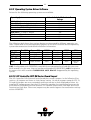
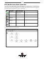
The following table shows how various devices are integrated by different operating systems. Please refer to the corresponding chapters of this User’s manual and the operating
system documentation for detailed installation information.
+DUG'LVN
5HPRY+''
GDT
ASPI or GDT
06'26
GDT
GDT
1HW:DUH
GDT
GDT
81,;/,18;
GDT
Win.NT or GDT
:LQ17
GDT
OS/2 or GDT
26
&'520
ASPI
ASPI
UNIX
Win.NT
ASPI
6WUHDPHU
ASPI
ASPI
UNIX
Win.NT
ASPI
:250
ASPI
ASPI
UNIX
Win.NT
ASPI
02'
ASPI/GDT
ASPI/GDT
UNIX/GDT
Win.NT
ASPI or
GDT
GDT: Configurable with GDTSETUP (some MODs are recognized as a hard disk (see your
MOD manual). In this case, they too can be configured with GDTSETUP). ASPI: Integration
by means of an ASPI interface. UNIX/LINUX, OS/2, Win.NT: Supported by the operating
system.
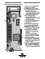
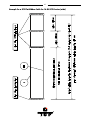
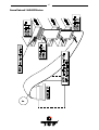
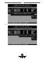
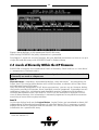
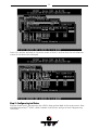
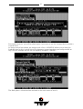
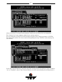
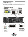
$,&3&RQWUROOHU*'7516HULHV%RDUG/D\RXW
The ICP Controller PCB (Printed Circuit Board) has several jumpers. In the following illustrations, all jumpers are shown in their factory setting. No other jumpers except the TP, TL,
TH and S4 jumpers are user-serviceable and must remain in their displayed position. An
installed TP jumper means that the ICP Controller supplies the termination power on the
SCSI cable of the Wide/Ultra SCSI channel. TL stand for Termination Low-Byte and TH for
Termination High-Byte. These two jumpers may be used to bypass the termination settings
within GDTSETUP.
24
680
6&6,
)&$
*'751DQG*'7512YHUDOO9LHZ
$ODUP
,&
'%307HUPLQDWRU
7HPS
8:6&6,
'%FRQQHFWRUIRU)&$/SRUW$
&38FRROHUIRUL51
6'5$0PRGXOHQRWLQFOXGHG
737HUPLQDWRU3RZHU-XPSHUIRU
:LGH8OWUD6&6,FKDQQHO
7/7+-XPSHUVIRUPDQXDOWHUPL
QDWLRQRI:LGH8OWUD6&6,FKDQQHO
/ /RZ%\WH+ +LJK%\WH
/('V6JUHHQ 6WDWXV
7JUHHQ '0$WUDQVIHU
6&6,)&$\HOORZ $FWLYLW\RQ)&$/
DQG:LGH8OWUD6&6,
&RQQHFWRUVIRUVHFRQGDU\DFRXVWL
FDODQGWHPSHUDWXUHDODUP
/RXGVSHDNHU
&RQQHFWRUIRUSLQ6&6,FDEOH
&RQQHFWRUIRUSLQ6&6,FDEOH
-XPSHU61RUPDOO\FORVHG
%LW3&,%XVFRQQHFWRU&DQDOVR
EHSOXJJHGLQWRD%LW3&,VORW
&RQQHFWRUIRUH[WHUQDO/('V
6XP$OO)&$/DQG:LGH8OWUD
DFWLYLWLHV
)&$$FWLYLW\RQ)&$/SRUW$
6&6,$FWLYLW\RQ:LGH8OWUD6&6,
FKDQQHO&DWKRGHVQHDUWKH
SLQ6&6,FRQQHFWRU
7HUPLQDWRUNH\LI'5$0%DWWHU\
3RZHU0RGXOHQRWLQVWDOOHG.H\
FDQEHDOVRLQVWDOOHGGHJUHHV
FORFNZLVHURWDWHG
6RFNHWIRURSWLRQDO&OXVWHU0RGXOH
1RWUHTXLUHGIRU*'751
:KHQLQVWDOOHGRQD*'751
FRQWUROOHUEHFRPHVD*'751
73
7/
7+
6
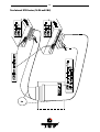
25
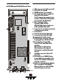
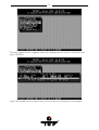
680
6&6,
)&$
)&%
*'751DQG*'7512YHUDOO9LHZ
$ODUP
,&
'%307HUPLQDWRU
7HPS
8:6&6,
'%FRQQHFWRUVIRU)&$/SRUWV$%
&38FRROHUIRUL51
6'5$0PRGXOHQRWLQFOXGHG
737HUPLQDWRU3RZHU-XPSHUIRU
:LGH8OWUD6&6,FKDQQHO
7/7+-XPSHUVIRUPDQXDOWHUPL
QDWLRQRI:LGH8OWUD6&6,FKDQQHO
/ /RZ%\WH+ +LJK%\WH
/('V6JUHHQ 6WDWXV
7JUHHQ '0$WUDQVIHU
6&6,)&$)&%\HOORZ $FWLYLW\RQ
)&$/DQG:LGH8OWUD6&6,
&RQQHFWRUVIRUVHFRQGDU\DFRXVWLFDO
DQGWHPSHUDWXUHDODUP
/RXGVSHDNHU
&RQQHFWRUIRUSLQ6&6,FDEOH
&RQQHFWRUIRUSLQ6&6,FDEOH
-XPSHU61RUPDOO\FORVHG
%LW3&,%XVFRQQHFWRU&DQDOVR
EHSOXJJHGLQWRD%LW3&,VORW
&RQQHFWRUIRUH[WHUQDO/('V
6XP$OO)&$/DQG:LGH8OWUD
DFWLYLWLHV
)&$$FWLYLW\RQ)&$/SRUW$
)&%$FWLYLW\RQ)&$/SRUW%
6&6,$FWLYLW\RQ:LGH8OWUD6&6,
FKDQQHO
&DWKRGHVQHDUWKHSLQ6&6,
FRQQHFWRU
7HUPLQDWRUNH\LI'5$0%DWWHU\
3RZHU0RGXOHQRWLQVWDOOHG.H\
FDQEHDOVRLQVWDOOHGGHJUHHV
FORFNZLVHURWDWHG
6RFNHWIRURSWLRQDO&OXVWHU0RGXOH
1RWUHTXLUHGIRU*'751
:KHQLQVWDOOHGRQD*'751
FRQWUROOHUDSSHDUVEHFRPHV
73
7/
7+
6
26
27
&KDSWHU%
+DUGZDUH
,QVWDOOOOD
DWLRQ
28
%+DUGZDUH,QVWDOODWLRQ
%%HIRUH,QVWDOODWLRQ
The ICP Controller is designed for minimum power consumption and maximum operational security. It therefore contains delicate electrical components (CMOS). In order to
avoid damages caused by electrostatic charges, the following warning must be observed
during installation:
Never take the ICP Controller out of the anti-static bag unless this is done at an antistatic work place and the person handling the ICP Controller is secured against electrostatic charge through wrist bands. If these instructions are not observed, the user
risks damage or destruction of the CMOS components of the ICP Controller !
%7RROV
Before installing, please switch off the complete computer system and remove all cables
including the power cable. Open the case of the host computer with an appropriate screwdriver (usually a medium sized Philips screwdriver).
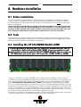
%,QVWDOOLQJWKH,&3(&&6'5$00RGXOH(60
,WLVQRWSRVVLEOHWRRSHUDWHWKH,&3&RQWUROOHUZLWKRXWDQ(607KH,&3
&RQWUROOHULVGHOLYHUHGZLWKRXW(600%3URSHURSHUDWLRQLVRQO\
JUDQWHGZKHQXVLQJDQRULJLQDO,&3(&&6'5$00RGXOH3OHDVHRUGHUDQ
,&3(60ZKHQ\RXRUGHU\RXU,&3&RQWUROOHU0%0%RU0%
If the ICP Controller is not yet equipped with cache RAM, or if another ESM is to be installed, we recommend adding it before you install the ICP Controller in your computer system. As mentioned before, the ICP Controller can be run with three different cache RAM
sizes. The minimum cache RAM size is 16MB. The maximum cache RAM size is 64MB.
The ICP Controller provides one socket for an ICP ECC-SDRAM-Module (SDRAM stands for
Synchronous Dynamic RAM technology). The ESM is correctly plugged into the ESM socket
of the ICP Controller if it is engaged correctly into the socket's retaining clamps and if all
contacts of the ESM are equally contacting the corresponding pins of the socket. To release
an installed ESM, carefully press the retaining clamps to the side.
Each time you switch on the computer system, the ICP Controller automatically recognizes
how much cache RAM is available and configures itself accordingly.
29
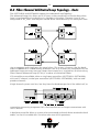
%)LEUH&KDQQHO$UELWUDWHG/RRS7RSRORJ\)DFWV
The GDT75x9RN and GDT76x9RN support the Arbitrated Loop Topology.
The Arbitrated Loop (AL) allows up to 127 ports to be connected in a circular daisy chain.
Data is transferred from one device to its neighbor in the chain. The ports in an AL are
designated as NL_Ports, and two ports can be active simultaneously. The other ports func-
tion as repeaters and simply pass the signal along. This means, of course, that the bandwidth of 100MB/sec is shared among all devices. Just as in a token ring, each device on the
Arbitrated Loop sees every message, keeps those meant for it, and passes all others along.
Fibre Channel Arbitrated Loop (FC-AL) is a subset of a Switched Fabric.
ICP controllers are available either as single port controllers (GDT7519RN, GDT7619RN),
with one FC channel, or dual port controllers (GDT7529RN, GDT7629RN), with two independent channels.
Single channel systems cost less, but they have the disadvantage that if the cable itself, or
some other connecting component fails, the controller can no longer communicate with
the FC devices.
A dual port controller allows a system to be constructed with each device attached to both
cables, so that if one cable fails, the other takes over all IO operations.
30
%)LEUH&KDQQHO+DUG'ULYHV
FC hard drives are built with a 40 pin SCA connector (Single Connector Attachment), which
provides all necessary signal connections and electricity to the hard drives. This SCA connector enables hard drives to be easily built into an external enclosure with an SCA backplane. The drawback of the SCA connector, however, is that the hard drive can no longer be
connected directly to the controller with a simple cable, but needs a specific FC-SCA to DB
9 adapter. This adapter converts the SCA connection on the hard drive into one or, in the
case of a dual port hard drive, into two DB 9 female connectors, so the appropriate DB 9
male connector can be attached. The adapter also has a connector for the electrical current
to the hard disk. When using such adapters, a loop back connector must be used to complete the communication loop.
If the hard drives are used in a dual loop configuration, they must have two NL_Ports.
31
When choosing FC hard drives, those with the shortest seek times and highest RPMs usually provide best performance. The seek time refers to the amount of time the drive
read/write head needs to access specific data sectors on the disk. The shorter the seek
time, the less time spent waiting during random reads/writes. Higher RPMs translate into
better sequential data transfer rates and better read/write times.
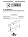
%)&+DUG'ULYH(QFORVXUHV
A FC hard drive enclosure functions not only to physically house the drives, but must also
control electrical current and temperature. In choosing an enclosure, important features to
consider are redundant and hot-swappable power supplies and fans. These components
have a relatively high failure rate and, if they are not redundant, their failure can lead to
hard drive failures. The FC hard drive enclosure assigns to each hard drive a unique ID
in the Loop.
Enclosures for RAID systems must also support the interactive change-out of a hard disk
during system operation (Hot-Plug). To achieve this, the enclosure must have Port Bypass
Circuits (PBC), which are located on the backplane and redirect data paths while the failed
hard drive is exchanged. This prevents disruption of the Arbitrated Loop. While using a system with PBCs, one must take care that the allowable cable lengths between devices specified for FC-AL are not exceeded. In addition, pay attention to whether the enclosure can
support a dual loop configuration. In order to provide the highest level of fault tolerance,
some FC enclosures have two completely independent, redundant loops. If the hard drives
and controller also provide two FC ports, the system can be completely redundant, with
redundant cabling. If one loop fails completely, the second can still carry all communications between controller and hard drives.
Another consideration is whether the enclosure supports Media Interface Adapters (MIA).
32
These adapters transform the electrical signals from hard drives into optical signals. In order for these adapters to function, however, the DB 9 connectors must provide the necessary electrical support. MIAs allow a controller with copper cabling to be used with a fiber
optic system.
A modern enclosure should also provide a management interface, through which a RAID
controller can communicate information regarding the status of the system. For example,
the enclosure would communicate information about fan or power supply failure to the
controller, which would then notify the system administrator. Similarly, the controller
communicates with the enclosure, indicating which hard disk has failed, so that the system
administrator can see on the enclosure display (Fault LEDs or LCDs) which disk needs to
be swapped.
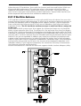
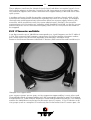
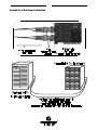
%)&&RQQHFWRUVDQG&DEOHV
A net data transfer rate of 100 MB/sec corresponds to a signal frequency on the FC cable of
1 GHz. This extremely high frequency necessitates the highest quality connectors and cables, which means only those from reputable manufacturers should be used.
Because the distances between individual FC devices (RAID controllers and hard drives) in
Example for a copper cable.
mass storage systems are not great, the less expensive copper cabling is most often used.
Three different kinds of copper cabling with DB 9 connectors (similar to serial PC interface)
are defined for FC: Video Coaxial, Miniature Coaxial and Shielded Twisted Pair. This cabling
enables the 100 MB/sec transfer rate for distances up to 25 meters. If the FC devices or device groups (such as a complete FC enclosure) have to be further than 25 meters apart, the
33
signal transmission can be carried via optical fiber. The 50 µm multi mode optical fibers
with shortwave lasers can handle cable lengths up to 500 meters, and the 62.5 µm multi
Mode optical fibers up to 175 meters. SC duplex connectors should be used in these situations. 9 µm single mode optical fiber with longwave lasers can travel up to 10 km. (The distances discussed here refer to the distance between devices, not the length of the entire
cable, as is the case with SCSI.)
Because the laser power necessary for the extremely long distances poses a threat to the
human eye, a protective system called Open Fiber Control (OFC) has been defined. The receiver normally sends continual acknowledgments of receipt of the laser signals. If the
transmitter does not receive this acknowledgement, the laser signals are immediately
stopped.
There is also a non-OFC system, used when the power of the laser is not dangerous to the
eye, so no receipt acknowledgements are sent. OFC and non-OFC systems are not compatible.
Example for a fibre optics cable.
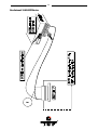
%0HGLD,QWHUIDFH$GDSWHU0,$,&32UGHU1R
MIA adapters transform the electrical signals used by copper cables into optical signals
transmitted by optical fibers. One end of the adapter has an FC DB 9 male connector and
the other end has an SC duplex female connector for the optical fiber.
34
The adapter uses a laser diode to transform electrical signals into light signals and an optical sensor to perform the reverse function. The necessary electricity for the adapter must
be delivered by the DB 9 connector. Compatibility with MIAs is an important point to consider when choosing FC devices. These adapters provide a very cost-effective method to
connect FC devices which are located far from one another.
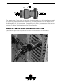
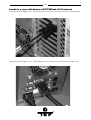
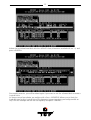
([DPSOHIRUD0,$DQGD6&ILEHURSWLFVFDEOHZLWKD*'751
(MIA and fiber optics cable plugged into the female DB9 connector of the GDT7519RN)
35
(MIA and fiber optics cable plugged into the female DB9 connector of the subsystem)
36
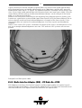
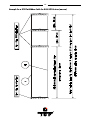
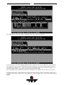
([DPSOHIRUDFRSSHUFDEOHEHWZHHQD*'751DQGD)&$/VXEV\VWHP
(DB9 connector of copper FC-AL cable plugged into the female DB9 connector of the GDT7519RN)
(DB9 connector of copper FC-AL cable plugged into the female DB9 connector of the subsystem)
37
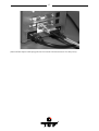
([DPSOHIRUD'XDO/RRS&RQILJXUDWLRQ
38
%7KH%DVLFVRI6&6,
It is very important for you to observe the information and notes given in this section of the
User’s Manual because it helps to ensure that the SCSI devices that are used in connection
with the ICP Controllers are operated in a successful, long-lasting and trouble-free manner.
In many cases, these information are not only applicable to ICP Controllers, but in general
to all those SCSI systems which, like the ICP Controllers, use Single Ended SCSI bus channels. According to its definition, the SCSI bus provides access to several participants that
are physically connected through an appropriate SCSI bus cable. To achieve a sufficiently
good signal quality, it is not only recommended to use very good cables and connectors,
but also to terminate both ends of the cable properly. For an unambiguous identification
on the bus, all participants have a unique number – the so-called SCSI-ID. Further details
on these topics can be found on the following pages.
Please note that 98% of all SCSI-related problems are caused by bad SCSI cables,
wrong SCSI bus termination and duplicate SCSI-IDs.
%6&6,&DEOHV
The quality and overall length of the cable, as well as the number and quality of the SCSI
connectors is very important for both internal and external SCSI cables. Generally, internal
SCSI cables are 50 or 68 conductor flat ribbon cables. To connect external SCSI devices,
round and shielded cables with appropriate connectors are typically used. The minimum
cross section per line has been defined in the SCSI-3 specification as follows:
50 conductor cables: minimum 28 AWG conductors
68 conductor cables: minimum 30 AWG conductors.
and with
The typical impedance of a SCSI cable is 84 Ohm +/- 12 Ohms. The maximum difference in
impedance between two conductors of a SCSI cable must not exceed 12 Ohms. External
round cables should have a SCSI-compliant placement of the inside conductors. Besides
the cables, the right connectors for a cable are also very important. It is highly recommend
to use highest quality connectors, only. The following table shows the maximum cable
lengths allowed for a given transfer rate. Based on many years of SCSI experience, the
lengths we recommend are in some cases shorter than theoretically possible. The information in the table refers to one SCSI channel and represent the overall length of the cable,
including internal and external parts.
SCSI Bus Width
SCSI Mode
8 Bit, narrow
8 Bit, narrow
16 Bit, narrow
16 Bit, wide
16 Bit, wide
Fast
Fast-20, Ultra
Fast
Fast
Fast-20, Ultra
Synchronous Data
transfer Rate
10 MB/sec.
20 MB/sec.
10 MB/sec.
20 MB/sec.
40 MB/sec.
Number of
Participants
8
4
8
8
4
Maximum
Length
2.0 m
1.5 m
2.0 m
2.0 m
1.5 m
With regard to Fast-20 devices, the maximum number of participants and the maximum
cable length have to be strictly observed when a Fast-20 device (even if it is only one) is
running in Fast-20 mode. In each case , the minimum cable length is 0.5 m. In addition to
specifications mentioned above, the following should be kept in mind when selecting and
installing SCSI cables:
39
Always install SCSI cables that are as short as possible. The lengths in the table above
are absolute maximum lengths. (Total length of internal and external cables per channel).
Avoid using SCSI cables with more connectors than actually needed. Never select a SCSI
mode or operate a SCSI device with a cable that is not appropriate for this mode.
The minimum distance between two connectors of a SCSI cable is 20 cm.
Avoid cable stubs. If this is not possible, keep the stub length below 10 cm.
"Star cablings" are not allowed.
Keep the number of transitions from flat to round cables and vice versa as small as possible. It is usually best is to use flat or round cables, only.
Check these points when routing SCSI cables:
- Avoid kinks in the SCSI cable
- Do not roll the SCSI cable up on itself
- Avoid routing the cable next to other cables
- Avoid routing the cable in the vicinity of noise sources such as power supplies
- Avoid routing the cable over sharp edges and in areas where it could get caught up
- Avoid routing/sticking the cable directly onto metal surfaces
Following is a list of some manufacturers of high quality SCSI connectors and cables: 3M,
AMP, Amphenol, Fujitsu, Harting, Honda, Methode, Molex, Robinson Nugent, Yamaichi.
When making home-made SCSI cables, make sure that the insulation displacement connectors are properly aligned and firmly pressed into the flat ribbon cable. Otherwise, the
whole cable might turn out to be a big short-circuit. Furthermore, check carefully that PIN 1
of the cable connects to PIN 1 of the connectors. A simple short-circuit and continuity test
before running the devices helps you to save time and money.
The same warnings as for home-made cables apply when you buy non-brand cables. If you
plan to run Fast-20 devices, you should explicitly ask your dealer if these cables are appropriate for the Fast-20 mode. (Note: The ICP product range also includes some high quality
SCSI accessories. Along with external SCSI brackets, there is a special FAST-20 Wide SCSI
cable. Please see section B.5.4 of this User's Manual or check our Website: http://www.icpvortex.com, for further details).
40
([DPSOHIRUD6&6,)ODW5LEERQ&DEOHIRU%LW6&6,'HYLFHVQDUURZ
41
([DPSOHIRUD6&6,)ODW5LEERQ&DEOHIRU%LW6&6,'HYLFHVZLGH
42
%6&6,7HUPLQDWLRQ
In order to ensure a flawless and interference-free signal transmission on the SCSI bus and
to minimize the detrimental effects of external noise generators, both ends of the SCSI cable have to be terminated. The SCSI specification prescribes two alternative termination
modes for Single-Ended SCSI bus systems: the passive termination and the active termination, also known as Alternative-2 termination. The passive termination consists of a 220
Ohm pull-up and a 330 Ohm pull-down resistor for each signal. Today, the passive termination is mostly used in systems with synchronous data transfer rates not exceeding 5
MB/sec, which is rather slow. The active termination circuit consists of a 110 Ohm precision-resistor per signal and a common 2.85Volt voltage regulator. Thus, all signals are actively pulled up to a certain level. The active termination provides much better signal
quality and significantly reduced liability to noise. All ICP Controllers are equipped with an
active SCSI bus termination. The voltage for the termination circuitry (passive and active) is
supplied either by the SCSI device itself, or by the TERMPWR line of the SCSI bus. Every
SCSI device, regardless of whether it is a hard disk, a printer, or an ICP Controller, must
have a SCSI bus termination. In addition, it must be possible to enable and disable the
SCSI bus termination (on some devices, resistor array packs or a jumper have to be removed, on others, like the ICP Controllers, soft-switches allow a very comfortable setting of
the SCSI bus termination). Furthermore, on each SCSI device it must be possible (for example through a jumper) to switch the voltage on the terminator power line (TERMPWR) of
the SCSI cable on or off. For all configurations with ICP Controllers, we recommend that
you use exclusively SCSI devices with an active SCSI bus termination:
Always use active SCSI bus termination.
Do not use SCSI devices with passive SCSI bus termination (e.g., CDROMs) for the termination of the SCSI cable.
Always terminate only the two ends of a SCSI cable.
The TERMPWR jumper (TP) on the ICP Controller PCB should always be set. In this way, it
is the ICP Controller which supplies the termination power on the SCSI cable and no other
SCSI device may supply termination power on the cable.
The connections listed in the table below are the only valid connections allowed. Any other
connection setup, even if physically possible, is not allowed as it will cause serious malfunctions or even the destruction of the SCSI device and/or the ICP Controller. The termination settings can be changed within GDTSETUP.
Internal female connector,
68 pin
Internal male connector
50 pin
Termination Setting
of the ICP Controller
Occupied and end terminated
Not occupied
Not occupied
Occupied and end terminated
Not occupied
Not occupied
Not occupied
Occupied and end terminated
Occupied and end terminated
Occupied and both ends terminated,
i.e., the connector is located between
the both ends
Not occupied
On
On
On
Off
Off
Occupied and both ends terminated, i.e., the connector is located
between both ends
Off
43
%6&6,,'
All participants on the SCSI bus must have a unique identification number, that is, each
number can only be used once on a given cable. Each SCSI device is uniquely addressed
through its SCSI ID.
All participants of a SCSI bus must have a different SCSI ID.
The factory set SCSI ID of the ICP Controller SCSI channel is 7.
Up to 15 SCSI devices can be connected to a single SCSI bus. SCSI IDs are 0 to 15 (7 is
the default for the ICP Controller).
On hard disks, CDROMs, tape streamers, etc., the SCSI ID is normally set through jumpers
or small DIP switches. The ICP Controllers offer a far more comfortable method: software
switches in the GDTSETUP program allow you to easily set the SCSI ID of an ICP SCSI
channel. It is recommended to leave the default ID value at 7. Some operating systems require that the SCSI ID of certain SCSI device (e.g., tape streamer, CDROM) is set to a particular value (for more information, please refer to the appropriate chapter in this manual).
%,&36&6,$FFHVVRULHV
Order # Part Name
8840
Fast-SCSI
Bracket
8841
Wide-SCSI
Adapter
8842
Wide-SCSI
Bracket
8843
Wide/Ultra
Flat Ribbon
Cable
Narrow-Wide
Bracket
8846
Description
External SCSI connector with an
internal 50 pin header and an external 50 pin HD SCSI connector (female)
16 Bit to 8 Bit SCSI adapter with a 50
pin header and a 68 pin HD SCSI
connector (male)
External SCSI connector with an
internal and an external 68 pin HD
SCSI connector (female)
80 cm Wide/Ultra SCSI cable with
four 68 pin HD SCSI connectors
(male)
External SCSI connector with an
internal 68 pin connector (female)
and an external 50 pin HD SCSI connector (female)
Application
Connection of an external Narrow/Ultra
SCSI subsystem with an internal Narrow/Ultra channel
Connection of Wide/Ultra SCSI devices
with an 8 Bit 50 pin flat ribbon cable
Connection of an external Wide/Ultra
SCSI subsystem with an internal
Wide/Ultra channel
Connection of up to 3 internal Wide/Ultra
SCSI devices per SCSI channel
Connection of an external Narrow/Ultra
SCSI subsystem with an internal
Wide/Ultra channel
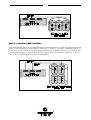
%([DPSOHV
Following are some examples of correct SCSI cablings, SCSI terminations and SCSI-ID settings.
44
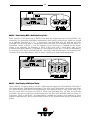
2QH,QWHUQDO%LW6&6,'HYLFH
45
6HYHUDO,QWHUQDO%LW6&6,'HYLFHV
46
7ZR,QWHUQDO6&6,'HYLFHV%LWDQG%LW
47
%,&3&RQWUROOHU,QVWDOODWLRQ
Make sure that the ICP Controller is equipped with an appropriate DIMM (at least 8MB). As
already mentioned in section B.3 of this User's Manual it is not possible to operate the ICP
Controller without an ICP ECC-SDRAM-Module.
Step 1
Switch off the PCI computer system and remove all cables (first of all the power supply).
Step 2
Following the instructions in the computer manual, open the case of the PCI computer, so
that you have easy access to the PCI expansion slots.
Step 3
Select a free 64 Bit PCI bus-master slot and remove the metal bracket, following the instructions in your PCI computer manual. It is essential that the ICP Controller is plugged
into a bus-master slot (it will NOT work in a slave or non-bus-master slot). Some motherboards have only 1 bus-master slot. Make sure that the selected slot has a sufficiently
cooling airflow. Permanent overheating of electronic devices decreases their life time drastically. The ICP Controller can be also operated in a 32 Bit PCI bus-master slot. Make
sure that the unused card-edge connector of the ICP Controller has no contact with other
components in the PCI slot area. There are no further settings required to operate the ICP
Controller in a 32 Bit or 64 Bit PCI bus-master slot.
Step 4
Push the ICP Controller firmly into the correct PCI bus-master slot. Make sure that the controller fits tightly into it, and that the external connectors stick out of the computer case.
Now, fix the ICP Controller by tightening the screw of its bracket.
Step 5
To connect the Fibre Channel enclosure use either a copper round cable, or an optical fiber
cable (with MIAs). Make sure that cables are fastened with the corresponding connectors.
To connect internal SCSI devices, use the internal SCSI connectors of the ICP Controller.
You need 50-pin or 68-pin SCSI flat ribbon cables with appropriate connectors. Please verify that the colored core of the SCSI flat ribbon cable connects PIN1 of the ICP SCSI connector to PIN1 of the SCSI device.
Step 6
If required, you can connect the HDD-front-LEDs of the PCI computer system to the LED
connectors of the ICP Controller.
Step 7
Before the PCI computer system is switched on, check the following points over again:
Have you installed an genuine ICP ECC-SDRAM-Module ?
Is the ECC-SDRAM-Module into the socket ?
Is the ICP Controller plugged firmly into one of the PCI bus-master slots ?
Is the Fibre Channel enclosure properly connected with the ICP Controller.
Are the SCSI-IDs set correctly ? Are the SCSI-bus terminators plugged/set correctly ?
Are the SCSI flat ribbon cables connected correctly ?
48
Step 8
After having checked all the points in "Step 7", reconnect the PCI computer system to the
power supply. Do not close the computer case yet.
%,&3&RQWUROOHU)XQFWLRQ&KHFN
Before we put the ICP Controller into operation for the first time, we would like to spend a
few words on the PCI 2.x compatibility requirements a PCI computer system (especially the
motherboard and the motherboard's BIOS) should meet.
%3&,[&RPSDWLELOLW\5HTXLUHPHQWV
A pre-condition for a flawless installation of PCI bus-master expansion cards (the ICP Controllers belong to this group of expansion cards) in a PCI motherboard is a 100% PCI 2.x
compatible System-BIOS.
We have observed more than once that a motherboard declared fully PCI 2.x compatible
was equipped with a System-BIOS (located in an EPROM or FLASH-RAM) which was not
PCI 2.x compatible at all. To make up for this, many manufacturers of PCI motherboards or
PCI computer systems offer their customers a special area on their website from where the
latest PCI-system-BIOS version can be downloaded.
The System is fully PCI compatible.
If your PCI motherboard/computer is 100% PCI compatible, its PCI system-BIOS will, to a
large extent automatically (plug & play), carry out the configuration (e.g., mapping of the ICP
Controller's BIOS and DPMEM, assignment of a proper system IRQ to a PCI interrupt). This
means that the PCI computer system (with its motherboard and PCI system-BIOS) must
meet the following requirements:
1. The PCI computer system must automatically assign (map) the ICP Controller BIOS to
an adequate address in the lower, 1MB area of the computer system’s main memory.
2. The PCI computer system must map the ICP Controller’s Dual Ported Memory
(needed for high performance operation) to an adequate address in the lower, 1MB
area of the computer system’s main memory. In addition, it has to disable the shadowing of this address space.
3. Assigning a system IRQ to a PCI interrupt.
The PCI 2.x specification prescribes 4 PCI interrupts, called INT A, INT B, INT C and
INT D. A PCI interrupt must be assigned to a free (unused) IRQ of the PCI motherboard or computer. The ICP Controller is shipped with PCI INT A.
Depending on the manufacturer of the PCI computer system, there two ways to carry
out this task:
automatically (automatic IRQ routing)
with the PCI System-BIOS setup program
Depending on the BIOS manufacturer (e.g., Award, Phoenix, AMI etc.), the setup program is activated by pressing a certain key-combination shortly after the reset (cold
boot or warm boot). For detailed information on the key-combination and the jumpers’ locations and settings, please refer to the system manual of your PCI motherboard or computer.
49
The System is not fully PCI compatible.
Problems may occur if the motherboard and/or System-BIOS are not fully PCI 2.x compatible. The best remedy is to update the PCI system-BIOS to the latest version.
Furthermore, we have integrated into our ICP BIOS various routines (tricks) which remedy
the incompatibilities of some PCI system-BIOSes, at least with regard to the ICP Controller.
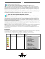
%6ZLWFKLQJ2QWKH3&,&RPSXWHU6\VWHP
Now, after having installed the ICP Controller and the devices, check whether the controller
is working correctly. If the ICP Controller is the only controller in the computer system, set
hard disks C: and D: to not available in the System-BIOS setup program of the computer.
Make sure that the boot priority starts with A, then C, etc..
Normally, you can start the BIOS setup program by pressing a certain key-combination after switching on the computer. After switching on the PCI computer system, pay attention
to the LEDs of the ICP Controller.
If everything is installed correctly, the green LED "S" will light up when
switching on the PCI computer system. The green LED "S" (S for status) shows
that the ICP Controller is online. If this green LED does not react as described
above, switch off the PCI computer and double-check the correct installation
of the ICP Controller.
The electronic loudspeaker of the ICP Controller gives forth a series of 4 signals with a pause between the first two).
The other green LED "T" may flicker sometimes (it always lights up during
BUS-Master DMA transfers; the brighter it lights, the more DMAs).
The yellow LEDs indicate accesses to the devices. They also may flicker occasionally as the ICP Controller scans the I/O channels for existing devices.
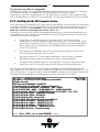
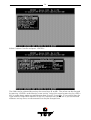
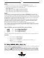
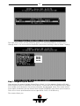
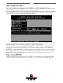
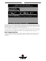
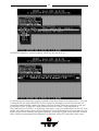
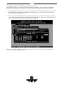
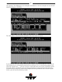
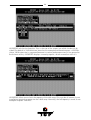
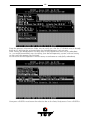
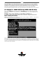
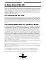
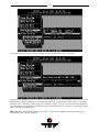
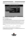
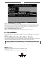
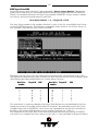
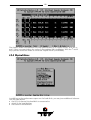
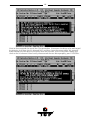
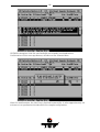
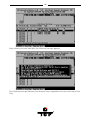
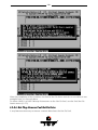
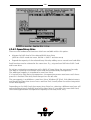
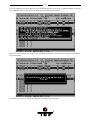
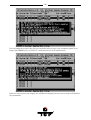
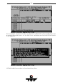
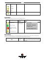
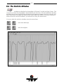
The ICP boot message appears. In the following example, a GDT7519RN Controller has
been detected in PCI slot 3, and it has 32MB of ECC-SDRAM ("16 MB RAM detected..".). On
the SCSI channel is a Quantum drive and a DLT2000XT streamer. On the Fibre Channel port
four Seagate Barracuda drives are detected. They form one RAID-5 host drive.
*'73&,'LVN$UUD\&RQWUROOHU%,269HUVLRQ
&RS\ULJKW&E\,&3YRUWH[&RPSXWHUV\VWHPH*PE+'HF
$OOULJKWVUHVHUYHG
%,26ORFDWHGDW[([()))
&RQWUROOHUVIRXQG6HOIWHVWV2.VFDQQLQJ,2FKDQQHOV
>3&,@'30(0DW['['))),17$ ,54
>3&,@*'751+:/0%6'5$0(&&N%)ODVK5$0
>3&,@6HULDO1R5$,'<1():9HUVLRQ5)))'HF
>3&,@6&6,$,'/8148$1780;3:
>3&,@6&6,$,'/81'/7;7
>3&,@,QLWLDOL]LQJ)LEUH&KDQQHO/LQN
>3&,@)&$/$)LEUH&KDQQHO3ULYDWH/RRSLQLWLDOL]HG
>3&,@)&$/$,'/816($*$7(67)&
>3&,@)&$/$,'/816($*$7(67)&
>3&,@)&$/$,'/816($*$7(67)&
>3&,@)&$/$,'/816($*$7(67)&
>3&,@5$,'+RVW'ULYHLQVWDOOHGUHDG\
3UHVV&75/!*!WRHQWHU*'76(783!!!
50
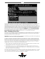
The single messages have the following meaning:
%,26ORFDWHGDW[([()))
Unlike ISA or EISA computers where the BIOS address of a peripheral expansion card is set
manually (ISA, jumpers) or with the help of a configuration file (EISA, cfg file) and the address space is determined by the user, the PCI system-BIOS automatically maps the BIOS
of a PCI compatible peripheral expansion card to a memory address. At each cold or warm
boot, it determines which address space to assign to the BIOS of an expansion card. The
message shown above reports the physical address occupied by the ICP BIOS.
>3&,@
3&, device, bus system , slot. The PCI 2.x specification allows several PCI bus systems to
be present in one PCI computer. All ICP Controllers have been designed to support multiple PCI bus system computers. The slot number indicated in the message above does not
refer to the 3rd PCI slot, but indicates that the ICP Controller is plugged into a slot which is
the third one the PCI chipset of the PCI computer can access. To determine which physical
PCI slot this corresponds to, consult the system manual of your PCI computer.
'30(0DW['['))),17$ ,54
'30(0stands for 'ual 3orted 0(0ory. The ICP Controller needs this 16KB address space of
the PCI Computer for the command communication. In our example, the address space
begins at D000:0000 and ends at D000:3FFF (D000 is the segment address). As with the ICP
Controller BIOS, this mapping, is also automatically carried out by the PCI system-BIOS.
This information is essential when installing Expanded Memory Managers under DOS and
Windows. The ICP DPMEM address space has to be excluded from the control of such a
manager. (For more details, see chapter D of this manual). Furthermore, this messages tells
us that the PCI ,17$ of the ICP Controller has been assigned to the system,54. This assignment, is also carried out automatically if the PCI system-BIOS is 100% PCI 2.X compatible.
*'751+:/0%6'5$0(&&N%)ODVK5$0
*'751+:/ stands for the type of ICP Controller found by the ICP BIOS. HWL means
Hardware level. 0%6'5$0(&&indicates that the installed ECC module has 32MB. Depending on the size of the installed ECC-SDRAM-Module (ESM) the following messages are
possible (xx = 16, 32, 64):
[[0%6'5$0(&&
xx MB ECC-SDRAM-Module
N%indicates the size of the installed Flash-RAM.
6&6,$indicates the SCSI devices connected with the controller's separate Ultra Wide SCSI
channel. )&$/$RU)&$/%ZLWKD*'7[51indicates the Fibre Channel devices connected
with the controller's Fibre Channel Arbitrated Loops.
3UHVV&75/!*!WRHQWHU*'76(783!!!
After pressing this hot-key, the message (QWHULQJ*'76(7833OHDVHZDLWappears. The IO
bus scan is completed and the built-in GDTSETUP configuration program is loaded. It allows you to configure RAID Array Drives.
%7URXEOH6KRRWLQJ
If these messages do not appear on the screen, or if other problems occur after switching
on the computer system (screen remains dark etc.), you should check the entire installation
over again:
51
Are you using a genuine ICP ECC-SDRAM-Module (ESM) ?
Try another one.
ESM plugged firmly into the socket ?
Unplug it and plug it in again.
Is the ICP Controller plugged into a PCI bus-master Slot ?
Check this. If necessary, try another slot.
Is the Fibre Channel cable OK ?
Check length and connectors. Try another cable.
Is the SCSI cable OK ?
Check the length and connectors, Try another cable..
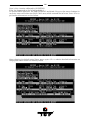
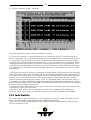
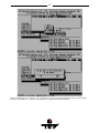
If the PCI System-BIOS is not PCI 2.x compatible (see above), the ICP Controller BIOS
may display one or more of the following messages:
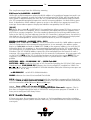
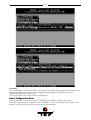
(i) The DPMEM has not been installed correctly.
(UURU
6\VWHP%,26QRW3&,FRPSOLDQWFRQWDFW\RXUPDLQERDUGVXSSOLHU
&RQWUROOHUDW[\KDVLQYDOLG'30(0DGGUHVV
7U\LQJWRDOORFDWHDIUHHDGGUHVV
)RXQGIUHHDGGUHVVDWDFFHSW"<HV1R$ERUW<
&DXWLRQWKLVDGGUHVVPXVWQRWEHXVHGE\DQRWKHUH[SDQVLRQFDUG
In this case, the system-BIOS has not installed the Dual Ported Memory of the ICP Controller correctly. Therefore, the ICP Controller will search for an adequate address. If you
accept the suggested address (<), the ICP Controller will install its DPMEM starting at this
address. Since this 16KB address space which starts at IUHHDGGUHVV must not be shadowed,
you might have to disable the shadowing manually in the system-BIOS setup program. In
addition, make sure that this address space is not used by another expansion card. (This is
a work-around, not a solution. PCI 2.x is a well defined specification, and a fully compatible
system-BIOS should have assigned the DPMEM automatically.)
If the ICP BIOS could not find an appropriate address, the following message is displayed:
&DQQRWVHW'30(0DGGUHVVDERUWLQJ
In this event, you can try to select a new address after resetting the computer. If this fails,
too, there is no other way but to update the PCI system-BIOS.
(ii) The IRQ to PCI INT assignment doesn’t work properly.
:DUQLQJ
FRQWUROOHUDW[\6\VWHP%,26FRQILJXUHG,54=EXWXVHV8
This warning indicates a bug in the PCI System-BIOS, too: It did not succeed in correctly
assigning an IRQ to a PCI INT. The ICP Controller will function, but the ICP BIOS must not
be disabled whatsoever.
(iii) The IRQ to PCI INT assignment doesn’t work at all.
(UURU
FRQWUROOHUDW[\FRXOGQRWUHDG,54VHWWLQJ
If this error message is displayed, the ICP Controller will not work.
52
In all these cases you should - in case (iii) you have to - update your PCI system-BIOS as
soon as possible.
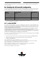
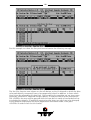
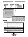
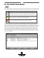
%&KHFNLQJWKH,&3&RQWUROOHU&RQILJXUDWLRQ
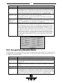
As mentioned before, these settings can be changed through soft-switches in the ICP Controller setup program GDTSETUP. All settings are permanently stored on the ICP Controller. The following table shows the various options and the possible settings.
Function
(*)
Cache On
(*)
Delayed Write On
BIOS
BIOS Warning Level
Supported BIOS Drives
Memory Test
SCSI-ID SCSI-A
SCSI Termination
(*)
(**)
Possible Settings
On, Off
On, Off
(**)
Enabled, Disabled, Removed
All messages, Fatal errors
2,7
No Test, Standard, Double Scan, Intensive
0,1,2,3,4,5,6,7
On, Off, Auto
Factory Setting
On
On
Enabled
Fatal errors
7
Standard
7
Auto
Can also be changed with the GDTMON or ICP RAID Navigator online utilities.
Only with GDTSETUP under MS-DOS.
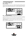
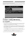
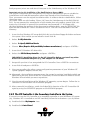
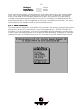
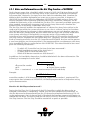
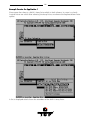
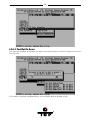
%/RDGLQJ*'76(783
As already mentioned before, there are two different possibilities to load GDTSETUP. Basically, these two possibilities are based on two different variants of the same program: One
which is integrated into the FLASH-RAM of the ICP Controller and another with is simply
an EXE program loadable under MS-DOS.
Loading GDTSETUP from the FLASH-RAM is very comfortable, since it requires nothing
else, but pressing the <CTRL><G> key combination after switching on the PC.
Loading GDTSETUP under MS-DOS becomes necessary, when you want to use GDTSETUP's
integrated partitioning functions, or when you have totally disabled the ICP's BIOS (which
includes the GDTSETUP variant loadable from FLASH-RAM).
If you want to load GDTSETUP under MS-DOS you have to load the device driver GDTX000
first. This can be done in two ways:
1. Starting the device driver from the DOS-command level by typing GDTX000<ENTER>
2. Starting the device driver automatically by means of the CONFIG.SYS
(DEVICE=GDTX000.EXE)
Note: GDTSETUP as well as GDTX000 are on the ICP CDROM.
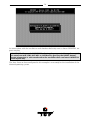
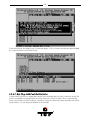
The header of the GDTSETUP program indicates with a letter after the version number,
whether GDTSETUP was loaded from disk or from Flash-RAM:
"R" for GDTSETUP loaded from the Flash-RAM after switching on the computer
"D" for GDTSETUP loaded from Disk, i.e., under MS-DOS.
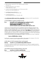
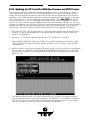
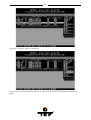
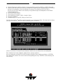
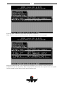
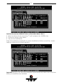
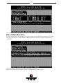
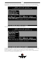
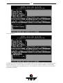
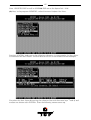
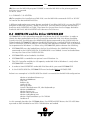
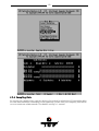
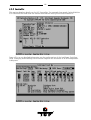
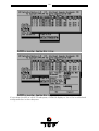
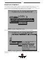
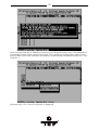
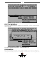
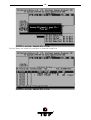
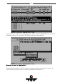
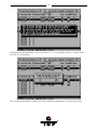
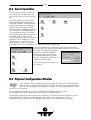
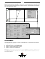
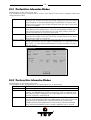
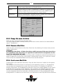
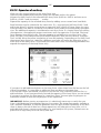
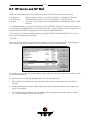
The main menu appears. Select Controller.
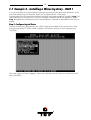
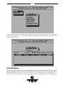
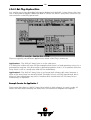
53
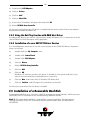
Select the ICP Controller and press <ENTER>.
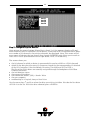
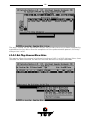
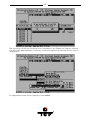
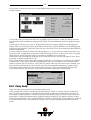
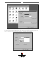
Press the <F2>-key for the Advanced Setup.
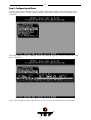
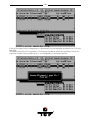
54
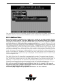
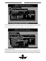
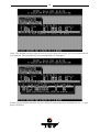
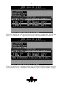
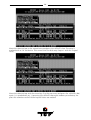
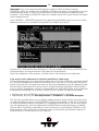
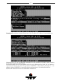
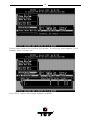
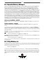
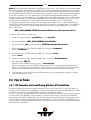
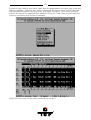
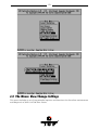
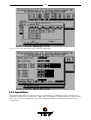
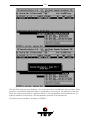
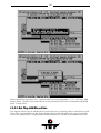
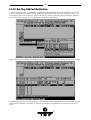
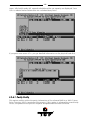
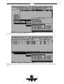
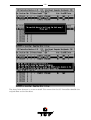
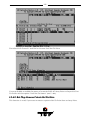
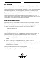
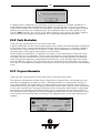
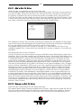
Select Configure Controller and press <ENTER>.
The fields can be selected by moving the cursor keys Ç and È . The values can be changed
by pressing <ENTER> and selecting a new setting. Leave this menu by pressing the <ESC>key. In order obtain optimum performance from your ICP Controller, it is essential that the
Cache and the Delayed Write options of the ICP Controller are set 21, too. If you should find
different settings here, we recommend that they be changed now.
55
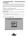
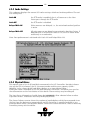
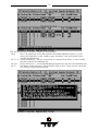
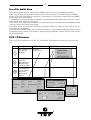
%8SGDWLQJWKH,&3&RQWUROOHU:LWK1HZ)LUPZDUHDQG%,269HUVLRQV
The firmware, the BIOS and the GDTSETUP program of the ICP Controller are stored in a
Flash-RAM which is part of the ICP Controller hardware. In contrast to EPROMs, FlashRAMs can be re-programmed many times and without the complicated UV-light erasing
procedure. Thus, both software modules can be easily updated without having to remove
the controller from its PCI slot. Firmware and BIOS are part of the *'7B53): file. The file
has an extension (e.g., GDT_RPFW.009) which indicates the version stepping. The latest
version of the this file can be downloaded either from our 24h BBS (+49-(0)-7131-5972-15)
or from our Website http://www.icp-vortex.com. We recommend that you also download the
packed files which contain the latest programs/drivers for the operating system used on
your system. Observe the following order when carrying out the updating procedure:
1. Get the latest GDT_RPFW file for the ICP Controller (download it from our BBS, or our
Website, or ask for an upgrade disk if you do not have a modem). The file does NOT
need to be expanded !
2. Format a 3.5" HD disk (1.44MB) and copy the GDT_RPFW file on this disk.
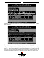
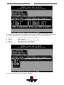
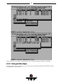
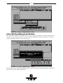
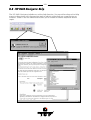
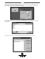
3. After loading GDTSETUP (from Flash-RAM or from disk under MS-DOS) select the desired ICP Controller for the firmware update and press the <F2>-key to enter the Advanced Setup.
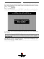
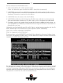
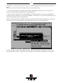
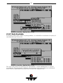
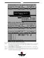
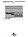
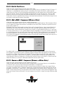
4. Select Configure Controller and thereafter Firmware Update. Insert the disk with the firmware
file into drive A. GDTSETUP loaded from the Flash-RAM will display a list of the valid
files found on the disk. If you have loaded GDTSETUP from disk you have to enter the
path "A:", first.
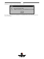
5. The update process starts as soon as the desired GDT_RPFW file has been selected.
Strictly observe the messages and instructions of GDTSETUP. It is extremely important
that the system is not switched off or reset during the update process. It is very likely
that this would cause the ICP Controller to become inoperable.
56
The new versions of the ICP Firmware, the BIOS and GDTSETUP are available after the next
cold-boot. All user-setting within GDTSETUP remain valid after the update process.
%$GGLWLRQDO1RWHV
Before the computer is switched off or a hard reset is carried out, the ICP Controller first has
to write the current contents of its cache RAM back to the hard disk(s) (flush). The computer
may only be switched off or reset after all hard disk accesses have been completed. If this is
not observed there is a high risk of data corruption and data loss ! A good indication for hard
disk activity is the front HDD-LED of your computer system (presuming it is connected with
the corresponding pin grid header of the ICP PCB). In addition, all ICP drivers (i.e. for all
supported operating systems) are designed to perform a cache flush when a regular system
shutdown is initiated (e.g., Under NetWare: Down and Exit; Under DOS: CTRL-ALT-DEL; Under UNIX: Shutdown). They will show a message similar to the following "Flushing Controller
Cache". As long as this message is displayed you must not switch off or reset your PCI computer. For Windows 95, Windows NT and OS/2 you may switch off or reset the computer as
soon as the operating system message is displayed, which indicates that it is safe, to turn
off the computer now.
The RISC CPU of the ICP Controller is equipped with a cooler. The cooler keeps the operating temperature of the CPU within the specified limits. The air intake is on the top of the
fan. The air flows through the fins of the heat sink and leaves it on the left and right side. In
addition, it is necessary that the whole ICP Controller is positioned in a constant airflow.
Normally, good server enclosures have extra fans for the motherboard expansion slot area.
In case of over temperature, the ICP Controller sends a message to the operator.
The cooler on your ICP Controller may look different from the one on pages of this manual.
Depending on the type of i960 Rx CPU installed on the ICP Controller, with some models, the
cooler is completely missing. This is intended !
All variants fully comply to the specifications laid down in this User's Manual.
57
&KDSWHU&
4XLFN6HWXS
58
&4XLFN6HWXS
&:KDWLVWKH$LPRI4XLFN6HWXS"
In the previous chapter we installed the ICP Controller in a PCI computer and connected
the SCSI and FCAL devices. Now these devices must be prepared in order to run with your
operating system. This Quick-Setup chapter should help you to get started quickly. QuickSetup shows four examples on how a single hard disk, a Mirroring Array Drive (RAID 1), a
RAID 5 Array Drive and a RAID 5 Array Drive with a Hot Fix drive are installed:
Example 1
Example 2
Example 3
Example 4
Installing a single hard disk.
Installing a Mirroring Array Drive (RAID 1), consisting of 2 hard disks.
Installing a RAID 5 Array Drive, consisting of 3 identical hard disks.
Installing a RAID 5 Array Drive, consisting of 3 identical hard disks, and
adding one Hot Fix hard disk.
With examples 3 and 4 some essential issues having direct impact on the structure and
configuration of an Array Drive will also be discussed:
1.
How many physical hard disks are to be integrated in the Array Drive ?
2.
Which redundancy level ought to be achieved ?
3.
Should the ICP Controller automatically recover redundancy in the event of
a disk failure ? Or, in other terms: Are Hot Fix drives needed ?
Before we go through these examples step by step, we would like to explain a few terms
and relations important for the basic understanding of the ICP Controller firmware. At the
end of example 4, we will try to answer the three questions above.
&:KDWLVWKH,&3&RQWUROOHU)LUPZDUH"
We refer to firmware (RAIDYNE®) as the operating system which controls the ICP Controller with all its functions and capabilities. The firmware exclusively runs on the ICP Controller and is stored in the Flash-RAM on the ICP Controller PCB. The controlling function is
entirely independent of the PCI computer and the host operating system installed (for example UNIX), and does not "drain" any computing power or time from the PCI computer. In
addition to disk chaining, RAID 0 and RAID 1, the firmware allows you to install and control
Array Drives of the types RAID 4 (data striping with dedicated parity drive), RAID 5 (data
striping with distributed parity) and RAID 10 (a combination between RAID 0 and 1). All ICP
Controllers are equipped with a hardware which is particularly well suited for disk arrays.
RAIDYNE® uses this hardware with extreme efficiency and therefore allows you to configure disk arrays that do not load the host computer (whereas all software-based RAID solutions more or less reduce the overall performance of the host computer.).
The basic concept of the RAIDYNE® is strictly modular, and consequently,
in its functioning it appears to the user as a unit construction system.
59
&7KH'LIIHUHQW5$,'/HYHOV
5$,''DWD6WULSLQJ
According to the adjusted stripe size (e.g., 16 KB) and the number of hard disks, the data
blocks are split into stripes. Each stripe is stored on a separate hard disk. Especially with
sequential read and write operations, we can observe a significant improvement of the data
throughput. RAID 0 includes no redundancy at all, i.e., when one hard disk fails, all data is
lost.
5$,''LVN0LUURULQJ'LVN'XSOH[LQJ
All data is stored twice on two identical hard disks. When one hard disk fails, all data are
immediately available on the other without any impact on the performance and data integrity.
We talk about "Disk Mirroring" when two hard disks are mirrored on one I/O channel. If each
hard disk is connected with a separate I/O channel, this is called "Disk Duplexing"
(additional security).
RAID 1 represents an easy and highly efficient solution for data security and system availability. It is especially suitable for installations which are not too large (the capacity available is only half of the installed capacity).
60
5$,''DWD6WULSLQJ:LWKD'HGLFDWHG3DULW\'ULYH
RAID 4 works in the same way as RAID 0. The data are striped amongst the hard disks. Additionally, the controller calculates redundancy data (parity information) which are stored
on a separate hard disk (P1, P2, ...). Even when one hard disk fails, all data are still fully
available. The missing data is recalculated from the data still available and the parity information. Unlike in RAID 1, only the capacity of one hard disk is needed for the redundancy. If we consider, for example, a RAID 4 disk array with 5 hard disks, 80% of the
installed hard disk capacity is available as user capacity, only 20% is used for redundancy.
In situations with many small data blocks, the parity hard disk becomes a throughput bottle-neck. With large data blocks, RAID 4 shows significantly improved performance.
5$,''DWD6WULSLQJZLWK6WULSHG3DULW\
Unlike RAID 4, the parity data in a RAID 5 disk array are striped in all hard disks. The RAID 5
disk array delivers a balanced throughput. Even with small data blocks, which are very likely
in a multi-tasking and multi-user environment, the response time is very good. RAID 5 offers the same level of security as RAID 4. When one hard disk fails, all data are still fully
available, the missing data are recalculated from the data still available and the parity information. RAID 4 and RAID 5 are particularly suitable for systems with medium to large
capacity requirements, due to their efficient ratio of the installed and actually available capacity.
61
5$,'&RPELQDWLRQRI5$,'DQG5$,'
The idea behind RAID 10 is simply based on the combination of RAID 0 (Performance) and
RAID 1 (Data Security). Unlike RAID 4 and RAID 5, there is no need to calculate parity information. RAID 10 disk arrays offer good performance and data security. As in RAID 0, optimum performance is achieved in highly sequential load situations. Identical to RAID 1,
50% of the installed capacity is lost for redundancy.
62
&+RZDUHWKH,&3)LUPZDUH)HDWXUHV$FWLYDWHG"
Any installation or maintenance procedures regarding the ICP Controller should be carried
out with the configuration program GDTSETUP. The monitoring programs GDTMON
(character oriented tool) and ICP RAID Navigator (GUI tool) allow a continuous monitoring and maintenance of the ICP Controller and the connected disk arrays. These utilities
also includes options to replace a defective drive with a new one (Hot Plug) and is available
for most of the operating systems supported by the ICP Controllers. GDTSETUP allows you
to set up single disks or complex disk arrays with simple and user-friendly installation procedures. Little previous knowledge is needed to be able to use GDTSETUP efficiently. It is
only necessary to understand the hierarchy levels in the ICP Controller firmware.
For the user's convenience the GDTSETUP program is available in two different variants:
GDTSETUP loaded from the ICP Controller's Flash-RAM after switching on the computer
GDTSETUP loaded from disk under MS-DOS.
The header of the GDTSETUP program indicates with a letter after the version number
whether GDTSETUP was loaded from disk or from Flash-RAM:
"R" for GDTSETUP loaded from the Flash-RAM after switching on the computer
"D" for GDTSETUP loaded from Disk, i.e., under MS-DOS.
Loading GDTSETUP with <CTRL><G> from the Flash-RAM is very comfortable since no operating system is required to carry out the configuration and setup works.
On the other side, loading GDTSETUP from disk (i.e., under MS-DOS) becomes necessary
for tasks like partitioning or enabling a totally disabled ICP BIOS (which includes
GDTSETUP).
&7KH([SUHVV6HWXS)XQFWLRQRI*'76(783
Whenever you load GDTSETUP and select the desired ICP Controller, it comes up in its
EXPRESS Setup mode. This mode does not require any previous knowledge. If you choose
this function, GDTSETUP carries out the complete installation entirely on its own, providing you for example with a fully operational RAID 5 Array Drive with optimized settings (for
instance, with all features of a given drive activated).
63
After selecting Configure Host Drives, select Create new Host Drive.
GDTSETUP scans the system for "free" hard disks (i.e., drives which are not yet part of other
Host Drives). Use the <SPACE>-bar to select the desired hard disks (they are marked with
an "*"). On the right side GDTSETUP offers highlighted the possible configurations with
these drives.
64
Pressing <ENTER> ends the selection.
After choosing a configuration type for an Array Drive, GDTSETUP displays a security request.
65
After this confirmation you can adjust the capacity per drive used for the disk array.
66
Express Setup delivers a fully operational RAID5 disk array.
After leaving GDTSETUP the parity information is generated.
For chapter C, we do not use this function, but give detailed instructions on how to set up a
single disk and disk arrays with GDTSETUP and its Enhanced Setup.
&/HYHOVRI+LHUDUFK\:LWKLQWKH,&3)LUPZDUH
RAIDYNE® is based on four fundamental levels of hierarchy. Each level has its "own drives"
( = components). The basic rule is:
To build up a "drive" on a given level of hierarchy, the "drives" of the next lower level
of hierarchy are used as components.
/HYHO
(1)
Physical Drives = hard disks, removable hard disks, some MO drives are located on the
lowest level. This can be either devices with a SCSI interface, or devices with a Fibre Channel Arbitrated Loop (FCAL) port.
They are the basic components of all "drive constructions" you can set up. However, before
they can be used by the firmware, these hard disks must be "prepared", a procedure we call
initialization. During this initialization each hard disk receives information which allows a
univocal identification even if the SCSI-ID, FCAL-ID or the controller is changed. For reasons of data coherency, this information is extremely important for any drive construction
consisting of more than one physical drive.
/HYHO
On the next higher level are the Logical Drives. Logical Drives are introduced to obtain full
independence of the physical coordinates of a physical device. This is necessary to easily
change the whole ICP Controller and the channels, IDs, without loosing the data and the
information on a specific disk array.
(1)
Also see section C.5.
67
/HYHO
On this level of hierarchy, the firmware forms the Array Drives. This can be:
Single Disks (one hard disk, some vendors call it JBOD – "Just A Bunch Of Drives")
Chaining Sets (concatenation of several hard disks)
RAID 0 Array Drives
RAID 1 Array Drives, RAID 1 Array Drives plus hot fix drive
RAID 4 Array Drives, RAID 4 Array Drives plus hot fix drive
RAID 5 Array Drives, RAID 5 Array Drives plus hot fix drive
RAID 10 Array Drives, RAID 10 Array Drives plus hot fix drive
/HYHO
On the highest level of hierarchy, the firmware forms the Host Drives. In the end, only
these Host Drives can be accessed by the host operating system of the computer. Drives C,
D, etc. under MS-DOS, Windows NT, NetWare, etc. are always referred to as Host Drives by
the firmware. The firmware automatically transforms each newly installed Logical Drive and
Array Drive into a Host Drive. This Host Drive is then assigned a Host Drive number which
is identical to its Logical Drive or Array Drive number.
The firmware is capable of running several Host Drives of the most various kinds at the
same time. An example for MS-DOS: drive C is a RAID 5 type Host Drive (consisting of 5
hard disks), drive D is a single hard disk, and drive E is a CDROM communicating with
RAIDYNE® through corelSCSI and the ICP ASPI manager.
On this level the user may split an existing Array Drive into several Host Drives.
After a capacity expansion of a given Array Drive the added capacity appears as a new Host
Drive on this level. It can be either used as a separate Host Drive, or merged with the first
Host Drive of the Array Drive.
Within GDTSETUP, each level of hierarchy has its own special menu:
/HYHO
/HYHO
/HYHO
/HYHO
Ö
Ö
Ö
Ö
Menu: Configure Physical Devices
Menu: Configure Logical Drives
Menu: Configure Array Drives
Menu: Configure Host Drives
Generally, each installation procedure passes through these 4 menus, starting with level 1.
Therefore:
First initialize the Physical Drives.
Then configure the Logical Drives.
Then configure the Array Drives (e.g. Array Drives with RAID 0, 1, 4, 5
and 10).
Finally, configure the Host Drives.
&8VLQJ&'520V'$7V7DSHVHWF
A SCSI device that is not a SCSI hard disk or a removable hard disk, or that does not behave
like one, is called a Not Direct Access Device.
Such a device is not configured with GDTSETUP and does not form a Logical or Host
Drive. SCSI devices of this kind are either operated through the ASPI interface (Advanced
SCSI programming Interface) (MS-DOS, Windows, Novell NetWare or OS/2), or are directly
accessed from the operating system (UNIX, Windows NT). For more information on how to
68
use these devices, please refer to the corresponding chapters of this manual. Note: hard
disks and removable hard disks are called Direct Access Devices. However, there are some
Not Direct Access Devices, for instance certain MO drives, which can be operated just like removable hard disks if they have been appropriately configured before (for example by
changing their jumper setting).
But enough on the dry theory. Now here are the examples which explain step by step
all the necessary basics for setting up Host Drives with your ICP Controller
&([DPSOH,QVWDOOLQJD6LQJOH+DUG'LVN
We presume that the controller and the hard disks have been installed properly.
6WHS/RDGLQJ*'76(783
You can load GDTSETUP in two ways:
1. Press the <CTRL><G> key combination when the ICP BIOS message comes up (shortly
after switching on the computer) and load GDTSETUP from the Flash-RAM of the ICP
Controller. In this case no operating system is required.
If GDTSETUP was loaded this way, there is an "R" (ROM) behind the version number.
2. Load GDTSETUP from disk under MS-DOS. Boot the MS-DOS-operating system (either
from a boot-floppy or from an already existing boot drive, i.e., IDE-hard disk etc.). In order for GDTSETUP to work properly, you have to load the device driver GDTX000 first.
This can be done in two ways:
a.) Load GDTX000 from the DOS-command level by typing in GDTX000<ENTER>
b.) Load GDTX000 automatically through the CONFIG.SYS file (DEVICE=GDTX000.EXE)
Note: GDTSETUP.EXE as well as GDTX000.EXE are on the System Disk - DOS.
If GDTSETUP was loaded this way, there is a "D" (Disk) behind the version number.
You may now ask what are the differences between the two GDTSETUP variants ?
They are small. The GDTSETUP variant loadable from disk under MS-DOS also additionally
allows the partitioning of Host Drives, which is not possible with GDTSETUP loaded from
the Flash-RAM. Loading GDTSETUP from the Flash-RAM is pretty easy, since there is
nothing more required to configure the disk arrays. User's, who have for instance, an NT
installation without a DOS partition, will highly appreciate this Flash-RAM-resident
GDTSETUP.
For our example, it is not relevant whether we load GDTSETUP from the Flash-RAM, or from
disk.
Now load GDTSETUP. The first menu asks you to select the desired ICP Controller. In our
example, there is only one ICP Controller installed in the system. Therefore, simply press
<ENTER> and then <F2> to select the Advanced Setup.
69
The main menu gives you the following options. As mentioned before, we have to go
through levels 1 to 4 to install the hard disk (with almost nothing to do on levels 3 and 4).
/HYHO
/HYHO
/HYHO
/HYHO
6WHS&RQILJXUH3K\VLFDO'HYLFHV
Now activate the menu Configure Physical Devices (level 1). A list appears showing all hard
disks found on the ICP Controller’s I/O channels. If you have an ICP Controller with a different number of I/O channels, the existing channels are displayed. Note: This screen will always report all devices that are found, even though GDTSETUP only allows you to work on
Direct Access Devices (and therefore not on tape drives, DATs, CD ROMs etc.).
The screen shows you:
70
the I/O channel to which a device is connected (this can be a SCSI or a FCAL channel)
which ID the drive has (the entry I/O Processor stands for the corresponding I/O channel
of the ICP Controller. It has the default ID setting 7 for SCSI and 125 for FCAL).
The IDs of the FCAL drives are normally assigned through the backplane of the Fibre
Channel Enclosure.
the initialization status
the names of the drives
the Read-Write-Status. [RW] = Read + Write
the gross capacity
membership in a Logical, Array or Host Drive
Use the cursor keys n and p to select the drive you wish to initialize. We take the first drive
of FCAL-A in the list. With this drive selected, press <ENTER>.
(Note: On SCSI-A, ID 0 and ID 6 are devices which are not relevant for our examples).
The Configure Disk menu appears which shows various options.
For our example we choose the SCSI Parameter/Initialize menu option and press <ENTER>.
The parameters within this menu can be changed by pressing <ENTER> and selecting the
new setting.
71
With Fibre Channel devices, there are only view settings which are relevant. They should be
"On" or "Enabled". (Note: Fibre Channel devices are also controlled by the SCSI protocol.)
With "real" SCSI devices, there are more parameters to describe the device.
1. Sync. Transfer: Enable
The SCSI-bus allows an asynchronous and a synchronous transfer. Every SCSI device must
be able to perform the first type of transfer, the second one is optional. The advantage of
the synchronous transfer lies in a higher data transfer rate as the signal transfer times on
the possibly long SCSI-cable have no influence on the transfer rate anymore. Two SCSI-bus
72
participants wanting to exchange data between each other have to check if and how (i.e.,
with which parameters) a synchronous data transfer between them is possible. Therefore,
the mere setting does not automatically enable synchronous data transfer; this mode is
only effective if both devices support it and after they have checked their capability of
communicating with each other in this mode.
2. Sync. Transfer Rate
The maximum synchronous transfer rate can be limited. This limitation may become necessary if a particular SCSI cabling does not allow the maximum rate the drive and the controller could achieve. In our example, we leave the rate at 20.0 MB/s (for Wide SCSI at 20.0
MB/s and Wide & Ultra SCSI at 40.0 MB/s).
Note: In order to select a transfer rate above 10.0 MB/s the Protocol has to be set to SCSIIII.
3. Disconnect: Enable
The concept of the SCSI-bus allows several participants (8 IDs with 8 LUNs each). All these
participants should be able to use the bus in a manner that causes the least reciprocal disturbance or obstruction. A participant should therefore vacate the bus if he does not need
it. For reasons of performance, it is particularly important to guarantee a high degree of
overlapping of the actions on the SCSI-bus. This high degree of overlapping can be
achieved if a SCSI device is allowed to disconnect, thus leaving the bus to be used by other
participants. If there is only one SCSI device connected to the SCSI-bus, Disconnect should
be disabled.
4. Protocol
This can be either SCSI-II or SCSI-III.
If you select SCSI-III make sure, that your hard disk supports this protocol. Most new multiGB hard disks support SCSI-III. To enable Ultra (FAST-20) transfer rates (Narrow: 20 MB/s;
Wide: 40 MB/s) SCSI-III protocol is required.
5. Disk Read Cache / Disk Write Cache / Tagged Queues
If a drive supports particular SCSI features you enable them (On).
Note: Most of the modern drives support disk caching (read and write). Some do not support Tagged Queues.
Press <ESC> to leave the SCSI Parameter/Initialize menu.
GDTSETUP displays a warning on the destruction of all data. This implies two different
evaluations, according to the drive’s current state and the options you have selected:
1. First Initialization of the device.
In this case the warning must be taken seriously. If the drive was previously connected to
a different controller (e.g., NCR etc.) and still contains data, this data will be lost now.
2. The device was already initialized.
If only internal parameters, such as Disconnect, Synchronous Transfer and SCSI-II options have been changed, the data on the drive remains intact. Only the function state of
the device is changed.
73
Press <Y> and we are back on the main screen of level 1 and see that the initializationstatus of the device has changed.
6WHS&RQILJXUH/RJLFDO'ULYHV
We now leave level 1 (by pressing the <ESC>-key) and are back in the main menu. Now,
with the cursor keys n and p select Configure Logical Drives and go to level 2 by pressing
<ENTER>.
74
The main screen of level 2 appears. Move the selection bar to Create new Logical Drive and
press <ENTER> .
Note: The already existing Logical Drive in this list has no relevance for our example.
75
Select the initialized hard disk with the <SPACE>-bar (it becomes marked with an "*") and
press <ENTER>.
For security reasons, you will be asked again if you want to use the selected disk to create a
Logical Drive.
As we are sure of our choice, we confirm with <Yes>. GDTSETUP allows you to limit the
hard disk size for this Logical Drive. This becomes interesting when you configure disk arrays. For this example we use the full capacity and press <ENTER> .
76
The dialog box is closed and we are back in the main menu of level 2.
As you can see, we have already created a new Logical Drive of the type Disk. The name of
the Logical Drive is assigned automatically and contains the channel description and the
I/O channel ID after the "_" . This can serve as a reminder when you install a complex system with many drives. (Naturally, you may change the name.)
This concludes the installation on level 2. Now press the <ESC>-key to leave this screen.
Since we have only a single disk assigned to a Logical Drive, there is nothing to do in the
Configure Array Drives menu, thus we go directly to the Configure Host Drives menu and have no
Step 4.
77
6WHS&RQILJXUH+RVW'ULYHV
We are now back in the main menu of GDTSETUP and select Configure Host Drive.
The main screen of level 4 appears. Press <ENTER> . A list of available Host Drives is displayed. Again, the first entry is not relevant for our example.
At the second position we find our previously configured Logical Drive. It was automatically
transformed into a Host Drive, thus for this example we have nothing to do in this menu.
Press <ENTER> to get a list of possible menu options.
We should not forget to mention, that if you would have selected Create new Host Drive, this
would have lead you to the same menu as the Express Setup mode.
But this example is an exercise which should help you to gain a better understanding of
how the ICP Controller and GDTSETUP work. So don't believe we let you do redundant
homework.
By the way, if you have loaded GDTSETUP from the Flash-RAM (<CTRL><G>) the Partition
Drive option will be missing in this menu. The reason is that partitioning makes no sense
when there is not an operating system loaded and the INT13H extension of the ICP Controller has not yet been activated.
6WHS/HDYLQJ*'76(783
We are now back in the main menu of GDTSETUP. The installation is completed, and we
therefore leave GDTSETUP by pressing the <ESC>-key. The following message appears:
78
As we are done with the installation and therefore definitely want to leave GDTSETUP, we
press any key.
IMPORTANT: Always end GDTSETUP by leaving the program in the regular way (do
not warm-boot with CTRL-ALT-DEL or cold boot by pressing the RESET button).
Certain information is only transferred to the controller when you leave GDTSETUP
in the regular way.
The Host Drive we have configured in this example is now ready for the installation of the
desired operating system.
79
&([DPSOH,QVWDOOLQJD0LUURULQJ$UUD\5$,'
It is our intention to install a Mirroring Array consisting of two identical hard disks. In the
classical terminology of the RAID levels this is called a RAID 1 disk array.
We presume that the controller and the hard disks have been properly installed. Step 1 of
the installation is the same as in the first example, therefore we do not explain it again.
Step 2 regards the initialization of the second device. Proceed as described in the first example.
6WHS&RQILJXUH/RJLFDO'ULYHV
We now leave level 1 (by pressing the <ESC>-key) and are back in the main menu. Now,
with the cursor keys n and p select Configure Logical Drives and go to level 2 by pressing
<ENTER>.
The main screen of level 2 appears. Move the selection bar to Create new Logical Drive and
press <ENTER> .
80
Note: The already existing Logical Drive in the first position of this list has no relevance for
our example. The second entry was created before in Example 1.
Select the initialized hard disk with the <SPACE>-bar (it becomes marked with an "*") and
press <ENTER>.
81
For security reasons, you will be asked again if you want to use the selected disk to create a
Logical Drive.
As we are sure of our choice, we confirm with <Yes>. GDTSETUP allows you to limit the
hard disk size for this Logical Drive. This becomes interesting when you configure disk arrays. For this example we use the full capacity and press <ENTER> .
The dialog box is closed and we are back in the main menu of level 2.
82
As you can see, we have created another Logical Drive of the type Disk. The name of the
Logical Drive is assigned automatically and contains the channel description and the I/O
channel ID after the "_" . This can serve as a reminder when you install a complex system
with many drives. (Naturally, you may change the name.)
This concludes the installation on level 2. Now press the <ESC>-key to leave this screen.
In the next step it is our objective to add the third Logical Drive in this list as a mirroring
partner to the second Logical Drive of the list, thus configuring a RAID 1 disk array.
6WHS&RQILJXUH$UUD\'ULYHV
We now leave level 2 (by pressing the <ESC>-key) and are back in the main menu. Now,
with the cursor keys n and p select Configure Array Drives and go to level 3 by pressing
<ENTER>.
83
Since we want to create a new Array Drive press <ENTER>.
Note: The first entry in the following list has no relevance for our example.
Move the selection bar to the second entry and press the <SPACE>-bar. The entry is
marked with an "M" for Master. This means that the data from this Logical Drive are copied
to the second Logical Drive, which we will select next.
84
Move the selection bar with the cursor key p to the next entry and press the <SPACE>-bar,
again. It is marked with an "*"(pressing the <SPACE>-bar again undoes your choice).
When the Logical Drive is selected, confirm with <ENTER>. GDTSETUP displays now a list
of possible RAID levels, available with the number of Logical Drives selected. In our case it
is RAID 0 (data striping) and RAID 1. Move the selection bar to RAID-1 and press <ENTER>.
85
GDTSETUP displays a security request, which we answer with <Y>.
As you can easily recognize, we have created a new Array Drive of the Type RAID-1. Its state
is build. When we leave GDTSETUP at the end of this example, you will see that the ICP
Controller automatically copies the data of the first Logical Drive (our master) to the second Logical Drive. During this synchronization the RAID-1 array is fully operational.
The functioning of a RAID-1, or mirroring, disk array, is easy to understand: On the ICP Controller, one write-access from the host computer is transformed into two write-accesses (to
both Logical Drives forming the mirroring array). If the two Logical Drives are built of hard
disks, which are connected with different I/O channels of the ICP Controller, both write-
86
accesses are performed simultaneously (this method is often called Disk Duplexing). During
a read-access of the host computer the data will be read from the Logical Drive whose hard
disk has the fastest access to the data requested.
If a hard disk should fail (for instance due to a mechanical defect), all data is still available
on the other Logical Drive. In this event, the controller gives an acoustical alarm.
Steps 5 and 6 are the same as in example 1.
&([DPSOH,QVWDOOLQJD5$,''LVN$UUD\
We presume that the controller and the hard disks have been installed properly.
6WHS/RDGLQJ*'76(783
You can load GDTSETUP in two ways:
1. Press the <CTRL><G> key combination when the ICP BIOS message comes up (shortly
after switching on the computer) and load GDTSETUP from the Flash-RAM of the ICP
Controller. In this case no operating system is required.
If GDTSETUP was loaded this way, there is an "R" (ROM) behind the version number.
2. Load GDTSETUP from disk under MS-DOS. Boot the MS-DOS-operating system (either
from a boot-floppy or from an already existing boot drive, i.e., IDE-hard disk etc.). In order for GDTSETUP to work properly, you have to load the device driver GDTX000 first.
This can be done in two ways:
a.) Load GDTX000 from the DOS-command level by typing in GDTX000<ENTER>
b.) Load GDTX000 automatically through the CONFIG.SYS file (DEVICE=GDTX000.EXE)
Note: GDTSETUP.EXE as well as GDTX000.EXE are on the System Disk - DOS.
If GDTSETUP was loaded this way, there is a "D" (Disk) behind the version number.
You may now ask what are the differences between the two GDTSETUP variants ?
87
They are small. The GDTSETUP variant loadable from disk under MS-DOS also additionally
allows the partitioning of Host Drives, which is not possible with GDTSETUP loaded from
the Flash-RAM. Loading GDTSETUP from the Flash-RAM is pretty easy, since there is
nothing more required to configure the disk arrays. User's, who have for instance, an NT
installation without a DOS partition, will highly appreciate this Flash-RAM-resident
GDTSETUP.
For our example, it is not relevant whether we load GDTSETUP from the Flash-RAM, or from
disk.
Now load GDTSETUP. The first menu asks you to select the desired ICP Controller. In our
example, there is only one ICP Controller installed in the system. Therefore, simply press
<ENTER> and then <F2> to select the Advanced Setup.
The main menu gives you the following options. As mentioned before, we have to go
through levels 1 to 4.
88
/HYHO
/HYHO
/HYHO
/HYHO
6WHS&RQILJXUH3K\VLFDO'HYLFHV
Now activate the menu Configure Physical Devices (level 1). A list appears showing all hard
disks found on the ICP Controller’s I/O channels. If you have an ICP Controller with a different number of I/O channels, the existing channels are displayed. Note: This screen will always report all devices that are found, even though GDTSETUP only allows you to work on
Direct Access Devices (and therefore not on tape drives, DATs, CD ROMs etc.).
The screen shows you:
the I/O channel to which a device is connected (this can be a SCSI or a FCAL channel)
which ID the drive has (the entry I/O Processor stands for the corresponding I/O channel
of the ICP Controller. It has the default ID setting 7 for SCSI and 125 for FCAL).
The IDs of the FCAL drives are normally assigned through the backplane of the Fibre
Channel Enclosure.
the initialization status
the names of the drives
the Read-Write-Status. [RW] = Read + Write
the gross capacity
membership in a Logical, Array or Host Drive
Use the cursor keys n and p to select the drive you wish to initialize. We take the first drive
of FCAL-A in the list. With this drive selected, press <ENTER>.
89
(Note: On SCSI-A, ID 0 and ID 6 are devices which are not relevant for our examples).
The Configure Disk menu appears which shows various options.
For our example we choose the SCSI Parameter/Initialize menu option and press <ENTER>.
The parameters within this menu can be changed by pressing <ENTER> and selecting the
new setting.
With Fibre Channel devices, there are only view settings which are relevant. They should be
"On" or "Enabled". (Note: Fibre Channel devices are also controlled by the SCSI protocol.)
90
Press <ESC> to leave the SCSI Parameter/Initialize menu.
GDTSETUP displays a warning on the destruction of all data. This implies two different
evaluations, according to the drive’s current state and the options you have selected:
1. First Initialization of the device. In this case the warning must be taken seriously. If the drive
was previously connected to a different controller (e.g., NCR etc.) and still contains
data, this data will be lost now.
2. The device was already initialized. If only internal parameters, such as Disconnect, Synchronous Transfer and SCSI-II options have been changed, the data on the drive remains intact. Only the function state of the device is changed.
Press <Y> and we are back on the main screen of level 1 and see that the initializationstatus of the device has changed.
91
Initialize the next two SEAGATE drives as described above, that is:
Select the device with the cursor keys n and p and press the <ENTER>-key
Choose the settings shown above
Carry out the initialization
When the initialization completed, the screen should look as follows (a small i (i = initialized) must follow the ID of each hard disk):
Important: Moving to the next level (Configure Logical Drives) only makes sense if all three
devices you need there are initialized.
92
6WHS&RQILJXUH/RJLFDO'ULYHV
We now leave level 1 (by pressing the <ESC>-key) and are back in the main menu. Now,
with the cursor keys n and p select Configure Logical Drives and go to level 2 by pressing
<ENTER>.
The main screen of level 2 appears. Move the selection bar to Create new Logical Drives and
press <ENTER> .
Note: The already existing Logical Drive in this list has no relevance for our example.
93
Select the initialized hard disk with the <SPACE>-bar (it becomes marked with an "*") and
press <ENTER>.
For security reasons, you will be asked again if you want to use the selected disk to create a
Logical Drive. As we are sure of our choice, we confirm with <Yes>. GDTSETUP allows you
to limit the hard disk size for this Logical Drive. This becomes interesting when you configure disk arrays and you want to make sure that future drives you want to bring into the disk
array (e.g., for the capacity expansion or for replacement purposes) fit. It would be bad luck
if the new drive only had 8537MB. GDTSETUP couldn't accept it. To avoid this occuring, you
could limit the capacity of each drive to 8000 MB. Any new 9 GB drive must have at least
94
this capacity. The difference in our example would be lost. For this example we use the full
capacity and press <ENTER> .
The dialog box is closed and we are back in the main menu of level 2.
As you can see, we have already created a new Logical Drive of the type Disk. The name of
the Logical Drive is assigned automatically and contains the I/O channel description and
the FCAL-ID after the "_" . This can serve as a reminder when you install a complex system
with many drives. (Naturally, you may change the name.). Now configure the remaining
Logical Drives one by one. After having completed these procedures for all three Logical
Drives, you will see the following screen:
95
This concludes the installation on level 2. Now press the <ESC>-key to leave this screen.
6WHS&RQILJXUH$UUD\'ULYHV
We now leave level 2 (by pressing the <ESC>-key) and are back in the main menu. Now,
with the cursor keys n and p select Configure Array Drives and go to level 3 by pressing
<ENTER>.
Since we want to create a new Array Drive press <ENTER>.
Note: The first entry in the next list has no relevance for our example.
96
Move the selection bar to the second entry and press the <SPACE>-bar. The entry is
marked with an "M" for Master. This means that the disk array "begins" with this Logical
Drive.
Move the selection bar with the cursor key p to the next entry and press the <SPACE>-bar,
again. It is marked with an "*"(pressing the <SPACE>-bar again undoes your choice). Repeat this selection until all three Logical Drives are marked.
97
When the last Logical Drive is selected, confirm with <ENTER>. GDTSETUP now displays a
list of possible RAID levels available with the number of Logical Drives selected.
RAID 0
RAID 1
RAID 4
RAID 5
RAID 10
pure data striping without redundancy
disk mirroring
data striping with dedicated parity drive
data striping with striped parity
RAID 0 combined with RAID 1
In our case we take RAID-5 and press <ENTER>.
98
GDTSETUP asks for the Stripe Size. This is the size of the stripes into which the data is divided. The default is 32KB which we leave for this example and therefore press <ENTER>.
(Note: 32KB stripe size is suggested because in various performance tests it has proved to
be the best value.). GDTSETUP displays a security request, which we confirm with <Y>.
GDTSETUP allows you to limit the capacity of the disk array. This may be of interest if your
installation requires an exact size for a disk array. Normally, the full capacity is used. In our
example we press <ENTER> .
99
It's done !
We succeeded in setting up a RAID 5 disk array. The screen shows that the disk array is currently in an build state. Later in this chapter, we shall explain the different states a
RAIDYNE® disk array can assume.
We are now back in the main menu of GDTSETUP.
6WHS&RQILJXUH+RVW'ULYHV
We are now back in the main menu of GDTSETUP and select Configure Host Drives.
The main screen of level 4 appears. Press <ENTER> . A list of available Host Drives is displayed. Again, the first entry is not relevant for our example.
100
At position 1 we find our previously configured RAID-5 disk array. It was automatically
transformed into a Host Drive, thus for this example we have nothing to do in this menu.
Press <ENTER> to get a list of possible menu options.
We should not forget to mention that if you would have selected Create new Host Drive, this
would have lead you to exactly the same menu as the Express Setup mode.
But this example is an exercise which should help you to gain a better understanding of
how the ICP Controller and GDTSETUP work.
101
By the way, if you have loaded GDTSETUP from the Flash-RAM (<CTRL><G>) the Partition
Drive option will be missing in this menu. The reason is that partitioning makes no sense,
when there is no operating system loaded and the INT13H extension of the ICP Controller
has not yet been activated.
6WHS/HDYLQJ*'76(783
We are now back in the main menu of GDTSETUP. The installation is completed, and we
therefore leave GDTSETUP by pressing the <ESC>-key. The following message appears:
As we are done with the installation and therefore definitely want to leave GDTSETUP, we
press any key.
IMPORTANT: Always end GDTSETUP by leaving the program in the regular way (do
not warm-boot with CTRL-ALT-DEL or cold boot by pressing the RESET button).
Certain information is only transferred to the controller when you leave GDTSETUP
in the regular way.
After rebooting the system, load GDTSETUP anew. Change to the Advanced Setup menu,
select Configure Array Drives, and press <ENTER> .
Select the Array Drive, press <ENTER> and move the selection bar to the Build/Rebuild progress menu. Press <ENTER> .
102
From the progress information slider, we can easily see, that the 17 GB disk array is already
built up 2% and that the estimated time for the build process is 43 minutes.
Note: During the build process the disk array is fully operational, but not yet redundant.
I.e., you could immediately start installing your desired operating system, without having
to wait until this process has finished.
At the end of this build process the disk arrays state becomes ready (fully redundant).
Now press <ENTER> and move the selection bar to the Parity Verify menu. Press <ENTER>.
103
RAIDYNE® now checks the correctness of the redundancy information (i.e., calculates the
redundancy information anew and compares it with the already existing information).
Depending on how large the disk array is, this check may take quite a long time, however, it
can be aborted by pressing <ESC>. Parity Verify is a diagnosis function which enables you to
verify the consistency of a disk array every now and then. We interrupt the verification by
pressing <ESC>. Note: The ICP monitor program GDTMON and the ICP RAID Navigator
also include the parity verify function. Unlike in GDTSETUP, the disk array’s parity can be
checked while the disk array is fully operational (e.g., in a NetWare file server).
6WHS6LPXODWLQJD'ULYH)DLOXUH
This part of our example is optional. Nevertheless, we recommend that you go through it. It
gives you a better understanding of how RAIDYNE® reacts in the event of a drive failure
and what you have to do in such a case.
Important: To carry out the drive failure simulation, the disk array must be in the ready state.
Only in this state, has the disk array redundancy.
In order to make the simulation as realistic as possible, we suggest creating an MS-DOSpartition on the disk array with FDISK. To create disk activity, write a small batch program
which copies data from one directory of this partition to another. While the copy process is
going on, we simulate a drive failure of drive DISK_B1 by removing the drive's DC power
supply cable. Now we can observe how RAIDYNE® reacts:
1. After a short time, the acoustical alarm of the ICP is activated. (Note: this alarm is only
activated when the RAID 5 Array Drive is being accessed).
2. RAIDYNE® activates the so-called fail operation state during which the disk array remains fully operational. The data of the failed drive is calculated by means of the redundant data stored on the other drives.
The alarm signal does not switch off because the disk array, although operational, is found
in a state without redundancy, that is, a state which should be eliminated as soon as possible. The alarm signal turns off when GDTSETUP is loaded.
104
How is this situation reflected in GDTSETUP ?
What has happened to the failed hard disk ?
To answer these questions, we load GDTSETUP and check. We go to the menu Configure Array Drives menu and select our RAID-5 disk array which entered the fail state. Press <F2> to
get further information on the failure.
After selecting the failed Logical Drive, press again <F2> to obtain detailed information on
the physical drive which has actually failed.
105
Important: Even if we reconnected the power supply to DISK_B1 before loading
GDTSETUP, DISK_B1 would not be included in the disk array again. If you decide to use the
failed hard disk again, it is best if you reconnect the drive to the power supply and do a
cold boot. After loading GDTSETUP select the Configure Array Drives menu. Select the Replace
Array Component menu
Press <ENTER> . GDTSETUP recognizes the previously failed drive again (it was not really
defective) and asks if it should be integrated into the disk array again.
Answer <Yes> and the disk array changes its state into rebuild. After leaving GDTSETUP the
controller begins the reconstruction of the data of the failed drive.
After the completion of this process, the disk array's state changes into ready again.
A few words on the replacement of a defective hard disk of a disk array.
If a hard disk belonging to a disk array for which no Hot Fix drive had been assigned should
fail, you should replace this defective hard disk with a new one as soon as possible. Always be
aware of the fact that this disk array does not have any redundancy until the defective hard
disk has been substituted. This means that if another hard disk should fail while the disk
array is without redundancy, all data is irretrievably lost. RAIDYNE® offers two possibilities
of replacing a failed drive of an array for which no Hot Fix drive has been designated:
1. Replacement with GDTSETUP (we have just demonstrated this method)
2. Replacement by using the Hot Plug function of GDTMON and ICP RAID Navigator
The Hot Plug method allows you to replace a defective drive while the disk array continues
to work and without having to load GDTSETUP. When this method is used, the I/O channel
to which the defective drive is connected, is temporarily halted (that is, for the time necessary for replacement). After the replacement RAIDYNE® automatically begins to rebuild
the new drive. The halting and release of the I/O channel is controlled by GDTMON or ICP
RAID Navigator. This halt of the I/O channel serves to avoid that interferences impair the
functioning of still intact drives on this channel.
106
We would like to stress that the Hot Fix method is by far the most secure method of
replacing a defective drive while the disk array is operational (see next example). First of
all, because it is completely automatic, and secondly because it does not imply any mechanical or electrical interventions on the disk array as the Hot Plug method does.
We shall explain GDTMON and the Hot Plug method more thoroughly later in this manual.
&([DPSOH5$,''LVN$UUD\V:LWKD+RW)L['ULYH
What we call Hot Fix drives is referred to as Host Spare drives in some literature. Most
part of the installation is carried out as in our third example, so we do not repeat the explanation.
Do Step 1, Step 2, Step 3 and Step 4 as described in example no. 3.
In addition, initialize the fourth Seagate drive and make a Logical Drive out of it.
6WHS&UHDWLQJD+RW)L['ULYH
Select the Array Drive in the Configure Array Drives menu and press <ENTER> . Move the selection bar to the Add Hot Fix Drive menu.
Press <ENTER>. GDTSETUP now displays a new dialog-box containing all the Logical
Drives apt to serve as a Hot Fix drive (one criterion for this suitability is the drive's capacity,
i.e., it has to be large enough). So do not be surprised if you do not find all the drives you
would have expected during later installations. GDTSETUP knows which drives are suitable
to be used as Hot Fix drives.
107
Press <ENTER>.
GDTSETUP offers two different Hot Fix types: A private Hot Fix drive is only available for one
specific disk array. A Hot Fix drive in a Hot Fix Pool can be made available to several disk
arrays (presuming that the capacity fits). In our example we choose the Private Hot Fix drive
and press <ENTER> .
108
Attention: By turning a Logical Drive into a Hot Fix drive, all its data is irretrievably lost.
After pressing <F2> we get detailed information on the structure of the disk array. The last
entry refers to the Priv. Hot Fix drive.
We have already seen this form before, with the only difference that DISK_B3 has been assigned to be the Hot Fix drive. We now leave GDTSETUP as described in example no. 3, in
order to allow GDTSETUP to send all relevant information to the controller and let
RAIDYNE® create and store the redundant information.
109
6WHS/HDYLQJ*'76(783
We are now back in the main menu of GDTSETUP. The installation is completed, and we
therefore leave GDTSETUP by pressing the <ESC>-key. The following message appears:
As we are done with the installation and therefore definitely want to leave GDTSETUP, we
press any key.
IMPORTANT: Always end GDTSETUP by leaving the program in the regular way (do
not warm-boot with CTRL-ALT-DEL or cold boot by pressing the RESET button).
Certain information is only transferred to the controller when you leave GDTSETUP
in the regular way.
The question that arises now is:
When and how does the Hot Fix mechanism work ?
Normally, RAIDYNE® puts Hot Fix drives in a stand-by mode, that is, their motors are
stopped. However, it may happen that certain operations such as loading drivers, starting
GDTSETUP and so on, cause the Hot Fix drives to start their motors. This takes a little Bit
longer, but it is necessary in order to enable RAIDYNE® to check the consistency of the
setup. RAIDYNE® substitutes a failed hard disk with a Hot Fix drive only if the array was in
a ready state before the failure. Or, in other words, a Hot Fix drive can only be activated if
the corresponding disk array was in a state of data redundancy at the moment of failure.
Important: The following partial step can only be performed if the disk array is in the ready
state.
6WHS6LPXODWLQJD+DUG'LVN)DLOXUH:KHQD+RW)L['ULYHLV3UHVHQW
This partial step is optional. However, we recommend that you carry it out in order for you
to get an idea of how RAIDYNE® reacts in such a situation and which steps need to be
taken. To have a very realistic simulation, create a DOS-partition and generate load on your
disk array by using a batch file with copy commands. During these copy operations we
cause DISK_B2 to fail by plugging out its power supply.
110
We now observe how RAIDYNE® reacts:
1. After a short while, ICP's alarm signal is heard.
(Note: the alarm only goes on when the RAID 5 Array Drive is accessed.)
2. RAIDYNE® activates the so-called fail operation mode. In this mode, the disk array remains fully operational. The data of the failed drive is reconstructed by means of the redundancy information stored on the other drives.
3. RAIDYNE® starts the motor of the Hot Fix drive.
4. RAIDYNE® includes the Hot Fix drive into the disk array and starts to reconstruct the
data and redundancy information. The disk array is now in the operation mode rebuild.
5. The alarm signal is not turned off until a new Hot Fix drive is added to the disk array, or
until GDTSETUP (or GDTMON) is loaded and the missing Hot Fix drive is removed or replaced with a new one.
Obviously, no other hard disk may fail until all data is entirely reconstructed on the Hot Fix
drive, because up to that moment the system operates without redundancy.
How is this situation reflected in GDTSETUP?
What has happened to the failed drive ?
To answer these we load GDTSETUP and check. We go directly to the menu Configure Array
Drive menu. As expected, the disk array is in the rebuild state. Request the drive information
regarding the RAID5 disk array with <F2>.
Two changes have occurred. The Hot Fix drive DISK_B3 has the state invalid and has jumped
into the position of DISK_B2 (it will change its status from invalid to OK as soon as the Array Drive is becoming ready again). DISK_B2 is missing (this is the drive we let fail (disconnected it from the DC power)). Since this disk array was configured to have a hot fix drive,
this position is still in the list, with the attribute missing.
111
&7U\LQJWR$QVZHU7KH,QLWLDO4XHVWLRQV
Now, after having demonstrated with examples 3 and 4 how RAID disk arrays are created
with RAIDYNE® (we hope you enjoyed it), we would like to return to the questions set
down at the beginning of this chapter. When planning a disk array it is essential that you
have precise ideas on how you intend to configure the disk array.
&+RZ0DQ\+DUG'LVNV6KRXOGEH,QWH JUDWHG,QWRWKH'LVN$UUD\"
To answer this question let us have a look at the delimiting parameters, that is, the maximum and minimum number of drives. The maximum number of physical drives in a disk
array is determined by the number of physical drives the ICP Controller can control. In this
context, we cannot analyze the many various factors which influence the decision of
whether to integrate all Host Drives into one single RAID Host Drive, or rather create a
number of smaller RAID Host Drives instead. The minimum number of necessary hard
disks depends on the RAID level you wish to realize.
5$,'/HYHO
5$,'
5$,'
5$,'
5$,'
5$,'
7\SHRI'LVN$UUD\
GDWDVWULSLQJ
GLVNPLUURULQJ
GDWDVWULSLQJZLWKSDULW\GULYH
GDWDVWULSLQJZLWKVWULSHGSDULW\
GDWDVWULSLQJDQGPLUURULQJ
0LQLPXPQXPEHURIKDUGGLVNV
The desired usable disk space of the disk array as well as the following two issues have a
direct impact on the number of physical hard disks needed.
&:KLFK/HYHORI5HGXQGDQF\LV1HHGHG"
To come straight to the point, RAID 0 (data striping) does not imply any redundancy at all
(the R in front of the AID is rather misleading). On the other hand, a RAID 0 disk array is
pretty fast, since no parity information is required. With RAID 1 (disk mirroring), the data is
100% redundant because it is mirrored. This is definitely the highest level of redundancy,
but the most expensive one, too. An interesting combination of RAID levels 0 and 1 is RAID
10. Two RAID 0 stripe sets are simply mirrored. If one drive fails, the data are still available
on the mirrored drive. With RAID 4 (data striping with dedicated drive) and RAID 5 (data
striping with striped parity), parity information is calculated from the present data with a
simple mathematical operation (eXclusive OR, XOR), and stored either to one dedicated
drive (RAID 4) or to all drives (RAID 5). If one drive should fail, the data of the defective
drive can be reconstructed on the basis of the normal user data and the previously calculated parity data. RAID levels 4, 5 and 10 can tolerate the failure of one drive just as RAID 1,
but in comparison to the latter, RAID 4, RAID 5 or RAID 10 are less expensive. As already
mentioned before, the entire disk array controlling function is carried out at controller level
and therefore does not load the host computer. Let us have a look at the following table
which explains the correlations between the RAID level, usable disk capacity and number of
physical hard disks. To make things easier, we consider identical 1 GB hard disks:
5$,'/HYHO
5$,'
5$,'
5$,'
5$,'
5$,'
KDUGGLVNV
*%
*%
KDUGGLVNV
*%
*%
*%
*%
KDUGGLVNV
*%
*%
*%
*%
*%
KDUGGLVNV
*%
*%
*%
*%
112
It is quite obvious that the redundancy of level RAID 1 soon becomes very expensive when
more than 2 hard disks are used. Only with RAID 4 and RAID 5 have you a reasonable relation between storage capacity and expenses for the disk array.
&'RZH1HHG+RW)L[GULYHV"
In other words: Should RAIDYNE® automatically reconstruct the lost data after a hard disk
failure ?
One of the reasons that have led you to choose RAID disk arrays definitely lies with the redundancy, that is, the data security you still preserve even in the event of disk failure, thus
resting assured against loss of data and time. Hot Fix drives are possible with all RAID 1, 4,
5 and 10 disk arrays. In order to assist the following considerations, we define the term time
without redundancy, TWR. Set apart the time needed to set up the disk array (state build),
the time without redundancy should be kept as short as possible. Let us assume that one
of the hard disks of the RAID 5 disk array we set up with example 1 fails. The disk array is
without redundancy. TWR starts to run. Any superfluous prolongation of the TWR (because
you have to get a replacement drive, or because you did not realize the failure immediately
since you didn't hear the ICP Controller's alarm signal, or because nobody checked the file
server) increases the risk of data loss which will occur if a second drive should fail. Therefore, new redundancy should be created as soon as possible and in an entirely automated
manner. Integrating a Hot Fix drive as an immediately available and auto-replacing drive is
the only way to keep the TWR as short as possible. Only a Hot Fix drive can ensure optimal
disk array security and constant data availability. Of course a Hot Fix drive is not compulsory. If you control the disk array at regular intervals and immediately replace a defective
drive (by shutting down the system or hot-plugging), you can do without a Hot Fix drive.
&6WDWHVRID5$,'<1('LVN$UUD\
An Array Drive under the RAIDYNE® operating system can assume seven different operational modes: Idle, Ready, Fail, Build, Rebuild, Expand and Error.
&,GOH6WDWH
This state is characterized by the fact that the redundant information of the disk array has
never been entirely created. The disk array is in this state after its first configuration and
until you quit GDTSETUP. If an error should occur while the array is in the build state, the
array returns to the idle state (exception: if during build mode the dedicated drive of RAID 4
fails, the mode changes to fail).
&%XLOG6WDWH
After the disk array has been configured for the first time, it assumes the build state as soon
as you quit GDTSETUP. While the array is in the build state, redundancy information is calculated and stored to the hard disks of the array.
&5HDG\6WDWH
The disk array is fully operational when in the ready state. All redundant information is present, that is, a hard disk can fail without impairing the functionality of the disk array. This is
the normal state of a disk array. The state ready/expand indicates, that the RAID level and/or
capacity are currently migrated/expanded.
&)DLO6WDWH
The disk array changes to the fail state whenever a Logical Drive fails. Redundancy information is still present, thus allowing the remaining hard disks to continue working. This state
113
should be eliminated as soon as possible by replacing the defective hard disk. If a so-called
Hot Fix drive has previously been assigned to a disk array with GDTSETUP, the controller
will automatically replace the defective drive and start the reconstruction of the data and
the redundant information. Therefore, under these circumstances the fail state is only temporary and will be eliminated by the controller itself.
&5HEXLOG6WDWH
The disk array will assume this state after the automatic activation of a Hot Fix drive or after a manual replacement carried out with GDTSETUP. The data and the redundant information are reconstructed and stored to the new drive.
&([SDQG6WDWH
If the capacity or RAID level of an existing disk array is changed, the disk array changes its
state into expand. As soon as the expansion or migration is completed, the state changes
back to ready.
&(UURU6WDWH
If a second hard disk should fail while the disk array is in the fail or rebuild state, it is not
possible to continue the working session without restrictions. The disk array is still available for I/Os, but data loss and error messages on the host level are possible.
The following state diagram of the disk array summarizes the states described above and
the transitions from one state to another.
Some of these states may become the addendum patch (e.g. build/patch, ready/patch).
This word indicates that the original Array Drive went through a significant procedure. I.e.,
the parity information was recalculated anew. Or, the Array Drive has been patched from
the error state into the fail state. This may become extremely helpful in a situation where
two Logical Drives of an Array Drive, fail at the same time, but only one of the two Logical
Drives is really defective and the other was blocked out, since it was connected with the
same I/O channel as the defective one. The Array Drive's state is error and normally all data
would be lost. RAIDYNE® and GDTSETUP include some functions, which allow the patch of
this Array Drive from the error state into the fail sate. Before the actual patch, the defective
drive has to be physically removed from the Array Drive. Such a patch-procedure is a real
sheet-anchor and should only be used, after a detailed consultation with a trained support
person (a printout of the Save Information file, is extremely helpful).
114
5HSODFHPHQWHLWKHUPDQXDOO\
RUWKURXJKKRWIL[PHWKRG
115
&KDSWHU'
8VLQJ
J0
06'26
116
'8VLQJ0LFURVRIW06'26
After having explained the installation of the ICP Controller and the Host Drives in chapters
B and C, we now explain how to install the operating system MS-DOS. By using some examples, we shall demonstrate how to partition a host-drive, transfer MS-DOS to the hostdrive, install Windows 3.x and use a CDROM drive (standing for any other Not Direct Access
Device) under MS-DOS. In addition, we will give you further information on how to install
Windows 95 and Windows 98. The required ICP disks for DOS and Windows 95/98 can be
created from the ICP System CDROM.
'7UDQVSDUHQF\RI+RVW'ULYHV
The structure of the Host Drives, which have been installed with GDTSETUP (in chapter C),
is not known to DOS. i.e., the operating system does not recognize that a given Host Drive
consists of a number of hard disks forming a disk array. To DOS this Host Drive simply appears as one single hard disk with the capacity of the disk array. This complete transparency represents the easiest way to operate disk arrays under DOS; neither DOS nor the PCI
computer need to be involved in the administration of these complex disk array configurations.
'3DUWLWLRQLQJD+RVW'ULYHDQG7UDQVIHUULQJ06'26
You can partition the Host Drives installed in chapter C with GDTSETUP as well as with the
MS-DOS program FDISK. However, in our explanation we shall only use GDTSETUP. For
further information on FDISK, please refer to your MS-DOS manual. During the following
installation instructions we assume that there is not yet a boot disk in the computer system. Therefore, the following steps aim at installing a primary DOS partition on the Host
Drive previously installed with GDTSETUP (see chapter C), activating this partition, and
transferring MS-DOS to this partition. Our objective is to be able to boot MS-DOS directly
from this partition at the end of the installation. First of all, we would like to draw your attention to a common operating error which is often made when Host Drives are partitioned. Many users ignore that an MS-DOS boot partition has to have the state "active". If
the partition is not active, the system will attempt to boot MS-DOS, but will "hang" straight
away. Very often, the system message "ROM BASIC NOT FOUND, SYSTEM HALTED" is displayed (in the 40 lines of text mode). You can easily remedy this problem by booting the
system from an MS-DOS floppy disk, and then activating the partition with GDTSETUP
(more information later in this manual) or FDISK (for more information on FDISK please
refer to the MSDOS user's manual).
(A) As already mentioned before, you can load GDTSETUP in two ways. For the partitioning,
GDTSETUP has to be loaded from disk under MS-DOS:
Boot the MS-DOS-operating system (either from a boot-floppy or from an already existing
boot drive, i.e., IDE-hard disk etc.).
(B) In order for GDTSETUP to work properly, you have to load the device driver GDTX000
first. This can be done in two ways:
Load GDTX000 from the MS-DOS command level by typing in GDTX000<ENTER>, or
load GDTX000 automatically through the CONFIG.SYS file (DEVICE=GDTX000.EXE).
Load GDTSETUP from the MS-DOS command level by typing GDTSETUP<ENTER>.
117
Note: GDTSETUP.EXE as well as GDTX000.EXE are on the System Disk - DOS.
(C) Now, in the program GDTSETUP, select the menu Configure Host Drives.
Pressing <ENTER> leads you to the following sub-menu. In our example, the Host Drive
list contains two Host Drives. The first drive in the list is not relevant for our example.
We select this Host Drive (by moving the selection line with the cursor keys n and p) and
confirm our choice with <ENTER>. Then the following screen comes up:
118
We now select Partition Drive and then View Partitions. The following screen appears. In our
example, there is no entry yet.
Press <ESC>, select Create Partition and press <ENTER>.
119
In the upcoming window, select Primary Partition and confirm with <ENTER>.
Now you can determine the size of the primary partition. In our example, we choose to use
2047MB of the disk capacity for the primary partition and therefore enter 2047 and simply
confirm with <ENTER>. Now select View Partitions again. You can see that the primary partition has been successfully installed and has the active state (A), which is necessary to boot
MS-DOS from this partition.
(D) Now leave GDTSETUP by pressing <ESC>. After a few requests and messages from
GDTSETUP, the system reboots.
120
(E) Now use the MS-DOS program FORMAT to transfer MS-DOS to the primary partition
you have just created.
To do so, enter
A:\> FORMAT C: /S <ENTER>
(F) To complete the installation of MS-DOS, use the MS-DOS commands COPY or XCOPY
to transfer the desired MS-DOS files.
A different and maybe even more elegant method of installing MS-DOS is to use the SETUP
program of MS-DOS versions 5 and 6. In this case, you only have to create and activate a
partition with GDTSETUP or FDISK. Then boot the system from the first floppy disk delivered with MS-DOS. MS-DOS SETUP will take care of all the rest.
'&21),*6<6DQGWKH'ULYHU*'7;(;(
GDTX000.EXE is the high performance MS-DOS driver for all ICP Controllers. In order to
obtain the best performance of the ICP Controller under MS-DOS, this driver should be
listed in the first line following the HIMEM.SYS device command in the CONFIG.SYS file.
When loaded, GDTX000.EXE replaces the BIOS EPROM (the so-called INT13H interface) of
the ICP Controller, and also offers a VDS (Virtual DMA Services) interface. This is of particular importance for Windows 3.x. When using GDTX000.EXE please observe the following:
GDTX000.EXE must be loaded from the first line following the HIMEM.SYS device
command in the CONFIG.SYS file. If HIMEM.SYS is not loaded, it must be loaded from
the very first line of the CONFIG.SYS file.
GDTX000.EXE can be loaded in the UMA.
GDTX000.EXE is needed for an optimal use of Windows 3.x.
The ICP Controller unfolds its full capacity under MS-DOS or Windows 3.x only when
GDTX000.EXE is installed.
In order to load GDTSETUP under MS-DOS from disk, you need GDTX000.EXE.
In the CONFIG.SYS file, GDTX000.EXE must be loaded before GDTASPI.EXE.
Below is an example of a CONFIG.SYS file which is essential for the MS-DOS configuration
device=c:\windows\himem.sys
device=gdtx000.exe
files=30
buffers=30
stacks=9,256
dos=high,umb
install=\dos\keyb.com GR,,\dos\keyboard.sys
device=gdtx000.exe
device=mouse.sys
device=\dos\setver.exe
device=\gdt\gdtaspi.exe
device=\aspi\aswcdnec.sys /D:CDROM
lastdrive=h
In this example, besides the GDTX000 driver, the GDTXDOS.EXE driver, the ICP ASPI Manager and an ASPI Module for an NEC CDROM drive are loaded.
121
'([SDQGHG0HPRU\0DQDJHUV
When using Expanded Memory Managers, a certain address area has to be excluded from
being controlled by these programs. This area is the ICP Dual Ported Memory address
space (sized 16KB ). If the ICP Controller is not run with the GDTX000.EXE driver (that is,
the driver has not been loaded from the CONFIG.SYS file), the address space of the ICP
BIOS must also be excluded (the size of the ICP BIOS is 8KB). If the GDTX000.EXE driver is
loaded from the CONFIG.SYS file in a line before the Expanded Memory Manager (EMM),
it is not necessary to exclude the address space of the ICP BIOS. Unlike ISA or EISA computer systems where the controller’s BIOS address space is set manually (through jumpers
or the configuration file), PCI computers automatically map the address space of a peripheral PCI device (e.g., the ICP Controller with its BIOS and Dual Ported Memory) to a suitable location during a warm or cold boot. If the system configuration does not change (no
new PCI expansion cards are being added etc.), the PCI System BIOS will always map these
two spaces to the same addresses. To help you find out where these addresses have been
mapped to, the ICP BIOS indicates the physical address locations of the ICP BIOS and the
ICP DPMEM during the cold boot (also see chapter B in this manual):
%,26ORFDWHGDW[([()))
In this example, the ICP BIOS occupies E000:0000 to E000:1FFF (E000 is the segment address).
'30(0DW['[')))
Here the DPMEM starts at D000:0000 and ends at D000:3FFF (D000 is the segment address).
You may also use other utility programs such as Georg Schnurer’s (c’t magazine) CTPCI program in order to obtain the requested address locations. On this occasion we would like to
thank Mr. Georg Schnurer and the c’t magazine for allowing us to use this very helpful utility on
our system disks.
Example 1: The Microsoft EMM386.EXE Manager is used. The ICP driver GDTX000.EXE has
not been loaded from the CONFIG.SYS:
DEVICE=EMM386.EXE X=D000-D3FF X=E000-E1FF
Example 2: The Microsoft EMM386.EXE Manager is used. The ICP driver GDTX000.EXE has
been loaded from the CONFIG.SYS:
DEVICE=EMM386.EXE X=D000-D3FF
(Note: You may have to add the path for "EMM386.EXE". Other parameters may follow the
excluded areas).
'8VLQJ:LQGRZV[
In order to be able to install Windows 3.x, a fully operational MS-DOS operating system has
to be present on the chosen partition. Furthermore, the first entry in the CONFIG.SYS file
behind the HIMEM.SYS line has to be:
DEVICE=GDTX000.EXE
(if necessary, add the correct path name after the "=" symbol and before GDTX000.EXE).
(A) Now install Windows according to the instructions given in the Windows manual. Generally, you start with Disk 1 - Setup from which you load the setup program. This Setup program guides you through the entire installation and prompts you to insert further floppy
disks.
122
(B) After the installation is completed, the Setup program will ask you if you want to reset
the system. This reset must be performed.
(C) If you change to the directory WINDOWS after the reset and type in WIN<ENTER>,
Windows will be loaded. Although thanks to its high computing power, the ICP Controller is
just right for disk intensive operating systems such as Windows, it will not show its full capacity yet. The reason for this is that the "communication" between Windows and the ICP
Controller is not yet carried out by GDTX000.EXE, but by Windows' SMARTDRV driver.
(D) The steps in this section aim at removing SMARTDRV from the CONFIG.SYS and AUTOEXEC.BAT files, and at adding a few entries to the Windows initialization file SYSTEM.INI.
Now, delete those lines from the CONFIG.SYS and AUTOEXEC.BAT files which contain
SMARTDRV.EXE (one line in each file) using an editor such as EDIT for instance which is
part of MS-DOS 5 and 6, or deactivate these lines by entering REM at their beginning. Then
save and exit the files. Next, load the SYSTEM.INI file located in the WINDOWS directory
into the editor and look for the entry [386Enh]. The following lines have to be inserted after this entry:
[386Enh]
EMMExclude=D000-D1FF (or according ICP DPMEM area)
VirtualHDIrq=off
DMABufferSize=128
Now save the file. In the line "EMMexclude=..." you have to enter the address area occupied
by the ICP DPMEM.
(E) Now do a warm reboot in order for the changes in the CONFIG.SYS the AUTOEXEC.BAT
file to take effect.
(F) Now, change to the WINDOWS directory and type in WIN<ENTER>; Windows is loaded
again and the installation is completed.
'8VLQJD&'520'ULYHXQGHU06'26RU:LQGRZV[
CDROM drives (as well as tape streamers, WORM drives and most MOD drives, too) belong
to the category of the so-called Not Direct Access Devices. They cannot be installed with
GDTSETUP or FDISK and FORMAT and they are not directly supported by MS-DOS or Windows - unlike, for example, hard disks and removable hard disks. To install and access
these devices, a special standard, the so-called ASPI Standard (Advanced SCSI programming Interface), has been created. While the manufacturer of the controller (in this case
ICP) has to offer the ASPI Manager, the manufacturer of the SCSI device (CDROMs etc.) has
to provide an ASPI Module (note: there are some companies which have specialized in the
development of ASPI modules, for example Corel Corp. with its product corelSCSI; the ICP
Controller is certified by Corel). Both units, the SCSI controller and the SCSI device, communicate through this ASPI interface. It is not a hardware interface (like, for example, Centronics, SCSI or RS232), but a pure software interface.
The following illustration explains this interface:
123
&'520 (Hardware: SCSI CDROM drive)
06'26:LQGRZV
$63,0RGXOH
(Software: driver for CDROM)
,&3$63,0DQDJHU (GDTASPI.EXE)
(Software: ASPI Manager for the ICP
Controller)
,&3&RQWUROOHU (Hardware: SCSI Controller)
With the following two examples we demonstrate how to install a CDROM drive for use
with the ICP Controller under MS-DOS and Windows. The installation differs slightly, depending on whether you use the corelSCSI software or the ASW software. Regardless of
which software you choose to use, the ASPI manager of the ICP Controller (located on the
ICP System Disk - DOS) has to be loaded from the CONFIG.SYS file. The objective of both
installations is to make the CDROM drive accessible as a drive (for example drive E) under
MS-DOS or Windows, and to be able to access this drive just as if it were a (writeprotected) floppy disk in drive A or B.
At this point we presume that the CDROM drive has been properly connected to the ICP
Controller. This includes that the SCSI-ID and the SCSI bus terminators are set in accordance with the settings of the already existing SCSI devices (i. e., the SCSI-ID chosen for
the CDROM drive is not occupied by another device; resistor terminators are located only
at the two ends of the SCSI bus).
'([DPSOH8VLQJWKH$6:6RIWZDUHIRUWKH&'520
The important lines in both files are printed bold.
CONFIG.SYS
device=c:\windows\himem.sys
device=gdtx000.exe
files=30
buffers=30
stacks=9,256
dos=high,umb
shell=\COMMAND.COM /E:512 /P
device=\dos\setver.exe
device=\gdt\gdtaspi.exe
device=\aspi\aspicd.sys /D:CDROM
lastdrive=h
AUTOEXEC.BAT
path=c:\;c:\dos;c:\gdt;c:\aspi;
prompt $P -$G
doskey
c:\aspi\mscdex /D:CDROM
The GDTX000.EXE driver is loaded from the first line following the HIMEM.SYS command
of the CONFIG.SYS file. Loading the SETVER driver (part of MS-DOS) allows older versions
of Microsoft's CDROM translation program MSCDEX (loaded from AUTOEXEC.BAT) to run
trouble-free with the MS-DOS version currently installed. The next line loads the ICP ASPI
Manager GDTASPI.EXE. Next, the ASPICD module for the CDROM drive is loaded. The pa-
124
rameter "/D:CDROM" has nothing to do with a drive name, it only serves as a recognition
information for MSCDEX. As mentioned before, it is our objective to be able to access the
CDROM drive with a drive name (i.e. E). Naturally, this drive name has to be "free", and
there have to be enough drive names available. For example, the DOS command
LASTDRIVE=H would enable the user to use drive names from A to H. In the
AUTOEXEC.BAT file, the Microsoft translation program for CDROMs (MSCDEX - Microsoft
CDROM Extension) is loaded. It is not part of MS-DOS (except for version 6). The parameter /D:CDROM set here has to be identical to the parameter set after the ASPICD module
in the CONFIG.SYS file. After a warm reboot which serves to activate the changes made in
the CONFIG.SYS and AUTOEXEC.BAT files, the CDROM drive can be accessed as drive E (in
our example there are two SCSI hard disks in the PCI computer, and under MS-DOS they
are accessed as C and D). Drive E can be accessed under Windows, too, now (the Icon next
to "E" indicates that it is a CDROM drive).
'([DPSOH8VLQJFRUHO6&6,IRUWKH&'520
When using the corelSCSI software, the installation is carried out by a program (install) so
that the changes in the files CONFIG.SYS and AUTOEXEC.BAT mentioned below are, to a
large extent, made automatically. Under corelSCSI the SCSI/FAST-SCSI channels of the ICP
Controller are available as independent host adapters. The important lines in both files are
printed bold.
CONFIG.SYS
device=c:\windows\himem.sys
device=gdtx000.exe
files=30
buffers=30
stacks=9,256
dos=high,umb
shell=\COMMAND.COM /E:512 /P
device=\dos\setver.exe
device=\gdt\gdtaspi.exe
device=c:\corel\cuni_asp.sys /ID:6 /HAN:0 /N:1 /D:MSCD000
lastdrive=h
AUTOEXEC.BAT
path=c:\;c:\dos;c:\gdt;c:\aspi;
prompt $P -$G
c:\corel\corelcdx /M:8 /D:MSCD000
The first line following the HIMEM.SYS command of the CONFIG.SYS file loads the
GDTX000.EXE. The next line loads the ICP ASPI Manager GDTASPI.EXE. Next, the corel
ASPI Module for the CDROM drive is loaded. The parameter "/D:MSCD000" has nothing to
do with a drive name, it only serves as recognition information for CORELCDX. As mentioned before, it is our objective to be able to access the CDROM drive with a drive name
(i.e., E). Naturally, this drive name has to be "free", and there has to be enough drive names
available. For example, the command LASTDRIVE=H would enable the user to use drive
names from A to H under DOS. In the AUTOEXEC.BAT file, the corel translation program
for CDROMs, CORELCDX, is loaded. The parameter /D:MSCD000 set here has to be identical to the parameter set after the ASPI Module in the CONFIG.SYS file. After a warm reboot
which serves to activate the changes made in the CONFIG.SYS and AUTOEXEC.BAT files,
the CDROM drive can be accessed as drive E (in our example there are two SCSI hard disks
in the PCI computer, and under MS-DOS they are accessed as C and D). Drive E can be accessed under Windows, too, now (the Icon next to "E" indicates that it is a CDROM drive).
125
Information on the various CDROM drives which can be used can be obtained directly from
Corel.
'7KH,&3$63,0DQDJHU*'7$63,(;(
The ICP ASPI Manager GDTASPI.EXE allows you not only to run Not Direct Access Devices (e.g.,
CDROMs, tapes, MODs etc.), but to control hard disks and removable hard disks, too (the
so-called Direct Access Devices). These devices are then no longer controlled by GDTSETUP but
exclusively by the ASPI interface. The advantage is evident, in particular with regard to removable hard disks. When using an appropriate ASPI module to access these removable
hard disks, for example ASPIDISK.SYS or UNI_ASP.SYS from Corel, you can exchange the
media of these drives under DOS without having to use GDTSETUP. To the ASPI interface,
the ICP Controller appears as one host-adapter. If there are more SCSI controllers (even if
from various manufacturers) in the system and corresponding ASPI managers have been
installed in the CONFIG.SYS file, you can determine a controller's host adapter number by
using the ICP program ASPISCAN.EXE. In order to exclude that a Direct Access Device is run
directly from the ICP Controller, it has to be reserved for the ASPI interface control. To do
so, certain parameters have to be specified when the ICP ASPI manager is loaded:
DEVICE=GDTASPI.EXE /R:Hx1Iy1[:Hx2Iy2:Hx3Iy3 ...]
H:
I:
x1, y1:
x2, y2:
host adapter number
SCSI ID of the SCSI device to be reserved
host adapter number, SCSI ID
of the first SCSI device to be reserved
(in decimal form)
host adapter number, SCSI ID
of the second SCSI device to be reserved
(in decimal form)
Example: We assume that there is only one ICP Controller in the system. Two direct access
devices, the removable hard disk connected to channel A, ID 2, and the hard disk connected
to channel B, ID 4, have to be reserved for the ASPI manager. The corresponding entry in
the CONFIG.SYS is:
DEVICE=GDTASPI.EXE /R:H0I2:H1I4
Important note: SCSI devices reserved for the ASPI manager must not have been initialized
with GDTSETUP. Neither must they pertain to an ICP Logical or Host Drive. If necessary,
these devices can be de-initialized with GDTSETUP.
As already mentioned in paragraph 6 of this chapter, in addition to the ASPI manager an
ASPI module has to be present in order to be able to access the SCSI device under MS-DOS
with a drive name (e.g., D, E, etc.). In the following description you find how to install ASPI
interface-reserved direct access devices with the ASW ASPI module ASPIDISK.SYS and the
corelSCSI ASPI module UNI_ASP.SYS.
'8VLQJ$6:$63,',6.6<6
Step 1: Include GDTX0000.EXE, GDTASPI.EXE with appropriate reservations (../R:..), and
ASPIDISK.SYS in the CONFIG.SYS file, then do a warm reboot (Ctrl+Alt+Del).
Step 2: Use the ASW program AFDISK.EXE to initialize the drive to be run through the ASPI
interface.
Step 3: After the successful initialization, do a warm reboot (Ctrl+Alt+Del).
The CONFIG.SYS will be similar to the following (the relevant entries are printed bold):
device=gdtx000.exe
files=30
126
buffers=30
stacks=9,256
shell=\COMMAND.COM /E:512 /P
device=\gdt\gdtxdos.exe
device=\gdt\gdtaspi.exe /R:H1I4
device=aspidisk.sys
Note: Drives run with ASPIDISK.SYS are not compatible with drives run with GDTSETUP.
'8VLQJFRUHO6&6,
Step 1: Include GDTX0000.EXE, GDTASPI.EXE with appropriate reservations (../R:..) in the
CONFIG.SYS file, then do a warm reboot (Ctrl+Alt+Del).
Step 2: Load corel’s Install program and follow the instructions. Preferably, use Express-Setup.
Step 3: After the successful installation, do a warm reboot (Ctrl+Alt+Del).
Step 4: Using the corelSCSI program CFORMAT, format the drive to be run through the
ASPI interface.
The CONFIG.SYS will be similar to the file below (the relevant entries are printed bold). The
parameters following the corelSCSI driver refer to a particular configuration, they have
automatically been added by the corelSCSI INSTALL program.
device=gdtx000.exe
files=30
buffers=30
stacks=9,256
shell=\COMMAND.COM /E:512 /P
device=\gdt\gdtxdos.exe
device=\gdt\gdtaspi.exe /R:H1I4
device=\coreldrv\UNI_ASP.SYS /C:4 /ID:4;;;1 /VOL:1 /DOS4 /SS:512 /@4:-98
Note: Drives run with corelSCSI and the UNI_ASP.SYS driver are neither compatible with
drives run with GDTSETUP and the ICP cache nor with those run with the above mentioned
ASPIDISK.SYS driver.
127
',QVWDOOLQJ:LQGRZV
This guide will take you through the process to install the files necessary to allow the controller to operate under Windows 95.
We differentiate three cases: The ICP Controller is the primary controller, the ICP Controller
is the secondary controller, and the ICP Controller is already installed under Windows 95
and its driver should be updated.
'7KH,&3&RQWUROOHULVWKHSULPDU\FRQWUROOHU
You must create an MS-DOS partition on and format the drive to which Windows 95 is to
be installed. You also need a CDROM that is fully accessible under MS-DOS.
1. Transfer the WIN95 files from the ICP System CDROM to a 3.5” floppy disk. The files are
located in the directory, (your CDROM drive letter):\DRIVERS\WIN95. You will need this
disk later in the Windows 95 Setup.
2. Power-on the system. Press Ctrl+G to enter the GDTSETUP program.
3. Select the controller - <ENTER>. Press F2 to enter Advanced Setup.
4. Highlight Configure Controller - <ENTER>. Highlight Controller Settings - <ENTER>.
5. Highlight Delayed Write - <ENTER>. Highlight OFF - <ENTER>. Delayed write is now
disabled. This is done to ensure all files are written immediately to the Host Drive during the Windows installation.
6. Press Esc. A message appears: "Do you want to save changes?” Press <Y>.
7. Install Windows 95 per instructions provided with the program.
8. After installation: double click My Computer icon. Double click the Control Panel icon.
9. Double click the System icon. Click the Device Manager tab.
10.Double click Other Devices. Double click PCI SCSI Bus Controller.
11.Click Driver. Click Change Driver. Double click SCSI Controllers.
12.Click Have Disk. Insert the ICP Windows 95 driver disk you created in step 1.
13.Click OK. Click OK again. Click OK again.
14.Click Cancel. Never click Test. Windows 95 is unable to determine if the ICP BIOS
can be removed. Using the Test option may cause the system to freeze.
15.Remove the ICP Windows 95 driver disk. Restart the system.
128
Upon completion of the Windows 95 installation you will need to load the GDTMON
program to Windows 95. The following steps will take you through this process.
1. Find the GDTMON.EXE file in the DRIVERS\WIN95 directory on the ICP System CD.
2. Copy GDTMON.EXE to your Host Drive. Start the GDTMON program.
3. Press <ENTER> to select the Controller. Press <ENTER> to select the Protocol.
4. Press <ENTER> to select the Controller installed.
5. Highlight View/Change Settings and press <ENTER>.
6. Highlight Cache Settings and press <ENTER>.
7. Highlight Delayed Write. Use the space bar to toggle setting to ON.
8. Press <ENTER> two times. Delayed Write is now enabled.
9. Highlight Save Information and press <ENTER>.
10.Type the file name ICP001 and press <ENTER>. *NOTE: This creates a "snapshot” of
your system configuration. Anytime the configuration changes (i.e. add a new hard
drive, hard drive failure, change system parameters, etc.) save the information again,
using the ICP header for the file and the next higher number (i.e. ICP001, ICP002,
ICP003, etc.). This information will be needed by ICP Technical Support personnel to assist you in troubleshooting problems with the controller.
11.Press Esc two times to exit the GDTMON program.
'7KH,&3&RQWUROOHULVWKHVHFRQGDU\FRQWUROOHU
1. Transfer the WIN95 files from the ICP System CD to a 3.5” floppy disk. The files are located in the directory, (your CDROM drive letter):\DRIVERS\WIN95. You will need this
disk later in the Windows 95 Setup.
2. In Windows 95 double click on My Computer icon. Double click Control Panel icon.
3. Double click the System icon. Click the Device Manager tab.
4. Double click Other Devices. Double click PCI SCSI Bus Controller.
5. Click Driver. Click Change Driver. Double click SCSI Controllers.
6. Click Have Disk. Insert the ICP Windows 95 driver disk you created in step 1.
7. Click OK. Click OK again. Click OK again.
8. Click Cancel. Never click Test. Windows 95 is unable to determine if the ICP BIOS
can be removed. Using the Test option may cause the system to freeze.
12.Remove the ICP Windows 95 driver disk. Restart the system.
129
'8SGDWHWKH,&3:LQGRZV'ULYHU
1. Download the WIN95.EXE file from the ICP web site (http://www.icp-vortex.com). This
self-extracting file contains all the Windows 95 files you need.
2. Run WIN95.EXE to get the update files.
3. Format a 3.5” HD disk (1.44MB). Copy all Windows 95 files to this disk.
4. In Windows 95 double click on My Computer icon. Double click Control Panel.
5. Double click System icon. Click Device Manager tab.
6. Double click SCSI controller icon. Double click the ICP Controller shown.
7. Click Driver tab. Click Change Driver.
8. Click Have Disk. Insert the Windows 95 driver disk created in step 3.
9. Click OK until you reach a prompt to specify the location of the update files.
10.Select the drive where the update disk is located. Click OK.
11.When file copy is done, remove the update disk and click Yes.
12.After installation of the new driver, the system needs to reboot before the new settings
will take effect.
',QVWDOOLQJ:LQGRZV
The Mini Port Driver for Windows 95 which is delivered on the ICP System CDROM can be
also used for Windows 98. If Windows 98 is installed via a CDROM which is connected with
the ICP Controller, the following installation instructions have to be observed:
Step 1: Preparation of the installation
The "Delayed Write" function has to be switched off via the GDTSETUP program in the ROM
of the ICP Controller. As soon as the Windows 95/98 driver of the ICP Controller is installed,
this function can be switched on again. The driver checks whether the data in the cache of
the controller is being written to the hard disks (so-called cache-flush).
Step 2: Installation via a hard disk partition.
It is recommended to transfer the installation data from the Windows 98 CDROM onto a
hard disk partition beforehand. Therefore, the access to the CDROM connected with the ICP
Controller has to be configured on the boot disk delivered with Windows 98. It is recommended to make a copy of the Windows 98 boot disk first and then to install the corresponding files from the ICP CDROM (see this chapter), in order to setup the access to the
CDROM drive under DOS.
With this modified boot disk, a partition can be installed on the desired host drive (e.g., a
single hard disk or a RAID array) of the ICP Controller. All data from the Win98 directory of
the Windows 98 CD has to be transferred to a corresponding directory on the host drive by
using the command "xcopy". In addition, the setup.exe file has to be copied from the root
directory of the Windows 98 CD onto the host drive. If not yet available, it is now also time
to generate an ICP Windows 95/98 driver disk from the ICP System CDROM.
130
The Windows 98 boot disk is modified once again by removing all drivers for the ICP Controllers. The Setup Program from Windows 98 can be started after booting from the boot disk in
the previously created partition of the host drive.
The installation of Windows 98 can then be carried out in the usual way. After the installation has been carried out, the driver for the ICP Controller is installed (just as in Windows
95) via the device manager (also see this chapter).
131
&KDSWHU(
8VLQJ
J1
1HW:DUH
132
(8VLQJ1RYHOO1HW:DUH
After having explained in chapters B and C the installation of the ICP Controller and the
Host Drives, we would now like to give you some hints and pieces of advice on how to install Novell's operating system Novell NetWare. We shall mainly focus on NetWare 3.x,
NetWare 4.x and NetWare 5. For successful installation, it is essential to study the NetWare
system manuals thoroughly. The information given in this chapter refers to the loading of
the ICP NetWare driver(s) only.
(7UDQVSDUHQF\RI+RVW'ULYHV
The structure of the Host Drives, which have been installed with GDTSETUP (in chapter C),
is not known to NetWare. I.e., the operating system does not recognize that a given Host
Drive consists of a number of hard disks forming a disk array. To NetWare, this Host Drive
simply appears as one single hard disk with the capacity of the disk array. This complete
transparency represents the easiest way to operate disk arrays under NetWare; neither
NetWare nor the PCI computer need to be involved in the administration of these complex
disk array configurations.
(1RYHOO1HW:DUHDQG
The ICP Controller and the Host Drives previously configured with GDTSETUP are integrated by means of the ICP driver software located on the ICP System CDROM. The driver
belongs to the category of so-called NLMs (NetWare Loadable Module).
GDTRP310.DSK
GDTRP311.DSK
GDTRP312.DSK
ASPITRAN.DSK
CTRLTRAN.DSK
for NetWare 3.10
for NetWare 3.11
for NetWare 3.12 and 3.20
ASPI manager
Module for GDTMON
(Note: More information about the GDTMON diagnosis tool can be found in a separate
chapter of this manual.). The installation of the fileserver itself is carried out following the
Novell NetWare documentation. According to your NetWare version, copy the appropriate
driver, the ICP ASPI Layer ASPITRAN.DSK and the ICP CTRLTRAN.DSK module to the boot
disk or the DOS boot partition. During installation type in,
:LOAD GDTRP310 <ENTER>
:LOAD GDTRP311 <ENTER>
:LOAD GDTRP312 <ENTER>
(NetWare 3.10)
(NetWare 3.11)
(NetWare 3.12, 3.20)
or
or
The ICP ASPI Manager ASPITRAN.DSK and the CTRLTRAN.DSK module will then be automatically loaded by the ICP NetWare driver (GDTRP310, GDTRP311 or GDTRP312). If more
ICP Controllers are installed in the fileserver (i.e., for controller duplexing), the above mentioned driver has to be loaded several times. But as it is re-entrant, it is only loaded once. A
single ICP Controller can be chosen by selecting its PCI slot number.
(1RYHOO1HW:DUH[²8VLQJ'6.'ULYHU
The ICP Controller and the Host Drives previously configured with GDTSETUP are integrated by means of the ICP driver software located on the ÎCP System CDROM. The driver
belongs to the category of the so-called NLMs (NetWare Loadable Module).
133
GDTRP400.DSK
ASPITRAN.DSK
CTRLTRAN.DSK
for NetWare 4.x
ASPI manager
Module for GDTMON
(Note: More information about the GDTMON diagnosis tool may be found in a separate
chapter in this manual.)
if you wish to install NetWare 4.x from a CDROM, you first have to set up the CDROM drive
under MS-DOS, following the instructions given in chapter D, section D.6. Then install
NetWare following the instructions in the NetWare documentation. During the installation,
the NetWare installation program asks you which hard disk driver you want to load, showing a list of available drivers. As the ICP driver is not part of this list yet, you have to boot it
from the floppy disk: insert the ICP Novell NetWare disk into the floppy drive. Now, select the
drivers GDTRP400, ASPITRAN and CTRLTRAN. Complete the installation according to the
instructions given by the NetWare installation program.
Naturally you can also load the ICP driver directly from the system console, just as with
NetWare 3.x:
:LOAD GDTRP400 <ENTER>
(ASPITRAN.DSK and CTRLTRAN.DSK will be loaded automatically ). If more ICP Controllers
are installed in the fileserver (i.e., for controller duplexing), the above mentioned driver has
to be loaded several times. But as it is re-entrant, it is only loaded once. A single ICP Controller can be chosen by selecting its PCI slot number.
(1RYHOO1HW:DUH[²8VLQJ+$0'ULYHU
ICP Controllers also support the HAM (Host Adapter Module) specification.
Before installing the ICP HAM driver make sure that your NetWare operating system is upgraded to the last level (Service Pack or Patches). To download the latest patches check the
Novell website www.novell.com.
The ICP HAM driver for all ICP Controllers using Intel's i960Rx CPUs is:
GDTRP103.HAM - the HAM driver
GDTRP103.DDI - installation file for GDTRP103.HAM
This ICP HAM driver supports all NetWare versions where the latest NWPA (NetWare Peripheral Architecture) support modules are available and installed. (Note: there is a
NWPA.EXE file on the ICP System CDROM which includes amongst others various CDMs Custom Device Modules. Before you install these modules make sure that you do not
overwrite already existing newer modules.)
Update a NetWare 4.x system from ICP DSK to ICP HAM driver support
To upgrade a pre-installed server from DSK- to HAM-drivers, the following steps should be
carried out:
Copy the file NWPA_411.EXE to the server start-directory and start it there. The file is
self-extracting and can be deleted after use (see above note).
Copy GDTRP103.HAM and CTRLTRAN.HAM into the server start-directory.
134
Change all command lines in STARTUP.NCF and in AUTOEXEC.NCF from DSK to HAM.
If CTRLTRAN.DSK is loaded directly, this command line must also be changed
(CTRLTRAN.HAM). If the DSK driver is replaced by the HAM driver, the slot number parameter has to be changed as well.
ASPITRAN.DSK is not required any more and can be deleted. NWASPI.CMD is used instead (part of NWPA_411.EXE). This ASPI driver has to be loaded if you want to use
ASPI devices.
New Installation of NetWare 4.x with ICP HAM driver support
For a new installation with the ICP HAM driver the following steps are required:
Create a temporary directory on the boot drive (e.g., C:\NWPA).
Copy the file NWPA_411.EXE to the temporary directory C:\NWPA and start it there.
The file is self-extracting and can be deleted after use (see note on previous side)
Start the NetWare server installation.
If the message "Install found the following hardware but was unable to find a matching
driver" appears, switch to the file server console with (<ALT>-<Esc>).
Type "SEARCH ADD 1 C:\NWPA" at the file server console.
Type "LOAD C:\NWPA\NWPALOAD" at the file server console.
Return to the installation screen (<ALT>-<Esc>).
Press <RETURN> to get a list of all available drivers.
Press <INSERT> to select additional drivers.
Insert a prepared floppy disk with the ICP HAM driver (and DDI file) into the floppy drive
and press <RETURN>. After reading the floppy disk information a new list appears.
Select the ICP HAM driver now.
The installation process asks now for the slot number of the ICP Controller. To determine this number, the following steps should be carried out:
Switch to the file server console with <Alt>-<ESC>.
Type "LOAD GDTRP103.HAM".
The driver now determines the slot number(s) and displays all slot numbers of all
ICP Controllers. They should be written down.
Press <ESC> to stop the driver loading procedure.
Return to the installation screen (<ALT>-<Esc>).
Now insert the slot number of the ICP Controller. If there are additional ICP Controllers
in the system, load a driver for each of them with a unique slot number. Do not use the
same slot number for more than one ICP Controller.
135
Continue with the server installation.
'Down' and 'Exit' the server at the end of the installation.
Copy all files except NWPA_411.EXE from the temporary directory to the start-directory
of the server. The temporary directory can be deleted afterwards.
(7LSVDQG7ULFNV
(2SWLPL]H'DWD7KURXJKSXW
High performance RAID controllers are designed for multi-I/O operations and are capable
of processing several I/Os simultaneously. Especially cache controllers with powerful onboard RISC CPUs can handle many I/Os per second. NetWare offers the option of adjusting
the number of write I/Os which are loaded on the mass storage subsystem. In order to gain
optimum performance and speed from modern high performance disk controllers, the
amount of the so-called 'maximum concurrent disk cache writes' has been increased with
every further development of NetWare. Looking back to NetWare 3.11, only 100 'concurrent
disk cache writes' were possible. With NetWare 4.10, this can be as much as 1000.
The number of concurrent disk cache writes delivering the best performance is highly dependent on the performance of the installed disk controller, the amount of cache RAM on
the controller and the hard disks. The ICP Controllers can easily cope with up to 500 simultaneous requests. The following command line enables the adjustment of a new number
under NetWare (default value = 50):
set maximum concurrent disk cache writes = xxxx
where xxxx represents the required number of concurrent disk cache writes.
(
FDFKHPHPRU\DOORFDWRURXWRIDYDLODEOHPHPRU\
LQ3&,,6$6\ V
WHPV
PCI-Systems which are not equipped with an EISA-Bus behave in the same way as an ISA
mainboard with regard to the available RAM memory. NetWare therefore does not automatically recognize the available memory above 16 MByte. The command 'Register Memory' allows the registration of memory above 16 MByte.
Memory shortage can appear while loading several applications simultaneously on the
server, especially where large volumes are concerned. This is because the Register Memory
Command is normally carried out in the autoexec.ncf file. This is usually located in the
SYS-Volume.
An autoexec.ncf file placed in the DOS-Partition of the NetWare Server helps to get around
this problem. In order to carry out this process, the disk driver has to be removed from the
startup.ncf and inserted into the autoexec.ncf in the DOS partition. In this case, the disk
driver has to be loaded directly after the Register Memory command. An example of an
autoexec.ncf file:
register memory 1000000 1000000
LOAD C:GDTRP312
....
In addition, a further start file can be loaded on the SYS volume for differentiation, e.g.,
with the name 'autonet.ncf'.
136
(,QVWDOOLQJ1HW:DUH:URQJ'ULYH1DPH
The following problem often occurs when installing NetWare 4.1 server: While copying the
module cdrom.nlm the system hangs - forever. This problem only occurs when the CDROM
drive's name under MS-DOS is 'cdrom', i.e., the config.sys/autoexec.bat contains the following files:
DEVICE=aspicd.sys /D:cdrom
and
mscdex /D:cdrom
To avoid this problem, simply change the CDROM's name in DOS to another name, i.e., use
'/D:scsicd' instead of '/D:cdrom'.
(1HW:DUH6HUYHU1RW6WDEOH:KHQ+LJK8WLOL]DWLRQ
High server utilization, combined with a large number of applications running on the server
often leads to the following problem: The number of 'Dirty Cache Buffers' increases tremendously and the server is then not stable. In order to avoid this situation, the following
parameters should be modified:
1. Increase the number of concurrent disk cache writes for the disk subsystem:
set maximum concurrent disk cache writes
This parameter can be increased up to 500 for high performance controllers and fast hard
disks.
2. Decrease the delayed write standard parameter:
set dirty disk cache delay time
This parameter sets the time whereafter 'dirty buffers' are written (flushed) from the cache
of NetWare to the hard disk. The minimum value is 0.8 seconds which influences the server
performance substantially. Therefore, care should be taken not to go below 0.8 seconds.
(,&3&RQWUROOHUDQG1RQ$63,&RPSDWLEOH&RQWUROOHUV
If an ICP Controller is operated under NetWare together with a further controller / host
adapter which does not support the ASPI standard, SCSI Raw Devices cannot be operated
on both controllers (tapes, CDROMs).
In general, NetWare gives preference to controllers which support the ASPI Standard (e.g.:
ICP, Adaptec). As soon as ASPITRAN.DSK is loaded (Auto-Loading Module) tapes and
CDROMs on the ASPI non-compatible controller are no longer recognized.
To avoid this problem, the file ASPITRAN.DSK can be deactivated via a modification.
Please note: After this modification, no other Raw Devices (tapes, CDROMs) are recognized
on the ICP (Adaptec,...).
In order to deactivate ASPITRAN.DSK, the string 'ASPI_Entry' has to be found by using a
Disk-Monitor in ASPITRAN.DSK (please pay attention to capitals etc). This string is then
modified, e.g., by replacing 'A' with an 'X' (i.e., 'XSPI_Entry').
This modified ASPITRAN.DSK enables the operation of Raw Devices on the non-ASPIcompatible Controllers.
137
(/DVW6WDWXV,QIRUPDWLRQ
All ICP Controllers temporarily store the status information from all hard disks which are
connected. This information can be very useful when searching for possible causes of disk
failures or interferences. The last status information consists of a hexadecimal, 8 digit
number and can be displayed via the GDTMONitor or can be saved in a SAVE
INFORMATION ASCII file. The information is temporarily available in the ICP Controller's
RAM. Therefore, it is important to check this information before switching off and before
carrying out a Reset if a disk failure has occurred, or if interference was present. The last
status information is divided into Controller-specific and SCSI-specific messages. A detailed description can be found in the files LASTSTAT.PDF (Adobe Acrobat format) or
LASTSTAT.TXT (ASCII format) on the ICP vortex Website (http://www.icp-vortex.com).
($GGLQJ$GGLWLRQDO&DSDFLW\$IWHU$Q2QOLQH&DSDFLW\([SDQVLRQ
The additional capacity resulting from an online capacity expansion of an existing Array
Drive is introduced to the system as a new Host Drive. In order to be able to make use of
the new capacity without having to down the server, type "scan for new devices" on the server
console to recognize the new capacity. Use Install to build new partitions and volumes.
(1RWHVRQ$5&VHUYH
Please make sure that you always have the latest version of your ARCserve software.
The back-up program ARCserve can be used in connection with the ICP Controller. The
communication between the tape device (for example DAT, DLT) and the ICP Controller
takes place through the ASPI interface. For this purpose, the ICP ASPI Manager
ASPITRAN.DSK is needed. When loading the regular ICP NetWare driver (for example
GDTRP311.DSK), the ASPI Manager is automatically loaded, too. During the installation of
ARCserve, choose $GDSWHF$63,0DQDJHU as interface.
138
139
&KDSWHU)
8VLQJ
J:
:LQGRZV
V1
17
140
)8VLQJ0LFURVRIW:LQGRZV17
After having explained the installation of the ICP Controller and the host drives in chapters
B and C, we now explain how to install the operating system Microsoft Windows NT.
For a successful installation, we recommend that you take a close look at the manuals
which came with your Windows NT package.
)7UDQVSDUHQF\RI+RVW'ULYHV
The structure of the Host Drives, which have been installed with GDTSETUP (in chapter C),
is not known to Windows NT. I.e., the operating system does not recognize that a given
Host Drive consists of a number of hard disks forming a disk array. To Windows NT, this
Host Drive simply appears as one single hard disk with the capacity of the disk array. This
complete transparency represents the easiest way to operate disk arrays under Windows
NT; neither Windows NT nor the PCI computer need to be involved in the administration of
these complex disk array configurations.
)*HQHUDO,QIRUPDWLRQRQ:LQGRZV17
Your ICP Controller may be operated in all operating system variants, the Windows NT
Workstation variant, the Windows NT Small Business Server variant and the Windows NT
Enterprise Edition variant. The ICP Controller is integrated into the Windows NT operating
system through the GDTX.SYS driver which is the same for all Windows NT variants.
For some ICP Controllers there is a special and optional firmware available (Cluster
RAIDYNE), which allows the setup and operation of Microsoft Cluster Server (MSCS).
For further information on ICP clustering, check our website or contact us directly.
)3UHSDULQJWKH,QVWDOODWLRQ
The following steps have to be carried out and/or checked before you can begin with the
installation of Windows NT.
6WHS&UHDWHDQ,&3:LQGRZV17GULYHUGLVN
You need a 3.5" HD formatted floppy disk. Create from the ICP System CDROM the ICP
Windows NT driver disk (you can copy file by file or write an image). If you copy file by file
do not use the Explorer, because it may not copy all files from the ICP System CDROM.
If you intend to install Windows NT 3.50 on your system, please observe the following: The
ICP driver for NT 3.50 is located in the subdirectory DRIVERS of the ICP Windows NT driver
disk. Its name is GDTX350.SYS. This file has to be renamed into GDTX.SYS and copied into
the root-directory of the ICP Windows NT driver disk.
6WHS²'LVDEOHWKH'HOD\HG:ULWH&DFKHRIWKH,&3&RQWUROOHUGXULQJWKH17LQVWDOODWLRQ
When you do a warm boot by simultaneously pressing the CTRL+ALT+DEL keys, some PCI
motherboards carry out a hard reset of the PCI bus. As a consequence, all expansion cards
and devices that are connected to the PCI bus, including the ICP Controller, are reset. During the installation procedure of Windows NT this anomaly can cause the contents of the
ICP cache RAM to be deleted before the data can be written to the disk(s). If this happens,
the installation cannot be completed correctly. Such a warm boot automatically takes place
after a FAT partition is converted into an NTFS partition at the end of the Windows NT installation procedure. In order to avoid this problem and prevent the risk of data corruption,
the Delayed Write function of the ICP cache must be disabled during the complete in-
141
stallation. To do so, use the GDTSETUP program, choose Advanced Setup, Configure Controller,
Controller Settings and switch the Delayed Write function OFF. After having completed the Windows NT installation, switch the Delayed Write function ON again.
6WHS²7KHSDUWLWLRQVL]HRIWKH17ERRWSDUWLWLRQ
The size of a Windows NT boot partition is limited to a maximum capacity of 4GB (this is a
Windows NT restriction).
6WHS²&KHFNWKH0DVWHU%RRW5HFRUG
In some cases Windows NT checks the virtual geometric parameters (heads, sectors) of the
ICP Controller BIOS Host Drives during the installation process. This can cause Windows
NT to calculate wrong parameters. In this case, the first part of the installation procedure
(text mode) seems to work fine, but after the first warm boot the installation terminates
irregularly because the Windows NT boot loader is no longer available.
To avoid this problem (which will inevitably occur with Host Drives larger than or equal to
1GB), we recommend that you first re-create the so-called master boot record (MBR) of the
given Host Drive, and secondly, to prepare the Host Drive with a little program named
NTPREP for the Windows NT installation. NTPREP.EXE is part of the ICP Windows NT
driver disk.
FDISK /MBR <ENTER>
and
NTPREP <ENTER>
GDTSETUP includes an option that makes both, FDISK /MBR and NTPREP.
Select the Configure Host Drives menu and then Overwr. Master Boot Code.
You should never use Overwr. Master Boot Code or FDISK /MBR and NTRPEP when the
Host Drives already contain valid data.
142
6WHS²&KHFNWKH6&6,,'VIRUSURSHUVHWWLQJ
When connecting the various SCSI devices to a SCSI channel of the ICP Controller, please
ensure that the SCSI-ID of all Not-Direct-Access devices (e.g., CDROM, DAT-Streamer, MOdrive, etc.) are adjusted to a value greater than or equal to 2. This applies also for the
CDROM drive from which Windows NT is installed.
6WHS²&KHFNWKHERRWSULRULW\RI\RXUV\VWHP
Make sure that the boot priority in the BIOS setup of your system is "A,C, ..".
)7KH,QVWDOODWLRQ
First of all, make sure that you have verified or carried out all steps described in section F.3.
)7KH,&3&RQWUROOHULVWKHRQO\&RQWUROOHULQWKH6\VWHP
The following instructions 1.) to 12.) assume that the ICP Controller is the only controller in
the system and that the operating system is booted from its first Host Drive.
We highly recommend you to install Windows NT with the three floppy disks which
came with your Windows NT software package and not to use any other installation
method.
It is very easy to create a new set (three HD floppy disks) of Windows NT installations disks
with
ZLQQWR[ <ENTER>
(for MS-DOS and the MS-DOS mode of Windows95/98), or
ZLQQWR[ <ENTER>
(for a Windows95/98 32 Bit environment or Windows NT)
143
Both programs (winnt.exe and winnt32.exe) are in the i386 directory of the Windows NT CD.
Important note for the installation of the Small Business Server (SBS):
The original installation disks contained in the original SBS package, are not suitable for
installations with hard disk controllers other than already on the installation disks.
Thus, you cannot use the original installation disks. In order to obtain suitable disks, follow
these two steps:
(A) Create a new set with loading "Winnt /OX" from the i386 directory of the SBS CDROM
No.1. Do not execute this command in a DOS-window, but only under a normal DOS; otherwise the /OX switch is ignored. You need three new formatted 3.5" HD floppy disk.
(B) After finishing the creation of the three new installation disks, copy the WINNT.SIF file
from the SBS CDROM No.1 onto "Installation Disk 2". The file is also located in the i386
directory.
1. Insert the first Windows NT setup disk (Disk #1) into the boot floppy disk drive and reset
the system. After a while you are asked to insert Disk #2.
2. Select: 6 6NLS'HWHFWLRQ
3. Select: 6 6SHFLI\$GGLWLRQDO'HYLFH
4. Choose 2WKHU5HTXLUHVGLVNSURYLGHGE\KDUGZDUHPDQXIDFWXUHU and press <ENTER>
5. Insert the ICP Windows NT driver disk.
6. Select the ,&3'LVN$UUD\&RQWUROOHU and press <ENTER>.
IMPORTANT: Install the driver for the ICP Controller before you install any other
drivers for additional adapters (e.g. IDE adapter for CD-ROM).
7. Setup tells you that it has recognized the ICP Controller. Press <ENTER> to continue.
8. Insert Disk #3 and press <ENTER>.
9. Now you can adjust the other system configuration parameters of your Windows NT
system (graphics adapter, mouse, etc.).
10.Afterwards, the installation program scans the system for existing hard disks (which are
identical to the Host Drives of the ICP Controller). Choose the drive on which to install
Windows NT and which you want to partition.
11.Now the actual installation of the Windows NT operating system begins. Follow the instructions of the Windows NT installation program.
12.After successful installation, switch the Delayed Write function of the ICP Controller ON
again by using the GDTSETUP program or the GDTMON program.
)7KH,&3&RQWUROOHULVWKH6HFRQGDU\&RQWUROOHULQWKH6\VWHP
If you wish to use the ICP Controller as a secondary controller in your Windows NT system
(e.g. Windows NT is installed on an IDE hard disk), follow the instructions a.) to h.) below:
a) Double click the 0\&RPSXWHU icon.
b) Double click &RQWURO3DQHO.
144
c) Double click 6&6,$GDSWHUV..
d) Click on 'ULYHUV.
e) Click on $GG.
f) Click on +DYH'LVN.
g) Insert the ICP Windows NT driver disk and click 2..
h) Select ,&3'LVN$UUD\&RQWUROOHU.
At the next system boot the ICP driver is loaded and the existing Host Drives are ready to
be partitioned under Windows NT.
)8VLQJWKH+RW3OXJ)XQFWLRQZLWK5$,'+RVW'ULYHV
In order to be able to use the Hot Plug function under Windows NT, it is necessary to load
the GDTMON or RAID Navigator utility programs.
),QVWDOODWLRQRIDQHZ*'7;6<6'ULYHU9HUVLRQ
If it should become necessary to install a new version of the GDTX.SYS driver, the procedure is as follows:
a)
Double click the 0\&RPSXWHU icon.
b)
Double click &RQWURO3DQHO.
c)
Double click 6&6,$GDSWHUV.
d)
Click on 'ULYHUV.
e)
Select ,&3'LVN$UUD\&RQWUROOHU.
f)
Click on $GG.
g)
Click on 2..
Windows NT informs you that this driver is already on the system and asks if you
want to use the currently installed driver or a new one.
h)
Click on 1HZ and insert the ICP Windows NT driver disk.
i)
Click on &RQWLQXH and NT copies the new driver to the disk.
At the next system boot the ICP driver is loaded.
),QVWDOODWLRQRID5HPRYDEOH+DUG'LVN
Removable hard disks (e.g., SyQuest, IOMEGA or magneto optical devices, MODs) are controlled by the ICP Controller in two fundamentally different modes:
0RGH The removable hard disk is treated like a normal hard disk. The data passes
through the cache of the ICP Controller and the media needs to be initialized with
GDTSETUP.
145
0RGH The removable hard disk is handled as a Raw Device. This means that the removable
device is directly controlled by Windows NT without any further interaction of the controller. Consequently, the data is not cached by the ICP cache and the media does not need to
be initialized with GDTSETUP. The advantage of mode 1 lies in a decisively better performance due to caching. On the other hand, the relatively complicated procedure of media
changing presents a disadvantage. The opposite is true when adopting mode 2: The media
change is easy and the media are compatible with other disk controllers (e.g., NCR). The
performance is rather low since the data cannot be cached on the ICP Controller.
To install a removable hard disk as a Raw Device, the media must not be initialized with
GDTSETUP and the device must be set to a SCSI-ID equal to or greater than 2. In addition,
the parameters of the ICP driver GDTX.SYS need to be configured differently in the Windows NT Registry
+.(<B/2&$/B0$&+,1(?6<67(0?&XUUHQW&RQWURO6HW?6HUYLFHV?JGW[?3DUDPHWHUV?'HYLFH
To do so, follow these instructions:
1. Load the Registry Editor UHJHGWH[H in ??V\VWHP
2. Select the window+.(<B/2&$/B0$&+,1(RQ/RFDO0DFKLQH
3. Choose the Key JGW[in the directory 6<67(0?&XUUHQW&RQWURO6HW?6HUYLFHV? .
4. Enter by means of Edit, function Add Key, the name 3DUDPHWHUV .
Select 3DUDPHWHUV .
5. Enter by means of Edit, function Add Key, the name 'HYLFH .
Select 'HYLFH .
6. Enter by means of Edit, function Add Value, the name 'ULYHU3DUDPHWHU .
7. Use data type 5(*B6=
Now enter the parameter string (e.g.): UHVHUYH .
(This string causes the SCSI device connected with ICP Controller 0, SCSI channel 0,
SCSI ID 4, LUN 0 to be reserved as a Raw Device. ICP Controller 0 is the ICP Controller
which is detected and configured first after switching on your computer system).
8. The reservation of the SCSI device becomes active after completing regedt32, exiting
and rebooting the system.
)7LSV7ULFNV
),&3&RQWUROOHUQRW)RXQG'XULQJ:LQGRZV17,QVWDOODWLRQ
We have observed situations where Windows NT can not find the ICP Controller when installing the ICP driver. This problem is usually caused by one of the standard drivers which
Windows NT loads automatically during the first installation phase.
If this is the case, we recommend that Windows NT Setup be started again and carried out
in the mode 'user defined'. If this process is carried out correctly, the scan for hard disk
controllers carried out by Windows NT can then be omitted. Instead of carrying out a scan,
the ICP driver will be installed manually immediately. The ICP Controller should then be
easily found. If other disk controllers are in the system, they can also be specified manually
after the ICP Controller.
146
),QVWDOODWLRQDQG8SJUDGHRI:LQGRZV17[[
Windows NT in the latest Versions 3.51 and 4.0 offers various methods for the installation
and the upgrade.
0HWKRG: The corresponding Setup - Disks 1 to 3 are generated and Windows NT (the Upgrade) is installed by booting the disks.
In general, it is recommended to use method 1 for installing Windows NT, as the operating
system always enables the user to insert an OEM disk (e.g., the driver disk of the ICP Controllers). In addition, installation is much faster if method 1 is used as not all Windows NT
raw files have to be copied to a temporary directory.
Installation according to method 1 affords that 3 setup disks are generated. This is carried
out via the program Winnt.exe on the Windows NT CD, i.e., by entering the command line:
WINNT /OX <ENTER>
The switch '/OX' ensures that the Setup disks are generated. This command must not be
carried out in a DOS box, but under a normal DOS operating system.
0HWKRG Windows NT generates a temporary directory on an existing partition and installs the operating system (i.e., the upgrade) from there.
This installation is only possible if there is already a partition with enough free disk space
(around 150 MByte). Depending on whether it is an upgrade or a new installation, either
WINNT.EXE has to be started with the corresponding command line option (e.g., 'WINNT
/B' during a new installation via a temporary directory on a DOS Partition), or the Upgrade
Icon on the CDROM symbol of the inserted Windows NT CDROM can be clicked on.
In any of these circumstances, Windows NT does not automatically enable the user to be
able to insert an OEM disk. With all hard disk controllers, where the driver is not on the
Windows NT CDROM, the following problem occurs: The access to the hard disk is not possible after the first reboot of the computer during the installation procedure. Normally, the
error message 'Inaccessible Boot Device' appears and the installation is stopped.
To avoid this error message, a ' hidden key ' of Windows NT should be used. As soon as the
NT operating system has restarted the computer (reset), and the setup program starts, the
key F6 has to be pressed and held down when the Setup screen appears. The Setup screen
appears before the symbol for the Windows NT-Version and the system RAM is displayed in
the upper corner of the screen. This is easily recognizable by a blue background color. In
contrast to the 'Boot-Screen' with the version message and RAM message, the setup screen
uses the large screen font.
After pressing F6, a window is opened and Windows NT offers the opportunity of specifying
an additional device driver. Now insert the floppy disks with the Windows NT driver for the
ICP Controller. If the whole process described above has been carried out correctly, a window is displayed in the middle of the screen with the message 'ICP Disk Array Controller'.
If the function key F6 was not pressed at the correct point, the procedure can be easily repeated by rebooting the computer (hard reset).
Otherwise, Windows NT restarts the driver of the ICP Controllers after confirming by pressing the <ENTER>-key. Installation can be carried out in the usual way. The ICP driver disk
will be needed again later to allow Windows NT to copy the gdtx.sys to the boot partition.
)$GGLQJ$GGLWLRQDO&DSDFLW\$IWHU$Q2QOLQH&DSDFLW\([SDQVLRQ
The additional capacity resulting from an online capacity expansion of an existing Array
Drive is introduced to the system as a new Host Drive. In order to be able to make use of
the new capacity without having to down the server, use the Disk Administrator. When loading, it detects the new Host Drive.
147
):LQGRZV17(UURU0HVVDJHVDQG3RVVLEOH5HDVRQV
6HWXSGLGQRWILQGDQ\KDUGGLVNGULYHUVLQVWDOOHGLQ\RXUFRPSXWHU
Possible reasons:
The automatic hardware detection was not skipped or the driver for the ICP Controller
was not installed as the first driver. NT Setup always expects the partition on which NT
should be installed on a drive of the first controller.
The NT Setup was booted from an IDE or SCSI CDROM and NT has carried out an
automatic hardware detection.
There are no Host Drives on the installed ICP Controller.
6HWXSLVXQDEOHWRORFDWHWKHKDUGGULYHSDUWLWLRQSUHSDUHGE\WKH06'26SRUWLRQ
RI6HWXS
The three installation disks were not created with the "/OX" switch. Thus, NT Setup requires
a MS-DOS partition for the installation. Use the "/OX" switch to create a new set disks.
7KH6&6,DGDSWHU&'520GULYHRUVSHFLDOGLVNFRQWUROOHU\RXVSHFLILHGLVQRWLQ
VWDOOHGLQ\RXUFRPSXWHU
Possible reasons:
The ICP Windows NT driver disk is not complete. The GDTX.SYS driver and the
OEMSETUP.INF files are missing. The reason could be that you copied the files from the
ICP System CDROM to the ICP Windows NT driver disk with the Explorer.
A defective floppy disk. Take a new one and make a new ICP Windows NT driver disk.
There is a PCI resource conflict. Open Jumper S4 on the ICP Controller PCB and change
within GDTSETUP the DPMEM setting to "do not move" (load GDTSETUP, select the
controller, press F2 for Advanced Setup, select Configure Controller, select Advanced Settings,
change DPMEM mapping to do not move).
.
148
149
&KDSWHU*
8VLQJ
J//,18;
150
*8VLQJ/,18;
After having explained the installation of the ICP Controller and the host drives in chapters
B and C, we now explain how to install the operating system LINUX.
For a successful installation, we recommend that you take a close look at the manuals
which came with your LINUX distribution package.
We have tested LINUX from: Caldera, Debian, DLD, LST, RedHat and S.u.S.E. .
*7UDQVSDUHQF\RI+RVW'ULYHV
The structure of the Host Drives, which have been installed with GDTSETUP (in chapter C),
is not known to LINUX. I.e., the operating system does not recognize that a given Host
Drive consists of a number of hard disks forming a disk array. To LINUX, this Host Drive
simply appears as one single hard disk with the capacity of the disk array. This complete
transparency represents the easiest way to operate disk arrays under LINUX; neither LINUX
nor the PCI computer need to be involved in the administration of these complex disk array
configurations.
*$YDLODEOH'ULYHUVDQG7RROV
gdth.tgz
gdtp2036.gz
gdtmon.tgz
gdtmona.tgz
ICP driver sources for intel and alpha systems
ICP driver patch for Kernel 2.0.36 (intel & alpha)
GDTMONitor and object files (intel)
GDTMONitor and object files (alpha)
The following ICP drivers are part of the various Kernel versions:
from Kernel 2.0.31
from Kernel 2.0.35/2.1.63
from Kernel 2.0.36
from Kernel 2.2.0 (pre7)
ICP driver 1.00
ICP driver 1.02
ICP driver 1.07
ICP driver 1.10
*8SGDWLQJWKHGULYHUXVLQJWKHGULYHUVRXUFHV
a) Copy the driver sources to /usr/src/linux/drivers/scsi
(for a DOS disk for example with 'mcopy a:gdth.tgz')
b) Unpack the archive with 'tar xvfz gdth.tgz
c) Compile a new Kernel
(procedure depends on the Linux distribution, 'make config', 'make dep', 'make clean'
may become necessary before)
*'ULYHULQVWDOODWLRQRUXSGDWHXVLQJDSDWFK
New installation of a driver patch:
a) Copy the corresponding patch on the Linux system
(preferably to /usr/src/linux e.g. gdtp2036.gz for Linux 2.0.36)
151
b) Carry out the patch, e.g. for Linux 2.0.36:
cd /usr/src/linux
zcat gdtp2036.gz | patch -p1 2>log_file
Thereafter check the file log_file for possible errors
c) Configure the Kernel / Enter the ICP Controller with:
cd /usr/src/linux
make config
d) Check dependencies / Compile Kernel:
see LINUX manual (e.g. make dep && make zlilo)
e) Reboot system
Update of a driver patch:
a) Copy the new patch to /usr/src/linux
b) Remove old patch with
zcat old_patch.gz | patch -p1 -R
rm drivers/scsi/gdth*
(gdth sources with versions older than 1.01 have to be removed with rm
manually. With newer versions this is no longer necessary.)
c) Carry out the patch
zcat new_patch.gz | patch -p1 2>log_file
d) Compile a new Kernel
e) Reboot the system
**'70210RQLWRULQJ7RRO
Detailed information on GDTMON can be found in a separate chapter of this User's Manual.
gdtmon.tgz
gdtmona.tgz
GDTMONitor and object files (intel)
GDTMONitor and object files (alpha)
These archives include all object files to create gdtmon, as well as an executable gdtmon
compiled on a current Linux version. If you encounter problems with this executable
gdtmon, you can easily compile a new gdtmon on your own Linux system:
unpack the tgz-file:
compile gdtmon:
start gdtmon:
'tar xvfz gdtmon.tgz'
'make'
'./gdtmon'
In order to be able to compile gdtmon you need the C-compiler and the Kernel sources on
your system. The link /usr/src/linux has to point to the Kernel sources which correspond
with the currently booted Kernel of your system. This is important for "signature.c" to use
the right magic for the communication with the driver. Otherwise it may happen that you
get "Wrong signature" when trying to start gdtmon.
152
*JGWKGULYHUSDUDPHWHUV
Driver versions older than 1.05 do not support driver parameters. From driver version 1.05
to 1.07 it is necessary to add driver parameters directly in /usr/src/linux/drivers/scsi/gdth.c .
From version 1.10 on you may use for the parameters the LILO boot prompt (gdth=...") or in
/etc/lilo.conf the append command (append = "gdth=...").
Reservation of SCSI devices:
The reservation of SCSI devices becomes necessary if you wish that so-called 'Direct Access
Devices' (e.g. hard disks, removable hard disks like IOMEGA or SyQuest, some MOs) are
directly controlled by Linux and not the ICP Controller's firmware (i.e., they are not configured as Host Drives). This is also called "raw-service". In this case the ICP Controller does
not cache the data to/from the reserved SCSI device. This reservation is important for removable hard disks. If they are controlled by the ICP Controller and are a Host Drive, a media change is very difficult. 'Non Direct Access Devices' like CD-ROMs, Streamers, DATs,
etc. do not require a reservation. IMPORTANT: The reservation is only possible with notinitialized SCSI devices. (Use GDTSETUP to de-initialize an already initialized device).
As already mentioned a reservation for driver versions 1.05 to 1.07 has to be made directly
in the driver sources. Look for 'gdth_reserve_str' in '/usr/src/linux/drivers/scsi/gdth.c' . You'll
find a non-active sample entry, which you can change according to the coordinates of the
device you want to reserve (enter Adapter, Bus, ID and LUN). Save the file and compile a
new kernel.
From driver version 1.10 on you can add the parameters for the reservation with the LILO
append command:
Excerpt of /etc/lilo.conf:
# End LILO global section
# Linux bootable partition config begins
image = /boot/vmlinuz
root = /dev/sda2
label = Linux
append = "gdth=reserve_list:1,0,6,0"
# Linux bootable partition config ends
This gdth driver parameter reserves the SCSI device which is connected with ICP Controller
1 (second ICP Controller), SCSI Bus 0 (channel A), ID 6, LUN 0 for Linux (raw service).
After each change in /etc/lilo.conf , lilo must be loaded once.
Driver parameters may also be entered at the LILO boot prompt.
(e.g.: gdth=reserve_list:1,0,6,0).
153
Further driver parameters:
irq1,irq2, etc.
disable:Y
disable:N
reserve_mode:0
reserve_mode:1
reserve_mode:2
reserve_list:h,b,t,l,h,b,t,l,
reverse_scan:Y
reverse_scan:N
max_ids:x
rescan:Y
rescan:N
Only for ICP EISA Controllers with disabled BIOS (irq1, irq2,
etc. correspond with the IRQs of the ICP Controllers)
deactivates the ICP driver
activates the ICP driver
reserves no SCSI devices [*1]
reserves all not-initialized removable hard disk [*1]
reserves all not-initialized SCSI devices [*1]
reserves SCSI devices at the corresponding coordinates with
h=Hostadapter, b=SCSI Bus, t=Target ID, l=LUN
reversed scanning order of the PCI controllers
normal scanning order of PCI Controllers according to the
system BIOS
x = number of target IDs per SCSI channel
(accelerates the boot process)
rescan all SCSI channels / IDs
scan only those SCSI devices found during
system power up [*1]
[*1] The driver parameters reserve_mode and rescan:N require ICP Controllers with firmware version FW 1.23.00/2.23.00 or higher.
The current default settings of the driver are:
"gdth=disable:N,reserve_mode:1,reverse_scan:N,max_ids:127,rescan:N"
If gdth is loaded as a module, these parameters can also be added with a special syntax.
IRQ parameters are entered as 'IRQ=' (e.g. IRQ=10). Several parameters are not separated
with a comma (',') but a space (' '). All ':' are substituted with '=', all 'Y' with '1' and all 'N'
with '0'.
Default: "modprobe gdth disable=0 reserve_mode=1 reverse_scan=0
max_ids=127 rescan=0"
*1RWHV
Further interesting information:
/proc-Support:
Read of /proc/scsi/gdth/0, /proc/scsi/gdth/1, .. :
Displays the ICP Controller/SCSI busses, firmware version, driver version (e.g.: cat
/proc/scsi/gdth/0)
Write to /proc/scsi/gdth/0, .. :
gdth flush
Flush all Host Drives of the ICP Controller
gdth flush drive
Flush the Host Drive with the number drive
gdth wbp_off
Disable Write-Back permanently
gdth wbp_on
Enable Write-Back permanently
gdth wb_off
Disable Write-Back for this session
(from Firmware version 1.15/2.15)
gdth wb_on
Enable Write-Back for this session
(from Firmware version 1.15/2.15)
LINUX IS GREAT !
154
155
&KDSWHU+
8VLQJ
J6
6&2
28
81,;
156
+8VLQJ6&281,;9
After having explained in chapters B and C the installation of the ICP Controller as well as
that of the Host Drives, we would now like to give you a few hints regarding the installation
of the operating systems
SCO UNIX V/386 3.2v4.x, 3.2v5.x (Open Server)
For a successful installation, it is essential to read the SCO system manuals thoroughly.
+7UDQVSDUHQF\RI+RVW'ULYHV
The structure of the Host Drives, which have been installed with GDTSETUP (in chapter C),
is not known to UNIX. I.e., the operating system does not recognize that a given Host Drive
consists of a number of hard disks forming a disk array. To UNIX this Host Drive simply appears as one single hard disk with the capacity of the disk array. This complete transparency represents the easiest way to operate disk arrays under UNIX; neither UNIX nor the
PCI computer need to be involved in the administration of these complex disk array configurations.
+*HQHUDO7LSVIRU,QVWDOODWLRQ
In the following description, we shall explain the installation of SCO UNIX V/386 3.2v4.x
and 3.2v5.x step by step in combination with the ICP Controller. Apart from the SCO UNIX
floppy disks and the SCO UNIX documentation, you also need the ICP floppy disks (they
can be created from the ICP System CDROM):
ICP SCO UNIX BTLD-Disks
for 3.2v4.x, 3.2v5.x
for the installation. In the following discussion, when we speak of a boot drive we refer to the
drive which is first integrated upon system power up. For the ICP Controller this drive is the
first Host Drive in the list of ICP Host Drives, i. e., the Host Drive number 0 (see GDTSETUP
menu Configure Host-Drives). During the installation you will have to decide whether you
want the ICP Controller to make the boot drive available, or whether you want to operate
the ICP Controller as an additional controller in the computer system.
If the ICP Controller is the only hard disk controller in the computer system, it will automatically make the boot drive available. If there are more hard disk controllers, the controller which makes the first drive available (the drive containing the MS-DOS partition C:)
will be the boot controller.
In principle, SCO UNIX is always installed on the hard disk with Target ID 0 and LUN 0 on
host adapter 0, that is on Host Drive 0 of this controller. If SCO UNIX is installed from tape
(streamer) the streamer must have SCSI ID 2 and be connected with SCSI channel A of host
adapter 0. For an installation from CD-ROM, the CD-ROM device must have SCSI-ID 5 and
has to be connected with channel A of the ICP Controller.
157
When using 3.2v4.x or 3.2v5.x, you have the option to link the driver to the kernel before
starting the kernel (btld (ADM)). This will allow you to use the ICP Controller as the only
controller in the system. Use the ICP BTLD Disk. During the installation, whenever the N1
floppy disk is inserted and the message
Boot
:
is displayed, do not press <ENTER> immediately, but type in link <ENTER>. The system
will then prompt you for the name of the BTLD driver. Now type in gdth. It may be necessary
to type in the complete boot string. In this case, you have to add the following command:
link=gdth btld=fd(xx)
where xx is the "Minor Device Number" of the corresponding device file. xx = 60 for
fd0135ds18, 3,5" floppy as A,: or xx = 61 for fd1135ds18, 3,5" floppy as B: (see SCO UNIX
system Administrator's Reference, Hardware Dependence, floppy devices). When requested, enter the IRQ which has been assigned to the PCI INT of the ICP Controller (see
chapter B, Hardware Installation). In addition, the ICP BIOS must not be disabled and the
boot drive must be connected with the ICP Controller having the lowest PCI slot number.
When the UNIX installation has been completed, the driver is installed, too, and you may
install further devices with mkdev hd (ADM).
If the ICP Controller is an additional controller, the installation of the driver is carried out
with installpkg.
+,QVWUXFWLRQVRQPNGHY$'0IRUY[
Whenever the program mkdev hd (ADM) is started, you will be asked for the coordinates of
the device you wish to install. The driver does not automatically display all devices connected, so after the installation you will find a tool named GDTSCAN in the directory '/etc'.
The scanning can take up to several seconds, especially when there is more than one controller in the system. The devices are displayed together with their host adapter number,
target-ID and LUN. These values are to be used in mkdev (ADM). Let's have a brief look at
how the HA-no., target-ID and LUN are determined. Please note that the UNIX driver always maps the first detected Host Drive with target-ID 0, LUN 0. Exactly this drive would be
used as a boot drive when the ICP Controller is to make the boot drive available.
+RVWDGDSWHU1XPEHU+$
The host adapter number assigned to the ICP Controller is derived from the PCI slot number of the ICP Controller. Therefore, if there is only one ICP Controller installed in the PCI
bus computer system, the host adapter number=0. If there are two ICP Controllers installed, the ICP Controller with the lower PCI Slot number is assigned host adapter number
0 and the ICP Controller with the higher PCI slot number is assigned host adapter 1. (Note:
After a cold boot, the ICP BIOS displays a couple of messages, each beginning with the
controller’s PCI slot number, e.g. "[PCI 0/3] 4 MB RAM detected". The number after the ‘/’ is
the slot number of the controller. This helps you to determine which is the order of the ICP
Controllers and which host adapter number is assigned to them by UNIX. See also chapter
B, Hardware Installation).
158
81,;7DUJHW,'DQG/81
Target-IDs 0 and 1 with LUN 0 to 7 are reserved for "Direct Access Devices" (devices behaving like a hard disk or a removable hard and therefore configurable with GDTSETUP).
There is a correlation between the Host Drive number GDTSETUP assigns (menu Configure
Host Drives), and the assigned target-ID and LUN:
Host-Drive Number = 8 * Target-ID + LUN
The Host Drive number is the number the drive is given in the list of available Host Drives
in the GDTSETUP program. The following exemplary screen shows a list of Host Drives. In
this example, there are two Host Drives installed.
Therefore, the first Host Drive has target-ID 0 / LUN 0 and the second target-ID 0 / LUN 1.
The formula for determining target ID and LUN from the existing Host Drive numbers yields
the following possible combinations for "Direct Access Devices":
+RVW'ULYH
QXPEHU
0
1
2
3
4
5
6
7
7DUJHW,'
/81
0
0
0
0
0
0
0
0
0
1
2
3
4
5
6
7
+RVW'ULYH
QXPEHU
8
9
10
11
12
13
14
15
7DUJHW,'
/81
1
1
1
1
1
1
1
1
0
1
2
3
4
5
6
7
This conversion is necessary because the single SCSI devices are not declared to the host
operating system in the order of their SCSI-IDs anymore, but according to the Host Drive
numbers they have in GDTSETUP. Host Drives are a prerequisite for the ICP Controller to
be able to link several SCSI devices to form a higher structure (i.e., RAID 5).
The sequence of the single Host Drives can be changed very easily by having GDTSETUP
sort them in its Configure Host Drives menu. In this way, it is also possible to change the boot
159
drive (it had previously been selected as boot drive because it has the lowest drive number,
that is, 0, and is therefore the first drive to be communicated to the system ).
Target ID and LUN of "Not Direct Access Devices" (devices such as streamers, tapes, CDROMS, etc., not configurable with GDTSETUP) are determined on the basis of the SCSI-ID
and the SCSI channel used by the ICP Controller. These devices can only be configured with
SCSI-IDs 2 to 6. SCSI-ID 0 and 1 are reserved for hard disks, SCSI-ID 7 for the ICP Controller.
If "Not Direct Access Devices" are configured on SCSI-ID 0 or 1, they are not recognized
during the scanning process and can therefore not be used. The Target IDs of Not Direct Access Devices are identical to their SCSI-ID, the LUN depends on the SCSI channel used (LUN
0 for SCSI channel A and LUN 4 for SCSI channel B). Note: After a cold boot the ICP BIOS
displays all connected devices with their physical coordinates, i. e. their SCSI-ID and SCSILUN, (see "Chapter B, ICP Controller Function Check").
6&6,,'RI1RW'LUHFW$FFHVV
'HYLFHV
2
3
4
5
6
8VHG,&3
6&6,FKDQQHO
A
A
A
A
A
81,;
7DUJHW,'
2
3
4
5
6
81,;
/81
0
0
0
0
0
2
3
4
5
6
B
B
B
B
B
2
3
4
5
6
4
4
4
4
4
Having to determine the Target ID and LUN in such a complicated manner might seem
rather awkward. However, it is necessary to do so because the ICP Controllers have more
than one SCSI channel, whereas UNIX can only manage host adapters with one SCSI channel. Therefore, the ICP UNIX driver has to make the appropriate transformations.
&RQILJXUDWLRQ([DPSOH
In the PCI computer are two ICP Controllers (HA 0 = 1st ICP, HA 1 = 2nd ICP), each with two
SCSI channels.
1 hard disk
as Host Drive no. 0 on HA0
1 hard disk
as Host Drive no. 0 on HA1
1 hard disk
as Host Drive no. 1 on HA1
1 Streamer
SCSI-ID 2, LUN 0 on SCSI channel A of HA0
1 CD-ROM
SCSI-ID 3, LUN 0 on SCSI channel A of HA0
1 DAT
SCSI-ID 2, LUN 0 on SCSI channel B of HA1
5HVXOW
HA
0
0
0
1
1
1
Target-ID
0
2
3
0
0
2
LUN
0
0
0
0
1
4
Device
1st hard disk, Host Drive no. 0 (boot- and
installation drive)
Streamer
CD-ROM
hard disk, Host Drive no. 0
hard disk, Host Drive no. 1
DAT
160
+,QVWUXFWLRQVRQPNGHY$'0IRUY[2SHQ
6HUYHU
Whenever the program mkdev hd (ADM) is started, you will be asked for the coordinates of
the device you wish to install. The driver does not automatically display all devices connected, so after the installation you will find a tool named GDTSCAN in the directory '/etc'.
The scanning can take up to several seconds, especially when there is more than one controller in the system. The devices are displayed together with their host adapter number,
target-ID and LUN. These values are to be used in mkdev (ADM). Let's have a brief look at
how the HA-no., target-ID and LUN are determined. Please note that the UNIX driver always maps the first detected Host Drive with target-ID 0, LUN 0. Exactly this drive would be
used as a boot drive when the ICP Controller is to make the boot drive available. As an alternative for the following "new" mapping method of SCO UNIX V/386 3.2v5.x, you may also
use the mapping as described in section H.3 (for 3.2v2.0 & 3.2v4.x). To enable this ("old")
mapping, change in the
/etc/conf/pack.d/gdth/space.c
gdth_mapping=1
gdth_mapping=0
into
+RVWDGDSWHU1XPEHU+$
The host adapter number assigned to the ICP Controller is derived from the PCI slot number of the ICP Controller. Therefore, if there is only one ICP Controller installed in the PCI
bus computer system, the host adapter number=0. If there are two ICP Controllers installed, the ICP Controller with the lower PCI Slot number is assigned host adapter number
0 and the ICP Controller with the higher PCI slot number is assigned host adapter 1. (Note:
After a cold boot, the ICP BIOS displays a couple of messages, each beginning with the
controller’s PCI slot number, e.g. "[PCI 0/3] 4 MB RAM detected". The number after the ‘/’ is
the slot number of the controller. This helps you to determine which is the order of the ICP
Controllers and which host adapter number is assigned to them by UNIX. See also chapter
B, Hardware Installation).
81,;7DUJHW,'DQG/81
Target-IDs and LUNs for “Not Direct Access Devices“ (devices like streamers, tapes and
CD-ROMs and therefore not configurable via GDTSETUP), are directly assigned to the SCSIID and the channel of the ICP Controller. Host Drives are assigned in increasing order to
the free coordinates (bus number and target ID;LUN is always 0).
&RQILJXUDWLRQ([DPSOH
In the PCI computer are two ICP Controllers (HA 0 = 1st ICP, HA 1 = 2nd ICP), each with two
SCSI channels.
1 hard disk
as Host Drive no. 0 on HA0
1 hard disk
as Host Drive no. 0 on HA1
1 hard disk
as Host Drive no. 1 on HA1
1 Streamer
SCSI-ID 2, LUN 0 on SCSI channel A of HA0
1 CD-ROM
SCSI-ID 3, LUN 0 on SCSI channel B of HA0
1 DAT
SCSI-ID 2, LUN 0 on SCSI channel A of HA1
161
5HVXOW
HA
0
Bus
0
Target-ID
0
LUN
0
0
0
1
1
1
1
0
1
0
0
0
0
2
3
0
1
2
3
0
0
0
0
0
0
Device
1st hard disk, Host Drive no. 0
(boot drive)
Streamer
CD-ROM
hard disk, Host Drive no. 0
hard disk, Host Drive no. 1
DAT
hard disk, Host Drive no.2
Important Note: ‘Not Direct Access Devices’ must not be connected to Bus 0, Target-ID 0,
LUN 0. This is reserved for the boot device under SCO Unix 3.2V5.0
+)XUWKHU,QIRUPDWLRQ
From version 4.x of SCO UNIX V/386 3.2, a media change can be made with the UNIX
commands MOUNT and UNMOUNT. Please make sure that the removable hard disk
keeps its GDTSETUP drive number when changing the media, otherwise a separate
ID/LUN entry is necessary for each single media (since the drive number depends on
the media and not the device containing it).
SCO UNIX V/386 3.2v4.x and later versions support a maximum of 4 ICP Controllers in
one computer system.
The tool GDTSYNC in the directory '/etc' carries out a UNIX SYNC command (update
super block) and causes all buffers still present in ICP's cache to be written to the
Logical Drives. It is advisable to use this tool before shutting down the system.
When using Direct Access Devices with exchangeable media (e.g., removable hard disks),
a media has to be inserted when the system is booted, otherwise the device is not
available under UNIX.
"Not Direct Access Devices" (streamer, tapes, CD-ROMs, etc) can be switched on even
after system power up, they will still be recognized by GDTSCAN afterwards.
162
163
&KDSWHU,
8VLQJ
J8
8QL[:DUH
164
,8VLQJ8QL[:DUH
After having exposed the installation of the ICP Controller as well as that of the Host Drives
in chapters B and C, we would now like to give you some hints and pieces of advice on how
to install the operating system UnixWare version 2.x and UnixWare 7.
,7UDQVSDUHQF\RI+RVW'ULYHV
The structure of the Host Drives, which have been installed with GDTSETUP (in chapter C),
is not known to UNIX. I.e., the operating system does not recognize that a given Host Drive
consists of a number of hard disks forming a disk array. To UNIX, this Host Drive simply
appears as one single hard disk with the capacity of the disk array. This complete transparency represents the easiest way to operate disk arrays under UNIX; neither UNIX nor the
PCI computer need to be involved in the administration of these complex disk array configurations.
,*HQHUDO,QVWDOODWLRQ1RWHV
In the following description, we shall explain the installation of UnixWare in connection
with the ICP Controller step by step. Apart from the UnixWare floppy disks, the CD-ROM
and the UnixWare documentation, you also need the ICP floppy disk (can be created from
the ICP System CDROM):
UnixWare BTLD-Disk
In the following discussion, when we speak of a boot drive we refer to the drive which is first
integrated upon system power up. For the ICP Controller, this drive is the first Host Drive in
the list of ICP Host Drives, i. e. the Host Drive with number 0 (see GDTSETUP menu Configure Host-Drives). During the installation you will have to decide whether you want the ICP
Controller to make the boot drive available, or whether you want to operate the ICP Controller as an additional controller in the computer system. If the ICP Controller is the only
hard disk controller in the computer system, it will automatically make the boot drive available.
If there are more hard disk controllers, the controller which makes the first drive (the drive
containing the MS-DOS partition C:) available will be the boot controller. If the ICP Controller does not make the boot drive, you can skip the following paragraph.
,,&3&RQWUROOHUDV%RRW&RQWUROOHU
There must be a Host Drive on the first ICP Controller found during a cold boot. In addition, the ICP BIOS must be enabled and the SCSI-ID of the corresponding ICP SCSI channel
must be set to 7.
Now you can begin the installation. Boot the system with the first UnixWare boot disk.
UnixWare scans the system for host adapters. When requested insert the UnixWare BTLDDisk. The installation procedure which follows then has to be carried out as described in the
UnixWare documentation.
Important note: As already mentioned in chapter B “Hardware Installation”, the assignment
of an IRQ to an INT is made by the PCI System BIOS. The UnixWare versions 2.xy and higher
automatically recognize the IRQ of a PCI expansion card.
165
,,&3&RQWUROOHUDVDQDGGLWLRQDO&RQWUROOHU
We distinguish two cases.
a.) No ICP Controller has been configured for UnixWare yet.
In this case, the ICP driver must be installed from the UnixWare BTLD-Disk by means of the
UnixWare desktop and the options "System Setup", "Application Setup". Alternatively, this
procedure can be carried out from the UnixWare shell: "pkgadd -d /dev/dsk/f0t" (ICP driver disk
in drive 0).
b.) An ICP Controller has already been configured for UnixWare.
In this case, you only have to add an additional entry for the new ICP Controller. This is carried out by
/etc/scsi/pdiadd -d DRQ -v IRQ -m MEM gdth
for DRQ use 0 (not necessary for PCI boards), for IRQ write the IRQ number the ICP Controller uses. MEM corresponds with the DPMEM address of the ICP Controller (which is
displayed in the BIOS message of the ICP Controller after power up). In both cases, you
have to carry out a cold boot in order to use the new ICP Controller under UnixWare.
Example: /etc/scsi/pdiadd -d 0 -v 12 -m c8000 gdth.
After that, a reboot of the UnixWare system is necessary. No kernel link is required because
the driver will be dynamically loaded.
,&RRUGLQDWHVRI6&6,GHYLFHV
D+RVWDGDSWHU1XPEHU+$
The host adapter number assigned to the ICP Controller is derived from the PCI slot number of the ICP Controller. Therefore, if there is only one ICP Controller installed in the PCI
bus computer system, the host adapter number=0. If there are two ICP Controllers installed, the ICP Controller with the lower PCI Slot number is assigned host adapter number
0 and the ICP Controller with the higher PCI slot number is assigned host adapter 1. (Note:
After a cold boot, the ICP BIOS displays a couple of messages, each beginning with the
controller’s PCI slot number, e.g. "[PCI 0/3] 4 MB RAM detected". The number after the ‘/’ is
the slot number of the controller. This helps you to determine which is the order of the ICP
Controllers and which host adapter number is assigned to them by UnixWare. See also
chapter B, Hardware Installation).
E8QL[:DUH%XVQXPEHU7DUJHW,'DQG/81
Target-IDs and LUNs for “Not Direct Access Devices“ (devices like streamers, tapes and
CD-ROMs and therefore not configurable via GDTSETUP), are directly assigned to the SCSIID and the channel of the ICP Controller. Host Drives are assigned in increasing order to
the free coordinates (bus number and target ID;LUN is always 0).
&RQILJXUDWLRQ([DPSOH
In the PCI computer are two ICP Controllers (HA 0 = 1st ICP, HA 1 = 2nd ICP), each with two
SCSI channels.
1 hard disk
as Host Drive no. 0 on HA0
1 hard disk
as Host Drive no. 0 on HA1
1 hard disk
as Host Drive no. 1 on HA1
1 Streamer
SCSI-ID 2, LUN 0 on SCSI channel A of HA0
1 CD-ROM
SCSI-ID 3, LUN 0 on SCSI channel B of HA0
1 DAT
SCSI-ID 2, LUN 0 on SCSI channel A of HA1
166
5HVXOW
HA
0
Bus
0
Target-ID
0
LUN
0
0
0
1
1
1
1
0
1
0
0
0
0
2
3
0
1
2
3
0
0
0
0
0
0
Device
1st hard disk, Host Drive no. 0
(boot drive)
Streamer
CD-ROM
hard disk, Host Drive no. 0
hard disk, Host Drive no. 1
DAT
hard disk, Host Drive no.2
,)XUWKHU,QIRUPDWLRQ
During the installation of the ICP driver, additional tools are copied into the /etc direc-
tory. Before you can use them you have to create a special device file named /dev/rgdth
by means of "link"; this device file has to be placed on a device of an ICP Host Drive.
With ‘gdtsync’ from the /etc directory, you can determine the coordinates of an ICP Host
Drive. Usually the first Host Drive has the coordinates c0b0t0d0.
A special device file (character device) is ‘/dev/rdsk/c0b0t0d0s0. In this case, /dev/rgdth
can be generated with: ln /dev/rdsk/c0b0t0d0s0 /dev/rgdth.
(c0 = HA, b0 = Bus number, t0 = Target-ID 0, d0 = LUN 0, s0 = UnixWare partition).
All new SCSI devices will be automatically recognized and a corresponding specialdevice-file will be generated
Host Drives must be partitioned and a file system/file system(s) must be created. You
can do this with diskadd cCbBtTdD.
When using Direct Access Devices with exchangeable media (e.g., removable hard disks)
that are not reserved for the raw service, a media has to be inserted either when the
system is booted, or with GDTSETUP (mount/unmount), otherwise the device is not
available under UnixWare.
The ICP UnixWare driver supports Direct Access Devices (e.g., hard disks, removable hard-
disks) as SCSI-raw devices. This is especially important if you use removable hard disks
which you want to exchange with other controllers. How to reserve a device for the
SCSI-raw service is described in the file space.c on the ICP BTLD disk (example and
documentation).
Multi-processor support: The ICP device drivers for UnixWare 2.xy and 7 support multiprocessor systems.
167
&KDSWHU*'7021
168
-7KH'LDJQRVLV3URJUDP*'7021
GDTMON (GDT monitor) is a helpful and flexible diagnosis tool for the monitoring, maintenance and tuning of mass storage subsystems which are based on one or more ICP Controllers. Different to the ICP RAID Navigator (a GUI-sytle application for Windows 9x/NT),
GDTMON's user interface is character-oriented. Information on the ICP RAID Navigator can
be found in a separate chapter of this User's Manual.
The key features of GDTMON:
Diagnosis program with a character-oriented graphical user interface. Clear performance representation with variable horizontal bars
Available under MS-DOS, NetWare 3.x & 4.x, Windows 9x, Windows NT, OS/2, SCO
UNIX, Linux
Loadable locally (on the server) or remotely from an authorized workstation (support
of various protocols)
Indicates the performance, expressed in [KB/sec] and [IO/sec], of:
- Host Drives (Disk, Chain, RAID 0, 1, 4, 5, 10)
- Logical Drives
- SCSI Drives and FCAL Drives
Indicates the ICP cache utilization
- Read-Hits
- Write-Hits
- Separate indication for data- and parity-cache (RAID 4/5 )
Allows online changing of the ICP cache parameters:
- Cache ON/OFF
- Delayed Write ON/OFF
Allows online changing of the devices’ parameters:
- SCSI protocol
- Synchronous or Asynchronous data transfer
- Setting of the synchronous data transfer rate
- Disconnect/Reconnect
- Disk Cache ON/OFF
- Tagged Queues ON/OFF
Indicates the structure of Logical, Array and Host Drives
Performs online parity checking of RAID 4 and RAID 5 Host Drives
Allows the online RAID Level migration and capacity expansion of existing Array
Drives
Saves all relevant configuration data to floppy disk or hard disk
Sets up or removes RAID 1 Disk Arrays while maintaining full operational conditions
Performs Hot Plugs on RAID 4 / RAID 5 disk arrays
Allows to add or remove a dedicated or pool Hot Fix drive while maintaining full operational conditions
169
-/RDGLQJ*'7021
As mentioned before, the GDTMON program is available for various operating systems.
It can be used either locally or remotely. This means that all ICP Controllers in a network
can be monitored and serviced from one (or several) workstation(s). The communication
between the ICP Controller(s) and the GDTMON program is based on the NETBIOS or
NCPE protocols. Thus, for example, it is possible to monitor the ICP Controller in an OS/2
workstation or the ICP Controller in the Novell NetWare fileserver from a Windows 95/98
workstation.
In order to be able to access a certain computer system with its ICP Controller remotely on
the network, a special communication module has to be loaded first, which routes the information through the network. For a Novell NetWare fileserver this is the CTRLSRV.NLM
module (NCPE). For Windows NT (server and workstation), Windows 95/98 and OS/2 (server
and workstation) this is the NBSERVx.EXE module (NETBIOS). While the module is loaded
it searches for a CTRLSRV.CFG (Novell NetWare) or NBSERV.CFG (Windows NT, Windows
95/98 and OS/2) file, which includes the definition of the access rights of the different users
and their passwords. The CFG file assigns every user to two different access levels. Access
level 0 gives the user all functions to view and change the controller-, disk-drive and diskarray-settings. Access level 1 entitles the user only to view the various settings and performance data.
The Windows NT, Windows 95/98 and OS/2 driver disks (on the ICP System CDROM) include so-called DLLs for the supported protocols. Example: If the MON4NETB.DLL file is
located in the same directory as GDTMON.EXE file for Windows NT, the NETBIOS protocol
is automatically used for the GDTMON on this system. As soon as the NETBIOS support of
this operating system is installed during the network configuration, the GDTMON on this
system can communicate through this protocol with another system in the network which
has an ICP Controller.
The following drivers for the ‘remote’ GDTMONitor are currently available:
OS/2
GDTMON32.EXE
MON2NETB.DLL
MON2NCPE.DLL
NBSRV2.EXE
NBSRV.CFG
NBCLEAN2.EXE
GDTMONitor for OS/2
NETBIOS DLL for OS/2
NCPE DLL for OS/2
NETBIOS Server for OS/2
Configuration file for NetBios Server
NETBIOS analysis program
Windows NT
GDTMON.EXE
MON4NETB.DLL
ICPSRV.EXE
ICPSRV.CPL
NBCLEAN4.EXE
GDTMONitor for Windows NT
NETBIOS DLL for Windows NT
ICP Service for Windows NT
for ICP Service
NETBIOS analysis program
Windows 95/98
GDTMON.EXE
MON5NETB.DLL
NBSRV5.EXE
NBSRV.CFG
NBCLEAN5.EXE
GDTMONitor for Windows 9x
NETBIOS DLL for Windows 9x
NETBIOS Server for Windows 9x
Configuration file for NETBIOS Server
NETBIOS analysis program
The MS-DOS GDTMON also allows remote access. The DLLs are integrated into the GDTMON.EXE file, thus there is no NETBIOS server available for MS-DOS. Since there is no
NETBIOS support within MS-DOS, it is necessary to load the NETBIOS program to access
from a MS-DOS workstation through the network an ICP Controller in a Windows NT and
OS/2 workstation or server, or a Windows 95/98 workstation. NETBIOS is part of the Novell
170
NetWare operating system. For the remote access of a Novell NetWare fileserver the
NETBIOS program is not needed.
-/RDGLQJWKH*'70213URJUDP8QGHU1HW:DUH
The GDTMON program for NetWare is part of the ICP System CDROM.
GDTMON can be used either under NetWare 3.1x or under NetWare 4.x. There are two different methods of loading GDTMON:
-
loading GDTMON on the fileserver
loading GDTMON on an authorized workstation (remote)
Loading GDTMON on the fileserver. Beforehand, the ICP NetWare driver (GDTRP311.DSK
for NetWare 3.11, GDTRP312.DSK for NetWare 3.12 and GDTRP400.DSK for NetWare 4.x)
and the auto-loading module CTRLTRAN.DSK must have been loaded on the fileserver.
LOAD GDTMON <ENTER>
on the fileserver.
Loading GDTMON on a workstation. In this case, too, the ICP NetWare driver and the
auto-loading module CTRLTRAN.DSK must have been previously loaded on the fileserver
console. In addition, the module CTRLSRV.NLM has to be loaded. This module searches
for a file named CTRLSRV.CFG. This file must be located in the same directory as
CTRLSRV.NLM. The system administrator has to set up a user group named
GDT_OPERATOR. All users belonging to this group are given access (through GDTMON) to
the ICP Controller(s) in this specific fileserver (Access level 0). Now, the GDTMON program
can be loaded from one (or more) workstation(s):
GDTMON <ENTER>
By selecting the menu Select Controller of the GDTMON main menu, you can now choose either a fileserver (equipped with an ICP Controller), or an ICP Controller in your workstation.
-/RDGLQJWKH*'70213URJUDP8QGHU26
The GDTMON program for OS/2 is part of the ICP System CDROM. To load the program under OS/2, enter:
GDTMON32 <ENTER>
-/RDGLQJWKH*'70213URJUDP8QGHU:LQGRZV17
The GDTMON program for Windows NT is part of the ICP System CDROM. To load the program under Windows NT, enter:
GDTMON <ENTER>
-/RDGLQJWKH*'70213URJUDP8QGHU:LQGRZV
The GDTMON program for Windows 95/98 is part of the ICP System CDROM. To load the
program under Windows 95/98, enter:
GDTMON <ENTER>
171
-/RDGLQJJGWPRQXQGHU6&281,;
In order to be able to use the gdtmon program under SCO UNIX (2.x, 4.x and 5.x), it becomes necessary to substitute the standard terminal entry by a new one:
cd /usr/lib/terminfo <ENTER>
tic gdt386.src <ENTER>
Before each loading of gdtmon, this terminal has to be activated by:
TERM = gdt386 <ENTER>
export TERM <ENTER>
These two lines can also be inserted in the .profile file and will then be automatically
processed during each login. The gdtmon program itself is copied during the SCO UNIX
installation into the /etc directory. gdtmon is loaded by entering:
gdtmon <ENTER>
-/RDGLQJJGWPRQXQGHU/,18;
The ICP System CDROM includes two archives:
gdtmon.tgz
gdtmona.tgz
GDTMONitor and object files (intel)
GDTMONitor and object files (alpha)
These archives include all object files to create gdtmon, as well as an executable gdtmon
compiled on a current Linux version. If you encounter problems with this executable
gdtmon, you can easily compile a new gdtmon on your own Linux system:
unpack the tgz-file:
compile gdtmon:
start gdtmon:
'tar xvfz gdtmon.tgz'
'make'
'./gdtmon'
In order to be able to compile gdtmon you need the C-compiler and the Kernel sources on
your system. The link /usr/src/linux has to point to the Kernel sources which correspond
with the currently booted Kernel of your system. This is important for "signature.c" to use
the right magic for the communication with the driver. Otherwise it may happen that you
get "Wrong signature" when trying to start gdtmon.
GDTMON is loaded by entering:
gdtmon <ENTER>
-7KH*'70213URJUDP
As mentioned before, the GDTMON program appears identical for all operating systems, so
we can demonstrate the use and functioning of this program regardless of the operating
system used. In previous chapters we have already described the hierarchical structure of
the ICP firmware. We have defined 4 different levels of hierarchy: Level 1 where the physical
devices named Physical Drives are found, level 2 containing the Logical Drives (made up of
one or several Physical Drives), level 3 where we have the Array Drives, and finally, level 4
where the Host Drives are. Only the latter ones are known to the operating system. The
drive of a given level of hierarchy is always set up by using the drives of the next lower level
as components. Accordingly, GDTMON has various menu options, each referring to one
level of hierarchy
172
+RVW'ULYHV
/RJLFDO'ULYHV
3K\VLFDO'ULYHV
Level 4
Level 2
Level 1
Each menu option displays the performance of the drives belonging to the corresponding
level. (Note: The performance of Array Drives and Host Drives is identical). The performance is measured in KB/s (kilobyte per second, transfer rate) and IO/s (I/Os per second,
number of simultaneously processed I/Os on the ICP Controller). The performance is displayed numerically as well as graphically in the form of variable horizontal bars, with separate indications for each drive and its write and read accesses.
-6HOHFW&RQWUROOHU
This menu option yields a list of available ICP Controllers. By selecting a protocol, you have
either access to the ICP Controller(s) in your local computer (e.g., MS-DOS, Windows NT,
Windows 95 or OS/2 protocol), or to an ICP Controller in another computer (server or workstation) in the network (NetWare NCPE or IBM NETBIOS protocol). All diagnosis and maintenance functions of GDTMON refer to the ICP Controller you have selected here (and the
hard disks connected with this controller).
173
(MS-DOS) in the Select Protocol menu indicates that the GDTMON program was loaded on
a MS-DOS computer. I.e., if GDTMON had been loaded under Windows NT, we would see
there (Windows NT).
-+RVW'ULYHV
This menu option leads to the list of available Host Drives (level 4). We would like to recall
that the operating system (e.g., NetWare) only recognizes these Host Drives and not their
possibly complex structures. This means that it is of no importance for the operating system if a Host Drive consists of one single hard disk (of the type disk), or of 5 hard disks con-
174
figured to form a RAID 4 Array Drive. Apart from the performance, the name, type, state and
capacity (1024KB = 1MB) of a Host Drive is displayed. The figures shown at Total represent
the overall performance of the Host Drives as a whole. With the m and o keys you may
change the scale of the graphical KB/s indication. With the n and p keys you can scroll the
screen to see further Host Drives (if available).
(Note: All Host Drives on the screen shown above are idle.)
175
-/RJLFDO'ULYHV
This menu option yields a list of available Logical Drives (level 2). Logical Drives are the
components for Array Drives and Host Drives. In its most simple form, a Host Drive consists of one Logical Drive which is made up of a single hard disk (type disk). In case of RAID
Host Drives, the performance of the Logical Drives forming a RAID Host Drive are shown in
the menu Logical Drives. The performance data displayed here gives immediate information
on the quality of a given Host Drive. When judging the indicated performance of Logical
Drives belonging to a RAID Host Drive, the following considerations should be taken into
account:
(a) RAID 0, RAID 1, RAID 10 and RAID 5 Host Drives
If a certain Logical Drive shows poor performance for a longer period (when compared to
the other Logical Drives), this Logical Drive impairs the overall performance, making it the
bottle neck of the entire RAID Host Drive.
(b) RAID 4 Host Drives
In principle, the same as in (a) applies to RAID 4 Host Drives, with the exception made for
the parity Logical Drive. The poor performance can have various reasons: the hard disk
forming the Logical Drive
is too slow (different from the other hard disks with regard to type or manufacturer)
has wrong parameters (SCSI II, disk cache, tagged queues etc.)
has too many defects, causing the read/write actuator to have to move to alternate tracks
very often
When setting up RAID 4/5 Host Drives, please observe the notes on RAID 4/5 Host Drives
exposed in the chapter GDTSETUP in Detail.
176
The figures under Total represent the total performance of all Logical Drives. With the m
and o keys you may change the scale of the graphical KB/s indication. With the n and p
keys you can scroll the screen to see more Logical Drives (if available).
-3K\VLFDO'ULYHV
In addition to the performance report on the hard disks, you are given additional information on each device:
the ICP I/O channel the hard disk is connected to
which ID the hard disk has
the name of the hard disk
177
the gross capacity (1MB = 1024KB)
The Retries/Reassigns counters have a particular meaning:
(1) The Retries counter is incremented by one unit whenever the ICP Controller retries to
access a hard disk. If this counter continues to increase (possibly on other hard disks, too)
it is very likely that the cable is not good enough for the selected data transfer rate (cable
too long, poor quality of cable and connectors), or that the SCSI bus is not properly terminated (too many terminators on the cable, or missing terminator). In very few cases is the
hard disk concerned defective. The retry counter also increases when the SCSI parameters
of a hard disk are changed (see further ahead). Obviously, retries due to this do not imply
bad cabling.
(2) The reassign counter reflects the number of media defects which occur on the hard disk
drive. Defective blocks of the hard disk are assigned substitute blocks (spare blocks) which
are either on the same track, or on alternate ones if all spare blocks on the same track are
already in use. The administration of the reassignments is carried out by the hard disk
through according reassignment tables. Note: If a hard disk works with alternate tracks, it
is generally no longer suitable for applications with high performance expectations. Whenever a defective block is being accessed, the read/write actuator has to move to an alternate
position and this requires extra time.
If you observe that the number of reassigns is constantly increasing, you may suspect that
something is wrong with this drive.
With the m and o keys, you can change the scale of the graphical KB/s indication.
With the n and p keys, you can scroll the screen to see more hard disks (if available).
-&DFKH6WDWLVWLFV
This menu option gives information on the utilization of the ICP cache. For RAID 4/5 Host
Drives, the data cache and parity cache are displayed separately.
Note: The ICP firmware only allocates cache RAM to the ICP parity cache if RAID4/5 Host
Drives have been set up.
178
-6DPSOLQJ5DWH
By setting the sampling rate, you can choose the interval at which the ICP Controller delivers new measurements. According to the operating system used, the sampling rate can be
set to a maximum of 60 seconds. The default setting is 1 second.
179
-7KH0HQX9LHZ&KDQJH6HWWLQJV
This menu includes a set of very powerful options and functions for the online maintenance
and diagnosis of RAID 1/4/5/10 Host Drives.
180
From this menu you can select further submenus:
&RQWUROOHU
- View the ICP Controller configuration
- View Last Events
- View/Change the Intelligent Fault Bus settings
&DFKH6HWWLQJV
- View/Change the ICP cache parameters
3K\VLFDO'ULYHV
- View/Change the SCSI parameters
/RJLFDO'ULYHV
-
Display the structure of Logical Drives
Add/Remove Mirror Drives to/from Host Drives
Perform a Hot Plug on a RAID 1 Host Drive
Add/Remove Private Hot Fix and Pool Hot Fix drives to/from a
RAID 1 Host Drive
$UUD\'ULYHV
-
Display the structure of RAID 4/5/10 Host Drives
Perform a Parity Verify on RAID 4/5 Host Drives
Perform a Parity Recalculation on RAID 4/5 Host Drives
Perform online capacity expansion and/or RAID level migration
Perform a Hot Plug on RAID 4/5/10 Host Drives
Add/Remove Private Hot Fix and Pool Hot Fix drives to/from
RAID 4/5/10 Host Drives
6DYH,QIRUPDWLRQ - Save all relevant configuration data to disk
Before going into detail, some information on the so-called Hot Plug of fault tolerant disk
arrays (RAID 1/4/5/10) is given below.
181
-1RWHVDQG,QIRUPDWLRQRQWKH+RW3OXJIXQFWLRQ RI*'7021
Fault tolerant means that a hard disk which is part of a RAID 1/4/5/10 Array Drive can fail
without causing data loss on the Array Drive. At the same time, the Array Drive remains
fully accessible. Obviously, the Array Drive then lacks the redundant data, therefore the
defective disk should be replaced by an intact one as soon as possible. In chapters C
(RAIDYNE Quick-Setup) and in the addendum (GDTSETUP in Detail), we have shown with
various examples how to exchange a defective drive with GDTSETUP. Moreover, we described the functioning of the so-called Hot Fix drive. This "constantly available spare part
when needed" automatically integrates itself into the Array Drive and is therefore the
quickest means of regaining a redundant Array Drive.
The Hot Plug function enables the replacement of a drive of an Array Drive (either in the
ready or fail state) while the system continues to run, that is, without having to shut down
the NetWare fileserver for instance. A drive replacement may not only become necessary
when the drive has already failed, but also when there are signs that a failure could occur
soon (strong whistling of the hard disk, or constant retries of the read/write head).
Only those users with thorough knowledge of RAID and the ICP Controller should use the
Hot Plug function. Improper use can lead to data loss. (Naturally, we have integrated all
kinds of security provisions into the ICP Controller and GDTMON. But how can we prevent
a user from plugging out the wrong drive?). We recommend that you document each Array
Drive immediately after its configuration with GDTSETUP. This record should at least comprise the following information:
To which ICP Controller has the Array Drive been connected ?
Which hard disks are part of the Array Drive ?
To which SCSI ID have they been set ?
Which SCSI devices terminate a SCSI channel ?
In addition, the hard disks themselves should be labeled with the above information. The
following is an example of such a label.
&[\]W
&: controller number
[: channel
\: ID
]: Logical Drive number
W: = terminated, = not terminated (with SCSI hard disks)
Example:
6&6,$
controller number 1, SCSI channel A, SCSI-ID 6, Logical Drive number 3, terminated. The
menu option Save Information of GDTSETUP, GDTMON program can be of help when setting
up the documentation.
How does the Hot Plug mechanism work ?
During the Hot Plug, the I/O channel of the ICP Controller to which the drive to be exchanged is connected, is temporarily "halted" (for the time needed for the exchange), so
that the drive can be disconnected from the I/O channel and replaced without any risk. After the replacement, the I/O channel halt is lifted and the firmware automatically begins to
rebuild the new drive. The halting and the halt-lifting of the I/O channel is controlled by the
Hot Plug function. The Hot Plug should be carried out as quick as possible.
182
-&RQWUROOHU
This option displays details on the ICP Controller. For example, how much Cache RAM the
ICP Controller has and what the current termination setting of the SCSI channel is.
Press <F3> to get detailed information on the configuration of the Intelligent Fault Bus
(IFB). Changing and enabling these features requires the existence of an IFB-compatible
subsystem.
183
-&DFKH6HWWLQJV
This submenu displays the current ICP cache settings which can be changed here. The various settings are:
&DFKH21
the ICP cache is enabled, that is, all accesses to the Host
Drives pass through the ICP cache
&DFKH2))
the ICP cache is disabled
'HOD\HG:ULWH21
Write accesses are delayed, i.e., the write-back cache algorithm
is active
'HOD\HG:ULWH2))
All write accesses are directly transmitted to the Host Drives. If
delayed-write is off and the Cache is ON, the ICP cache works
exclusively as a read cache.
Note: Best performance is achieved with Cache ON and Delayed Write ON.
-3K\VLFDO'ULYHV
This option gives a list of all hard disks connected to the ICP Controller. Besides information on the ICP I/O channel, the ID, the name/vendor and the gross capacity (1MB =
1024KB), it also shows which hard disk(s) belong to a given Logical Drive.
When you select a hard disk in this list and then press <ENTER>, GDTMON gives you further information on the Drive Settings of this device. These settings may be changed.
The Last Status information should always be 0x00000000. After a device failure or other
significant events, a different value may be displayed here.
The Grown Defects counter shows the number of media defects which have occurred since
the first time the device was operated with an ICP Controller. A specific hard disk is in a
good condition when it has 0 grown defects. When this counter increases, there is definitely
something wrong with the device.
184
If you select the SEP of a SAF-TE subsystem, GDTMON displays a list of the installed and
configured slots in the subsystem
185
Press <F2> to get the status of the SAF-TE enclosure.
-/RJLFDO'ULYHV
This command yields a list of the existing Logical Drives. In addition to the Logical Drive
numbers, information on the drives’ type, state, net capacity and belonging to a given Array
Drive / Host Drive is displayed. Press <F2> to obtain further information on a selected
Logical Drive.
186
Press <ENTER> to select a Logical Drive. The following options become available:
-6HW/RJLFDO'ULYH1DPH
Change the name of the Logical Drive. This name was defined within GDTSETUP, either
automatically, or manually.
187
-+RW3OXJ5HSODFH0LUURU'ULYH
If a RAID 1 or RAID 10 Host Drive has already been set up, a defective drive can be replaced
(Hot Plug) while the system continues to be fully operational.
There are typically two different applications, where a Hot Plug becomes necessary.
Application 1. The RAID 1/10 Array Drive is in the fault tolerant (both drives are valid: vv).
It is likely that a drive will fail soon (for example when there is a loud operating noise). As a
preventative measure, this drive ought to be exchanged now, that is, in a moment when the
Array Drive is still in a ready state and still has redundancy.
Application 2. The Array Drive is no longer fault tolerant, because a drive of the Array Drive
has actually failed. The Array Drive is still fully operational, but it does not have redundancy any more. If another drive should fail, too, the Array Drive's functionality is impaired.
188
([DPSOH6HVVLRQIRU$SSOLFDWLRQ
We assume that there is a RAID 1 Array Drive which is fault tolerant. Its state is vv, both
Logical Drives are valid. After selecting the Array Drive, we choose the Replace Mirror Drive
option.
A list is displayed which shows the members of the RAID 1 Array Drive.
189
The Hot Plug function now displays a list of the positions available for the new drive. Each
position is univocally determined by its coordinates (I/O channel, ID).Obviously, the new
drive can only be assigned to a position which is not occupied by another device yet, exception made for the position still occupied by the drive to be exchanged.
We choose entry number 1 and press <ENTER>.
190
For this example, we select the first position and receive the following message:
The Hot Plug function now informs us that all devices on the I/O channel to which the drive
to be exchanged is connected, have to be temporarily halted. In addition, it shows which
Host Drives are affected by this brief halt. With regard to the new drive, we are given some
important information: Required storage capacity, ID and possible SCSI bus termination.
The <ENTER>-key may only be pressed when the new drive is ready at hand and after having checked its capacity, ID and SCSI termination (the latter two may have to be changed).
In our example we presume that these preparations have been made, so we press
<ENTER> in order to halt the I/O channel.
191
Now we have entered the actual Hot Plug procedure. Disconnect the drive to be exchanged
by plugging it off from the I/O channel first, and then, from the power cable. We immediately connect the new drive to the plugs that are now free, first to the power supply and
then to the I/O channel. After having reconnected the new drive properly, press <ENTER>.
192
GDTMON recognizes that the new hard disk was already initialized before.
Confirmation of this message destroys all data on the selected drive.
After this confirmation, the Hot Plug is finished successfully. It takes approximately 10
minutes to re-synchronize the data with this sample configuration.
193
([DPSOH6HVVLRQIRU$SSOLFDWLRQ
We assume that there is a RAID 1 Array Drive which is no longer fault tolerant. Its state is
-1/v, one drive has failed and is therefore no longer accessible on the I/O channel.
The ICP Controller started beeping. The audible alarm can be disabled within GDTMON by
pressing <F2> as soon as the View/Change Settings menu is loaded:
After selecting the Array Drive, we choose the Replace Mirror Drive option.
Before the new drive can be added, the missing drive has to be deleted in the RAID 1 configuration.
194
After confirming here with "Yes", you can follow the next paragraph "J.3.5.3 Hot Plug: Add
Mirror Drive", to add a new mirror drive to the remaining drive out of the previously failed
RAID 1 Array Drive.
-+RW3OXJ$GG0LUURU'ULYH
This option allows you to add another Logical Drive as a mirroring drive to another Logical
Drive. The new hard disk can be plugged onto the I/O channel while the system continues
to be fully operational. If a spare and suitable hard disk is already connected and not yet
195
assigned to a Logical Drive or Host Drive, it will be displayed in the list of Disk Drive Positions.
There are two cases which make this function very interesting:
1. An existing hard disk should be given 100% redundancy, but there is no time to shut
down the system and interrupt the normal operation
2. An existing hard disk has a high probability of failure, because it makes, for example, a
strange noise or generates a lot of grown defects, but there is no time to shut down the system and interrupt the normal operation.
Once the new hard disk is added, the data synchronization (mirroring update) is automatically carried out in the background simultaneously with the normal operation.
In this example, there was already a spare hard disk available (on Channel B, SCSI ID 3).
This drive must not be a Logical Drive. Otherwise it will not be available for this function.
196
After selecting the new hard disk, the following message appears:
The following message indicates that channel B was stopped for the time of the actual Hot
Plug.
197
Now, the new hard disk is added as a mirror to the selected Logical Drive. The updated list
of available Logical Drives shows the change. The Logical Drive changed its type to Mirror
and the data on the new hard disk are currently synchronized, indicated through the "*" behind the "v".
After pressing <F2>, the new structure is displayed.
198
The entry "invalid" for the second drive means that the data have not yet been (completely)
copied from the first drive. After the completion of the synchronization process, this entry
changes into "valid".
-+RW3OXJ5HPRYH0LUURU'ULYH
This option allows the removal of a Mirror Drive from a RAID 1 or RAID 10 Array Drive. Once
the drive has been removed, the data on the other drive are no longer redundant.
199
-+RW3OXJ$GG3RRO+RW)L['ULYH
A Pool Hot Fix Drive is a spare drive within the so-called Hot Fix Pool. A drive in a Hot Fix
Pool is available for several RAID 1 and RAID 10 Array Drives as a Hot Fix drive. Thus, several Array Drives can share one Hot Fix drive. Of course, once this drive has been used by
one of the Array Drives, it is no longer available for the others.
After selecting this option, GDTMON scans the ICP Controller for drives which are suitable
for becoming a Pool Hot Fix drive (i.e. they belong to no Logical Drive), and for free coordinates (SCSI Channel / SCSI ID). We choose Channel C and SCSI ID 4 for the new Hot Fix
Drive.
200
After the completion of this function, the Pool of Hot Fix drives contains a new drive (in our
example here, it is the only drive.
To allow a RAID 1 or RAID 10 Array Drive access to the Hot Fix Pool, use the Pool Hot Fix
Access menu (J.3.5.7).
-+RW3OXJ5HPRYH3RRO+RW)L['ULYH
It may become necessary to remove a certain drive from the Hot Fix Pool.
201
-3RRO+RW)L[$FFHVV
This function enables or disables the access of a certain RAID 1 or RAID 10 Array Drive to
the Hot Fix Pool.
If the access had been enabled before, you could disable it now.
-$UUD\'ULYHV
This command yields a list of the existing RAID 4 and RAID 5 Array Drives. In addition to
the Array Drive number, information on the RAID level of the Array Drive: 4 or 5), the state
202
(error, idle, build, ready, fail, expand, rebuild) and the net capacity are displayed. Press
<F2> to obtain further information on a selected Array Drive.
If you press once more <F2>, you get detailed information on the physical hard disk.
-3DULW\9HULI\
This option verifies online the parity information of the selected RAID 4 or RAID 5 Array
Drive. Pressing <ESC> terminates this process. If this option is selected for several Array
Drives, the processes are put into a queue and performed one after the other.
203
-3DULW\5HFDOFXODWH
If the parity verify option reports a parity problem, it is advisable to recalculate the parity of
the selected Array Drive anew.
The state of the Array Drive changes into "build/patch", and the build process is started
immediately. The word "patch" indicates that the parity of this Array Drive was calculated
anew. After this procedure the Array Drive assumes the ready/patch sate.
204
-([SDQG$UUD\'ULYH
There are two fundamental functions which are available within this option:
Migrate the RAID level of the selected RAID Array Drive
(RAID 0-> RAID 4 and vice versa, RAID 0 -> RAID 5 and vice versa)
Expand the capacity of the selected Array Drive by adding one or several new hard disks
Both functions can be selected at the same time. E.g., migrate from RAID 0 to RAID 5 and
add a new drive.
To initiate a migration or expansion with a RAID 4/5 Array Drive, the state must be ready.
The data on the Array Drive remain intact and are not affected by the expansion.
The additional capacity is introduced as new Host Drive.
If a Logical Drive fails during the expansion, the expansion process continues until the expansion is finished. The Array Drive changes into the fail state.
The new capacity is available as a new Host Drive. Windows NT (Tool: Disk Administrator)
and Novell NetWare (Scan for new Devices and then Tool: Install) allow the online integration
of new disk capacity.
Depending on the RAID level the current Array Drive has, selecting a different one here, will
cause the Migration of the RAID level of the Array Drive. If you select the same RAID level,
the following procedure will expand the capacity of the Array Drive, only.
205
After confirming this request, the I/O channels are scanned for free positions and already
existing available (i.e., not yet assigned to a Logical Drive) hard disks.
206
For this demo, we select the hard disk on channel A and ID 0.
207
The new drive is built into the Array Drive. According to the Expansion Progress Information this takes approximately 18 minutes. During the expansion the Array Drive's state is
ready/expand.
As expected the Array Drive's capacity is now 600MB.
208
-3RRO+RW)L[$FFHVV
This function enables or disables the access of a certain RAID 4 or RAID 5 Array Drive to the
Hot Fix Pool.
If the access had been enabled before, you would be able to disable it now.
209
-+RW3OXJ5HSODFH'ULYH
In a similar way as was described a few pages before with the RAID 1 Array Drives, this function is designed to replace a defective drive of a RAID 4 or RAID 5 Array Drive, while the system continues to be fully operational.
There are typically two different applications where a Hot Plug is necessary.
Application 1. The RAID 4/5 Array Drive is in the ready state.
It is likely that a drive will soon fail (for example when there is a loud operating noise). As a
preventative measure, this drive ought to be exchanged now, that is, in a moment when the
Array Drive is still in a ready state and still has redundancy.
Application 2. The RAID 4/5 Array Drive is no longer fault tolerant (fail state), because a
drive of the Array Drive has actually failed. The Array Drive is still fully operational, but it
does not have redundancy any more. If another drive should also fail, the Array Drive's
functionality is impaired.
([DPSOH6HVVLRQIRU$SSOLFDWLRQ
We assume that there is a RAID 5 Array Drive which is fault tolerant. Its state is ready, all
drives are valid. After selecting the Array Drive, we choose the Replace Drive option.
210
A list of the Array Drive's components is displayed. For our example we choose No.1 for the
Hot Plug.
GDTMON scans the ICP Controller's I/O channels for drives which are still free (not yet assigned to Logical Drives) and free (i.e., not occupied) I/O channels and IDs.
211
The list of Disk Drive Positions shows us the following:
No.0
This is the position of the drive which should be replaced. Since it is still
there, the hard disk's state, vendor, type, attributes, size and Logical Drive
number are displayed.
No.1, 2, 3 Free available (i.e., not yet assigned to a Logical Drive) drives. 1 and 3 could
also be used for the replacement.
No.4 to
These are free (i.e., not occupied) plugging positions for the new hard disk (On
No.17
the above screen you can't see positions No.9 to No.17, but you can scroll the
list with the Page-Down/Up keys).
212
For our example we now take the new hard disk (which must have a capacity equal or larger
than 200MB) set it to SCSI ID 3 and observe the SCSI termination.
After this message we can unplug the old drive and plug in the new one again and confirm
this procedure.
If everything was OK, GDTMON displays the following message:
213
If the new drive, which we have plugged in just before, had contained data from a previous
operation with an ICP Controller, GDTMON would have reported this.
([DPSOH6HVVLRQIRU$SSOLFDWLRQ
We assume that there is a RAID 5 Array Drive where one drive has failed. Its state is fail.
After selecting the Array Drive, we choose the Replace Drive option.
214
GDTMON shows the failed drive (No.1),
After pressing the <ENTER>-key, GDTMON scans the ICP Controller for free plugging positions:
215
The list of Disk Drive Positions shows us the following:
No.0
This is the position of the drive which should be replaced. Since it is still there,
but defective, the hard disk's state, vendor, type, attributes, size and Logical
Drive number are displayed.
No.1, 2, Free available (i.e., not yet assigned to a Logical Drive) drives. 1 and 3 could
3
also be used for the replacement.
No.4 to These are free (i.e., not occupied) plugging positions for the new hard disk (On
No.17
the above screen you can't see positions No.9 to No.17, but you can scroll the
list with the Page-Down/Up keys).
216
For our example we now take the new hard disk (which must have a capacity equal to or
larger than 200MB) set it to SCSI ID 3 and observe the SCSI termination.
After this message we can unplug the old drive and plug the new one in again and confirm
this procedure.
217
GDTMON has detected data on the new drive (i.e., it was already used as a Logical Drive
with an ICP Controller).
This confirmation deletes all data on the new drive and prepares it for the Array Drive.
218
The Array Drive changes its state to rebuild. This means that the ICP Controller rebuilds the
original data on the new drive.
219
-+RW3OXJ$GGSULYDWH+RW)L['ULYH
This function allows you to add a Hot Fix Drive to an existing RAID 4 / RAID 5 Array Drive.
"Private" means that this Hot Fix Drive is only available for the selected Array Drive and
cannot be accessed from other Array Drives.
After selecting this option GDTMON scans the ICP Controller for free positions where the
new Hot Fix Drive can be plugged in.
220
For our example, we choose the drive on Channel C and SCSI ID 4. (If we would plug in now
a new drive we would have to set the SCSI ID to 4 and make sure that the SCSI termination
is set properly).
GDTMON adds the new drive to the selected Array Drive.
221
If we now look at the Array Drive's structure (press <F2>), we can see the new drive added
as a Hot Fix Drive to the Array Drive.
-+RW3OXJ$GG3RRO+RW)L['ULYH
A Pool Hot Fix Drive is a spare drive within the so-called Hot Fix Pool. A drive in a Hot Fix
Pool is available for several RAID 4/5 Array Drives as a Hot Fix drive. Thus, several Array
Drives can share one Hot Fix drive. Of course, once this drive has been used by one of the
Array Drives, it is no longer available for the others.
222
We select SCSI Channel C and ID4 for the new Pool Hot Fix Drive.
You may disable or enable the access of a certain RAID 4/5 Array Drive to the pool of Hot
Fix Drives with the option "Pool Hot Fix Access" (see J.3.6.4).
-+RW3OXJ5HPRYH3ULYDWH+RW)L['ULYH
This function is used, if you want to remove a private Hot Fix Drive from an Array Drive.
223
-+RW3OXJ5HPRYH3RRO+RW)L['ULYH
In a similar way as with the "Remove private Hot Fix Drive" function, here you can remove a
Hot Fix Drive from the Hot Fix Pool. A possible reason for this could be that you want to
add it as a private Hot Fix Drive to an Array Drive.
-6DYH,QIRUPDWLRQ
The Save Information option gives you the possibility to save the configuration information
regarding the selected ICP Controller and its devices in an ASCII-file. This may help if you
require support and is also good for your system documentation.
224
225
&KDSWHU.
,&3
35
5$,'
'1
1DYLJD
JDWWRU
226
.,&35$,'1DYLJDWRU
.,QWURGXFWLRQ
The ICP RAID Navigator (ICPRNAV) is a powerful tool for setting up, monitoring and maintaining mass storage subsystems based on ICP Controllers. Different to GDTMON, the ICP
RAID Navigator is a pure GUI-style application, designed for the operation under Windows
95, 98 and NT. The main features are:
Setup of hard disks controlled by the ICP Controller
Setup and initialize Physical Drives, change the SCSI parameters and cache settings.
Easy setup and installation of single disks or Array Drives consisting of one or more
Physical Drives (chaining, RAID 0, 1, 4, 5 or 10).
Online installation of Host Drives based on a single disk or an Array Drive.
Maintenance and tuning of existing Array Drives, Host Drives and the ICP Controller
Configure the cache memory.
Update the controller firmware.
Change the device parameters.
Check or recalculate the parity data of RAID 4 and RAID 5 Array Drives.
Online capacity expansion of Array Drives.
Split and merge Host Drives.
Hot Plug. Replace a failed member of an Array Drive.
Hot Fix. Configure a spare disk for an Array Drive.
Configure SAF-TE compliant enclosures.
Monitoring of the whole subsystem
Watch the performance and throughput of virtually every part of the subsystem. Simply
drag-and-drop the device on the statistics window.
Check the hard disks for retries and reassigns (replacements of defective sectors on a
hard disk) to trace problems which might become potential in the future.
Check the grown defect table of the hard disks to replace a defective drive in time.
Remote configuration and maintenance
Except the Hot Plug function, all of the above features can be accessed via network.
You can maintain and monitor a customer‘s server via the Internet.
Supported protocols:
IPX/SPX
TCP/IP
NetBIOS
The access to the ICP Controller can be protected by password. The password is encrypted.
To install the ICP RAID Navigator, use the "Setup" program on the ICP System CDROM.
227
.7KH,&35$,'1DYLJDWRU&RQWUROV
.7KH7RROEDU
The toolbar can be made visible or hidden by selecting
"Toolbar" from the "View" menu:
By clicking on the different buttons you can open and
close the windows of the corresponding programs of the
ICP RAID Navigator:
The toolbar can be moved away from the top of the RAID Navigator window and is then
shown in a small extra window. To place the toolbar back under the menu bar you can double click on the top window bar of the toolbar or drag & drop the toolbar back under the
menu bar. You can also place the toolbar on the bottom of the RAID Navigator window.
,FRQ
2SHQVFORVHV
Select Controller
'HVFULSWLRQ
Select a local or remote ICP Controller for further actions.
Physical Configuration Show and/or modify the ICP Controller and device settings.
Logical Configuration
Show and/or modify the Logical Drive configuration.
Statistics
Show statistics.
Events
Show the ICP Controller events.
Show information on the ICP RAID Navigator.
Click on this icon and then on the icon you want online help.
.7KH6WDWXV%DU
The status bar at the bottom of the main window displays
status information on the icon or the menu option the
mouse pointer is currently placed on. The status bar can
be displayed or hidden by selecting Status Bar from the
View menu.
.:LQGRZ0HQX&RPPDQGV
These commands allow you to arrange the windows in the ICP RAID Navigator application
window or to activate an open window.
228
.+HOS0HQX&RPPDQGV
The Help menu offers the following commands to provide you with online help:
.)LOH0HQX&RPPDQGV
Here you can end your ICP RAID Navigator session. Shortcuts: Press Alt+F4 or click to close
the window.
.9LHZ0HQX&RPPDQGV
Use the items in this menu to open or close the windows of the main components of the
ICP RAID Navigator or change the appearance of the main window.
229
.7KH&KDUW0HQX
The chart menu appears when you open the statistics window. Here you can add and remove data sources from the chart and configure the chart.
.7KH&RQILJXUDWLRQ0HQX&RPPDQGV
This menu appears if you have selected the Physical Configuration window or the Logical
Configuration window.
Here you can set the refresh rate for the Physical or the
Logical Configuration windows.
This is the rate, which is used by the ICP RAID Navigator to
update the contents of the physical and logical configuration windows.
The options are:
Refresh on
Activates and deactivates the window update.
Refresh if window becomes active
Update the window if it becomes active.
Refresh information every ... seconds Sets the frequency for automatic window refreshes.
The menu options you can select here are also available if you click the right mouse button
on the corresponding icon in the Physical or the Logical Configuration windows.
230
.6HOHFW&RQWUROOHU
This window is used to select an
ICP Controller for all further actions within the ICP RAID Navigator.
In a first step you should select
the desired protocol (Windows
NT/95/98, Sockets, IBM NetBIOS)
for the communication between
the ICP RAID Navigator and the
system which is equipped with the
ICP Controller by double clicking
on the protocol icon on the very
left side of the window. If you want
so select an ICP Controller via
TCP/IP (sockets), type in the corresponding TCP/IP address or the
server system’s name. You are
then asked to enter a user name
and a password. This information is transmitted with encryption.
After the protocol was selected, select the system which
contains the ICP Controller and afterwards the ICP Controller itself. The selection and deselection is done by double
clicking on the ICP Controller.
The selected protocol, system
and ICP Controller are shown in
a dashed yellow frame.
No more action can be done in
this menu.
.3K\VLFDO&RQILJXUDWLRQ:LQGRZ
This window shows the physical configuration of the SCSI or Fibre Channel
busses of the selected ICP Controller and the devices connected with these
busses. The complete configuration is shown as a tree starting from the left
with the ICP Controller.
To get detailed information on the single devices, double click on the icons.
The windows that open, depend on the type of the selected device.
To change the physical configuration of the devices, click the right mouse button on the
desired device or select the corresponding item from the Configuration menu.
Possible choices are (Click on the popup menu items to get information on them):
231
.&RQWUROOHUV
,FRQ
'HVFULSWLRQ
GRXEOHFOLFNRSHQV
Controller
Controller
Information
ULJKWFOLFNRSHQV
&KDQJH6HWWLQJV
Here you can change the settings of the ICP Controller.
Cache
Enables or Disables the ICP Controller cache.
For optimum performance the cache should be always On.
Delayed
Write
Enables or disables the write cache function of the ICP Controller
cache.
For optimum performance the write cache should be always On.
BIOS
The BIOS of the ICP Controller is needed to boot the computer
and the operating system from a Host Drive.
BIOS Warning Level
Enables or disables the display of non-critical boot messages of
the ICP Controller during the system boot phase.
Supported
BIOS Drives
Adjust the number of Host Drives which are supported by the ICP
Controller's BIOS. This is the number (2 or 7) of Host Drives which
are available under DOS without loading a special driver.
Memory Test Configures the strategy and duration of the ICP Controller cache
memory test during the boot phase. A more intensive test requires more time.
232
6DYH,QIRUPDWLRQ
After the selection of this option a file dialog is opened, which allows you to specify the
path and name of the Save Information file. This file has a standard ASCII format and can
be viewed or printed with a normal editor (e.g., notepad) or word processing system.
The Save Information file contains all relevant information on the ICP Controller (including
firmware version, cache size, connector assignment, termination assignment), the connected devices (e.g., firmware version, SCSI parameters, selected transfer rate, number of
grown defects, last status information), the Logical Drives , Array Drives and Host Drives.
Thus, it represents a very easy and effective way to create a detailed documentation of the
ICP Controller(s) and disk array(s).
The Save Information file can also be very helpful for a remote diagnosis of a system. If a
trained support person has a copy of this file (by fax, by email), she/he can very easily find
the appropriate steps to bring the system back to full operation.
8SGDWHWKH,&3&RQWUROOHU)LUPZDUH
The firmware, the BIOS and the GDTSETUP program of the ICP Controller are stored in a
Flash-RAM which is part of the ICP Controller hardware. In contrast to EPROMs, FlashRAMs can be re-programmed many times and without the complicated UV-light erasing
procedure. Thus, these software modules can be easily updated without having to remove
the controller from its PCI slot. Firmware and BIOS are part of the GDT_RPFW file.
To get the latest firmware for your ICP Controller, you can visit our website at
http://www.icp-vortex.com
or our ftp server at:
ftp://ftp.icp-vortex.com/download
The file has an extension (e.g., GDT_RPFW.009) which indicates the version stepping. We
recommend that you also download the packed files which contain the latest programs/drivers for the operating system used on your system. Observe the following order
when carrying out the updating procedure:
Get the latest GDT_RPFW file for the ICP Controller. The file does NOT need to be expanded !
Format a 3.5" HD disk (1.44MB) and copy the GDT_RPFW file on this disk.
After selecting the Firmware Update option a file dialog opens where you should specify
the path (A:). A list of firmware versions (normally only one) is displayed. After selecting
the new firmware and final confirmation, the new firmware is programmed into the
Flash-RAM of the ICP Controller.
The new firmware becomes active after the next cold boot.
Note: All user specific settings concerning the ICP Controller and the disk arrays are not
affected by the firmware update.
233
7XUQRIIWKH$XGLEOH$ODUP
This option allows you to turn off the audible alarm of the ICP Controller manually.
After a significant event (a drive failure or an overheat of the ICP Controller) the audible
alarm of the ICP Controller is turned on. If the reason of the event is removed, the audible
alarm turns off automatically.
If a member of an Array Drive has failed you should replace the failed drive as soon as possible. Read more about the fail state.
If the state of an Array Drive changes into error (more than one drive has failed) please contact our hotline for further assistance.
If no drive failed, you may also check the Controller Events to find out if the CPU of the ICP
Controller is overheated.
If you hear an audible alarm, but the silence function is not offered and there are no critical
controller events, check, if the alarm is coming from a different source, like the CPU cooler
or the mainboard.
.,23URFHVVRUV
These are the I/O processors of the ICP Controller. Each processor controls one I/O channel.
,FRQ
'HVFULSWLRQ
GRXEOHFOLFNRSHQV
SCSI processor Channel
SE (single
Information
ended)
SCSI processor
LVD/SE
(low voltage
differential /
single ended)
FC processor
FC AL (fibre
channel
arbitrated
loop)
ULJKWFOLFNRSHQV
234
&KDQQHO6HWWLQJV
Termination
The termination for this channel of the ICP Controller can be set to three different states:
AUTO: The termination of the lower (low byte) and upper data lines (high byte) is enabled or disabled depending on the occupied SCSI connectors of this channel.
OFF: No lines are terminated.
ON: All 8/16 data lines are terminated.
ID
Changes the SCSI ID of the SIOP (0-7).
Warning: The SCSI bus termination of the ICP Controller must match the existing SCSI cabling and cable termination. If the ICP Controller represents one end of the SCSI bus its
termination must be ON or AUTO. If you change the termination to OFF, it is very likely that
the SCSI bus is longer stable and the connected devices fail. Due to the different technology, these settings cannot be changed with an FC I/O processor (fibre channel).
5HVFDQ,'V
This function allows you to rescan one or all IDs of the selected SCSI channel. It displays an
overview of all powered SCSI devices which are currently connected with the SCSI bus.
Warning: If the hard disk contains valid Host Drive or Array Drive information, they will be
deleted when creating a new Logical Drives. All data will be lost.
+RW3OXJ$GG'LVN
With this Hot Plug function you can add a new hard disk while the system is running. Before starting the Hot Plug procedure, you should prepare the new hard disk and set the
jumpers according to the free SCSI IDs and SCSI bus termination. Thus, pay attention to
the correct termination of the SCSI bus and set the ID of the hard disk to a free address, if
that is not done automatically by your storage subsystem. If you do not know, which IDs are
in use on the selected SCSI channel, you can find this out in the physical configuration
window. Wrong SCSI bus termination and/or SCSI ID conflicts will cause a failure of the
complete SCSI channel. During the Hot Plug procedure firstly enter the ID of the new hard
disk (all free IDs are offered). Secondly, you have to confirm a security request. Thereafter
the SCSI channel is halted. While the channel is halted, you have 45 seconds to plug in the
new hard disk. (Note: Since the operating system will timeout, the channel cannot be
halted longer). If you do not complete the Hot Plug procedure manually, the channel will
automatically start again after 45 seconds. After the successful completion of the Hot Plug,
the new Physical Drive appears in the physical configuration window. Now, you can use it
to build a new Host Drive, replace a failed drive or for the expansion of an existing Array
Drive. You should only use the Hot Plug function with servers and/or subsystems which are
designed and certified for hot plugging of hard disks.
Warning: If the new plugged in hard disk contains valid Host Drive or Array Drive information, they will be deleted when creating a new Logical Drives. All data will be lost.
.'LUHFW$FFHVV'HYLFHV
Direct access devices can be initialized and subsequently used for Logical Drives. The ICP
Controller caches the I/Os of these devices. Logical Drives are the components of Array
Drives.
235
Note: If you want change the media of a removable disk during operation, the media MUST
NOT BE INITIALIZED with GDTSETUP, GDTMON or the ICP RAID Navigator. Furthermore
these devices have to be reserved for the raw service. Thus, the removable disk is handled
like a non direct access device.
,FRQ
'HVFULSWLRQ
GRXEOHFOLFNRSHQV
Physical Disk
Physical Drive
Information
ULJKWFOLFNRSHQV
Removable
Disk
7KH6&6,3DUDPHWHUV
The SCSI parameters configure a Physical Drive (especially its performance). By changing
the SCSI parameters, you can
set the synchronous transfer rate
change the settings of the hard disk cache
enable or disable the disconnect feature
enable or disable the tagged queues
Warning: By changing these parameters on a new hard disk or a hard disk, which has been
connected with a non ICP Controller, this hard disk will be initialized and all data on this
hard disk will be lost.
236
You can access the change SCSI Parameters / Initialize menu by clicking the right mouse
button on a Physical Drive in the Physical Drives Windows (View > Physical Configuration)
6\QFKURQRXV7UDQVIHU
Different to the older asynchronous transfer mode, the synchronous transfer offers higher
transfer rates on the SCSI bus. The maximum synchronous data transfer rate depends on
the width of the SCSI bus (8 bit narrow SCSI, 16 bit wide SCSI) and the frequency of the
signals on the SCSI bus (10 MHz for Fast SCSI, 20 MHz for Ultra SCSI and 40 MHz for Ultra2
SCSI). The maximum data transfer rates are:
)DVW6&6,
8OWUD6&6,
8OWUD6&6,
1DUURZ6&6,%LW
10 MB/s
20 MB/s
-
:LGH6&6,%LW
20 MB/s
40 MB/s
80 MB/s
(LVD SCSI (low voltage
differential) only)
Notes:
The maximum synchronous data transfer rate between a SCSI device and the ICP Controller
can be limited. This limitation may become necessary if a particular SCSI cabling does not
allow the maximum rate the controller and the drive could achieve.
In order to select a transfer rate above 10 MB/s the protocol has to be set to SCSI-III. Higher
frequencies (single ended SCSI) require better cablings, shorter cables and a professional
termination of the SCSI bus.
'LVFRQQHFW
This SCSI feature enables a SCSI device to disconnect from the SCSI bus. By releasing the
SCSI bus while the device doesn’t need it, the bus becomes free for other devices to transfer or receive data. An example for a disconnect situation is a hard disk that needs time to
read data from its media after receiving a read command. It may then disconnect from the
SCSI bus so that other devices can transfer data. Later on it reconnects when it is able to
deliver the data instantly. You can change the disconnect setting for a hard disk in the SCSI
parameters / Initialize menu.
7DJJHG4XHXHV
This feature enables modern hard disk drives to receive several commands at one time and
then process them in an optimized order. Few, mainly older drives, do not or not correctly
support this feature. You can change the tagged queues setting for a hard disk in the SCSI
parameters / Initialize menu.
6&6,UHDGFDFKH6&6,ZULWHFDFKH
These settings enable or disable the write and read caches of the hard disks. Turning these
caches off degrades the performance of the hard disk. You can change the cache settings of
a drive in the SCSI parameters / Initialize menu.
237
)RUPDW'LVN²)RUPDWD3K\VLFDO'LVN
Caution: This function deletes ALL DATA on the selected Physical Drive !
The hard disk which you want to low level format, may not be member of a Logical Drive if
you want to start a low level format or a check surface. This function sends a format unit
command to the Physical Drive. Everything else is done by the drive itself. The ICP Controller stands by to receive a good status back from the drive when it has successfully finished the low level format, thus no progress information can be shown. What the drive
exactly does during the low level format and how long it takes depends on the manufacturer's format unit command implementation in the firmware of the drive, the speed and
capacity of the drive. A low level format can take from seconds to hours or even days. Before you confirm to start the low level format, you are asked if you want to delete the grown
defect list of the drive. Deleting this list, does not mean that the grown defects (media defects) vanish. It is very likely that the low level format will trace them again and map them
out. Usually, there is no need to low level format a drive. This should be only done with a
defective drive. If you want to check the surface of a hard disk, it is better to use the check
surface function.
Warning: It is strongly recommended not to interrupt a low level format of a drive. This
may cause an inoperable drive.
&KHFN6XUIDFH
Caution: This function deletes ALL DATA on the selected Physical Drive !
The hard disk which you want check, may not be member of a Logical Drive. This function
writes certain data patterns to the disk and reads them afterwards. Thus, media defects can
be marked and mapped out into the grown defect list. The check surface function can be
interrupted at any time.
'HLQLWLDOL]HD3K\VLFDO'LVN
Deinitializing a Physical Drive removes the ICP initialization sectors.
The Physical Drive may not be member of a Logical Drive if you want to deinitialize it.
/RFN8QORFND5HPRYDEOH'LVN
With this function you can lock or unlock a removable drive containing a removable medium. If the Physical Drive is locked, the medium cannot be ejected with the eject button
while the system is running.
238
.1RQGLUHFWDFFHVVGHYLFHVUDZGHYLFHV
Non direct access devices cannot become components of Logical Drives, Array Drives or
Host Drives. These devices are either controlled by a software driver (e.g. an ASPI module),
the operating system or an application. Non direct access devices cannot be initialized or
changed in their SCSI parameters with this program.
,FRQ
'HVFULSWLRQ
GRXEOHFOLFNRSHQV
CDROM / CDR
Physical Drive
Information
Tape drive
SAF-TEProcessor
Scanner
SCSI Printer
Example for a Physical Configuration:
239
./RJLFDO&RQILJXUDWLRQ:LQGRZ
This window shows the logical configuration of Host Drives, Array Drives and Logical Drives
controlled by the selected ICP Controller. The complete configuration is shown as a tree
starting from the left with the Host Drives, followed by the Array Drives (if RAID is configured), the Logical Drives and the Physical Drives. To get detailed information on the single
devices, double click on the icons. The windows that will open then, depend on the type of
the device.
To change the logical configuration of the drives, click the right mouse button on the desired drive or select the suitable option from the configuration menu.
+RVW'ULYHV
These are the drives "visible" to the operating system.
,FRQ
'HVFULSWLRQ
GRXEOHFOLFN
RSHQV
ULJKWFOLFN
RSHQV
Host Drives Host Drive
Information
Create a
new
Host Drive
Create a new
Host Drive
Normal Host Drive
This Host Drive belongs to the selected ICP Controller on a non clustering I/O
channel.
Local mounted Cluster Drive
A Cluster Drive is a Host Drive on a clustering I/O channel.
This Host Drive is mounted on the selected ICP Controller.
Clustering means that two or more servers share resources. In case of one server
failing these resources move over to another valid server. The hard disks used for clustering
are physically not connected with just one ICP Controller, but with several ICP Controllers
in different servers (shared I/O channels).
Only one server can own a Host Drive at the same time, so a Host Drive configured for clustering may either be controlled by the selected ICP Controller (i.e., local mounted) or by a
different ICP Controller (i.e., remote mounted).
You may only change the configuration of a local mounted Host Drive.
240
Remote mounted Cluster Drive
A Cluster Drive is a Host Drive on a clustering I/O channel.
This Host Drive is mounted on an ICP Controller in a different server.
Clustering means that two or more servers share resources. In case of one server failing
these resources move over to another valid server. The hard disks used for clustering are
physically not connected with just one ICP Controller, but with several ICP Controllers in
different servers (shared I/O channels).
Only one server can own a Host Drive at the same time, so a Host Drive configured for clustering may either be controlled by the selected ICP Controller (i.e., local mounted) or by a
different ICP Controller (i.e., remote mounted).
You may only change the configuration of a local mounted Host Drive.
Private Host Drive belonging to another ICP Controller
This is a Host Drive on a clustering I/O channel.
This Host Drive is configured as a Private Host Drive and does not belong to the
selected ICP Controller.
Clustering means that two or more servers share resources. In case of one server failing
these resources move over to another valid server. The hard disks used for clustering are
physically not connected with just one ICP Controller, but with several ICP Controllers in
different servers (shared I/O channels).
Usually, when booting a cluster, the ICP Controller starting up first will gain control over all
Host Drives on the clustering I/O channels. If you want to be sure that a Host Drive is controlled by a specific server, you may configure this Host Drive as a Private Host Drive. A Private Host Drive cannot be used for clustering anymore.
Note: You cannot change the configuration of a Private Host Drive which is not property of
the selected ICP Controller. You have to use GDTSETUP to change its configuration.
A Private Host Drive belonging to the selected ICP Controller will be displayed like a normal Host Drive.
$UUD\'ULYHV
Array Drives or RAID drives consist of Logical Drives. They can be fault tolerant, depending
on the RAID level. The RAID level is displayed under the Array Drive icon.
Click on the icons to get more information on the different states of an array.
,FRQ
'HVFULSWLRQ
RAID 4/5/10
Idle
Build
Ready
Fail
Error
GRXEOHFOLFNRSHQV ULJKWFOLFN
RSHQV
Array Drive
Information
241
RAID 1
Build
Ready
Fail
RAID 0
/RJLFDO'ULYHV
Logical Drives consist of one or more Physical Drives.
,FRQ
'HVFULSWLRQ
GRXEOHFOLFN
RSHQV
Single Disk
Logical Drive
Information
ULJKWFOLFN
RSHQV
Hot Fix Drive
Failed / missing
Hot Fix or Single
Disk
Chaining Drive
3K\VLFDO'ULYHV
These are the hard disks. You cannot change any settings here. If you want to change the
settings, you have to do this in the physical configuration window.
Physical
Disk
You can’t change the disk settings here.
Use the Physical Configuration window
instead.
242
.7KH+RVW'ULYH,QIRUPDWLRQ:LQGRZ
Double click on the Host Drive icon.
This window contains information on a Host Drive like the Host Drive's capacity and a possible partition table.
Drive No
The Host Drive number of the Host Drive. The Host Drives are reported to the system one after the other, beginning with the lowest
Drive Number. If the corresponding ICP Controller is the first controller in the system, the system will boot from the Host Drive with
the lowest number.
Name
The name of the Host Drive. A Host Drive is automatically given a
name during the configuration. It can be renamed by selecting the
menu Drive Name of the menu list you get after clicking with the
right mouse button on the Host Drive icon.
Capacity
The capacity reported to the operating system. The size of a Host
Drive can be smaller than the size of the Logical Drive or the Array
Drive the Host Drive is a part of.
Partition Table The partition table of a Host Drive can contain up to four partition
entries. Information on the type of the partition, it’s location on the
Host Drive, it’s size and the percentage of space used by this partition are shown.
.7KH$UUD\'ULYH,QIRUPDWLRQ:LQGRZ
Double click on the Array Drive Icon.
This window shows information on an Array Drive (i.e., a disk array).
Drive No
The logical number of the Array Drive.
Drive Name
The name of the Array Drive.
Type
This is the RAID level of the Array Drive. It can be RAID 0 (data
striping, no redundancy), RAID1 (mirroring), RAID 4 (striping with
parity drive), RAID 5 (striping with striped parity) or RAID 10 (combination of RAID 1 and RAID 0).
Status
The status of an array can be ready (operational), fail (one drive
missing, still operational but not redundant), error (more than one
drive failed, not operational), rebuild (one drive is being integrated), build (initial preparation of the array), idle (new defined
array, before build process has started), expand (one or several
243
drives are added online to the Array Drive).
This is the capacity available for the corresponding Host Drives.
The attribute of an Array Drive is usually read/write ([RW]).
If a component of a disk array is missing while startup and the operator decides not to activate fail mode, the array is set to the read
only attribute ([RO]). When the missing drive is available again, the
Array Drive shows again the ready status (i.e., attribute [RW]).
Striping Size
Data written on RAID 0, 4, 5 or RAID 10 drives is distributed over all
(RAID 0, 5, 10) drives (striping). This is the size of the blocks.
The striping size can only be changed when the drive is created
(standard setting is 32KB).
InvaThese two values show the number of invalid/missing drives. While
lid/Missing
the build is in progress (initial copy of data from the Master to the
(RAID 1)
Slave), invalid drives exist (the drives are updated).
Pool Hot Fix
Indicates, if the Pool Hot Fix access is enabled or disabled.
A Pool Hot Fix Drive is a spare drive within the so-called Hot Fix
Pool. A drive in a Hot Fix Pool is available for several Array Drives
as a Hot Fix drive (assuming it has an appropriate capacity). Thus,
several Array Drives can share one Hot Fix drive. Of course, once
this drive has been used by one of the Array Drives, it is no longer
available for the others. Hot Fix Drives can also be configured as
Private Hot Fix Drives. A Private Hot Fix Drive can only be used by
the Array Drive it was configured for. The Pool Hot Fix access can
be changed by clicking with the right mouse button on the Array
Drive icon.
Capacity
Attributes
.7KH/RJLFDO'ULYH,QIRUPDWLRQ:LQGRZ
Double click on the Logical Drive icon. This window shows information on a Logical Drive.
A Logical Drive can be either a single disk, or a chaining group of disks (concatenation), or
a stripe set of several disks.
Drive No
Drive Name
Type
Status
Capacity
Attributes
The number of the Logical Drive.
The name of the Logical Drive.
The type of the Logical Drive. A Logical Drive can be either a single
disk, or a chaining group of disks (concatenation), or a stripe set of
several disks.
This is the state of the Logical Drive. It can be ready, missing (not
available after reset) or failed (i.e., no longer available for the controller).
The capacity which is available for Array Drives or Host Drives.
The attribute of a Logical Drive is usually read/write ([RW]).
If a component of a disk array is missing while startup and the operator decides not to activate fail mode, the array is set to the read
only attribute ([RO]). When the missing drive is available again, the
Array Drive shows again the ready status (i.e., attribute [RW]).
244
Last Status
RAID 1 Component
RAID 4/5
Component
The last status information of a Logical Drive. This is different to
the last status information of Physical Drives.
If the Logical Drive is a member of a RAID 1 array, it can be either
master or slave. If a RAID 1 component is added to a Logical Drive,
the data is read from the master and written to the added Logical
Drive (the slave). One master may have several slaves.
As a member of a RAID 4 or RAID 5 array a Logical Drive can be the
master or a component. Different to RAID 1 arrays, this is only important for the internal structure of the array.
.&KDQJHWKHQDPHRID'ULYH
Click the right mouse button on the drive icon.
This menu option opens a dialog where you can enter a new name for the selected drive
(up to 7 characters).
.5HPRYHD+RVW'ULYH
Click the right mouse button on the Host Drive icon. By selecting this menu item you can
delete a Host Drive.
CAUTION !
By deleting a Host Drive, all other Host Drives which are part of the same Array Drive
or Logical Drive, the Array Drive or Logical Drive itself and all its components are deleted ! ALL DATA WILL BE LOST.
To prevent the operating system from crashing and to hinder the unintentional deletion of
drives all partitions on the Host Drive (and it’s related Host Drives if it is split into several
Host Drives) must be deleted before the Host Drive can be removed.
.&UHDWHDQHZ+RVW'ULYH
Double click on the new Host Drive icon. Only the Host Drives are "visible" for the operating system.
The structure of the Host Drives is not known to the operating system i.e., the operating
system does not recognize that a given Host Drive consists of a number of hard disks
forming a disk array. To the operating system this Host Drive simply appears as one single
hard disk with the capacity of the disk array. This complete transparency represents the
easiest way to operate disk arrays under any operating system, neither operating system
nor the computer need to be involved in the administration of these complex disk array
configurations. To create a new Host Drive, you need one or more Physical Drives which are
245
not yet part of another Host Drive. After double clicking on the New Host Drive icon a new
window opens.
On the left side you see a box with the available Physical Drives, under the drives you can
see their physical coordinates (channel/ID/LUN), the manufacturer and the vendor-unique
name.
On the right side you see a list of all possible Host Drive types which can be configured.
When there is no Physical Drive selected in the left box, all possibilities are disabled (gray).
While you are selecting Physical Drives for the new Host Drive, more and more possibilities
become selectable.
You can select a single Physical Drive by clicking on it. If you want to select more than one
Physical Drive, simply draw a frame around the Physical Drives, or press the <ctrl> key and
then click on all the Physical Drives you want to combine to a new array.
When you have finished the selection of the Physical Drives, choose the type of Host Drive
you want to create and click on OK.
If the selected Host Drive uses data striping (RAID 0, 4, 5 or 10) you can change the default
striping size. If you have selected a configuration with Hot Fix Drives, you can choose between a Private Hot Fix Drive or a Pool Hot Fix Drive. After the Host Drive was created, you
can partition and format the Host Drive with the corresponding operating system utility.
If an array build started, you can monitor the progress of the array build by clicking the
right mouse button on the Host Drive and then selecting progress information.
.3DULW\9HULI\
Click the right mouse button on the Array Drive icon.
RAID 4 and RAID 5 drives contain parity information, which is used in case of a drive failure. The parity information is calculated from the user data on the disk array. On RAID 4
disk arrays the parity data is stored on a single disk (parity disk), on RAID 5 disk arrays the
parity data is being distributed over all drives (parity striping). This option verifies online
the parity information of the selected RAID 4 or RAID 5 Array Drive. If this option is selected
for several Array Drives, the processes are put into a queue and performed one after the
other.
246
If a parity error is detected, you should try to find the reason for this data corruption. A
good indication for data corruption can be retries on the SCSI bus. If the retry-counter
shows high numbers, this might be the problem. Possible reasons for parity error are bad
cabling or termination or a hardware error like a defective drive or a drive which is overheated. After removing the reason of the data corruption you can carry out parity recalculate to ensure that the parity information of this disk array becomes again valid.
.3DULW\5HFDOFXODWH
Click the right mouse button on the Array Drive icon.
A parity recalculate can be used to repair parity errors which have been previously detected
with a parity verify. A parity recalculation initiates the same process as used for a build on
an Array Drive. The user data on the drives is read, parity information is calculated from
this user data and the parity information is written anew.
While the parity recalculate is in progress the array is in the build state. During this time
the Array Drive is not redundant. You can view the progress of the build process by when
you click the right mouse button on the Array Drive icon and select progress information.
After the parity recalculate is completed the Array Drive's state changes again into ready
with the addition ‘/patch’. This notification has no relevance for the operation of the Array
Drive but is a reminder that the parity information of this Array Drive has been recalculated
once.
.3URJUHVV,QIRUPDWLRQ
Click the right mouse button on the Array Drive or Physical Drive icons.
The progress information window shows the progress (elapsed time, estimated time, percentage of completion) of a parity verify, a disk array build or a surface check. During an
Array Drive rebuild, the information (user data and/or parity) of a specific Logical Drive is
calculated from the user data and parity information of the other Logical Drives and written
to this new Logical Drive. During a build of an Array Drive parity information is calculated
and written to a specific Logical Drive (RAID 1/4) or striped over the Array Drive (RAID 5).
The estimated time indicates the time needed by the controller to finish this process if the
user load on the controller does not change. The elapsed time is reset when opening the
window.
247
.([SDQVLRQRIDQ$UUD\
Click the right mouse button on the Array Drive icon.
There are two fundamental functions which are available within this option:
Migrate the RAID level of the selected RAID Array Drive (RAID 0-> RAID 4 and vice versa,
RAID 0 -> RAID 5 and vice versa)
and/or
Expand the capacity of the selected Array Drive by adding one or several new hard disks.
Both functions can be selected at the same time. E.g., migrate from RAID 0 to RAID 5 and
add a new drive. To initiate a migration or expansion with a RAID 4/5 Array Drive, the state
must be ready. The data on the Array Drive remain intact and are not affected by the expansion. The additional capacity is introduced as new Host Drive. If a Logical Drive fails during
the expansion, the expansion process continues until the expansion is finished. The Array
Drive changes into the fail state. The new capacity is available as a new Host Drive. Windows NT (Tool: Disk Administrator) and Novell NetWare ("Scan for new Devices" and then
Tool: Install) allow the online integration of new disk capacity. Depending on the RAID level
the current Array Drive has, selecting a different one here, will cause the Migration of the
RAID level of the Array Drive. If you select the same RAID level, the following procedure will
expand the capacity of the Array Drive, only.
If you want to add additional drives to the Array Drive, select them from the box on the left
side of the window. It is possible to add more than one drive at the same time.
If no Physical Drives are offered, you have to use the Hot Plug: Add Disk function first, to
add new drives. If you have previously limited the capacity of the Array Drive, you are asked,
if you want to convert this free space to a new Host Drive. You can open the progress information window to monitor the progress of the expansion.
IMPORTANT: Before starting an expansion it is absolutely necessary to verify that you
have a valid backup of the complete data on the system. The expansion process includes a
new, unknown hard disk. If there are problems with this disk or with the cabling of this disk
there is always the risk of data loss. Some expansions will take quite a long time, so it is
advisable that there is not too much traffic (i.e., user load) on the system, otherwise an expansion of a large Array Drive can easily take days.
248
.$GGD+RW)L['ULYH
Click the right mouse button on the Array Drive icon.
Use this option to add a Hot Fix Drive to an Array Drive (RAID 1/4/5/10). You can choose if
you want to add a Private Hot Fix Drive or a Pool Hot Fix Drive. Private Hot Fix Drives are
assigned to a specific Array Drive and are activated if a member of this Array Drive fails.
Pool Hot Fix Drives can be used by any Array Drive with enabled Pool Hot Fix Access. RAID
1 Array Drives allow only Pool Hot Fix Drives. After choosing the type of Hot Fix Drive you
can select a Physical Drive from the box which shows all suitable drives.
The capacity of the Hot Fix Drive has to be larger or equal than the capacity of the components of the Array Drive (Example: The Logical Drives of the Array Drive have 4.2GB capacity, thus the capacity of the Hot Fix Drive has to be 4.2GB or larger).
The spindle motor of the Hot Fix Drive is normally (i.e., when the Hot Fix Drive is not
needed) stopped. Thus, it may take a few seconds until you get a response, if you click on
that drive.
Some general notes on Hot Fix Drives.
One of the reasons that have led you to choose RAID disk arrays definitely lies with the redundancy, that is, the data security you still preserve even in the event of disk failure, thus
resting assured against loss of data and time. Hot Fix Drives are possible with all RAID 1, 4,
5 and 10 disk arrays. In order to assist the following considerations, we define the term
time without redundancy, TWR. Set apart the time needed to set up the disk array (state
build), the time without redundancy should be kept as short as possible. Let us assume
that one of the hard disks of the RAID 5 disk array we set up with example 1 fails. The disk
array is without redundancy. TWR starts to run. Any superfluous prolongation of the TWR
(because you have to get a replacement drive, or because you did not realize the failure
immediately since you didn't hear the ICP Controller's alarm signal, or because nobody
checked the file server) increases the risk of data loss which will occur if a second drive
should fail. Therefore, new redundancy should be created as soon as possible and in an
entirely automated manner. Integrating a Hot Fix Drive as an immediately available and
auto-replacing drive is the only way to keep the TWR as short as possible. Only a Hot Fix
drive can ensure optimal disk array security and constant data availability. Of course a Hot
Fix Drive is not compulsory. If you control the disk array at regular intervals and immediately replace a defective drive (by shutting down the system or hot-plugging), you can do
without a Hot Fix Drive.
.5HPRYHD+RW)L['ULYH
Click the right mouse button on the Array Drive icon.
This option opens a box showing available Hot Fix Drives. Here you can select the Hot Fix
Drive you want to remove from the Array Drive and then confirm your selection. You can
remove any Pool Hot Fix Drives or the Private Hot Fix Drive of the selected Array Drive.
249
.+RW)L[3RRO$FFHVV
Click the right mouse button on the Array Drive icon.
Here you can enable or disable the access of an Array Drive to the pool of Hot Fix Drives. If
the access is enabled this means that if a member of an Array Drive fails, a drive can be
taken from the Hot Fix Pool and build automatically into the Array Drive. To be able to activate this feature, there must be suitable Logical Drives in the Hot Fix Pool. You can add
drives to the Hot Fix Pool with the function Add Hot Fix Drives. By doing so, the Hot Fix
Pool access for this specific Array Drive is activated automatically. For all other Arrays Drive
you have to activate the access manually.
.$GGD5$,'&RPSRQHQW0LUURUD'ULYH
Click the right mouse button on the Logical Drive icon.
In certain "emergency" cases this is a very powerful and helpful option. This function allows
you to add to a Logical Drive which is member of an Array Drive, another Logical Drive as a
mirror drive (RAID 1).
Example: You have configured an Array Drive with 4 Logical Drives. One Logical Drive has
failed and the Array Drive went into the fail state. Another failure would cause data loss.
Unfortunately, you find another Logical Drive, which is shortly before failing (e.g., you hear
a strange noise from it, or it's grown defect counter explodes). If you now initiate a hot plug
it is very likely that this critical Logical Drive will also fail. This would result in a disaster. To
avoid that problem, you can mirror in a first step a new good Logical Drive to the critical
one. When the copying is finished you remove the critical Logical Drive and then carry out a
hot plug procedure.
To add a RAID 1 component you need to select in a first step a Logical Drive, the master.
All suitable Logical Drives (with a capacity equal of larger than the capacity of the master)
are shown in a box. Now choose the Logical Drive you want to add, the slave. After confirming, a new RAID 1 Array Drive is build, i.e., all data from the master are copied to the
slave drive(s). When this process is finished all Logical Drives in the RAID 1 Array Drive are
identical (there is no longer a difference between master and slave).
.5HPRYHD5$,'&RPSRQHQW5HPRYHD0LUURU'ULYH
Click the right mouse button on the Logical Drive icon.
Here you can remove a drive from a RAID 1 Array Drive. If the Array Drive is in the build or
in the fail state, you may only remove invalid RAID 1 components.
To remove a Logical Drive from a RAID 1 Array Drive you have to select the Logical Drive
you want to remove. This is done by selecting a Logical Drive from a box where you see all
members of the RAID 1 Array Drive . After confirmation the Logical Drive is removed. If the
RAID 1 Array Drive consists of two drives (like usual) the RAID 1 Array Drive disappears and
only one Logical Drive will be left. You can create a new RAID 1 Array Drive by selecting add
RAID 1.
250
.5HSODFHD/RJLFDO'ULYH
Click the right mouse button on the Logical Drive icon.
If a Logical Drive of an Array Drive without a Hot Fix Drive should fail (or is very likely to
fail, soon), you should replace the defective hard disk with a new one as soon as possible,
because the Array Drive is without redundancy. The replacement Logical Drive has to have
at least the same capacity as the failed one. The replacement is carried out either interactively with GDTSETUP or online with the GDTMON utility program or the ICP RAID Navigator. Before the Logical Drive can be removed, you have to select a new Logical Drive from
the box with available Physical Drives which is shown after this option is selected. If no
Physical Drive is offered, you have to use the Hot Plug: Replace Drive function to add a new
drive. After the confirmation, the old Logical Drive is removed. Next, the data is rebuild on
the new Logical Drive. During this process the array is in the rebuild state and therefore not
redundant.
.7KH'LIIHUHQW6WDWHVRIDQ$UUD\'ULYH
7KHUHDG\VWDWH
RAID 1
RAID 4/5
The Array Drive is fully operational when in the ready state. All redundant information is
present, that is, a hard disk can fail without impairing the functionality of the Array Drive.
This is the normal state of an Array Drive. The state ready/expand indicates, that the RAID
level and/or capacity are currently migrated/expanded.
7KHLGOHVWDWH
RAID 4/5
This state is characterized by the fact that the redundant information of the Array Drive has
never been entirely created. The Array Drive is in this state after its first configuration. If an
error should occur while the array is in the build state, the array returns to the idle state
(exception: if during build mode the dedicated drive of a RAID 4 Array Drive fails, the state
changes to fail).
7KHEXLOGUHEXLOGVWDWH
RAID 1
RAID 4/5
After the Array Drive has been configured for the first time, and the build process is started
it assumes the build state. While the Array Drive is in the build state, redundancy information is calculated and stored to the components of the Array Drive.
The disk array will assume the rebuild state after the automatic activation of a Hot Fix Drive
or after a manual replacement (Hot Plug). The data and the redundant information are reconstructed and stored to the new drive.
In both states, the Array Drive is not redundant.
You can monitor the progress of the array build/rebuild by clicking the right mouse button
on the Host Drive and then selecting progress information.
Note: User traffic on an Array Drive which is in the build/rebuild state, slows down the
build/rebuild process.
251
7KHIDLOVWDWH
RAID 1
RAID 4/5
The Array Drive changes to the fail state whenever a Logical Drive fails. Redundancy information is still present, thus allowing the remaining hard disks to continue working. This
state should be eliminated as soon as possible by replacing the defective hard disk. This
can be done by using a Physical Drive, which is already connected with the controller, but
not yet used for a Logical Drive, with the replace drive function, or by using the Hot Plug
Replace Drive function. If a Hot Fix Drive has previously been assigned to an Array Drive,
the ICP Controller will automatically replace the defective drive and start the reconstruction
of the data and the redundant information. Therefore, under these circumstances the fail
state is only temporary and will be eliminated by the controller itself.
Whenever an Array Drive enters a fail state, the ICP Controller’s audible alarm is turned on.
You can silence the audible alarm in the physical configuration window.
To analyze the reason for the drive failure, the last status from the Physical Drive information is very helpful. Additionally you should check for retries and/or reassigns.
A drive failure may also be the result of bad cabling, wrong termination or overheating.
7KHHUURUVWDWH
RAID 4/5
If a second hard disk should fail while the Array Drive is in the fail or rebuild state, it is not
possible to continue the working session without restrictions. The disk array is still available for I/Os, but data loss and error messages on the host level are possible.
Usually you have to remove the Array Drive and build a new one. In some situations (see
below) there might be still a chance to reset the array. Please contact our support departments.
To find out why the drives failed, the last status from the Physical Drive information is very
helpful. Additionally you should check for retries and / or reassigns.
A drive failure may also be the result of bad or cabling, wrong termination or overheating.
Some of these states may become the addendum patch (e.g. build/patch, ready/patch).
This word indicates that the original Array Drive went through a significant procedure. I.e.,
the parity information was recalculated anew. Or, the Array Drive has been patched from
the error state into the fail state. This may become extremely helpful in a situation where
two Logical Drives of an Array Drive, fail at the same time, but only one of the two Logical
Drives is really defective and the other was blocked out, since it was connected with the
same I/O channel as the defective one. The Array Drive's state is error and normally all data
would be lost. The ICP Controllers include some functions, which allow the patch of this
Array Drive from the error state into the fail sate. Before the actual patch, the defective
drive has to be physically removed from the Array Drive. Such a patch-procedure is a real
sheet-anchor and should only be used, after a detailed consultation with a trained support
person (a printout of the Save Information file, is extremely helpful).
252
.7KH6WDWLVWLFV:LQGRZ
The statistics window can display the throughput of Physical, Logical and Host Drives. The
vertical axis show the throughput, the horizontal axis the time. You can add drives by drag
and drop them from the physical and logical configuration windows into the statistics window. If you want to change the layout of the lines, adjust the scales of the axis or remove
drives from the statistics windows, you can do this using the chart menu.
You can scale the statistics window using the cursor keys:
scale time down/up
scale throughput
253
.7KH&RQWUROOHU(YHQWV:LQGRZ
This window shows the history of the events that occurred since the log was cleared the last
time. The first column in this window contains icons representing the severity of the events:
Icon
Description
Information: This event is not critical. It only informs the system administrator about certain events, like the completion of an array build.
Warning: This event is critical an may not be ignored. It occurs for example if an Array Drive's state changes from ready to fail.
Error: An error occurred. This might be the failure of a drive.
The second column lists how often this event occurred. Some events may occur quite often,
so this counter helps to keep an overview. The next column lists the date and the time
when the event occurred. The last column describes the event. At the bottom of the window
there is the Settings button. Here you can change the polling interval and enable the auto
save function. Logs that are not saved on the hard disk are lost when the system is reset.
The auto save function saves the current log in the time intervals selected there. The default name for this logfile is ‘gdtevt.evt’. The Save As button allows you to write the contents of the event log to a specific file on the hard disk. The Load button loads an older
event log and displays it. The last two buttons delete the log file and clear the event buffer
on the ICP Controller.
254
.,&35$,'1DYLJDWRU+HOS
The ICP RAID Navigator includes an online help function. You can either choose the Help
menu or the pointer with the question mark to obtain online help on a specific icon or
function. There is also an index which allows you to search for certain keywords and/or
topics.
255
.,&36HUYLFHDQG,&30DLO
There are further powerful tools which are part of the ICP RAID Navigator delivery:
ICP Service
ICP CTRLSRV
ICP Mail
Allows remote access to an ICP Controller in a Windows NT server
Allows remote access to an ICP Controller in a Novell Server
Converts ICP messages into standard mails (for Windows 9x/NT, MAPI
format)
It is recommended to install the ICP Service / ICP CTRLSRV and the ICP Mail tool on each
server which is equipped with an ICP Controller. Thus, remote access to ICP Controllers in a
network can be easily managed from one or several authorized users.
To install the ICP Service under Windows NT, copy ICPSRV.EXE and ICPSRV.CPL into the
winnt\system32 directory and load
..\ICPSRV -i
from the command line. This installs the service. In a next step load in the "control panel"
the "services" program and activate the ICP Service with the Start button.
If you want to start the ICP Service during every new boot of the system automatically, click
on the Startup button.
To configure the ICP Service double click on the ICP Service icon:
The Poll-Interval determines the time between two message acquisitions of the ICP
Service.
Under Workstation you can add workstations which receive broadcast messages from
the ICP Controller.
In the device driver section you can add or remove parameters for the gdtx.sys driver
(e.g., reserve parameters for raw devices).
256
In the IOCTLSrv property sheet you can add / remove users which have remote access to
the ICP Controller with the ICP RAID Navigator. Passwords are encrypted.
257
The ICP Mail tool gathers messages from the ICP Service, generates standard mail messages and sends them to pre-defined workstations.
After loading ICPMAIL.EXE and selecting "Settings", you can configure the mailing tool.
If you select "Local System" all messages are displayed on the server itself.
If you select "Log file" you are asked for a log file path/name. All messages are recorded
into this file.
"Remote System" allows you to add workstations to which messages are send.
258
Following is a typical message generated by ICP Mail.
The "Mail" option allows the interfacing to a standard mailing system (like Microsoft Outlook or Exchange).
259
&KDSWHU/
$SS
SSHHQGL[
260
/$SSHQGL[
/7HFKQLFDO'DWDRIWKH,&3&RQWUROOHU
Board Size
PCI Bus
Weight
Temperature Range in Operation
(measured in the enclosure)
Temperature Range not in Operation
Humidity in Operation
Maximum Altitude in Operation
Power Consumption (5V, 12V)
Standard PCI long card format
32 Bit / 64 Bit 33MHz, 5 Volt
0,35 kg
O
O
O
O
10 to 55 C or 50 to 131 F
O
O
O
O
-10 to 60 C or 14 to 140 F
20% to 75% not condensing
3000 meter or approximately 10.000 feet
approximately 10 Watt
/%RRW(UURU0HVVDJHV
Error Message
possible cause, remarks
"Error detected on SIOP x"
SCSI cable defective
hard disk connected defective
SIOP x defective
SCSI bus not properly terminated
termination power missing
"Memory error detected":
Memory Module defective
Memory errors of the ICP Controller are also indicated acoustically with the audio alarm of
the ICP Controller (3 beeps repeated every 10 seconds).
The following audio alarm sequence indicates that the ICP Controller is tried to be operated without a memory module: "beep-beep-short_pause-beep-beep-long_pause-beepbeep-short_pause-etc.". All ICP Controller require a memory module for operation.
261
//('VDQG-XPSHUV
No other Jumpers may be set, changed, removed than TP, TL, TH.
(The picture shows a GDT7x29RN. For a GDT7x19RN headers/LEDs for FCB are not assembled).
737/7+
'RQRWFKDQJHVHWWLQJ
5HG/('RQ
/RRSRSHQ
*UHHQ/('RQ
6WDWXV/RRS2.
/('&RQQHFWRU
&DWKRGH/HIW
)&%)&$6&6,6XP
/('V
)&$)&%$FWLYLW\)LEUH&KDQQHO$%
6&6,$FLWLYLW\6&6,
737HUPLQDWLRQ3RZHU
7'0$7UDQVIHU
7/7HUPLQDWLRQ/RZ%\WH
66WDWXV&RQWUROOHU*RRG
7+7HUPLQDWLRQ+LJK%\WH
)&$)&%6&6,76
/HIWKHDGHU([WHUQDO
$FRXVWLFDO$ODUP
5LJKWKHDGHU([WHUQDO
7HPSHUDWXUH$ODUP
262
/,QGH[
%LW3&,EXVPDVWHUVORW
$FRXVWLFDO$ODUP
$FRXVWLFDO$ODUP5$0IDLOXUH
$FWLYDWHWKHSULPDU\'26SDUWLWLRQ
$UELWUDWHG/RRS7RSRORJ\
$UFKLWHFWXUH%LW
$5&VHUYH%DFNXS6RIWZDUH
$63,
$63,,QWHUIDFH
$63,0DQDJHU
$63,PRGXOH
$63,',6.6<6
$63,6&$1(;(
$63,75$1'6.$63,/D\HU
$6:$63,PRGXOH
%DFNXS
%%60DLOER[
%,26RI*'7&RQWUROOHUVKDGRZLQJ
%,269HUVLRQXSGDWLQJWKH,&3&RQWUROOHU
%,26'30(0PDSSLQJ
&DFKHDOJRULWKP
&DFKH5$0
&DFKH5$0GHWHFWLRQDXWRPDWLF
&'520'ULYH
&LUFXODUGDLV\FKDLQ
&OXVWHU'ULYH
&OXVWHU0RGXOH
&OXVWHU5$,'<1(
&OXVWHULQJ6XSSRUW
&026FRPSRQHQWV
&RQILJXUDWLRQ'DWDRIWKH'LVN$UUD\
&RQWUROOHU(YHQWV:LQGRZ
&RSSHUFDEOLQJ
FRUHO6&6,
&38FRROHU
&73&,F
WPDJD]LQH3&,WRRO
&75/659&)*
&75/6591/0
&75/75$1'6.
'%DGDSWHU
'%FRQQHFWRU
'HOD\HG:ULWHRSWLRQ
'LVFRQQHFW
'LVN$UUD\0D[LPXP1XPEHURI'ULYHV
'LVN$UUD\V%XLOG6WDWH
'LVN$UUD\V(UURU6WDWH
'LVN$UUD\V(UURU6WDWXV
'LVN$UUD\V([SDQG6WDWH
'LVN$UUD\V)DLO6WDWH
'LVN$UUD\V+RW)L[GULYH
'LVN$UUD\V+RW)L['ULYH
'LVN$UUD\V+RW)L[0HFKDQLVP
'LVN$UUD\V+RW3OXJ5$,'
'LVN$UUD\V,GOH6WDWH
'LVN$UUD\V/HYHORI5HGXQGDQF\
'LVN$UUD\V0LQLPXP1XPEHURI'ULYHV
'LVN$UUD\V2QOLQH&DSDFLW\([SDQVLRQ
'LVN$UUD\V2QOLQH5$,'OHYHOPLJUDWLRQ
'LVN$UUD\V3KDVH'LDJUDP
'LVN$UUD\V5$,'
'LVN$UUD\V5$,'
'LVN$UUD\V5$,'
'LVN$UUD\V5$,'
'LVN$UUD\V5$,'
'LVN$UUD\V5HDG\6WDWH
'LVN$UUD\V5HEXLOG6WDWH
'LVN$UUD\V6WULSH6L]H
'LVN'XSOH[LQJ
'LVNV,QLWLDOL]DWLRQ
'30(0'XDO3RUWHG0HPRU\
'30(06\VWHP%,26SUREOHPV
'XDOSRUWFRQWUROOHU
(&&6'5$00RGXOH
HUURUPHVVDJHV
(60
([DPSOHVIRU6&6,FDEOLQJV
([SDQGHG0HPRU\0DQDJHU
([SUHVV6HWXS
)DFWRU\VHWWLQJRIMXPSHUV
)DVW6&6,%UDFNHW
)&&RQQHFWRUVDQG&DEOHV
)&+DUG'ULYH(QFORVXUHV
)&$/
)&&&RPSOLDQFH
)LEUH&KDQQHO,QWHUIDFH
)LUPZDUHXSGDWLQJWKH,&3&RQWUROOHU
)LUVW,QLWLDOL]DWLRQRID6&6,GHYLFH
)ODVK5$0
)OXVKLQJWKH&RQWUROOHU&DFKH
*'7$63,0DQDJHU*'7$63,(;(
*'7B53):ILOH
*'7$63,(;(3DUDPHWHUV
*'7021'LVDEOH$XGLEOH$ODUP
*'7021([SDQG$UUD\'ULYH
*'7021*URZQ'HIHFWV
*'7021+RW3OXJIXQFWLRQ
*'7021+RW3OXJPHFKDQLVP
*'7021+RW3OXJ5$,'
263
*'7021+RW3OXJ5$,'
*'7021,QWHOOLJHQW)DXOW%XV
*'7021/DVW6WDWXV,QIRUPDWLRQ
*'70213DULW\5HFDOFXODWH
*'70216$)7(
*'70216DYH,QIRUPDWLRQ
*'70217KH'LDJQRVLV3URJUDP
*'753'6.'ULYHUYRU1HW:DUH
*'753'6.'ULYHUIRU1HW:DUH
*'753'6.'ULYHUIRU1HW:DUH
*'753'6.'ULYHUIRU1HW:DUH[
*'7;6<6'ULYHUIRU:LQGRZV17
*'7;(;('ULYHUIRU06'26
+$0'ULYHU
+DUGZDUH,QVWDOODWLRQRIWKH,&3&RQWUROOHU
+LHUDUFK\/HYHO3K\VLFDO'HYLFHV
+LHUDUFK\/HYHO/RJLFDO'ULYHV
+LHUDUFK\/HYHO$UUD\'ULYHV
+LHUDUFK\/HYHO+RVW'ULYHV
+RVW'ULYHV
+RW)L['ULYH&UHDWLRQ
+RW)L['ULYH0HFKDQLVP
+RWVZDSSDEOHSRZHUVXSSOLHV
+37DFK\RQ7/
,UHDG\
,26SHFLDO,QWHUHVW*URXS
L51
,&3ERRWPHVVDJH
,&3&RQWUROOHU&RQILJXUDWLRQ
,&30DLO
,&35$,'1DYLJDWRU
,&36HUYLFHO
,&36\VWHP&'520
,&3YRUWH[&RPSXWHUV\VWHPH*PE+
,&3YRUWH[&RUSRUDWLRQ
,'LQWKH/RRS
,QVWDOOLQJWKH,&3&RQWUROOHU7URXEOH6KRRWLQJ
,17$,54DVVLJQPHQW
,QWHOL51
,QWHUQHW(0DLO
-XPSHUVDQG/('FRQQHFWRU
/('VDQG-XPSHU
/('VRIWKH*'7FRQWUROOHU
/HYHOVRI+LHUDUFK\
/RRSEDFNFRQQHFWRU
0HGLD,QWHUIDFH$GDSWHU,&32UGHU1R
0,$0HGLD,QWHUIDFH$GDSWHU
0LFURVRIW&OXVWHU6HUYHU06&6
0LFURVRIW6PDOO%XVLQHVV6HUYHU6%6
0LUURULQJ$UUD\
PNGHY6&281,;Y[
06&'(;&'520H[WHQVLRQ
1DUURZ:LGH6&6,%UDFNHW
1&3(3URWRFRO
1(7%,263URWRFRO
1HW:DUH&DFKH0HPRU\$OORFDWRU
1HW:DUH2SWLPL]H7KURXJKSXW
1HW:DUH7LSV7ULFNV
1/B3RUWV
1RW'LUHFW$FFHVV'HYLFHV
17$GYDQFHG6HUYHU9DULDQW
2)&2SHQ)LEUH&RQWURO
2QOLQH&DSDFLW\([SDQVLRQ
2SHQ)LEHU&RQWURO2)&
2SHUDWLQJ6\VWHP'ULYHUV
3DUWLWLRQLQJD+RVW'ULYH
3&,FRPSOLDQW
3&,FRPSDWLELOLW\
3&,FRPSDWLELOLW\3OXJ3OD\
3&,,17$
3&,LQWHUUXSWDVVLJQPHQWWR,54
3&,)LEUH&KDQQHO5$,'&RQWUROOHU
3RUW%\SDVV&LUFXLWV
4XLFN6HWXS
5$%5$,'$GYLVRU\%RDUG
5$,''HILQLWLRQ
5$,''HILQLWLRQ
5$,''HILQLWLRQ
5$,''HILQLWLRQ
5$,''HILQLWLRQ
5$,'IXQFWLRQV
5($'0(7;7)LOH
5HDG:ULWH6WDWXV
5HDVVLJQ*'7021
5HGXQGDQWORRSV
5HSHDWHU
5HSODFHPHQWRIDGHIHFWLYHGULYH
5HWULHV*'7021
6&'XSOH[&RQQHFWRU
6&$EDFNSODQH
6&$FRQQHFWRU
6&281,;*'76<1&
6&6,%XV7HUPLQDWLRQ
6&6,EXVWHUPLQDWLRQDFWLYH
6&6,EXVV\QFKURQRXVWUDQVIHU
6&6,&DEOHV
6&6,,'
6&6,5,6&SURFHVVRU
264
6&6,)DVW8OWUD6&6,
6&6,VSHFLILFDWLRQ
6&6,,,,,,2SWLRQV
6HHNWLPH
6KLHOGHG7ZLVWHG3DLU
6LPXODWLQJD'ULYH)DLOXUH
6LQJOH(QGHG6&6,
6LQJOHSRUWFRQWUROOHU
6RIWZDUH/LFHQVH$JUHHPHQW
6WDWLVWLFV:LQGRZ
6\QFKURQL]DWLRQ0LUURULQJXSGDWH
7DJJHG4XHXHV
7KH%DVLFVRI6&6,
737/7+DQG6-XPSHUV
8QL[:DUH%7/''LVN
8SGDWLQJWKH,&3&RQWUROOHUZLWKQHZ)LUPZDUH
8VLQJ/,18;
8VLQJ0LFURVRIW06'26
8VLQJ0LFURVRIW:LQGRZV17
8VLQJ1RYHOO1HW:DUH
8VLQJ6&281,;9
8VLQJ8QL[:DUH
8VLQJ:LQGRZV
8VLQJ:LQGRZV
9LUWXDO'0$6HUYLFHV
:DUUDQW\
:HEVLWH
:KDWLVWKH,&3&RQWUROOHU)LUPZDUH
:LGH8OWUD6&6,
:LGH8OWUD6&6,)ODW5LEERQ&DEOH
:LGH6&6,$GDSWHU
:LGH6&6,%UDFNHW
:LQGRZV170DVWHU%RRW5HFRUG
:LQGRZV171735(3
:LQGRZV175DZ'HYLFHV
:LQGRZV176L]HRIWKHERRWSDUWLWLRQ
:LQGRZV178SGDWLQJWR
:LQGRZV178SGDWLQJWKH*'7;6<6GULYHU