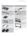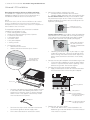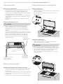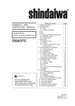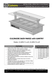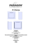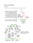
1
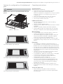
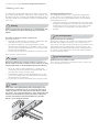
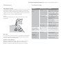
user manual al _dj[]hWj[ZXWhX[Yk[ k[ (EQBL100AS and EQBH100AS) AS) [b[Yjhebkn_dj[]hWj[ZXWhX[Yk[contents i Congratulations Congratulations and thank you for choosing our integrated barbecue. We are sure you will find your new barbecue a pleasure to use. Before you use the barbecue, we recommend that you read through the entire user manual, which provides the description of the barbecue and its functions. To avoid the risks that are always present when you use a gas appliance, it is important that it is installed correctly and that you read the safety instructions carefully to avoid misuse and hazards. We recommend that you keep this instruction booklet for future reference and pass it on to any future owners. After unpacking the barbecue please check it is not damaged. If in doubt, do not use the appliance but contact your local Electrolux Customer Care Centre. Contents FheZkYjZ[iYh_fj_ed FWhji ?cfehjWdjiW\[jo_dijhkYj_edi 7ii[cXb_d]j^[XWhX[Yk[ =Wiif[Y_ÓYWj_edi =WiYedd[Yj_edZ[jW_b DWjkhWb=Wi_dijWbbWj_ed Kd_l[hiWbBF=_dijWbbWj_ed =WiXejjb[iW\[jo_d\ehcWj_ed B[Waj[ijfheY[Zkh[ :_c[di_edi ?dijWbbWj_edmWhd_d]i ?dijWbbWj_ed_dijhkYj_edi =Wih[gk_h[c[dji I[jj_d]kfj^[XWhX[Yk[ <_jj_d]j^[ib_cb_d[b_ZehheWij_d]^eeZ Efj_edi\ehYedÓ]khWj_ede\^ejfbWj[iWdZ]h_bbi Ef[hWj_d]_dijhkYj_edi 9b[Wd_d]WdZYWh[ CW_dj[dWdY[ JhekXb[i^eej_d] MWhhWdjo __ ___ 1 2 3 3 3 4 + + , , , 8 8 8 / / 10 11 11 12 environmental tip Information on disposal for users såå-OSTåOFåTHEåPACKINGåMATERIALSåAREåRECYCLABLEå0LEASEå dispose of those materials through your local recycling depot or by placing them in appropriate collection containers. såå)FåYOUåWISHåTOåDISCARDåTHISåPRODUCTåPLEASEåCONTACTåYOURå local authorities and ask for the correct method of disposal. ii product description [b[Yjhebkn_dj[]hWj[ZXWhX[Yk[ Integrated barbecue with slimline lid 1 ' Slimline lid 2 2 Battery cover ) Gas connection point 3 4 + , 4 Burner controls + Grill assemblies x 2 sets , Hotplate - R emovable oil reservoir located at front of cooking surface (not illustrated) . F lame tamers x 2 located under grills (not illustrated) Integrated barbecue with roasting hood / / Roasting hood 10 Warming racks 10 '' Battery cover '( Gas connection point 11 ') Burner controls '* Grill assembly 12 '+ Hotplate 13 ', R emovable oil reservoir located at front of cooking surface (not illustrated) 14 '+ 14 '- F lame tamers x 2 located under grills (not illustrated) [b[Yjhebkn_dj[]hWj[ZXWhX[Yk[ parts iii Parts Contents of your barbecue pack: Z[iYh_fj_ed gjo Z[iYh_fj_ed gjo Burner box & trim surround 1 Natural gas regulator and braided hose 1 Rear heat shield 1 Universal LPG 1 regulator and braided hose Flame tamers 2 1 plastic bag containing this instruction book, labels, 4 ULPG injectors, allen key, ULPG adaptor, 2 fibre washers, natural gas installation pipe EITHER left Oil reservoirs (1 x left hand and 1 x right hand) 1 LH 1 RH Roasting hood assembly 1 Slimline lid assembly 1 right OR Solid hot plate 1 Grill assemblies 2 Tools you will need for assembly: såALLENåKEYåSUPPLIED electrolux integrated barbecue important safety instructions 1 Important safety instructions Please read the user manual carefully and store in a handy place for later reference. Meanings of the symbols used in this manual are shown below: For your safety please read this book before operating your barbecue. warning warning This symbol indicates information concerning your personal safety caution This symbol indicates information on how to avoid damaging the appliance This appliance MUST be installed and serviced only by a qualified licensed person. Improper installation, adjustment alteration or maintenance can cause injury or property damage. Please contact your nearest Electrolux Service Department for additional information or assistance for an approved installer. NOTE TO THE INSTALLER THIS MANUAL MUST REMAIN WITH THE OWNER FOR FUTURE REFERENCE tips and information warning This symbol indicates tips and information about use of the appliance environmental tip This symbol indicates tips and information about economical and ecological use of the appliance IF YOU SMELL GAS, do not attempt to light the barbecue. Locate the leak and re-tighten the leaking joint. Carry out the Leak Test procedure as described in this manual. If the leak persists, turn off the gas supply and call Electrolux Service or a Licensed Gas Fitter. warning Do not lean over barbecue when lighting. This symbol indicates never to do this Do not leave the barbecue unattended when alight. Do not delay lighting once the gas has been turned on. Do not store or use aerosol cans in the vicinity of the barbecue. Do not store flammable liquids in the vicinity of the barbecue. Do not use caustic or abrasive based cleaners on the barbecue. Do not operate the barbecue with the cover on. Do not attempt to dismantle or adjust the control valves. Do not attempt to dismantle or adjust the regulator. Do not test for leaks with a naked flame. Do not modify the construction of this appliance or modify the injector orifice size. Do not obstruct any ventilation of the barbecue. Do not allow children to operate or play near the barbecue. caution This barbecue is supplied set up for Natural Gas and is labelled accordingly. A Universal LPG conversion kit is included if required. Conversion of this unit to Universal LPG must be carried out by a qualified licensed person and a Certificate of Compliance must be issued to the owner on completion of the installation and conversion. 2 assembling electrolux integrated barbecue Assembling the barbecue 1. Remove all components from box. 2. Attach heat shield to rear of unit by inserting the three top tabs into the rear holes and sliding the shield down. 5. Place hotplate and grill sections into desired positions ensuring that the flame tamers are under grill sections NOTE ensure that grill assemblies are orientated correctly so that the surface of the grill is sloping forward to allow oil to drain into oil reservoirs. 3. Position flame tamers into desired locations (under where grill sections will be fitted) and fix back edge of the flame tamer into rear of barbecue body. assembled grill back front 6. After installation in bench, attach slimline lid or roasting hood as described in “Fitting the slimline lid or roasting hood” section of this manual. 4. Fit left and right hand oil reservoirs at front of barbecue. electrolux integrated barbecue gas specifications/natural gas installation 3 Gas specifications gas type Natural Gas installation natural gas universal LPG Maximum gas consumption 50 MJ/hr 50 MJ/hr Injector orifice diameter 1.75mm 0.95mm Number of injectors 4 4 Regulator pressure 1.00 kPa 2.75 kPa NOTES såå å4HISåAPPLIANCEå-534åBEåINSTALLEDåANDåSERVICEDåONLYåBYå a qualified licensed person. så å4HISåPRODUCTåISåINTENDEDåFORåOUTDOORåUSEåONLY så å4HISåPRODUCTåMUSTåBEåINSTALLEDåASåPERåTHEåINSTRUCTIONSå which requires the installation of venting to enable the barbecue to operate correctly. Failure to provide adequate ventilation for supply of air to the appliance may result in poor burner performance or excessive heat build-up within the mounting enclosure. så å6ENTILATIONåHOLESåINåTHEåUNITåMUSTåNOTåBEåOBSCUREDåBYå the installation. Preparing the unit for Natural Gas installation This barbecue is supplied set up for Natural Gas and is labelled accordingly. A Universal LPG conversion kit is included if required. Conversion of this unit to Universal LPG must be carried out by a qualified licensed person. A Certificate of Compliance must be issued to the owner on completion of the installation and conversion. Fit Natural Gas installation pipe to the barbecue gas inlet to enable access to the regulator in the installed position. When tightening the regulator or any other connection do not over-tighten. 1. Fitting the Natural Gas installation pipe å såå&ITåTHEåPIPEåENSURINGåTHEåBLUEåSEALINGåWASHERåISåINå place. Do not over-tighten. 2. Fitting the regulator å så & å ITåTHEåREGULATORåENSURINGåTHEåBLUEåSEALINGåWASHERå is in place and the arrow indicating gas flow is correct. Do not over-tighten. 3. Fit the hose å så ! å PPLYåTHREADåTAPEåORåSEALANTåTOåTHEåMALEåTHREADåONå the hose and screw into the regulator. Do not overtighten. Gas connection detail 137mm barbecue gas inlet 408mm sealing washer Natural Gas installation pipe sealing washer 46mm regulator – ensure arrow is pointing in the right direction hose with tapered thread – thread tape required 4. Fit to mains å så #ONNECTåTHEåBAYONETåENDåTOåMAINS Preparing the unit for Natural Gas connection to mains For Natural Gas connection a bayonet connection point should be installed by a licensed gas fitter prior to installing the barbecue unit. 4 universal LPG installation electrolux integrated barbecue Universal LPG installation Preparing the unit for Universal LPG installation. This barbecue is supplied set up for Natural Gas and is labelled accordingly. A Universal LPG conversion Kit is included to enable conversion to Universal LPG. NOTE #ONVERSIONåOFåTHISåUNITåTOå5NIVERSALå,0'åMUSTåBEåCARRIEDå out by a qualified licensed person and a Certificate of Compliance must be issued to the owner on completion of the installation and conversion. 2. Adjust the turndown setting on the valve å så å)FålTTEDåREMOVEåTHEåKNOBSåFROMåTHEåVALVES å så å2EMOVEåRUBBERåGROMMETSåFROMåCONTROLåPANELåHOLES For non flame failure valve adjust the turndown screw fully clockwise on each of the 4 valves using a small flat blade screwdriver. The valve is now set correctly for LPG operation (see diagram). turndown screw for non-flame failure valve The required components for conversion have been supplied. The components are: så (OSEåANDåREGULATORåASSEMBLY så å3MALLåPLASTICåBAGåCONTAININGååBRASSåINJECTORS så å5NIVERSALå,0'åSTICKER så åDATAåPLATEåLABEL så )NSTRUCTIONåSHEET så åTESTåPOINTåADAPTOR så åSEALINGåWASHER If flame failure fitted the turn down screw will need to be adjusted after unit is installed, and unit is ready for testing. This is done using a thin flat blade screw driver inserted through hole in centre of shaft spindle (see diagram). if flame failure valve fitted, turn down screw inside shaft with a small flat-blade screwdriver 1. Change the injectors å så å2EMOVEåTHEåFRONTåCOVER å så å2ELEASEåTHEåBURNERåRETAINERåCLIPåASåSHOWNå å remove spring clip by rotating over burner tube end så & å OLLOWINGåCONNECTIONåOFåGASåASåPERåSTEPSååLIGHTå all burners and one at a time set the burner to the lowest setting and check burner flame. Adjust turn down screw clockwise to achieve a small steady flame. 3. Connect the test point adaptor to the barbecue gas inlet å så & å ITåTHEåTESTåPOINTåADAPTORåENSURINGåTHEåBLUEåSEALINGå washer is in place and the arrow is pointing in the direction of gas flow. Do not over-tighten. 4. Connect the hose to the test point adaptor å så ! å PPLYåTHREADåTAPEåORåSEALANTåTOåTHEåMALEåTHREADåONå the hose and screw into the test point adaptor. front cover barbecue gas inlet å så å5NSCREWåANDåREPLACEåTHEååINJECTORåNIPPLESåLOCATEDå in the end of each tube feeding the burners. The Universal LPG injectors have a 0.95mm diameter orifice in them. They appear substantially smaller than the Natural Gas injectors. sealing washer test point adaptor – ensure arrow is pointing in the right direction LPG injector hose with tapered thread – thread tape required å så å så å2EFASTENåTHEåCLIPåTOåRETAINåTHEåTUBEåINåTHEåBURNERå Do not over tighten or distort supply tube. å&ITåTHEåFRONTåCOVERåBACKåONåANDåFASTENåSCREWS 5. Replace the ‘gas type’ sticker å så , å OCATEåTHEå@.ATURALå'ASåSTICKERåLOCATEDåONåTHEå barbecue gas inlet and remove it. Put the Universal LPG sticker in its place. electrolux integrated barbecue electronic display controls – electronic models 5 Gas bottle safety information Leak test procedure såå å4HISåAPPLIANCEåONCEåCONVERTEDåTOåUSEå5NIVERSALå,0'åISå designed to use a 9kg (20 lbs) gas cylinder. så å4HEåGASåCYLINDERåMUSTåBEåMADEåANDåMARKEDåINå accordance with specifications for LPG cylinders så å4HEåISOLATIONåVALVEåMUSTåBEåTURNEDåOFFåWHENåTHEå appliance is not in use. så å'ASåCYLINDERSåMUSTåBEåSTOREDåINåANåAPPROVEDåHOUSINGå out of reach of children. så å7HENåDISCONNECTINGåTHEåGASåBOTTLEåENSUREåTHATåALLåTHEå control valves are in the ‘OFF’ position. så å2EMOVEåTHEåBOTTLEåFROMåANYåHOUSINGåINåWHICHåITåMAYåBEå stored before disconnection. så å7HENåRECONNECTINGåTHEåHOSEåTOåTHEåBOTTLEåENSUREåTHATå all connections are tight before replacing in the storage compartment. så å#ARRYåOUTåAåLEAKAGEåCHECKåASåDETAILEDåBELOWåAFTERåEACHå reconnection. så % å NSUREåALLåGASåVALVESåAREåINåTHEå@/&&åPOSITION så å)NåAåSMALLåCONTAINERåMIXåAåSOLUTIONåOFåWATERåANDå detergent or soap. så å!FTERåCONNECTIONåOFåTHEåHOSEåTURNåONåTHEåVALVEåATåTHEå gas bottle or mains as appropriate. så å5SINGåAåBRUSHåAPPLYåTHEåSOLUTIONåTOåTHEåGASåCONNECTIONå points and look for bubbles forming. så "UBBLINGåWILLåINDICATEåAåLEAK så å4URNåOFFåTHEåVALVEåANDåRETIGHTENåTHEåJOINTå2EPEATåTHEå leak test. så å)FåTHEåLEAKåPERSISTSåTURNåOFåTHEåGASåATåTHEåISOLATIONåVALVESå and contact a licensed gas fitter to correct. Leak test points Check hose for signs of abrasions, cracks or leaks 6 installation warnings/installation instructions electrolux integrated barbecue Installation warnings Installation instructions warning så 4 å HISåAPPLIANCEåSHALLåONLYåBEåUSEDåINåANåABOVEåGROUNDå open air situation with natural ventilation without stagnant areas, where gas leakage and product of combustion are rapidly dispersed by wind or natural convection. This barbecue has been designed for outdoor use only. Refer to diagrams on right. så å.EVERåINSTALLåTHISåBARBECUEåINSIDEåANYåBUILDINGåGARAGEå shed or breezeway or inside a boat, caravan or recreational vehicle. This is to prevent the possibility of fire or carbon monoxide poisoning or asphyxiation. så å!NYåENCLOSUREåINåWHICHåTHISåAPPLIANCEåISåINSTALLEDåSHALLå comply with one of the following: – An enclosure with walls on all sides, but at least one permanent opening at the ground level and no overhead covering. – Within a partial enclosure that includes an overhead cover and no more than 2 walls. – Within a partial enclosure that includes an overhead cover and more than 2 walls, the following shall apply: – at least 25% of the total wall area is completely open and at least 30% of the remaining wall area is open and unrestricted så å)NåTHEåCASEåOFåBALCONIESåATåLEASTååOFåTHEåTOTALåOFå the side, back and front wall areas shall be and remain open and unrestricted. Outdoor area example 1 Outdoor area example 2 Choosing a location så å4HISåAPPLIANCEåMUSTåNOTåBEåINSTALLEDåONåANYåCOMBUSTIBLEå material. A minimum clearance from any combustible materials is 450mm (18”). så å4HEåVERTICALåCLEARANCEåABOVEåTHEåCOOKINGåSURFACEåTOåANYå combustible materials must be at least 600mm. så å4HISåAPPLIANCEåMUSTåBEåINSTALLEDåACCORDANCEåWITHå Australian Standards AS 4557 and AS 5601 and in accordance with local authority. så å7HENåUSINGå,0'åINåANåENCLOSUREåVENTILATIONåMUSTåBEå provided. Gas is highly explosive and can cause serious injury and damage to property if allowed to accumulate and then be ignited. så å4HISåBARBECUEåISåINTENDEDåTOåBEåBUILTåINTOåAåBENCHåTOPå with a minimum depth of 600 mm. så å!VOIDåWINDYåPOSITIONSåASåTHISåWILLåAFFECTåCOOKINGå performance and burner efficiency. If this situation cannot be avoided some shielding may be necessary. The mounting enclosure så å4HEåBARBECUEåREQUIRESåAåNONCOMBUSTIBLEåBARRIERåUNDERå the barbecue to prevent excessive temperatures being accessed. The barrier panel is to be placed 30mm under the base of unit. There are spacers added to bottom of unit to prevent barrier panel being too close to barbecue base. Refer to diagram on next page. så å4HEåMOUNTINGåENCLOSUREåMUSTåBEåCONSTRUCTEDåFROMå non-combustible materials. Suitable materials for construction include masonry, granite, marble, Hardiplank® , Villaboard® over a metal frame or tiles. så å4HISåAPPLIANCEåREQUIRESåVENTINGåINåTHEåFRONTåWALLåOFåTHEå enclosure. See diagram below for details. så å4HISåAPPLIANCEåCANåBEåMOUNTEDåEITHERåINåANåISLANDåTYPEå bench or a bench with a splashback. Please read the specific requirements for each mounting situation. Island style installation så å)FåTHISåAPPLIANCEåISåINSTALLEDåINåANåISLANDåMOUNTåITåCANåBEå centrally positioned. Special attention should be given to the overall size of the island top to consider the hood open and the overhang. Please see below. så å4HEåCUTOUTåSIZEåREQUIREDåISåMMåXåMMåSEEå diagram). Outdoor area example 3 both ends open warning Outdoor area example 4 open side at least 25% of total wall area 30% or more in total of the remaining wall area is open and unrestricted Outdoor area example 5 open side at least 25% of total wall area 30% or more in total of the remaining wall area is open and unrestricted så 4 å HISåAPPLIANCEåREQUIRESåVENTINGå!NåOPENåAREAåASå indicated below must be allowed for. A suitable grille can be fitted if desired. This vent area is to allow air into the enclosure for the correct combustion of gases and for the correct exhausting of the products of combustion. In the case of LPG the gas is heavier than air, this vent in the situation where there may be a leak allows the gas to escape from the enclosure. This vent must be 700mm x 25mm minimum and positioned centrally 135mm below the mounting surface. (see diagram). Installing in a bench with a splashback så å4HEåSPLASHBACKåMUSTåBEåMADEåFROMåAåNONCOMBUSTIBLEå material. så å)NåTHEåCASEåOFåMOUNTINGåTHISåAPPLIANCEåAGAINSTåAåWALLå or fence it is imperative that care be taken to ensure the isolation of combustible materials. All combustible materials must be kept 450mm away from the barbecue. electrolux integrated barbecue installation instructions 7 så å4HEåMINIMUMåWIDTHåOFåTHEåMOUNTINGåSURFACEåISåMM så å4HEåCUTOUTåSIZEåREQUIREDåISåMMåXåMMåSEEå diagram). så å&ORåROASTINGåHOODåMODELSåTHEREåISåAåSPECIlCåCLEARANCEå required at the back of the barbecue between the splashback and the bench cut-out of 73mm minimum. This is to allow clearance for the hood to open. warning så 4 å HISåAPPLIANCEåREQUIRESåVENTINGå!NåOPENåAREAåASå indicated below must be allowed for. A suitable grille can be fitted if desired. This vent area is to allow air into the enclosure for the correct combustion of gases and for the correct exhausting of the products of combustion. In the case of LPG the gas is heavier than air, this vent in the situation where there may be a leak allows the gas to escape from the enclosure. This vent must be 700mm x 25mm minimum and positioned centrally 135mm below the mounting surface. (see diagram). wall 589mm 562mm wall 538mm 453mm 601mm bench width 600mm min. 211mm 553mm 42mm bench bench bench bench 56mm 177mm 177mm 25mm 73mm min. from cut-out 25mm 73mm min. from cut-out 464mm 464mm minimum clearance to back wall minimum clearance to back wall 925mm 943mm 553mm 526mm 538mm 538mm 1058mm 1058mm splashback 600mm min. 135mm 600mm min. 1025mm cut-out 135mm 1025mm x 502 cut-out 502mm cut-out 25mm 700mm Island style installation (example shown with barbecue with slimline line) 1025mm cut-out 1025mm x 502 cut-out 502mm cut-out 25mm 700mm Installation in a bench with splashback (example shown with barbecue with roasting hood) 8 gas requirements/setting up the barbecue/fitting the lid or hood electrolux integrated barbecue Gas requirements Fitting the slimline lid or roasting hood Natural Gas requirements såå å4HEåENCLOSUREåMUSTåBEåCONSTRUCTEDåSOåTHATåACCESSåCANå be gained to the Natural Gas regulator at all times. så å&ORå.ATURALå'ASåTHEåGASåSUPPLYåISåREQUIREDåTOåBEå connected to 1.2m flexible hose supplied and therefore must be located within this distance så å4HEåmEXIBLEåHOSEåHASåAåQUICKåCONNECTåGASåCOUPLINGå4HEå corresponding mating fitting will be required at the gas supply end. så å&ORåPIPEåSIZINGåREQUIREMENTSåFORåSUPPLYåPIPEåREFERåTOå AS5601. Fitting of slimline lid så å5NPACKåTHEåSLIMLINEåLID så å2EMOVEåSIDEåSCREWSåFROMåBARBECUEåTRIMåSURROUNDåUSINGå allen key supplied. så å&ITåBRACKETSåTOåTRIMåSURROUNDåWITHåTHEåSAMEåSCREWS så &ITåLIDåTOåBRACKETS Universal LPG Requirements warning så )åFåANå,0'åBOTTLEåISåTOåBEåSTOREDåINåTHEåENCLOSUREå under the barbecue unit, it must be isolated from the barbecue unit with a non-combustible panel. The enclosure must comply with the requirements of AS5601. så å!3åVENTILATIONåREQUIREMENTSåFORåCYLINDERåSTORAGEåAREå Where of sheet metal or similar impervious construction there shall be ventilation openings at the top and bottom of the enclosure or recess, each opening providing a free area of at least 200cm2 for every cylinder enclosed. cut hole in noncombustible barrier for hose only Fitting of roasting hood så 5NPACKåTHEåROASTINGåHOOD så å2EMOVEåSIDEåANDåREARåSCREWSåFROMåBARBECUEåTRIMå surround using allen key supplied. important 210mm så $ å UEåTOåTHEåSIZEåOFåTHEåROASTINGåHOODåITåISåRECOMMENDEDå that two people place the roasting hood into position. så å7HENålTTINGåROASTINGåHOODåASSEMBLYåTAKEåPARTICULARå care to avoid scratching of the external trim. så å/NCEåINåPOSITIONålXåHOODåASSEMBLYåTOåTRIMåSURROUNDå with same screws. front of enclosure removed for clarity at least 30mm clearance between bottom of barbecue and barrier non-combustible barrier required under barbecue Setting up the barbecue Setting up the barbecue in mounting enclosure så å!FTERåTHEåENCLOSUREåHASåBEENåCONSTRUCTEDåASåDESCRIBEDå on page 6, position the assembled barbecue into the cut-out hole. så å#HECKåTHATåTHEåBARBECUEåISåLEVELåANDåISålRMLYåSUPPORTED så å#ONNECTåTOåGASåSUPPLYå5NIVERSALå,0'åORå.ATURALå'ASå and leak test. så å&ORålTMENTåOFåTHEåSLIMLINEåLIDåORåROASTINGåHOODåSEEåRIGHT electrolux integrated barbecue configuration of hotplates and grills/operating instructions 9 Options for configuration of hotplates and grills important Ensure flame tamers are positioned under the grill panels grill panels flame tamers Operating instructions Control functions "EFOREåLIGHTINGåTHEåBARBECUE så å#HECKåTHATåALLåHOSESåANDåGASålTTINGSåAREåTIGHT så å/PENåTHEåSLIMLINEåLIDåORåTHEåROASTINGåHOOD NOTE The slimline lid is designed as a cover for weather protection. The lid is not designed to be used as a cooking hood. så å#HECKåALLåCONTROLåKNOBSåAREåINåTHEå@/&&åPOSITION så å%NSUREåTHATåTHEåCOOKINGåSURFACESåAREåCLEAN så 4URNåTHEåGASåISOLATIONåVALVEå@/. Lighting instructions så å$OåNOTåATTEMPTåTOåLIGHTåBURNERSåWITHåTHEåCOOKINGå surfaces covered. så å2EADåINSTRUCTIONSåBEFOREåLIGHTING så å4OåLIGHTåAåBURNERåDEPRESSåTHEåKNOBåANDåROTATEåTOå@2!0)$å PREHEAT’. så ( å OLDåFORååSECONDSåRELEASEåANDåCHECKåTHEåmAME så )åFåBURNERåDIDåNOTåLIGHTåTURNåKNOBåTOåTHEå@/&&åPOSITIONå Allow gas to disperse, then repeat lighting procedure. Manual lighting så )åFåINåTHEåADVENTåOFåTHEåAUTOMATICåIGNITIONåSYSTEMåNOTå working, the barbecue can be lit manually. så , å IFTåTHEåFRONTåEDGEåOFåTHEåHOTPLATEåANDåGRILLSåROTATEåTHEå knob to the ‘RAPID PREHEAT’ and place a lighted match near to the burner intended to be lit. så / å NCEåALIGHTåREPEATåFORåOTHERåBURNERSå,OWERåTHEåGRILLSå and hotplate, taking extreme care with hot surfaces and flames. Left hand hotplate, right hand grill Left hand half grill, central hotplate, right hand half grill Left hand grill, right hand hotplate Preheating så 4 å HISåBARBECUEåISålTTEDåWITHåHIGHåPOWERåBURNERSå)Nå most conditions it will only be necessary to preheat the barbecue for 5 minutes before cooking can commence. så ! å SåWITHåMOSTåTHINGSåEXPERIENCEåWILLåFAMILIARISEåYOUåWITHå the effectiveness of and the time required to achieve the desired preheating time to obtain the desired cooking temperature. så 4 å ESTINGåHASåSHOWNåTHATåTHEåBURNERSåCANåBEåTURNEDåTOå the low position for satisfactory cooking. så )åFåTHEåBARBECUEåISålTTEDåWITHåAåSLIMLINEåLIDåITåISåADVISABLEå to remove the slimline lid in windy conditions. såå )åFåTHEåUNITåDOESåNOTåOPERATEåCORRECTLYåREFERåTOåTHEå troubleshooting section on page 11. så )åFåTHEåBURNERSåAREåLEFTåTOåRUNåTOOåHOTåTHEREåWILLåBEå excessive smoking during the cooking process and subsequent burning of the food being prepared. This may also result in excessive flaring of the fat being emitted from the food. så 2 å OASTINGåWITHåTHEåHOODåCLOSEDåONLYåREQUIRESåTHEåå outermost burners to be on low setting for satisfactory cooking. To turn the burner off så 7 å HENåCOOKINGåISåCOMPLETEåROTATEåTHEåKNOBåFULLYå clockwise so the pointer on the knob is positioned at the off position. 10 cleaning and care electrolux integrated barbecue Cleaning and care The Electrolux Integrated barbecue has been constructed from select grade stainless steel which, if not cared for, may discolour over time. To keep your barbecue looking its best we recommend that the cooking surfaces are cleaned after every use. warning Please ensure that your barbecue is switched off and has cooled down before following the instructions below. Cleaning the Oil Reservoirs The Integrated barbecue has a unique oil management system which uses overlapping channels to drain all oil to the front into easily removed reservoirs and should be cleaned after each use. så å4OåREMOVEåRESERVOIRSåPULLåUPWARDSåFROMåTHEåFRONTåOFåTHEå barbecue and dispose of the contents of the catchment responsibly. Rinse oil reservoirs in warm soapy water. The reservoirs can be placed in the dishwasher if desired. tips and information Cleaning of Stainless Steel components Hot Plate and Grill så å2EMOVEåALLåSOLIDåMATERIALSåANDåEXCESSåGREASEåFROMåGRILLå and hotplate using scraper or wire brush så å4OåMAKEåCLEANINGåEASYåTHEåTWOåGRILLåHALVESåCANåBEå removed with the hotplate. For stubborn stains, simply soak the grill and plate components in hot soapy water before rinsing thoroughly så å%NSUREåTHATåALLåSURFACESåAREåDRIEDåWITHåAåCLEANåDRYåCLOTH Special note on “tea staining” Sometimes stainless steel surfaces are affected by a brown discolouration called tea staining. This usually occurs in areas which use high heat and can be easily removed using specialised stainless steel cleaners. For best results, we recommend that specialised cleaners be used regularly on all stainless steel components. You will find these cleaners at most hardware stores. Other stainless steel surfaces tips and information caution Do not use abrasive or caustic cleaners, scourers or metal scrapers on these stainless steel surfaces as they may permanently scratch and damage your barbecue. så 7 å ASHåALLåSTAINLESSåSTEELåCOMPONENTSåINCLUDINGåTHEå slimline lid, the roasting hood and control knobs with a soft dishcloth using hot soapy water så å4HEåBARBECUEåINTERIORåCANåBEåWIPEDåDOWNåWITHåAåSOFTå cloth in hot soapy water. The rear panel of the interior is removable for easy cleaning så å%NSUREåTHATåALLåSURFACESåAREåDRIEDåWITHåAåCLEANåDRYåCLOTH caution Take extra care (particularly when cleaning on and around the control knobs) to ensure that water and soapy residue do not enter the control panel, where the valves are or into the burners. Care should also be taken not to disturb the spark electrode. A distance of 5mm should be maintained between it and the burners (see diagram below). 5mm Special note on stainless steel The stainless steel panels may distort while in use but will return to normal when cold. electrolux integrated barbecue maintenance/troubleshooting 11 Maintenance The ignition system To change the battery unscrew the cover. Lift out the spring and battery. Replace with a new AA battery and replace the cover. Do not over-tighten the screw cover as this may distort the trim panel. Test by depressing the knob and an audible ‘clicking’ sound should be heard. Troubleshooting problem possible cause remedy "ARBECUEåWONTå light No gas Check isolation valve is ON Gas bottle empty – refill or change gas bottle Ignition system not working NOTE Ensure that the battery has been placed in the correct orientation. Check battery – should hear a clicking noise when the knob is depressed Replace battery Manually light the barbecue Air vents The mounting enclosure air vents should be checked prior to each use, to ensure they are clear of any obstructions that may affect the free flow of air. Stainless steel burners "URNERSåSHOULDåBEåCHECKEDåATåLEASTåONCEåPERåYEARåANDå cleaned as necessary. Inspect burners to ensure no residues have been deposited and gas ports are clear. Ignition electrode wet or dirty Gently clean and dry electrode ensuring position is correct Excess smoke being emitted from the cooking area Gas valve set too high Turn gas valves down or turn off selected burners Smell of gas Gas leak Turn off gas at the isolation valves DO NOT ATTEMPT TO LIGHT THE APPLIANCE Check for leaks, tighten joints If problem persists call Electrolux Service 12 warranty electrolux integrated barbecue Warranty FOR SALES IN AUSTRALIA AND NEW ZEALAND !00,)!.#%å%,%#42/,58å).4%'2!4%$å"!2"%#5% This document sets out the terms and conditions of product warranties for Electrolux branded appliances. It is an important document. Please keep it with your proof of purchase documents in a safe place for future reference should you require service for your Electrolux appliance. General Terms and Conditions 1. In this warranty å Aå å@%LECTROLUXåMEANSå%LECTROLUXå(OMEå0RODUCTSå0TYå,TDå!".åå 004 762 341 in respect of Appliances purchased in Australia and Electrolux (NZ) Limited in respect of Appliances purchased in New Zealand; (b) ‘Appliance’ means any Electrolux product purchased by you accompanied by this document; (c) ‘Warranty Period’ means (i) where you use the Appliance for personal, domestic or household purposes in Australia the period of ‘24’ months and in New Zealand the period of ‘24’ months; (ii) where you use the Appliance for commercial purposes, in Australia the period of ‘3’ months and in New Zealand the period of ‘3’ months, (if the period stated is 0 months you are not covered by this product warranty) following the date of original purchase of the Appliance; (d) ‘you’ means the purchaser of the Appliance not having purchased the appliance for re-sale, and ‘your’ has a corresponding meaning. 2. This warranty only applies to Appliances purchased and used in Australia or New Zealand and is in addition to (and does not exclude, restrict, or modify in any way) any non-excludable statutory warranties in Australia or New Zealand. 3. Electrolux warrants that, when dispatched from an Electrolux warehouse, the Appliance is free from defects in materials and workmanship for the Warranty Period. 4. During the Warranty Period Electrolux or its Authorised Service Centre will, at no extra charge if your appliance is readily accessible without special equipment, and subject to these terms and conditions, repair or replace any parts which it considers to be defective. Electrolux or its ASC may use reconditioned parts to repair your appliance. You agree that any replaced Appliances or parts become the property of Electrolux. This warranty does not apply to light globes, batteries, filters or similar perishable parts. 5. Parts and Appliances not supplied by Electrolux are not covered by this warranty. 6. Where you are within an Electrolux service area, this warranty covers the cost of transport of the Appliance to and from Authorised Service Centres of Electrolux and travelling costs for representatives of the Authorised Service Centre to and from your home or business. If you are outside an Electrolux service area, you will bear these costs. For information about whether you are within an Electrolux service area, please phone 13 13 49 in Australia, or 0800 10 66 10 in New Zealand. 7. Proof of purchase is required before you can make a claim under this warranty. 8. You may not make a claim under this warranty unless the defect claimed is due to faulty or defective parts or workmanship. Electrolux is not liable in the following situations (which are not exhaustive): (a) The Appliance is damaged by: (i) accident (ii) misuse or abuse, including failure to properly maintain or service (iii)normal wear and tear (iv) power surges, electrical storm damage or incorrect power supply (v) incomplete or improper installation (vi) incorrect, improper or inappropriate operation (vii) insect or vermin infestation. (b) The Appliance is modified without authority from Electrolux in writing. (c) The Appliance’s serial number or warranty seal has been removed or defaced. (d) The Appliance was serviced or repaired by anyone other than Electrolux or its Authorised Service Centres. 9. This warranty, the contract to which it relates and the relationship between you and Electrolux are governed by the law applicable in the Australian State where the Appliance was purchased or the law applicable in New Zealand if the Appliance was purchased in New Zealand. Where the Appliance was purchased in New Zealand for business purposes the Consumer Guarantee Act does not apply. Limitation of Liability 10.To the extent permitted by law: (a) Electrolux excludes all warranties other than as contained in this document; (b) Electrolux shall not be liable for any loss or damage whether direct or indirect or consequential arising from your purchase, use or nonuse of the Appliance. 11.Provisions of the Trade Practices Act and State consumer legislation in Australia, and the Consumer Guarantees Act, the Sale of Goods Act and the Fair Trading Act in New Zealand, imply warranties or conditions, or impose obligations, upon Electrolux which cannot be excluded, restricted or modified. To the extent permitted by law, the liability of Electrolux (if any) arising out of or in relation to the Appliance or any services supplied by Electrolux shall be limited (where it is fair and reasonable to do so),: (a) in the case of Appliances, at its option, to the replacement or repair of the Appliances or the supply of equivalent products or the payment of the cost of replacing the Appliances or having the Appliances repaired or of acquiring equivalent Appliances. Upon being replaced, parts and Appliances become the property of Electrolux; or (b) in the case of services, at its option, to the supply of the services again or the payment of the cost of having the services re-supplied; and in the case of Appliances or services supplied in New Zealand, loss or damage whether direct or indirect or consequential that is reasonably foreseeable. Privacy You acknowledge that in the event that you make a warranty claim it will be necessary for Electrolux and its Authorised Service Centres to exchange information in relation to you to enable Electrolux to meet its obligations under this warranty. Important Notice "EFOREå#ALLINGåAå3ERVICEå4ECHNICIANåPLEASEåCHECKåCAREFULLYåTHEåOPERATINGåINSTRUCTIONSåSERVICEåBOOKLETåANDåTHEåWARRANTYåTERMSåANDåCONDITIONS FOR SERVICE or to find the address of your nearest state service centre in Australia PLEASE CALL 13 13 49 For the cost of a local call (Australia only) FOR SERVICE or to find the address of your nearest authorised service centre in New Zealand FREE CALL 0800 10 66 10 (New Zealand only) SERVICE AUSTRALIA ELECTROLUX HOME PRODUCTS www.electrolux.com.au SERVICE NEW ZEALAND ELECTROLUX HOME PRODUCTS www.electrolux.co.nz FOR SPARE PARTS or to find the address of your nearest state spare parts centre in Australia PLEASE CALL 13 13 50 For the cost of a local call (Australia only) FOR SPARE PARTS or to find the address of your nearest state spare parts centre in New Zealand FREE CALL 0800 10 66 20 (New Zealand only) ;b[Yjhebkn>ec[FheZkYji7kijhWb_W telephone: 1300 363 640 fax: 1800 350 067 email: [email protected] web: www.electrolux.com.au J^[J^ek]^j\kb:[i_]d?ddelWjeh$ Do you remember the last time you opened a gift that made you say “Oh! How did you know? That’s exactly what I wanted!” That’s the kind of feeling that the designers at Electrolux seek to evoke in everyone who chooses or uses one of our products. We devote time, knowledge, and a great deal of thought to anticipating and creating the kind of appliances that our customers really need and want. This kind of thoughtful care means innovating with insight. Not design for design’s sake, but design for the user’s sake. For us, thoughtful design means making appliances easier to use and tasks more enjoyable to perform, freeing our customers to experience that ultimate 21st century luxury, ease of mind. Our aim is to make this ease of mind more available to more people in more parts of their everyday lives, all over the world. So when we say we’re thinking of you, you know we mean just that. ;b[Yjhebkn$J^_da_d]e\oek$ Share more of our thinking at www.electrolux.com.au F%De$&,',&&'/)© Copyright 2007 Electrolux Home Products Pty Ltd ABN 51 004 762 341 Print code: EINTBBQUM_Dec 07