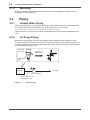
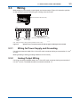
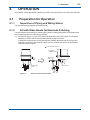
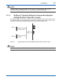
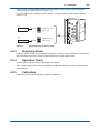
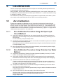
1
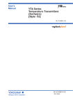
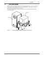
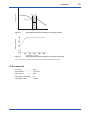
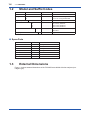
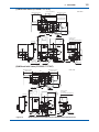
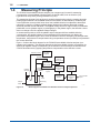
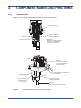
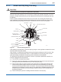
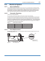
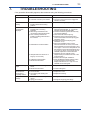
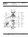
User’s Manual Model FC500G Free Available Chlorine Analyzer (Non-Reagent Type) IM 12F5A2-01E IM 12F5A2-01E 4th Edition i Introduction This user’s manual describes the specifications, installation, operation, maintenance, and troubleshooting for Model FC500G Free Available Chlorine Analyzer. Read this manual thoroughly to understand the contents before operating the equipment. Notes on Hardware Appearance and Accessories Check the following when you receive the product: • Appearance • Standard accessories Contact our sales representative or your local distributor if the product’s coating has come off, it has been damaged, or there is shortage of required accessories. Model and Suffix Codes The name plate on the product contains the model and suffix codes. Compare them with those in the general specification to make sure the product is the correct one. If you have any questions, contact our sales representative or your local distributor. Media No. IM 12F5A2-01E 4th Edition : Aug. 2012 (YK) All Rights Reserved Copyright © 2007, Yokogawa Electric Corporation IM 12F5A2-01E ii For the safe use of this equipment Safety, Protection, and Modification of the Product • In order to protect the system controlled by the product and the product itself and ensure safe operation, observe the safety precautions described in this user’s manual. We assume no liability for safety if users fail to observe these instructions when operating the product. • If this instrument is used in a manner not specified in this user’s manual, the protection provided by this instrument may be impaired. • Be sure to use the spare parts approved by Yokogawa Electric Corporation (hereafter simply referred to as YOKOGAWA) when replacing parts or consumables. • Modification of the product is strictly prohibited. • The following symbols are used in the product and user’s manual to indicate that there are precautions for safety: Notes on Handling User’s Manuals • Please hand over the user’s manuals to your end users so that they can keep the user’s manuals on hand for convenient reference. • Please read the information thoroughly before using the product. • The purpose of these user’s manuals is not to warrant that the product is well suited to any particular purpose but rather to describe the functional details of the product. • No part of the user’s manuals may be transferred or reproduced without prior written consent from YOKOGAWA. • YOKOGAWA reserves the right to make improvements in the user’s manuals and product at any time, without notice or obligation. • If you have any questions, or you find mistakes or omissions in the user’s manuals, please contact our sales representative or your local distributor. Warning and Disclaimer The product is provided on an “as is” basis. YOKOGAWA shall have neither liability nor responsibility to any person or entity with respect to any direct or indirect loss or damage arising from using the product or any defect of the product that YOKOGAWA can not predict in advance. IM 12F5A2-01E iii Symbol Marks Throughout this user’s manual, you will find several different types of symbols are used to identify different sections of text. This section describes these icons. WARNING Indicates a potentially hazardous situation which, if not avoided, could result in death or serious injury. CAUTION Indicates a potentially hazardous situation which, if not avoided, may result in minor or moderate injury. It may also be used to alert against unsafe practices. IMPORTANT Indicates that operating the hardware or software in this manner may damage it or lead to system failure. NOTE Draws attention to information essential for understanding the operation and features. IM 12F5A2-01E iv After-sales Warranty Do not modify the product. During the warranty period, for repair under warranty consult the local sales representative or service office. Yokogawa will replace or repair any damaged parts. Before consulting for repair under warranty, provide us with the model name and serial number and a description of the problem. Any diagrams or data explaining the problem would also be appreciated. If we replace the product with a new one, we won’t provide you with a repair report. Yokogawa warrants the product for the period stated in the pre-purchase quotation Yokogawa shall conduct defined warranty service based on its standard. When the customer site is located outside of the service area, a fee for dispatching the maintenance engineer will be charged to the customer. In the following cases, customer will be charged repair fee regardless of war- ranty period. • Failure of components which are out of scope of warranty stated in instruction manual. • Failure caused by usage of software, hardware or auxiliary equipment, which Yokogawa Electric did not supply. • Failure due to improper or insufficient maintenance by user. • Failure due to modification, misuse or outside-of-specifications operation which Yokogawa does not authorize. • Failure due to power supply (voltage, frequency) being outside specifications or abnormal. • Failure caused by any usage out of scope of recommended usage. • Any damage from fire, earthquake, storms and floods, lightning, disturbances, riots, warfare, radiation and other natural changes. Yokogawa does not warrant conformance with the specific application at the user site. Yokogawa will not bear direct/indirect responsibility for damage due to a specific application. Yokogawa Electric will not bear responsibility when the user configures the product into systems or resells the product. Maintenance service and supplying repair parts will be covered for five years after the production ends. For repair for this product, please contact the nearest sales office described in this instruction manual. IM 12F5A2-01E Toc-1 Model FC500G Free Available Chlorine Analyzer (Non-Reagent Type) IM 12F5A2-01E 4th Edition CONTENTS Introduction ..........................................................................................................i For the safe use of this equipment ...................................................................ii After-sales Warranty ..........................................................................................iv 1. 2. 3. OVERVIEW ................................................................................................ 1-1 1.1 Standard Specifications ................................................................................... 1-2 1.2 Model and Suffix Codes ................................................................................... 1-4 1.3 External Dimensions ........................................................................................ 1-4 1.4 Measuring Principle .......................................................................................... 1-6 COMPONENT NAMES AND FUNCTIONS........................................................ 2-1 2.1 Detector .............................................................................................................. 2-1 2.2 Converter ........................................................................................................... 2-2 INSTALLATION, PIPING, AND WIRING ....................................................3-1 3.1 3.2 3.3 4. Installation ......................................................................................................... 3-1 3.1.1 Location.............................................................................................. 3-1 3.1.2 Mounting ............................................................................................ 3-2 Piping ................................................................................................................. 3-2 3.2.1 Sample Water Piping ......................................................................... 3-2 3.2.2 Air Purge Piping ................................................................................. 3-2 Wiring ................................................................................................................. 3-3 3.3.1 Wiring for Power Supply and Grounding ........................................... 3-3 3.3.2 Analog Output Wiring ......................................................................... 3-3 OPERATION .............................................................................................. 4-1 4.1 4.2 Preparation for Operation ................................................................................ 4-1 4.1.1 Inspection of Piping and Wiring Status .............................................. 4-1 4.1.2 Fill with Glass Beads for Electrode Polishing .................................... 4-1 4.1.3 Measuring Range Setting .................................................................. 4-2 4.1.4 Setting of “Applied Voltage Compensation/Applied Voltage Fixation’’ Selection Jumper ............................................................................... 4-3 Start-Up .............................................................................................................. 4-4 4.2.1 Supplying Sample Water ................................................................... 4-4 4.2.2 Confirmation of “Power Supply Voltage” and “Measuring Range” Selection Jumpers Setting Status...................................................... 4-4 4.2.3 Supplying Power ................................................................................ 4-5 4.2.4 Operation Check ................................................................................ 4-5 IM 12F5A2-01E Toc-2 4.2.5 4.3 5. Steady State Operation .................................................................................... 4-6 CALIBRATION ........................................................................................... 5-1 5.1 5.2 6. Calibration .......................................................................................... 4-5 Zero Calibration................................................................................................. 5-1 5.1.1 Zero Calibration Procedure Using the Open Input Circuit Method .... 5-1 5.1.2 Zero Calibration Procedure Using Chlorine-Free Water Method ...... 5-1 Span Calibration ............................................................................................... 5-2 5.2.1 Span Calibration Procedure Using the Sampling Method................. 5-2 5.2.2 Span Calibration Procedure Using Standard Solution Method ......... 5-2 INSPECTION AND MAINTENANCE ........................................................ 6-1 6.1 6.2 Mechanical System........................................................................................... 6-1 6.1.1 Indicator Electrode Polishing ............................................................. 6-1 6.1.2 Glass Beads and Measuring Tank Cleaning ..................................... 6-2 6.1.3 Brush and Slip Ring Checking ........................................................... 6-3 Electrical System .............................................................................................. 6-5 6.2.1 Span Calibration ................................................................................ 6-5 6.2.2 Converter Checking ........................................................................... 6-5 6.2.3 Fuse Replacement............................................................................. 6-5 7. TROUBLESHOOTING .............................................................................. 7-1 8. AUXILIARIES AND CONSUMABLES ...................................................... 8-1 8.1 Auxiliaries and Consumables List .................................................................. 8-1 8.2 Auxiliaries and Consumables ......................................................................... 8-1 8.2.1 Polisher (Part number: K9088PE) ..................................................... 8-1 8.2.2 Glass Beads (Part number: K9332ZJ)............................................... 8-1 8.2.3 Indicator Electrode (Part number: K9332MB) ................................... 8-1 8.2.4 Grease (Part number: K9044FX)....................................................... 8-1 8.2.5 Counter Electrode (Part number: K9332MK) .................................... 8-1 8.2.6 Brush and Slip Ring (Part number: K9332JX, K9332JZ) .................. 8-2 Customer Maintenance Parts List ...................................... CMPL 12F05A02-01E Revision Information ...............................................................................................i IM 12F5A2-01E 1-1 <1. OVERVIEW> 1. OVERVIEW Model FC500G Free Available Chlorine Analyzer (Non-Reagent Type) is used for continuous measurement of free available chlorine in tap water distribution. This analyzer consists of a detector and a converter as shown in Figure 1.1. This chapter describes the FC500G free available chlorine analyzer specifications and its measuring principle. Detector Converter Figure 1.1 Appearance of Model FC500G Free Available Chlorine Analyzer IM 12F5A2-01E 1-2 <1. OVERVIEW> 1.1 Standard Specifications Measured Object: Free available chlorine contained in tap water Measuring System: Polarographic method using rotating electrode Measuring Ranges: 0 to 1 / 0 to 2 / 0 to 3 mg/l (Model FC500G-1) 0 to 5 / 0 to 10 mg/l (Model FC500G-5) (Air purge is necessary.) Indication: Digital (3 1/2 LCD) Output Signal: 4 to 20 mA DC (Load resistance: Maximum 500 Ω) Operating pH Range of Sample Solution: pH 6.5 to 7.5: For measured liquids whose pH exceeds the above limits, error increases (refer to the following figure). Sample Solution: Temperature: 0 to 40 °C (temperature compensation range 5 to 35 °C). Pressure: 1 to 30 kPa (for without VALVE) 1 to 150 kPa (with VALVE) Flow Rate: 0.1 to 2.5 l/min (at tank inlet) Conductivity: 100 to 300 μS/cm SS (Suspended Solid): 10 mg/l or less Air Purging (for only 0 to 5 / 0 to 10 mg/l Range) Supply Air Pressure: About 50 to 140 kPa Air Consumption: About 5 l/min Electrode: Indicator Electrode: Rotating gold electrode Counter Electrode: Silver electrode (with Pt 1000 installed) Electrode Cleaning: Glass beads used for cleaning Wetted Part Materials: Measuring Tank: Acrylic resin (molding) Piping: Flexible PVC and PE Color: Muncell 5Y7/1 Finish: Baked polyurethane resin coating Mounting: On the wall or 2 inch pipe (OD 60.5 mm) Ambient Temperature: -5 to 50 °C Power Supply: 100 or 110 V AC; or 200 or 220 V AC as per order ±10 %, 50 or 60 Hz Power Consumption: Approximately 15 VA (100 or 110 V), 20 VA (200 or 220 V) Weight: Approximately 6.5 kg Characteristics: Reproducibility: 2 % of full scale Linearity: ±5 % of full scale Stability: Zero Drift: Within ±1 % of full scale/month Span Drift: Maximum -10 % of full scale/month Response Time: Approximately 2 minutes (time required to obtain a value within 90 % of final value) Ambient Temperature Influence: ±0.5 % of full scale/10 °C Power Voltage Fluctuation Influence: ±0.5 % of full scale/10 % of rated voltage Sample Solution Temperature Compensation Error: ±3 % of full scale/5 to 35 °C IM 12F5A2-01E <1. OVERVIEW> 1-3 Indicated value (mg/l) 1.0 pH6.5 0.5 0 pH7.5 Operating range 3 4 5 6 7 8 9 10 pH Figure 1.2 Sensitivity characteristics of diffusion current by pH value Figure 1.3 Sensitivity characteristics of diffusion current by conductivity Note: If conductivity exceeds 300 μS/cm, default value of applied voltage should be changed. nAccessories Fuse (1 A) .........................4 pcs. Glass Beads .....................1 (2 bags) Allen Wrench ....................2 pcs. Screwdriver (flat blade) ...1 pc. Polishing Powder ..............1 bottle IM 12F5A2-01E 1-4 <1. OVERVIEW> 1.2 Model and Suffix Codes Model Option Code Suffix Code Description FC500G ���������������������������������� ���������������������� Free Available Chlorine Analyzer Range -1 -5 Output signal Power ���������������������� 0 to 1 / 0 to 2 / 0 to 3 mg/l Switchable ���������������������� 0 to 5 / 0 to 10 mg/l Switchable 1 ���������������������� 4 to 20 mA DC 3 4 5 6 Inlet valve ���������������������� ���������������������� ���������������������� ���������������������� ���������������������� Without Valve ���������������������� With Valve 0 1 Language 100 V ±10%, 50/60 Hz 110 V ±10%, 50/60 Hz 200 V ±10%, 50/60 Hz 220 V ±10%, 50/60 Hz -E ���������������������� English n Spare Parts Name 1.3 Parts No. Note Indicator Electrode K9332MB Rotating Electrore Counter Electrode K9332MK Reference Electrode Glass Beads K9332ZJ Washing Indicator Electrode (2 bags) Polishing Powder K9088PE Polishing Indicator Electrode Brush K9332JX Slip Ring K9332JZ Grease K9044FX External Dimensions Figure 1.4 shows external dimensions of the FC500G free available chlorine analyzer (nonreagent type). IM 12F5A2-01E 1-5 <1. OVERVIEW> (1) With Inlet Valve (FC500G-1-E) 2-inch pipe (Ø60.5) Maintenance space Approx.150 56 Unit: mm Maintenance space Approx.160 265 (209) 26 48 Mounting bracket 154 33.4 35 128.5 100 22 30 49.2 2.8 Wiring inlet 3-Ø23 holes 76 17.3 Cap 13.7 Inlet Drain cock Approx. 150 Approx.250 Maintenance space Cable gland (154) (48) Driving Box 0.50 131 Purge air inlet 1/4-18 NPT (for only FC500G-5 -E) Maintenance space 108 Outlet Converter Approx. 50 Maintenance space 22 22 22(22) 5.5 310 295 70 105 52.5 240 52.5 17.5 mg/l Tub Insert 70 Cap 21 Outlet Ø12 Nipple 4-Ø8.5 holes for mounting (U-bolt on bracket) Drain cock Inlet Ø6/Ø4 Union (2) Without Inlet Valve (FC500G-0-E) Maintenance space Approx.150 108 146.5 (5.5) 154 33.4 35 Approx. 50 Maintenance space 22 22 22(22) 76 Outlet 17.3 Cap 13.7 Inlet Drain cock Approx. 150 Approx.250 Maintenance space Cable gland Maintenance space 128.5 100 22 30 49.2 2.8 Wiring inlet 3-Ø23 holes Converter Unit: mm Maintenance space Approx.160 260 Purge air inlet 1/4-18 NPT (for only FC500G-5 -E) Driving Box 0.50 30 75 295 240 178 mg/l 4 Tub Cap 2-Ø8.5 holes for mounting Figure 1.4 Insert Outlet Ø12 Nipple 92 10 Inlet Ø6/Ø4 Union Drain cock Model FC500G Free Available Chlorine Analyzer External Dimensions IM 12F5A2-01E 1-6 <1. OVERVIEW> 1.4 Measuring Principle The FC500G free available chlorine analyzer (non-reagent type) is used for measuring concentration of free available chlorine present in sample water, such as chlorine (Cl2) hypochlorous acid (HClO), and hypochlorite ion (ClO-). The measuring principle of this analyzer is analysis determination using the rotating electrode polarographic method. Free available chlorine concentration is determined by measuring the current (diffusion current) which flows when free available chlorine is subjected to electrolytic reduction by applying a voltage (applied voltage) between the indicator electrode (rotating electrode) and the counter electrode. The applied voltage is set in a region where concentration polarization occurs (plateau region) in polarography. In the plateau region, the diffusion current does not change even if the applied voltage changes. In measurement practice, since the plateau region changes with free available chlorine concentration, the applied voltage is compensated so that measurement can always be performed in the plateau region. Also, since the diffusion current is affected by the sample water temperature, temperature is compensated using a temperature sensor (Pt1000Ω) incorporated in the counter electrode. Figure 1.5 shows the block diagram for the FC500G free available chlorine analyzer (nonreagent type) operation. The analyzer determines the free available chlorine concentration by applying an applied voltage corresponding to the diffusion current between the indicator and counter electrodes and by applying temperature compensation to the diffusion current. First stage amplifier Diffusion current Applied voltage Free available chlorine detecting circuit Applied voltage compensating pulse circuiut Indicator electrode Counter electrode 3W Drain Sample water Temperature compensation Temperature circuit signal PWM circuit isolator Free available chlorine/ conductivity display Voltage-current conversion circuit 4 to 20 mA DC output Measuring tank F1-5.ai Figure 1.5 IM 12F5A2-01E Block Diagram for FC500G Free Available Chlorine Analyzer Operation 2. 2-1 <2. COMPONENT NAMES AND FUNCTIONS> COMPONENT NAMES AND FUNCTIONS 2.1Detector Figure 2.1 shows component names and their functions of the detector. Teflon (PTFE) ring Beads case Measuring tank Indicator electrode (rotating elecrtrode) Glass beads Polishes the totating indicator electrode to hold indicator electrode in a clean state. Electrode assembly Cell motor A motor for rotaing the indicator electrode at a constant speed. Air purge piping connection port (for FC500G-5) Measuring tank Sample inlet Counter electrode (Pt1000Ω sensor incorporated) Indicator electrode (rotating elecrtrode) Drain cock If loosened, this cock drains the liquid in the measuring tank. F2-1.ai Figure 2.1 Component Names and Functions of the Detector IM 12F5A2-01E 2-2 <2. COMPONENT NAMES AND FUNCTIONS> 2.2 Converter Figure 2.2 shows the converter component names and their functions. Figure 2.2 is a figure with the cover removed. Measuring range selection should be performed in this state. MEAS / CHECK selection switch For converter checking, select CHECK position. Converter cover Display (liquid crystal) Measuring range setting switch Sets a measuring range. mg/l Power supply voltage selection jumper Measuring range selecting jumper Applied voltage compemsation/fixation selection jumper Power switch POWER ON MEAS. Fastener The terminal cover should be attached or detached with this fastener grip pulled out. Zero calibrator Operated when zero is to be calibrated. (To be operated with the terminal cover removed.) SPAN CHECK OFF G L1 L2 + - G ME RE T1 T2 SG G C1 C2 Terminal cover FUSE 1A Fuse External wiring connection terminals Span calibrator Operated when span is to be calibrated. Figure 2.2 Converter Component Names and Their Functions NOTE The measuring range selection jumper and the power supply voltage selection jumper are shipped with these set based on the desired specifications. The specifications cannot be changed by jumper selection. IM 12F5A2-01E <3. INSTALLATION, PIPING, AND WIRING> 3. 3-1 INSTALLATION, PIPING, AND WIRING This chapter describes procedures for the FC500G free available chlorine analyzer installation, piping, and wiring. Location Install the FC500G free available chlorine analyzer (non-reagent type) in a location which meets the following conditions: ● Free from rain water such as an indoor location or in a cabinet ● Low vibration ● No exposure to direct sunshine ● Little dust ● Absence of corrosive gas ● Easy maintenance Figure 3.1 shows maintenance spaces. Maintenance space Approx.150 Unit: mm Maintenance space Approx.160 Approx. 50 Maintenance space 154 265 Approx. 150 Maintenance space Approx.250 Maintenance space 0.50 mg/l Figure 3.1 310 3.1.1 Installation 240 3.1 Maintenance Spaces for the FC500G Free Available Chlorine Analyzer IM 12F5A2-01E 3-2 <3. INSTALLATION, PIPING, AND WIRING> 3.1.2 Mounting Mount the FC500G free available chlorine analyzer (non-reagent type) on a wall surface. For mounting holes, see section 1.3. 3.2 Piping 3.2.1 Sample Water Piping Connect a 6 mm OD X 4 mm ID polyethylene tube to the sample water inlet. Set the sample water pressure at the sample water inlet to 1 to 30 kPa (flow rate: 0.1 to 2.5 l/min). Note: If a sample water inlet valve is used, set the pressure at the valve inlet to 10 to 150 kPa. Connect a hose of 12 mm lD to the sample outlet. Make piping so that no drain stagnates in the hose. 3.2.2 Air Purge Piping Make the air purge piping only when the FC500G-5 free available chlorine analyzer is used. The air purge piping connecting port (1/8 NPT female) is located at the electrode assembly. Exercise care in piping because the electrode assembly must be removed in implementing inspection or maintenance (see Figure 3.2). Electrode assembly Inspection or maintenance Measuring tank Detector Air supply Pressure regulator 6 mm OD X 4 mm ID polyyethylene tube Figure 3.2 IM 12F5A2-01E Air Purge Piping <3. INSTALLATION, PIPING, AND WIRING> 3.3 3-3 Wiring Make wiring for power supply, output signal, and contact output. Figure 3.3 shows the symbols on the converter terminals and the types of wiring to be connected. Terminal board TM1 (M4 screw) TM1 + - G G L1 L2 RUOHVV 4 to 20 mA DC output Ground Power to earth supply ME RE T1 T2 SG G C1 C2 Detector signal (Exclusively used cable: already wired) F3-3.ai Note: Make grounding to earth (grounding resistance 100 Ω or less). Figure 3.3 3.3.1 Symbols on the Converter Terminals and the Types of Wiring to be Connected Wiring for Power Supply and Grounding Use a three-conductor cable of 9 to 12 mm OD, each conductor having a cross section of 1 mm2 or more. Make grounding to earth (grounding resistance 100 Ω or less). 3.3.2 Analog Output Wiring Use a two-conductor shielded cable of 9 to 12 mm OD, each conductor having cross section of 0.5 mm2 or more. The shield should be connected to terminal ‘‘G”. IM 12F5A2-01E Blank Page <4. OPERATION> 4. 4-1 OPERATION This chapter chiefly describes the preliminary work to be performed prior to putting into operation. 4.1 4.1.1 Preparation for Operation Inspection of Piping and Wiring Status Confirm that wiring and piping are made properly. 4.1.2 Fill with Glass Beads for Electrode Polishing Put glass beads (accessories) for cleaning the indicator (rotating) electrode into the beads case in the measuring tank in the following procedure: (1) As shown in Figure 4.1, mount the electrode assembly to the holding stud. The electrode assembly is fixed to the measuring tank assembly using two screws. In doing this, exercise care so that the indicator (rotating) electrode and the counter electrode are not struck by the measuring tank. Also, do not touch the surface of the indicator electrode with the fingers. In maintenance position Electrode assembly Measuring tank Fixing screws (2 pcs.) Holding stud F4-1.ai Figure 4.1 Removal of Electrode Assembly IM 12F5A2-01E 4-2 <4. OPERATION> (2) Remove the beads case from the measuring tank. The new glass beads are normally filled up to the bottommost notch of the beads case when the indicator electrode is inserted. Taking care that glass beads do not drop from the beads case. Mount the beads case so that its slits face the counter electrode. Slits Beads case Counter electrode (reference electrode) The bottommost notch of the beads case Indicator electrode (rotating electrode) Glass beads Rubber packing Beads case Glass beads F4-2.ai Figure 4.2 Amount of Glass Beads to be Put into the Beads Case (3) Return the electrode assembly to the measuring tank and tightly secure it using the fixing screws. 4.1.3 Measuring Range Setting Select the measuring range using the setting switch. Set it as shown in Table 4.1. Operate the setting switch using a small flat blade screwdriver. Table 4.1 Switch Setting Corresponding to Measuring Range DIP switch position Model Measuring range 1 2 3 4 FC500G-1 0 to 1 mg/l 0 to 2 mg/l 0 to 3 mg/l ON OFF OFF OFF OFF OFF OFF ON OFF OFF OFF ON FC500G-5 0 to 5 mg/l 0 to 10 mg/l OFF OFF ON OFF OFF OFF OFF ON S3 1 2 3 4 OFF ON Figure 4.4 IM 12F5A2-01E J5 jumper see Figure 4.5 Measuring Range Setting Switch 4-3 <4. OPERATION> NOTE For the FC500G-1, measuring ranges of 0 to 5 and 0 to 10 mg/l cannot be used. For the FC500G-5, measuring ranges of 0 to 1, 0 to 2, and 0 to 3 mg/l cannot be used. Setting of “Applied Voltage Compensation/Applied Voltage Fixation’’ Selection Jumper The applied voltage can be fixed to a definite value without applied voltage compensation. When the applied voltage compensation/applied voltage fixation transfer jumper shown in Figure 4.5 is set to the side B (lower), the applied voltage is fixed to the starting voltage value. Side A Applied voltage compensation J5 J5 4.1.4 Applied voltage fixation Side B J5 F4-5.ai Figure 4.5 “Applied Voltage Compensation/Applied Voltage Fixation” Selection Jumper NOTE If conductivity exceeds 300 μS/cm, applied voltage should be changed to fixation. IM 12F5A2-01E 4-4 <4. OPERATION> 4.2 Start-Up 4.2.1 Supplying Sample Water <Sample inlet valve is not provided> Confirm that the sample water pressure is within the range of 1 to 30 kPa and supply sample water at the flow rate of 0.1 to 2.5 l/min. After supplying sample water, confirm that the sample water level does not contact the top of the measuring tank. <Sample inlet valve is provided> First, fully close the sample inlet valve. Then, supply sample water at the pressure of 10 to 150 kPa. After supplying sample water, open the sample inlet valve so that the sample water flow rate is 0.1 to 2.5 l/min. 4.2.2 Confirmation of “Power Supply Voltage” and “Measuring Range” Selection Jumpers Setting Status If power supply specification for the free available chlorine analyzer (non-reagent type) used is the 100 V system, confirm that the “power supply voltage” selection jumper is set as shown in Figure 4.6 (1). If the power supply specification is the 200 V system, confirm that the jumper is set as shown in Figure 4.6 (2). (1) J1 100 V System J2 J1 200 V 100 V J4 J2 (2) 200 V 100 V J1 200 V System J2 200 V 100 V S1 Figure 4.6 IM 12F5A2-01E “Power Supply Voltage” Selection Jumper 4-5 <4. OPERATION> If the FC500G-1 free available chlorine analyzer is used, confirm that the “measuring range” selection jumper is set as shown in Figure 4.7 (1). For the FC500G-5 free available chlorine analyzer, confirm that the jumper is set as shown in Figure 4.7 (2). (1) FC500G-1 Side A (2) FC500G-5 Figure 4.7 4.2.3 Side B Measuring range 0 to 3 mg/l Measuring range 0 to 10 mg/l ‘‘Measuring Range” Selection Jumper Supplying Power Arrange a power supply whose voltage and frequency confirm to the specifications. Confirm that the fuse holder cap in the converter is tight and then turn ON the power switch. 4.2.4 Operation Check Confirm that a measured value is displayed in the display. Also, visually confirm that there is no irregularity or significant deflection when the indicator electrode revolves. 4.2.5 Calibration Implement zero and span calibration referring to chapter 5. IM 12F5A2-01E 4-6 <4. OPERATION> 4.3 Steady State Operation There is no need for special action during analyzer operation except for executing inspection and maintenance described in chapter 6. If a failure occurs, dispose of it referring to chapter 7. IM 12F5A2-01E 5-1 <5. CALIBRATION> 5. CALIBRATION Perform zero and span calibration when the analyzer is to be initially started up and also when re-operated after prolonged shutdown. During operation, perform span calibration periodically (approx. once a month). When span is to be calibrated, first polish the indicator electrode (see subsection 6.1.1) and then perform runningin operation for approx. one hour. Zero calibration is virtually unnecessary during operation if it is performed once at start-up. However, merely confirm periodically that the zero point is correct during operation. 5.1 Zero Calibration There are two methods for calibrating zero: the “open input circuit method” using which the calibration is performed by pulling up the rotating and counter electrodes from the sample water and the “chlorine-free water method” using water free from chlorine (e.g., water filtered through activated carbon). Normally calibrate zero using the “open input circuit method”. However, if free available chlorine of low concentration is always to be measured (e.g., approx. 0.1 mg/l), use the “chlorine-free water method” for zero calibration. 5.1.1 Zero Calibration Procedure Using the Open Input Circuit Method (1) Remove the electrode assembly from the measuring tank with the indicator electrode rotated and fix it to the holding studs. (Remove the electrode assembly by loosening the two fixing screws.) It is not necessary to stop the sample water. (2) After display of the free available chlorine concentration has stabilized, perform zero calibration. First, remove the terminal cover. Next, slowly turn the zero calibrator (potentiometer) using the attached flat blade screwdriver to adjust display to zero. (3) Mount the terminal cover. Return the electrode assembly to the measuring tank and tightly fix the assembly using the two fixing screws. 5.1.2 Zero Calibration Procedure Using Chlorine-Free Water Method (1) Prepare two to three litre of chlorine-free water (prepared by adding 10 ml/l of pH 7 buffer solution and 50 mg/l of NaCl to purified water). (2) Stop supply of sample water and wait until the sample water level in the measuring tank decreases to below the sample water inlet. Then disengage the sample water inlet piping. (3) Introduce the chlorine-free water into the measuring tank. Connect a tube to the sample water inlet and pour the chlorine-free water contained in a suitable vessel into the measuring tank by utilizing a head from the inlet. If a pump is used for supply, use a flow rate of 100 ml/min or more. (4) After the free available chlorine concentration display has stabilized, perform zero calibration. First, remove the terminal cover. Next, slowly turn the zero calibrator (potentiometer) using an attached flat blade screwdriver to adjust display to zero. (5) Mount the terminal cover. Also stop supply of the chlorine-free water. After the solution level in the measuring tank decreases to below the sample water inlet, remove the tube and restore the sample water piping connection. Supply sample water. IM 12F5A2-01E 5-2 5.2 <5. CALIBRATION> Span Calibration There are two span Calibration methods: “sampling method’’ using which calibration is performed based on the manually analyzed free available chlorine concentration of sample water, and the “standard solution method” which allows calibration using a standard calibration solution having a free available chlorine concentration of approximately 80 % of the measuring range. Calibrate the analyzer span using the “sampling method’’ unless the chlorine concentration of sample water is near zero. (Span calibration can be performed without removing the terminal cover). Note: Before performing span calibration, confirm that the electrode does not remain exposed to the air as after zero calibration, and the electrode rotates normally in the measuring tank. 5.2.1 Span Calibration Procedure Using the Sampling Method (1) Confirm that the free available chlorine concentration in the sample water is stable by observing displayed values. (2) Sample the sample water by loosening the drain cock at the bottom of the measuring tank. When sampling the sample water, exercise care so that the tip of the counter electrode is not exposed to air above the level of the sample water. (3) Quickly measure the free available chlorine concentration of the sampled sample water, using a manual analysis such as amperometric titration (AT method). (4) Slowly turn the span calibrator (potentiometer) using the attached flat blade screwdriver to adjust display to the manually analyzed value. 5.2.2 Span Calibration Procedure Using Standard Solution Method (1) Prepare diluting solution which is obtained by adding 10 ml/l of pH 7 buffer solution and 50 mg/l of NaCl to purified water (sample water can also be used instead of purified water). (2) Prepare 2 to 3 liter of the standard solution conditioned to a free available chlorine concentration of approximately 80 % of the measuring range. To obtain this solution, dilute commercially available sodium hypochlorite (NaClO) solution using the diluting solution prepared in step (1). (3) Stop supply of sample water and wait until the sample water level in the measuring tank decreases to below the sample water inlet. Then disengage the sample water inlet piping. (4) Introduce the standard solution into the measuring tank. Connect a tube to the sample water inlet and pour the solution contained in a suitable vessel into the measuring tank by utilizing a head from the inlet. If a pump is used for supply, use a flow rate of 100 ml/min or more. (5) After the free available chlorine concentration display has stabilized, loosen the drain cock to sample the standard solution. In sampling the solution, exercise care so that the tip of the counter electrode is not exposed to air above the level of the solution. (6) Quickly measure the free available chlorine concentration of the sampled sample water, using a manual analysis such as amperometric titration (AT method). (7) Slowly turn the span calibrator (potentiometer) using the attached flat blade screwdriver to adjust display to the manually analyzed value. (8) Stop supply of the standard solution. After the solution level in the measuring tank decreases to below the sample water inlet, remove the tube and restore the sample water piping connection. Supply sample water. IM 12F5A2-01E 6-1 <6. INSPECTION AND MAINTENANCE> 6. INSPECTION AND MAINTENANCE To continue good operating status, perform inspections and maintenance as shown in Table 6.1. Determine the implementation cycle in accordance with the individual operation conditions. Table 6.1 is a guide for the implementation cycle. Table 6.1 Inspection and Maintenance Items and Implementation Cycle Inspection and maintenance item Indicator electrode polishing 6.1 6.1.1 Implementation cycle Once/month Glass beads cleaning Once/three months Measuring tank cleaning Once/three months Inspection or brush and slip ring Once/three months Calibration Once/month Converter checking Once/month Fuse replacement Once/year Mechanical System Indicator Electrode Polishing Indicator electrode contamination influences the measured values. Accordingly, the indicator electrode (rotating electrode) is always rotated to polish its surface using glass beads. However, the surface very gradually becomes contaminated with time elapse. Thus, periodically polish the electrode surface using a polisher (alumina). Polish the electrode surface using the following procedure: (1) Remove the converter cover and turn OFF the converter power switch. (2) Remove the electrode assembly from the measuring tank and fix it to the holding stud. It is not necessary to stop the sample water. (3) Remove the electrode assembly cover. (4) Insert an Allen wrench (accessories) into the hole on the side of the rotating shaft below the drive belt and manually fix the shaft. Remove the indicator electrode by turning it counterclockwise. Do not touch the rotating shaft brush, slip ring, or the indicator electrode surface. (5) Apply polisher (alumina) attached as an accessory to a wet gauze and carefully polish the electrode surface until all contamination is completely removed. After polishing, wash off the polisher using clean water. Once the surface is clean, it will wet uniformly without repelling water. Electrode surface F6-1.ai Figure 6.1 Indicator (Rotating) Electrode (6) Similar to electrode removal, insert an Allen wrench into the hole and manually fix the rotating shaft so that it does not turn. Fully screw in the indicator electrode (turn clockwise). IM 12F5A2-01E 6-2 <6. INSPECTION AND MAINTENANCE> CAUTION Do not touch the rotating shaft brush, slip ring, or the indicator electrode surface. (7) Mount the electrode assembly cover and restore the electrode assembly in the measuring tank. Tightly secure the assembly using the two fixing screws. (8) Turn the converter power switch ON and confirm that the indicator electrode revolves normally. Also confirm that the concentration display presents an approximately proper value. (9) Mount the converter cover. In addition, after the electrode is polished, perform running-in operation for one hour or longer. Then, calibrate span without fail. 6.1.2 Glass Beads and Measuring Tank Cleaning If the glass beads are contaminated, cleaning effect deteriorates. Periodically clean the glass beads and the measuring tank. The procedure follows: (1) Turn OFF the converter power switch. Stop sample water supply. (2) Remove the two fixing screws of the electrode assembly and secure the assembly to the holding studs. (3) Remove the beads case from the measuring tank with the rubber packing attached. In this case, exercise care so as not to drop glass beads into the measuring tank. (4) Clean the inside of the measuring tank using a brush with detergent on it. Use dilute hydrochloric acid if manganese or iron adheres. Do not use organic solvent. After cleaning, completely wash out the detergent (or acid) using clean water or sample water. (5) Move the glass beads to another vessel and clean them using dilute hydrochloric acid. After that, completely wash out the acid using clean water or sample water. For the beads case and rubber packing, remove dirt using detergent or dilute hydrochloric acid. After that, completely wash out the detergent or acid using clean water or sample water. (6) Set the beads case to the rubber packing and load the cleaned glass beads in the case. If the beads have obviously become smaller in size (much smaller than a diameter of 1.7 to 2.3 mm), replace them with new ones. Glass beads are worn in long-term use, thereby reducing the ability of polishing indicator electrode. For optimum polishing, the new glass beads are normally filled up to the bottommost notch of the beads case when the indicator electrode is inserted (See Figure 4.2). The polishing ability cannot be recovered by replenishing the beads only by volume reduced by wear. (7) Restore the beads case and rubber packing in the measuring tank. (8) Restore the electrode assembly to the measuring tank and secure it using the two fixing screws. (9) Supply sample water. Turn ON the converter power switch. Confirm that the indicator electrode normally revolves and the concentration display presents approx. the proper value. Finally, mount the converter cover. The cleaning effect of the glass beads deteriorates owing to abrasion of the beads themselves over prolonged use. Recommended practice is to replace the beads once or twice a year. IM 12F5A2-01E <6. INSPECTION AND MAINTENANCE> 6.1.3 6-3 Brush and Slip Ring Checking CAUTION Do not touch the brush except when replacement is performed. When the electrode assembly cover is removed for polishing the indicator electrode or for other purposes, visually check the slip ring on the rotating shaft and the brush contacting the slip ring for abrasion. Further, measure resistance at the contact every six months. On revolving the indicator electrode, measure the resistance between the brush-securing screws and the part of the rotating shaft under the slip ring using a multi-meter. A resistance of 500 Ω or less is acceptable. Deive shaft Pulleys Belt Brush Brush-securing screws Lock screw Slip ring Rotating shaft Gear head Contact-pressure adjusting screw Cell motor Electrode assembly Clamp Holder Counter (reference) electrode Indicator (rotating) electrode Figure 6.2 Base F6-2.ai Indicator (Rotating) Electrode If the resistance exceeds 500 Ω, clean the slip ring using an cotton applicator soaked with alcohol with the indicator electrode rotated. After cleaning, re-measure the resistance and confirm that the resistance is 500 Ω or less. If the resistance does not decrease below 500 Ω or if abnormalities such as slip ring wear or brush wear and bending are detected, the slip ring and/or the brush must be replaced. The following is the replacement procedure: However, in principle, replacement should be entrusted to Yokogawa service personnel. (1) Turn OFF the converter power switch. (2) Remove the electrode assembly cover. Remove the brush. The brush is secured using two securing screws (one of them also serves for the wiring terminal). (3) Remove both pulleys of the drive shaft (motor shaft) and the rotating shaft (indicator electrode mounting shaft) together with the belt. Remove the drive shaft pulley by loosening two set screws using an Allen wrench of nominal 1.5 mm (accessory). Remove the rotating shaft pulley by loosening the screw at the tip of the shaft using a flat blade screwdriver, with an Allen wrench of nominal 2 mm (accessory) inserted in the hole of the rotating shaft for preventing revolution. (4) Draw out the slip ring from the rotating shaft and introduce a new slip ring. IM 12F5A2-01E 6-4 <6. INSPECTION AND MAINTENANCE> (5) Mount the two pulleys and the belt in the reverse procedure. Note: If the belt is replaced, perform the procedure described in the following steps (6) and (7) without fail. (6) Loosen the four mounting screws of the (acrylic) holder that secures the rotating shaft. Set a spring balance to the hole under the rotating shaft slip ring and pull the shaft in the direction of applying tension to the belt. (7) Fix the holder. Tighten the holder-securing screws with a tension set at 0.4 kgf. (8) Mount the brush. Fit the brush hole above the right brush-securing screw in with the positioning pin on the mounting bracket and tighten the two brush-securing screws. (Exercise care so as not to bend the brush tip.) Confirm that the brush contactor contacts the slip ring and that the brush does not touch the pulley. Adjust the contact-pressure of the brush contact or in the following procedure: ● Loosen the two securing screws of the brush-mounting bracket. ● Loosen the lock screw to the right of the contact-pressure adjusting screw. ● Move the brush-mounting bracket toward you to once separate the brush contactor from the slip ring. ● Screw in the contact-pressure adjusting screw and then further screw in by three and a half turns from the position where the brush contactor just contacts the slip ring. The contact of the contactor to the slip ring should be judged by the resistance change on a multi-meter connected between the brush and slip ring. ● Tighten the lock screw. Also tighten the brush-mounting bracket securing screws. (9) Turn ON the converter power switch. Confirm that the driving and rotating shafts revolve smoothly. Visually confirm that there is no irregularity at the contact part of the brush and the slip ring. (10) Measure the resistance value again between the brush and the slip ring and confirm that it is 500 Ω or less. (11) Mount the electrode assembly cover. (12) Confirm that the concentration displays present the proper values and then mount the converter cover. IM 12F5A2-01E 6-5 <6. INSPECTION AND MAINTENANCE> 6.2 6.2.1 Electrical System Span Calibration Perform span calibration at the rate of once every one or two weeks during the initial operation start period and check the sensitivity changes owing to indicator electrode contamination or the like to establish a reference for determining the calibration period. After the calibration period is determined, perform span calibration in an appropriate interval using the above period as a guide. When the indicator electrode is polished, perform span calibration without fail. 6.2.2 Converter Checking Check the converter periodically. The converter check function means to check the converter circuit operation. Converter checks can be performed using switch operations. Placing the MEAS./CHECK selector switch in the “CHECK” position transfers the converter input (current input and temperature input) from connection to the detector to connection to the simulated input. When the converter is normal, the free available chlorine concentration display indicates 0.90 to 1.10 mg/l regardless of the measuring range. In this case, the analog output is sent out in the range shown in Table 6.2 corresponding to the measuring range setting. Table 6.2 6.2.3 Analog Output in Checking Measuring range Output current Approximate position 0 to 1 mg/l 18.4 to 21.6 mA Approx. 100 % point of full scale 0 to 2 mg/l 11.2 to 12.8 mA Approx. 50 % point of full scale 0 to 3 mg/l 8.8 to 9.9 mA Approx. 33 % point of full scale Fuse Replacement For preventive maintenance, it is recommended to replace the power supply fuse once a year. The fuse rating is 250 V, 1 A. Cap FUSE Power Supply Fuse Figure 6.3 Remove the cap by turning it in the direction of the arrow. Power Supply Fuse IM 12F5A2-01E Blank Page 7-1 <7. TROUBLESHOOTING> 7.TROUBLESHOOTING If any operation abnormality appears, take measures using the following procedures. Abnormalities Cause Countermeasures No indication 1.The fuse is blown. 2.Converter connector poor contact 1.Replace the fuse. 2.Once turn OFF power and re-engage the relevant connector. Indication shows hunting. 1.Poor contact in the indicator (rotating) electrode mounting position 1.Coat conductive grease (auxiliary). Abnormal chlorine concentration displayed. 1.Poor contact of the electrode terminals with connecting leadwires 2.Miss-wiring of leadwires to be connected to electrode terminals 3.Poor continuity between the indicator (rotating) electrode and the contactor 1.Correctly connect leadwires to the counter electrode terminals (RE, T1, T2) and the indicator electrode terminals (ME). 2.Check the leadwire symbols and correctly connect the leadwires. 3.Clean the brush and the slip ring. a.Adjust the brush contact pressure and remove wear debris from the slip ring (see subsection 8.2.6). b.Replace the brush and slip ring (see subsection 6.1.3). 4.Disconnect leadwires to the counter electrode terminals T1 and T2, and check that the resistance across terminals T1 and T2 is approx. 1 kΩ at room temperature and the resistance across the terminals RE and T1 (or T2) is 1 MΩ or more. If these are not satisfied, replace the counter electrode. 5.Adjust the flow rate. (Adjust so that sample water just overflows the weir in the measuring tank.) 6.Perform zero and span calibration. 7.Place the MEAS./CHECK selector switch in CHECK position and check if the display indicates 0.9 to1.1 mg/l. lf it is not satisfied,contact Yokogawa. 4.Deterioration of RTD insulation 5.Sample water flow rate is out of range (0.1 to 2.5 l/min). 6.Calibrated value deviation 7.Electrical circuit failure Abnormal analog output 1.The load resistance is larger than 500 Ω. 2.Electrical circuit failure 1.Adjust the load resistance to 500 Ω or less. The indicator electrode does not revolve or irregularly rotates. 1.The belt is broken. 2.The motor fails. 3.The rotating shaft bearing has corroded. 1.Replace the belt. 2.Replace the motor. 3.Replace the bearing. Sample water leakage 1.Drain cock is inadvertently not closed. 2.Piping joint loosened. 1.Re-tighten the drain cock. 2.Contact Yokogawa. 2.Re-tighten the piping joint fittings. IM 12F5A2-01E Blank Page 8-1 <8. AUXILIARIES AND CONSUMABLES> 8. AUXILIARIES AND CONSUMABLES 8.1 Auxiliaries and Consumables List Table 8.1 shows auxiliaries and consumables. Table 8.1 Auxiliaries and Consumables Item 8.2 8.2.1 Part number Remarks Indicator electrode K9332MB Rotating gold electrode Counter electrode K9332MK Reference elctrode Glass beads K9332ZJ Washing indicator electrode (2 bags) Polishing powder K9088PE Polishing Indicator electrode alumina, 30 g Brush K9332JX Paired with slip ring Slip ring K9332JZ Paired with brush Grease K9044FX One bottle 3 ml, for continuity stabilization at the base of indicator electrode Fuse (1 A) A1109EF 250 V, 1 A Auxiliaries and Consumables Polisher (Part number: K9088PE) This is used for polishing the indicator electrode surface. 8.2.2 Glass Beads (Part number: K9332ZJ) The cleaning capability of glass beads in prolonged use deteriorates owing to abrasion. Normally, replace the beads once or twice a year. 8.2.3 Indicator Electrode (Part number: K9332MB) The electrode is gradually abraded by cleaning using glass beads. Generally, the electrode can be used for around three or four years. However, it is recommended that one spare electrode should be stored for unforeseen accident. 8.2.4 Grease (Part number: K9044FX) The grease is applied to stabilize continuity at the mounting base part (screw connection) when the indicator electrode is replaced. Apply the grease to the indicator electrode screw thread referring to the procedure manual attached to the auxiliaries. 8.2.5 Counter Electrode (Part number: K9332MK) Not subject to any abrasion, this electrode can be used for a prolonged period. However, it is recommended to store one electrode as a spare. IM 12F5A2-01E 8-2 <8. AUXILIARIES AND CONSUMABLES> 8.2.6 Brush and Slip Ring (Part number: K9332JX, K9332JZ) Normally, two years are considered the replacement interval. Replacement of both items as a pair should be performed. CAUTION Do not touch the brush except when replacement is performed. Procedures for adjusting the brush contact pressure and removing wear debris from the slip ring Wear debris generated from the sliding action of the slip ring and brush (generated largely at the beginning), may enter between the slip ring and the brush, thereby temporarily increasing the contact resistance. This may cause a drop in readings. When this phenomenon occurs, polish and clean the surface of the slip ring to prevent the generation of wear debris and the ingress of wear debris generated into a space between the slip ring and the brush, and furthermore increase the contact pressure of the brush to the slip ring surface. (1) Polishing and cleaning the surface of the slip ring With the FC500G being powered, press sandpaper (#2000) on the rotating slip ring. Then, press a cotton swab soaked in alcohol on the rotating slip ring to wipe off debris. (2) Increasing the brush contact pressure Turn off power to the FC500G. Loosen the lock screw next to the contact pressure adjusting screw and then the 2 fixing screws for the brush mounting bracket. Turn the contact pressure adjusting screw in 1/2 turn. Tighten the lock screws and bracket fixing screws. Make sure that the brush does not come in contact with the pulleys and does not come off the slip ring. Then turn on the power. IM 12F5A2-01E Customer Maintenance Parts List Model FC500G Free Available Chlorine Analyzer ( Non-Reagent Type) 18 17 19 1 33 31 16 2 13 11 32 15 12 20 14 21 3 24 10 4 5 22 9 23 30 29 25 8 Item 1 2 3 4 5 Part No. Y9620NU Qty 1 1 1 1 2 Description Case Assembly Knob Cover Display Assembly M6320 Bolt 6 7 8 9 10 A1109EF 1 1 1 1 1 Fuse (1A) Protector Assembly Plate Bracket Assembly Main Board Assembly 11 12 13 14 15 K9332ZJ K9332KZ K9332KX K9332MB K9044FX 1 1 1 1 1 Beads Packing Beads Case Indicator Electrode Conductive Grease 16 17 18 19 20 K9332MK Y9416LU 1 4 1 1 2 Counter Electrode M4316 Bolt Cover Gasket Post 21 22 23 24 25 26 27 28 29 30 K9332KL Y9114XB K9334UN Y9110XB K9332KR Y9520LU Y9601BU L9831KL K9332KP 1 1 1 1 1 1 2 2 1 1 Measuring Cell O-Ring Connector O-Ring Drain Cock Assembly Bracket Assembly M5320 Bolt M6 Nut Nut Cap 31 32 33 K9332JX K9332JZ L9804UK 1 1 1 Brush Assembly Slip Ring Belt K9332LK 26 6 7 28 27 All Rights Reserved, Copyright © 1993, Yokogawa Electric Corporation. Yokogawa Electric Corporation Subject to change without notice. CMPL 12F05A02-01E 2nd Edition : Apr. 2001 (YK) i Revision Information Title Manual No. : Model FC500G Free Available Chlorine Analyzer (Non-Reagent Type) : IM 12F5A2-01E Aug. 2012/4th Edition Page layout changed All page layout changed by the standard template; p.1-5, Deletion of conductivity measurement in subsection 1.4 Measuring Principle; p.2-2, Deletion of some conductivity measurement description in Figure 2.2; p.3-3, Deletion of subsection 3.3.3 Contact Output Wiring (this function doesn’t exist); p.42, Deletion of subsection 4.1.3 Setting of Display (Free Available Chlorine or Conductivity) Selection Jumper; p.4-6, Deletion of subsection 4.3.1 “Out-of-Sample Detection” Contact Signal Output; p.7-1, Deletion of “conductivity display shows abnormality”, and “Abnomal out-of sample detection” in chapter 7. TROUBLESHOOTING table; p.8-1, Some revision of subsection 8.1 Auxiliaries and Consumables List (P/N of fuse changed). Oct. 2009/3rd Edition Editted by InDesign Change the package of glass beads (p.1-3) Apr. 2008/2nd Edition Everything is reviewed. Mar. 1993/1st Edition Newly published. If you want to have more information about Yokogawa products, you can visit Yokogawa’s home page at the following web site. Home page: http://www.yokogawa.com/an IM 12F5A2-01E Blank Page User’s Manual Model FC500G Free Available Chlorine Analyzer Supplement Thank you for selecting our Model FC500G Free Available Chlorine Analyzer. User's Manual, IM 12F5A2-01E, 4th Edition, supplied with the product, some revisions/additions have been made. Please replace the corresponding pages in your copy with the attached, revised pages. Revisions: - Page 1-2, Some revision of “1.1 Standard Specifications”, EMC (Australia and New Zealand) added. - Page 6-2, Some revision of “6.1.1 Indicator Electrode Polishing”. All Rights Reserved, Copyright © 2013, 2nd Edition: Jul. 2013 (YK) Subject to change without notice. IM 12F5A2-01E 4th Edition 1-2 1.1 <1. OVERVIEW> Standard Specifications Measured Object: Free available chlorine contained in tap water Measuring System: Polarographic method using rotating electrode Measuring Ranges: 0 to 1 / 0 to 2 / 0 to 3 mg/l (Model FC500G-1) 0 to 5 / 0 to 10 mg/l (Model FC500G-5) (Air purge is necessary.) Digital (3 1/2 LCD) Indication: Output Signal: 4 to 20 mA DC (Load resistance: Maximum 500 Ω) Operating pH Range of Sample Solution: pH 6.5 to 7.5: For measured liquids whose pH exceeds the above limits, error increases (refer to the following figure). Sample Solution: Temperature: 0 to 40 °C (temperature compensation range 5 to 35 °C). 1 to 30 kPa (for without VALVE) Pressure: 1 to 150 kPa (with VALVE) 0.1 to 2.5 l/min (at tank inlet) Flow Rate: Conductivity: 100 to 300 μS/cm SS (Suspended Solid): 10 mg/l or less Air Purging (for only 0 to 5 / 0 to 10 mg/l Range) Supply Air Pressure: About 50 to 140 kPa Air Consumption: About 5 l/min Electrode: Indicator Electrode: Rotating gold electrode Counter Electrode: Silver electrode (with Pt 1000 installed) Electrode Cleaning: Glass beads used for cleaning Wetted Part Materials: Measuring Tank: Acrylic resin (molding) Piping: Flexible PVC and PE Color: Muncell 5Y7/1 Baked polyurethane resin coating Finish: Mounting: On the wall or 2 inch pipe (OD 60.5 mm) Ambient Temperature: -5 to 50 °C 100 or 110 V AC; or 200 or 220 V AC as per order ±10 %, 50 or 60 Hz Power Supply: Power Consumption: Approximately 15 VA (100 or 110 V), 20 VA (200 or 220 V) Approximately 6.5 kg Weight: EMC Regulatory Arrangement in Australia and New Zealand: EN 55011 Class A, Group 1 Characteristics: Reproducibility: Linearity: Stability: Response Time: 2 % of full scale ±5 % of full scale Zero Drift: Within ±1 % of full scale/month Span Drift: Maximum -10 % of full scale/month Approximately 2 minutes (time required to obtain a value within 90 % of final value) Ambient Temperature Influence: ±0.5 % of full scale/10 °C Power Voltage Fluctuation Influence: ±0.5 % of full scale/10 % of rated voltage Sample Solution Temperature Compensation Error: ±3 % of full scale/5 to 35 °C IM 12F5A2-01E 6-2 <6. INSPECTION AND MAINTENANCE> CAUTION Do not touch the rotating shaft brush, slip ring, or the indicator electrode surface. (7) Mount the electrode assembly cover and restore the electrode assembly in the measuring tank. Tightly secure the assembly using the two fixing screws. (8) Turn the converter power switch ON and confirm that the indicator electrode revolves normally. Also confirm that the concentration display presents an approximately proper value. (9) Mount the converter cover. In addition, after the electrode is polished, perform running-in operation for one hour or longer. Then, calibrate span without fail. Note: Polish the electrode surface (gold electrode) by following the instructions below when it has become corrugated or deformed from the original shape (about 3 mm in diameter). Polish the electrode surface with sandpaper (about #600) until the surface becomes finally rounded. Then, polish it with sandpaper (about #2000), and lastly with polishing powder (alumina). Make sure the electrode surface is clean and then install the indicator electrode. Reduce the amount of ceramic beads if the electrode has deformed greatly. The ceramic beads should be filled up to 5 mm under the bottommost notch of the beads case when the indicator electrode is inserted. 6.1.2 Glass Beads and Measuring Tank Cleaning If the glass beads are contaminated, cleaning effect deteriorates. Periodically clean the glass beads and the measuring tank. The procedure follows: (1) Turn OFF the converter power switch. Stop sample water supply. (2) Remove the two fixing screws of the electrode assembly and secure the assembly to the holding studs. (3) Remove the beads case from the measuring tank with the rubber packing attached. In this case, exercise care so as not to drop glass beads into the measuring tank. (4) Clean the inside of the measuring tank using a brush with detergent on it. Use dilute hydrochloric acid if manganese or iron adheres. Do not use organic solvent. After cleaning, completely wash out the detergent (or acid) using clean water or sample water. (5) Move the glass beads to another vessel and clean them using dilute hydrochloric acid. After that, completely wash out the acid using clean water or sample water. For the beads case and rubber packing, remove dirt using detergent or dilute hydrochloric acid. After that, completely wash out the detergent or acid using clean water or sample water. (6) Set the beads case to the rubber packing and load the cleaned glass beads in the case. If the beads have obviously become smaller in size (much smaller than a diameter of 1.7 to 2.3 mm), replace them with new ones. Glass beads are worn in long-term use, thereby reducing the ability of polishing indicator electrode. For optimum polishing, the new glass beads are normally filled up to the bottommost notch of the beads case when the indicator electrode is inserted (See Figure 4.2). The polishing ability cannot be recovered by replenishing the beads only by volume reduced by wear. (7) Restore the beads case and rubber packing in the measuring tank. (8) Restore the electrode assembly to the measuring tank and secure it using the two fixing screws. (9) Supply sample water. Turn ON the converter power switch. Confirm that the indicator electrode normally revolves and the concentration display presents approx. the proper value. Finally, mount the converter cover. The cleaning effect of the glass beads deteriorates owing to abrasion of the beads themselves over prolonged use. Recommended practice is to replace the beads once or twice a year. IM 12F5A2-01E


![RC400G Residual Chlorine Analyzer [Style: S3]](http://vs1.manualzilla.com/store/data/005893183_1-484cd185856d4428f9cc01b01a19e45f-150x150.png)