1
US007430692B2
(12) United States Patent
(10) Patent N0.:
(45) Date of Patent:
White, 111 et al.
(54)
(56)
PROCESSOR OPERATIONAL STATUS
MANAGEMENT SYSTEM
References Cited
5,008,827 A *
6,425,094 B1 *
(US); Robert Walker, Gilbertsville, PA
(US); Dino Calvarese, Oaks, PA (US)
7,043,659 B1
2002/0152421 A1 *
2003/0067873 A1 *
(73) Assignee: Siemens Medical Solutions USA, Inc.,
2003/0193890 A1 *
Malvern, PA (US)
2006/0015608 A1
Subject to any disclaimer, the term of this
patent is extended or adjusted under 35
U.S.C. 154(b) by 0 days.
(21) App1.No.: 11/751,171
(22) Filed:
Sep. 30, 2008
U.S. PATENT DOCUMENTS
(75) Inventors: Stanford E White, III, Brighton, TN
Notice:
US 7,430,692 B2
4/1991
7/2002
Sansone et a1. ........... .. 705/409
Drogichen et a1. .......... .. 714/41
5/2006 Klein et a1.
10/2002
Drogichen et a1. .......... .. 7l4/ll
4/2003 Fuhrmann et a1.
l0/2003
370/230
Tsillas et a1. .............. .. 370/216
l/2006 Becker
* cited by examiner
Primary ExamineriDieu-Minh Le
(74) Attorney, Agent, or FirmiAlexander J. Burke
(57)
ABSTRACT
May 21, 2007
(65)
A system inhibits alert monitoring during a prede?ned time
period such as system maintenance by suppressing automatic
Prior Publication Data
communication of false alert messages to systems, on call
US 2007/0300228 A1
Dec. 27, 2007
personnel and availability reports and enables future sched
uling of planned maintenance events, as Well as real-time
Related US. Application Data
suppression of alerting during a chosen period. A system
Provisional application No. 60/805,008, ?led on Jun.
supports maintenance of one or more processing devices. The
16, 2006.
system includes a display processor for initiating generation
(51)
Int. Cl.
of data representing at least one display image enabling a user
to, select a processing device from multiple different process
(52)
(58)
US. Cl. ......................................... ..
(60)
G06F 11/00
ing devices intermittently receiving maintenance and sched
(2006.01)
714/48; 714/39
Field of Classi?cation Search ................. ..
714/39,
714/47, 48, 51; 709/224; 370/201; 379/416,
ule a time period for suppression of communication of alert
messages indicating a failure condition of the selected pro
cessing device.
379/417
See application ?le for complete search history.
17 Claims, 7 Drawing Sheets
201
User salads davimG) Irom
n5: displayed In the GUI and
speci?es time for
maintenance to sian and
and
Application (running on a
server) wusraies a Simpls
AMponritmongDatbse
Network Mail Protocol
message (SNMP Trap) W101
needed Womrallon:
~eerver name
204
drsalntenanee S'B?
.
-main\eoance 90d
1
Appllmtian reads
SNMP Trap and modl?es
server characletis?w in the
daiabau
i
211
Application reads
213
__
the database periodlcalty.
Application
changes status of server to
dlsplays icon (In this
.r
u
-
a coffee cup)
.0
‘iumre' (unmonllored
ior servers within the
status), a! correct time, No
aiel‘s monitored,
maintenance window.
l
Al sped?ed llme, the
215
‘
application
changes status to active and
begins m monitor alerts.
User can overriae preset
speci?ed times ‘r1 neededv 1
US. Patent
Sep. 30, 2008
Sheet 1 of7
US 7,430,692 B2
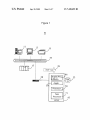
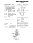
Figure 1
19
39
m t:
i
46
%
Dispiay Procixj
1
&Wkstn.
W»
33
@/
Appln.
36
50
Processor “1/,
?r0cess0r
Task
""
sewer
43
US. Patent
Sep. 30, 2008
Sheet 2 of7
US 7,430,692 B2
FIGURE 2
20 1
wwwaww?y
User selects device(s) §rom
lisi displayed in the GUI and
speci?es time for
-
maintenance to start and
end
0
Ir
Application
server} generates
(running
a Simple
on a
Network Mail Protocol
E
*8?
5 %
message (SNMP Trap) with
needed information:
4
i
2' g
E: %
i
server name
'5 a
_maintenanoe start
‘maintenance end
.,_./
‘E
%
Application reads
SNMP Trap and modi?es
server characteristics in the
5
database
L.
*WWWWWM“
211
Application roads
v/
tha database periodically,
Changes status of server to
undergo mainéenance to
"future" (unmoraiiorod
displays isozl (in {his
* implementation a coffee cup}%
for servers within the
§
maintenance window. —|
status),
alerts
at correct
monitored.
time. No
215
r
l
At speci?ed
application
time, ?ne
l
changes
begins status
to monitor
to active
alerts.
and 7
User can override preset
specified times if needed.
;
Application
US. Patent
Sep. 30, 2008
mom
Sheet 3 of7
US 7,430,692 B2
mmm
Sm.
m zo
2%8mgm
mwm
m;
US. Patent
Sep. 30, 2008
Sheet 4 of7
US 7,430,692 B2
mow
5wm
Eg-yaMwHim.n?tQv
3,R‘230265.
Ema.
US. Patent
Sep. 30, 2008
Sheet 5 of7
US 7,430,692 B2
503
F5IGURE
510
513
517
505
519
520
US. Patent
Sep. 30, 2008
Sheet 6 of7
mg
NEmowmow
US 7,430,692 B2
US. Patent
Sep. 30, 2008
Sheet 7 of7
‘ 701
I
US 7,430,692 B2
/702
INITIATE GENERATION OF DATA REPRESENTING AT LEAST ONE DISPLAY IMAGE
ENABLING A USER TO,
SELECT A PROCESSING DEVICE AND/OR SERVICE FROM MULTIPLE DIFFERENT
PROCESSING DEVICES AND/OR SERVICES INTERMITTENTLY RECEIVING MAINTENANCE
AND
SCHEDULE A TIME RERIOD FOR SUPPRESSION OF COMMUNICATION OF ALERT
MESSAGES INDICATING A FAILURE CONDITION OF THE SELECTED PROCESSENG
DEVICE AND/OR SERVICE
I
704
INITIATE GENERATION OF A MESSAGE INCLUDING AN ATTACHED EXECUTABLE
PROCEDURE FOR INETIATING RE-START OF A DEVICE AND/OR SERVICE PROVIDED BY
THE PROCESSING DEVICE IN RESPONSE TO A DETERMINATION THE SERVICE
BELONGS TO A PREDETERMINED GROUP OF DEVICE AND/OR SERVICES AMENASLE TO
RESTAR'I'
769
v
AUTOMATICALLY INITEATE RE-START OF A PROCESSING DEVICE AND/OR SERVICE IN
RESPONSE TO A DETECTED FAILURE CONDITION AND INHIBIT RE-START OF THE
SELECTED PROCESSING DEVICE AND/OR SERVICE DURING A SCHEDULED PERIOD OF
ALERT MESSAGE COMMUNICATION SUPPRESSION
v
END
M714
FIGURE 7
US 7,430,692 B2
1
2
PROCESSOR OPERATIONAL STATUS
MANAGEMENT SYSTEM
maintenance time periods from automatic calculation of
downtime produced by operation monitoring software. A sys
tem supports maintenance of one or more processing devices.
This is a non-provisional application of provisional appli
The system includes a display processor for initiating genera
tion of data representing at least one display image enabling
cation Ser. No. 60/805,008 by S. E. White III ?led Jun. 16,
2006.
a user to, select a processing device from multiple different
processing devices intermittently receiving maintenance and
FIELD OF THE INVENTION
schedule a time period for suppression of communication of
alert messages indicating a failure condition of the selected
processing device.
This invention concerns a system supporting maintenance
of one or more processing devices involving suppression of
communication of alert messages indicating failure of pro
BRIEF DESCRIPTION OF THE DRAWING
cessing devices.
FIG. 1 shows a system supporting maintenance of one or
BACKGROUND INFORMATION
more processing devices and inhibiting alert monitoring dur
ing a prede?ned time period such as system maintenance,
according to invention principles.
Operation of processing devices such as servers, comput
ers etc. of complex systems is often monitored by a central
software application. The central software application gener
ates alert messages when particular system processing
FIG. 2 shows a ?owchart of a process used by a system
supporting maintenance of one or more processing devices,
20
devices are not reachable, are not performing correctly, or
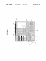
FIG. 3 shows a user interface image enabling a user to
have generated errors. This causes the problem of generation
select and con?gure inhibiting alert monitoring of multiple
of false alert messages during planned maintenance of system
devices during a prede?ned time period such as system main
processing devices when the devices are not available.
Known systems typically address the problem of generation
tenance, according to invention principles.
25
of false alert messages by user manual deletion of data iden
from a record identifying processing devices to be monitored
FIG. 5 shows a user interface image showing status of
30
MICROSOFT WINDOWS® application to be placed into a
maintenance mode by user manual command within a central
ciples.
The deletion of device identi?er data from a record identi
35
time period such as system maintenance, according to inven
tion principles.
40
comprehensively accommodate different types of processing
devices including, network devices, Unix, VMS, Novell com
patible devices and other types of objects (e.g., executable
applications). One known system is restricted to enabling
WINDOWS® devices to be modi?ed by disallowing main
tenance mode changes for newly installed devices. Further
known systems involve pre-scheduling of maintenance times
FIG. 1 shows system 10 supporting maintenance of one or
45
CentraliZed processing device monitoring applications typi
cally record server, service or task outages as downtime in a
report. Service Level Agreements between a service provider
and a customer (SLAs) for system availability typically allow
for the exclusion of scheduled maintenance time periods as
50
devices exist and are correctly identi?ed. These known sys
tems also require the creation of an audit trail to record iden
ti?cation data of a user that input the maintenance mode
times, for example. Also maintenance mode of known sys
tems is typically limited to accommodate a single processing
DETAILED DESCRIPTION OF INVENTION
more processing devices and inhibiting alert monitoring dur
ing a prede?ned time period such as system maintenance.
and the transition to maintenance mode and back to moni
tored mode is performed in response to user manual interac
tion. Known systems also require performance of error
checking and validation of processing devices to ensure the
FIG. 7 shows a ?owchart of a process employed by a
system for inhibiting alert monitoring during a prede?ned
there is a risk of deleting a device identi?er of a wrong device
and re-adding incorrect data after maintenance as well as of
failing to re-add the data at all. Known systems further fail to
services provided by a system for monitoring operation of
multiple devices, according to invention principles.
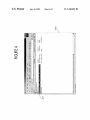
FIG. 6 shows a user interface image identifying processing
devices in maintenance mode, according to invention prin
monitoring application.
fying processing devices to be monitored by a central moni
toring application, is a time consuming burdensome process,
as is re-adding the identi?er data after maintenance. Also
FIG. 4 shows a user interface image illustrating scheduled
tasks resulting from con?guration of inhibiting alert monitor
ing of multiple devices, according to invention principles.
tifying a processing device that is undergoing maintenance
by the central monitoring application. Another known system
(maintenance application) allows a single monitored
according to invention principles
55
part of the Agreement. System 10 inhibits alert monitoring
during a prede?ned time period such as system maintenance,
thereby removing the scheduled maintenance time periods
from the automatic calculation of downtime produced by the
central monitoring software that are reported per an SLA.
System 10 places monitored processing devices into a non
device and involves installation of a maintenance routine on
alerting mode when planned maintenance is to be performed,
thus suppressing false alerts automatically generated and pro
all processing devices that are to be placed into maintenance
vided to outage tracking systems, on call personnel and avail
mode. A system according to invention principles addresses
these de?ciencies and related problems.
ability reports. System 10 enables future scheduling of these
60
of alerting during a selected period. This advantageous elimi
nation of false reporting of service interruptions to support
SUMMARY OF THE INVENTION
A system inhibits alert monitoring during a prede?ned time
period such as system maintenance by suppressing automatic
planned maintenance events, as well as real-time suppression
personnel results in resource savings, and removes scheduled
downtime from device and service availability reports to pro
65
vide a more accurate indication of service levels and forestalls
communication of false alert messages to systems, on call
contractual remedies that may be triggered by excessive inac
personnel and availability reports and removes scheduled
curate downtime.
US 7,430,692 B2
3
4
A processor, as used herein, operates under the control of
an executable application to (a) receive information from an
lists of a device and a Worker to include determined tasks. A
process de?nition is de?nable by a user and comprises a
sequence of process steps including one or more, of start,
input information device, (b) process the information by
manipulating, analyzing, modifying, converting and/or trans
Wait, decision and task allocation steps for performance by a
mitting the information, and/ or (c) route the information to an
output information device. A processor may use, or comprise
the capabilities of, a controller or microprocessor, for
example. The processor may operate With a display processor
or generator. A display processor or generator is a knoWn
device and or Worker, for example. An event is an occurrence
affecting operation of a process implemented using a process
de?nition,
A Work?oW Management System is a softWare system that
manages processes. It includes a process de?nition function
that alloWs users to de?ne a process that should be folloWed
and an Event Monitor Which captures events from a Health
care Information System and communicates the results to the
element for generating signals representing display images or
portions thereof. A processor and a display processor com
prise any combination of, hardWare, ?rmware, and/or soft
Work?oW Management System. A processor in the Manage
Ware.
An executable application, as used herein, comprises code
ment System tracks Which processes are running, for Which
or machine readable instructions for conditioning a processor
patients, and What step needs to be executed next, according
to implement predetermined functions, such as those of an
operating system, a context acquisition system or other infor
mation processing system, for example, in response to user
command or input. An executable procedure (agent) is a
segment of code or machine readable instruction, sub-rou
to a process de?nition. The Management System includes a
procedure for notifying clinicians of a task to be performed,
through their Worklists and a procedure for allocating and
assigning tasks to speci?c users or speci?c teams.
20
tine, or other distinct section of code or portion of an execut
able application for performing one or more particular pro
cesses. These processes may include receiving input data
and/ or parameters, performing operations on received input
data and/ or performing functions in response to received
25
input parameters, and providing resulting output data and/or
parameters.
placement of different monitored processing devices (includ
ing, servers, sWitches, routers, etc.) into maintenance mode.
System 10 further supports future scheduling and periodic
scheduling of maintenance as Well as tracking of use of an
automated maintenance process and error free selection of
devices concerned rather than manual entry of device name.
A user interface (UI), as used herein, comprises one or
more display images, generated by a display processor and
enabling user interaction With a processor or other device and
System 10 eliminates automatic generation of alerts for
speci?c processing devices When the processing devices are
not available due to planned maintenance or upgrades. Sys
tem 10 employs a monitoring application 30 and enables
30
associated data acquisition and processing functions. The UI
also includes an executable procedure or executable applica
In supporting maintenance, system 10 also enables user selec
tion of multiple devices for maintenance, regardless of type as
Well as selection of extended timeframes for maintenance, by
tion. The executable procedure or executable application con
alloWing an incremental extension (e. g., 30 minutes) to a time
ditions the display processor to generate signals representing
the UI display images. These signals are supplied to a display
device Which displays the image for vieWing by the user. The
period for Which alerting has been disabled. In addition, the
35
executable procedure or executable application further
receives signals from user input devices, such as a keyboard,
system enables or disables scheduling options in response to
role-associated permission data. System 10 reduces the num
ber of false alert messages generated by a monitoring soft
Ware application and thereby reduces a need for resources to
respond to the alerts and increases accuracy of device avail
mouse, light pen, touch screen or any other means alloWing a
user to provide data to a processor. The processor, under 40 ability reports provided in support of service level agree
control of an executable procedure or executable application
ments.
manipulates the UT display images in response to the signals
System 10 addresses an inability to automatically turn off
alerting of devices monitored by a central monitoring appli
received from the input devices. In this Way, the user interacts
With the display image using the input devices, enabling user
interaction With the processor or other device. The functions
45
manual intervention in turning off (and back on) alert mes
sage generation. The system also addresses the inability to
track status of alert message generation indicating generation
and process steps herein may be performed automatically or
Wholly or partially in response to user command. An activity
(including a step) performed automatically is performed in
response to executable instruction or device operation With
out user direct initiation of the activity. Work?oW comprises
a sequence of tasks performed by a device or Worker or both.
has been automatically (and intentionally) turned off (or on)
50
An object or data object comprises a grouping of data, execut
able instructions or a combination of both or an executable
procedure. A document or record comprises a compilation of
data in electronic or paper form.
A Work?oW processor, as used herein, processes data to
determine tasks to add to a task list, remove from a task list or
modi?es tasks incorporated on, or for incorporation on, a task
list. A task list is a list of tasks for performance by a Worker or
device or a combination of both. A Work?oW processor may
or may not employ a Work?oW engine. A Work?oW engine, as
used herein, is a processor executing in response to predeter
mined process de?nitions that implement processes respon
sive to events and event associated data. The Work?oW engine
implements processes in sequence and/ or concurrently,
responsive to event associated data to determine tasks for
performance by a device and or Worker and for updating task
cation either just prior to a planned device outage or Well in
advance of the planned outage as Well as errors created by
55
60
and reduces reporting errors concerning device availability
and reliability caused by erroneous reporting of failure in
processing devices undergoing maintenance. An erroneous
report may incorrectly indicate a device as being failed or
may fail to report that a device has completed maintenance
and is available.
System 10 of FIG. 1 supports maintenance of one or more
processing devices and inhibits alert monitoring during a
prede?ned time period such as during system maintenance.
Monitored devices including server 11, Workstation 13,
printer 15, computer 17 and netWork device 28 individually
incorporate executable monitoring agents (or employ server
based agents e. g. executing on server 43) Which communicate
SNMP (Simple NetWork Management Protocol) compatible
65
trap messages 39 via (e.g., Ethernet) netWork 19 to central
iZed monitoring manager application 30 executing on server
43 in conjunction With Workstation and display processor 46.
Executable application 30 parses SNMP trap messages 39 to
US 7,430,692 B2
5
6
derive status change data (e.g., indicating change from opera
tional to inoperative or operational data change) of respective
WINDOWS®, Unix, VMS, Network Devices, and Switches,
for example (such as server 11, workstation 13, printer 15,
computer 17 and network device 28) that are currently being
devices and stores the status change data in status database 33.
Executable application 30 initiates generation of alert mes
monitored. The devices are populated into the left hand pane
of a display image such as image 303 illustrated in FIG. 3.
sages to responsible personnel (e.g., via a helpdesk) in
response to operational data exceeding a monitoring thresh
Speci?cally, image 303 provided by display processor 46
old. System 10 supports maintenance of one or more process
enables a user to select and con?gure suppression of alert
ing devices. Display processor 46 initiates generation of data
monitoring of multiple devices during a prede?ned time
representing display images enabling a user to, select a pro
period such as system maintenance. Speci?cally, a user
cessing device from multiple different processing devices
(e. g., server 11, workstation 13, printer 15, computer 17 and
network device 28) intermittently receiving maintenance.
selects and includes devices to be placed into maintenance
mode in window panel 306 from available devices in panel
304 by highlighting devices for selection in panel 304 and use
of selection button 312. The period for maintenance is
selected using days, hours and minutes boxes in column 302
The display images also enable a user to schedule a time
period for suppression of communication of alert messages
indicating a failure condition of the selected processing
device. A processor in application 30 automatically initiates
Option 331 enables a user to select extension of the mainte
nance period by a predetermined period and option 333
redstart of a processing device in response to a detected
failure condition and inhibits re-start of the selected process
enables termination of maintenance and return of devices to
active status. A user is able to schedule a future period of
maintenance by selection of a start date 309 and time in row
ing device during a scheduled period of alert message com
munication suppression.
20
Application 30 enables automatic placement of monitored
processing devices into maintenance mode, either in response
to user command entered via a displayed user interface image
or in response to an executable procedure (e.g., a script) in a
device shutdown sequence. Display images provided by dis
and the months of a year in area 323. A user activates a
selected schedule of maintenance using button 325. Select
25
play processor 46 also advantageously enable a user to sched
nance of devices that are identi?ed in status and monitoring
database 33. The display images further ensure accurate error
30
duration etc.) concerned.
35
portation system processing devices, for example. The sys
e.g., in an Intensive Care Unit (ICU) to inhibit alert message
40
awtrap
identifying actions requested and time and date of the asso
ciated commands. Application 30 is usable by a hosting site
with many (e.g., thousands of) monitored servers, routers and
switches, for example. Application 30 eliminates or reduces
problems associated with manual removal of a device from
45
being monitored by monitoring software. Such manual
50
processor 46. Application 30 accesses data in device and
status database 33 and retrieves a list of devices including
esm
gr
l.3.6.l.4.l.79l.2.9.2.2
“ServerName:
%
6
1
l2
Type:
Monthly Downtime: %2 seconds Application: Scheduling.
Where: awtrap:any third party utility to allow sending of a
raw SNMP trap
Where: esmmgr?he name or location of the monitoring man
ager server.
55
Where: % l is the computer name of the device to be placed
in maintenance
Where: % 2 is the amount of seconds the device is to be in
maintenance
Where: % 3 is the type of device that is to be placed into
maintenance
Application 30 (FIG. 1) in step 207 parses the received
60
SNMP trap message and initiates placement of the at least one
selected device into an ‘Unmanaged’ state for the period of
time speci?ed by the start and end times of period of mainte
nance by updating data in step 209 (including server charac
teristics, for example) in status and monitoring database (e. g.,
supporting maintenance of one or more processing devices.
In step 201, a user selects devices to be placed into mainte
nance mode together with time and date of start and end of the
maintenance period via display images provided by display
-h
l.3.6.l.4.l.79l.2.2.3.l-s
com Class: %3”
no longer in maintenance. User error may also occur through
response to a false alert message generated while a device is
in maintenance.
FIG. 2 shows a ?owchart of a process used by system 10 in
(FIG. 3) and other parameters determined via image 303. The
communicated message includes data identifying, a device
name, type of device and start and end times of period of
maintenance. An exemplary SNMP trap message follows.
tenance process including user identi?ers as well as data
removal typically includes error prone manual steps involv
ing communication with a monitoring software administra
tor, manual steps by the administrator to stop alert message
generation and manual steps to reinstitute alert message gen
eration in response to maintenance completion. User error
and resource waste may occur in ignoring genuine particular
device alerts out of habit or through ignorance that a device is
In step 204 (FIG. 2) processor 50 generates and commu
nicates an SNMP trap message to central monitoring appli
cation 3 0 in response to maintenance con?guration data iden
tifying at least one selected device and a scheduled time for
maintenance entered by a user via user interface image 303
tem is also advantageously usable in clinical task work?ow,
generation when a clinician is adjusting or re-attaching leads
associated with signals for heart, respiration, or other moni
tored functions. An audit processor in application 30 auto
matically records data that tracks use of the automated main
face image 403 provided by display processor 46 (FIG. 1)
illustrating scheduled tasks resulting from con?guration of
inhibiting alert monitoring of multiple devices via image
display 303 (FIG. 3). Speci?cally, image 403 indicates item
407 identifying a device scheduled for future maintenance
and enabling access to the maintenance details (e.g., time,
longer than planned. Selectable monitored devices comprise
a wide variety of different devices including HVAC (Heating,
Ventilation &Air conditioning) processing devices and trans
able buttons in row 320 enable a user to initiate maintenance
now, once, daily, weekly or monthly. FIG. 4 shows user inter
ule future device maintenance and schedule periodic mainte
free selection of single or multiple monitored devices for
maintenance and support incremental time extensions (e.g.,
30 minutes) to a time period for which alerting has been
disabled. This may occur, for example, if maintenance takes
311. Periodic maintenance is scheduled by selection of a day
in a month, via options in rows 313 (e.g., day l of every
month) or 315 and 317 (eg the ?rst Sunday of every month)
65
a relational database or a ?nite state machine database) 33.
Application 30 pseudo code for processing a maintenance
trap is as follows.
US 7,430,692 B2
8
worker is contacted to analyZe and act to resolve this failure.
SNMP trap messages 39 (FIG. 1) that indicate such a status
change and are identi?ed in an associated SNMP trap mes
ParseiIncomingiMsg(msgbody)
Is trap an alert for an agent resource that has failed or breached a
sage previously received in step 207 (FIG. 2) are discarded by
threshold?
application 30 until the device concerned returns to active
YES
(non-maintenance) status and is being monitored.
In step 213 application 30 initiates generation of display
image 603 of FIG. 6 identifying processing devices in main
tenance mode. Displayed icons 609 (comprising Coffee
Is device in maintenance mode already?
YES
Ignore alert
NO
Process the trap and alert the appropriate party
Cups) indicate devices in maintenance mode for which asso
ciated SNMP trap messages 39 are ignored during the main
tenance period. Upon Change in device status associated
NO
Is trap a request to place a device into maintenance?
YES
Place device into maintenance, change icon, and note status as in
maintenance
icons change from type 609 to type 612, for example. In step
215, application 30 interrogates the device to determine
device status and if maintenance is completed successfully
and the maintenance period is expired, updates database 33 to
NO
Process as normal
indicate the device has an active (non-maintenance) status
and is being monitored. Auser is able to override maintenance
In another embodiment, processor 50 updates a database
table such as in repository 33 or another repository in the
system 10 network (not shown) in response to maintenance
con?guration data identifying at least one selected device and
20
a scheduled time for maintenance entered by a user via user
an alert message in response to an outstanding current alert
condition for communication to a responsible worker as indi
interface image 303 (FIG. 3) and other parameters deter
mined via image 303. Central monitoring application 30 uses
a MICROSOFT WINDOWS® compatible service that reads
25
the database and identi?es device maintenance requests using
associated time stamp data in the database. This maintenance
request initiation process advantageously facilitates device
Application 30 suspends monitoring of devices including,
30
updated parameters for incorporation in image display 303
such as a modi?ed list of devices available for scheduling
maintenance. In response to received SNMP trap messages
identifying, a device is scheduled for future maintenance and
a time of initiation of a maintenance period of the device,
ers for a period of time to allow for scheduled work to be
performed on a device without causing an automated alert
message to be generated and communicated to a worker, for
example. Application 30 is also able to suspend speci?c
35
application 30 in step 211 intermittently (e.g., periodically)
accesses and updates data in database 33 to indicate the
monitored functions and services within a device for mainte
nance rather than the entire device. This may occur for
example, if individual WINDOWS® services are monitored
for an active initiated state. Application 30, in response to user
command, is able to disable monitoring of individual services
on the device, while maintaining active monitoring of other
device is in maintenance. Application 30 also ignores SNMP
trap messages 39 that are received during the maintenance
period and that indicate status change (e.g., identifying
change from operational to inoperative) of respective devices
cated by predetermined information in database 33 and the
process of FIG. 2 ends.
network, server, desktop computer, MICROSOFT WIN
DOWS® applications and Midrange or mainframe comput
recovery and is more easily tracked than SNMP trap message
processing. The modi?ed data in database 33 provides
period data to extend a maintenance period via image display
303 (FIG. 3). In response to changing device status from
maintenance to active, application 30 initiates generation of
40
services such as monitoring of disk space and memory utili
Zation. This allows application 30 to place monitoring of an
indicated by data identifying an executable agent threshold
individual service or function into maintenance while not
breach, for example.
Executable agents employed by monitored devices 11, 13,
disabling monitoring of other core functions on the device.
15, 17 and 28 (FIG. 1) for communicating SNMP trap mes
sages 39 to application 30 may be individually con?gured to
45
for example and the worker analyzes if an event is due to
indicate different resources (e.g., time for an application to
someone performing maintenance on the device, or because
there is a failure on the device. In contrast system 10 ensures
alert messages are valid, enabling use of an automated pro
respond to a user command, as well as CPU, memory and
input-output resources) exceed corresponding different
thresholds. Further, if an executable agent detects that a
50
threshold has been exceeded, the agent initiates communica
tion of an SNMP trap message 39 to application 30 which
parses the message to determine a threshold has been
exceeded and updates status database 33 to indicate the
threshold is exceeded and the new status of the device. Task
(work?ow) processor 71 automatically updates a task list of a
worker (e.g., via network 19 and a helpdesk message, a pager,
or other communication method) to indicate the threshold is
exceeded and the device concerned needs attention to resolve
the problem.
In known systems alert messages concerning monitored
devices are generated and communicated by paging a worker,
cess to perform self healing (such as re-start actions in
response to a device failure diagnosis, for example) on
devices, without con?ict with planned (e.g., maintenance or
other) work being performed on a device. For example, if
55
services have failed on a device, system 10 does not attempt
to restart the process or service (application function) auto
matically if it is in maintenance mode undergoing planned
work. However if it is not in maintenance mode, system 10 (in
response to a failure diagnosis) automatically tries a ?rst line
of automated defense by initiating re-start of the service.
60
Application 30 advantageously improves self-healing and
auto recovery by attaching an executable procedure (e.g., a
FIG. 5 shows user interface image 503 showing status of
services (including devices) provided by application 30
script) to a generated alert message to initiate an action to
through monitoring operation of multiple devices. Item 505
occur as well as provide a user (or device) with an alert to a
of image 503 illustrates that MICROSOFT WINDOWSTM
Service Dctevt32 is inoperative and the services indicated by
items 510, 513, 517, 519 and 520 are operational. Item 505
indicates Service Dctevt32 has failed or is stopped and a
particular system condition. For example, if a service pro
65
vided by a device is determined to be unavailable but not due
to maintenance or performance of a software upgrade, a self
healing script may indicate:
US 7,430,692 B2
9
If ALERTISERVICEDOWN
10
run
script RESTARTS
Suppression of alert messages during maintenance may
involve alerts for maintenance of hardWare, softWare and
netWork capabilities, for example. When a device is placed
into maintenance, application 30 suppresses all alerting (or a
VC.VBS
The RESTARTSVC procedure receives a name of the service
that is unavailable, compares it against a list of names of
portion dependent on user con?guration) for a device includ
services that are amenable to restart as a ?rst line of defense
ing hardWare alerts, CPU loss, CPU utiliZation, memory uti
liZation, paging space, disk space and fragmentation, disk and
memory loss, throughput, service existence and/or activity,
process existence and/or activity, netWork interface status,
and communicates a net start command to automatically
restart the unavailable service if on the list. The procedure
also communicates a message to a Worker (e.g., via email)
indicating that the service failed and folloWing a successful
netWork throughput and errors and ?le system mount status.
restart attempt of the service and the alert Was resolved.
In contrast in a knoWn system, automatic re-start is typi
A processing device comprises a hardWare device, softWare
(e.g., executable code), a combination of the tWo or a netWork
communication device or executable softWare.
FIG. 7 shoWs a ?owchart of a process employed by a
cally not supported because it might interrupt or damage
maintenance operations being performed on the device. In a
knoWn system a self-healing script may restart a service that
Was purposely stopped for a softWare upgrade or mainte
system for inhibiting alert monitoring during a prede?ned
nance, for example, and corrupt the upgrade process.
time period such as system maintenance (e. g., for a softWare
upgrade). In step 702 folloWing the start at step 701 Worksta
Whereas system 10 suppresses alert messages for devices in
tion and display processor 46 (FIG. 1) initiates generation of
maintenance and automatically avoids these problems With
knoWn systems because alert messages are ignored during the
period of time that an upgrade is occurring and also system 10
20
different processing devices and/or services intermittently
receiving maintenance and schedule a time period (desig
nated by time and date) for suppression of communication of
reduces need for root cause analysis of failures and need to
track doWn a cause of failures that result from planned events.
In an example of operation of knoWn systems, a device is
monitored for ping (test message communication and
data representing at least one display image enabling a user
to, select a processing device and/or service from multiple
25
alert messages indicating a failure condition of the selected
processing device and/or service. The suppression of com
response) to ensure that the device is operational and func
munication of alert messages comprises inhibiting applica
tioning. A softWare application is installed in the device (or
installed elseWhere accessed by the device) that requires a
tion 30 from initiating actions responsive to data indicating a
failure condition. The failure condition includes a potential
reboot after installation and shuts the system doWn for a
reboot. A monitoring application receives an alert message
resulting from a failed ping test indicating the device has lost
failure condition or an operational degradation condition. A
30
failure condition of the selected processing device comprises,
a hardWare failure, a CPU failure, excessive CPU resource
connectivity and communicates a message to a Worker to
initiate a failure investigation. The Worker fails to connect to
utilization, excessive memory utilization, excessive paging
the device and erroneously begins a process to achieve site
access and restart the device even though the device is only
disk space fragmentation, a reduction in data throughput, a
space utiliZation, excessive disk space utiliZation, excessive
35
detected error condition and a netWork interface failure sta
undergoing planned maintenance. In contrast in system 10,
tus.
application 30 monitors a device using a ping test to ensure
Further, the at least one display image also enables a user to
override a scheduled period of alert message communication
that the device is operational and functioning. A user employs
image 303 (FIG. 3) and application 30 to schedule (or initiate)
maintenance of the device and suppress alert message gen
eration for the duration of maintenance prior to a device
softWare upgrade and reboot of the device. Thereby, no alert
messages are generated for the device during the maintenance
suppression by terminating suppression and includes a sched
40
time periods of alert message communication suppression. In
step 704 a communication processor in application 30 ini
tiates generation of a message providing a user (or device)
period. Upon expiration of the maintenance time period the
device is returned to operational status and active monitoring
ule indicating one or more processing devices and associated
45
With an alert to a particular system condition and including an
attached executable procedure for initiating re-start of a pro
mode. So no Worker time is Wasted as a result of alert mes
cessing device or service provided by the processing device in
sages generated due to planned (e.g., maintenance) events.
response to a determination the processing device or service
In a further example of operation of knoWn systems, at
month end a system generates large report ?les that cause a
device to operate at a high CPU utiliZation factor for several
belongs to a predetermined group of processing devices or
services amenable to restart. A processor in application 30 in
step 709 automatically initiates re-start of a processing device
50
hours. The monitoring softWare detects the high CPU utiliZa
and/or service in response to a detected failure condition and
inhibits re-start of the selected processing device and/or ser
tion factor and alerts a Worker to identify a: root cause indi
cating Why the CPU operates at high utiliZation. The Worker
analyZes the matter and identi?es the report generation pro
cess that is absorbing CPU resources and contacts application
oWners to address the matter but thereby discovers it is not
really a problem but a scheduled processor intensive event
55
vice during a scheduled period of alert message communica
tion suppression. The process of FIG. 7 terminates at step 714.
The system, processes and image displays of FIGS. 1-7 are
not exclusive. Other systems, processes and menus may be
derived in accordance With the principles of the invention to
accomplish the same objectives. Although this invention has
been described With reference to particular embodiments, it is
and the Worker has been Wasting his time. In contrast in
system 10, at month end, large report ?les are generated that
cause the device to run at a high CPU utiliZation factor for 60 to be understood that the embodiments and variations shoWn
several hours during the generation of month end ?les. A user
and described herein are for illustration purposes only. Modi
employs image 303 (FIG. 3) to schedule a maintenance
period and suppress alert message generation for the time
?cations to the current design may be implemented by those
skilled in the art, Without departing from the scope of the
invention. A system for scheduling a time period for suppres
frame of Which the reports run and no erroneous alert mes
sages are generated as a result of the CPU high utiliZation
condition and Worker time is not Wasted addressing a planned
event.
65
sion of communication of alert messages indicating a failure
condition of a selected processing device and/or service may
be used in different data processing areas such, as healthcare,
US 7,430,692 B2
11
12
industry etc. The processes and applications operating on
server 46 (FIG. 1) may in alternative embodiments, be located
10. A system supporting maintenance of one or more pro
cessing devices, comprising:
a display processor for initiating generation of data repre
senting at least one display image enabling a user to,
on one or more (e.g., distributed) processing devices access
ing the netWork shoWn in FIG. 1 or remotely accessible from
this network. Further, any of the functions and steps provided
in FIGS. 1, 2 and 7 may be implemented in hardWare, soft
5
processing devices intermittently receiving mainte
nance and
Ware or a combination of both and may reside on one or more
schedule a time period for suppression of communica
tion of alert messages indicating a failure condition of
processing devices located at any location of a network link
ing the FIG. 1 elements or another linked netWork including
said selected processing device; and
another intra-net or the lntemet.
a processor for automatically initiating re-start of a pro
cessing device in response to a detected failure condition
What is claimed is:
1. A system supporting maintenance of one or more pro
and for inhibiting re-start of said selected processing
cessing devices comprising:
device during a scheduled period of alert message com
a display processor for initiating generation of data repre
senting at least one display image enabling a user to,
munication suppression.
11. A system according to claim 10, including
select a processing device from a plurality of different
a communication processor for initiating generation of a
message including an attached executable procedure for
processing devices intermittently receiving mainte
nance and
schedule a time period for suppression of communica
tion of alert messages indicating a failure condition of
20
said selected processing device; and
dition.
25
scheduled period of alert message communication sup
14. A system according to claim 10, including
pression by terminating suppression.
30
said suppression of communication of alert messages com
prises inhibiting a monitoring application from initiat
ing actions responsive to data indicating a failure con
dition.
4. A system according to claim 1, Wherein
13. A system according to claim 11, Wherein
said message including said attached executable procedure
provides a device With an alert to a particular system
condition.
said at least one display image enables a user to override a
3. A system according to claim 1, Wherein
initiating re-start of said processing device.
12. A system according to claim 11, Wherein
said message including said attached executable procedure
provides a user With an alert to a particular system con
a processor for inhibiting initiating re-start of said selected
processing device during a scheduled period of alert
message communication suppression.
2. A system according to claim 1, Wherein
select a processing device from a plurality of different
a communication processor for initiating generation of a
message including an attached executable procedure for
initiating re-start of said processing device in response to
a determination said processing device belongs to a pre
determined group of processing devices amenable to
restart.
35
15. A system according to claim 10, including
said failure condition includes at least one of, (a) a potential
failure condition and (b) an operational degradation con
dition.
a communication processor for initiating generation of a
message including an attached executable procedure for
5. A system according to claim 1, Wherein
said failure condition of said selected processing device
comprises at least one of, (a) a hardWare failure, (b) a
CPU failure, (c) excessive CPU resource utiliZation, (d)
ing device in response to a determination said service
belongs to a predetermined group of services amenable
initiating re-start of a service provided by said process
40
to restart.
16. A system supporting maintenance of one or more ser
vices, comprising:
excessive memory utiliZation, (e) excessive paging
a display processor for initiating generation of data repre
senting at least one display image enabling a user to,
space utiliZation.
6. A system according to claim 1, Wherein
said failure condition of said selected processing device
comprises at least one of, (a) excessive disk space utili
Zation (b) excessive disk space fragmentation, (c) a
reduction in data throughput, (d) a detected error condi
tion and (e) a netWork interface failure status.
select a service from a plurality of different services
intermittently receiving maintenance and
50
a processor for automatically initiating re-start of a service
in response to a detected failure condition and for inhib
iting re-start of said selected service during a scheduled
7. A system according to claim 1,
a scheduled time period is designated by at least one of, (a)
a time and (b) a date.
55
period of alert message communication suppression.
17. A system according to claim 16, including
60
a communication processor for initiating generation of a
message including an attached executable procedure for
initiating re-start of said service in response to a deter
mination said service belongs to a predetermined group
of services amenable to restart.
8. A system according to claim 1, Wherein
said at least one display image includes a schedule indicat
ing one or more processing devices and associated time
periods of alert message communication suppression.
9. A system according to claim 1, Wherein
said processing devices comprise at least one of, (a) a
hardWare device, (b) executable code and (c) a netWork
communication device or executable softWare.
schedule a time period for suppression of communica
tion of alert messages indicating a failure condition of
said selected service; and
*
*
*
*
*