1
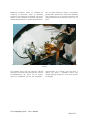
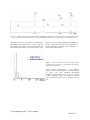
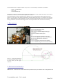
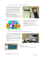
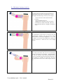
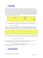
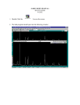
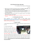
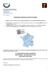
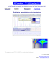
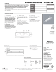
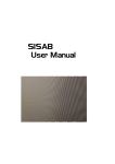
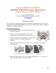
X-ray multilayers
optic
User’s manual
INEL
. Z.A C.D 405 – 45410 ARTENAY
& +33.(0)2.38.80.45.45 Æ 0+33.(0)2.38.80.08.14
) [email protected]
http://www.inel.fr
S
UMMARY
PRESENTATION
1–2
EXAMPLES
3–4
SETUP
5 -10
1 – DESCRIPTION
2 – SETTING THE MECHANICS
2a – REMOVING THE MONOCHROMATOR MECHANICS
2b – SETTING THE MIRROR/MONOCHROMATOR MECHANICS
2c – DIFFERENTS KINDS OF SETUPS
2d – ADJUSTEMENTS
2e – MIRROR CHARACTERISTICS
6
6 -10
7
7
8
9
10
X-ray multiplayer optic – User’s manual
Sheet 1/11
PRESENTATION
X-ray multiplayer optic – User’s manual
Sheet 2/11
Multilayers parabolics mirrors for x-radiation are
comprised of nanometric stacks of alternating
transparent and absorbent compounds. The mirror
captures a wider solid angle of incoming beam than a
standard flat germanium or graphite monochromator
and its graded multilayers output a concentrated
parallel beam. Results have shown that depending
upon experiment type, for equivalent resolution and
settings, intensities can increase by factors of 3 to 7
times.
Figure 1 : Mirror mounted on the Inel diffractometer, located between the tube shield and monochromator
housing.
.
The parabolic mirror does not offer Kα1 and Kα2
separation. We therefore have designed our system to
be multifunctional. The mirror can be used by
itself, or in combination with the flat germanium
monochromator if an intense, pure Kα1 beam is
desired. (See figure 1.) Parabolics mirrors have
graded d-spacing designed to work with specifics
wavelengths.
X-ray multiplayer optic – User’s manual
Sheet 3/11
EXAMPLES
X-ray multiplayer optic – User’s manual
Sheet 4/11
Figure 2 : Comparison of silicon standard data (SRM640b) with the direct beam (line 2), the filtered direct beam
(line 3), and with the mirror (line 1). The experimental conditions were identical for the 3 measurements.
With the mirror (line 1), the intensity is double that of
the unfiltered direct beam (line 2). In line 1 only the
Kα1 and Kα2 contributions are present whereas with
the unfiltered direct beam, all energies in the copper
spectra, Kα1, Kα2, Kβ give diffraction contributions.
Using a nickel filter with the direct beam (line 3)
similar resolution is obtained, but the intensity is 5
time less than with the mirror.
Figure 3 : System comparison between setup with a
germanium crystal alone vs. germanium crystal plus
X-ray mirror in tandem.
Silver behenate diffractograms, 1 mm diameter
capillary, with mirror (black curve) and without the Xray mirror (red curve). Identical experimental
conditions (monochromator Ge 111, 40 kV - 30 mA,
Cu Kα1, spinning sample, 10 minutes acquisition
time). An intensity gain of 3.5 is evidenced in this
case.
X-ray multiplayer optic – User’s manual
Sheet 5/11
SETUP
X-ray multiplayer optic – User’s manual
Sheet 6/11
The Inel diffractometer equipped with the X-ray mirror, can beset belongs 3 differents possibilities:
- mirror + monochromator,
- mirror only,
- monochromator only.
The mirror is used as an intensifier of the primary beam, and is able to make parallel the primary beam (with 0.7
mm thickness). However, it is not able to separate kα1 and kα2.
The monochromator is able to separate the kα doublet, to give a monochromatic beam, but decreases the
intensity. It is the reason why that for high intensity and monochromatic beam, it is required to use the setup
Mirror + Monochromator. When high flux is necessary, then the monochromator can be removed. The third
setup is possible to do, but not interesting, because it corresponds to the first one with a low intensity.
1- DESCRIPTION
Figure 4 : description of the optics
1 : 4 screws for adjusting the mirror
2 : Monochromator housing
3 : 2 fine screws to adjust the height of the pipe
4 : Crossed slits
5 : 2 screws to rotate the whole optics
6 : pipe
7 : Screws for holding the translation of the pipe
8 : Fine screw to adjust the tilt of the monochromator
9 : Fine screw to adjust the tilt of the mirror
10: Mirror housing
11: 2 screws to open the monochromator housing
12: 3 screws behind fixing the monochromator housing
Figure 5 : Beam path and angles
on the Inel diffractometer using
the X-ray mirror, for the copper
radiation
2- SETTING THE MECHANICS
IMPORTANT : Each time user needs to dismount any mechanics, the power and the water cooling must be off.
X-ray multiplayer optic – User’s manual
Sheet 7/11
2a- REMOVING THE MONOCHROMATOR MECHANICS
-
Remove the cover of the monochromator, holding
the crystal and rotation system, by loosing in S1.
Remove the whole mechanics, by loosing
attachment screws on the tube shield in S2. Be
careful, the system is quite heavy. During the
loosing the mechanical safety shutter must be
jumped up [3]. Be careful to hold it during the
procedure.
Only the monochromator housing and the slits will be
dismount to set on the mirror assembly.
Slits are removed by loosing S4
Monochromator housing is dismounted by loosing
the M4 screw (S5) defining the rotation axis, in rear.
The pipe is dismounted as following scheme.
-
S6 allow to loose the "tube shield interface. It is
necessary to remove the "rear cover".
Instead of the " tube shield interface" will be set
the "mirror pipe".
In the next part are described the several
possibilities of configuration. In case of it is
necessary to remove the crystal itself, loose the S8
screws on the side.
2b- SETTING THE MIRROR/MONOCHROMATOR MECHANICS
-
-
-
Attach "A" the optics holder on the tube shield,
with S2 screws. Before tightening the plate, set the
"tube shield interface" and the " mechanical safety
shutter" [3].
Attach the "mirror housing" "B", by screwing S9.
Attach the part "C" (Monochromator housing and
slits system), with "S5" in "H1". Take care to
introduce the mirror pipe on the "Monochromator
housing"
Fix the slit on the new pipe assembly in S4.
Rear side of "C" part:
The screw on H2 must fix :
in "I" if the mirror only is used,
or in "II" if the assembly mirror/monochromator is used
X-ray multiplayer optic – User’s manual
Sheet 8/11
2c- DIFFERENT KIND OF SETUP
Figure 6 : Mirror + monochromator setup.
The angle between the beam coming from the mirror,
and the beam exiting to the monochromator is 27.28°.
This angle is fixed by using 3 screws (ref.12 on fig.4) :
-
1 screw for the axis of the monochromator
housing
1 screw maintaining the arm
1 handled screw to remove when we wish to
switch from one mode to the other. There are
only 2 positions allowed : straight or inclined at
27.28°.
Figure 7 : Mirror setup without monochromator.
The Germanium crystal must be removed from the
monochromator housing. The pipe and the mirror
surface must be on the same alignment (+/- 1.5°). For
this feature, we must use the handled screw behind. It
must be removed, to fixed the arm to the straight
position.
Figure 8 : Monochromator only
This setup can be done, but it is not very interesting,
because it is like the case of Mirror + monochromator,
but with less intensity. Then mirror housing must be
removed, and replaced the monochromator housing. A
pipe extension is available to increase the pipe size.
The angle between the source and the pipe, must be
27.3°.
X-ray multiplayer optic – User’s manual
Sheet 9/11
2d- Adjustements
2da- The mirror
The mirror can be aligned by using the screws 1 (S1) and the micro-screw 9 (MS9) (figure 4). We usually need
the MS9. S1 are used for adjusting the horizontally. MS9 is used for tilting the mirror, in order to get the
reflected beam. To adjust it, it is required to remove the monochromator housing cover (using 11), and replace it
with the cover containing the fluo-screen (see tool box). When it is fixed, put X-ray on, and check with a counter
that everything is safe. Turn MS9, to see the 2 differents beams : at low incidence (on the top-left of the fluoscreen) the direct beam must be seen. By turning MS9, it must disappeared and the reflected beam must appears
at 1.15° of incidence (The print must be displaced to the bottom right). When the print of the reflected beam is
selected (figure 9–3), switch off the X-ray, and replace the fluo-screen cover by the Germanium holder. Refers to
the monochromator adjustment for the second part.
Figure 9 : Prints appearing when MS9 is rotated counter clockwise. (1) is the full direct beam (top), (2) are
prints of direct beam (top) and weak reflected beam (bottom), (3) the full reflected beam.
2db- The monochromator
Put the fluo-screen on the fixed sample holder, in order to see the beam coming through the slits. Open in large
the vertical slit. Switch on X-rays. Turn the MS8 on the monochromator housing until the beam is found. The
different steps of the adjustment are described in figure 10. The best adjustment correspond to the scheme (3).
Figure 10 : Prints appearing when MS8 is rotated counter clockwise. (1) is the beginning of k α2, (2) is fully kα2
with a small amount of kα1, (3) is fully kα1, and (4) is a ended part of kα1. Then the beam must be adjusted as
(3).
2dc- Centering the beam between the slits
The following procedure is to close gradually the slit (Fv), and check that the beam is not "cut" by the slit. If it is
the case, move slightly up and down the pipe in order the center the beam on the slit axis.
2dd- Centering the whole optics on the diffracting axis
Please refers to the chapter : ALIGNING THE DIFFRACTOMETER and follows the section “Centering the
optics on the diffracting axis “
2e- Mirror characteristics
X-ray multiplayer optic – User’s manual
Sheet 10/11
Mirror characteristics:
Focal distance
Dimensions (L x l x e)
Incidence angle
Outcoming beam width
Capture angle
d-spacing range
Average reflectivity
FWHM of rocking curve
100mm
40 x 20 x 10mm
1.15°
0.85mm
0.54°
32.9 – 40.3 Å
65 ± 5 %
0.042 à 0.075°
X-ray multiplayer optic – User’s manual
Sheet 11/11