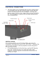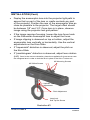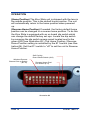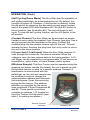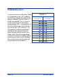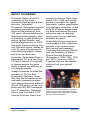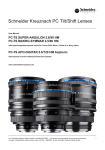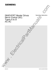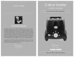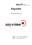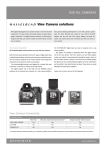
1
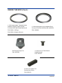
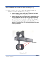
KINO SLIDE U S ER MAN UAL INTENTIONALLY LEFT BLANK Page 2 D101011 REV.A TABLE OF CONTENTS Welcome Page 3 Inside the box Page 4 Required Tools Page 6 Attachment of Lens to Kino Slide Unit Page 6 Electrical Connections Page 8 Installation Page 8 Operation Page 10 About Schneider Page 13 WELCOME Congratulations on your purchase of a Schneider Optics, Inc. Kino Slide anamorphic lens deployment unit. This system is composed of the finest mechanical components available. The mechanical assemblies within the Kino Slide lens mover are designed for the demanding duty cycle of a professional screening room. Installation by a qualified professional is recommended for best results. D101011 REV.A Page 3 INSIDE THE BOX NOTE: A Cine-Digitar Anamorphic lens is required to use the Kino Slide and must be purchased separately. Kino Slide (Lens shown for reference only) Power Supply (12-volt output, 50-60 Hz, 110-240-volt input) P/N: 027153 P/N: 9010-0012 Power Cord 3 Types Type US P/N: 9010-0042 Type EU P/N: 9010-0043 12-Volt Trigger Cable (3.5mm Jack, 3 meter length, Male-Male) P/N: 9010-0046 Type UK P/N: 9010-0044 2 Position Connector Terminal Block P/N: 050383 Page 4 Female to Female RS-232 to RJ45 Modular Adapter P/N: 027281 D101011 REV.A INSIDE THE BOX (Cont.) 1.33X Anamorphic Threaded Lens Adapter Ring W/ Nylon Screw 1.33X Anamorphic Lens Adapter Ring For lens P/N: I001.00345.02.00.35 For lens P/N: 54-047079 & 54-1055212 P/N: 026911 (Ring) P/N: 026896 P/N: 050316 (Nylon Screw) 4– M3 X 6 mm Flat Socket Head Screws RF Remote Key Fob P/N: 027332 P/N: 050157 10-32 X 1/2 Nylon Tip Socket Set Screw P/N: 050176 D101011 REV.A Page 5 REQUIRED TOOLS 1. 2mm Hex Wrench 2. 4mm Hex Wrench 3. 1/8” Hex Wrench 4. 3/32” Hex Wrench ATTACHMENT OF LENS TO KINO SLIDE UNIT There are two different methods of attaching the 1.33X anamorphic lens to the Kino-Torsion unit depending on the lens version being utilized. 1. Method 1 (Threaded lens P/N: I001.00345.02.0035 with P/N: 026911 Adapter Ring) Page 6 Attach the supplied threaded adapter ring on to the 1.33X anamorphic lens. Once ring is threaded on to lens, place the supplied nylon set screw onto the threaded adapter ring in order to lock the ring on to the lens. Attach lens to the Kino-Slide unit by threading lens to the octagonal arm of the unit until lens bottoms out. Rotate lens backwards until the flat sides of the inner bezel are vertical see Illustration #1. This is a temporary rough alignment method. See section “OPERATION” for fine adjustment and lens locking methods. D101011 REV.A ATTACHMENT OF LENS TO KINO SLIDE (Cont.) 2. Method 2 (Non thread lens P/N: 54-047079 & P/N: 541055212 with P/N: 026896 Adapter Ring) Attach adapter ring using the 4 supplied flat head screws to 1.33X anamorphic lens. Attach lens to the Kino-Slide unit by threading lens to the octagonal arm of the unit until lens bottoms out. Rotate lens backwards until the flat sides of the inner bezel are vertical see Illustration #1. This is a temporary rough alignment method. See section “OPERATION” for fine adjustment and lens locking methods. Inner Bezel Illustration #1 D101011 REV.A Page 7 ELECTRICAL CONNECTIONS 1. The Kino Slide unit, is supplied with a power supply which is compatible with US, UK, and EU power cords. Use the power cord best suited for the installation. Connect the power supply into the power input of the unit per Illustration #2. Once plugged in a green LED will light indicating the unit is powered up. Power Input Contact Closure 3.5 mm 12 Volt Trigger Power LED Dip Switch Access Panel RJ45 Input Illustration #2 INSTALLATION It is recommended to mount the Kino Slide unit using the Schneider Universal Kino mount P/N: 54-018742. However the unit can be mounted to various projector mounts using the 2 M5 mounting screws. If focusing projector for the first time, use the RF Remote Key Fob to take the lens out of the light path of the projector. Follow projector manufacturer instructions for setting up image. Page 8 D101011 REV.A INSTALLATION (Cont.) Deploy the anamorphic lens into the projector light path to assure that no part of the lens or cradle contacts any part of the projector. Position the rear of the anamorphic lens as close as possible to the projector. The target offset should be between 1/8” and 1/4”. Once lens is in place, observe image using the projector test grid pattern. If the image requires focusing, loosen the lens focus knob on the Schneider Anamorphic lens to adjust the focus. If image clipping is observed on top or bottom, adjust the anamorphic lens vertically or horizontally. Use the vertical adjustments on the Kino-Slide If “trapezoidal” distortion is observed, adjust the pitch on the Kino-Slide. If “parallelogram” distortion is observed, adjust lens rotation (roll). Once in the correct orientation, place the supplied soft tip set screw onto the octagonal arm in order to lock the lens in place to the Kino-Torsion unit. M5 Mounting Screws M5 Offset Screws Vertical/ Yaw Adjustment Pitch Adjustment Lens Lock Soft Tip Set Screw Illustration #3 D101011 REV.A Page 9 OPERATION (Home Position) The Kino Slide unit is shipped with the lens in the middle position. This is the default home position. The unit will automatically return to the home position when powered up. (Reverse Home Position) If needed, the factory default home position can be changed to a reverse home position. To do this the Kino Slide is equipped with an on board dip switch which can change the default factory set ups. Locate the dip switch by removing the dip switch access panel located next to the green LED (see Illustration #2.) The Home Position / Reverse Home Position setting is controlled by the #11 switch (see Illustration #4). Set the #11 switch to “off” to set the unit to Reverse Home Position. Self Cycling Demo Mode Switch (#12) Wireless Remote Channel Set up Switch (#1-10) Reverse Home Position Switch (#11) Illustration #4 Page 10 D101011 REV.A OPERATION (Cont.) (Self Cycling Demo Mode) The Kino Slide has the capability of self cycling indefinitely as a demonstration tool. By default, this function is turned off. However, if this function is desired, locate the dip switch by removing the dip switch access panel located next to the green LED (see Illustration #2.) Set the #12 switch to the on position (see Illustration #4.) The unit will begin to self cycle. To stop the self cycling function, set the #12 switch to the off position. (Contact Closure) The Kino Slide can be actuated via simple contact closure using the supplied 2 pin Phoenix type plug. Use a wire to connect the two terminals on the plug. Connect the modified plug into the contact closure input of the unit. This will actuate the lens. Remove the plug from the unit in order to return the unit to the home position. (3.5 mm Jack 12 volt input) When the Kino Slide receives 12 volts through this connector, the lens is actuated. When the voltage is zero, the lens returns back to the home position. A 12volt trigger can be supplied by a programmable 12-volt source on the projector, video scaler, or home theater control system. (Wireless Remote) The Kino-Torsion can be operated using the supplied one button remote. By default, the unit is paired up with the wireless remote to work on a specific address. However if interference is encountered with the default set up, the unit and remote may be modified in order to change the communication address and eliminate the interference. Open the remote by prying the two halves. The address definition is controlled by the circuit lines numbered 0-9 per Illustrations #4 and #5. These paired circuit lines correlate to switches 1-10 located on the Kino-Torsion Unit dip switch (see table 1 for pairing correlation.) Remote Channel Definition D101011 REV.A Illustration #5 Page 11 OPERATION (Cont.) A severed trace on the Key FOB corresponds to an “off” position on the Kino Scale dip switch. By factory default, the unit and remote are paired 1-2 (i.e. the remote circuit line #1 has been severed and this corresponds to the Kino Slide dip switch #2 being set to the “off” position.) To change to a different address switch off the desired switch from the dip switch on the unit. Next, sever the corresponding remote circuit line creating a discontinuity in that circuit number. Once done the remote and unit will be paired once again. Page 12 TABLE 1 Remote Kino-Torsion Circuit Line # Dip Switch # 0 1 1 2 2 3 3 4 4 5 5 6 6 7 7 8 8 9 9 10 D101011 REV.A ABOUT SCHNEIDER Schneider Optics is the U.S. subsidiary of the worldrenowned German optical manufacturer, SchneiderKreuznach. Schneider has been producing the highest quality optics on the market for over 100 years, offering solutions for large-format photography, photo enlarging, motion picture projection, optical filtration, and industrial applications. In 2000, Schneider Optics acquired Century Precision Optics, adding its over 50 years of experience in manufacturing superior attachments for film and video. Schneider Optics has offices in Hauppauge, NY and Van Nuys, CA and a network of hundreds of dealers around the globe, ready to assist you with any of your imaging needs. Joseph Schneider founded the company in 1913 in Bad Kreuznach, Germany. Since that time the Schneider factory has been constantly modernized, always remaining state-ofthe-art. The factory is fully compliant with ISO 9001 standards. Its U.S. subsidiary, Schneider Optics, was founded in 1972. Century Precision Optics first D101011 REV.A opened its doors in North Hollywood, CA in 1948, and quickly gained a reputation for expert lens repair, custom modification and intelligent innovation. In the early 80’s Century began creating what has become the most extensive array of ultra-high quality video lens accessories available anywhere. Separately the two companies were leaders in their respective spheres of the optical world— both having been awarded Technical Achievement Awards from the Academy of Motion Picture Arts and Sciences (Schneider in 2005, 2001, 1978 and 1976; Century in 1992). Together they are the ultimate solution to all your optical needs. Schneider Cinema Projection Lens technology has won four Technical Achievement Awards from the Academy of Motion Picture Arts and Sciences Page 13 7701 Haskell Ave. Van Nuys, CA 91406 818-766-3715 Fax: 818-505-9865 Email: [email protected] 285 Oser Ave. Hauppauge, NY 11788 631-761-5000 Fax: 631-761-5090 Email: [email protected]