1
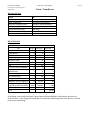
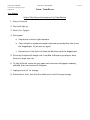
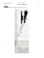
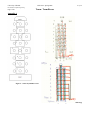
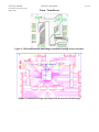
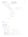
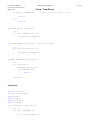
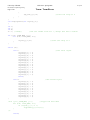
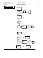
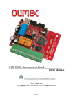
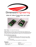
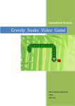
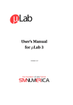
EEL 4924 Electrical Engineering Design
(Senior Design)
Final Report
21 April 2009
Project Title: Interactive Electronic Hopscotch Board
Team Name: Team Recess (Lose the Chalk)
Team Members:
Name: Karine Hoffman
Name: Joe Gillespie
Email: [email protected]
Email: [email protected]
Project Abstract:
Our project is the design of an interactive electronic hopscotch court that possesses the ability to change
the layout of the court based on user input. The board will change its layout by lighting up various
sections of the board in differing colors. The board will also detect whether the user landed on the
correct part of the court and provide a visual feedback. Furthermore, the court will also be able to handle
2 players and declare a winner when one person makes a mistake.
University of Florida
EEL 4924—Spring 2008
Electrical & Computer Engineering
Page 2/20
Team: Team Recess
Table of Contents
Item……..……..……..……..……..……..……..……..……..……..……..……..……..Page
Project Features/ Objectives.………..……..……..……..……..……..……..……..………..4
Analysis of Competition.……..……..……..……..……..……..……..……..………….......4
Technical Concept Selection ..……..……..……..……..……..……..……..……..………..4
Project Architecture …..……..……..……..……..……..……..……..……..…………........5
Division of Labor……..……..……..……..……..……..……..……..…………..……….....8
Bill of Materials
……..……..……..……..……..……..……..……..….....……..…..……8
User Manual ………………………………………………………………………………..9
Gantt Chart ……………………………………………………………………………….10
Appendix A………………………………………………………………………………. 11
Appendix B: Code…………………………………………………………………………14
21-Apr-09
University of Florida
EEL 4924—Spring 2008
Electrical & Computer Engineering
Page 3/20
Team: Team Recess
List of Figures and Tables
Item……..……..……..……..……..……..……..……..……..……..……..……..……..Page
Figure 1……..……..……..……..……..……..……..……..……..……..……..………….5
Figure 2……..……..……..……..……..……..……..……..……..……..……..………….6
Figure 3……..……..……..……..……..……..……..……..……..……..……..………….7
Figure 4…………………………………………………………………………………...10
Figure 5……..……..……..……..……..……..……..……..……..……..………...Appendix
Figure 6……..……..……..……..……..……..……..……..……..……..……..….Appendix
Figure 7……………………………………………………………………………Appendix
Figure 8……..……..……..……..……..……..……..……..……..……..……..….Appendix
Figure 9……..……..……..……..……..……..……..……..……..……..……..….Appendix
Figure 10……..……..……..……..……..……..……..……..……..……..……..…Appendix
Table 1..……..……..……..……..……..……..……..……..……..……..……..………….8
Table2..……..……..……..……..……..……..……..……..……..……..……..…………..8
21-Apr-09
University of Florida
EEL 4924—Spring 2008
21-Apr-09
Electrical & Computer Engineering
Page 4/20
Team: Team Recess
Project Features/ Objectives:
The main objective is to have the Hopscotch board react to players. In order to create a portable and
flexible game board, the pressure sensors and LEDs chosen are flexible and able to withstand bodily
forces.
We interface a series of pressure sensors with a microprocessor that maintain gameplay using LEDs as
visual control for the user. Multicolored LEDs enhance the board and provide direction for gameplay.
Basic hopscotch rules that our gameplay will follow are found in the User Manual in this document. The
microprocessor connects to an LCD and user interface buttons to select 1 or 2 players.
We would also like to be able to create an alterable game board allowing the user to play on different
hopscotch courts. This will be achieved by using LEDs to highlight the sensors and a random select on
start up to determine the court shape.
We are housing the electronic controls including the printed circuit boards, LCD and buttons in a
housing attached to the board through protected wires. This part does not fold up with the court mat.
Analysis of Competitor Products:
Interactive Digital Hopscotch can be categorized as an electronic toy. This game board simulates the
outdoor version by bringing it inside, making it safer and more contemporary. The rules of the game are
traditional but by integrating technology it increases the excitement and competition level.
Currently, other indoor mat versions of hopscotch exist but none are digital. Our concept will combine
the fun level of the foot piano from the movie “BIG” and the timeless game of hopscotch. Figure 2 and 3
help explain the rules we are using for the game along with the basic design of the board. The main
difference in rules from the standard hopscotch is that instead of a rock being thrown onto the board, we
are instead using a sensor at the beginning. When the sensor is hit, lights run up and down the board and
when hit again, they stop on a certain square. On the way to the finish, they must skip the square, and on
their way back, the player must hit the square with their hand.
Technical Concept Selection
Our original design has evolved over the course but still maintains the same objectives as far as
gameplay and performance.
We initially wanted the ability to individually select for each of the colors in each ring for total control
of the board. Our design included 160 pin CPLD and a 12 transistor arrays to power the LEDs from the
12V power supply. When our PCB design with this CPLD failed we immediately went into reevaluate
stage. We decided to try and optimize our design by using a smaller CPLD from our Digital Logic class,
less connections to the LEDs and less transistors to power these fewer connections. We created an array
type set up for the LEDs as indicated in the wiring diagram from figure 6 in the Appendix. We also
decided to go with separate red, green and blue led strands, instead of RGB, with 4 LEDs per strand,
three colors per ring and 26 rings for the court.
University of Florida
EEL 4924—Spring 2008
21-Apr-09
Electrical & Computer Engineering
Page 5/20
Team: Team Recess
This led to many more complex challenges because the individual ability to select is no longer, we could
not light up individual squares of the hopscotch court but instead need to use a raster scan concept to
create the illusion that the court is illuminated to the user.
The force sensitive resistors (FSR) design of our game is mostly intact, with our 32: 1 analog mux
selecting and scanning the 26 FSRs in the court and relaying this information to the Atmega32 ADC
port. We overcame one challenge of the least significant bit of the analog mux not toggling which makes
our 32:1 mux act as a 16:1. We developed the wiring from figure 6 for the FSRs to create fewer
connections and utilize the analog mux.
Our mat design consists of two foam mats adhered in the middle with spray adhesive, wrapped in two
slip resistant, water proof, translucent tarps. It is entirely foldable able to be carried by one person. The
electronic housing protects the PCBs and LCD from user damage.
Project Architecture
High level map of concepts in hopscotch design and overlall layout for gameplay. Please see appendix
for complete PCB layouts and connectivity between Atmega32 and CPLD board designs.
Figure 1 – High Level Diagram
University of Florida
EEL 4924—Spring 2008
Electrical & Computer Engineering
Page 6/20
Team: Team Recess
Figure 2. Detailed Overview of design connections
21-Apr-09
University of Florida
EEL 4924—Spring 2008
21-Apr-09
Electrical & Computer Engineering
Page 7/20
Team: Team Recess
Figure 3 Game Rules
University of Florida
EEL 4924—Spring 2008
21-Apr-09
Electrical & Computer Engineering
Page 8/20
Team: Team Recess
Division of Labor
Karine Hopscotch/Atmel/LCD Research Order Components Gameplay conceptualization Wiring (LED rings, FSRs) PCB functionality testing Game Mat material/design Documentation and Presentation Joe Force Sensor/ LED Research Preliminary Circuit Design Gameplay code development Test/Debug coding PCB design Test/Validation Presentation Table 1
Bill of Materials
Prototype Cost Objectives Part Unit(s) Cost/Unit Total Cost Force Sensor 28 7.88
228.51
Atmel MicroP 1 0
0
CPLD160 pin 2 25, 41
66
LEDs(104 per color) 312 .40
124.8
CPLD from 3701 1 0
0
PCB 1 78
100
LCD 1 20
20
Transistor array (ULN2003A) 12 0
0
Analog Mux (ADG732bsuz) 1 0
0
15V power supply 1 13
13
12 V power supply 1 25
25
Tubing 70ft .35
24.5
Mat(foam*2,tarp*2,edging*2) 6 14;7;12
66
Wiring (wire wrap:195 ft, 500ft Variable
100
rings:200 ft cable, FSRs:100ft) Misc(tape, glue etc) # #
150
Total 917.81
Table 2
Prototyping costs include extra parts, unused parts and unused boards which greatly increased our
incurred costs. As our design developed and we reached our final design these costs decrease to match
parts used in final design.
University of Florida
EEL 4924—Spring 2008
21-Apr-09
Electrical & Computer Engineering
Team: Team Recess
Page 9/20
User Manual
How to Play Interactive Hopscotch by Team Recess:
1. Plug in to turn on
2. Court will light up
3. Select 1 or 2 player
4. Start game:
a. Step on start to start light sequence
b. Stop red light on a hopscotch square that was previously blue: this is now
the skipped spot. If you miss try again!
c. Hop on board from Start to Home and back but avoid the skipped spot
5. Correctly hit spots will change color from Blue to Green as you step on them.
Incorrect steps turn red.
6. To play different courts win your game and a new court will appear randomly
selected from courts stored in the game.
7. Unplug to turn off for storage.
8. Folds sides in first, then fold the rolled court in half for easy storage.
University of Florida
EEL 4924—Spring 2008
Electrical & Computer Engineering
Page 10/20
Team: Team Recess
Gantt Chart
Updated Gantt chart includes light blue extensions to processes.
Figure 4. Gantt chart
21-Apr-09
University of Florida
EEL 4924—Spring 2008
21-Apr-09
Electrical & Computer Engineering
Team: Team Recess
Page 11/20
Appendix A
Figure 5 – Sensor layout/Basic court
Figure 6 wiring for FSRs and LED rings
University of Florida
EEL 4924—Spring 2008
21-Apr-09
Electrical & Computer Engineering
Page 12/20
Team: Team Recess
Figure 7. Quartus Diagram
Figure 8. PCB for Atmega32 and ADG732bsuz design. Headers attach CPLD to this board.
University of Florida
EEL 4924—Spring 2008
Electrical & Computer Engineering
Page 13/20
Team: Team Recess
Figure 9. CPLD board used in Final Design, Attached to Atmega board via headers
Figure 10. Initial PCB design with 160 pin CPLD not used in Final Design
21-Apr-09
University of Florida
EEL 4924—Spring 2008
21-Apr-09
Electrical & Computer Engineering
Page 14/20
Team: Team Recess
Appendix B: Code
led_toggle_16.h
#include <avr/io.h>
#include <util/delay.h>
#define LED_PORT PORTC // This is where the pins connecting to the CPLD will be
#define LED_DDR
DDRC // This is where the pins connecting to the CPLD will be
#define CLK_SET 0b10000000 // By "or"ing the Port plus this will set the clock bit
high.
#define CLK_CLEAR 0b01111111 // By "and"ing the Port plus this will clear the clock
and leave the others
#define MASK1
0b00000001
#define CLEAR_BIT 0b00010011
/******************
***This Toggles the Row
******************/
void ToggleRow(int led_num)
{
LED_PORT = led_num;
LED_PORT = (LED_PORT | CLK_SET);
}
/******************
***This will activate a certain column
*******************/
void SetCol(int led_num)
{
LED_PORT = (led_num+10);
}
void SetRowCol(int led_row, int led_col)
{
ToggleRow(led_row);
SetCol(led_col);
_delay_us(220);
ToggleRow(led_row);
}
/************
***Sends a Clear Command
************/
void ClearAll()
{
LED_PORT = 0x1F;
}
/*********************************
***This function rasters the court
***for a specified period of time
*********************************/
University of Florida
EEL 4924—Spring 2008
21-Apr-09
Electrical & Computer Engineering
Team: Team Recess
Page 15/20
void ShowCourt(int length, int rgb_tab[10][3])
{
int f, i, j, k, val;
for (f=0;f<length;f++)
{
for (i=0;i<10;i++)
{
ToggleRow(i+1);
//Set each row separately
for (j=0;j<3;j++)
//Go column by column
{
val=rgb_tab[i][j];
//Check to see if it's 1, 2, or 3
if(val==1)
//1=blue
{
k = ((j*3)+1);
SetCol(k);
}
else if (val==2) //2=green
{
k = ((j*3)+2);
SetCol(k);
}
else if (val==3) //3=red
{
k = ((j*3)+3);
SetCol(k);
}
}
ToggleRow(i+1);
}
}
}
Scan.h
#include <util/delay.h>
#define
#define
#define
#define
TRUE 1
FALSE 0
THRESHOLD 900
NUM_FSR 3
#define FSR_PORT
#define FSR_DDR
PORTA
DDRA
int SCAN_FSR(int fsr_num)
{
int adc_val;
//Declare the ADC Storage Value
fsr_num = (fsr_num << 1);
fsr_num = fsr_num + 1;
//Multiply by two
//Add one
fsr_num = (fsr_num << 1);
// Shift the number to the right
FSR_DDR = 0b01111110;
//Set the DDR properly
FSR_PORT = 0;
//Clear the Port
_delay_us(500);
FSR_PORT = (FSR_PORT | fsr_num); //Set the select lines
_delay_us(500);
//Delay by a bit to make sure ADC works
adc_val = ADC_START(0); //Convert the ADC
University of Florida
EEL 4924—Spring 2008
Electrical & Computer Engineering
Team: Team Recess
Page 16/20
if (adc_val > THRESHOLD)
{
return 1;
}
else
return 0;
//Return 1 if above thresh, 0 else
}
void SCAN_ALL(int fsr_press[])
{
int i;
for (i=0; i<(NUM_FSR+1); i++)
{
fsr_press[i]=SCAN_FSR(i);
}
}
void SCAN_RANGE(int fsr_press[], int start, int end)
{
int i;
for (i=start; i<(end+1); i++)
{
fsr_press[i]=SCAN_FSR(i);
}
}
int WHAT_PRESSED(int rgb_tab[][3])
{
int i;
for (i=0;i<13;i++)
{
ShowCourt(20,rgb_tab);
if (SCAN_FSR(i)==1)
{
return i;
}
}
return 99;
}
Gamestart.h
#include <avr/io.h>
#include <util/delay.h>
#define
#define
#define
#define
TRUE 1
FALSE 0
ROW_MAX 10
COL_MAX 3
void ClearArray(int rgb_tab[][3])
{
int i, j;
for (j=0; j<ROW_MAX; j++)
{
for (i=0; i<COL_MAX; i++)
21-Apr-09
University of Florida
EEL 4924—Spring 2008
21-Apr-09
Electrical & Computer Engineering
Team: Team Recess
Page 17/20
{
rgb_tab[j][i]=0;
//Clear the array to 0
}
}
}
void DisplayCourt(int layout[][3])
{
int
int
int
k =
i;
j;
k;
1; //rand();
//Set the random value for i, change this max in stdlib
for (j=0; j<ROW_MAX; j++){
for (i=0; i<COL_MAX; i++){
layout[j][i]=0;
//Clear the array to 0
}
}
switch (k) {
case 1:
layout[0][1]
layout[1][1]
layout[2][0]
layout[2][2]
layout[3][1]
layout[4][0]
layout[4][2]
layout[5][0]
layout[5][2]
layout[6][1]
layout[7][1]
layout[8][0]
layout[8][2]
layout[9][1]
break;
case 2:
layout[0][2]
layout[1][2]
layout[2][2]
layout[3][2]
layout[4][2]
layout[5][2]
layout[6][2]
layout[7][2]
layout[8][2]
layout[9][2]
//The first layout
=
=
=
=
=
=
=
=
=
=
=
=
=
=
1;
1;
1;
1;
1;
1;
1;
1;
1;
1;
1;
1;
1;
1;
=
=
=
=
=
=
=
=
=
=
1;
1;
1;
1;
1;
1;
1;
1;
1;
1;
//The second layout
}
/*for (j=0; j<ROW_MAX; j++){
//Toggle the blue LEDs
for (i=0; i<COL_MAX; i++){
if (layout[j][i] == 1)
ToggleLED(j,((i*3)-1));
}
}*/
return;
University of Florida
EEL 4924—Spring 2008
21-Apr-09
Electrical & Computer Engineering
Page 18/20
Team: Team Recess
}
Gameplay.h
int SnakeRed(int rgb_tab[][3])
{
int i, j, k;
int l=0;
while(1)
{
for (i=0;i<10;i++)
//Check every row
{
for (j=0;j<3;j++)
//Check every column
{
k=rgb_tab[i][j]; //Store the value that was there
previously
rgb_tab[i][j]=3; //Set the new one to red
ShowCourt(300, rgb_tab);
//Show the court for awhile
l = SCAN_FSR(0); //Check to see if pressed
if (l==1)
//If it was, stop
{
if (k==1)
//If it was blue, return a 0
{
return 0;
//This says that you passed
}
else
//Otherwise, return a 1
{
return 1;
//This says you failed
}
}
rgb_tab[i][j]=k; //Set the table back to whatever
}
}
}
}
void LightShow(int rgb_tab[][3])
{
ClearArray(rgb_tab);
int k, i, j;
for (k=1; k<4; k++)
{
for (i=0;i<10;i++)
{
for(j=0;j<3;j++)
{
rgb_tab[i][j]=k;
}
ShowCourt((300-i*28),rgb_tab);
}
for (i=10;i>-1;i=i-1)
University of Florida
EEL 4924—Spring 2008
Electrical & Computer Engineering
Team: Team Recess
Page 19/20
{
for(j=0;j<3;j++)
{
rgb_tab[i][j]=0;
}
ShowCourt((300-i*28),rgb_tab);
}
}
}
21-Apr-09
University of Florida
EEL 4924—Spring 2008
21-Apr-09
Electrical & Computer Engineering
Page 20/20
Blue-Green Flowchart
Team: Team Recess
Register 1
Blue?
Turn
Red
Fail
Turn Green
[1] [0]
[1] [1]
Blue?
Pressed
?
Delay w/
court
Pressed
?
Fail
Turn Green
[1] [1]
Move on
[1] [2]
Blue?
Pressed
?
Turn Green
[1] [2]
Delay w/
court
Pressed
?
Move on
Fail