1
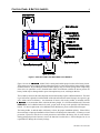
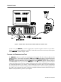
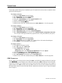
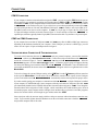
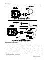
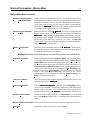
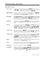
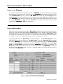
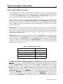
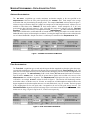
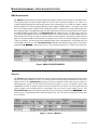
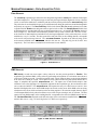
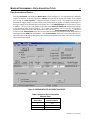
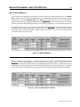
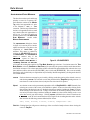
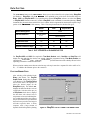
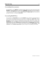
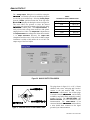
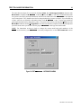
SILICON DESIGNS, INC
86(5
60$18$/
*/2**(5 MODEL 3320 REMOTE ACCELERATION ACQUISITION SYSTEM
TM
FEATURES
1, 2 or 3 Axis Remote Acceleration
4 Mega-Sample Non-Volatile Memory
Portable Battery Operation
-20 to +60°C Operation for System
(Wider Temp Range for Accelerometers)
Works with Model 2420 & 2010 Accelerometers
Simple PC Based Programming
Standard Ranges:
±2G, ±5G, ±10G, ±25G, ±50G, ±100G, ±200G
Other Ranges Available
115.2 kBaud Serial Data Link
Logs Various Data Types:
AC and DC Acceleration
AC and DC Peak Acceleration
Acceleration Peak Events
RMS Acceleration
AC Velocity
AC Peak Velocity
RMS Velocity
Temperature
Silicon Designs, Inc.1445 NW Mall Street, Issaquah, WA 98027-5344 Phone: 425-391-8329 FAX: 425-391-0446
WARNINGS
i
Improper installation of the batteries will damage this instrument. Install the
batteries according to the polarity markings inside the battery holder !
The battery inserts included with this device are designed to fit USA made
Duracell size D alkaline batteries ONLY and may not fit properly when other
brands of alkaline batteries are used. These inserts must fit snugly in their
proper positions. If the device is operated in severe vibration and/or shock
environments, without the inserts present, the battery holder may be
damaged or power interruption may occur, resulting in data loss.
Although the */2**(5 is built to sustain mechanical shock, it is a sensitive
instrument and care should be taken to not drop the device on hard surfaces.
During prolonged periods of non-use, remove the batteries from this device.
Silicon Designs, Inc. is not responsible for damage to this device due to
battery leakage.
Power to the */2**(5 should be turned OFF before connecting or
disconnecting the remote accelerometer(s).
OWNER'S RECORD
The model number is located on the cover and both the model and serial numbers are located on the inside wall
of the case adjacent to the control panel. Record the model and serial numbers in the spaces provided below.
Please refer to these numbers whenever you call upon Silicon Designs regarding your instrument.
*/2**(5TM
model No.
Serial No.
Website: www.silicondesigns.com
Silicon Designs, Inc.1445 NW Mall Street, Issaquah, WA 98027-5344 Phone: 425-391-8329 Fax: 425-391-0446
390-00002-05 Rev 10 Nov 2003
TABLE OF CONTENTS
ii
Before You Begin . . . . . . . . . . . . . . . . . . . . . . . . . . . . . . . . . . . . . . . . . . . . . . . . . . . . . . . . . . . . . . . . . . 1
Unpacking list . . . . . . . . . . . . . . . . . . . . . . . . . . . . . . . . . . . . . . . . . . . . . . . . . . . . . . . . . . . . . . . . 1
Typographical Conventions . . . . . . . . . . . . . . . . . . . . . . . . . . . . . . . . . . . . . . . . . . . . . . . . . . . . . . 1
Control Panel & Battery Inserts . . . . . . . . . . . . . . . . . . . . . . . . . . . . . . . . . . . . . . . . . . . . . . . . . . . . . . . 2
Connections . . . . . . . . . . . . . . . . . . . . . . . . . . . . . . . . . . . . . . . . . . . . . . . . . . . . . . . . . . . . . . . . . . . . . .
Choosing the Communications Port . . . . . . . . . . . . . . . . . . . . . . . . . . . . . . . . . . . . . . . . . . . . . . .
COM1 through COM4 Connections . . . . . . . . . . . . . . . . . . . . . . . . . . . . . . . . . . . . . . . . . . . . . . . .
Testing the Serial Connection &Troubleshooting . . . . . . . . . . . . . . . . . . . . . . . . . . . . . . . . . . . . . .
Accelerometer Connection(s) . . . . . . . . . . . . . . . . . . . . . . . . . . . . . . . . . . . . . . . . . . . . . . . . . . . . .
3
3
4
5
6
Software Installation . . . . . . . . . . . . . . . . . . . . . . . . . . . . . . . . . . . . . . . . . . . . . . . . . . . . . . . . . . . . . . . .
System Requirements . . . . . . . . . . . . . . . . . . . . . . . . . . . . . . . . . . . . . . . . . . . . . . . . . . . . . . . . . .
EasyPlot Installation . . . . . . . . . . . . . . . . . . . . . . . . . . . . . . . . . . . . . . . . . . . . . . . . . . . . . . . . . . .
*/2**(5TM 352*5$0 Software Installation . . . . . . . . . . . . . . . . . . . . . . . . . . . . . . . . . . . . . . . . . . . .
7
7
7
7
DC Calibration . . . . . . . . . . . . . . . . . . . . . . . . . . . . . . . . . . . . . . . . . . . . . . . . . . . . . . . . . . . . . . . . . . . . 8
Calibrate Mode . . . . . . . . . . . . . . . . . . . . . . . . . . . . . . . . . . . . . . . . . . . . . . . . . . . . . . . . . . . . . . . . 8
Continuous Update Mode . . . . . . . . . . . . . . . . . . . . . . . . . . . . . . . . . . . . . . . . . . . . . . . . . . . . . . . . 9
Mission Programming . . . . . . . . . . . . . . . . . . . . . . . . . . . . . . . . . . . . . . . . . . . . . . . . . . . . . . . . . . . . . .
Mission Menu Bar . . . . . . . . . . . . . . . . . . . . . . . . . . . . . . . . . . . . . . . . . . . . . . . . . . . . . . . . . . . . .
Mission Menu Controls . . . . . . . . . . . . . . . . . . . . . . . . . . . . . . . . . . . . . . . . . . . . . . . . . . . . . . . . .
Linking to the */2**(5 . . . . . . . . . . . . . . . . . . . . . . . . . . . . . . . . . . . . . . . . . . . . . . . . . . . . . .
Using the Mission Menu . . . . . . . . . . . . . . . . . . . . . . . . . . . . . . . . . . . . . . . . . . . . . . . . . . . . . . . .
Data Acquisition Types . . . . . . . . . . . . . . . . . . . . . . . . . . . . . . . . . . . . . . . . . . . . . . . . . . . . . . . . .
Average Acceleration . . . . . . . . . . . . . . . . . . . . . . . . . . . . . . . . . . . . . . . . . . . . . . . . . . . . .
Peak Acceleration . . . . . . . . . . . . . . . . . . . . . . . . . . . . . . . . . . . . . . . . . . . . . . . . . . . . . . .
RMS Acceleration . . . . . . . . . . . . . . . . . . . . . . . . . . . . . . . . . . . . . . . . . . . . . . . . . . . . . . .
Velocity . . . . . . . . . . . . . . . . . . . . . . . . . . . . . . . . . . . . . . . . . . . . . . . . . . . . . . . . . . . . . . .
Peak Velocity . . . . . . . . . . . . . . . . . . . . . . . . . . . . . . . . . . . . . . . . . . . . . . . . . . . . . . . . . . .
RMS Velocity . . . . . . . . . . . . . . . . . . . . . . . . . . . . . . . . . . . . . . . . . . . . . . . . . . . . . . . . . . .
Peak Acceleration Events . . . . . . . . . . . . . . . . . . . . . . . . . . . . . . . . . . . . . . . . . . . . . . . . .
Multi Step Missions . . . . . . . . . . . . . . . . . . . . . . . . . . . . . . . . . . . . . . . . . . . . . . . . . . . . . . . . . . . .
Temperature . . . . . . . . . . . . . . . . . . . . . . . . . . . . . . . . . . . . . . . . . . . . . . . . . . . . . . . . . . . . . . . . .
10
10
12
14
14
16
16
16
17
17
18
18
19
20
21
Running Missions . . . . . . . . . . . . . . . . . . . . . . . . . . . . . . . . . . . . . . . . . . . . . . . . . . . . . . . . . . . . . . . . .
Time Mode, Relative . . . . . . . . . . . . . . . . . . . . . . . . . . . . . . . . . . . . . . . . . . . . . . . . . . . . . . . . . . .
Time Mode, Absolute . . . . . . . . . . . . . . . . . . . . . . . . . . . . . . . . . . . . . . . . . . . . . . . . . . . . . . . . . .
Battery Life Considerations . . . . . . . . . . . . . . . . . . . . . . . . . . . . . . . . . . . . . . . . . . . . . . . . . . . . . .
22
22
23
23
Data Upload . . . . . . . . . . . . . . . . . . . . . . . . . . . . . . . . . . . . . . . . . . . . . . . . . . . . . . . . . . . . . . . . . . . . . 24
Standard Missions . . . . . . . . . . . . . . . . . . . . . . . . . . . . . . . . . . . . . . . . . . . . . . . . . . . . . . . . . . . . 24
Acceleration Event Missions . . . . . . . . . . . . . . . . . . . . . . . . . . . . . . . . . . . . . . . . . . . . . . . . . . . . . 25
Data Plotting . . . . . . . . . . . . . . . . . . . . . . . . . . . . . . . . . . . . . . . . . . . . . . . . . . . . . . . . . . . . . . . . . . . . . 26
Plotting Binary Files . . . . . . . . . . . . . . . . . . . . . . . . . . . . . . . . . . . . . . . . . . . . . . . . . . . . . . . . . . . 26
Plotting EasyPlot ASCII Files . . . . . . . . . . . . . . . . . . . . . . . . . . . . . . . . . . . . . . . . . . . . . . . . . . . . 27
Analog Output . . . . . . . . . . . . . . . . . . . . . . . . . . . . . . . . . . . . . . . . . . . . . . . . . . . . . . . . . . . . . . . . . . . . 28
Edit
2**(5
*/
Information . . . . . . . . . . . . . . . . . . . . . . . . . . . . . . . . . . . . . . . . . . . . . . . . . . . . . . . . 29
Specifications . . . . . . . . . . . . . . . . . . . . . . . . . . . . . . . . . . . . . . . . . . . . . . . . . . . . . . . . . . . . . . . . . . . . 30
Case dimensions . . . . . . . . . . . . . . . . . . . . . . . . . . . . . . . . . . . . . . . . . . . . . . . . . . . . . . . . . . . . . . . . . 31
390-00002-05 Rev 10 Nov 2003
BEFORE YOU BEGIN
1
Before you can use your */2**(5TM , you must first install the */2**(5 352*5$0 software. This
program has been verified to run under Windows 95, 98, NT4.0, 2000 and XP. If you have purchased the
optional EasyPlot * software, it should be installed prior to installation of the */2**(5 352*5$0. Unless
otherwise noted, this manual uses Windows 98 instructions and illustrations.
UNPACKING LIST
Please check that the following accessories are in the carton with your unit:
RS-232 Serial Cable (with 9 pin D-Subminiature connectors on each end)
RS-232 Null Modem Adapter (converts 9 pin D-Subminiature to 25 pin)
AC Power Adapter (115V to 9VDC @ 500 mA)
Male Mini Stereo Plug (3.5mm tip diameter for D/A output jack)
Female DC Power Plug (5.5mm outside, 2.1mm inside)
Case Mounting Screws (#8-32 x 1 machine screw) quantity 2
Battery Insert Set (two inside the */2**(5 plus alternate sizes)
DB9 Male to DB9 Female Flat Cable (to extend Accelerometer Connection)
*/2**(5 USER’S MANUAL Diskette, 3.5" floppy
*/2**(5 352*5$0 Diskette, 3.5" floppy
The following software item is optional and is included with your unit only if ordered:
EasyPlot* for Windows, version 4.04 (User Manual and 3.5" floppy disk)
* EasyPlot is a trademark of Spiral Software, 7909 Charleston Ct, Bethesda, MD 20817
TYPOGRAPHICAL CONVENTIONS
Bold type
Menu titles, menu button names, menu field entries and hardware device
names are shown in boldface type.
<return>
Keystrokes are boldface and enclosed in "<" and ">" symbols.
Monospaced Font
Examples of filenames and file text are shown in a monospaced font.
[date/time]
Dates and times are listed between square brackets [ ].
390-00002-05 Rev 10 Nov 2003
CONTROL PANEL & BATTERY INSERTS
2
Figure 1: CONTROL PANEL FEATURES & BATTERY INSERTS
Figure 1 shows the */2**(5 Model 3320's control panel and the proper location of the battery inserts.
These inserts prevent the batteries from breaking their positive connections with the battery holder during
mechanical shock. By straddling the battery holder springs, they prevent the springs from compressing.
If the device is operated in severe vibration and/or shock environments, without the inserts present, the
battery holder may be damaged and/or power interruption may occur, resulting in data loss.
The two battery inserts are the same shape but each location usually requires a different thickness. The short
leg of each insert is placed toward the middle of the unit and each insert must fit snug in its respective gap
at the minus end of each battery. An assortment of inserts, with varying widths, is included with the
*/2**(5 to accommodate minor variations in battery length. It is recommended that only USA made
DURACELL size D alkaline batteries be used; proper insert fit may not be possible with other battery
brands. For insert replacement or for additional insert thicknesses, please contact Silicon Designs.
The battery holder is marked under each battery to show the proper installation polarity. Please follow
these markings as improper installation of the batteries will damage this instrument. No battery reversal
protection is present in this device as such protection would shorten the battery life for each mission.
During prolonged periods of non-use, remove the batteries from this device. Silicon Designs, Inc. is not
responsible for damage due to battery leakage.
390-00002-05 Rev 10 Nov 2003
CONNECTIONS
3
Figure 2: SERIAL DATA CABLE and AC POWER ADAPTER CONNECTIONS
In order to use your */2**(5, it must be programmed for the data acquisition "mission" of your choice.
Mission programming is accomplished over an RS-232 serial cable connected between your personal computer
and the */2**(5 as shown in figure 2 above.
CHOOSING THE COMMUNICATIONS PORT
The */2**(5 software is capable of communication with any of the first four serial port addresses that
Windows supports. These ports are designated as COM1 through COM4 and the choice of which COM port the
*/2**(5 software uses is made during software installation (see SOFTWARE INSTALLATION). It can also be
changed after software installation by selecting COM Port from the Preferences pull down menu bar at the top
of the Mission Menu. Before you connect the */2**(5’s serial cable to your computer, you must first locate
an unused serial port on the rear of your computer and this port must be capable of the highest data transmission
rate supported by Windows of 115.2 kbaud. For this transmission speed, the UART (Universal Asynchronous
Receiver Transmitter) IC used in the serial port you choose should be either a 16550 or 16550A type; older 8250
type UART’s may not operate fast enough. Consult your computer's hardware manual to determine the type of
hardware serial ports that are present in your computer.
390-00002-05 Rev 10 Nov 2003
CONNECTIONS
4
To determine which COM ports are installed on your PC and the device drivers that are attached to them,
perform the following steps:
For Windows 95/98 PCs:
1. Double click My Computer from the Desktop.
2. In the My Computer menu click Control Panel.
3. In the Control Panel menu click System.
4. Click on the Device Manager tab on the System Properties menu.
5. Enable the View Devices by Type radio button.
6. Double click on Ports (COM & LPT).
7. Double click on each of the communications ports COM1, COM2, etc to view their properties.
For Windows 2000 PCs:
1. Double click My Computer from the Desktop.
2. In the My Computer menu click Control Panel.
3. In the Control Panel menu click Administrative Tools.
4. In the Administrative Tools menu click Computer Management.
5. In the Computer Management tree structure select System Information, Components, Ports, Serial.
The view pane on the right will show the properties for the serial ports enabled in your system.
For Windows NT 4.0 PCs:
1. Double click My Computer from the Desktop.
2. In the My Computer menu click Control Panel.
3. In the Control Panel menu click Ports. The resulting list box will contain all enabled ports.
4. Click Settings to view the properties for each port.
For Windows XP PC’s:
1. Click start on the Windows task bar.
2. In the start menu click Control Panel.
3. If your Control Panel menu is set to:
Classic View mode, click System.
Category View mode, click Performance and Maintenance, then click System.
4. Click on the Hardware tab on the System Properties menu.
5. Click the Device Manager button on the System Properties menu.
6. In the Device Manager menu double click on Ports (COM & LPT).
7. Double click on each of the communications ports COM1, COM2, etc to view their properties.
COM1 CONNECTION
If your computer has a serial type mouse connected to COM1, you should select another serial port for connection
of the */2**(5. If your computer uses a USB or PS2 type mouse, COM1 will likely be open and useable.
It may also be useable if your computer has an "In-Port" type mouse that connects directly to your computer's
graphics display card. COM1 is usually a male 9-pin (DB9) connector on the rear of the computer and will accept
the female 9-pin connector on the serial cable directly, without the need for the 25-pin to 9-pin serial adapter
shown in figure 2.
390-00002-05 Rev 10 Nov 2003
CONNECTIONS
5
COM 2 CONNECTION
If your computer contains an internal modem assigned to COM2, you can free up the COM2 hardware port on
the rear panel of your computer by assigning your internal modem to COM3 or COM4. The */2**(5 can then
be installed on COM2. If your computer has an external modem connected to COM2 you can alternately connect
the */2**(5 or the modem to the port. If you wish to leave your modem permanently connected to COM2,
you will need to purchase an I/O card with additional COM ports. COM2 is usually a male 9-pin (DB9) or 25pin (DB25) connector on the rear of the computer. If COM2 is a 25-pin type, it requires the use of the 25-pin
to 9-pin serial adapter with the serial cable shown in figure 2. Do not attempt to connect the */2**(5 to
a parallel port, which are typically female 25-pin (DB25) connectors that look very similar to a 25-pin serial port.
COM3 OR COM4 CONNECTIONS
If your computer has more than 2 COM ports, COM3 and COM4 may either be DB9 or DB25 type connectors
depending on the hardware installed in your computer. If the COM port you choose is a DB25 type, you will
need to use the 9-pin to 25-pin serial adaptor shown in figure 2.
TESTING THE SERIAL CONNECTION & TROUBLESHOOTING
To test the serial connection between the */2**(5 and your personal computer, you must first install the
*/2**(5 software (see SOFTWARE INSTALLATION). Connect the serial port cable between the */2**(5
and the PC as shown in Figure 2. Turn the */2**(5 ON then run the */2**(5 352*5$0. When the
Mission Menu appears, click the LINK TO G-Logger button. A Windows progress gauge will appear showing
the status of the linking process and the ARM LED on the */2**(5 will illuminate. Once the link has been
successfully established, the current status of the */2**(5 will appear in the lower right-hand corner of the
Mission Menu.
To check or change the current COM port setting, select COM Port from the Preferences pull down menu bar
at the top of the Mission Menu. You do not have to set the baud rate, number of bits or parity for the COM port
you have selected because the */2**(5 352*5$0 automatically sets the selected port to the proper values.
If you have trouble getting your computer to communicate with the */2**(5, verify the COM port is enabled
in your computer’s CMOS RAM setup. Some computers, with only two hardware COM ports, have their COM2
port intentionally disabled in the CMOS RAM and their internal modem assigned to COM2. Even though an
internal modem can be assigned to COM3 or higher, which would allow the COM2 hardware port to be used
for another purpose, many computer makers configure their machines this way because some older programs
that use the modem will not work through any port address other than COM2.
Some serial port cables do not mate snugly with the serial port connector and an intermittent connection may
result. To prevent this, tighten down the thumbscrews on the serial cable connectors at both the */2**(5
and personal computer ends of the cable.
390-00002-05 Rev 10 Nov 2003
CONNECTIONS
6
ACCELEROMETER CONNECTION(S)
Turn the */2**(5 OFF before connecting or disconnecting the remote accelerometer(s). Each time you
change accelerometer(s), you must reconfigure the settings via the Edit G-Logger Information menu and recalibrate the system via the DC Calibration menu. Two different accelerometer configurations are possible with
the Model 3320. Figure 2A shows a Model 2420 digital tri-axial accelerometer directly connected to the DB9
jack on the side of the */2**(5. Figure 2B shows how up to three individual, single axis, Model 2010 digital
accelerometers can be connected to the DB9 jack on the side of the */2**(5 via a Model 3901 cable adapter.
To ensure reliable connections, tighten the jack screws on the Model 2420 or 3901 DB9 plug where it mates to
the */2**(5’s side jack. For Model 2010s, make sure their Weathertight bayonet connectors have been
turned as far as they will go. The ten-foot long DB9 male to DB9 female flat cable (included with the 3320) may
be used to extend the connection length between the 3320's DB9 jack and the DB9 plug on either the 2420 or
3901. For longer cable extension lengths, please contact Silicon Designs. Do not use an extension cable type
other than that supplied by Silicon Designs.
390-00002-05 Rev 10 Nov 2003
SOFTWARE INSTALLATION
7
SYSTEM REQUIREMENTS
Operating System . . . . . . . . . . . . . . .
Processor . . . . . . . . . . . . . . . . . . . . .
Serial Port . . . . . . . . . . . . . . . . . . . . .
Dynamic RAM . . . . . . . . . . . . . . . . .
Free Hard Disk Space . . . . . . . . . . . .
Windows 95, 98, NT4.0, 2000 or XP
486 or higher (Pentium recommended*)
16550 or 16550A UART (will not work with older 8250 UART)
16Mb RAM (32Mb recommended*)
40Mb free hard disk (100Mb recommended*)
* The recommended requirements are necessary for acceptable speed in the graphic display of data from
missions which use more than three quarters of the */2**(5’s flash memory. The EasyPlot
software will exhibit unacceptable delays if the recommended system requirements are not met.
EasyPlot INSTALLATION
If you purchased the optional EasyPlot software, it is recommended that you install it onto your PC first,
before installing the */2**(5 352*5$0. To install EasyPlot, follow the directions in the EasyPlot
manual. EasyPlot installs itself to a default directory on your PC and the */2**(5 352*5$0 expects
to find EasyPlot in that default directory. If you choose to install EasyPlot in a different directory, please
make note of it because the */2**(5 352*5$0 will request EasyPlot’s directory location during setup.
*/2**(5 352*5$0 SOFTWARE INSTALLATION
To install or upgrade the
*/
2**(5 352*5$0
on your hard disk,
1. Close all other applications that are currently running.
2. Insert the
*/
2**(5 352*5$0
disk into your computer’s floppy drive.
3. Click Start on the Windows task bar, then click Run...
4. Click Browse..., then browse to the floppy drive you placed the disk in.
5. Select the file G-LoggerXXX.EXE (where XXX is the software version number), then click OK.
6. Follow the on-screen instructions.
390-00002-05 Rev 10 Nov 2003
DC CALIBRATION
8
The DC Calibration menu, shown in figure 3A, has two modes, Calibrate and Continuous Update. In the
Calibrate mode, the */2**(5 can compensate for the bias error (zero-g offset) of each of its three
acceleration axes. In the Continuous Update mode, the */2**(5 displays the instantaneous acceleration
of each axis in real time. To reach the calibration menu, select DC Calibration from the Utilities pull down
menu bar at the top of the Mission Menu.
CALIBRATE MODE
Initial calibration was performed at the factory and a printout of these calibration results were included in your
shipment. For best long term accuracy, the calibration sequence should be periodically performed by the user.
Please note that the calibration is only valid for the accelerometer serial number(s) listed in the DC Calibration
menu. Each time an accelerometer is changed, its model and serial number must be set in the */RJJHU’s
memory by clicking the Edit Accel Configuration button (see figure 3B) and then a re-calibration must be
performed.
To perform calibration, first verify the accelerometer model and serial number information in the menu matches
the accelerometer(s) connected to the */2**(5. If they do not match, click the Edit Accel Configuration
button and enter the proper accelerometer data in the resulting pop-up menu (see figure 3B). Once the
accelerometer model and serial numbers are correct, click the DC Calibration menu’s Calibrate Mode radio
button. Then click the Start button which presents a series of simple instructions directing the operator to
place each connected accelerometer in both its positive and negative orientation.
The resulting Bias Correction
values are then calculated as the
average of their respective
uncorrected
+1g and
-1g
readings. Next, the operator is
given the option of replacing the
old Bias Correction values with
the new values. Acceleration
readings are taken for a period of
about five seconds for each of the
six orientations; it is very
important the accelerometers are
not moved during each of the six
sampling periods to achieve
accurate Bias Correction values.
Figure 3A: DC CALIBRATION MODE (Calibrate Menu)
390-00002-05 Rev 10 Nov 2003
DC CALIBRATION
9
CALIBRATE MODE (CONTINUED)
The Calculated Scale Factor is the difference between the
uncorrected +1g and -1g readings divided by two. The
+1g, -1g, Calculated Scale Factor and 0g Bias
(uncorrected) values are included for reference purposes.
They are displayed only after a calibration has just been
completed and the calibration menu remains open. Once the
DC Calibration menu has been closed, these values are no
longer displayed. It is suggested that whenever a recalibration is performed, the menu be printed for a
permanent record by clicking the Print button.
Figure 3B: EDIT ACCELEROMETER
CONFIGURATION
CONTINUOUS UPDATE MODE
The Continuous Update mode (see
figure 4) is useful for quickly showing
that the */2**(5 is functioning
properly and for the user to become
familiar with the sensitive directions of
the three axes. To enter this mode, click
the Continuous Update radio button,
then click Start. Real time acceleration
readings will appear in the Corrected
Current gForce boxes. Each Corrected
Current gForce reading is calculated as
the sum of the uncorrected reading plus
the Bias Correction value that was
previously stored for that particular axis.
Figure 4: DC CALIBRATION MENU (Continuous Update Mode)
390-00002-05 Rev 10 Nov 2003
MISSION PROGRAMMING - MISSION MENU
10
The Mission Menu, shown in figure 5, is the first menu displayed when the */2**(5 352*5$0 is
executed. This menu allows the operator to activate the communication link with the */2**(5, to program
missions, to download a mission to the */2**(5, to run missions and to upload and plot data from a
completed mission.
Figure 5: MISSION MENU
MISSION MENU BAR
File, Exit
Closes the mission menu dialog.
Utilities, DC Calibration
Allows the operator to perform a calibration of the DC offset for each of
the three accelerometers. This menu also displays real time acceleration
values to the screen. Please refer to the DC CALIBRATION section for
detailed instructions.
Utilities, Analog Output
Allows the output of real time analog acceleration values, from a
selected axis, to the D/A output jack on the */2**(5's control panel.
Please refer to the ANALOG OUTPUT section for detailed instructions.
Utilities, Edit G-Logger Information
Displays the */2**(5’s serial number. This values is factory set and
stored in the */2**(5's flash memory. This menu allows the value
to be corrected should it ever become corrupted. Please refer to the
EDIT G-LOGGER INFORMATION section for detailed instructions.
390-00002-05 Rev 10 Nov 2003
MISSION PROGRAMMING - MISSION MENU
11
MISSION MENU BAR (CONTINUED)
Utilities, G-Logger Diagnostics,
Flash Memory Report
Displays the status of the Flash memory array. The number and addresses of
any bad pages or bad blocks in the array are reported in this menu. A few
bad pages are common, even on a new unit. Bad blocks are less common.
As the Flash memory array ages, bad pages & blocks are automatically
detected by the */2**(5 and marked as not useable, much the same way
as personal computer marks bad sectors on its hard drive.
Utilities, G-Logger Diagnostics,
Self Test
Initiates a self test to verify the */2**(5 is in proper working order and
displays the test results. The I/O Test checks the internal I/O within the
*/2**(5. Short Version and Long Version Flash memory array test
options are provided; the short version tests one location on every Flash page
and the long version tests every location on every page. The DAC Test
outputs a 4.095V peak to peak, 320 Hz continuous sine wave to the D/A jack
on the */2**(5’s control panel.
Utilities, G-Logger Reset
Erases the system information stored in the */2**(5’s flash memory.
The unit’s serial number, model number and the table which keeps track of
the bad areas of flash memory will be lost.
WARNING! The Reset operation should only be invoked when problems occur with the device.
Preferences, File Format
This menu allows the selection of English or Metric units of measure for use
in the menus, data files and EasyPlot graphical display. Binary, ASCII or
EasyPlot ASCII can be selected as the preferred data file storage format. For
a description of these file formats and a guide for which one to choose, see
the DATA UPLOAD and DATA PLOTTING sections. This menu also allows the
selection of how time is to be stored and displayed. Date/Time Strings logs
both date and time and Time in Seconds omits date information. Dates are
stored in the format [month/day/year] and times in the format
[hh:mm:ss.ss]. The combination of using both Date/Time Strings and
Binary file format is not allowed.
Preferences, COM Port
Allows the selection of the computer port that will be used for RS-232 serial
communication with the */2**(5.
Preferences, Directories
Tells the */2**(5 352*5$0 where the optional EasyPlot software
resides on your computer. Note that the full directory path and program
filename must be specified. This menu also allows the selection of the
directory location where your */2**(5 mission data files will be stored.
Missions, Add to Favorites
Saves the mission currently displayed in the Mission Menu as a user-defined
name in the Missions drop down box. A maximum of ten missions may be
stored.
Missions, Remove from Favorites Allows for the removal of previously stored favorite missions one by one.
Help, About
Displays the software and firmware version numbers.
390-00002-05 Rev 10 Nov 2003
MISSION PROGRAMMING - MISSION MENU
12
MISSION MENU CONTROLS
LINK TO G-Logger
Establishes the communication link between the */2**(5 and your computer. If
the */2**(5 has just been powered up, there will be a delay of 5 to 15 seconds
while the mission handling program is downloaded to the */2**(5.
DOWNLOAD MISSION
Transmits the mission currently displayed in the Mission Menu to the */2**(5.
If the mission has incorrect entries, a message box will report any errors found. This
button appears only when Time Mode, Relative is selected.
START MISSION
The DOWNLOAD MISSION button changes to the START MISSION button when Time
Mode, Absolute is selected. The START MISSION button transmits the mission
currently displayed in the Mission Menu to the */2**(5 and starts the mission.
If the mission has incorrect entries, a message box will report any errors found.
UPLOAD DATA
Initiates the transfer of data from the */2**(5 to the PC after a mission has been
completed. The UPLOAD DATA button is only enabled if valid data is available for
upload.
PLOT DATA
Once data has been uploaded from the */2**(5, the PLOT DATA button initiates
the EasyPlot data graphing program. EasyPlot is a commercially available
software package that is recommended for use with the */2**(5 352*5$0.
EasyPlot "batch commands" are automatically included in uploaded files that are in
the Binary or EasyPlot ASCII format (selected via Preferences) to simplify plotting.
Time Mode, Relative
This time mode requires the */2**(5 to be turned off once a mission has been
downloaded. The mission will begin the next time the */2**(5 is powered up.
All times reported in the mission data file will be relative to the turn-on time.
Time Mode, Absolute
This time mode causes a mission to start at the date and time specified in Start Date
and Start Time. The mission is initiated by clicking the START MISSION button. For
the */2**(5 to keep proper absolute time, it must remain powered up. The
*/2**(5 must therefor be under battery power when the START MISSION button
is clicked, if battery power is to be used during the mission.
Start Date
Displays the date on which the mission currently being programmed will begin. This
field is only enabled if Time Mode, Absolute is selected.
Start Time
Displays the time at which the mission currently being programmed will begin. This
field displays 24 hour time and is only enabled if Time Mode, Absolute is selected.
G-Logger Serial#
Displays the serial number received from the
G-Logger Model#
Displays the model number received from the */2**(5. Both the model and serial
numbers are factory set into the */2**(5’s flash memory. The proper model and
g-level suffix must appear in this field or improper display of data may occur. If these
numbers are ever found to be in error, a G-Logger Reset should be performed.
*/
2**(5.
390-00002-05 Rev 10 Nov 2003
MISSION PROGRAMMING - MISSION MENU
13
MISSION MENU CONTROLS (CONTINUED)
Mission Tag
This field consists of the */2**(5's serial number, current date, and 24 hour
time, to ensure each tag is unique. The Mission Tag is the filename used to store
the collected data from the mission. The tag is continually updated according to the
PC’s clock until the DOWNLOAD MISSION or START MISSION button is selected.
Relative Start Time
Contains the relative starting time for each of the mission steps and is displayed in
the form [hhh:mm:ss.ss] where [hhh] is hours, [mm] is minutes and [ss.ss] is
seconds. This value is always zero for the first step and is automatically calculated
from the previous step entered, but can be modified by the operator. If "time gaps"
between mission steps are entered, sleep steps will automatically be inserted into the
mission. If Time Mode, Relative is selected, Relative Start Time corresponds to
when the */2**(5 will eventually be powered up with a new mission pending.
If Time Mode, Absolute is selected, Relative Start Time corresponds to the mission
Start Time and Start Date.
Duration
Allows the user to specify the length of time for the corresponding mission step and
is displayed in the form [hhh:mm:ss.ss] where [hhh] is hours, [mm] is minutes
and [ss.ss] is seconds. Decimal values (without any colon ':' characters) entered
into this field are interpreted as seconds. All entries to this field are converted
automatically to the full [hhh:mm:ss.ss] format.
Enable X Y Z
These check boxes allow data collection to be enabled or disabled on each of the
three acceleration axes. A checkmark signifies data will be gathered for that axis.
Acquisition Type
This drop down box contains the various acquisition types available, which are:
Sleep, Average Acceleration, Peak Acceleration, RMS Acceleration, Velocity,
Peak Velocity, RMS Velocity and Acceleration Events.
Accelerometer Clock
This box is for information purposes only and displays the accelerometer clock rate
that will be used for the Acquisition Type selected. The more compute intensive
acquisition types use the lower 500 kHz clock rate while the others use 1 MHz..
Samples/Second
Allows the user to specify the data acquisition rate in samples per second for the
current acquisition type. This value is fixed at 2000 samples/second for Peak
Velocity acquisitions and is user selectable for the other acquisition types.
Store Peak Every
This field is enabled only when the Peak Acceleration or Peak Velocity acquisition
type has been selected. Only the largest absolute magnitude samples that occur for
each of the enabled axes (within each peak sample period) are recorded.
Calculated Resolution
Displays the minimum step size that can be resolved, on each axis, for the
Acquisition Type selected. This field is automatically calculated based upon the
speed of the Accelerometer Clock and the number of Samples/Second.
Acceleration resolutions are displayed in mg (milli g-force) and velocity resolutions
are displayed in either in/s (inches/second) or cm/s (centimeters/second) depending
on the settings in Preferences, Units.
Sample Temperature Every Will take temperature samples throughout the mission at the rate selected by the
operator in the drop down box.
Clear
This button clears all mission specific fields in the menu.
390-00002-05 Rev 10 Nov 2003
MISSION PROGRAMMING - MISSION MENU
14
LINKING TO THE */2**(5
The communication link must be established between the */2**(5 and the PC before any tasks requiring
data transfer may be performed. First, connect the PC to the */2**(5 using the RS232 cable as discussed
in the CONNECTIONS section. Next, turn the */2**(5 ON, then click the Link To G-Logger button in
the Mission Menu. There will be a delay of 5 to 15 seconds while the mission handling program is downloaded
to the */2**(5. Once the link is established, the serial number, model number, mission tag and current
status of the */2**(5 are displayed on the Mission Menu. Successful establishment of the link is also
signified by the */2**(5's ARM LED illuminating.
USING THE MISSION MENU
Missions are entered and downloaded using the Mission Menu which has been designed to only allow input to
fields which require information based upon the Acquisition Type selected. All unnecessary fields are disabled
and in some cases the values will be calculated for you. Moving to each field in the Mission Menu can be
accomplished by positioning your mouse pointer over the desired control and clicking your left mouse button.
The <Tab> key may also be used and will step the cursor to the next field in the menu.
The initial conditions for the Mission Menu are shown in figure 6. The Relative Start Time is set to
[000:00:00.00] and cannot be changed. If Time Mode, Relative is selected, Relative Start Time corresponds
to when the */2**(5 will eventually be powered up with a new mission pending. If Time Mode, Absolute
is selected, Relative Start Time corresponds to the mission Start Time and Start Date. The fields G-Logger
Serial# and G-Logger Model# contain values sent from the */2**(5 when the link was established. The
Mission Tag provides automatic identification for each mission and consists of the */2**(5’s Serial#, date
and time to ensure each tag is unique. This tag is continually updated every minute until the mission is
downloaded to the */2**(5.
Figure 6: INITIAL CONDITIONS FOR MISSION MENU
390-00002-05 Rev 10 Nov 2003
MISSION PROGRAMMING - MISSION MENU
15
USING THE MISSION MENU (CONTINUED)
Initially, Duration is the only mission control which will accept input from the user. The remaining dialog fields
are enabled as input is required. Once a duration time has been entered, you may then enable/disable the desired
axes. If the selected Acquisition Type utilizes the Samples/Second and Store Peak Every fields, valid entries
must be made in these fields in order to proceed to the next mission step.
Each field requiring a time entry is of the form [hhh:mm:ss.ss] where [hhh] is hours, [mm] is minutes and
[ss.ss] is seconds. These fields, Relative Start Time, Duration, and Store Peak Every will automatically
convert your input to this format. For example, if you place your cursor in the Duration control, type [4:00],
and press <Tab>, the field entry will automatically display as [000:04:00.00]. Any unknown characters that
are input will be ignored.
Acquisition Type is a drop-down box that contains a preselected list of entries to choose from. Placing your
mouse pointer over the control and clicking your left mouse button will display the list of entries. To make a
selection, move your mouse pointer over the entry you wish to select and again click the left mouse button. The
entry selected should now be displayed in the control window. Alternatively, the arrow keys can be used to
scroll through the available choices.
Samples/Second requires user input for all acquisition types except Peak Velocity. This field is automatically
fixed at 2000 samples/second for Peak Velocity acquisition. The valid range of input values for Samples/Second
are shown in Table 1. The Samples/Second rate, the Accelerometer Clock rate and the full scale acceleration
of each axis determine the values displayed the Calculated Resolution field. Please note that maximum
resolution is achieved at a rate of 32 samples per second and resolution does not increase as the sample rate is
reduced below 32 samples per second.
Table 1: Acquisition Rate vs. Type
ACQUISITION TYPE
Samples/Sec RANGE
Acceleration, Peak Acceleration & Velocity
1 to 4000
Peak Velocity
fixed at 2000
RMS Acceleration & RMS Velocity
1 to 10
Acceleration Peak Events
16 to 4000
The Relative and Absolute radio buttons contained in the Time Mode group box affect when the acquisition
of mission data begins. If Time Mode, Relative is selected, the mission will start relative to when the
*/2**(5 power switch is turned on again after a mission has been downloaded and the unit was turned off.
Selecting Time Mode, Absolute enables the group box fields Start Date and Start Time and loads them with
the current date and time. These two fields represent the date and time the mission will begin once the START
MISSION button has been clicked. Start Date and Start Time are continually updated with the current time while
programming the mission unless they are set by the user to a future date and time. Missions programmed using
Time Mode, Absolute require that the */2**(5 power is not turned off once a mission has been started. For
example, if the */2**(5 is using external AC power when the START MISSION button is clicked, it must
remain connected to external AC power throughout the mission. If the */2**(5 is using internal battery
power when the START MISSION button is clicked, it may be moved to any location throughout the mission.
390-00002-05 Rev 10 Nov 2003
MISSION PROGRAMMING - DATA ACQUISITION TYPES
16
AVERAGE ACCELERATION
The Ave. Accel. acquisition type records continuous acceleration samples, at the rate specified in the
Samples/Second field, for the time period specified in the Duration field. Each sample is the average
acceleration that was present during the sample period. The example Ave. Accel. mission, shown in figure 7,
collects average acceleration values for 5 minutes at a sample rate of 1000 samples/second. All three axes are
enabled to collect data as the Enable X Y Z check marks indicate. In this example the X, Y & Z axis
accelerometers have full scale ranges of ±10g, ±25g and ±50g respectively which is why the Calculated
Resolution is different for each axis. The sample rate of 1000 Samples/Second provides a maximum theoretical
bandwidth of 500Hz and a useful bandwidth of around 200 Hz. Raising the sample rate would widen the
bandwidth at the expense of decreasing the resolution. Lowering the sample rate improves the resolution at the
cost of reduced bandwidth. Sample rates from 1 to 4000 may be entered into the Samples/Second field.
Figure 7: AVERAGE ACCELERATION MISSION
PEAK ACCELERATION
The Peak Accel. acquisition type records only the largest absolute magnitude acceleration value that occurs,
on each of the enabled axes, within the peak interval time period specified in the Store Peak Every field. The
peak value for each enabled axis may occur at different times during the peak interval and both magnitude and
polarity are reported. The Store Peak Every field is in the format [hhh:mm:ss.ss] and must be less than or
equal to half the Duration time. It must also be greater than or equal to 0.01 seconds or the inverse of the
Samples/Second rate, whichever is greater. The Samples/Second field requires the entry of a value between
1 and 4000. An example Pk. Accel. mission is shown in figure 8. This mission will continuously monitor
acceleration values, on all three axes, for 12 hours, at a sample rate of 4000 samples/second and will save the
largest magnitude acceleration samples that occur, on each enabled axis, every 0.1 seconds. The time reported
in the resulting data file for each peak value, corresponds to the end of each peak storage interval. The
Calculated Resolution depends on the full scale range of the accelerometers installed in the */2**(5 which
in this case are ±10g, ±25g and ±50g for the X, Y and Z axes respectively.
Figure 8: PEAK ACCELERATION MISSION
390-00002-05 Rev 10 Nov 2003
MISSION PROGRAMMING - DATA ACQUISITION TYPES
17
RMS ACCELERATION
The RMS Accel. acquisition type uses digital signal processing to calculate root mean square acceleration values.
This algorithm first converts the 2000 sample/sec stream of DC acceleration samples to AC values via a
continuous digital high pass filter with an approximate 5 Hz cutoff frequency. Next, each AC sample is squared
and then subjected to a leaky integration algorithm which computes “RMS Squared”. The square root is then
taken of the “RMS squared” signal and the resulting data stream is sampled at the user-specified sample rate.
Due to the high degree of computation required for this acquisition type, the accelerometer clock rate is reduced
to 500 kHz from the normal 1 MHz. The Samples/Second field requires the entry of a value between 1 and 10.
Note that this field displays the rate at which RMS samples are stored (not the rate at which RMS values are
being calculated nor the rate at which acceleration values are being acquired). The mission example shown in
figure 9 will compute RMS acceleration values for all three axes at a rate of 4 triaxial samples per second for
15 hours, 20 minutes. The time reported for each RMS sample, in the resulting data file, corresponds to the end
of each RMS storage interval. The Calculated Resolution depends on the full scale range of the accelerometers
installed in the */2**(5 which in this case are ±10g, ±25g and ±50g for the X, Y and Z axes respectively.
Figure 9: RMS ACCELERATION MISSION
VELOCITY
The Velocity acquisition algorithm calculates velocity values by performing an integration of acceleration values
taken at a fixed rate of 4000 per second . The velocity values are therefor being calculated at the same rate of
4000 per second. The Samples/Second (storage rate) of these computed velocity values may be set from 1 to
4000 samples per second. For the velocity mission shown in figure 10, every 5th computed velocity value
(4000/800) for both the Y and the Z axes are stored for a duration of 21.5 minutes. The time reported for each
velocity sample, in the resulting data file, corresponds to the end of each velocity sample interval. The
Calculated Resolution depends on the full scale range of the accelerometers installed in the */2**(5 which
in this case are ±25g and ±50g for the Y and Z axes respectively. The X axis shows a resolution of zero because
it is not enabled.
Figure 10: VELOCITY MISSION
390-00002-05 Rev 10 Nov 2003
MISSION PROGRAMMING - DATA ACQUISITION TYPES
18
PEAK VELOCITY
The Pk. Velocity acquisition type utilizes the same integration algorithm as Velocity but at half the fixed sample
rate (2000 samples/sec). This acquisition type records only the largest absolute magnitude velocity value that
occurs, on each of the enabled axes, within the peak interval time period specified in the Store Peak Every field.
The peak value for each enabled axis may occur at different times during the peak interval and both magnitude
and polarity are reported. The Store Peak Every field is in the format [hhh:mm:ss.ss] and must be less than
or equal to half the Duration time and greater than or equal to 0.01 seconds. The Samples/Second field is fixed
at 2000 samples per second which is the rate at which integration occurs. An example Pk. Velocity mission is
shown in figure 11. This mission will continuously monitor velocity values, on the X and Y axes, for 3 hours,
at the fixed rate of 2000 samples/second and will save the largest magnitude velocity values that occur, on each
enabled axis, every 2.5 seconds. The time reported for each peak value, in the resulting data file, corresponds
to the end of each peak storage interval. The Calculated Resolution depends on the full scale range of the
accelerometers installed in the */2**(5 which in this case are ±10g and ±25g for the X and Y axes
respectively. The Z axis shows a resolution of zero because it is not enabled.
Figure 11: PEAK VELOCITY
RMS VELOCITY
RMS Velocity records root mean square velocity values for the time period specified in Duration. This
acquisition type calculates RMS velocity values by performing an integration of acceleration values taken at
a fixed rate of 2000 per second . Form the integration result, velocity squared values are also being calculated
at the same rate of 2000 per second. These squared velocity values are then low-pass filtered and the filter’s
output is sampled at the specified Samples/Second rate. The square root of each filtered sample is then
calculated. Due to the high degree of computation required for this acquisition type, the accelerometer clock
rate is reduced to 500 kHz. The Samples/Second field requires the entry of a value between 1 and 10. Note
that this field displays the rate at which RMS samples are stored, not the rate at which RMS values are being
calculated nor the rate at which acceleration values are being acquired. The mission example shown in figure
12 will compute RMS velocity values for all three axes at a rate of 6 per second, per axis, for 10 hours. The time
reported for each RMS sample, in the resulting data file, corresponds to the end of each RMS storage interval.
The Calculated Resolution depends on the full scale range of the accelerometers installed in the */2**(5
which in this case are ±10g, ±25 and ±50g for the X,Y and Z axes respectively.
Figure 12: RMS VELOCITY MISSION
390-00002-05 Rev 10 Nov 2003
MISSION PROGRAMMING - DATA ACQUISITION TYPES
19
PEAK ACCELERATION EVENTS
Selecting Accel Events will modify the Mission Menu as shown in figure 13. This acquisition type continually
samples acceleration, for the time specified in Duration, and each time an acceleration sample, on an enabled
axis, exceeds its Event Threshold, a contiguous window of points is saved. The sample that exceeds the
threshold (the trigger sample) is centered in the event window unless the number of samples collected prior to
the trigger sample is less than half of the event window size. The Samples/Second rate can be set from 16/sec
to 4000/sec. The size of the event window is specified in the Number of Points/Event field and can range up
to the maximum values listed in Table 2. Up to 1000 event windows can be stored per mission and a
temperature reading will be taken and displayed for each event if the Read Temperature Every Event check box
is selected. If the Event Overwrite check box is not selected, the mission will end after the first 1000 events have
been logged and the ARM LED will illuminate. If the Event Overwrite check box is selected and after the first
1000 events have been logged, subsequent events with larger magnitude peak values will replace the smallest
of the 1000 already logged.
Figure 13: MISSION MENU FOR ACCELERATION EVENTS
Table 2: Maximum Event Acquisition
Window Sizes
Number of
Axes Enabled
Maximum Number of
Points/Event Stored
1
2
3
4200
2100
1400
390-00002-05 Rev 10 Nov 2003
MISSION PROGRAMMING - MULTI STEP MISSIONS
20
MULTIPLE STEP MISSIONS
Each of the previous examples involved single line missions with only one data acquisition type. The Mission
Menu will allow up to five different acquisition types in a single programmed mission. Sleep periods may be
added either by setting the Acquisition Type field to Sleep or by leaving "time gaps" between the mission steps.
During a sleep period, data logging is suspended and the */2**(5 enters a mode which draws a minimum
of battery power while still retaining time keeping. The following examples show several multiple step missions.
The mission shown in figure 14 is a simple two step mission. Initially the mission collects average acceleration
data samples at a rate of 100 samples per second for 3 hours. The */2**(5 will then immediately change
acquisition modes, monitor acceleration samples at 800 per second for 4 hours and store only the peak
acceleration value every half second.
Figure 14: TWO STEP MISSION
The next example, shown in figure 15, is similar to the previous example. As before, the mission collects
average acceleration data samples at a rate of 100 samples per second for 3 hours. This time however, the
*/2**(5 will sleep for 2 hours before the second data acquisition step is started. A phantom sleep step is
inserted in place of the "time gap" between the first and second mission step. The first mission step is completed
after 3 hours and the second step will not start until 5 hours has elapsed from the beginning of the mission.
Figure 15: TWO STEP MISSION WITH TIME GAP
390-00002-05 Rev 10 Nov 2003
MISSION PROGRAMMING - TEMPERATURE
21
MULTI STEP MISSIONS (CONTINUED)
The previous mission example can also be programmed with the 2 hour sleep step entered as a separate mission
line. The mission example shown in figure 16 will perform the same mission as the previous example.
Figure 16: TWO STEP MISSION WITH “SLEEP” TIME GAP
NOTE: Whenever a mission contains more than one mission step, the data from each step is stored in a separate
file. Each filename consists of the Mission Tag with a letter appended to it, prior to the filename’s .dat or
.txt extension. The first step’s filename has the letter “a” appended to it, the second step’s has the letter “b”
appended to it, and so on. For a description of the Mission Tag, please refer to the MISSION MENU CONTROLS
section under MISSION PROGRAMMING.
TEMPERATURE
During standard missions, temperature readings can be selected to occur throughout the entire mission at the
interval selected within the Sample Temperature Every drop down box. This box contains the values None, 1,
5, 10, 15, 30, and 60 minutes. Temperature readings are stored in a separate file with a .deg extension if the
data is uploaded in the Binary Format. Temperature values are displayed on a separate plot if the Temperature
check box is selected in the EasyPlot Output Format dialog, displayed after clicking PLOT DATA. It is very
important not to rename the .deg file after it has been created because the temperature file is referred to by its
original name in the acceleration acquisition binary data file. If the data is uploaded in the ASCII or EasyPlot
ASCII format (selected via Preferences), the temperature readings are included along with the accelerometer
data. See the DATA UPLOAD section of this manual for further information on binary vs. ASCII files and their
formats.
During Accel Event type missions, temperature readings will be recorded if the Read Temperature Every Event
check box has been selected . One temperature reading will be taken for each event that is detected during the
mission. These readings are displayed during the event preview feature in PLOT DATA and are also uploaded
with the events when uploading to a file.
390-00002-05 Rev 10 Nov 2003
RUNNING MISSIONS
22
TIME MODE, RELATIVE
Once you are satisfied with the mission you have programmed into the Mission Menu, you are ready to transfer
the mission program to the */2**(5 by clicking DOWNLOAD MISSION. Before a mission is downloaded,
it is first analyzed by the PC to determine if a valid mission has been entered. Any errors will be reported back
to the user for correction before download can occur. If no errors are detected, the mission is downloaded to
the */2**(5. The transfer is complete when the status box in the lower left corner of the Mission Menu
displays a status of Mission Download Successful. The power switch on the */2**(5 should now be turned
to the OFF position in preparation to run the mission. You are now ready to start the mission.
Missions should be run with the */2**(5’s cover screwed down tight to keep the batteries secure during
the mission and to keep contaminants and moisture out of the */2**(5’s case. When the cover is on
however, you will not have access to the power switch. Two different approaches may be taken for running
missions.
1) Start the mission immediately after programming and secure the */2**(5’s cover. Transport the
*/2**(5 to the field where it should be firmly attached to the device you will be monitoring. Because
the mission will be started immediately after the */2**(5 is powered on, a Sleep step can be
programmed as the first mission data acquisition type to delay acquiring data until the */2**(5 is
firmly attached in the field.
2) Turn off the */2**(5 immediately after programming then transport the */2**(5 to the field.
With the cover off, firmly attach it to the device you would like to monitor. Start the mission by turning
on the */2**(5 then secure its cover.
Before starting a mission, install two size D, USA made DURACELL alkaline batteries with sufficient charge
to complete the mission. Next, select the proper thickness of battery inserts and install them so that they are a
snug fit (see figure 1 for battery insert locations). Starting a Time Mode, Relative mission is accomplished by
powering the */2**(5 up after it has been programmed with a new mission. The mission begins when the
*/2**(5’s power switch is toggled from the center OFF position to the BATT position. For the first 2
seconds after power is turned on, the ARM LED remains off, and then turns on for 5 seconds. During this first
7 seconds, the */2**(5 is initializing and performing a self test. Once the self test is complete, the ARM
LED flashes 6 times at a slow rate signifying a successful mission start. Data acquisition begins at the end of
the sixth flash of the ARM LED. The ARM LED then remains off during the entire mission to conserve battery
power.
If an error is detected during self test, the ARM LED will continually flash at a fast rate to signify a problem has
been detected and the mission cannot be started. If such an error occurs, reconnect the */2**(5 to the PC
and click LINK TO G-Logger in the Mission Menu. The error encountered will appear in the */2**(5 status
bar at the lower right corner of the Mission Menu.
When the mission is complete, the ARM LED will turn on, signifying the mission is over. It is very important
not to turn the */2**(5 power switch off until after the mission is complete (signified by constant
illumination of the ARM LED). Turning the power switch off before the completion of a mission will result
in losing the current mission data and the mission will start over. If you wish to interrupt a mission in progress,
reconnect the */2**(5 to the PC and click LINK TO G-Logger. The ARM LED will turn on and the status
box in the lower right corner of the Mission Menu will report Partial Mission signaling a successful interruption.
The */2**(5 is now ready for data upload of the partial mission’s data.
390-00002-05 Rev 10 Nov 2003
RUNNING MISSIONS
23
TIME MODE, ABSOLUTE
Programming missions in Time Mode, Absolute requires that */2**(5 power is not turned off throughout
programming, starting and running the mission. The mission must be programmed with the */2**(5’s
power switch in the same position it will be in during the mission i.e. if battery power is to be used during the
mission, then battery power must be used during programming. If external power is to be used during the
mission then external power must be used during programming. Before programming a battery powered
mission, verify two D-size DURACELL alkaline batteries have been installed with sufficient charge to
complete the mission. Verify also that the proper thickness of battery inserts are installed (see figure 1 for
battery insert locations).
Once you are satisfied with the mission you have programmed into the Mission Menu, you are ready to transfer
and start the mission programmed by clicking START MISSION. Before a mission is transferred, it is first
analyzed by the PC to determine if a valid mission has been entered. Any errors will be reported back to the user
for correction before the mission can be started. If no errors are detected, the Start Time, Start Date and
programmed mission are downloaded to the */2**(5. The */2**(5 status box in the lower right will
display Mission Started and the ARM LED will turn off to signal that the mission has been received and will
begin at the time and date specified. The power switch on the */2**(5 MUST NOT be turned off.
Missions should be run with the */2**(5’s cover screwed down tight to keep the batteries secure during
the mission and to keep contaminants and moisture out of the */2**(5’s case.
When the mission is complete, the ARM LED will turn on signifying the mission is over. It is very important
not to turn the */2**(5 power switch off until after the mission is complete (signified by constant
illumination of the ARM LED). Turning the power switch off before the completion of a mission will result
in losing the current mission data. If you wish to interrupt a mission in progress, reconnect the */2**(5
to the PC and click LINK TO G-Logger. The ARM LED will turn on and the status box in the lower right corner
of the Mission Menu will report Partial Mission signaling a successful interruption. The */2**(5 is now
ready for data upload of the partial mission’s data.
BATTERY LIFE CONSIDERATIONS
Battery life is highly dependent upon mission type and typically ranges from 10 days to 3 weeks. Battery life
is shortened by the use of longer mission durations, the enabling of more axes and faster sample/second rates.
It is also shortened by use of the more complex data acquisition types involving velocity, RMS calculations or
acceleration events and the enabling of temperature recording. For missions longer than 3 weeks, an external
power source may be connected to the EXT.PWR. jack on the */2**(5‘s control panel (see the
SPECIFICATIONS section for the external power requirements).
390-00002-05 Rev 10 Nov 2003
DATA UPLOAD
24
STANDARD MISSIONS
The Upload Mission Data dialog box,
shown in figure 17, is used to transfer
mission data from the */2**(5
to the PC at the completion of all
standard (non Accel Event) missions.
This menu is reached by clicking the
UPLOAD DATA button on the Mission
Menu. The UPLOAD DATA button is
enabled only if the */2**(5
reports its status as Mission Complete,
Partial Mission or Low Battery.
Initially, End Page displays the total
number of pages stored during the
mission and Filename contains the
Mission Tag with a .dat or .txt
Figure 17: UPLOAD DATA
extension. Both of these fields can be
modified by the user if desired. Data upload begins with the first page and continues through the specified End
Page. Reducing the End Page number instructs the PC to terminate the upload at the page selected. Due to the
large amount of data involved, the data transfer time for a mission which completely fills the */2**(5’s
memory can take up to 40 minutes.
The File Type drop down box allows the creation of either ASCII, EasyPlot ASCII or Binary files. Files stored
using the ASCII options are given a .txt file extension. Binary files are given a .dat extension. The ASCII
file options store the uploaded data in the following format:
Time, X-Value, Y-Value, Z-Value, Temperature <CR>
This ASCII comma delimited format is compatible with most software plotting packages and spreadsheet
programs. The EasyPlot ASCII and Binary options are provided specifically for use with EasyPlot for
Windows. These formats contain EasyPlot 'Batch' commands for simplified plotting. The Binary format
is best suited for missions which require a large amount of the */2**(5’s flash memory. ASCII files are
more than three times larger than the binary file containing the same information and will exhibit increased
plotting times. Binary files however, are unable to store date and time strings in the format [month/day/year]
and [hhh:mm:ss.ss]. Binary files always display time as the number seconds offset from time zero even if
Time Mode, Absolute has been selected. EasyPlot ASCII and ASCII files include date and time so they can
appear in a graphical plot. If Time Mode, Absolute was selected during mission programming, Start Date and
Start Time will display the date and time the mission was started. Missions programmed using Time Mode,
Relative are referenced to [01/01/1900] (Jan 1, 1900) and [00:00:00.00] but this date/time can be edited by
the user before uploading to match the actual start date/time.
Clicking the UPLOAD DATA button initiates data upload from the */2**(5 to the PC. The number of
Pages Uploaded and the Elapsed Time are continuously updated during upload. The Bad Pages Found field
reflects the number of data pages, if any, that have incorrect checksums. The upload may be stopped at any time
by clicking the Halt button.
390-00002-05 Rev 10 Nov 2003
DATA UPLOAD
25
ACCELERATION EVENT MISSIONS
The data from each step of a multi-step
mission is stored in a separate file.
Each filename consists of the Mission
Tag with a letter appended to it, prior
to the filename’s .dat or .txt
extension. The first step’s filename has
the letter “a” appended to it, the second
step’s has the letter “b” appended to it,
and so on. For more on multi-step
missions, please refer to the MULTIPLE
STEP M ISSIONS
section under
MISSION PROGRAMMING.
The Upload Events dialog box, shown
in figure 18, is used to preview and/or
upload acceleration event data at the
completion of Accel Event type
missions. This menu is reached by
clicking the UPLOAD DATA button on
the Mission Menu. The UPLOAD DATA
button is enabled only if the
*/2**(5 reports its status as
Figure 18: UPLOAD EVENTS
Mission Complete, Partial Mission or
Low Battery. Start Date and Start Time
will contain the starting date and time for Time Mode, Absolute type missions. For missions started in Time
Mode, Relative, values for Start Date and Start Time may be entered by the operator with the actual date and time
the mission was started. The values entered here will be reflected in the uploaded data file; otherwise the event
dates and times will be referenced to [01/01/1900] (Jan 1, 1900) and [00:00:00.00]. The events are initially
listed in the order in which they are acquired but may be listed by absolute magnitude by clicking on the desired
axis column header.
Preview
Each acceleration event may be previewed by clicking on the date portion of the desired event row
and selecting Preview. The selected event is then plotted with the EasyPlot plotting software. If
more than one event has been selected, only the first selection will be plotted.
Upload
Acceleration events can be permanently uploaded to a file in EasyPlot ASCII or ASCII format by first
selecting one or more of the events you would like to upload. Events are selected by clicking on the
date portion of the desired event row. Multiple selections are made by holding the <CTRL> key down
while clicking on each desired event. A range of selections can be made by clicking on the event at
one end of your desired range and then holding the <SHIFT> key down while clicking on the event
at the other end of your desired range. Clicking Upload will transfer the selected events from the
*/2**(5 to the PC and concatenate them into a single file in ascending date/time order with the
data stored in the following (comma delimited) file format:
Date, Time, X-Value, Y-Value, Z-Value, Temperature <CR>.
Print List Clicking Print List will generate a hard copy of the event list for handy reference when viewing the
events in EasyPlot.
390-00002-05 Rev 10 Nov 2003
DATA PLOTTING
26
The PLOT DATA button on the Mission Menu allows you to select a data file to be plotted using EasyPlot
for Windows. EasyPlot will plot */2**(5 files uploaded in any of the three file formats which are
Binary, ASCII and EasyPlot ASCII. If you purchased the optional EasyPlot software, use either the Binary
or EasyPlot ASCII format because they include EasyPlot batch commands for automated plotting. Binary
formatted files plot much faster and their file size is smaller which is important for missions that require a large
portion of the */2**(5’s flash memory. Table 3 lists the plot attributes for the three file types.
BINARY
ASCII
EasyPlot ASCII
Relative Plotting Speed
Faster
Slower
Time Axis Units are in
seconds relative
to zero
seconds relative to zero, or
absolute date/time
Labels on Axes
Yes
No
Yes
Amplitude Axis Units
Yes
No
Yes
Filename Extension
.dat
Filename Annotated on Graph
Yes
.txt
No
Yes
Table 3: PLOT ATTRIBUTES vs UPLOADED FILE TYPE
For EasyPlot ASCII and ASCII files acquired in Time Mode, Absolute mode, Start Date and Start Time will
display the date and time the mission was started. Missions programmed using Time Mode, Relative are
referenced to [01/01/1900] (Jan 1, 1900) and [00:00:00.00] but this date/time can be edited by the user before
uploading to match the actual start date/time.
When a mission contains more than one mission step, each step is stored as a separate file with a suffix of 'A',
'B', ... 'E' added to the filename prior to the extension.
PLOTTING BINARY FILES
After selecting a file uploaded in the
Binary (.dat) format, the EasyPlot
Output Format dialog show in figure
19 is displayed. The EasyPlot Format
check boxes allow the operator to
select the desired output for the
EasyPlot display. The default, XYZ,
displays the data from all three axes on
a single plot. Selection of the X, Y, Z,
or Temperature check boxes, displays
the data from each selected axis or
temperature on its own individual plot.
Any combination of these check boxes
may be selected but keep in mind that
the more boxes you select, the longer it
will take to plot the data. A faster
computer with a large amount of
dynamic RAM will speed the plotting
Figure 19: EasyPlot OUTPUT FORMAT FOR BINARY FILES
390-00002-05 Rev 10 Nov 2003
DATA PLOTTING
27
PLOTTING BINARY FILES (CONTINUED)
time considerably. Once EasyPlot has graphed your data, changes can be made to the plot(s) by using
EasyPlot's interactive menu system. Please refer to EasyPlot's On-Line Help or their user manual for
instruction. Closing EasyPlot, will return you to the EasyPlot Output Format dialog where you have the option
of selecting a different file to plot by clicking <<Back, changing the EasyPlot Format for the current file and
plotting the data again, or returning the Mission Menu.
PLOTTING EasyPlot ASCII FILES
Files uploaded in the EasyPlot ASCII format contain EasyPlot batch commands for automated plotting but
do not allow the various graph formatting choices as shown above for Binary files. EasyPlot ASCII formatted
files are plotted with all enabled axes and temperature data on a single combined plot. Features within
EasyPlot can be used to separate the combined plot into individual plots if desired. The advantage of the
EasyPlot ASCII format, over the Binary format, is the automatic labeling of the ‘Time” axis of the plot with date
and time strings in the format [month/day/year] and [hh:mm:ss.ss]. The EasyPlot ASCII format will also
display time as seconds relative to zero. This choice can be made by selecting either Date/Time Strings or Time
in Seconds from the Preferences, ASCII Format drop down menu prior to the uploading of mission data.
390-00002-05 Rev 10 Nov 2003
ANALOG OUTPUT
28
The Analog Output dialog box is useful for testing the
*/2**(5 on a shaker system or for monitoring vibration
in real time on an oscilloscope. Selecting Analog Output
from the Utilities pull down menu bar, at the top of the
Mission Menu, displays the dialog box shown in figure 20.
This menu allows the operator to select the desired
acceleration axis signal to be output to the D/A jack on the
*/2**(5’s control panel. The Output Resolution is
easily selected with a drop down menu box with options
ranging from 8 to 12 bits. The Output Rate is dependent on
the Output Resolution according to the values shown in table
1; as Output Resolution increases, the Output Rate
(samples/second) decreases. Each of the available output
resolutions is scaled to fully utilize the 0 to 4.095 Volt
output range of the D/A Output.
Table 4:
D/A OUTPUT RATE vs RESOLUTION
'Output Resolution'
'Output Rate'
8 bits
3921.57 Hz
9 bits
1956.95 Hz
10 bits
977.52 Hz
11 bits
488.52 Hz
12 bits
244.20 Hz
Figure 20: ANALOG OUTPUT DIALOG BOX
Figure 21: ANALOG OUTPUT PLUG CONNECTIONS
The plug shown in figure 21 is a 1/8" (3.5mm)
shielded, male, stereo, mini plug and is used to
connect to the jack marked D/A on the
*/2**(5’s control panel. One of these plugs
is included with the */2**(5 and is readily
available at any Radio Shack under their catalog
number 274-1547. The ANALOG SIGNAL and
ANALOG GROUND are to be connected to your
instrumentation. The USER SHIELD is not
connected inside the */2**(5 and is useful as
a noise shield when connected to the signal
ground of your instrumentation.
390-00002-05 Rev 10 Nov 2003
EDIT G-LOGGER INFORMATION
29
The menu shown in figure 22 is accessed by clicking Utilities then Edit G-Logger Information from the main
Mission Menu. It displays the */2**(5 model type and serial number. The values contained in this menu
were preset at the factory and must match those located on the inside wall of the */RJJHU’s case adjacent
to the control panel. They should not need to be changed unless they become corrupted. If you find that any
of these values do not match the information listed on the */2**(5’s case, a system reset should be
performed rather than merely editing these values. The system can be reset by selecting the Utilities tab on the
Mission Menu and then selecting G-Logger Reset. Once the reset function is complete it will automatically route
you to this menu where you must re-enter the proper */2**(5 model type and serial number
NOTE: For instructions on how to check or change the current model and serial number(s) of the
accelerometer(s) your */2**(5 is currently configured for, see the DC CALIBRATION section.
Figure 22: EDIT
*/2**(5
INFORMATION MENU
390-00002-05 Rev 10 Nov 2003
SPECIFICATIONS
30
PHYSICAL
Case Size . . . . . . . . . . . . . . .
Weight . . . . . . . . . . . . . . . . . .
Mounting . . . . . . . . . . . . . . . .
Case Material . . . . . . . . . . . .
Case Finish . . . . . . . . . . . . . .
3.5" x 4.5" x 2.2"
29 oz Including Batteries
2 holes, # 8 Screws (4.623" centers)
Die Cast Aluminum
Semi-Gloss Black Powder Coat
ENVIRONMENTAL
Operating Temperature . . . . . -20 to+60°C (Note: temperature range is wider for remote accelerometers)
Humidity . . . . . . . . . . . . . . . . 0 to 95% RH
Maximum Shock . . . . . . . . . . 500g (.5 ms)
SENSING
Acceleration . . . . . . . . . . . . . Digital Capacitive (up to three remote model 2010's or one model 2420 triaxial)
Temperature . . . . . . . . . . . . . -20 to+60°C ±0.5°C (inside */2**(5 case)
OPERATIONAL
Data Storage Memory . . . . . .
Serial Data transfer Rate . . . .
Internal DC Power . . . . . . . . .
External DC Power . . . . . . . .
4 Million Samples
115.2 k-baud
Two alkaline D-Cells
4.75 to 18.0 VDC @ 300mA max
TRIAXIAL SAMPLE RATES/RESOLUTIONS
Acceleration . . . . . . . . . . . . . 1/sec (15 bits) to 4000/sec (8 bits)
Peak Accel . . . . . . . . . . . . . . 1/sec (15 bits) to 4000/sec (8 bits)
Peak store minimum time = every .01s @ any sample rate,
Peak store maximum time = 1/2 total acquisition time period.
Accel Events . . . . . . . . . . . . . 16/sec (15 bits) to 4000/sec (8 bits)
1400 contiguous samples/event (triaxial mode)
2100 contiguous samples/event (two-axis mode)
4200 contiguous samples/event (single-axis mode)
Up to 1000 center triggered event windows
RMS Accel . . . . . . . . . . . . . . 1/sec to 10/sec (12 bits @ all settings).
Velocity . . . . . . . . . . . . . . . . . 1/sec to 4000/sec (12 bits @ all settings).
Peak Velocity . . . . . . . . . . . . Sample rate/resolution fixed at 2000/sec (12 bits).
Peak store minimum time = .01 sec,
Peak store maximum time = 1/2 total acquisition time period.
RMS Velocity . . . . . . . . . . . . . 1/sec to 10/sec (12 bits @ all settings).
390-00002-05 Rev 10 Nov 2003
CASE DIMENSIONS
31
Figure 23: MODEL 3320
*/2**(5
CASE DIMENSIONS
CASE DIMENSIONS
The case dimensions of the Model 3320 */2**(5 are shown in figure 23 above. The case mounting holes
are dimensioned in the drawing to aid the user in placing mounting holes on the equipment or package the
*/2**(5 will be used to monitor. Two case mounting screws (#8-32x1") are included.
390-00002-05 Rev 10 Nov 2003