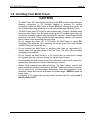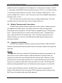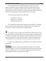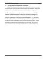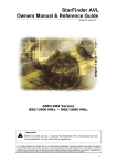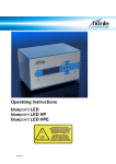
1
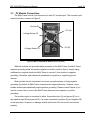
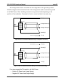
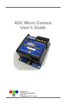
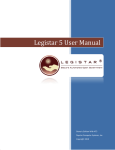
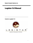
daystar, inc.
daystar, inc.
daystar, inc.
Energy Engineering
Photovoltaic
MULTI-TRACERS
RD-1600 —— RD-3200
Operations & Maintenance
Manual
Version 4.2
December 2007
RD-1600/3200 Operations Manual
Table of Contents
Table of Contents.......................................................................................................................i
Summary .....................................................................................................................................ii
WARNINGS .................................................................................................................................iii
NOMENCLATURE.......................................................................................................................iv
1.0
The Multi-Tracer ...............................................................................................................1
1.1
Electrical Loading..................................................................................2
1.2
Curve Tracing .......................................................................................3
1.3
PV Module Data Acquisition .................................................................3
1.4
Auxiliary Inputs......................................................................................4
2.0
Operating Software ..........................................................................................................5
2.1
Introduction ...........................................................................................5
2.2
Software Installation & Operation .........................................................5
2.3
The File Menu .......................................................................................7
2.4
The View Menu .....................................................................................7
2.5
The Execute Menu................................................................................7
2.6
The Configuration Menu .......................................................................7
2.7
The Windows Menu ..............................................................................10
2.8
File Types..............................................................................................11
3.0
Installing Your Multi-Tracer.............................................................................................16
CAUTIONS 16
3.1
Installation Procedure ...........................................................................17
3.2
Ground Connections .............................................................................18
3.3
PV Module Connections .......................................................................19
3.4
Voltage Drop & Isc ................................................................................21
3.5
Module Thermocouple Connections .....................................................22
3.6
Computer Connections .........................................................................22
3.7
Auxiliary Input & Temperature Connections .........................................24
4.0
Calibration, Maintenance, & Troubleshooting ..............................................................25
4.1
Calibration .............................................................................................25
4.2
Exterior Cleaning ..................................................................................25
4.3
Transportation.......................................................................................25
4.4
Troubleshooting ....................................................................................26
APPENDIX A—GENERAL SPECIFICATIONS ..........................................................................1
APPENDIX B—USB Drivers ......................................................................................................1
page i
RD-1600/3200 Operations Manual
page ii
Summary
The Multi-Tracer is an integrated measurement system for testing multiple
photovoltaic (PV) modules under natural or simulated sunlight. It is controlled with
MTRACE software operating on an IBM compatible computer (PC). This manual
contains instructions for setup, calibration, operation, and maintenance of either model
RD-1600 or RD-3200. A description of these units is given in Section 1 followed by
instructions for the operating software in the Section 2. The operating software will be
the information most often consulted after initial setup and calibration of the hardware.
Section 3 contains instructions for connecting the hardware and using the calibration
routines. Maintenance and Troubleshooting techniques are included in Section 4.
Performance specifications for the Multi-Tracers are provided in Appendix A.
To monitor PV module performance with a Multi-Tracer:
1) Become familiar with your unit and review all warning statements—Think Safety.
2) Start the PC, install, and setup the operating and calibration software.
3) Make connections from the modules to the Multi-Tracer. Connect pyranometers
and thermocouples (not provided) to the marked inputs.
4) Connect the PC to the Multi-Tracer using the Ethernet, USB, or serial port.
5) Run the MCAL calibration software.
6) Run the MTRACE configuration software.
7) Begin data collection.
Instructions for these steps are described in this manual.
Daystar Multi-Tracers are built to specification by Raydec, Inc.; 8210 La Mirada, NE, Suite
700; Albuquerque, NM 87109; 505-292-5002.
RD-1600/3200 Operations Manual
page iii
WARNINGS
IMPROPER USE OF THIS INSTRUMENT CAN PRESENT AN ELECTRICAL
SHOCK HAZARD THAT CAN CAUSE DEATH OR SERIOUS INJURY.
THIS INSTRUMENT SHOULD ONLY BE USED AS DESCRIBED IN THIS
OPERATIONS MANUAL.
***
THIS INSTRUMENT MAY PRESENT AN ELECTRICAL SHOCK HAZARD THAT
CAN RESULT IN DEATH OR SERIOUS INJURY IF THE FOLLOWING PRECAUTIONS
ARE NOT FOLLOWED:
•
THIS INSTRUMENT MUST ONLY BE USED FOR TAKING ELECTRICAL
CURRENT AND VOLTAGE (I-V) CURVES OF PHOTOVOLTAIC (PV)
MODULES.
•
THIS INSTRUMENT MUST NOT BE USED BEYOND ITS OPERATING RANGE
OF VOLTAGE, CURRENT, AND POWER AS DESCRIBED IN THIS MANUAL
AND SHOWN AT THE INPUT CONNECTIONS ON THE MULTI-TRACER’S
PANEL.
•
THIS INSTRUMENT MUST BE GROUNDED AS DESCRIBED IN THIS
MANUAL.
•
THIS INSTRUMENT MUST ONLY BE USED BY PERSONNEL WHO HAVE
EXPERIENCE HANDLING HIGH VOLTAGE DC PHOTOVOLTAIC SOLAR
MODULES.
•
THIS INSTRUMENT IS INTENDED FOR USE IN AN AIR CONDITIONED
ENVIRONMENT.
•
THIS INSTRUMENT MUST NOT BE USED IF IT IS NOT FUNCTIONING AS
EXPECTED (REFER TO USER MANUAL FOR PROPER OPERATION).
•
MULTI-TRACERS ARE HEAVY—USE TWO (2) PEOPLE WHEN LIFTING OR
MOVING THE UNIT TO AVOID BACK OR MUSCLE INJURIES.
RD-1600/3200 Operations Manual
page iv
NOMENCLATURE
I-V
Current-Voltage
PV
Photovoltaic
V Voltage
I
Current
A Amperes or Amps
Hz
Hertz
Voc
Open-Circuit Voltage: The maximum voltage a photovoltaic cell can
generate with the output terminals open circuited.
Isc
Short-Circuit Current: The maximum current photovoltaic cell can
generate with the output terminals shorted
RD-1600/3200 Operations Manual
page 1
1.0 The Multi-Tracer
This manual provides instructions for the proper set-up and use of the RD-1600 or the
RD-3200 Multi-Tracer photovoltaic I-V curve tracer. These units provide an integrated
measurement system for testing multiple photovoltaic (PV) modules under natural or
simulated sunlight. The Multi-Tracer is designed to interface with an IBM compatible
computer (PC). Some of the features offered are:
•
•
•
•
•
Peak-power, fixed voltage, or user-set voltage profile electrical loading of PV
modules.
Periodic I-V curve measurement of attached modules.
PV module voltage, current, and temperature data acquisition.
Pyranometer and ambient temperature data acquisition.
Rugged MOSFET loads with individual over voltage and thermal cut-off
protection on each load transistor. The RD-1600 can dissipate 1200 W steadystate. The RD-3200 can dissipate 2400 Watts.
Figures 1 and 2 show the front and back panels of an RD-1600. The RD-3200 is similar in
appearance but housed in two rack-mountable cases.
Figure 1. Face plate of the Multi-Tracer.
RD-1600/3200 Operations Manual
page 2
Figure 2. Back plate of the Multi-Tracer .
1.1
Electrical Loading
Each Multi-Tracer has separate and isolated inputs for a number of PV modules.
Because each unit is built to custom specifications, please consult the specification sheet
your specific unit. Under software control, the Multi-Tracer independently loads each
module and operates each at its peak-power point, at a set voltage value, or at a userdefined voltage profile. For example, modules 1, 3, 4, 5, and 13 could be operated at their
respective peak-power points while modules 2, 6, 7, 8, and 9 operate at a fixed voltage of
12 V and modules 10, 11, 14 and 16 operate at voltages that change with time as defined
by the voltage profile. The actual functions available to the user are defined by the
operating and control software. See Section 2.0 for the details on the MTRACE operating
software.
The Multi-Tracers can operate PV modules at voltages from slightly greater than 0 V
to their Voc value. The Multi-Tracer controls the module voltage to a resolution of
approximately 1/30,000 of the maximum voltage for that input channel. For example, if the
Multi-Tracer input channel is rated for 100 V DC, the control resolution is 3 mV—100
V/30,000. The MTRACE operating and control software must periodically update the
settings of the loads. The rate depends on the software and the speed of the control
computer, but is typically once every second.
While peak-power tracking, the Multi-Tracer sweeps the module voltage up and down
as it searches for maximum power from the module. Although the search ranges over a
RD-1600/3200 Operations Manual
page 3
significant voltage range, perhaps as much as ±0.5 V, the power from the module will be
within 0.2% of the maximum power after the Multi-Tracer has achieved peak-power
tracking.
Because the Multi-Tracer does not “know” the module characteristics when a new
module is connected, the user should follow the recommended procedure for connecting
modules. Otherwise it may take many minutes for the Multi-Tracer to locate the peakpower point and begin tracking.
The Multi-Tracer should be turned OFF when connecting modules
to the unit.
The AC power switch is on the back panel. Leave the power off for a minimum of 5
seconds after connecting a module to ensure the RD-1600 will sense the module Voc. The
peak-power tracking algorithm uses the module Voc to estimate and quickly reach the
peak-power point.
1.2
Curve Tracing
In addition to electrically loading the PV modules, the Multi-Tracers can generate a
current-voltage (I-V) curve that characterizes the photovoltaic modules under test. At userdefined intervals, the Multi-Tracer sweeps an I-V curve from Isc to Voc for each module
connected. Because of wiring and other load resistance, the Multi-Tracer cannot operate
the modules at true Isc (zero voltage). The RD-1600 does make voltage-current
measurements for voltages near zero—typically less than 0.5 V at full-scale current. Wiring
resistance from the PV module to the Multi-Tracer is the major factor in preventing
operation at zero volts. Refer to Section 3 for details on module connections and
resistance calculations.
1.3
PV Module Data Acquisition
The Multi-Tracer has several connection options to the control computer. Ethernte,
USB, or serial RS-232. The connection allows the Multi-Tracers to be located near the
module while the host PC may be located hundreds of feet away if necessary if using
RD-1600/3200 Operations Manual
page 4
ethernet. (Caution: Do not exceed temperature limits of the Multi-Tracer.)
Some of the basic analog measurement features are:
•
•
•
Module voltage using a 4-wire connection and resistive voltage dividers.
Module current using 50 mV current shunts (at full scale).
Module temperature using type T thermocouples.
A 16 bit A/D with a nominal ±5 V input range is used for data acquisition in the MultiTracer. Voltage measurements are made using resistive voltage dividers and are wired
differentially. These signals are multiplexed and sent to the A/D board. The current shunt
signals are amplified before being applied to the A/D. The thermocouple inputs are also
amplified before applying A/D conversion. The data sampling rate is determined by the
operating software.
1.4
Auxiliary Inputs
Each Multi-Tracer has additional inputs for pyranometers and thermocouples. Refer
to Appendix A for details. In general, these inputs are suitable for pyranometers and
reference cells—reference cells require external shunt resistors.
RD-1600/3200 Operations Manual
2.0 Operating Software
2.1
Introduction
MTRACE is a Windows-based program designed to control and operate the Multi-
Tracers. It implements all data collection features as well as timing, averaging, and
storing data on disk. As a Windows program, MTRACE incorporates most of the
features of that operating environment—common Windows techniques using the mouse
or keyboard commands will allow the user to quickly become comfortable with
MTRACE.
For testing PV modules under simulated sun conditions, MTRACE allows the user
to set the number of microseconds (uS) that will be averaged to obtain values for a
module I-V curve. This option permits modules to be operated under a variable light
source. In this mode, the load provided to the module by the Multi-Tracer is fixed until
the data are obtained and averaged to determine the value of voltage and current.
Then the load is stepped to the next value and the process is repeated. The MultiTracers will operate with a mixture of modules, some in artificial light and others in
natural conditions.
2.2
Software Installation & Operation
A number of files and a specific directory structure are required for MTRACE
operation. These files are included on the installation CD-ROM. MTRACE is a
Windows® application and must be installed on Windows 2000®, or Windows XP®.
Operation on other Windows® versions may be possible, but has not been tested.
Insert the CD-ROM and the setup program will prompt you for information on
where you want to install MTRACE. If you are unsure, use the defaults which create
appropriate sub-directories in the programs folder.
MTRACE Setup automatically installs the necessary files in the designated
directory and makes additions to your Windows system directory. Setup also creates a
new program group icon in the program manager window.
page 5
RD-1600/3200 Operations Manual
page 6
Double click on the MTRACE icon to start MTRACE. A setup screen similar to that
shown in figure 1 will be displayed. Menu actions may be executed with the mouse or
keyboard. Pertinent event time status is displayed across the bottom of the screen. These
fields are updated to show the ongoing activity of the Multi-Tracer. On successive startups
of MTRACE, the configuration parameters that were last used will be loaded. If other
parameters are desired, use the Load Configuration command under the File menu to
load previously saved MTRACE configurations (“.MTC” files).
Figure 1. MTRACE Screen
Note: The hardware must be calibrated before you setup MTRACE for the first
time. Your Multi-Tracer has been factory calibrated, but you may prefer to perform
an onsite calibration using the MCAL software. See the instructions for running
MCAL in Section 4
RD-1600/3200 Operations Manual
2.3
page 7
The File Menu
Four active sub-menus may be accessed from the File menu.
About—shows information about the MTRACE software program
Load Configuration—user may search for and load a previously saved file
Save Configuration—user may designate a location and save a configuration file
Exit—user may exit MTRACE
2.4
The View Menu
Four active sub-menus may be accessed from the View menu.
Active Channels—displays status data for active channels.
Temp & Aux—displays data from connected temperature/irradiance sensors.
Error Log—displays all Mtrace errors to date. Can be cleared.
Last Curve—displays last I-V curve taken of the specified channel.
These windows may be selected, moved, or re-sized using the mouse and normal
Windows techniques.
2.5
The Execute Menu
Three active sub-menus may be accessed from the Execute menu.
Calibrate—offers the user the opportunity to Quit MTRACE and run the calibration
program MCAL. Note: MCAL and MTRACE cannot run at the same time.
Reset Hardware—will re-establish communications between the PC and the MultiTracer and re-initialize the Multi-Tracer. Note: This is done automatically each
time MTRACE is started.
Take Curve—allows the user to manually take an I-V curve on one or more modules.
2.6
The Configuration Menu
Eight active sub-menus may be accessed from the Configuration menu.
Channels—displays status data for selected channel in an editable window. User
may enter/change information using the keyboard, moving from field to field
using the "Tab" key. Data in the "aperture" and "system areas" are used to
calculate the efficiencies displayed for the I-V curve display and the active
channel window. "Irradiance Channel" is used to select the pyranometer input
channel for this module. Channels 1 through 8 are external voltage inputs;
channel 9 is a manual input. "Aux. Temp(erature). Channel" is used to select the
RD-1600/3200 Operations Manual
page 8
auxiliary temperature channel associated with this module. I.E., secondary
temperature.
The Aux String control defines if auxiliary string data is collect for a given channel
when and I-V curve is taken. Also the starting character position and number of
string characters can be specified. Refer to the configuration menu for auxiliary
string data for more details.
Note: Average __1__ uSeconds should be set to “100” unless testing under
simulated light is in progress. To take accurate sample data or I-V Curves under
varying light sources the Average should be increased because the output of
many artificial light sources pulsate due to their power sources. To obtain valid
data under such light sources, the RD-1600 Multi-Tracer averages a number of
data points at each load setting to obtain data points. The higher the number,
the longer it takes to sample data or take an I-V curve, and, theoretically, the
better the data. Experience shows that after a certain point, any improvement
becomes exceedingly small.
Because the averaging period can be set in uS, it is possible to define the
average period equal to the pulse period (or multiple of pulse periods) of the
artificial light source. This makes it possible to dramatically reduces the variations
caused by an artificial light.
The amount of averaging, number of data points, and speed of IV curves and
sampling depends not only on the light source but the type of module tested and
the quality of the data desired. This operator decision will be based on
experience with the RD-1600.
IV Curves—offers user control for taking I-V curve; how often, when, under what
irradiance conditions are data to be collected, and where curves are to be saved.
Standard Windows folder (directory) selection boxes are available to select which
folder is used to store I-V curve data. The “New Folder” button allows a new
folder to be created.
Global—allows the user to set commands for all attached modules. The Global
command displays two selection boxes with radio control buttons, one for Load
RD-1600/3200 Operations Manual
page 9
Control and one for Setting I-V Curve data acquisition. "Load Control" options
include All Loads Off, Peak Power Tracking for all modules, Fixed Voltage
Operation for all modules, Voltage Profile for all modules, and Channel Defined.
For channel defined operation, the settings from the Channels configuration (see
above) are used.
Selections in the "I-V Curves" area include None, All Channels, and Channel
Defined. The I-V curve parameters of when and under what conditions I-V curve
are taken still apply. This setting overrides the “Enable I-V Curve” selection from
the channels configuration.
Global control does not edit channel configurations, but rather overrides the
current channel settings. Global control provides as convenient short term
testing, but can be used for all testing if, for example, all modules are to be peakpower tracked.
Data Logging—allows user control of the sample interval, number of samples to
average, and where to save the data. The "Average Interval", entered in
minutes, is the time over which data are averaged and written to disk. Note: a
small average interval will result in relatively large amounts of data written to
disk. Also, this average is not to be confused with the averaging when taking
data under simulated light sources.
As with I-V curves, the folder used for storing sampled data may be selected.
Sampled data files are designated by the “.MTD” file type.
Voltage Profile—opens a spreadsheet that allows an entry for every 15 minutes for
up to 16 modules. This spreadsheet format simplifies data entry through use of
copy, cut, paste, and fill commands. This mode of operation is very similar to
fixed voltage operation except the fixed voltage values are updated every 15
minutes. Note: Due to load control regulation, voltage changes do not occur
instantly, but may take several update cycles to change to the updated value.
Auxiliary Scales—allows user input of conversion factors (units/volt). Channel 9 is
not a true data channel, i.e.., a pyranometer is not used, but accepts a manual
RD-1600/3200 Operations Manual
page 10
input in Watts/m2. The value entered here will be used for any channels which
specifies channel 9 as its irradiance channel.
Although these channels are typically used for irradiance measurements, they
may be used for any signal meeting the input specifications. Note: Standard
voltage inputs have a maximum range of ± 5 V. In all cases inputs are auto
scaling in decades providing accurate measurement of even mV signals.
Port—allows the selection of which port to use and values appropriate to that port.
Aux String—allows the user to set the parameters and port for adding auxiliary string
data to I-V curve files. Auxiliary string data can be recorded and saved with any IV curve. This string data can come from any serial COM port. No limitation is
placed on the source of this data other than a string is defined as data terminated
by a carriage return. Baud rate and other serial port parameters are set in this
menu. Note: The time-out parameter sets how long the I-V curve routine should
wait for string data. Furthermore, auxiliary string data is completely
asynchronous. MTRACE does not perform any handshaking with the string data
source.
2.7
The Windows Menu
This sub-menu shows open and active windows and serves as an alternate method
for selecting windows.
RD-1600/3200 Operations Manual
2.8
page 11
File Types
2.8.1 Data Files:
Mtrace works with the following file types:
“MTRACE.CFG”—this is the calibration and hardware configuration file created by
MCAL. This file is unique for every unit and stores the calibration constants.
“.MTC”—These are the MTRACE configuration files used by MTRACE to store the
various channel, I-V curve, data logging and other parameters. The default file is
“MTRACE.MTC”, but any configuration file may be used. Use the Load and Save
commands under the file menu. The last used MTC file is automatically used when
MTRACE is restarted. The file name is displayed as part of the title in the MTRACE
window.
“.MTD”—These are the sample data files. There is a separate file for each day’s
data. All channel and auxiliary input data are stored in this file.
The naming convention for data files is 'MTyymmdd.MTD' where:
•
•
•
yy is the year,
mm is the month, and
dd is the day of the month.
The files are created daily and contain data for that day. The data are comma
delineated ASCII and can be viewed with a text editor or imported into a spreadsheet.
RD-1600/3200 Operations Manual
page 12
Each line of data in the data file contains all data channels for that particular time or
average interval along with a time stamp. An example data file created on March 16, 2007
is shown below. It contains the first 15 averaged data values after which the voltage,
current, power, and temperature of each connected module would be written. A description
of each field in a data line is given below the example file.
MT070316.MTD
(file name, not included in file)
07,03,16,6,00,0,0,0,0,0,0,0,0,0,0,0,0,0,0,0,0,0...
07,03,16,6,15,0,0,0,0,0,0,0,0,0,0,0,0,0,0,0,0,0...
07,03,16,6,30,0,0,0,0,0,0,0,0,0,0,0,0,0,0,0,0,0...
07,03,16,6,45,0,0,0,0,0,0,0,0,0,0,0,0,0,0,0,0,0...
07,03,16,7,00,0,0,0,0,0,0,0,0,0,0,0,0,0,0,0,0,0...
07,03,16,7,15,0,0,0,0,0,0,0,0,0,0,0,0,0,0,0,0,0...
07,03,16,7,30,0,0,0,0,0,0,0,0,0,0,0,0,0,0,0,0,0...
07,03,16,7,45,0,0,0,0,0,0,0,0,0,0,0,0,0,0,0,0,0...
07,03,16,8,00,0,0,0,0,0,0,0,0,0,0,0,0,0,0,0,0,0...
07,03,16,8,15,0,0,0,0,0,0,0,0,0,0,0,0,0,0,0,0,0...
RD-1600/3200 Operations Manual
Field
1
2
3
4
5
6
7
8
9
10
11
12
13
14
15
16
17
18
19
20
21
22
23
24
25
26
27
28
29
.
.
.
Description
year
month
day of month
hour
minute
AUX Input 1
AUX Input 2
AUX Input 3
AUX Input 4
AUX Input 5
AUX Input 6
AUX Input 7
AUX Input 8
AUX TEMP 1
AUX TEMP 2
AUX TEMP 3
AUX TEMP 4
AUX TEMP 5
AUX TEMP 6
AUX TEMP 7
AUX TEMP 8
V1 (Voltage for channel 1)
I1 (Current for channel 1)
T1 (Temperature for channel 1)
P1 (Power for channel 1)
V2
I2
T2
P2
.
.
.
page 13
RD-1600/3200 Operations Manual
page 14
2.6.2 I-V Curve Files & Formats
The MTRACE I-V curve files use the DS-Tracer “IVA” file format. File names are
created with a time and channel stamp — mmddhhmm.nnc— where:
•
•
•
•
•
•
mm is the month,
dd is the day of the month,
hh is the hour,
mm is the minute, and
nn is the channel number of the I-V curve.
c is a single character file designator defined by the user (a, b, c
etc.).
Each line of the file starts with a unique ID followed by a space. The ID and space are
used to decode the file. Note: Line starting with the letter ‘A’ are considered auxiliary data
lines and are not recognized as part of a standard DS- Tracer file. Therefore, other
programs such as IVPC for the DS-Tracer can read these files, but will ignore the auxiliary
data. The format is:
F
D
T
S
B
M
P
Q
R
X
H
O
C
K
W
L
A1
A2
A3
A4
A5
A6
A7
A8
A9
A10
A11
“MTrace”
Date
Time
Site
Sub-system
Module ID
Module Temperature Before I-V Curve
Ambient Temperature Before I-V Curve
Irradiance Before I-V Curve
Channel Number
Short circuit current
Open circuit voltage
Current at peak power
Voltage at peak power
Peak power
Fill factor
AUX 1
AUX 2
AUX 3
AUX 4
AUX 5
AUX 6
AUX 7
AUX 7
AUX TEMP 1
AUX TEMP 2
AUX TEMP 3
RD-1600/3200 Operations Manual
A12
A13
A14
A15
A16
A17
A18
A19
A20
A21
A22
A23
AUX TEMP 4
AUX TEMP 5
AUX TEMP 6
AUX TEMP 7
AUX TEMP 8
System Area
Aperture Area
System Efficiency
Aperture Efficiency
Module Temperature After I-V Curve
Ambient Temperature After I-V Curve
Irradiance After I-V Curve
I
I
..
current value voltage value
current value voltage value
(There may be up to 257 IV data pairs)
page 15
RD-1600/3200 Operations Manual
page 16
3.0 Installing Your Multi-Tracer
CAUTIONS
•
•
•
•
•
•
•
•
The Multi-Tracer AC Power switch should be in the OFF position when making or
breaking connections to PV modules. Making or breaking PV module
connections while the Multi-Tracer is turned ON (fans blowing) may cause an
arc. Electrical arcs may cause burns to the user and damage the Multi-Tracer.
The Multi-Tracer uses DC fuses for each module input. However, because these
fuses are rated higher than the rated current of the PV module inputs, they will
not provide protection against short-circuiting PV modules. These fuses provide
protection to the Multi-Tracer should the user inadvertently connect a PV module
with a current output exceeding the input rating.
Do not change any fuses (AC or DC) when the Multi-Tracer is turned ON.
Changing a fuse while the unit is operating can cause an arc that could damage
the Multi-Tracer and injure the user.
Do not connect the Multi-Tracer to anything other than an ungrounded PV
module within the operating range of the unit. Note: The Multi-Tracer provides
grounding to the modules.
Do not connect the Multi-Tracer to a PV module with an open-circuit voltage
(Voc) greater than the maximum voltage for the that input channel.
Do not connect the Multi-Tracer to any PV module with a short-circuit current (Isc)
greater than the maximum current for the that input channel.
Module input channels have different ratings. The input voltage, current, and
power ranges are printed on the back of the Multi-Tracer next to each connector.
Do not exceed any of these ranges. Specifically, note that the product of the
maximum voltage and current far exceeds the power range. NEVER exceed the
power range.
Connecting a PV module with reverse polarity will short the PV module even if
the AC power is OFF.
RD-1600/3200 Operations Manual
3.1
page 17
Installation Procedure
CAUTION
The Multi-Tracer is intended for installation indoors. In general, the unit should be
operated at room temperature (25°C). The full operating range is listed in Appendix A.
More accurate measurements are made if the Multi-Tracer is operated at the temperature
used during calibration. The Multi-Tracer is packaged for desk-top mounting although
optional rack-mount ears are provided. Note: When rack mounting, use equipment slides to
support the weight of the unit. In all installations, leave a minimum of one foot clearance
both front and back for airflow. Special care should be taken to ensure proper grounding
as described in the following section. Proper grounding helps prevent fire and shock
hazards. It will also aid in minimizing noise in measurements.
The basic connections of the Multi-Tracer are shown in Figure 3. Note that the MultiTracer and PC are grounded at the same location and that the PV modules are grounded
inside the Multi-Tracer. Referencing the PV modules to ground at any other point will
cause measurement errors and could possible present a safety hazard. If the PV modules
are disconnected from the Multi-Tracer they will lose ground reference and possibly create
a shock hazard. The connectors supplied, for mounting to the PV module cables, are
recessed and are difficult to come in contact with. However, treat all disconnected cables
carefully.
PV
Mod ule
Multi-Tracer
Ethernet, USB, or RS-232
AUX. GN D
Desk-Top
PC
AC
GN D
AC
GN D
EARTH
GN D
Figure 3. MULTI-TRACER Basic Connections.
RD-1600/3200 Operations Manual
3.2
page 18
Ground Connections
As shown in Figure 3, there are three ground connections—two to the Multi-Tracer
and one to the PC. The PC ground connection is provided by the 3-prong plug of your
computer’s AC power cord. The Multi-Tracer has a similar 3-prong power cord with a
ground. The third connection to ground is a case ground for the Multi-Tracer. This ground is
necessary to ensure the Multi-Tracer case remains grounded for the worst case condition
of having all PV module currents flowing to ground. The Multi-Tracer AC power cord is not
capable of handling this much current. Therefore this separate ground point is provided as
shown in Figure 4.
Figure 4. MULTI-TRACER Ground Connector.
Connect a #2 AWG wire with lug to the Multi-Tracer ground connector. Be sure to
securely attach the lug to the mounting post shown in Figure 4. Keep this ground lead as
short as possible and firmly attach it to the ground system. All ground connections should
be made to the same point. Note: Significant voltage potentials can exist between grounds.
Therefore, the AC power grounds used for the 3-prong plugs must be connected to the
same ground as the #2 wire from the Multi-Tracer. Be sure that the ground connection is
capable of handling the total current from all of the PV modules connected to the system.
Note: For model RD-3200 the slave load must be connected to the master load to
properly ground all module. Do not run the RD-3200 without having both loads connected
and grounded.
RD-1600/3200 Operations Manual
3.3
page 19
PV Module Connections
The Multi-Tracer uses a 5-pin connector for each PV module input. The connector and
each pin function is shown in Figure 5.
Ground (E)
+ PV (A)
- Voltage Sense (D)
+Voltage Sense (C)
- PV (B)
Figure 5. MULTI-TRACER PV Module Input Connector.
While all modules are grounded when connected to the Multi-Tracer, the Multi-Tracer
supports grounding either the module negative or module positive. Note: A simple wiring
modification is required inside the Multi-Tracer to convert it from positive to negative
grounding. Therefore, each channel is predefined as a positive or negatively ground
channel.
Most modules can be connected in the more conventional way of using negative
grounding. By default all Multi-Tracer channels are configured this way. However, some
module technologies specifically require positive grounding. Please consult Daystar if you
need to convert one or more of the Multi-Tracer channels from negative to positive
grounding.
The module output is connected to either the positive input (A) and ground (E) or to
the negative input (B) and ground (E). It is never connected to positive (A) and negative (B)
at the same time. However, no damage should result result. But the unit will not function
properly.
RD-1600/3200 Operations Manual
page 20
The voltage sense lead is connected the same regardless of the grounding scheme.
While the diagrams below show the shield of the voltage sense cable connected to ground
at the Multi-Tracer. Other shielding connections may perform better depending on the
specifics of the installation. Generally it is best to connect a shield at one end only.
+ PV (A)
+
+ Voltage Sense (C)
PV
Module
- Voltage Sense (D)
Ground (E)
No Connection
- PV (B)
Figure 6. MULTI-TRACER PV Module Wiring. For Negative Grounding
No Connection
+ PV (A)
Ground (E)
+
+ Voltage Sense (C)
PV
Module
- Voltage Sense (D)
- PV (B)
Figure 7. MULTI-TRACER PV Module Wiring. For Positive Grounding
Four wires connect the PV module to the Multi-Tracer:
•
•
Positive PV Power Lead (Large Gauge).
Negative PV Power Lead (Large Gauge).
RD-1600/3200 Operations Manual
•
•
page 21
Positive Voltage Sense Lead
Negative Voltage Sense Lead
Use a shielded, twisted-pair wire with a voltage rating greater than Voc of the PV
module for the voltage sense lead. Connect the shield of this cable to pin E of the MultiTracer or other suitable ground point. Only connect the shield at one end. Keep the power
leads as short as possible and use #12 AWG wire. This is the largest wire that can be
used with the Multi-Tracer connectors. After crimping the pins to the lead, solder may be
used to minimize the voltage drop across the connection.
3.4
Voltage Drop & Isc
It is important to minimize the resistance in all circuits. The lower the short-circuit
resistance, the closer to true Isc the Multi-Tracer will operate. If the voltage drop is too
large, it becomes unacceptable to use the current measurement at this minimum voltage as
an approximation of Isc. The following example illustrates the effect of lead resistance on Isc
measurement.
If a PV module with an Isc of 10 Amperes is connected using 20 foot leads of #12 wire
the voltage drop near Isc may be estimated as:
•
Isc = 10 A
•
Rwire = 1.6 mΩ/ft (specification for #12 stranded copper wire)
Rtotal = 1.6 mΩ /ft x 40 ft = 64 mΩ (20 ft Module to Multi-Tracer and 20 ft back)
•
• Vdrop = Isc x Rtotal = 10 A x 64 mΩ = 640 mV = 0.64 V
Add to this the internal resistance of the Multi-Tracer and it may be impossible to get
closer than 1 V to true Isc. For this reason, the lead length must be minimized. If longer
leads are necessary use larger wire for most of the distance and attached #12 tails to this
wire to fit in the mating connector of the Multi-Tracer.
Use calculations similar to the above example to determine wiring loses. As module
voltage increases, voltage drops become a smaller percentage of Voc. Therefore the values
are closer to Isc relative to the I-V curve Voc. Additionally, higher Voc will result in lower Isc
for the same power. Lower currents create lower voltage drops. Inversely, lower voltage
RD-1600/3200 Operations Manual
page 22
modules increase the significance of the voltage drop. In the previous example, Isc was 10
A. Assuming a standard Multi-Tracer module input power of 100 W, Voc would be less than
13 V assuming an 80% fill-factor PV module. Given a combined voltage drop of 1 V, the
minimum voltage is 8% of this Voc value. This may or may not be acceptable depending on
the shape of the I-V curve.
Note: This issue does not affect the accuracy of voltage measurements. The 4-wire
connection removes wire losses as a source of measurement error.
3.5
Module Thermocouple Connections
The Multi-Tracer includes a thermocouple input for each module. Mating connectors
are supplied with the Multi-Tracer. Use these connectors as well as the appropriate
thermocouple wire (not supplied). The Multi-Tracer is equipped with type T thermocouple
inputs. Thermocouple inputs do not have a shield connection point. If shielded wire is
used, connect the shield to the thermocouple. Note: The thermocouple inputs are not
isolated. Therefore you must use un-bonded thermocouples (thermocouples must be
electrically insulated).
3.6
Computer Connections
The Multi-Tracer supports 3 different connections types; Ethernet, USB, and RS-232.
Ethernet is recommended unless the Multi-Tracer and controller computer are located near
each other.
Ethernet
The Multi-Tracer has a standard 10/100 Ethernet port and can be connected to the
LAN common to the controller computer. While the data rates of the Multi-Tracer are
relatively low, performance may be affected by other network traffic. Therefore, for best
performance, the recommended connection is to connect the Multi-Tracer and controller
computer into a networks switch and connect this switch to the LAN. This will keep LAN
traffic from affecting the Multi-Tracer, but still allow the control computer to use the LAN.
In order to use the Ethernet connection, the Multi-Tracer needs a unique network IP
address. While the Multi-Tracer does support DHCP, assigning a static IP address to the
Multi-Tracer is the simplest and most reliable approach.
RD-1600/3200 Operations Manual
page 23
Note: Both the Multi-Tracer and MTrace software must be set to the same IP
address. Use the MCAL software to change the Multi-Tracer network settings. Keep in
mind that typically it is impossible to properly change the Multi-Tracer network settings
using the network connection. Therefore, it is recommended that the USB or serial RS-232
connection be used temporarily to change the Multi-Tracer network settings.
The following values may be set for the Multi-tracer:
IP Address (I.E., 10.0.0.10)
Netmask (I.E. 255.255.255.0)
Gateway Address (optional)
The IP address and net mask must be assigned (unless using DHCP). The gateway
address is only used if the controller computer and Multi-Tracer do don’t operate on the
same network. Therefore, the gateway value is typically left blank.
USB
If the controller computer is located near the Multi-Tracer a USB connection may be
used. Even if Ethernet is used, the USB connection may be needed to setup the network or
for calibration. For example, when calibrating it is essentially a requirement that the control
computer and Multi-Tracer be near each other. However, a notebook computer could be
used temporarily if the control computer is located some distance from the Multi-Tracer.
In order to use the USB connection, the USB drivers must be installed as described
in Appendix B.
RS-232 Serial
Serial RS-232 ports, commonly called COM ports), may also be used. The MultiTracer uses COM port 1 for control (see back panel) while the MTrace and MCAL software
may use any COM port from 1 to 16. Use the port settings dialog in MTrace and MCAL to
set the appropriate COM port used by the control computer.
RD-1600/3200 Operations Manual
3.7
page 24
Auxiliary Input & Temperature Connections
Auxiliary thermocouple input connections are the same as the module thermocouples.
They use the same circuitry and have the same limitations and specifications. These inputs
may be used for any temperature measurements such as ambient air temperature.
The auxiliary inputs are commonly used for pyranometer measurements. Refer to
Appendix A for detailed specifications. In either case, these inputs use standard BNC
connectors. It is recommended that coax or shielded cable be used. This will minimize
noise in the measurements. These inputs are quasi-differential with a 10 K ohm resistor
from the negative (shield) input to the Multi-Tracer ground. Therefore signal sources such
as reference cells and pyranometers may be connected if grounded or floating. However,
grounded signals typically have less measurement error due to noise. All inputs must
remain within the common mode range of the Multi-Tracer as specified in Appendix A.
RD-1600/3200 Operations Manual
page 25
4.0 Calibration, Maintenance, & Troubleshooting
4.1
Calibration
Calibrate the Multi-Tracer using the MCAL.EXE software supplied with the Multi-
Tracer. This software provides a step-by-step guide to the calibration. Complete calibration
details are supplied in the help screens of the MCAL program. In general, a full calibration
is recommend every 6 months; more often if the Multi-Tracer is operated over varying
temperatures or if it is moved or shipped. MCAL is also a Windows based application and is
installed by running the “Setup” file on the MCAL installation disks.
The basic steps of calibration are:
• Software calibrate each module voltage.
• Software calibrate each module current.
• Software calibrate each auxiliary input.
Equipment needed for calibration includes:
• Voltage source with output near the full-scale voltage of each module.
• Current source with output near the full-scale current of each module.
• Low voltage (mV) source for calibrating auxiliary inputs.
By following the step-by-step procedure outlined in the MCAL program, a complete
unit calibration can be done in less than 2 hours. Since each module input must be
calibrated independently, the calibration goes much more quickly if precision voltage and
current sources are used. This allows constant inputs and avoids having to re-type a new
value into the program for every module.
4.2
Exterior Cleaning
The exterior surface of the Multi-Tracer should be cleaned with a soft damp cloth only.
Do not use detergents, abrasive cleansers, or other solvents. Turn the Multi-Tracer OFF
and disconnect AC power and all module and signal inputs before cleaning.
4.3
Transportation
The Multi-Tracer should be treated with the same care used for a desk-top computer.
Specifically:
•
Do not bump, drop, or otherwise jar the unit, particularly during operation.
RD-1600/3200 Operations Manual
•
•
4.4
page 26
Double box and pack with at least 3 inches of packing foam between the inside
and outside boxes for shipping.
Use two people when lifting or moving the unit.
Troubleshooting
All modules are always at Voc.
• The Multi-Tracer has no AC power (fans not blowing).
—Turn AC power ON using the switch on the back panel.
Multi-Tracer is turned ON and fans are not blowing.
• AC power fuse has blown.
—Turn AC power OFF, unplug AC power cord, replace fuse, reconnect AC
power cord, and turn AC power ON.
A single module is always at Voc.
• Input fuse for module has blown.
—Turn Multi-Tracer OFF, replace fuse, and turn unit ON.
• Fixed voltage or load profile voltage is set above module Voc.
—Correct channel fixed voltage setting and load profile.
• Load has overheated and thermal protection circuit has activated.
—Check that module power is less than maximum for that channel and that
Multi-Tracer is operating within its operating range.
Single module is always near 0 V or negative.
• Module is not connected.
—Turn Multi-Tracer OFF, connect module, and turn Multi-Tracer ON.
• Module polarity is reversed.
—Turn Multi-Tracer OFF and carefully disconnect module. CAUTION:
Shade PV module before disconnecting to prevent arcing. Be sure to
wear proper eye protection and gloves to provide protection from
electrical arcs.
Measurements are incorrect
• The Multi-Tracer needs calibration
—Calibrate using MCAL software.
• Using out-of-date “.CFG” file.
—Use most recent calibration data (configuration file).
RD-1600/3200 Operations Manual
page A1
APPENDIX A—GENERAL SPECIFICATIONS
General Specifications
Number of Module Inputs
16
Number of Aux. Inputs
8
Number of Aux. Temp.
8
Approximate Size of Each Load Unit
14”H x 18”W x 35”D
Power
120 VAC, 70W RD-1600, 140W RD-3200
AC Fuse
3A, 250 V Slow Blow 3AG
Module Fuse
250 V Fast Blow 3AG. Amperage varies, refer to back panel.
Connectors
Module Connectors
97-4102A-18-11P
by Amphenol
Module Cable Connectors
97-4106A-18-11s
by Amphenol
Crimp Connector Pins
97-38-1216P(920)
by Amphenol
Crimp Connector Sockets
97-38-1216S(920)
by Amphenol
Thermocouple Sockets
MPJ-T-F
by Omega Engineering
Thermocouple Plugs
SMP-T-M
by Omega Engineering
Aux. Inputs
BNC
1
RD-1600/3200 Operations Manual
page B1
APPENDIX B—USB Drivers
In order to use the Multi-Tracer USB port for control, the Multi-Tracer USB drivers
must be installed on the control computer running MTrace and MCAL. The driver will be
a USB device driver labeled “Multi-Tracer”.
The Multi-Tracer USB drivers are located on the installation CD-ROM supplied
with the unit in the USB Drivers folder. This folder contains detailed instructions on how
to install the drivers for your version of the operating system.
Note: These instructions are not specific to the Multi-Tracer and where provided
by the USB hardware manufacturer. Therefore these instructions will not refer to the
Multi- Tracer driver by name.
When you first connect the Multi-Tracer to your computer using the USB
connection, Windows will recognize that new hardware has been connected and begin
the process of installing the driver. The instructions on the CD-ROM provide much more
detail, but in general, you will want to have Windows use the drivers in the driver folder
on the CD-ROM using the “Have Disk” option.
1