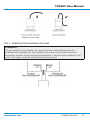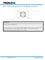
1
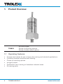
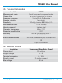
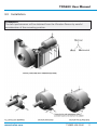
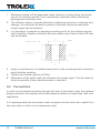
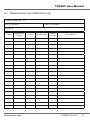
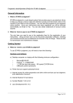
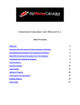
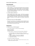
TX5633 User Manual
TX5633 Vibration Sensor
Contents
1.
Product Overview
4
3.4Connections
1.1
Operating Features
12
4
3.4.1 Electrical Connections
1.2Application
5
1.3
5
3.4.2 Electrical Connections to 4 Pin
1.4Dimensions
6
1.5
Technical Information
7
4.Maintenance
15
1.6
Electrical Details
7
4.1Introduction
15
2.Certification
8
4.1.1 Vibration Sensor - Check
15
2.1
Europe (ATEX)
8
4.1.2 Vibration Sensor - Calibrate 15
2.2
International (IECEx)
8
5Disposal
16
2.3Australia
9
6
Maintenance Records
16
2.4
Russia (GOST-R)
9
6.1
Maintenance and
3.Installation
10
Calibration Log
3.1
Safety Precautions
10
Disclaimers18
3.2
Tools and Test
Equipment Required
Product Options
3.3Installation
www.trolex.com
to Lead
13
MS Type Connector
14
17
Trademarks18
10
Contact Details
18
11
Document History
18
TX5633-UM-EN-01
3
1. Product Overview
TX5633
ac output signal
Choice of mounting options
Choice of cable output options
1.1 Operating Features
•
•
•
•
•
•
4
Compact and robust for use in heavy duty mining and industrial applications
Corrosion resistant stainless steel housing
Choice of mounting options
ac signal output
Certified for use in mining or hazardous industrial areas
No moving parts
TX5633-UM-EN-01
www.trolex.com
TX5633 User Manual
1.2Application
Vibration condition monitoring on motors, pumps, gearboxes, compressors,
generators, rotating machinery and vibrating structures, detection of low frequency
structural oscillations or excessive vibration at shaft rotational frequencies and high
frequencies, as generated by deteriorating bearings and by resonant structures.
A vibration sensor may also be used in the opposite mode where it detects the
absence of vibration on a machine that should normally be vibrating, thus denoting
the failure of a drive motor, a severed coupling or a power failure. Vibrating screens
and material conveyancing ducts or processing machines are typical examples.
It is possible to combine both modes of monitoring simultaneously by using the
Trolex TX9042 Programmable Vibration Sensor Controller with frequency input
conditioning modules.
A range of instrumentation and monitoring modules is available from Trolex to which
vibration sensors can be directly connected to provide a flexible choice of display
and control functions.
1.3 Product Options
Vibration Sensor with ac Output
Underground Mining Ex ia - Group I
TX5633
www.trolex.com
TX5633-UM-EN-01
5
1.4Dimensions
6
TX5633-UM-EN-01
www.trolex.com
TX5633 User Manual
1.5 Technical Information
Description
Measurement mode
Output data
Frequency response
Sensing principle
Sensitivity
Mounted resonance
TX5633
Overall average vibration acceleration
ac output proportional to vibration
2 Hz to 10 kHz (3 dB points)
Piezo-electric
100 mV/g (nominal @ 80 Hz) +/-10%
18 kHz (nominal)
Housing material
Stainless steel
Operating temperature
-55 to +110°C
Protection classification
IP67
Mounting
Electrical connections
M8 x 8 mm mounting stud or
Quickfit bush
5 m single core co-axial cable insulated with
screen and overbraid armour
OR
4 pin MS connector
1.6 Electrical Details
Description
Output signal
Supply voltage
Terminal parameters
Supply current
Bias voltage
www.trolex.com
Underground Mining Ex ia - Group I
100 mV/g ac
12 V dc
Ui - 16.5 V
2 wire line powered
8 V dc
TX5633-UM-EN-01
7
2.Certification
2.1 Europe (ATEX)
Ex Certificate number: Baseefa 08ATEX0336
Ex Certification codes: I M1 Ex ia I Ma (-55°C ≤ Ta ≤ +110°C)
General Conditions of Use
Prior to installation, it is essential that user refers to the above certificate to
ensure that the termination and cable parameters are fully complied with and are
compatible with the application. Copies of certificates are available from Trolex.
ATEX Directive (94/9/EC)
EMC Directive (2004/108/EC)
2.2 International (IECEx)
Ex Certificate number: IECEx BAS 08.0117
Ex Certification codes: Ex ia I Ma (-55°C ≤ Ta ≤ +110°C)
General Conditions of Use
Prior to installation, it is essential that user refers to the above certificate to
ensure that the termination and cable parameters are fully complied with and are
compatible with the application. Copies of certificates are available from Trolex.
8
TX5633-UM-EN-01
www.trolex.com
TX5633 User Manual
2.3Australia
Ex Certificate number: IECEx TSA 09.0035X
Ex Certification codes: Ex ia I (-55°C ≤ Ta ≤ +110°C)
General Conditions of Use
Prior to installation, it is essential that user refers to the above certificate to
ensure that the termination and cable parameters are fully complied with and are
compatible with the application. Copies of certificates are available from Trolex.
2.4 Russia (GOST-R)
Ex certificate number: POCC GB.ГЂ05.B03982
Ex Certification code: PO Ex ia I X
Conditions of Use
Prior to installation, it is essential that user refers to the above certificate for any
specific conditions of use. The user must ensure that the termination and cable
parameters are fully complied with and are compatible with the application. Copies
of certificates are available from Trolex.
www.trolex.com
TX5633-UM-EN-01
9
3.Installation
3.1 Safety Precautions
Hazardous areas
Do not disassemble the sensor whilst in a hazardous area or use a sensor that has
a damaged housing in the hazardous area.
Protect the Vibration Sensor from excessive shock during handling and installation
as this may cause permanent damage to the internal piezo crystal assembly.
If possible, mount the sensor in a position where it is protected from direct impact
and blows.
3.2. Tools and Test Equipment Required
No special tools are needed.
10
TX5633-UM-EN-01
www.trolex.com
TX5633 User Manual
3.3Installation
Checkpoint
The best performance will be obtained from the Vibration Sensor by careful
consideration of the mounting position.
www.trolex.com
TX5633-UM-EN-01
11
1. Maximum output will be generated when vibration is acting along the centre
axis of the vibration sensor. This is particularly important when monitoring
bearings and ventilation fans.
2. The vibration sensor is equally effective at detecting vibration in housings and
casings. It is important to identify points of vibration where the maximum
output signal can be obtained.
3. It is important to prepare an accurate mounting point for the vibration sensor
and if possible, choose a relatively flat area where a spot face of about 25 mm
can be created.
4. Apply a small amount of suitable thread lock to the mounting bush to ensure a
good vibration coupling.
5. Tighten the vibration sensor to 8 Nm.
6. Movement of the cable itself can influence the output signal. Clip the cable as
close as possible to the vibration sensor to restrain it.
3.4Connections
In order to avoid electrical pickup through the case of the sensor from the machine
being monitored, the machine should be properly earthed in compliance with local
regulations.
It is recommended that the sensor cable is looped and then tied with a cable tie to
the main body in order to avoid excessive wear.
12
TX5633-UM-EN-01
www.trolex.com
TX5633 User Manual
3.4.1 Electrical Connections to Lead
Checkpoint
If a good earth is not possible, the sensor and the cable overbraid should
be electrically isolated from the machine. The screen of the cable should be
connected to earth at the monitoring equipment, it should not be earthed at the
motor. The cable overbraid should be left unconnected.
www.trolex.com
TX5633-UM-EN-01
13
3.4.2 Electrical Connections to 4 Pin MS Type Connector
Checkpoint
The minimum cross sectional area of the wiring used between the circuit to the
transition PCB is 0.085 mm2.
The electrical circuit in the hazardous area (black and white wire) must be capable
of withstanding an ac test voltage of 500 V RMS to (inner cable screen or
enclosure body and external screen) for 1 minute.
14
TX5633-UM-EN-01
www.trolex.com
TX5633 User Manual
4.Maintenance
4.1Introduction
To keep your vibration sensor in the best possible condition and minimise
downtime, Trolex strongly recommends that you carry out regular planned
preventative maintenance and keep records of the maintenance carried out.
The planned preventative maintenance for the vibration sensor consists of a
number of tasks to be carried out at regular intervals. These tasks are listed in the
maintenance schedule below:
Task Type
Task
Number
Interval
Vibration Sensor
Check
4.1.1
3 months
Vibration Sensor
Calibrate
4.1.2
12 months
Equipment Name
4.1.1 Vibration Sensor - Check
1. Check the exterior of the vibration sensor for cracks, penetration and any other
signs of damage.
2. Check that the wiring is secure and free from damage.
3. Check that the vibration sensor is securely mounted.
4. If any part of the vibration sensor shows any signs of damage, deformation or
missing parts, contact your local Trolex service agent or [email protected]
for advice on repair or replacement.
5. After the completion of all maintenance, update the maintenance records.
4.1.2 Vibration Sensor - Calibrate
1. Under normal circumstances, the calibration of the vibration sensor will not
change significantly.
2. Check the accuracy by comparing the display reading with a reference value of
frequency.
OR
2. Alternatively the vibration sensor can be removed and returned to your local
Trolex service agent, for checking and calibration across the full operating
spectrum. Contact [email protected] for further information.
3. After the completion of all maintenance, update the maintenance records.
www.trolex.com
TX5633-UM-EN-01
15
5.Disposal
Part of the ethos of Trolex is sustainable design. The vibration sensor contains
materials that can be recovered, recycled and reused. At the end of its useful life
ensure that the vibration sensor is recycled in accordance with local laws and
bylaws for the geographic area where it is located. The end of its useful life is to
be determined by the owner/operator of the equipment and not Trolex. Ensure that
the vibration sensor is recycled by licenced waste contractors with the appropriate
licences for handling metallic waste in the geographic area where the vibration
sensor is located.
Checkpoint
Consult your local Trolex service agent or the Trolex Product Support Department
if you require assistance with disposal:
[email protected]
6. Maintenance Records
Implement a planned preventative maintenance process and keep good
maintenance records.
Consult your local Trolex service agent or the Trolex Product Support Department:
[email protected] for help in implementing a planned preventative maintenance
process.
The ‘Maintenance Log’ gives an example of a typical maintenance record system.
16
TX5633-UM-EN-01
www.trolex.com
TX5633 User Manual
6.1 Maintenance and Calibration Log
Order Reference: TX
Serial Number:
Date Purchased:
Location:
Date
Scheduled
Check
www.trolex.com
Fault
Recalibrate
Return
to Trolex
Comments
TX5633-UM-EN-01
17
Disclaimers
The information provided in this document contains general descriptions and
technical characteristics of the performance of the product. It is not intended as
a substitute for and is not to be used for determining suitability or reliability of
this product for specific user applications. It is the duty of any user or installer to
perform the appropriate and complete risk analysis, evaluation and testing of the
products with respect to the relevant specific application or use. Trolex shall not be
responsible or liable for misuse of the information contained herein. If you have any
suggestions for improvements or amendments, or find errors in this publication,
please notify us at [email protected].
No part of this document may be reproduced in any form or by any means,
electronic or mechanical, including photocopying, without express written
permission of Trolex.
All pertinent state, regional, and local safety regulations must be observed
when installing and using this product. For reasons of safety and to help ensure
compliance with documented system data, only Trolex or its affiliates should
perform repairs to components.
When devices are used for applications with technical safety requirements, the
relevant instructions must be followed.
Trademarks
© 2015 Trolex® Limited.
Trolex is a registered trademark of Trolex Limited. The use of all trademarks in this
document is acknowledged.
Document History
Issue 01 8 April 2015
First publication of this document
Contact Details
Trolex Ltd, Newby Road, Hazel Grove, Stockport, Cheshire, SK7 5DY, UK
+44 (0) 161 483 1435 [email protected]
18
TX5633-UM-EN-01
www.trolex.com