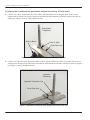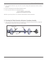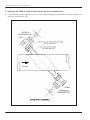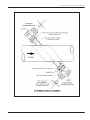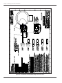
1
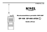
GE Measurement & Control Flow Standard and Extended Velocity Range T5 Flare Gas Transducers Installation Guide 916-117 Rev. C April 2013 GE Measurement & Control Standard and Extended Velocity Range T5 Flare Gas Transducers Installation Guide 916-117 Rev. C April 2013 www.ge-mcs.com ©2013 General Electric Company. All rights reserved. Technical content subject to change without notice. [no content intended for this page - proceed to next page] ii Contents Certification and Safety Statements . . . . . . . . . . . . . . . . . . . . . . . . . . . . . . . . . . . . . . . . . . . . . . . . . . . . . . . . . . . . . . . . . . . . vi Special Conditions for Safe Use . . . . . . . . . . . . . . . . . . . . . . . . . . . . . . . . . . . . . . . . . . . . . . . . . . . . . . . . . . . . . . . . .vii Chapter 1. Installing Pipe Nozzles 1.1 1.2 1.3 Introduction . . . . . . . . . . . . . . . . . . . . . . . . . . . . . . . . . . . . . . . . . . . . . . . . . . . . . . . . . . . . . . . . . . . . . . . . . . . . . . . . . . . . . . . . . . . .1 Bias 90° Installation . . . . . . . . . . . . . . . . . . . . . . . . . . . . . . . . . . . . . . . . . . . . . . . . . . . . . . . . . . . . . . . . . . . . . . . . . . . . . . . . . . . .1 1.2.1 Identifying and Checking the Nozzle Installation Kit Components. . . . . . . . . . . . . . . . . . . . . . . . . . . . . . . . . .2 1.2.2 Selecting and Marking the Pipe for Nozzle Locations. . . . . . . . . . . . . . . . . . . . . . . . . . . . . . . . . . . . . . . . . . . . . .4 1.2.3 Installing the First Welding Boss . . . . . . . . . . . . . . . . . . . . . . . . . . . . . . . . . . . . . . . . . . . . . . . . . . . . . . . . . . . . . . . . .8 1.2.4 Installing the First Nozzle . . . . . . . . . . . . . . . . . . . . . . . . . . . . . . . . . . . . . . . . . . . . . . . . . . . . . . . . . . . . . . . . . . . . . . . .9 1.2.5 Installing the Second Welding Boss . . . . . . . . . . . . . . . . . . . . . . . . . . . . . . . . . . . . . . . . . . . . . . . . . . . . . . . . . . . . 11 1.2.6 Installing the Second Nozzle . . . . . . . . . . . . . . . . . . . . . . . . . . . . . . . . . . . . . . . . . . . . . . . . . . . . . . . . . . . . . . . . . . . 13 1.2.7 Hot Tapping the Pipe . . . . . . . . . . . . . . . . . . . . . . . . . . . . . . . . . . . . . . . . . . . . . . . . . . . . . . . . . . . . . . . . . . . . . . . . . . 14 1.2.8 Cold Tapping the Pipe . . . . . . . . . . . . . . . . . . . . . . . . . . . . . . . . . . . . . . . . . . . . . . . . . . . . . . . . . . . . . . . . . . . . . . . . . 14 Tilted 45° Installation . . . . . . . . . . . . . . . . . . . . . . . . . . . . . . . . . . . . . . . . . . . . . . . . . . . . . . . . . . . . . . . . . . . . . . . . . . . . . . . . . 14 1.3.1 Identifying and Checking the Nozzle Installation Kit Components. . . . . . . . . . . . . . . . . . . . . . . . . . . . . . . . 15 1.3.2 Selecting and Marking the First Nozzle Location . . . . . . . . . . . . . . . . . . . . . . . . . . . . . . . . . . . . . . . . . . . . . . . . 16 1.3.3 Determining and Marking the Second Nozzle Location. . . . . . . . . . . . . . . . . . . . . . . . . . . . . . . . . . . . . . . . . . 18 1.3.4 Installing the First Welding Boss . . . . . . . . . . . . . . . . . . . . . . . . . . . . . . . . . . . . . . . . . . . . . . . . . . . . . . . . . . . . . . . 21 1.3.5 Installing the First Nozzle . . . . . . . . . . . . . . . . . . . . . . . . . . . . . . . . . . . . . . . . . . . . . . . . . . . . . . . . . . . . . . . . . . . . . . 23 1.3.6 Installing the Second Welding Boss and Nozzle . . . . . . . . . . . . . . . . . . . . . . . . . . . . . . . . . . . . . . . . . . . . . . . . . 25 1.3.7 Hot Tapping the Pipe . . . . . . . . . . . . . . . . . . . . . . . . . . . . . . . . . . . . . . . . . . . . . . . . . . . . . . . . . . . . . . . . . . . . . . . . . . 26 1.3.8 Cold Tapping the Pipe . . . . . . . . . . . . . . . . . . . . . . . . . . . . . . . . . . . . . . . . . . . . . . . . . . . . . . . . . . . . . . . . . . . . . . . . . 26 Chapter 2. Installing the Isolation Valve 2.1 2.2 2.3 Bias 90 Installation (for standard or extended range applications). . . . . . . . . . . . . . . . . . . . . . . . . . . . . . . . . . . . . . . 2.1.1 For 3 inch Flanges . . . . . . . . . . . . . . . . . . . . . . . . . . . . . . . . . . . . . . . . . . . . . . . . . . . . . . . . . . . . . . . . . . . . . . . . . . . . 2.1.2 For 2 inch Flanges . . . . . . . . . . . . . . . . . . . . . . . . . . . . . . . . . . . . . . . . . . . . . . . . . . . . . . . . . . . . . . . . . . . . . . . . . . . . Tilted 45° Installation (for standard range gas flow velocity up to 100 m/s (328 ft/s) applications) . . . . . . . . . 2.2.1 For 3 inch Flanges . . . . . . . . . . . . . . . . . . . . . . . . . . . . . . . . . . . . . . . . . . . . . . . . . . . . . . . . . . . . . . . . . . . . . . . . . . . . 2.2.2 For 2 inch Flanges . . . . . . . . . . . . . . . . . . . . . . . . . . . . . . . . . . . . . . . . . . . . . . . . . . . . . . . . . . . . . . . . . . . . . . . . . . . . Tilted 45° Installation (for extended range gas flow velocity up to 120 m/s (394 ft/s) for 3 inch valves). . . . . Standard and Extended Velocity Range T5 Flare Gas Transducers Installation Guide 27 27 27 27 27 27 28 iii Contents Chapter 3. Installing Transducer Assemblies 3.1 3.2 3.3 3.4 3.5 3.6 3.7 3.8 Introduction. . . . . . . . . . . . . . . . . . . . . . . . . . . . . . . . . . . . . . . . . . . . . . . . . . . . . . . . . . . . . . . . . . . . . . . . . . . . . . . . . . . . . . . . . . .31 Inserting Transducers Using a Low Pressure Insertion Mechanism - Common Steps . . . . . . . . . . . . . . . . . . . . . .31 3.2.1 Preparing for Installation . . . . . . . . . . . . . . . . . . . . . . . . . . . . . . . . . . . . . . . . . . . . . . . . . . . . . . . . . . . . . . . . . . . . . . .31 3.2.2 Mounting the Insertion Mechanism . . . . . . . . . . . . . . . . . . . . . . . . . . . . . . . . . . . . . . . . . . . . . . . . . . . . . . . . . . . . .32 Mounting the Bias 90 Insertion Mechanism Transducer Assembly . . . . . . . . . . . . . . . . . . . . . . . . . . . . . . . . . . . . . . .36 Inserting the Bias 90 Transducer into the Pipe . . . . . . . . . . . . . . . . . . . . . . . . . . . . . . . . . . . . . . . . . . . . . . . . . . . . . . . . . .39 Aligning the Transducers (for applications with gas flow velocity up to 100 m/s) . . . . . . . . . . . . . . . . . . . . . . . . . .41 Aligning the Transducers (for applications with gas flow velocity 120 m/s). . . . . . . . . . . . . . . . . . . . . . . . . . . . . . . .42 Mounting the Tilted 45 Insertion Mechanism Transducer Assembly . . . . . . . . . . . . . . . . . . . . . . . . . . . . . . . . . . . . . .45 3.7.1 Inserting the Tilted 45 Transducer into the Pipe . . . . . . . . . . . . . . . . . . . . . . . . . . . . . . . . . . . . . . . . . . . . . . . . .49 Connecting an XAMP . . . . . . . . . . . . . . . . . . . . . . . . . . . . . . . . . . . . . . . . . . . . . . . . . . . . . . . . . . . . . . . . . . . . . . . . . . . . . . . . . .52 Chapter 4. Specifications iv Standard and Extended Velocity Range T5 Flare Gas Transducers Installation Guide Preface Information Paragraphs • Note paragraphs provide information that provides a deeper understanding of the situation, but is not essential to the proper completion of the instructions. • Important paragraphs provide information that emphasizes instructions that are essential to proper setup of the equipment. Failure to follow these instructions carefully may cause unreliable performance. • Caution! paragraphs provide information that alerts the operator to a hazardous situation that can cause damage to property or equipment. • Warning! paragraphs provide information that alerts the operator to a hazardous situation that can cause injury to personnel. Cautionary information is also included, when applicable. Safety Issues WARNING! It is the responsibility of the user to make sure all local, county, state and national codes, regulations, rules and laws related to safety and safe operating conditions are met for each installation. Auxiliary Equipment Local Safety Standards The user must make sure that he operates all auxiliary equipment in accordance with local codes, standards, regulations, or laws applicable to safety. Working Area WARNING! Auxiliary equipment may have both manual and automatic modes of operation. As equipment can move suddenly and without warning, do not enter the work cell of this equipment during automatic operation, and do not enter the work envelope of this equipment during manual operation. If you do, serious injury can result. WARNING! Make sure that power to the auxiliary equipment is turned OFF and locked out before you perform maintenance procedures on the equipment. Qualification of Personnel Make sure that all personnel have manufacturer-approved training applicable to the auxiliary equipment. Personal Safety Equipment Make sure that operators and maintenance personnel have all safety equipment applicable to the auxiliary equipment. Examples include safety glasses, protective headgear, safety shoes, etc. Unauthorized Operation Make sure that unauthorized personnel cannot gain access to the operation of the equipment. Standard and Extended Velocity Range Flare Gas Transducer Installation Guide v Preface Environmental Compliance Waste Electrical and Electronic Equipment (WEEE) Directive GE Sensing & Inspection Technologies is an active participant in Europe’s Waste Electrical and Electronic Equipment (WEEE) take-back initiative, directive 2002/96/EC. The equipment that you bought has required the extraction and use of natural resources for its production. It may contain hazardous substances that could impact health and the environment. In order to avoid the dissemination of those substances in our environment and to diminish the pressure on the natural resources, we encourage you to use the appropriate take-back systems. Those systems will reuse or recycle most of the materials of your end life equipment in a sound way. The crossed-out wheeled bin symbol invites you to use those systems. If you need more information on the collection, reuse and recycling systems, please contact your local or regional waste administration. Visit http://www.gesensing.com/environment/weee.htm for take-back instructions and more information about this initiative. Certification and Safety Statements To maintain DEKRA certification, the transducer is provided with a ATEX and IECEx certified compression fitting and/or adapter of either thread M25 X 1.5 (material: brass) or ¾” NPT (material: 316 SS), both with tube size of 0.50” O.D. For example: Tyco part number 496SSGL34Ex ATEX certified under BASEEFA 08ATEX0327X and IECEx BAS08.0107X, Peppers adapter part number ARB/NP/075NPT/M20 ATEX certified under SIRA09ATEX1322X or SIRA09ATEX4323X and IECEx SIR09.0121X and reducer Capri part number 740724 ATEX certified under LCIO8ATEX6085X and IECEx LC018.0035X or equivalent parts. ATEX/IECEx certified enclosure, Type Ex d IIC. For example: International Metal Engineering PTE Limited (IME) Type 8080, 8075, 8066 or 7080 certified under SIRA 07ATEX1331U and IECEx SIR 07.0111U or equivalent that complies with EN 60079-0:2012/IEC 60079-0:2011 and EN 60079-1:2007/IEC 60079-1:2007. For example: Cortem SL-26.1N certified under CESI 03ATEX032U or equivalent. A certified metric-to-NPT adapter (material: brass) may be used in addition to the compression fitting in applicable configurations. Both fitting and adapter to comply with EN 60079-0:2012/ IEC 60079-0:2011 and EN 60079-0:2012/ IEC 60079-1:2007 for Ex d IIC. For electrical connection, the transducer must be mounted into a certified metal enclosure with type of protection flameproof enclosure “D”, complying with EN 60079-1:2007 and IEC 60079-1:2007 Ex d IIC. Measures must be taken to ensure a good electrical contact and to prevent the threads from self-loosening. The compression fitting is suitable for temperatures –60°C to 250°C. vi Standard and Extended Velocity Range Flare Gas Transducer Installation Guide Preface Special Conditions for Safe Use • The user/installer must take care that during operation with process temperatures lower than –40°C and higher than +60°C, the service temperature of the Ultrasonic Flow Transducers stays within –40°C to +60°C. A minimum distance of 8 inches (20 cm) shall be maintained between the process pipe and the compression gland. • The compression gland is suitable for operating temperatures to 250°C. With process temperatures up to 260°C, the user/installer shall take care (e.g. by measuring the temperature at this spot) that the temperature stays below the operating temperature of the compression gland. • To avoid electrical shock, be sure the transducer is mounted to a metal, electrically grounded pipe system. • To avoid an ignition hazard, protect the transducer from impact or friction. • Where the process temperature is below -25°C or exceeds 60°C, do not insulate the transducers or junction box. • The temperature class is based on the process temperature as shown in the product part number “EE” as shown below: Part Numbers T5-BB-CC-DD-EE-FF-EX BB Transducer Head 18 Straight Body / 180° 90 Right Angle / 90° 45 Oblique / 45° 17 Oblique / 174° CC Frequency 05 50 KHz 10 100 KHz 20 200 KHz 50 500 KHz DD = Tube length in inches, specified per application EE Process Temperature Range NT –55°C to +150°C HT –50°C to 260°C LT –220°C to +100°C FF Material Ti Titanium CP2 MN Monel 400 HC Hastelloy C276 SS SS316/304 Standard and Extended Velocity Range Flare Gas Transducer Installation Guide vii Preface viii Standard and Extended Velocity Range Flare Gas Transducer Installation Guide Chapter 1. Installing Pipe Nozzles Chapter 1. Installing Pipe Nozzles 1.1 Introduction Before the T5 transducers can be installed into the pipe, you will need to install pipe nozzles. Nozzles may be installed as part of a fabricated spoolpiece or by using the hot or cold tap process with a GE Sensing Nozzle Installation Kit. IMPORTANT: This procedure only applies if you are using a Nozzle Installation Kit. If you are tapping the pipe without using a Nozzle Installation Kit, refer to the supplied drawings in your shipment. This procedure is written and illustrated for installations on horizontal pipes; however, the procedure is the same for vertical pipe installations. This section describes how to install nozzles in the following configurations: 1. Bias 90o Installation a. Standard spacings of 10” and 9”, with both transducers facing straight at each other, are for gas velocity up to 100 m/s (328 ft/s) applications. This is the standard velocity range. b. Shorter spacing of 6.4”, with only the downstream transducer rotated 6° into the flow is for extended range gas velocity up to 120 m/s (394 ft/s) applications 2. Tilted 45o Installation a. Standard transducer face to face spacings, with both transducer body axes concentric and parallel to each other are for gas velocity up to 100 m/s (328 ft/s) applications. This is the standard velocity range. b. Shorter transducer face to face spacing of approximately 7.85”, with only the downstream transducer tilted 6° into the flow, is for extended range gas velocity up to 120 m/s (394 ft/s) applications. 1.2 Bias 90° Installation This procedure contains the following instructions: • identifying and checking the nozzle installation kit components • selecting and marking the pipe for nozzle locations • installing the first welding boss • installing the first nozzle • installing the second welding boss • installing the second nozzle • hot tapping the pipe Standard and Extended Velocity Range T5 Flare Gas Transducers Installation Guide 1 Chapter 1. Installing Pipe Nozzles 1.2.1 Identifying and Checking the Nozzle Installation Kit Components The Nozzle Installation Kit contains the materials listed below. Use Figure 1 below to help identify each component. • 2 Nozzles (if purchased) • 2 Welding Bosses • 1 Jig • 1 Alignment Plate (9 in., 10 in. or 6.4 in. spacing) • 1 Spacer Flange • 1 Threaded Rod (1 in. diameter), washer and nut IMPORTANT: You will need to supply eight 5/8” studs with two nuts each, or 3/4” studs with two nuts each; 5/8” studs for a 2” 150# flange, a 2” 300# flange or a 3” 150# flange, and 3/4” studs for a 3” 300# flange. Once you are familiar with each component, verify that the welding bosses and alignment plate shipped are for the required spacing and pipe size as described in the following steps. Welding Boss Nozzle Jig Spacer Flange Threaded Rod with Washer and Nut Alignment Plate Figure 1: Components for Nozzle Installation Kit 2 Standard and Extended Velocity Range Flare Gas Transducer Installation Guide Chapter 1. Installing Pipe Nozzles 1.2.1 Identifying and Checking the Nozzle Installation Kit Components (cont.) 1. Check the marking on the end of the welding boss. The pipe O.D. and the bias dimension (or spacing) are engraved on the boss as shown below. Typically, a. for flow velocity up to 100 m/s (328 ft/s) the 10 in. spacing is used on pipes 18 in. (450 mm) and larger; the 9 in. spacing is used on pipes 16 in. (400 mm) or on larger pipes when attenuating gases are present, and b. for up to 120 m/s (394 ft/s) flow velocity, the 6.4 in. spacing is used on pipes 14 in. (356 mm) or larger. Note: Bias dimension refers to the distance between the center of the nozzle location and the center line of the pipe. Pipe O.D. 36 in. 5 in. Bias Dimension or Spacing 3.4 in. Bias = 6.4 in. Spacing 4.5 in. Bias = 9 in. Spacing 5 in. Bias = 10 in. Spacing 2. Check the spacing between the holes on the alignment plate. The dimensions should correspond to the bias/spacing dimension on the welding boss. 12.73 in. 4.5 in. Bias (9 in. Spacing) 14.14 in. Bolt location shown for 150# rating. 5 in. Bias (10 in. Spacing) 9.05 in. 3.2 in. Bias (6.4 in. Spacing) Standard and Extended Velocity Range T5 Flare Gas Transducers Installation Guide 3 Chapter 1. Installing Pipe Nozzles 1.2.2 Selecting and Marking the Pipe for Nozzle Locations CAUTION! Correct nozzle alignment is critical to the successful operation of the flowmeter; therefore, all marking, positioning and welding operations must be carried out with the utmost attention to accuracy. Unless otherwise stated, dimensional positioning of the nozzles must be held to a tolerance of 1/16 in. (1.6 mm) relative to each other and with respect to the pipe centerline. The angular tolerance must be held to 1O. All hole cutting in process piping must be performed using hot tapping equipment. WARNING! BE SURE TO ADHERE TO ALL APPLICABLE SAFETY REGULATIONS. 1. For optimum performance, you should select a location that has at least 20 pipe diameters of straight, undisturbed pipe upstream and 10 pipe diameters of straight, undisturbed pipe downstream from the point of measurement. Undisturbed pipe means avoiding sources of turbulence such as flanges, elbows and tees; avoiding swirl; and avoiding disturbed flow profiles. Never install the flowmeter downstream of control valves, especially butterfly valves. If you cannot find a proper location, please consult with GE Sensing Flow Application engineering. 2. Use a center finder device to locate the center of the pipe. EYEBALLING IS NOT ADEQUATE FOR ACCURATE FLOW MEASUREMENT. 3. Lightly punch two marks approximately 16 in. apart on the top of the pipe running along the centerline. The two nozzle locations will fall between the two center punch marks. ~ 16 in. Top View 4. Spray the area between the two punch marks on the top of the pipe with a marking dye product. Using a metal edge, scribe a line between the two punch marks. 4 Standard and Extended Velocity Range Flare Gas Transducer Installation Guide Chapter 1. Installing Pipe Nozzles 1.2.2 Selecting and Marking the Pipe for Nozzle Locations (cont.) 5. Along the new scribe line, mark off a 10 in. length (or 9 in., or 6.4 in. depending on spacing) and scribe two perpendicular lines at least 10 in. in length as shown. 6. Along each perpendicular scribe line, lightly punch a mark at a distance of 5 in. (or 4.5 in., or 3.2 in.) from the center line, depending on the bias. Keep in mind that the distance along the arc of the pipe (L) from the pipe centerline is slightly greater. These marks pinpoint the centers for the nozzles. Refer to Table 1 on page 7 for arc distances for the most commonly used pipe sizes. If your pipe size is not shown in Table 1, use the equation in the figure on page 6 to calculate the arc distance. Standard and Extended Velocity Range T5 Flare Gas Transducers Installation Guide 5 Chapter 1. Installing Pipe Nozzles 1.2.2 Selecting and Marking the Pipe for Nozzle Locations (cont.) IMPORTANT: For 3.2 in.bias, the downstream port must be located on the right when a person is looking up against the flow (see the figure below). This convention is mandatory for the 6.4 in. spacing and is optional (not required) for the 10 in. or 9 in. spacing. Downstream Port Location for 3.2 in. bias Punch Marks Flow S L = Arc Length along pipe surface R Spacing A Calculate L as follows: L = 3.142 x R x A 180 Where A = Sin -1 ( ) S R R = Radius in inches S = Spacing in inches Bias in inches End View 6 Standard and Extended Velocity Range Flare Gas Transducer Installation Guide Chapter 1. Installing Pipe Nozzles 1.2.2 Selecting and Marking the Pipe for Nozzle Locations (cont.) Table 1: Calculated Arc Distances for Commonly Used Pipes Pipe O.D. Arc Distance 5 in. Bias 18 in. (450 mm) 5.301 in. 24 in. (600 mm) 5.157 in. 30 in. (750 mm) 5.098 in. 36 in. (900 mm) 5.067 in. 42 in. (1050 mm) 5.048 in. 4.5 in. Bias 16 in. (400 mm) 4.779 in. 18 in. (450 mm) 4.713 in. 24 in. (600 mm) 4.613 in. 30 in. (750 mm) 4.571 in. 36 in. (900 mm) 4.549 in. 42 in. (1050 mm) 4.536 in. 3.2 in. Bias 14 in. (350 mm) 3.323 in. 16 in. (400 mm) 3.292 in. 18 in. (450 mm) 2.272 in. 24 in. (600 mm) 3.239 in. 30 in. (750 mm) 3.225 in. 36 in. (900 mm) 3.217 in. 42 in. (1050 mm) 3.213 in. 7. Scribe a horizontal centerline (6 in. long) through each nozzle center location point parallel to the original centerline. Standard and Extended Velocity Range T5 Flare Gas Transducers Installation Guide 7 Chapter 1. Installing Pipe Nozzles 1.2.3 Installing the First Welding Boss 1. Each welding boss has four scribe marks indicating the center of the bias.Take one welding boss and line up its scribe marks with the horizontal and perpendicular scribe marks on the pipe as shown below. Make sure you position the boss on the pipe so that the contoured end of the boss matches the pipe arc (the shorter side of the boss should be closer to the original scribed pipe centerline). 2. Clamp the boss in place, using a pipe strap or equivalent, so that it cannot move during tack welding. 3. Check the boss alignment again, then tack weld the boss in each of the four grooves between the boss scribe marks. Make sure you keep the boss contour flush with the pipe contour during the entire tacking operation. The boss is constructed of carbon steel. 4. Check the alignment again. If the boss is misaligned by 0.02 in. (0.5 mm) or more, remove the boss, grind off the welds and reinstall. 8 Standard and Extended Velocity Range Flare Gas Transducer Installation Guide Chapter 1. Installing Pipe Nozzles 1.2.4 Installing the First Nozzle CAUTION! It is essential that the nozzles are set up and fixed in position using the jig and alignment plate provided, prior to welding the nozzle. 1. Screw the threaded rod into the boss that is welded onto the pipe. If necessary, remove the washer and nut from the threaded rod. Threaded Rod Welding Boss End View 2. Insert the pipe section of the jig (the key cut section) into the pipe section of the nozzle, and fasten the assembly using four nuts and bolts. Bolts Jig Nozzle Standard and Extended Velocity Range T5 Flare Gas Transducers Installation Guide 9 Chapter 1. Installing Pipe Nozzles 1.2.4 Installing the First Nozzle (cont.) 3. Slide the jig/nozzle assembly over the threaded rod, fitting the jig into the key cut end of the welding boss while aligning the contoured end of the nozzle to the pipe arc. Threaded Rod Jig Nozzle Welding Boss End View 4. Align the nozzle scribe marks with the pipe scribe marks and tighten the assembly in place using the 1-in. washer and nut. If slight misalignment occurs between the nozzle scribe marks and pipe scribe marks, loosen the four bolts holding the jig and nozzle assembly, and rotate the nozzle for the best alignment. Once it is aligned, retighten the four bolts. Washer and Nut End View 5. The jig, boss, and nozzle combination is designed to provide a 0.094 in. (2.4 mm) root gap between the beveled edge of the nozzle and the outside diameter of the pipe. If the 0.094 in. (2.4 mm) clearance does not exist all around, the nozzle must be removed and ground appropriately to provide the required clearance. If the root gap is larger than the 0.094 in. (2.4 mm) dimension evenly all around the nozzle, then suitably sized washers may be inserted between the jig and the nozzle in order to reduce the root gap dimension. WARNING! ONLY QUALIFIED PERSONNEL SHOULD WELD BOSSES AND NOZZLES, USING A SUITABLE ASME IX QUALIFIED WELDING PROCEDURE. ALL APPLICABLE SAFETY CODES SHOULD BE OBSERVED. 10 Standard and Extended Velocity Range Flare Gas Transducer Installation Guide Chapter 1. Installing Pipe Nozzles 1.2.4 Installing the First Nozzle (cont.) 6. Tack weld the nozzle to the pipe at four diametrically opposed points, each tack being approximately 0.2 in. (5 mm) in length. Allow to cool for 30 seconds between tacks. 7. Complete the root pass and subsequent filler passes as required. 8. Allow to cool, then remove the threaded rod, washer, nut, and jig. 1.2.5 Installing the Second Welding Boss 1. Bolt the jig to one end of the alignment plate using four bolts. Alignment Plate Jig Side View 2. Screw the threaded rod into the second boss. Insert the bolt/boss assembly into the jig key cut grooves and secure with the washer and nut on top. Threaded Rod Welding Boss Side View Washer and Nut to Secure Threaded Rod Welding Boss Side View 3. Remember to orient the boss in the jig to maintain the proper contour location to the pipe for installation. Standard and Extended Velocity Range T5 Flare Gas Transducers Installation Guide 11 Chapter 1. Installing Pipe Nozzles 1.2.5 Installing the Second Welding Boss (cont.) 4. Place the spacer flange on top of the welded nozzle and then mount the second end of the alignment plate on top of the spacer flange. Bolt into position using the remaining bolts. Spacer Flange Jig Welded Nozzle End View Top View 5. The second welding boss should now be positioned over the second nozzle location scribe marks. Align the boss scribe marks with the pipe scribe marks; then tighten all nuts securely. 6. Check the boss alignment again, then tack weld the boss in each of the four grooves between the boss scribe marks. 7. After tacking, check the boss alignment once more. If the boss is misaligned by 0.02 in. (0.5 mm) or more, remove the boss by grinding off the welds, and reinstall. 8. Remove the threaded rod and the jig. Leave the alignment plate bolted to the first nozzle, with the spacer flange sandwiched between them. 12 Standard and Extended Velocity Range Flare Gas Transducer Installation Guide Chapter 1. Installing Pipe Nozzles 1.2.6 Installing the Second Nozzle 1. Insert the jig into the second nozzle and position this assembly over the boss and under the alignment plate. Insert the threaded rod. Alignment Plate Spacer Flange Jig Nozzle End View 2. The jig, boss, and nozzle combination is designed to provide a 0.094 in. (2.4 mm) root gap between the beveled edge of the nozzle and the outside diameter of the pipe. If the 0.094 in. (2.4 mm) clearance does not exist all around, the nozzle must be removed and ground appropriately to provide the required clearance. If the root gap is larger than the 0.094 in. (2.4 mm) dimension, then suitably sized washers may be inserted between the jig and the nozzle in order to reduce the root gap dimension. 3. Secure the alignment plate by replacing the two sets of four bolts on both ends of the plate, and the washer and nut on the threaded rod. 4. Line up the nozzle scribe marks with the pipe scribe marks and tighten all the nuts. 5. Make sure the nozzle is still in alignment. WARNING! ONLY QUALIFIED PERSONNEL SHOULD WELD BOSSES AND NOZZLES, USING A SUITABLE ASME IX QUALIFIED WELDING PROCEDURE. ALL APPLICABLE SAFETY CODES SHOULD BE OBSERVED. 6. Tack weld the nozzle to the pipe at four diametrically opposed points, each tack being approximately 0.2 in. (5 mm) in length. Allow to cool for 30 seconds between tacks. 7. Proceed to complete the root pass and subsequent filler passes as required. 8. Allow to cool. 9. Remove all nuts and bolts, the alignment plate, jig, spacer flange and threaded rod. The completed installation should appear as shown below. Standard and Extended Velocity Range T5 Flare Gas Transducers Installation Guide 13 Chapter 1. Installing Pipe Nozzles 1.2.7 Hot Tapping the Pipe WARNING! HOT TAPPING SHOULD ONLY BE PERFORMED BY QUALIFIED PERSONNEL. FOLLOW ALL APPLICABLE CODE AND SAFETY PRACTICES DURING THESE PROCEDURES. For 3 in. Flanges: 1. Install 3 in. ANSI flanged isolation valves on both nozzles (full bore and 8 in. face to face 150# RF or 11.125 in. for 300# RF) with gasket and 5/8 in. or 3/4 in. diameter studs and nuts for 150# or 300# flange rating, respectively. Orient valve handles to minimize interference. 2. Hot tap holes in the pipe using a hot tap machine equipped with a 3/4 in. (19.05 mm) drill bit. Then use a coupon retaining hole saw to cut a hole with a diameter of 2.36 in. (60 mm) minimum to 2.875 in. (73 mm) maximum. For 2 in. Flanges: 1. Install 2 in. ANSI flanged isolation valves on both nozzles (full bore and 7 in. face to face 150# RF or 8.50 in. for 300# RF) with gasket and 5/8-in. diameter studs and nuts. Orient valve handles to minimize interference. 2. Hot tap holes in the pipe using a hot tap machine equipped with a 3/4 in. (19.05 mm) drill bit. Then use a coupon retaining hole saw to cut a hole with a diameter of 1.81 in. (46 mm) minimum to 1.89 in. (48 mm) maximum. 1.2.8 Cold Tapping the Pipe The procedure for cold tapping a pipe is the same as the hot tapping procedure, however, a valve is not necessary during the process. The hot tap medium can be applied directly to the nozzle. Valves will be added after the tapping is complete. 1.3 Tilted 45° Installation This procedure contains the following instructions: • Identifying and checking the nozzle installation kit components • Selecting and marking the first nozzle location • Determining and marking the second nozzle location • Installing the first welding Boss • Installing the first nozzle • Installing the second welding boss and nozzle • Hot tapping the pipe 14 Standard and Extended Velocity Range Flare Gas Transducer Installation Guide Chapter 1. Installing Pipe Nozzles 1.3.1 Identifying and Checking the Nozzle Installation Kit Components The nozzle kit consists of various components which you must identify and check as described in the following sub-sections. The Nozzle Installation Kit contains the materials listed below. Use Figure 2 below to help identify each component. 2 Nozzles (if purchased) 2 Welding bosses 1 Jig 1 Threaded rod (1 in. diameter), washer and nut IMPORTANT: You will need to supply eight 5/8” studs with two nuts each, or 3/4” studs with two nuts each (5/8” studs for a 2” 150# flange, a 2” 300# flange or a 3” 150# flange, and 3/4” studs for a 3” 300# flange). Welding Boss Nozzle Jig Threaded Rod with Washer and Nut Figure 2: Components for Nozzle Installation Kit Check the marking on the end of the welding boss. The pipe OD and the mounting angle are engraved on the boss as shown below. Pipe O.D. 10 in. 45° Mounting Angle Standard and Extended Velocity Range T5 Flare Gas Transducers Installation Guide 15 Chapter 1. Installing Pipe Nozzles 1.3.2 Selecting and Marking the First Nozzle Location CAUTION! Correct nozzle alignment is critical to the successful operation of the flowmeter; therefore, all marking, positioning and welding operations must be carried out with the utmost attention to accuracy. Unless otherwise stated, dimensional positioning of the nozzles must be held to a tolerance of 1/16 in. (1.6 mm) relative to each other and with respect to the pipe centerline. the angular tolerance must be held to 1O. All hole cutting in process piping must be performed using hot tapping equipment. 1. For optimum performance, you should select a location that has straight run pipeline at least 20 pipe diameters of straight, undisturbed pipe upstream and 10 pipe diameters of straight, undisturbed pipe downstream from the point of measurement. Undisturbed pipe means avoiding sources of turbulence such as valves, flanges, elbows; avoiding swirl; and avoiding disturbed flow profiles. 2. We recommend that you install the nozzles on a diameter as near as possible to the horizontal plane (i.e., 3 o’clock and 9 o’clock) for horizontal pipe. Note: If you cannot find a proper location, please consult with GE Sensing Flow Application engineering. 16 Standard and Extended Velocity Range Flare Gas Transducer Installation Guide Chapter 1. Installing Pipe Nozzles 1.3.2 Selecting and Marking the First Nozzle Location (cont.) 3. At the 3 o’clock position, center punch the pipe to mark the position for the center of the first nozzle. Side View 4. Spray this area with a marking dye product. Using a metal edge, scribe a vertical and a horizontal line (6 in. long) that intersect at the center punch mark. Side View Standard and Extended Velocity Range T5 Flare Gas Transducers Installation Guide 17 Chapter 1. Installing Pipe Nozzles 1.3.3 Determining and Marking the Second Nozzle Location 1. The position for the second nozzle is typically a distance equal to one pipe outside diameter along the pipe and located on the opposite side of the pipe (i.e., 180 ° around). Spray this area with a marking dye product. (For installation other than 45°, the distance is equal to the OD times the tangent of the install angle. 2. Due to the possible variation in outside diameter of the pipe, measure the outside diameter of the pipe at four location between the nozzle centers. Calculate the average outside diameter based on these measurements. D1 D2 D3 D4 Side View 3. Using a roll of polyester film (or equivalent), cut a strip of film at the width and length as follows: IMPORTANT: Ensure that the sides of the film are cut parallel to each other. • Width - equal to the average outside diameter calculated in Step 1 above. • Length - equal to 4 times the outside diameter of the pipe. Average O.D. 4 X O.D. 18 Standard and Extended Velocity Range Flare Gas Transducer Installation Guide Chapter 1. Installing Pipe Nozzles 1.3.3 Determining and Marking the Second Nozzle Location (cont.) 4. Wrap the strip of film around the pipe with one edge running along the vertical scribe line at the first nozzle location. Make sure the strip overlaps squarely around the pipe and mark the overlap position of the strip. This equals the circumference of the pipe. Overlap Mark Side View 5. Remove the strip of film and fold it as shown below to determine the position which is diametrically opposite the overlap position when the film is reapplied to the pipe. Overlap Mark Fold to Here 6. Mark the outside of the fold for reference. Mark the Edge Standard and Extended Velocity Range T5 Flare Gas Transducers Installation Guide 19 Chapter 1. Installing Pipe Nozzles 1.3.3 Determining and Marking the Second Nozzle Location (cont.) 7. Place the strip of film on the pipe again; this time, line up the overlap mark with the horizontal and vertical scribe lines. Again, make sure you wrap the strip of film squarely around the pipe. 8. The new position of the center of the second nozzle is now identified as the intersection of the fold line and the second edge of the strip of film. Center punch this location prior to removing the strip of film. 9. Remove the film. 10. Scribe vertical and horizontal lines (each 6 in. long) to intersect at the center-punch mark. Scribe Lines Side View 20 Standard and Extended Velocity Range Flare Gas Transducer Installation Guide Chapter 1. Installing Pipe Nozzles 1.3.4 Installing the First Welding Boss 1. Before welding the first boss, you must add another scribe line known as the oblique center line. The oblique center line compensates for the slope or oblique of the boss. The oblique center line is offset from the true center (vertical) scribe line marked earlier by a distance of “X,” which is dependent on the pipe outside diameter as follows: d2 X = D 2 – -----------------------------------------1 tan sin d D where, D = pipe outside diameter d = welding boss outside diameter (1.660 in.) Table 2 below shows values of X for various pipe sizes. Table 2: X Values for Various Pipe Sizes Pipe NPS (DN) O.D. X Dimensions 6 in. (150 mm) 6.625 in. 0.106 in. (2.69 mm) 8 in. (200 mm) 8.625 in. 0.081 in. (2.06 mm) 10 in. (250 mm) 10.750 in. 0.064 in. (1.62 mm) 12 in. (300 mm) 12.750 in. 0.054 in. (1.37 mm) 14 in. (350 mm) 14.000 in. 0.049 in. (1.24 mm) 2. Scribe the oblique center line on the pipe at the prescribed distance from the true center line. The oblique center line should be marked on the side of the true center line that is closer to the second nozzle location. True Center Line Oblique Center Line Side View Standard and Extended Velocity Range T5 Flare Gas Transducers Installation Guide 21 Chapter 1. Installing Pipe Nozzles 1.3.4 Installing the First Welding Boss (cont.) 3. Position the welding boss such that the four scribe lines on the welding boss are lined up with the horizontal scribe mark and the oblique center line on the pipe. Make sure you orient the boss as shown below. 4. Clamp the boss in place using a pipe strap or equivalent so that it cannot move during tack welding. 5. Check the boss alignment, then tack weld the carbon steel boss to the pipe in each of the four grooves between the boss scribe marks. 6. Remove the clamp and check the alignment again. If the boss is misaligned by 0.02 in. (0.5 mm) or more, remove the boss, grind off the welds and reinstall. 22 Standard and Extended Velocity Range Flare Gas Transducer Installation Guide Chapter 1. Installing Pipe Nozzles 1.3.5 Installing the First Nozzle IMPORTANT: It is essential that the nozzle is set up and fixed in position using the jig and 1-in. threaded rod provided, prior to welding the nozzle. 1. Screw the threaded rod into boss that is welded onto the pipe. If necessary, remove the washer and nut from the threaded rod. Threaded Rod Welded Boss 2. Slide the nozzle over the threaded rod, and align the contoured end of the nozzle so it matches the pipe arc. Then slide the jig over the threaded rod, fitting the jig into the welding boss. Jig Threaded Rod Nozzle Standard and Extended Velocity Range T5 Flare Gas Transducers Installation Guide 23 Chapter 1. Installing Pipe Nozzles 3. Align the jig and nozzle bolt holes and tighten the assembly in place, using the washer and nut. Washer and Nut Bolt Holes 4. The jig, boss, and nozzle combination is designed to provide a 0.094 in. (2.4 mm) root gap between the beveled edge of the nozzle and the outside diameter of the pipe. If the 0.094 in. (2.4 mm) clearance does not exist all around, the nozzle must be removed and ground appropriately to provide the required clearance. If the root gap is larger than the 0.094 in. (2.4 mm) dimension, then suitably sized washers may be inserted between the jig and the nozzle in order to reduce the root gap dimension. WARNING! ONLY QUALIFIED PERSONNEL SHOULD WELD BOSSES AND NOZZLES, USING A SUITABLE ASME IX QUALIFIED WELDING PROCEDURE. 5. Tack weld the nozzle to the pipe at four diametrically opposed points, each tack being approximately 0.6 in. (15 mm) in length. Allow to cool for 30 seconds between tacks. 6. Proceed to complete the root pass and subsequent filler passes as required. 7. Allow to cool, then remove the threaded rod, washer, nut, and jig. 24 Standard and Extended Velocity Range Flare Gas Transducer Installation Guide Chapter 1. Installing Pipe Nozzles 1.3.6 Installing the Second Welding Boss and Nozzle Install the second welding boss and nozzle at the required position as described in Installing the First Welding Boss and Installing the First Nozzle. The completed installation should appear as shown below. Standard and Extended Velocity Range T5 Flare Gas Transducers Installation Guide 25 Chapter 1. Installing Pipe Nozzles 1.3.7 Hot Tapping the Pipe Note: Hot tapping tilted 45° installation is possible only for the standard range (100 m/s, 328 ft/s) flow gas application. For the extended range (120 m/s, 394 ft/s) application, only the 4” pipe size can be hot topped. WARNING! HOT TAPPING SHOULD BE PERFORMED ONLY BY QUALIFIED PERSONNEL. FOLLOW ALL APPLICABLE CODE AND SAFETY PRACTICES DURING THESE PROCEDURES. For 3 in. Flanges: 1. Install 3 in. ANSI flanged isolation valves on both nozzles (full bore and 8 in. face to face 150# RF or 11.125 in. for 300# RF) with gasket and 5/8 in. or 3/4 in. diameter studs and nuts for 150# or 300# flange rating, respectively. Orient valve handles to minimize interference. 2. Hot tap holes in the pipe using a hot tap machine equipped with a 3/4 in. (19.05 mm) drill bit. Then use a coupon retaining hole saw to cut a hole with a diameter of 2.36 in. (60 mm) minimum. For 2 in. Flanges: 1. Install 2 in. ANSI flanged isolation valves on both nozzles (full bore and 7 in. face to face 150# RF or 8.50 in. for 300# RF) with gasket and 5/8-in. diameter studs and nuts. Orient valve handles to minimize interference. 2. Hot tap holes in the pipe using a hot tap machine equipped with a 3/4 in. (19.05 mm) drill bit. Then use a coupon retaining hole saw to cut a hole with a diameter of 1.81 in. (46 mm) minimum to 1.89 in. (48 mm) maximum. 1.3.8 Cold Tapping the Pipe Note: Cold tapping is the same as the hot top procedure for a standard range (100 m/s, 328 ft/s) flow gas meter. Cold tapping can be performed only before the isolation valve is installed, except for the 4 in. pipe size. This is due to the tilted downstream transducer/insertion mechanism and valve assembly. WARNING! COLD TAPPING SHOULD BE PERFORMED ONLY BY QUALIFIED PERSONNEL. FOLLOW ALL APPLICABLE CODE AND SAFETY PRACTICES DURING THESE PROCEDURES. For 3 in. Flanges: 1. Cold tap holes in the pipe using a hot tap machine equipped with a 3/4 in. (19.05 mm) drill bit. Then use a coupon retaining hole saw to cut a hole with a diameter of 2 7/8 in. (73 mm). 26 Standard and Extended Velocity Range Flare Gas Transducer Installation Guide Chapter 2. Installing the Isolation Valve Chapter 2. Installing the Isolation Valve Note: The following information demonstrates how to install an isolation valve onto a nozzle for applications using the flare gas insertion mechanism. 2.1 Bias 90 Installation (for standard or extended range applications) 2.1.1 For 3 inch Flanges Install 3 inch ANSI flanged isolation valves on both nozzles (full bore and 8 in. face to face 150# RF or 11.125 in. For 300# RF) with a gasket and 5/8 in. or 3/4 in. diameter studs and nuts for 150# or 300# flange rating, respectively. Orient the valve handles to minimize interference. Note: This installation of the isolation valve may have been accomplished already during the hot tapping operation. 2.1.2 For 2 inch Flanges Install 2 in. ANSI flanged isolation valves on both nozzles (full bore and 7 in. face to face 150# RF or 8 1/2 in. for 300# RF) with a gasket and 5/8 in. diameter studs and nuts. Orient the valve handles to minimize interference. Note: This installation of the isolation valve may have been accomplished already during the hot tapping operation. 2.2 Tilted 45° Installation (for standard range gas flow velocity up to 100 m/s (328 ft/s) applications) 2.2.1 For 3 inch Flanges Install 3 inch ANSI flanged isolation valves on both nozzles (full bore and 8 in. face to face 150# RF or 11.125 in. For 300# RF) with a gasket and 5/8 in. or 3/4 in. diameter studs and nuts for 150# or 300# flange rating, respectively. Orient the valve handles to minimize interference. Note: This installation of the isolation valve may have been accomplished already during the hot tapping operation. 2.2.2 For 2 inch Flanges Install 2 in. ANSI flanged isolation valves on both nozzles (full bore and 7 in. face to face 150# RF or 8 1/2 in. for 300# RF) with a gasket and 5/8 in. diameter studs and nuts. Orient the valve handles to minimize interference. Note: This installation of the isolation valve may have been accomplished already during the hot tapping operation. Standard and Extended Velocity Range T5 Flare Gas Transducers Installation Guide 27 Chapter 2. Installing the Isolation Valve 2.3 Tilted 45° Installation (for extended range gas flow velocity up to 120 m/s (394 ft/s) for 3 inch valves) Note: The upstream valve and transducers are installed without wedges, per normal installation procedures. To install the downstream valve assembly onto the spoolpiece, the following items are required (see Figure 3 below). Adjustment Screws 6° Wedge Bolt Spacer Bolt Spacer Hardware Gaskets Figure 3: Parts Used to Install a Valve Assembly Note: A 150# RF installation is shown. 1. Insert the four bolts into the flange holes. 2. With the Nut Side marking facing the pipe, place the split bolt spacer pieces behind the flange, over the bolts, with the thin ends corresponding to what will be the thickest side of the other wedge (see Figure 4 on the next page). Note: The wedge positions are based on the need to tilt the transducer 6° against the flow. 28 Standard and Extended Velocity Range T5 Flare Gas Transducers Installation Guide Chapter 2. Installing the Isolation Valve Flow Direction Nut Side Marking on Bolt Spacer Nozzle Face Marking on 6° Wedge Valve Face Marking on 6° Wedge Figure 4: Putting the Mounting Bolts, Bolt Spacers, Wedge and Gaskets in Place 3. With the Nozzle Face marking facing the pipe and the Valve Face marking facing outward, hold the gasket/ wedge/gasket in line with the insertion hole, and oriented in the required direction (see Figure 4 above). 4. While one person holds the gaskets and wedges in place, another person should line up the valve assembly mounting holes with the bolts already installed, push the valve assembly against the gasket/wedge/gasket, and install the washers and nuts to secure the valve assembly to the spoolpiece (see Figure 5 below). Nut Side Marking on Bolt Spacer Figure 5: Mounting the Valve Assembly Standard and Extended Velocity Range T5 Flare Gas Transducers Installation Guide 29 Chapter 2. Installing the Isolation Valve 2.3 Tilted 45° Installation (for extended range gas flow velocity of up to 120 m/s (394 ft/s) for 3 inch valves applications) (cont.) 5. Insert the two adjustment screws into the threaded holes on the wedge (see Figure 6 below) and use them to adjust/rotate the wedge until the scribe line is evenly positioned between the two bolts. Adjustment Screw Scribe Line Adjustment Screw Figure 6: Inserting the Adjustment Screws 6. When the wedge is positioned correctly, use wrenches to tighten the hardware and secure the components, then remove the adjustment screws. Figure 7: The Valve Wedges and Gaskets Installed Note: The upstream valve and transducers are installed without the wedge and bolt spacers, per normal installation procedures. 30 Standard and Extended Velocity Range T5 Flare Gas Transducers Installation Guide Chapter 3. Installing Transducer Assemblies Chapter 3. Installing Transducer Assemblies 3.1 Introduction Transducers and their holder assemblies are installed into a meter body. The meter body is a section of pipe that contains the ports where the transducer assemblies will be mounted. The meter body may be prefabricated or created by installing ports on the existing pipe. Transducers can be inserted into the pipes using a number of holder methods: • Low pressure insertion mechanism • Barrel holder • Flanged holder Note: This manual will describe the low pressure insertion mechanism type only. For other types please see the GE Transducer Installation Guide. 3.2 Inserting Transducers Using a Low Pressure Insertion Mechanism - Common Steps Note: The Insertion Mechanism is designed for manual (non-assisted) transducer insertion into operating or low pressurized pipes.The mechanism uses an isolation valve and a packing gland for sealing. Inserting the transducers into the pipe consists of the following: • Preparing for Installation • Mounting the Insertion Mechanism • Inserting the Transducer into the Pipe • Aligning the Transducers WARNING! THE MANUAL INSERTION MECHANISM SYSTEM IS FOR LOW PRESSURE APPLICATIONS [80 PSIG/6.5 BAR (absolute) OR LESS]. USE THE APPROPRIATE SAFETY PRECAUTIONS WHEN INSERTING OR WITHDRAWING THE INSERTION MECHANISM. 3.2.1 Preparing for Installation Before you begin, you should find an area where you can place the insertion mechanism upright without placing any weight on the transducer (e.g., a bench with a cutout large enough to slide the transducer through). You will need the following items for installation: • a packing tool (may be shipped with the electronics) • a gasket to place on the isolation valve • a straight edge ruler/scale • a tag to place on the isolation valve • bolts Standard and Extended Velocity Range T5 Flare Gas Transducers Installation Guide 31 Chapter 3. Installing Transducer Assemblies 3.2.2 Mounting the Insertion Mechanism 1. Before mounting the mechanism to the isolation valve you should familiarize yourself with its components (see the figure below): • junction box • barrel • packing gland • transducer Note: Explosion-proof boxes are not mounted on the end of the transducer when shipped. Junction Box Packing Gland Barrel Transducer (90° head shown) 32 Transducer (180° head shown) Standard and Extended Velocity Range T5 Flare Gas Transducers Installation Guide Chapter 3. Installing Transducer Assemblies 3.2.2 Mounting the Insertion Mechanism (cont.) 2. Visually inspect the transducer. Make sure the top compression fitting is not loose. IMPORTANT: The stop ring at the end of the barrel is supposed to be loose. DO NOT tighten the compression fitting or you could change the transducer alignment. Top Compression Fitting Four Bolts Stop Ring 3. Remove the four bolts that fasten the barrel to the packing gland. Standard and Extended Velocity Range T5 Flare Gas Transducers Installation Guide 33 Chapter 3. Installing Transducer Assemblies 3.2.2 Mounting the Insertion Mechanism (cont.) 4. Retract the barrel from the packing gland so that the transducer head is recessed in the packing gland. You will hear the stop ring click when the transducer is fully recessed. Compression Fitting hand tight 34 Standard and Extended Velocity Range T5 Flare Gas Transducers Installation Guide Chapter 3. Installing Transducer Assemblies 5. Visually inspect the mechanism. Make sure the transducer is recessed in the packing gland. Again, make sure the top compression fitting is secure and hand tight. Bias 90 Assembly with 90° Head Transducer recessed in packing gland Tilted Diameter Assembly with 180° Head Transducer recessed in packing gland Standard and Extended Velocity Range T5 Flare Gas Transducers Installation Guide 35 Chapter 3. Installing Transducer Assemblies 3.3 Mounting the Bias 90 Insertion Mechanism Transducer Assembly 1. Lift the gasket and insert the packing tool into the packing nut. Turning the packing tool clockwise, tighten the packing material so that the barrel will stay up without support. Gasket Barrel Packing Tool 2. Check and make sure the isolation valves are securely installed with gaskets and hardware, then place a gasket on the face of each isolation valve. Gasket Gasket Isolation Valve Isolation Valve Downstream Transducer location Upstream Transducer location Flow 36 Standard and Extended Velocity Range T5 Flare Gas Transducers Installation Guide Chapter 3. Installing Transducer Assemblies 3. For the Standard Velocity Range application, the upstream and downstream nozzle designations are interchangeable. The system is bi-directional. For the Extended Velocity Range application, the system is not bi-directional. Note which valve is designated upstream and downstream on the pipe. Identify the upstream and downstream insertion mechanism assemblies. The downstream assembly is labeled with a ring marked Downstream, located at the end of the assembly near the junction box. See the figure below. 4. Proceed with either the upstream or downstream assembly. 5. Lift the insertion mechanism by the barrel and place the insertion mechanism on the isolation valve. Downstream Transducer Assembly Identification Ring (on Extended Range version) Standard and Extended Velocity Range T5 Flare Gas Transducers Installation Guide 37 Chapter 3. Installing Transducer Assemblies 3.3 Mounting the Bias 90 Insertion Mechanism Transducer Assembly (cont.) 6. Line up the flange holes and bolt the packing gland to the isolation valve. Packing Tool Bolts 7. Using the packing tool, tighten the packing nut again so the nut is recessed. WARNING! THE PACKING MATERIAL MUST BE SECURELY PACKED BEFORE THE ISOLATION VALVE IS OPENED. 38 Standard and Extended Velocity Range T5 Flare Gas Transducers Installation Guide Chapter 3. Installing Transducer Assemblies 3.4 Inserting the Bias 90 Transducer into the Pipe 1. Before you open the isolation valve carefully check the following: • the barrel is pulled up as far as it can go; • all bolts are secure • the transducer head is recessed in the packing gland. Barrel Bolts Packing Gland WARNING! FOLLOW ALL APPLICABLE SAFETY CODES AND PRACTICES BEFORE OPENING THE ISOLATION VALVE. 2. Open the isolation valve. Standard and Extended Velocity Range T5 Flare Gas Transducers Installation Guide 39 Chapter 3. Installing Transducer Assemblies 3.4 Inserting the Bias 90 Transducer into the Pipe (cont.) 3. Placing your hands on top of the barrel, push the barrel/transducer down into the pipe so that the barrel flange and the packing gland flange meet. You may have to twist the barrel to get it moving. Place hands here 4. For this bias 90 configuration, orient the alignment marks on each barrel flange so that they are facing each other. The alignment mark is scribed on the top and outside of the flange. It will also be marked with paint. 40 Standard and Extended Velocity Range T5 Flare Gas Transducers Installation Guide Chapter 3. Installing Transducer Assemblies 5. Place two bolts into the flange in holes opposite each other, but not in the hole with the scribe mark. Hand tighten. Note: DO NOT insert the remaining bolts until instructed to do so in the following section. Bolts 6. Install the second insertion mechanism by repeating the steps in the two previous sections. After the second mechanism is installed proceed to the following section. 3.5 Aligning the Transducers (for applications with gas flow velocity up to 100 m/s) 1. Use a straight edge to line up the alignment marks. 2. Place the remaining bolts into the flanges and tighten securely. 3. Place a tag on the isolation valve stating the following: DO NOT OPERATE (CLOSE) WHEN TRANSDUCER IS INSERTED INTO PIPE. 4. Refer to your Startup Guide or User’s Manual to make transducer electrical connections. 5. This applies to both upstream and downstream assemblies equally. Standard and Extended Velocity Range T5 Flare Gas Transducers Installation Guide 41 Chapter 3. Installing Transducer Assemblies 3.6 Aligning the Transducers (for applications with gas flow velocity 120 m/s) Note: The downstream transducer is pre-set at the factory, in the barrel of the downstream insertion mechanism, to shift the signal direction 6° away from the upstream transducer signal. 1. Verify that the downstream transducer is located on the right when a person is looking up against the flow (see Figure 8 below). Contact a representative or the factory if the port locations do not follow this convention. Upstream Transducer Downstream Transducer Flow Figure 8: Mounting the Transducer Assemblies 2. Slide the end slot of the guide plate around the upstream transducer, and rotate the plate until the side slot is around the downstream transducer (see Figure 9 below). Align the transducer mark on the upstream barrel with the guide plate mark. Moderately tighten the upstream barrel bolts to maintain the alignment. Downstream Transducer Guide Plate Upstream Transducer Figure 9: Installing the Guide Plate 42 Standard and Extended Velocity Range T5 Flare Gas Transducers Installation Guide Chapter 3. Installing Transducer Assemblies 3. Place the cover plate on top of the guide plate and slide it as far as possible (until it is positioned around the upstream transducer) as shown in Figure 10 below. Then tighten the screws to secure it. Cover Plate Upstream Transducer W Figure 10: Installing the Cover Plate 4. Slide the locking collar down the downstream transducer to the cavity on top of the guide plate, align the 6° mark on the top of the collar with the line on the transducer (see Figure 11 below). Then tighten the collar set screws until it is secure around the transducer. Downstream Transducer 6° Mark Line on Transducer Tube Collar 6° Mark 0° Mark Figure 11: Locking Collar 6° Mark Aligned with Line on Transducer Tube Standard and Extended Velocity Range T5 Flare Gas Transducers Installation Guide 43 Chapter 3. Installing Transducer Assemblies 3.6 Aligning the Transducers (for applications with gas flow velocity 120 m/s) (cont.) 5. Check to see if the 0° mark on the side of the collar is aligned with the line on the guide plate. If they are not aligned, then loosen the nuts on top of the barrel and rotate the barrel/transducer assembly until the two lines are aligned (see Figure 12 below). Then retighten the nuts. Downstream Transducer Nuts on Barrel Collar 0° Mark Guide Plate Line Figure 12: Locking Collar 0° Mark Aligned with Guide Plate Line 6. Check to see if the line on the upstream transducer tube is aligned with the line on the cover plate. If they are not aligned, loosen the nuts on top of the barrel and rotate the barrel/transducer assembly until the two lines are aligned (see Figure 13 below). Retighten the nuts. Upstream Transducer Upstream Transducer Line Cover Plate Line W Figure 13: Upstream Transducer Mark Aligned with Cover Plate Line 44 Standard and Extended Velocity Range T5 Flare Gas Transducers Installation Guide Chapter 3. Installing Transducer Assemblies 7. Upon completion of the above steps, remove the cover plate, locking collar and guide plate from the transducer assemblies. 8. Place the remaining bolts into the flanges and tighten securely. 9. Place a tag on the isolation valve stating the following: DO NOT OPERATE (CLOSE) WHEN TRANSDUCER IS INSERTED INTO PIPE 10. Refer to your Startup Guide or User’s Manual to make transducer electrical connections. 3.7 Mounting the Tilted 45 Insertion Mechanism Transducer Assembly 1. Lift the gasket and insert the packing tool into the packing nut. Turning the packing tool clockwise, tighten the packing material so that the barrel will stay up without support. Packing Tool Gasket Barrel Standard and Extended Velocity Range T5 Flare Gas Transducers Installation Guide 45 Chapter 3. Installing Transducer Assemblies 3.7 Mounting the Tilted 45 Insertion Mechanism Transducer Assembly (cont.) 2. Check and make sure the isolation valves are securely installed with gaskets and hardware, then place a gasket on the face of each isolation valve. 46 Standard and Extended Velocity Range T5 Flare Gas Transducers Installation Guide Chapter 3. Installing Transducer Assemblies Standard and Extended Velocity Range T5 Flare Gas Transducers Installation Guide 47 Chapter 3. Installing Transducer Assemblies 3.7 Mounting the Tilted 45 Insertion Mechanism Transducer Assembly (cont.) 3. For the Standard Velocity Range application, the upstream and downstream nozzle designations are interchangeable. The system is bi-directional. For the Extended Velocity Range application, the system is not bi-directional. Note which valve is designated upstream and downstream on the pipe. Identify the upstream and downstream insertion mechanism assemblies. The downstream assembly is labeled with a ring marked Downstream, located at the end of the assembly near the junction box. See the figure below. 4. Proceed with either the upstream or downstream assembly. 5. Lift the insertion mechanism by the barrel and place the insertion mechanism on the isolation valve. Downstream Transducer Assembly Identification Ring (on Extended Range Version) 6. Line up the flange holes and bolt the packing gland to the isolation valve. Bolts 48 Standard and Extended Velocity Range T5 Flare Gas Transducers Installation Guide Chapter 3. Installing Transducer Assemblies 3.7 Mounting the Tilted 45 Insertion Mechanism Transducer Assembly (cont.) 7. Using the packing tool, tighten the packing nut again so the nut is recessed. WARNING! THE PACKING MATERIAL MUST BE SECURELY PACKED BEFORE THE ISOLATION VALVE IS OPENED. Packing Tool 3.7.1 Inserting the Tilted 45 Transducer into the Pipe 1. Before you open the isolation valve carefully check the following: • the barrel is pulled as far up as it can go; • all bolts are secure • the transducer head is recessed in the packing gland. Bolts Barrel Packing Gland Standard and Extended Velocity Range T5 Flare Gas Transducers Installation Guide 49 Chapter 3. Installing Transducer Assemblies WARNING! FOLLOW ALL APPLICABLE SAFETY CODES AND PRACTICES BEFORE OPENING THE ISOLATION VALVE. 2. Open the isolation valve. 3. Placing your hands at the end of the barrel, push the barrel/transducer into the pipe so that the barrel flange and the packing gland flange meet. You may have to twist the barrel to get it moving. Place hands here 4. Place the bolts into the flange joining the barrel flange to the packing gland flange. 5. Tighten the bolts securely. Bolts 50 Standard and Extended Velocity Range T5 Flare Gas Transducers Installation Guide Chapter 3. Installing Transducer Assemblies 3.7.1 Inserting the Tilted 45 Transducer into the Pipe (cont.) 6. Install the second insertion mechanism by repeating the steps in the previous sections. Confirm that the downstream transducer assembly is in the downstream port and the upstream assembly is in the upstream port. 7. Place a tag on the isolation valve stating the following: DO NOT OPERATE (CLOSE) WHEN TRANSDUCER IS INSERTED INTO PIPE. 8. Refer to your Startup Guide or User’s Manual to make transducer electrical connections. 9. This applies to both upstream and downstream assemblies equally. Standard and Extended Velocity Range T5 Flare Gas Transducers Installation Guide 51 Chapter 3. Installing Transducer Assemblies 3.8 Connecting an XAMP The following section explains how to correctly install and assemble an XAMP into a transducer junction box. It applies to all three possible junction box options (refer to drawing #752-063, Figure 22 on page 56), despite one junction box being used as an example in the steps below. 1. Place a 3/4” NPT compression fitting on the stem of the transducer closest to the BNC end. 2. Torque the fitting into one of the 3/4” NPT ports of the junction box with at least 5 threads engaged. Once the fitting is torqued into place, ensure that the BNC head of the transducer extends slightly past the ground screw bosses as shown below: Figure 14: Torquing Reducer into NPT Port 3. If the BNC head extends too far into the junction box, it will make the assembly more difficult by reducing the amount of area needed to properly store the excess cable. If the BNC head is not positioned approximately where it is pictured in the image above, loosen the compression fitting and adjust the transducer. Tighten the compression fitting after this is completed. 4. Torque the cable gland provided coming from the electronics main housing into the other 3/4” NPT port until there are at least 5 threads of engagement. Figure 15: Torquing the Cable Gland 52 Standard and Extended Velocity Range T5 Flare Gas Transducers Installation Guide Chapter 3. Installing Transducer Assemblies 3.8 Connecting an XAMP (cont.) With the transducer and the cable gland assembled, the junction box should now resemble Figure 16 below: Figure 16: Assembled Transducer and Cable Gland 5. First connect the right angle male BNC plug to the exposed BNC cable from the cable gland assembly as shown in Figure 17 below. Figure 17: Connecting BNC Plug to Cable Standard and Extended Velocity Range T5 Flare Gas Transducers Installation Guide 53 Chapter 3. Installing Transducer Assemblies 3.8 Connecting an XAMP (cont.) 6. Connect the female BNC plug of the XAMP to the male BNC transducer head as shown in Figure 18 below: Figure 18: Female Plug to Male BNC Head 7. Wrap the extra length of cable around the perimeter of the junction box such that the BNC heads do not rest on other cables or on each other. An image of this can be seen in Figure 19 below. Figure 19: BNC Heads 54 Standard and Extended Velocity Range T5 Flare Gas Transducers Installation Guide Chapter 3. Installing Transducer Assemblies 3.8 Connecting an XAMP (cont.) 8. Place the XAMP body into the junction box, resting the puck gently on the cables below it. Ensure that the cables of the XAMP rest naturally according to the slant at which they exit the epoxy (to reduce stress and strain on the joint). The XAMP should remain still, and the cap of the junction box should rotate freely around the XAMP. Figure 20: Junction Box Cap 9. Place the lid of the junction box over top of the XAMP and tighten the lid until the unit is closed and secure. Engage the set screw to prevent it from being tampered or removed. Figure 21: Set Screw of Junction Box To disconnect or uninstall the XAMP from the assembly, users can reverse the procedures above. Standard and Extended Velocity Range T5 Flare Gas Transducers Installation Guide 55 1180 GE Sensing 1100 Technology Park Dr. Billerica, MA 01821 USA Chapter 3. Installing Transducer Assemblies Figure 22: Transducer Arrangement (dwg. #752-063, rev. L) 56 Standard and Extended Velocity Range T5 Flare Gas Transducers Installation Guide Chapter 4. Specifications Chapter 4. Specifications Transducer Table 3: T5 Transducer Specifications T5 Specification Designation Hazardous area applications; flare gas, hydrocarbon gases, saturated steam. Installation Type Wetted Material Standard: Titanium Optional: 316SS, Monel or Hastelloy Field Mounting Flowcell, hot or cold tap Process Connection 1.5 in. to 3 in. (40 mm to 80 mm) flanged Holder Type Insertion mechanism Holder Ratings 150#, 300#, 600# Operating Frequency Standard: 100 kHz Optional: 50 kHz and 200 kHz Pressure Range 0 to 2700 psig Electrical Rating 200 V peak-to-peak, 5 mA Ambient Temperature Range Europe:–40° to +140°F (–40° to +60°C) North America: –40° to +140°F (–40° to +60°C) Process Temperature Range –364° to +500°F (–220° to +260°C) North American Certifications Explosion proof European / International Certifications - Flameproof Class I, Division 1, Group C, D Class II, Class III, Division 1, Group E, F, G II 2 G Ex d IIC T6...T2 Gb (T code dependent on Process Temperature) Tamb –40° to +140oF (–40° to +60oC) KEMA 01ATEX2045X: IECEx KEM09.0009X Standards used: EN 60079-0:2012, EN 60079-1:2007, IEC 60079-0:2011, IEC 60079-1:2007, Ed. 6. North American Certifications Weatherproof European / International Certifications - Weatherproof IP66, TYPE 4X 200Vpp, 5mA IP 66 Standard and Extended Velocity Range T5 Flare Gas Transducers Installation Guide 57 Chapter 4. Specifications [no content intended for this page - proceed to next page] 58 Standard and Extended Velocity Range T5 Flare Gas Transducers Installation Guide Warranty Warranty Each instrument manufactured by GE Sensing is warranted to be free from defects in material and workmanship. Liability under this warranty is limited to restoring the instrument to normal operation or replacing the instrument, at the sole discretion of GE Sensing. Fuses and batteries are specifically excluded from any liability. This warranty is effective from the date of delivery to the original purchaser. If GE Sensing determines that the equipment was defective, the warranty period is: • one year from delivery for electronic or mechanical failures • one year from delivery for sensor shelf life If GE Sensing determines that the equipment was damaged by misuse, improper installation, the use of unauthorized replacement parts, or operating conditions outside the guidelines specified by GE Sensing, the repairs are not covered under this warranty. The warranties set forth herein are exclusive and are in lieu of all other warranties whether statutory, express or implied (including warranties or merchantability and fitness for a particular purpose, and warranties arising from course of dealing or usage or trade). Return Policy If a GE Sensing instrument malfunctions within the warranty period, the following procedure must be completed: 1. Notify GE Sensing, giving full details of the problem, and provide the model number and serial number of the instrument. If the nature of the problem indicates the need for factory service, GE Sensing will issue a RETURN AUTHORIZATION NUMBER (RAN), and shipping instructions for the return of the instrument to a service center will be provided. 2. If GE Sensing instructs you to send your instrument to a service center, it must be shipped prepaid to the authorized repair station indicated in the shipping instructions. 3. Upon receipt, GE Sensing will evaluate the instrument to determine the cause of the malfunction. Then, one of the following courses of action will then be taken: • If the damage is covered under the terms of the warranty, the instrument will be repaired at no cost to the owner and returned. • If GE Sensing determines that the damage is not covered under the terms of the warranty, or if the warranty has expired, an estimate for the cost of the repairs at standard rates will be provided. Upon receipt of the owner’s approval to proceed, the instrument will be repaired and returned. Standard and Extended Velocity Range T5 Flare Gas Transducers Installation Guide 59 Warranty [no content intended for this page - proceed to next page] 60 Standard and Extended Velocity Range T5 Flare Gas Transducers Installation Guide GE Sensing DECLARATION OF CONFORMITY DOC-0028, Rev. E GE Sensing 1100 Technology Park Drive Billerica, MA 01821 USA We, declare under our sole responsibility that the Models T3, T5, T8, T11, T14 and T17 Wetted Ultrasonic Flow Transducers Models BWT, p/n 533-322 and p/n 533-323 Buffered Ultrasonic Flow Transducers to which this declaration relates, are in conformity with the following standards: • IEC 60079-0: 2009 • IEC 60079-1: 2007 • EN 60079-0: 2012 • EN 60079-1: 2007 • EN 50281-1-1: 1998 • II 2 G Ex d IIC T6 Gb - T3: KEMA06ATEX0052, T5: KEMA01ATEX2045X, T8: KEMA02ATEX2283X, T11: KEMA02ATEX2252, T14: KEMA04ATEX2054X, T17: KEMA01ATEX2045X BWT, 533-322, 533-323: KEMA01ATEX2051; IEC Ex KEM09.0010 (DEKRA Certification B.V., Ultrechtseweg, 310 Arnhem, The Netherlands - NoBo 0344) • EN 61326-1: 2006, Class A, Table 2, Industrial Locations • EN 61326-2-3: 2006 • EN 61010-1: 2001, Overvoltage Category II, Pollution Degree 2 Other standards used: • EN 50014: 1997 + A1, A2 • EN 50018: 2000 following the provisions of the 2004/108/EC EMC, 2006/95/EC Low Voltage and 94/9/EC ATEX Directives. Where products were initially assessed for compliance with the Essential Health and Safety Requirements of the ATEX Directive 94/9/EC using earlier harmonized standards, a subsequent review has determined that “technical knowledge” is unaffected by the current harmonized standards listed above. The units listed above and any ancillary equipment supplied with them do not bear CE marking for the Pressure Equipment Directive, as they are supplied in accordance with Article 3, Section 3 (sound engineering practices and codes of good workmanship) of the Pressure Equipment Directive 97/23/EC for DN<25. Billerica - November 2011 Issued Mr. Gary Kozinski Certification & Standards, Lead Engineer GE Sensing ATEX COMPLIANCE GE Infrastructure Sensing, Inc. 1100 Technology Park Drive Billerica, MA 01821-4111 U.S.A. We, as the manufacturer, declare under our sole responsibility that the product Type T5 Ultrasonic Flow Transducer to which this document relates, in accordance with the provisions of ATEX Directive 94/9/EC Annex II, meets the following specifications: 1180 II 2 G Ex d IIC T6 . . . T2 Gb KEMA01ATEX2045X -40°C to +60°C Furthermore, the following additional requirements and specifications apply to the product: • Having been designed in accordance with EN 60070-0 and EN 60079-1, the product meets the fault tolerance requirements of electrical apparatus for category “d”. • The product is an electrical apparatus and must be installed in the hazardous area in accordance with the requirements of the EC Type Examination Certificate. The installation must be carried out in accordance with all appropriate international, national and local standard codes and practices and site regulations for flameproof apparatus and in accordance with the instructions contained in the manual. Access to the circuitry must not be made during operation. • Only trained, competent personnel may install, operate and maintain the equipment. • The product has been designed so that the protection afforded will not be reduced due to the effects of corrosion of materials, electrical conductivity, impact strength, aging resistance or the effects of temperature variations. • The product cannot be repaired by the user; it must be replaced by an equivalent certified product. Repairs should only be carried out by the manufacturer or by an approved repairer. • The product must not be subjected to mechanical or thermal stresses in excess of those permitted in the certification documentation and the instruction manual. • The product contains no exposed parts which produce surface temperature infrared, electromagnetic ionizing, or non-electrical dangers. • Installation Instructions: Install per manual 916-117. CERT-ATEX-D (Rev. August 2004) Customer Support Centers U.S.A. The Boston Center 1100 Technology Park Drive Billerica, MA 01821 U.S.A. Tel: 800 833 9438 (toll-free) 978 437 1000 E-mail: [email protected] Ireland Sensing House Shannon Free Zone East Shannon, County Clare Ireland Tel: +353 61 61470291 E-mail: [email protected] An ISO 9001-2008 Certified Company www.ge-mcs.com/en/about-us/quality.html www.ge-mcs.com ©2013 General Electric Company. All rights reserved. Technical content subject to change without notice. 916-117 Rev. C