1
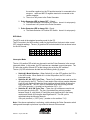
Pulse Generator
User Manual
Introduction
The MCM Pulse Generator (PG) is used in conjunction with the WaveForm Analyzer
(WFA) to measure ON/OFF (soil and pipe IR drop free) pipe-to-soil potentials on
impressed current cathodic protection rectifiers. The PG has two modes of operation:
WFA Mode: The WFA Mode is the normal mode of operation. It is used to
measure the ON/OFF pipe-to-soil potentials with the WFA;
Interrupter Mode: In the interrupter mode, the PG functions as a standard
current interrupter with a variety of user selectable timing cycles.
WaveForm Analyzer/Pulse Generator System
Technical Discussion
The WFA is a microprocessor based handheld voltmeter. It uses a complex computer
algorithm to measure the ON/OFF (IR drop free) pipe-to-soil (P/S) potentials in
impressed current cathodic protection systems. In order for the WFA to accurately
calculate the OFF potential, a PA must be installed in each rectifier or current source
affecting the location where the P/S measurement is being made.
The PG interrupts the output rectifier in which it is installed on a precise timing cycle.
This interruption generates the precisely timed zero current pulse which is required by
the WFA to accurately calculate the OFF potential. Pulse Generators are low cost and
designed to be permanently installed in the rectifier, turned on, and left to operate
permanently.
As stated earlier, the WFA uses a complex algorithm or set of computer instructions to
calculate the ON/OFF P/S potential. The algorithm consists of the following steps:
1. The WFA captures a digital picture of the P/S potential waveform by recording
thousands of voltage readings on the waveform;
2. Digital signal processing techniques are used to filter out any induced AC or 60cycle noise within the waveform;
3. The ON potential reading is calculated;
4. The IR drop contribution from the six (6) Pulse Generators having the greatest
influence on the reading is determined by analyzing the zero current pulses from
the Pulse Generators;
5. Once the total drop contribution is known, the OFF potential reading is calculated
by subtracting the IR drop from the ON value.
Note: The WFA algorithm includes the IR drop contribution from the six (6) rectifiers (or
up to six (6)) having the largest IR drop. To date, in extensive field-testing conducted on
numerous cross-country pipelines, tank farms, and industrial facilities, no location has
been found where more than five (5) rectifiers were influencing the reading.
Revised – July 30, 2001 RE
2
Installing the Pulse Generator
General Installation
The design of the Pulse Generator permits it to be permanently installed in a cathodic
protection rectifier. Its small size (6.5” x 5” x 2.5”) allows for easy installation inside most
existing rectifiers.
The following guidelines should be followed when installing the PG:
1. The PG should be installed vertically, i.e. the heat sink cooling fins should be
vertical, especially when used with rectifiers having a current output above 40
amps. Mounting the PG vertically insures maximum heat dissipation;
2. The design of the PG permits it to be installed within the rectifier cabinet. If there
is not sufficient room within the rectifier cabinet, the PG should be mounted in a
separate waterproof enclosure;
3. There should be sufficient airflow around the PG, especially if the rectifier is
operating at or above 40 amps of current output;
4. The PG should be energized (AC power should be applied) first, and then the
rectifier should be energized;
5. The RED LED on the Pulse Generator printed circuit board is lit when the PG is
on or is conducting current.
AC Power
The Pulse Generator requires either 110 volt or 220 volt / 60-hertz single phase AC
power for proper operation. A four (4) foot long, three (3) conductor AC power cable is
supplied with the PG. The three (3) conductors are colored coded as follows:
•
•
•
BLACK – AC power hot wire;
WHITE – AC power neutral wire;
GREEN – Safety ground wire. The safety ground is connected to the Pulse
Generator case (BLACK heat sink).
The RED slide switch on the PG is used to select the AC supply voltage. The slide
switch should show 115V when a 110/115-volt AC supply is used. The slide switch
should show 230V when a 220/230-volt AC supply is used. Note: Before applying AC
power, make sure the slide switch is set to the actual supply voltage.
The Pulse Generator will be damaged if the supply voltage selector switch is not set to
the actual supply voltage.
The PG draws less than .6 watts from the AC supply. The PG will function properly
when the supply voltage varies ± 15% from the rated AC supply voltage.
AC power should be supplied to the PG before the rectifier is turned on. (Turn on the PG
FIRST, and then turn on the rectifier.)
Revised – July 30, 2001 RE
3
Rectifier Connections
The Pulse Generator must be installed in series … in either the positive or negative
output leg of the rectifier. Two lugs are provided on the PG for the connection into one
of the rectifier output legs. These lugs will accept up to one #6 AWG cable. The lugs
are marked with either a plus (+) sign or a negative (-) sign on the printed circuit board
beneath the lugs. The PG only allows DC current to flow from the positive (+) lug to the
negative (-) lug.
When connecting the PG in the rectifier’s positive leg (rectifier anode connection), the
PG positive terminal is connected to the rectifier’s positive cable and the PG negative
terminal is connected to the anode header cable.
When installing the Pulse Generator, MCM recommends that it be installed on the inside
of the rectifier and wired so that the PG may take advantage of the lightning protection
circuitry on the rectifier’s DC output. Any lightning induced surges on either the structure
cable or anode cable should be clamped by the rectifier lightning arrestor prior to being
clamped by the voltage surge suppression circuitry on the PG.
Mode Selection Switch
The ten-position slide DIPswitch on the PG is used to select the two (2) PG operating
modes.
Care and Maintenance
The Pulse Generator has been designed to operate reliably and accurately while
installed in standard cathodic protection rectifiers. While no specific regular
maintenance procedures are required, MCM recommends the following guidelines be
followed:
1. While the PG printed circuit boards have been conformal coated for
environmental protection, the PG should not be exposed to direct moisture. The
design of the PG allows it to be mounted within a waterproof enclosure.
2. The PG should be mounted so the heat sink cooling fins are vertical. This will
insure maximum heat dissipation from the heat sink.
Troubleshooting
A number of possible PG problems and suggested remedies are listed below:
1. No Rectifier Current Output – There will be no current output from the
rectifier if:
a. The Pulse Generator polarity has been reversed when connected to
the rectifier. When the PG is wired into the positive rectifier leg, the
PG positive terminal goes to the rectifier and the PG negative terminal
is connected to the anode header cable. When the PG is wired into
Revised – July 30, 2001 RE
4
the rectifier negative leg, the PG positive terminal is connected to the
structure cable and the PG negative terminal is connected to the
rectifier negative;
b. There is no AC power to the Pulse Generator.
2. Pulse Generator LED is always OFF – Check:
a. The Mode Selection 10 Position DIP Switch. Insure it is set properly;
b. Insure there is AC power to the Pulse Generator.
3. Pulse Generator LED is always ON – Check:
a. The Mode Selection 10 Position DIP Switch. Insure it is set properly.
WFA Mode
The WFA mode is the standard operating mode for the PG.
The PG must be in the WFA mode in order for the WaveForm Analyzer to take correct
OFF potential readings. The ten (10) position DIP switch should be set as shown below
for the WFA mode:
| | | | | | |
ON
OFF | | |
SW 1 2 3 4 5 6 7 8 9 10
Interrupter Mode
The ten (10) position DIP switch may be used to set the Pulse Generator in the current
interrupter mode. In this mode, the PG functions as a standard current interrupter. The
PG turns the rectifier ON and OFF at the timing cycle set by the DIP switches.
The ten (10) DIP switches are divided into the following three (3) groups:
•
•
•
Switch #1: Mode Selection – When Switch #1 is in the OFF position, the PG is
in the WFA mode. When Switch #1 is in the ON position, the PG is in the
interrupter mode;
Switches #2 - #6: OFF Cycle Time – These five (5) switches are used to set the
off cycle time for the PG. The five (5) are used to form a binary number between
0 and 32, with Switch #2 being the most significant bit and Switch #6 being the
least significant bit. The OFF cycle is calculated using the following formula:
OFF cycle (seconds) = ((number on the switches 2-6) + 1)/2
Switches #7 - #10: ON Cycle Time – These four (4) switches are used to set
the on cycle time for the PG. The four (4) switches form a binary number
between 0 and 16, with Switch # 7 being the most significant bit in the binary
number and Switch #10 being the least significant bit. The ON cycle is
calculated using the following formula:
ON cycle (seconds) = (OFF cycle) * (number on the switches 7-10)
Note: If the above explanation is confusing, a table showing the Pulse Generator switch
settings and interrupter cycle times is provided at the end of this manual.
Revised – July 30, 2001 RE
5
For additional information or technical assistance, contact the M. C. Miller Co., Inc.
M. C. Miller Co., Inc.
3020 Aviation Blvd.
Vero Beach, FL 32960
Tel: 772-794-9448
Fax: 772-794-9908
[email protected]
www.mcmiller.com
Mode Selection Switch Summary Table
SW1
|
|
|
|
|
|
|
|
|
|
|
|
|
|
|
0
|
SW2
0
0
0
0
0
0
0
0
0
0
0
0
|
|
|
0
0
SW3
0
0
0
|
|
|
|
0
0
0
0
|
|
|
|
0
0
SW4
0
0
|
|
|
|
|
0
0
|
|
|
|
|
|
|
0
SW5
0
|
|
|
|
|
|
|
|
|
|
|
|
|
|
|
0
SW6
|
|
|
|
|
|
|
|
|
0
|
0
0
|
|
|
0
SW7
0
0
0
0
0
0
0
0
|
0
0
0
0
0
|
|
|
SW8
0
0
0
0
0
0
|
|
0
0
0
0
0
0
|
|
|
SW9
0
0
0
0
|
|
|
|
|
|
|
0
0
|
|
|
|
SW10
|
|
|
|
0
|
|
|
|
|
|
|
|
0
|
|
|
OFF
ON
1sec
1sec
2sec
2sec
4sec
4sec
8sec
8sec
8sec
16sec
8sec
24sec
8sec
56sec
8sec
120sec
1.5sec
4sec
2sec
5.5sec
3.5sec 9.5sec
3.5sec 3.5sec
16sec
16sec
16sec
32sec
16sec 240sec
xxxxx
xxxxx
Always On
MODE
INTER
INTER
INTER
INTER
INTER
INTER
INTER
INTER
INTER
INTER
INTER
INTER
INTER
INTER
INTER
WFA
INTER
Legend
|
0
OFF
ON
INTER
WFA
= Switch ON
= Switch OFF
= OFF Cycle Timing
= ON Cycle Timing
= Interrupt Mode
=WaveForm Analyzer Mode
Revised – July 30, 2001 RE
6