1
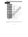
SHENZHEN SPEEDLEADER TECHNOLOGY User Manual LVP8000 LED Splicing Processor About the Manual Without the written permission of the company, it is forbidden for any company or individual to imitate, copy, or transcribe part or all of the contents of the manual. It is not allowed to have the commodity publicity or achieve any commercial or profit-seeking purpose in any form (electronic form, mechanical form, photocopying form, recording form, or other possible ways). Please carefully read this manual before using this equipment. All the product specifications and information mentioned in the manual are only for reference. If there is the content updating, the company will not make further notice. Unless there is a special agreement, this manual is only taken as an instruction, and all statements and information will not constitute a guarantee of any kind. Brand Royalty VGA and XGA are the registered trademarks of IBM Corporation. VESA is a trademark of the Video Electronics Standards Association. The logo of HDMI and High-Definition Multimedia Interface are the trademark of HDMI Licensing LLC. Safety Instructions This symbol prompts the user that there are the important operation and maintenance instructions in the user manual. SHENZHEN SPEEDLEADER TECHNOLOGY CO.,LTD. LED Video Processor This symbol warns the user that there is the hazardous voltage exposed inside the equipment and there is the electric shock hazard. This equipment must be connected with ground wire. This equipment needs a rated power voltage. Ensure that the input voltage error should be between - 10% and +10%. Do not connect AC power cord with another AC power cord which may lead to excessive noise. Please use the equipment when the surrounding temperature is from -10 ℃ to Do not use this equipment in certain special circumstances, such as, closing to 45 ℃, and the relative humidity is 90% or less than that. a heat source, which may cause overheating of the equipment and damage it. Please use it in a well-ventilated place and pay attention not to block the equipment vents. Do not expose this equipment in the place which has the possibility for accidental collision or vibration, and reinforcement processing is necessary in the vibration place. When you use the equipment, please make sure that there are no objects, such as water and metal objects, inside the equipment. Otherwise, it will damage the equipment and cause a fire. If there is any irregularity or abnormality for the equipment, please immediately turn off the power supply, disconnect the AC power cord, and see “Trouble Clearing”. If this equipment is damaged, do not disassemble it. Please contact our maintenance service department. Page 1 of 56 SHENZHEN SPEEDLEADER TECHNOLOGY CO.,LTD. LED Video Processor Contents Overview .............................................................................................................................. 4 Application ........................................................................................................................... 5 Installation ........................................................................................................................... 7 Install LED Sending Card................................................................................................ 7 Install LVP8000 .............................................................................................................. 8 Rear Panel ....................................................................................................................... 9 Operation Interface………………………………………………………………………. 13 Menu System.......................................................................................................... ………..17 Menu System Overview ................................................................................................ 17 Enter the Menu .............................................................................................................. 18 Automatic Menu ............................................................................................................ 19 Input Menu .................................................................................................................... 20 Output Menu.................................................................................................................. 22 Splice Menu................................................................................................................... 23 Function Menu .............................................................................................................. 26 Advanced Menu ........................................................................................................... 28 Preset Menu ................................................................................................................... 30 System Menu ................................................................................................................. 31 Operation ........................................................................................................................... 32 Factory Resetting ........................................................................................................... 32 Output Resolution setting .............................................................................................. 33 Select the Input .............................................................................................................. 34 Page 2 of 56 SHENZHEN SPEEDLEADER TECHNOLOGY CO.,LTD. LED Video Processor Preview and Seamless Switching .................................................................................. 36 Set Fade Time and Preview Switching Mode ................................................................ 38 Adjust Output Window Position .................................................................................... 38 Crop Size and Position of Output Window.................................................................... 39 Brightness and Contrast of Output Window .................................................................. 41 Save and Recall of the Preset......................................................................................... 43 Splicing Setting and Application ................................................................................... 45 Specifications ..................................................................................................................... 51 Trouble Clearing ................................................................................................................ 55 Page 3 of 56 SHENZHEN SPEEDLEADER TECHNOLOGY CO.,LTD. LED Video Processor Overview LVP8000 is a powerful four-channel splicing processor, which can support four independent video processors, 4×4 channel hybrid matrix and 4096×2304 high-resolution picture output. For a single processor, it can splice a maximum of 10240 × 960 or 4096 × 2304 or 1920 × 4800 picture output, which is much higher than 8M video output. It is the ideal video demonstration equipment, which can be applied to large-scale performance, command, control center, video conference, medical facility, meeting room and court. LVP-8000 can accommodate a wide range of input source, with four-channel independent picture processing engine and four-channel fully configurable input, which can switch in sixteen-channel video input, including four-channel DVI, four-channel VGA, four-channel VID and four-channel 3G-SDI (optional). Every channel can receive standard resolution or high-resolution video signal, with the maximum resolution input reception of 1920 x 1200 @ 60Hz. LVP-8000 can output four-channel video with rich interfaces. The output applies DVI-I and DVI-D interface, which can realize two-channel DVI and one-channel VGA (using DVI to VGA connector to connect the DVI-I interface) and meet more device attachment. The output resolution of each channel can be set by the user, with the maximum output of 1920 x 1200 @ 60Hz or 2048 x 1152 @ 60Hz resolution, which can meet various high-definition performances. LVP-8000 can achieve different kinds of splice modes, such as, equal splice, unequal splice, super wide and super high splice, simplifying user’s installation. Four-channel independent picture processor is internally installed in LVP-8000 with powerful video processing and switching function, which can achieve single-input to multiple-output or multiple-input to multiple-output video switch, equal to a 4 × 4 channel hybrid matrix. LVP-8000 can be configured into four independent video processors to reduce the use of a large number of video processors and improve the performance quality. Page 4 of 56 SHENZHEN SPEEDLEADER TECHNOLOGY CO.,LTD. LED Video Processor Users can define seamless switching of any channel. Users can choose two outputs and set them as Preview and program, by which seamless switching can be perfectly achieved. LVP-8000 is easier to use with powerful functions and humanist design. If users touch the keystroke and menu system, they can complete the complicated settings. The complete setting and operation can be achieved by front keystroke, RS-232 and IP Link. LVP-8000 provides rich physical interfaces to meet the requirements of output equipment and provides installation sites for more than four LED sending cards, which simplifies lots of setting and installation. The knob can quickly adjust the frame parameters, which is convenient for the users. Application Figure 1-1 shows a typical application of LVP-8000 splicing processor. LVP-8000 can receive a variety of signal and resolution input and support SD resolution to HD resolution video input as follows: z VGA (XGA, WUXGA) video z DVI (compatible HDMI 1.3) z Composite video (NTSC, PAL, SECAM) z SD/HD/3G-SDI (optional) Page 5 of 56 SHENZHEN SPEEDLEADER TECHNOLOGY CO.,LTD. LED Video Processor Figure 1-1 Application of LVP-8000 Splicing Processor LVP-8000 with various input and output interfaces, can access VGA and DVI signals of the desktop computer, VGA and HDMI signal of the laptop, SDI signal of high-definition camera, DV and DVD video signal. At the same time, LVP-8000 has four-channel output. Each channel has tow DVI interfaces, which can realize two-channel DVI and one-channel VGA signal (DVI/VGA interface is multiplexed interface, which has DVI and VGA signal output) and meet user’s needs. Four-channel output of LVP-8000 sends to the LED sending card and sending card will then connect the LED video wall. There are four installation location for LED sending card and four 5V Direct Current supply in it. According to configuration, users can take any tow-channel output as switch with preview. When necessary, users can use software or console to fully control LVP-8000. Page 6 of 56 SHENZHEN SPEEDLEADER TECHNOLOGY CO.,LTD. LED Video Processor Installation Install LED Sending card 1. Remove the chassis cover, get rid of the chassis bezel and install fixed double-screw bolt in the correspondence position in order to load the corresponding brand sending card. Figure 2-1 Install LED Sending Card and Remove the Cover 2. Install LED Sending Card and fix it with the supplied M3 screws, then plug the 5V power supply cable into electric outlet of Sending Card, as shown in the picture. After installing the Sending Card, install the chassis bezel. Page 7 of 56 SHENZHEN SPEEDLEADER TECHNOLOGY CO.,LTD. LED Video Processor 5V power supply Figure 2-2 Install LED Sending Card Install LVP-8000 The user can choose whether to install LVP-8000 to the rack or flight case. LVP-8000 has a standard 2U chassis, with the size of 8.8cm (Height) x 44cm (Width) x 33CM (Depth). While installing, please avoid scratching the case and use cushion for fixing suspension loop. Page 8 of 56 SHENZHEN SPEEDLEADER TECHNOLOGY CO.,LTD. LED Video Processor Figure 2-3 Install LVP8000 Rear Panel Figure 2-4 Connection Terminals of LVP-8000 Rear Panel ① # 1 ~ # 4 channel video input Page 9 of 56 SHENZHEN SPEEDLEADER TECHNOLOGY CO.,LTD. LED Video Processor It can receive a 4-channel video at the same time, and each channel can receive VGA signal, DVI signal, HDMI signal (DVI terminal), VID (CVBS) and SDI signal. LVP-8000 offers a number of input interfaces which can connect 16-channel video. After a one-time access, the user can quickly switch video source without reconnection, by configuring the input source through the menu. The following are the corresponding terminal for the input interfaces: DVI input - DVI-D VGA input - DB15 SDI input - BNC VID input - BNC Figure 2-5 LVP8000 Channel # 1 Input Interface ②③ Communication Interface ② TCP / IP interface, using RJ-45 terminal, is reserved for the communication interface. ③ RS-232 interface, using DB9 terminal, when it is connected by computer’s RS-232 or console, resolution adjustment, channel selection, splicing mode, and pre-installation can be operated on LVP8000. ④ video output interface Page 10 of 56 SHENZHEN SPEEDLEADER TECHNOLOGY CO.,LTD. LED Video Processor Video output includes OUTPUT # 1 ~ OUTPUT # 4 channels, and each channel has two DVI interface, which can output two-channel DVI signal and the DVI / VGA interface can output DVI and VGA by using DVI-VGA adapter. These two interface output has the same video screen and resolution, and the resolution can be changed. The output can be connected with LED Sending Card, projectors and monitors. Figure 2-7 is a classic connection, in which output is connected to LED Sending Card, and the Sending Card is connected to LED video wall. LED Wall Figure 2-7 LVP-8000 Output Connection ⑤Installation Location for LED Sending Card LED Sending Card is the video transmission device, connecting LVP-8000 and LED display wall. LVP-8000 set aside four commonly used LED Sending Card installation space, provide installation accessories, with which users can have the installation by themselves. After installation, DVI output interface can be connected to the DVI input terminal of the LED Sending Card. Page 11 of 56 SHENZHEN SPEEDLEADER TECHNOLOGY CO.,LTD. LED Video Processor AC Switch Sending Card AC Power connector Figure 2-8 Sending Card Installation Location and AC Input ⑥ ⑦ AC power connector and AC switch LVP8000 provides a standard IEC power, with the input power of 100 ~ 240VAC, 50Hz or 60Hz, at the same time, the ground wire of the power supply must be grounded to avoid equipment damage or the electric shock to human body. Page 12 of 56 SHENZHEN SPEEDLEADER TECHNOLOGY CO.,LTD. LED Video Processor Operation Interface All the control and instruction of splicing processor are set on the front panel (see Figure 3-1). These keys provide yellow and green background lights, which indicate the current input selection and functional operation. A 240×64 LCD window indicates the current state of the splicing processor, such as menu selection, data status, and other parameters. Figure 3-1 LVP-8000 Front Panel ① FREEZE: Screen Freeze Key FREEZE key can freeze the current channel frame. When FREEZE key is working, the key shows green light, and if the user presses the key again or selects other input, the frozen frame will be canceled. ② INPUT 1~4 Input Selection Key The input channel for this group of Input Selection Key is INPUT # 1~ # 4. When the input channel is selected, the key will show yellow light. For operation, you need first press 1~4 key in OUTPUT WINDOWS keypad, and then choose 1~4 key in INPUT Page 13 of 56 SHENZHEN SPEEDLEADER TECHNOLOGY CO.,LTD. LED Video Processor keypad. LVP-8000 will record every input video data, such as, output window position, size, brightness, interception mode. ③ BLACK key Black screen output key: if the key is pressed, the current channel will get black screen output, and the key flashes yellow light. When it is pressed again, black screen will disappear. ④ OUTPUT WINDOWS 1 ~ 4 Key There are four keys in OUTPUT WINDOWS area, corresponding to OUTPUT # 1 ~ # 4. For operation, generally speaking, the user should first choose 1 ~ 4 key in OUTPUT WINDOWS area, and then press other keys, such as, signal switch, position adjustment, screen size adjustment and interception adjustment. ⑤ PICTURE ADJUST Key Press the key in the PICTURE ADJUST area, and the parameters of the current output window will be changed. When the user chooses OUTPUT WINDOWS 1~4 key, and presses picture attributes key in PICTURE ADJUST area, parameters of the currently selected output window can be adjusted. Figure 3-2 Picture Adjustment keypad (PICTURE ADJUST) Page 14 of 56 SHENZHEN SPEEDLEADER TECHNOLOGY CO.,LTD. LED Video Processor WIN SIZE-output window size: when selecting the output window, the user should press the WIN SIZE key to enter the settings, and using the knob, the user can adjust the size of the output window. WIN POS-output window position: when selecting the output window, the user should press the WIN POS key to enter the settings, and using the knob, the user can adjust the position of the output window. BRI/CONT- brightness and contrast, when selecting the output window, the user should press the BRI/CONT key to enter the settings, and using the knob, the user can adjust the brightness and contrast of the output window. TAKE-switching key: when operating, the user can press the key to enter the seamless switching menu. The user should first press OUTPUT WINDOWS1~4 key for preview, and at the same time use knob to adjust the output # 1 ~ # 4 and then press TAKE key for switching. The user can enter the menu to set the switching effects. CROP SIZE-output window crop size: when selecting the output window, the user should press the CROP SIZE key to enter the settings, and the knob can adjust the horizontal and vertical total pixel of the output window. CROP POS-output window crop position: when selecting the output window, the user should press the CROP POS key to enter the settings, and the knob can adjust the Intercept position of the output window. ⑥ State Display LVP-8000 has a 240 x 64 LCD window indicating the current state of the splicing processor, menu selection, data state and other system parameters, which will be described in detail next. ⑦ Menu Operation Page 15 of 56 SHENZHEN SPEEDLEADER TECHNOLOGY CO.,LTD. LED Video Processor MENU-menu key: press the Menu key to enter the main menu system or return to the previous menu, whose function will be introduced in detail in the following chapter. ENTER-confirming key: which means to enter a menu or confirm the operation. ⑧ : horizontal adjustment knob; : vertical adjustment knob: which can adjust menu options and parameters, or adjust the size and position of the output window. ⑨ USB interface The USB communications interface for LVP8000 or provide 5VDC/500mA power supply. Page 16 of 56 SHENZHEN SPEEDLEADER TECHNOLOGY CO.,LTD. LED Video Processor Menu System Menu System Overview LVP8000 has a convenient menu system; Figure 4-1 shows the default display menu after electrifying LVP8000. The user can observe the current corresponding input information source and other important information by default menu cycle. Electrify Output #1 Input Output Speed Leader <#1:DVI <1920x1080/60> Splicing <Equal> Default Menu Output #4 Input MENU System Main Menu …… MENU NOSYNC Output Splicing Page 17 of 56 <#1:DVI NOSYNC <1920x1080/60> <Equal> SHENZHEN SPEEDLEADER TECHNOLOGY CO.,LTD. LED Video Processor Figure 4-1 System Menu Flowchart There are four keys to operate the menu and change the parameters: MENU: press this key to activate the main menu, and after entering the main menu, press the MENU key to return to upper step of the menu. ENTER: it is confirmation key. By pressing the ENTER key, the user can enter to the sub-menu or change the operation. Knob: horizontal knob, you can adjust the horizontal menu options by this key. When choosing the picture adjustment key, the user can adjust parameters or the size and position of the output window. Knob: vertical knob, you can adjust the vertical menu options by this key. When choosing the picture adjustment key, the user can adjust the size and position of the output window. Attention:When the user presses the MENU key, ENTER key can work. Attention: When the user enters to the sub-menu, the menu system will automatically return to the default menu cycle if there is no operation for 30 seconds. Enter the Menu Press the MENU key in the default menu, LVP-8000 will enter to the main menu system. Figure 4-2 is the first level menu displayed on the LCD by main menu system. The first level sub-menu includes AUTO, INPUT, OUTPUT, SPLIC,FUNC, ADV, MAIN MENU and SYSTEM. The user can enter quickly to the submenu by ENTER key and knob. Page 18 of 56 SHENZHEN SPEEDLEADER TECHNOLOGY CO.,LTD. LED Video Processor AUTO INPUT OUTPUT SPLICE FUNC ADV PRESET SYSTEM Figure 4-2 The First Layer Submenu AUTO The function of LVP-8000 AUTO Menu is to classify and replace the user’s data and resume one or more user’s parameters to the factory default state. Figure 4-3 expands the sub-menu and parameters which can be set in AUTO Menu. The AUTO restores all the user data related to the window size, window position, and CROP size and position of the output window. AUTO Output Knob Type AUTO Knob adjustment ENTER adjustment crop、window #1,#2,,#3,#4,#1& #2,#3,#1 crop&window Page 19 of 56 SHENZHEN SPEEDLEADER TECHNOLOGY CO.,LTD. LED Video Processor Figure 4-3 Automatic Menu Flowchart Output: output channel select, and all, each channel contains type attribute. Type: It contains two sets reset data of crop and window. crop includes crop position, crop size; window includes the position and size of the window. Auto: When selecting the reset parameters, the user can choose Auto and press ENTER to confirm the reset for the currently selected output window or crop mode. Example: When selecting output # 1, type crop & window , and press the ENTER key in Auto submenu, LVP8000 will automatically reset the crop and window size, position, the input information source and other related data of output # 1 to the default state. INPUT LVP8000 input menu mainly sets information source, brightness, contrast, color and other parameters for each channel. Figure 4-4 shows the submenu and revisable data in the input menu, all the parameter settings can be completed by the knob and the ENTER key. Page 20 of 56 SHENZHEN SPEEDLEADER TECHNOLOGY CO.,LTD. LED Video Processor INPUT #1、#2、#3、#4 Input Source knob adjustment:DVI、VGA、VID、SDI Brightness knob adjustment:0~64~127 Contrast knob adjustment:0~64~127 Color knob adjustment:0~64~127 Amplitude knob adjustment:red, green, blue:0~255 Cut off knob adjustment:red, green, blue:‐31~0~31 Gamma knob adjustment:-2.5~off~2.8 ENTER key for reset Reset Figure 4-4 Input Menu Flowcharts Input - LVP-8000 has four-channel input, and each channel owns“1、2、3、4” in the INPUT key area on the corresponding panel key. Every channel has four-video input: DVI, VGA, VID, SDI. Page 21 of 56 SHENZHEN SPEEDLEADER TECHNOLOGY CO.,LTD. LED Video Processor Source-Information source matches along with input channel. After selecting input channel (for example, # 3-channel is selected), the user should change input source and connect the channel with information source. Every source has its own brightness, contrast, color saturation, RGB amplitude, RGB cut off and Gamma. Brightness / Contrast: the brightness and contrast of each source can be adjusted by input menu or BRI / CONT shortcut key in the key panel. Attention: while adjusting the brightness, it is recommended to adjust the contrast at the same time to achieve a better video quality. Color: adjust the color saturation level of the image. When the overall color is too weak or too strong, adjust the value to change the color saturation. OUTPUT Output menu is to change the output resolution. The user can browse in the menu and select the appropriate resolution as the output. The following is LVP-8000 output resolution list. 800×600@60Hz 1680×1050@60Hz 1024×768@60Hz 1920×1080@60Hz 1280×1024@60Hz 1920×1200@60Hz 1366×768@60Hz 2048×1152@60Hz 1440×900@60Hz 2560×960@60Hz 1600×1200@60Hz 1920×1080@50Hz 1280×720@50Hz Page 22 of 56 SHENZHEN SPEEDLEADER TECHNOLOGY CO.,LTD. While changing the output resolution, LED Video Processor vertical knob can help the user select a different resolution, press ENTER for confirmation, and finally there will be prompts on the LCD display screen for user whether to confirm the changes or not. When the user wants to accurately set resolution, the user needs to press WIN SIZE key to enter the shortcut menu. About the setting of output resolution, it will be introduced later. Tip: after modifying the output resolution, window size, window position, crop size, crop position in LVP8000 will reset to the default state. If the output resolution previously saved by the user in the pre-setting stage is different from the current output resolution, this presetting will be not sued. SPLICE Splice menu is set for equal splicing and unequal splicing through multi-output interfaces. Every interface displays part of the screen and splices a complete picture. The following is structure flowchart of splicing menu. Page 23 of 56 SHENZHEN SPEEDLEADER TECHNOLOGY CO.,LTD. SPLICE LED Video Processor Output #1~#4 Output #1 Corresponding 1~4 key in OUTPUT Splice knob adjustment,equal splicing , unequal splicing, splicing closing H splice unit : 1 V splice unit: 1 Splice pos: 1 H Total size 1920 V Total size 1080 H Splice pos 0 V splice pos 0 Figure 4-5 Splicing Menu Flowchart Page 24 of 56 SHENZHEN SPEEDLEADER TECHNOLOGY CO.,LTD. LED Video Processor Output - according to the needs, user can choose output channels # 1 ~ # 4, and the corresponding keys are key 1~4 in OUTPUT WINDOWS key area. If you want to change the channel, you can press key 1~4 in OUTPUT WINDOWS key area. After selecting output channel, the user should set the splicing parameter. Splice- splicemode can divide into equal splice, unequal splice and splice closing. When the resolution in two or more splicing regions is the same, the user can apply equal splicing. When the resolution is different, the unequal splicing can be applied. When it is not necessary to use splicing, then the user can close the splice. According to the splice menu, the user can select equal or unequal splice, and then parameter setting menu will show two output forms, one is equal splicing parameter and the other is unequal splicing parameter. Equal Splice Splice position: display several parts of the screen and the computation sequence of the position are from left to right; and from top to bottom, as shown in Figure 4-6. Figure 4-6 Splicing Position Sequence H splice unit: the number of horizontal splicing, see 3 in 1x3 splicing mode of Figure 4-6. V splice unit: the number of vertical splicing, see 1 in 1x3 splicing mode of Figure 4-6. Page 25 of 56 SHENZHEN SPEEDLEADER TECHNOLOGY CO.,LTD. LED Video Processor Unequal splice. H Total size: total horizontal pixels of video wall. V Total size: total vertical pixels of video wall. H splice pos: horizontal starting pixels displayed by current output. V splice pos: vertical starting pixels displayed by current output. The splicing operation will be described in detail in the following sections. FUNC When the user uses preview switching function, the function menu will mainly adjust the switching effect between preview and program. Figure 4-7 shows the contents of the function menu, including preview switching mode and fade time. Func Preview switch Fade time Knob adjustment Knob adjustment swap stay 0~5S Figure 4-7 Function Menu Flowchart Page 26 of 56 SHENZHEN SPEEDLEADER TECHNOLOGY CO.,LTD. LED Video Processor Preview switch: LVP-8000 can take any two channel outputs as a preview and program output, between which the switching is seamless exchange. The switching mode is swap and stay. The user can operate it by press TAKE key in PICTURE ADJUST key area. When the preview switching mode is swap, if the user switches the preview screen to the program, the program on the screen will be showed on the preview display screen, that is, the picture on preview display screen switches with the program picture, as shown in Figure 4-8. When the preview switching mode is stay, if the user switches the preview screen to the program, the picture on the preview display screen will not change, and the picture on preview display screen is the same with the program picture, as shown in Figure 4-9. A TAKE Preview Display Screen Display Wall Figure 4-8 Preview Switching Mode: Exchanging Page 27 of 56 SHENZHEN SPEEDLEADER TECHNOLOGY CO.,LTD. LED Video Processor TAKE Preview Display Screen Display Wall Figure 4-9 Preview Switching Mode: Following Fade time: it refers to the time length of resolute effect for switching preview picture into program. The user can press TAKE key, and LVP-8000 will decide the transition time length of picture switching by fade time. ADV The setting items in advanced menu are synchronous mode and VGA setting. Synchronous mode can make simultaneous display of the splicing pictures, when multiple devices splice at the same time. While adjusting the VGA input, VGA setting is to regulate VGA picture deviation or picture unclarity manually or automatically. Page 28 of 56 SHENZHEN SPEEDLEADER TECHNOLOGY CO.,LTD. ADV Knob adjustment LED Video Processor Free run, v lock, EXT Sync GENLOCK TYPE VGA Setup Press ENTER key for accessing Knob adjustment,#1~4 Input Auto Adjust ENTER key for regulation H Position Knob adjustment V Position Knob adjustment Knob adjustment H clock Clock Phase Knob adjustment Figure 4-10 System Menu Flowchart GENLOCK TYPE has three types, free run, V Lock and EXT Sync. Free run is for single LVP8000 setting. When using multi- LVP8000 for splicing, the synchronization mode should be V Lock. When input source is external synchronization signal (usually field synchronization signal), it can be connected with external synchronization input, then the synchronization mode should be EXT Sync. Page 29 of 56 SHENZHEN SPEEDLEADER TECHNOLOGY CO.,LTD. LED Video Processor VGA setup is that each input VGA has automatic regulation and manual regulation on the position, clock and phase parameters. This menu can be used to adjust VGA picture deviation. PRESET Preset menu is used to save and recall scene mode. According to souce and recall, the user can quickly rebuild scene parameters, and eliminate repetitive and complex settings. Saving LVP8000 presetting is to save the preset data for all channels. When oeculling the presetting, the user can transfer it to the output selectively. Preset Menu Recall Save Erase choose ★1~10 choose output choose ☆1~10 ENTER key for saving choose ★1~10 ENTER key for erasing ENTER key for recall Figure 4-11 Preset Menu Flowchart Recall: the user can recall the saved preset in this menu. ★ means there is the preset. ☆ indicates that there is no preset. Before transferring, the user should use choose the saved preset ★1~10, and then use knob to knob to choose target channel output # Page 30 of 56 SHENZHEN SPEEDLEADER TECHNOLOGY CO.,LTD. LED Video Processor 1 ~ # 4. The user can still press 1, 2, 3, 4 key in the key area of ENTER key + INPUT key for a quick call. Save: the user can save the current output window, the source, the picture color and other parameters as the preset. ★ means there is the preset. ☆ indicates that there is no preset. Before saving, the user should select the target channel, the program or preset, and then choose one from group 1 to group 10, finally press ENTER to save it. When saving, ☆ will change into ★to prompt the user that you have saved it. Erase: the user can use knob to choose the number in ★1~10, and press ENTER to erase the preset data. SYSTEM System menu can set the menu system language, check system version information and reset the entire system menu. Figure 4-12 shows the submenu and parameters in the system menu. SYSTEM Knob Adjustment,Chinese, English Language Hardware x.x.x System Version Factory reset ENTER key for access Figure 4-12 System Menu Flowchart Page 31 of 56 SHENZHEN SPEEDLEADER TECHNOLOGY CO.,LTD. LED Video Processor Language: the user can set the Chinese or English for the entire menu system including default circulating menu, System Version: the user can check the software and hardware version of the device. Factory reset – all the parameters can be resumed to the factory default. Operation For commonly used functions, such as LVP-8000 factory resetting, output resolution setting, input source selection, switching, output window operation, brightness and contrast adjustment and saving and recalling of the preset scene, will be introduced in detail in the following parts. Factory Resetting The user may need to reset operation for the factory default. System Default menu Main Menu Factory SYSTEM Confirmation Reset MENU +ENTER +ENTER Figure 5-1 Factory Resetting Operation Flowchart Page 32 of 56 ENTER SHENZHEN SPEEDLEADER TECHNOLOGY CO.,LTD. LED Video Processor Steps: in the default menu, first enter the factory resetting menu in the system menu (shown in Figure 5-1), and then press ENTER to reset. Output Resolution Setting There are two steps for setting the resolution: firstly the user should choose an appropriate resolution and then precisely adjust each output resolution. 1. Choose an Appropriate Resolution LVP-8000 output # 1 ~ # 4 shares the same output resolution, which can be set in the system menu as follows: …… 1920×1080@60Hz System Default menu output Main Menu 1920×1200@60Hz …… MENU +ENTER +ENTER Confirmation ENTER Figure 5-2 - Modifying Output Resolution Flowchart Steps: in the default menu, the user should first enter the output menu (shown in Figure 5-2) and then select the appropriate resolution, finally press ENTER to confirm. 2. Precisely Adjust Output Resolution Page 33 of 56 SHENZHEN SPEEDLEADER TECHNOLOGY CO.,LTD. LED Video Processor Because the output resolution on the each interface is different, LVP-8000 # 1 to # 4 output resolution can modify by itself, which can be realized by operating the relevant key. ① ② ③ window horizontal width: 960 Output #1 vertical height: 632 Figure 5-3 Precisely Adjust Output Resolution Steps: ① Select 1 to 4 key in OUTPUT WINDOWS key area, at this time, the key which is pressed will show yellow light. ② Press WIN SIZE key in the PICTURE ADJUST key area, at this time, the LCD screen shows the menu to adjust window size. ③ In the window adjustment menu, use width of the window, and use , the horizontal knob to adjust horizontal pixel the vertical knob, to adjust vertical pixel height of the window. Select the Input Page 34 of 56 SHENZHEN SPEEDLEADER TECHNOLOGY CO.,LTD. LED Video Processor LVP-8000 has 4-channel input and the number 1 to 4 in the INPUTS key area matches with INPUTS # 1 to # 4 interfaces. Each channel can also be configured to DVI, VGA, VID and SDI. The information source is for the output window, and the user should first select output (in OUTPUT WINDOWS key area), and then select the input source. Before using the INPUT key areas, the user should set input source of each channel. 1. Setting Input Each channel of LVP-8000 has four physical interfaces (DVI, VGA, VID, SDI), which can be accessed partly or completely. The user can choose one of the interfaces by menu configuration. Default menu System Main Input Menu Input #1 MENU +ENTER Source VID Figure 5-4 Configure Input Information source Operation Flowchart Steps: See Figure 5-4, in the input of the main menu, the horizontal knob will be firstly selected for the input channel # 1 ~ # 4; and then use the knob in the information source to select DVI, VGA, VID and SDI. 2. Selecting Input LVP8000 has four output channels, and each channel can select any one from 1 to 4 in INPUTS key area, which is similar to matrix, and each information source can output to one or more interfaces, which is very flexible to use. Page 35 of 56 SHENZHEN SPEEDLEADER TECHNOLOGY CO.,LTD. LED Video Processor ① ② Figure 5-5 Selecting Information source Operating Flowchart Steps: ① Select 1 to 4 key in OUTPUT WINDOWS key area, at this time, the key which is pressed will show yellow light. ② Press 1 to 4 key in INPUT key area, and the device will have immediate output. At this time, the key which is pressed will show yellow light. Preview and Seamless Switching LVP8000 has a user-defined preview function. The defined preview and program can be switched seamlessly. For operation, the user should first enter preview switch state, set the corresponding relation between preview and program and then press the TAKE key. Page 36 of 56 SHENZHEN SPEEDLEADER TECHNOLOGY CO.,LTD. LED Video Processor ② ①③ ② preview:output #4 program:output #1 fade time: 1.5S Figure 5-6 Preview and Seamless Switching Operation Flowchart Steps: ① In the default menu, press TAKE key in PICTURE ADJUST key area, and enter switching menu state. ② In LCD switching menu, press 1 to 4 key in OUTPUT WINDOWS key area to change the preview channel, use knob to change program channel, and use knob to adjust the fade time. ③ Set the preview channel, program channel and fade time and then press the TAKE key, you can achieve seamless switching. Page 37 of 56 SHENZHEN SPEEDLEADER TECHNOLOGY CO.,LTD. LED Video Processor Set Fade Time and Preview Switching Mode There are tow ways for controlling switching mode: fade time and preview switching mode. Preview switching mode has two kinds: swap and stay. Fade time can be set from 0 to 5 seconds, as shown in the following chart. Preview Switch :stay System swap FUNC Main Menu Default menu MENU +ENTER Fade Time 1.5S Figure 5-7 Set Fade Time and Preview Switching Mode Flowchart Steps: as shown in Figure 5-7, enter the function menu of the menu system in the default menu, use time, use knob to change the Preview Switching Mode, sway or stay. During fade knob to adjust the fade time from 0 to 5 seconds. Adjust Output Window Position If needed, the user may adjust output window position, which can solve the problem of picture deviation (see the following method). Page 38 of 56 SHENZHEN SPEEDLEADER TECHNOLOGY CO.,LTD. LED Video Processor ① ② ③ Output #1 window :horizontal starting point 0 vertical starting point:: 0 Figure 5-8 Adjust Output Window Position Operation Flowchart Steps: ① Select 1 to 4 key in OUTPUT WINDOWS key area, at this time, the key which is pressed will show yellow light. ② Press WIN POS key in the PICTURE ADJUST key area, at this time, the LCD screen shows the menu to adjust window size. ③ In the window adjustment menu, use window, and use knob to adjust horizontal position of the knob, to adjust vertical position of the window. Crop Size and Position Crop of the output window means to crop part of the picture after being enlarged. The user can adjust the crop proportion and crop position. See the following method: Page 39 of 56 SHENZHEN SPEEDLEADER TECHNOLOGY CO.,LTD. LED Video Processor 1. Adjust the crop Size of Input Window ① ② ③ Output H size: V size: #1 Crop 1024<100%> 768<100%> Figure 5-9 Adjust Output Window Position Operation Flowchart Steps: ① Select 1 to 4 key in OUTPUT WINDOWS key area, at this time, the key which is pressed will show yellow light. ② Press CROP SIZE key in the PICTURE ADJUST key area, at this time, the LCD screen shows the menu of crop window size. ③ In the crop adjustment menu, use use knob to adjust horizontal size of the window, and knob, to adjust vertical size of the window. The LCD screen will show the percentage of magnification. 2. Adjust the crop position of the output window Page 40 of 56 SHENZHEN SPEEDLEADER TECHNOLOGY CO.,LTD. LED Video Processor ① ② ③ Output #1 interception :horizontal starting point 0 vertical starting point: 0 Figure 5-10 Adjust Output Window Position Operation Flowchart Steps: ① Select 1 to 4 key in OUTPUT WINDOWS key area, at this time, the key which is pressed will show yellow light. ② Press CROP POS key in the PICTURE ADJUST key area, at this time, the LCD screen shows the menu of crop position. ③ In the crop adjustment menu, use window, and use knob to adjust horizontal starting pixel of the knob, to adjust vertical starting pixel of the window. Brightness and Contrast of Output Window Page 41 of 56 SHENZHEN SPEEDLEADER TECHNOLOGY CO.,LTD. LED Video Processor According to the actual conditions, the user may need to adjust the brightness and contrast. The brightness and contrast of four-channel of LVP8000 can be adjusted independently. The adjustment method is as follows. ① ② ③ Output #1 Brightness: BRI/CONT 64 Contrast: 64 Figure 5-11 Adjust Brightness and Contrast Operation Flowchart Steps: ① Select 1 to 4 key in OUTPUT WINDOWS key area, at this time, the key which is pressed will show yellow light. ② Press BRI/CONT key in the PICTURE ADJUST key area, at this time, the LCD screen shows the menu of Brightness and Contrast. ③ In the adjustment menu, use scope of 0~127), and use knob to adjust the brightness of the window (with the knob, to adjust the contrast of the window (with the scope of 0~127). Page 42 of 56 SHENZHEN SPEEDLEADER TECHNOLOGY CO.,LTD. LED Video Processor Save and Recall of the Preset 1. Save of the Preset The user should enter the system menu for saving the preset. The saved preset data are the current input source, output picture size and position and splicing state. The operation is shown in Figure 5-12, to enter the preset save menu. System Default Menu Preset Main Menu Save ENTER MENU +ENTER ☆1~10 Choose ☆1~10 ENTER key for saving Figure 5-12 Preset Saving Operation Flowchart Steps: As shown in Figure 5-12, the user can enter the preset menu in the default menu; use this knob to choose from1 to 10, and save it by pressing ENTER key. After saving, the ☆ which the preset number corresponds will change into ★. 2. Recall of the Preset There are two ways for recalling the preset, one is menu recall, and the other is shortcut key combination. The difference of the two ways is that menu recall can recall all the preset, but the shortcut key combination can only recall one to four group preset. Page 43 of 56 SHENZHEN SPEEDLEADER TECHNOLOGY CO.,LTD. LED Video Processor Menu Recall of the Preset System Default Menu Preset Main Menu Recall MENU +ENTER ENTER ENTER Output #1~#4 ★1~9 Choose: output channel Choose ★1~10 ENTER transfer Figure 5-13 Transfer of the Preset Operation Flowchart Steps: As shown in Figure 5-12, the user can enter the preset menu in the default menu; use this knob to choose the output channel and use recall can work. Shortcut Key Combination Transfer: Page 44 of 56 to choose 1 to 10, and then the SHENZHEN SPEEDLEADER TECHNOLOGY CO.,LTD. LED Video Processor Figure 5-14 Shortcut Key Combination Transfer Operation Flowchart Steps: Press the ENTER key and 1 to 4 key in the INPUTS key area, at the same time, the user can recall four-group preset. Tip: If the current output resolution is different from the default resolution. LCD display will prompt the user that “you cannot transfer the preset because of the different resolution”. Setting and Application of the Splicing The splicing function of LVP-8000 is simple and practical, which can be operated in the splicing menu of the system. Splicing has two types, one is equal splicing and the other is unequal splicing. Equal splicing means that all the horizontal pixels and vertical pixels of the video wall are equal; the unequal splicing means that every pixel of the video wall is unequal. The following is the example of equal splicing and unequal splicing of the LED video wall. 1. LED Video Wall 2x2 Equal Splicing Example Table 5-1 Existing Devices and Related Parameters Page 45 of 56 SHENZHEN SPEEDLEADER TECHNOLOGY CO.,LTD. Device name/Type LED Video Processor Function /Parameter Number There are 4 1270x896 LED video LED Video Wall walls, by the way of 2x2 to splice an 4 LED video wall with the total pixel of 2540x1792 LED Sending Card LVP-8000 Maximum support 1280x1024 4 Video Splicing processor 1 OUTPUT#1 Sending card OUTPUT#2 OUTPUT#3 OUTPUT#4 1 2 3 4 Sending card Sending card Sending card LVP8000 2x2LED Splicing Wall Figure 5-15 LVP-8000 Equal Splicing Connection Diagram Steps: (1) Connection Connect LVP-8000, 4 LED sending cards and 4 parts LED video wall. 4 DVI outputs of LVP-8000 are separately connected to the LED sending card, and LED sending card is Page 46 of 56 SHENZHEN SPEEDLEADER TECHNOLOGY CO.,LTD. LED Video Processor connected to each part of the splicing wall by CAT5. Four parts of the LED video wall should be connected into a separate single screen. (2) Setting Send Card Set four sending cards and send relevant parameters, which will make four- part video wall work independently. For the detailed instructions on sending card, please refer to the user manual of sending card provided by the card manufacturer. (3) Set Output Resolution Select LVP-8000 output resolution of 1280x1024, and adjust OUT # 1 to # 4 resolutions as 1270x896. (4) Select input Choose every channel of LVP8000 and select the same input source for the four outputs. (5) Set the LVP-8000 Splicing Menu Output #1 Output #2 Splice:Equal Splice:Equal H Splice Unit::2 H Splice Unit:2 V Splice Unit:2 V Splice Unit:2 Splice Pos: 1 Splice Pos: Page 47 of 56 2 SHENZHEN SPEEDLEADER TECHNOLOGY CO.,LTD. LED Video Processor Output #3 Output #4 Splice:Equal Splice:Equal H Splice Unit:2 H Splice Unit:2 V Splice Unit:2 V Splice Unit:2 Splice Pos: Splice Pos: 3 4 Note: the splicing position in the splicing setting should make appropriate change according to different output connections. 2. LED Video Wall Unequal Splicing Example Table 5-2 Existing Devices and Related Parameters Device name/Type Function /Parameter Number Screen 1:1152x1024 Screen 2:960x1024 2 LED Video Wall Horizontal total pixel 2112 Vertical total pixel:1024 LED Sending Card Maximum support 1280x1024 2 LVP-8000 Video Splicing processor 1 Page 48 of 56 SHENZHEN SPEEDLEADER TECHNOLOGY CO.,LTD. OUTPUT#1 OUTPUT#2 Sending card 1 LED Video Processor 2 Sending card LED Video Wall OUTPUT#3 OUTPUT#4 LVP-8000 Figure 5-15 LVP-8000 Unequal Splicing Connection Diagram Steps: (1) Connection Connect LVP-8000, two LED sending cards and two parts LED video wall. OUTPUT#1and OUTPUT#2 of LVP-8000 are separately connected to the LED sending card, and LED sending card is connected to each part of the splicing wall by CAT5. Each part of the LED video wall should be connected into a separate single screen. (2) Setting Sending Card Page 49 of 56 SHENZHEN SPEEDLEADER TECHNOLOGY CO.,LTD. LED Video Processor Set two sending cards and send relevant parameters, which will make splicing wall work independently. For the detailed instructions on sending card, please refer to the user manual of sending card provided by the card manufacturer. (3) Set Output Resolution Select LVP-8000 output resolution of 1280x1024, and adjust resolution of OUT # 1 as 1152x1024 and resolution of OUT#2 as 960x1024. (4) Select input Choose every channel of LVP8000 and select the same input source for OUTPUT#1and OU’TPUT#2. (5) Set the LVP-8000 Splicing Menu Output #1 Output #2 Splice:Unequal Splice:Unequal H Total Size:2112 H Total Size:2112 V Total Size:1024 V Total Size:1024 H splice Pos:0 H Splice Pos:1152 V Splice Po:0 V Splice Pos:0 Note: the splicing position in the splicing setting should make appropriate change according to different output splicing connections. Page 50 of 56 SHENZHEN SPEEDLEADER TECHNOLOGY CO.,LTD. LED Video Processor Specifications DVI video input Number Connector 4 DVI-I DVI1.0,HDMI1.3 downward compatibility Standard Resolution VESA standard,PC to 1920x1200,HD to 1080p VGA video input Number 4 Connector DB15 R、 G、 B、 Hsync、 Vsync:0 to1Vpp±3dB (0.7V Video+0.3v Standard Sync ) 75 ohm Resolution black level:300mV Sync-tip:0V VESA standard,PC to 1920x1200 Composite video VID input(CVBS) Number 4 Connector BNC Standard PAL/NTSC/SECAM 1V±3db Page 51 of 56 (0.7V Video+0.3v Sync ) 75 ohm SHENZHEN SPEEDLEADER TECHNOLOGY CO.,LTD. Resolution LED Video Processor 480i,576i 3G-SDI video input Optional Number 4 Connector BNC Standard SD-SDI,HD-SDI,3G-SDI 1080p 60/50/30/25/24/25(PsF)/24(PsF) 720p 60/50/25/24 Resolution 1080i 1035i 625/525 line DVI video output Number 8 Connector DVI-I Standard DVI standard :DVI1.0 Resolution 800×600@60Hz 1680×1050@60Hz 1024×768@60Hz 1920×1080@60Hz 1280×1024@60Hz 1920×1200@60Hz 1366×768@60Hz 2048×1152@60Hz 1440×900@60Hz 2560×960@60Hz Page 52 of 56 SHENZHEN SPEEDLEADER TECHNOLOGY CO.,LTD. 1600×1200@60Hz LED Video Processor 1920×1080@50Hz 1280×720@50Hz VGA video output Number 4 Connector DVI-I outlet VGA standard:R、G、B、Hsync、Vsync:0 to1Vpp±3dB (0.7V Standard Video+0.3v Sync ) 75 ohm black level:300mV Sync-tip:0V 800×600@60Hz 1680×1050@60Hz 1024×768@60Hz 1920×1080@60Hz 1280×1024@60Hz 1920×1200@60Hz Resolution 1366×768@60Hz 2048×1152@60Hz 1440×900@60Hz 2560×960@60Hz 1600×1200@60Hz 1920×1080@50Hz 1280×720@50Hz General Weight 4.0kg Dimensions 8.8cm(height )x44cm(width)x33cm(depth) Page 53 of 56 SHENZHEN SPEEDLEADER TECHNOLOGY CO.,LTD. Power Supply Power consumption Working temperature Storage humidity 100VAC – 240VAC 50/60Hz 100W -10°C~45°C 10%~90% Specifications subject to change without prior notice. Page 54 of 56 LED Video Processor SHENZHEN SPEEDLEADER TECHNOLOGY CO.,LTD. LED Video Processor Trouble Clearing In the process of installing or using, problems may be encountered. The user can try to clear the trouble by the following steps. If you still cannot solve the problem, you can contact the local dealer. z The device has no image, and the indicator does not light. Check if the electric power has the poor contact. Check whether the power switch is closed. z There is LCD screen display on key panel, but without picture output. Check whether you connect the signal correctly. Check whether the device supports the resolution and refreshing frequency. Make factory resetting. z VGA screen is not for all over the screen or has deviation. Check whether the VGA wire is qualified or too long. Access to menu system: system → VGA settings→ automatic adjustment and carry out VGA automatic adjustment. Manually adjust the picture position in the VGA settings. z HDMI / DVI output picture is not for the entire screen. Reset the device output resolution. Check whether the output resolution of the PC or laptop is the same with the received resolution by splicing processor. Check whether the wallpaper is too small. Page 55 of 56 SHENZHEN SPEEDLEADER TECHNOLOGY CO.,LTD. LED Video Processor Industry Sales and Service Hotline: 400-6286-959 深圳市杰思创科技有限公司 SHENZHEN SPEEDLEADER TECHNOLOGY CO.,LTD. Tel: 0755-26588939 Fax: 0755-26586619 Post Code: 518052 Address: 6/F, Bldg. 78, Majialong Industrial Zone, Nanshan District, Shenzhen http://www.speedleader.cn Page 56 of 56