1
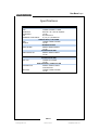
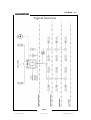
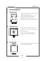
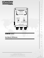
SOLO
GUARDIAN
SOLO
PRE-ALARM
TIME DELAY
15
20
0
MINUTES
CALL FOR ASSISTANCE
C-VIGIL LTD : MARINE
S A F E T Y
10
0
RESET
S Y S T E M S
GUARDIAN
User Manual – ECR Version
C-VIGIL Ltd : marine, Digital House, Foxwood Road, Chesterfield, Derbyshire S41 9RF, UK.
Switchboard: +44 (0)8432 898 464
Dir Tel: +44 (0)1246 269 469 -:- Dir Fax: +44 (0)1246 351 288
E: [email protected] -:- W: www.bridge-watch.co.uk
Company Registration No: 04407624 -:- VAT No: 804 6004 68 -:- ISO 9001 No: GB2001654
M A R I N E
GUARDIAN : S O L O
GUARDIAN
SOLO
GUARDIAN : S O L O
User Manual – ECR Version
User Manual - Page 2
GUARDIAN
Contents
TABLE OF FIGURES ............................................................................................................................................. 4
SPECIFICATIONS ................................................................................................................................................. 5
TYPICAL OVERVIEW............................................................................................................................................ 6
1.
GENERAL DESCRIPTION ............................................................................................................................ 8
1.1
Introduction............................................................................................................................................. 8
2.
SYSTEM COMPONENTS .......................................................................................................................... 10
2.1
Main Control Unit .................................................................................................................................. 10
2.2
Manual Reset Panel ............................................................................................................................... 10
2.3
Directional PIRs...................................................................................................................................... 10
2.4
360 PIR (Optional) ................................................................................................................................ 11
2.5
Main Alarm ............................................................................................................................................ 11
2.6
Wireless Reset / Panic Button (Optional) ............................................................................................... 11
3.
SYSTEM FUNCTIONS............................................................................................................................... 14
3.1
Dormant Time Period............................................................................................................................. 14
3.2
Staged Alarms........................................................................................................................................ 14
3.3
3.4
O
3.2.1
Pre Alarm ..................................................................................................................................... 14
3.2.2
Main Alarm .................................................................................................................................. 14
3.2.3
Remote Alarm System .................................................................................................................. 14
Reset Methods....................................................................................................................................... 15
3.3.1
Automatic .................................................................................................................................... 15
3.3.2
Manual......................................................................................................................................... 15
Warning Devices .................................................................................................................................... 15
3.4.1
Pre-Alarm..................................................................................................................................... 15
3.4.2
Main Alarm .................................................................................................................................. 15
3.4.3
Remote Alarm System .................................................................................................................. 15
3.5
Call for Assistance .................................................................................................................................. 15
3.6
Function Testing .................................................................................................................................... 15
SOLO
www.bridge-watch.co.uk
C-VIGIL Ltd : marine
[email protected]
User Manual - Page 3
GUARDIAN
4.
OPERATION............................................................................................................................................ 17
4.1
Power On............................................................................................................................................... 17
4.2
Dormant Time Period Selection.............................................................................................................. 17
4.3
Reset ..................................................................................................................................................... 18
4.4
Call for Assistance .................................................................................................................................. 19
4.5
Alarm Acknowledgement....................................................................................................................... 19
4.6
Stand-by ................................................................................................................................................ 20
4.7
Power Off .............................................................................................................................................. 20
5.
PERIODIC TESTING ................................................................................................................................. 22
SOLO
www.bridge-watch.co.uk
C-VIGIL Ltd : marine
[email protected]
User Manual - Page 4
GUARDIAN
Table of Figures
Figure 1 MCU Dormant Time Period Selector..................................................................................................... 14
Figure 2 Timing Diagram ................................................................................................................................... 15
Figure 3 MCU Illuminated On/Off Switch ........................................................................................................... 17
Figure 4 MCU Dormant Time Period Selector..................................................................................................... 18
Figure 5 Manual Reset ...................................................................................................................................... 18
Figure 6 Call for Assistance................................................................................................................................ 19
Figure 7 Alarm Reset / Acknowledge ................................................................................................................. 19
Figure 8 MCU Stand-by Selector........................................................................................................................ 20
Figure 9 MCU On/Off Illuminated Switch ........................................................................................................... 20
Figure 10 MCU Start Function Test .................................................................................................................... 22
SOLO
www.bridge-watch.co.uk
C-VIGIL Ltd : marine
[email protected]
User Manual - Page 5
GUARDIAN
Specifications
STANDARD SUPPLY
CONTROL PANEL
SIZE
241MM X 161MM X 73MM
POWER I/P
SHIPS AC : 86 - 265V AC 50/60HZ
POWER O/P
12V DC
I/O
N/O CONTACTS
DORMANT TIME PERIOD
0 / 10 / 15 / 20 MINUTES
MANUAL RESET / CALL PANEL
SIZE
120MM X 90MM X 50MM
POWER
12V DC
WARNING DEVICES
MAIN ALARM
86MM X 86MM X 83MM
12V DC
MOTION DETECTORS
DIRECTIONAL PIR
80MM X 48MM X 38MM
12V DC
OPTIONAL SUPPLY
MOTION DETECTORS
360O PIR
135MM DIA X 25MM
12V DC
WIRELESSS RESET / PANIC BUTTON
TRANSMITTER
65MM X 35MM X 15MM
3V DC BATTERY
RECEIVER
135MM X 95MM X 45MM
12V DC
SOLO
www.bridge-watch.co.uk
C-VIGIL Ltd : marine
[email protected]
User Manual - Page 6
GUARDIAN
Typical Overview
SOLO
www.bridge-watch.co.uk
C-VIGIL Ltd : marine
[email protected]
User Manual - Page 7
GUARDIAN
INTENTIONALLY LEFT BLANK
SOLO
www.bridge-watch.co.uk
C-VIGIL Ltd : marine
[email protected]
User Manual - Page 8
GUARDIAN
1.
General Description
1.1
Introduction
GUARDIAN : SOLO
The ECR version is intended to supplement existing "dead-man" alarm system required for UMS
operations.
It is often the case that the duty engineer will find themselves alone in the engine room for protracted
periods i.e. during standby when the ship is under pilotage transiting confined waters or undertaking
general nightly duties.
Whilst the "dead-man" alarm is available, experience shows that it is rarely used due to the perceived
inconvenience of having to press a reset at pre-determined intervals.
GUARDIAN : SOLO protects the engineers whilst in the ECR by detecting their movement using PIR
motion sensors. Should an engineer remain motionless, through incapacity or otherwise, beyond the
set time period a pre-alarm is activated. Failure to respond to this warning result in the main alarm
being activated, plus the engineer's call system alerts off duty engineers to a possible problem in the
ECR.
When outside the ECR the engineers have access to manual reset buttons and/or optional wireless
reset / panic fey fob transmitters situated around the engine room.
The manual reset buttons and wireless reset / panic buttons are also programmed to be used as "Call
for Assistance". One long press activates the main alarm and the engineer's call system.
SOLO
www.bridge-watch.co.uk
C-VIGIL Ltd : marine
[email protected]
User Manual - Page 9
GUARDIAN
INTENTIONALLY LEFT BLANK
SOLO
www.bridge-watch.co.uk
C-VIGIL Ltd : marine
[email protected]
User Manual - Page 10
GUARDIAN
2.
System Components
2.1
Main Control Unit
MCU – fitted within the ECR in a position allowing easy access
GUARDIAN
SOLO
PRE-ALARM
to duty engineers. The MCU contains: Pre-Alarm – flashing yellow LED & pulsing 80dB sounder
Time Period Selector – rotary selector switch
TIME DELAY
10
0
15
RESET
20
0
MINUTES
CALL FOR ASSISTANCE
Reset / Call for Assistance – short press (<3 secs) resets
dormant period timer. Long press (>3 secs) Call for Assistance
C-VIGIL LTD : MARINE
2.2
Manual Reset Panel
The manual reset panels would be installed at various
MANUAL RESET
CALL FOR ASSISTANCE
convenient positions around the normal working areas of the
E/R.
Reset / Call for Assistance:
Short press (< 3 secs) resets dormant period timer.
< 3S - RESET
> 3S - CALL FOR ASSISTANCE
Long press (> 3 secs) activates “Call for Assistance”
C-VIGIL LTD : MARINE
2.3
Directional PIRs
Directional PIRs to be installed in the ECR to cover the normal
GUARDIAN
operational areas of the duty engineers.
SOLO
www.bridge-watch.co.uk
C-VIGIL Ltd : marine
[email protected]
User Manual - Page 11
GUARDIAN
2.4
360O PIR (Optional)
O
360 PIR to be installed to cover areas that might be masked
off from the directional PIRs. Or selected in place of the
GUARDIAN
2.5
directional PIRs in smaller ECRs.
Main Alarm
Main A/V alarm to be installed in the main E/R.
GUARDIAN
S
2.6
O
L
O
Wireless Reset / Panic Button (Optional)
Wireless key fob transmitter - Tx.
Short press (< 3 secs) resets dormant period timer.
Long press (> 3 secs) activates “Call for Assistance”
SOLO
www.bridge-watch.co.uk
C-VIGIL Ltd : marine
[email protected]
User Manual - Page 12
GUARDIAN
Wireless key fob receiver - Rx.
To be installed at various convenient positions around the
normal working areas of the E/R.
Reset / Call for Assistance:
Short press (< 3 secs) resets dormant period timer.
Long press (> 3 secs) activates “Call for Assistance”
GUARDIAN
SOLO
WIRELESS PANIC
BUTTON
RECEIVER
C-VIGIL LTD : MARINE
SOLO
www.bridge-watch.co.uk
C-VIGIL Ltd : marine
[email protected]
User Manual - Page 13
GUARDIAN
INTENTIONALLY LEFT BLANK
SOLO
www.bridge-watch.co.uk
C-VIGIL Ltd : marine
[email protected]
User Manual - Page 14
GUARDIAN
3.
System Functions
3.1
Dormant Time Period
The dormant time period is set through the main control panel selector switch (see Fig 1).
The pre-set ranges are: 0 - 10 mins
0 - 15 mins
0 - 20 mins
If no reset signal is registered, either automatic or manual, at the end of the dormant time period the
staged alarms are activated.
GUARDIAN
SOLO
PRE-ALARM
TIME DELAY
10
0
15
RESET
20
0
MINUTES
CALL FOR ASSISTANCE
C-VIGIL LTD : MARINE
Figure 1 MCU Dormant Time Period Selector
3.2
Staged Alarms
The stage alarms are activated at the end of the dormant time period (see Fig 2)
3.2.1
Pre Alarm
Audible / Visual alarm at the local MCU panel (within the ECR)
3.2.2
Main Alarm
Audible / Visual alarm - located in the main engine room
3.2.3
Remote Alarm System
NO or NC contact to ships alarm system
SOLO
www.bridge-watch.co.uk
C-VIGIL Ltd : marine
[email protected]
User Manual - Page 15
GUARDIAN
Ships Alarm System
Main Alarm
Pre-Alarm
Dormant Time Period (Td)
Td+0
Td+15s
Td+30s
Reset
Figure 2 Timing Diagram
3.3
Reset Methods
3.3.1
Automatic
The dormant period timer is reset every time the PIR motion detectors register movement of the duty
engineer(s).
3.3.2
Manual
At any time the dormant period timer can be reset by pressing any of the manual reset buttons, on the
MCU or in the E/R, or by the optional wireless reset / panic button key fob transmitter.
3.4
Warning Devices
3.4.1
Pre-Alarm
At the end of the dormant time period a pre-alarm is activated to alert the duty engineer that no
movement has been detected. If this alert remains unacknowledged for longer than 15 seconds the
main alarm is then activated.
3.4.2
Main Alarm
At the end of the pre-alarm period the main E/R alarm is activated.
3.4.3
Remote Alarm System
15 seconds after the main alarm is activated a signal is sent to the ships alarm system. This is in the
form of a NO or NC closed contact. The ships alarm system may be the existing “dead-man” alarm, the
ships main alarm plant or an engineers call system.
3.5
Call for Assistance
Any of the manual reset buttons or the optional wireless reset / panic buttons can also be used to
initiate the “Call for Assistance” function. Press the button for longer than 3 seconds to activate. On the
manual reset panel the blue LED starts to flash, confirming the action.
3.6
Function Testing
To ensure continued satisfactory operation the system should be tested periodically.
Whilst pressing the MCU reset button turn the power switch on. The system will test all the staged
alarms in turn, this takes approx 30 secs. The system resets when the final stage has been tested. To
cancel the test before completion – turn the MCU power off.
SOLO
www.bridge-watch.co.uk
C-VIGIL Ltd : marine
[email protected]
User Manual - Page 16
GUARDIAN
INTENTIONALLY LEFT BLANK
SOLO
www.bridge-watch.co.uk
C-VIGIL Ltd : marine
[email protected]
User Manual - Page 17
GUARDIAN
4.
Operation
4.1
Power On
Ensure the system is plugged / wired into a mains supply (86 – 265V AC).
Switch the system on using the illuminated on/off switch on the side of the MCU (see Fig 3).
The switch should be lit – red.
After approx. 5 secs the system powers up and the pre-alarm is activated for 0.5 seconds.
GUARDIAN
SOLO
PRE-ALARM
TIME DELAY
10
0
15
RESET
20
0
MINUTES
CALL FOR ASSISTANCE
C-VIGIL LTD : MARINE
Figure 3 MCU Illuminated On/Off Switch
4.2
Dormant Time Period Selection
For optimum protection the timer should be set as low as practicable i.e. on duty in the ECR set the
timer to 10 mins, required in the main E/R increase timer to 20 mins, etc.
The dormant period is selected at the MCU (see Fig 4).
The timer starts when a time period is selected.
Changing time periods resets the timer to the beginning.
SOLO
www.bridge-watch.co.uk
C-VIGIL Ltd : marine
[email protected]
User Manual - Page 18
GUARDIAN
GUARDIAN
SOLO
PRE-ALARM
TIME DELAY
10
0
15
RESET
20
0
MINUTES
CALL FOR ASSISTANCE
C-VIGIL LTD : MARINE
Figure 4 MCU Dormant Time Period Selector
4.3
Reset
Every time movement is detected, by the PIRs, the dormant period timer is reset, provided the duty
engineer keeps moving everything remains normal. Should the duty engineer become incapacitated
then the staged alarms will be activated at the end of the selected dormant time period.
If the duty engineer is out of the ECR the timer can still be reset by using the manual reset buttons or
by using the optional wireless reset / panic button key fob transmitters.
The E/R manual reset buttons will start flashing at the end of the dormant time period, if this goes
unnoticed then the main alarm is activated for 15 secs. The duty engineer should then reset the system
before the ships alarm is activated.
MANUAL RESET
CALL FOR ASSISTANCE
< 3S - RESET
> 3S - CALL FOR ASSISTANCE
C-VIGIL LTD : MARINE
Figure 5 Manual Reset
SOLO
www.bridge-watch.co.uk
C-VIGIL Ltd : marine
[email protected]
User Manual - Page 19
GUARDIAN
4.4
Call for Assistance
To call for assistance the duty engineers has only to press and hold (>3s) any of the manual reset
buttons (see Fig 6) or by using the wireless reset panic button key fob transmitters.
GUARDIAN
SOLO
PRE-ALARM
TIME DELAY
10
0
15
RESET
20
0
MINUTES
CALL FOR ASSISTANCE
C-VIGIL LTD : MARINE
Figure 6 Call for Assistance
4.5
Alarm Acknowledgement
The pre-alarm and the stage alarms can be reset by movement detection or by manual operation of any
of the reset buttons (see Fig 7) or by using the wireless reset panic button key fob transmitters.
The dormant timer will be reset and continue to operate till turned off
GUARDIAN
SOLO
PRE-ALARM
TIME DELAY
10
0
15
RESET
20
0
MINUTES
CALL FOR ASSISTANCE
C-VIGIL LTD : MARINE
Figure 7 Alarm Reset / Acknowledge
SOLO
www.bridge-watch.co.uk
C-VIGIL Ltd : marine
[email protected]
User Manual - Page 20
GUARDIAN
4.6
Stand-by
Set the dormant time period selector switch to 0 (see Fig 8).
GUARDIAN
SOLO
PRE-ALARM
TIME DELAY
10
15
0
RESET
20
0
CALL FOR ASSISTANCE
MINUTES
C-VIGIL LTD : MARINE
Figure 8 MCU Stand-by Selector
4.7
Power Off
Turn the MCU on/off switch to off (see Fig 9).
The illuminated on/off switch will now be dark.
GUARDIAN
SOLO
PRE-ALARM
TIME DELAY
10
0
15
RESET
20
0
MINUTES
CALL FOR ASSISTANCE
C-VIGIL LTD : MARINE
Figure 9 MCU On/Off Illuminated Switch
SOLO
www.bridge-watch.co.uk
C-VIGIL Ltd : marine
[email protected]
User Manual - Page 21
GUARDIAN
INTENTIONALLY LEFT BLANK
SOLO
www.bridge-watch.co.uk
C-VIGIL Ltd : marine
[email protected]
User Manual - Page 22
GUARDIAN
5.
Periodic Testing
The system runs a brief self test on the pre-alarm every time the MCU is switched on, this proves the
MCU has powered up correctly and the program has started normally.
To test all the staged alarms and monitor correct time intervals, etc it is advisable to carry out periodic
function testing.
Switch the MCU on whilst pressing the reset button (see Fig 10)
GUARDIAN
SOLO
PRE-ALARM
TIME DELAY
10
0
15
RESET
20
0
MINUTES
CALL FOR ASSISTANCE
+
C-VIGIL LTD : MARINE
Figure 10 MCU Start Function Test
SOLO
www.bridge-watch.co.uk
C-VIGIL Ltd : marine
[email protected]
User Manual - Page 23
GUARDIAN
C-VIGIL Ltd : marine (Bridge-Watch)
Digital House, Peak Business Park,
Foxwood Rd, Chesterfield,
Derbyshire, S41 9RF, UK.
+44 (0)8432 898 464 (Switchboard)
+44 (0)1246 269 469 (Direct Tel)
+44 (0)1246 351 288 (Direct Fax)
[email protected]
www.bridge-watch.co.uk
SOLO
www.bridge-watch.co.uk
C-VIGIL Ltd : marine
[email protected]