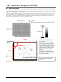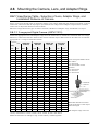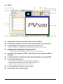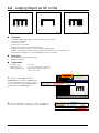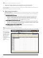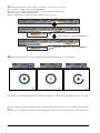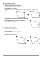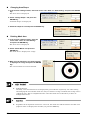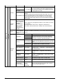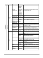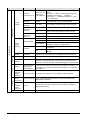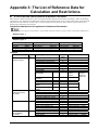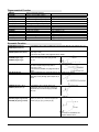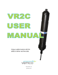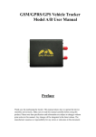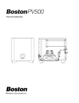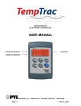
1
[Basic course] Training Text May 2008 Matsushita Electric Works, Ltd. Automation Controls Business Unit Automation Controls Device Division Preface Thank you for selecting or evaluating our Imagechecker PV500 (hereafter "PV500"). PV500 is an image-processing device built on our image processing technology accumulated for many years. PV500 simultaneously achieves ease of use, high speed, and high performance, by complete pursuit of functions and performance based on our customers’ needs and our hands-on experience and expertise. This text is for trainings, such as our FA Seminars, where participants can learn about the functions and basic usage of PV500. It is also useful after introduction for installing and using of PV500. In addition to this text, the following manual is available on PV500: - User's Manual Chapter 1 What is Imagechecker? ........................................................................................3 1.1 Why We Use Imagechecker ......................................................................................3 1.2 Imagechecker Operation Sequence...........................................................................4 1.3 Inspection Images for PV500.....................................................................................5 1.4 PV500 Inspection Procedure .....................................................................................8 Chapter 2 Settings and Basic Operations .............................................................................9 2.1 Connecting Peripherals .............................................................................................9 2.2 Keypad....................................................................................................................11 2.3 Initializing Environment Settings ..............................................................................12 2.4 Initialization of Product Type....................................................................................13 2.5 Initial Settings of Environment .................................................................................16 2.6 Mounting the Camera, Lens, and Adapter Rings......................................................17 2.6.1 View Range Table - Selection of Lens, Adaptor Rings, and Installation Distance of Camera 17 2.7 View Range Setting.................................................................................................19 2.7.1 Capturing Suitable Images for Inspection .........................................................20 2.8 Selecting Type ........................................................................................................22 2.9 About Screen ..........................................................................................................25 2.10 OPERATION window and SETUP window ..............................................................27 2.11 Menus and Functions ..............................................................................................28 2.12 Displayed Image .....................................................................................................31 Chapter 3 Binary Window....................................................................................................33 3.1 Overview.................................................................................................................33 3.2 Judging Object as OK or NG ...................................................................................34 3.3 Measure Area A on Image.......................................................................................54 Chapter 4 Connector (Gray Edge) ......................................................................................73 4.1 Overview.................................................................................................................73 4.2 Measure Width of the Object ...................................................................................75 Chapter 5 Basic Setting of Checkers ..................................................................................83 5.1 Overview.................................................................................................................83 5.2 Checker Number and Checker Type........................................................................84 5.3 Area Setting ............................................................................................................87 Appendix 1: The List of Checkers ........................................................................................95 Appendix 2: The List of Environment Setting.......................................................................97 Appendix 3: The List of Reference Data for Calculation and Restrictions.........................101 Operators and Functions .................................................................................................. 105 Appendix 4: The List of Reference Data for Judgment and Restrictions...........................107 Appendix 5: Error Codes and Error Signals.......................................................................109 Appendix 6: The List of Menus...........................................................................................112 i Chapter 6 Binary Edge ...................................................................................................... 117 6.1 Overview............................................................................................................... 117 Chapter 7 Gray Edge......................................................................................................... 118 7.1 Overview............................................................................................................... 118 Chapter 8 Feature Extraction ............................................................................................ 119 8.1 Overview............................................................................................................... 119 Chapter 9 Smart Matching ................................................................................................121 9.1 Overview............................................................................................................... 121 ii Chapter 1 What is Imagechecker? What is Imagechecker? 1.1 Why We Use Imagechecker "Imagechecker" is the product name of image processing devices produced by Matsushita Electric Works, Ltd. Imagechecker is device for automating and simplifying visual inspections, which had relied on the human eyes. Replacing the human eyes, the devices can inspect the products by processing images taken by cameras. Using cameras provides; Complicated inspections with multiple conditions without touch, those were impossible by optical sensors, proximity switches, or applications of actuators. Imagechecker also provides Stability of inspections because Imagechecker have no obsceneness of the standards, unevenness, instability or carelessness that visual inspections might have. In addition, the device accomplishes High-speed and high-precision inspection that is difficult or even impossible for human eyes Imagechecker at your production facilities will solve your problems with visual inspections such as: • • • • Cutting down the inspection costs Reducing oversights and mistakes Expediting the operations Improving precision 3 1.2 Imagechecker Operation Sequence Imagechecker processes “inspections” set in advance when the external device signals to start. The operation sequence of “inspections” is shown below. Executes checkers with the settings of objective areas and image processing functions. Capture an image Execute an inspection Calculates the setting functions and judges the results. Calculate result OK NG Numerical Data Output to external device 1. Capture an image Capturing a contrasty image is important to allow camera distinguishing the area to inspect. To inspect an image appropriately, you must carefully select not only cameras and lens but also lighting equipment and the way of illumination. It is the hardest but the most important to capture an appropriate image in image processing. 2. Execute checkers A checker is a basic unit for image processing in Imagechecker. PV500 has several types of checkers such as the following: Binary Window counts the number of white or black pixels to measure the black area of the object, and Gray Edge detects coordinates of the edge to measure the length of the object. Each checker outputs individual results. 3. Calculate Most inspections use the results of more than one checker to calculate and judge. Using them, numeric calculations and logical operations lead a final result. 4. Output to external devices Numeric calculation results and judgments can be output to external device through specified interfaces. The PV500 supports the following communications: maximum of 16-bit parallel output, RS-232C serial output, Ethernet, and SD memory card. 4 1.3 Inspection Images for PV500 About Image Data A camera-captured image consists of pixels or the smallest units of an image. PV500 captures an image in 1600 pixels horizontally and 1200 pixels or 640 pixels horizontally and 480 pixels vertically. The number of pixels varies depending on using camera. PV500 uses monochrome cameras and each pixel has 8-bit grayscale value from 0 to 255. Using an image with 256 gradation levels and differences of grayscale levels to contrast each pixel, the gray image processing is strong for brightness changes and allows stable inspections. The example below describes 2-mega-pixel digital camera we will use in this training. 1600 pixels (*) : 1 pixel Brightness information (Gray level): 0 to 255 1200 pixels (*) * When 2-mega camera is used. X-axis Coordinate (0, 0) Rotation θ Y-axis Coordinate (1599, 1199) PV500 has a coordinate system as the left image. X axis is in the horizontal direction and Y axis is in the vertical direction. Rotation angle, theta is clockwise. The coordinate at the upper left of the screen is (0, 0) and the bottom right is (1599, 1199) for 2-mega camera and (639, 479) for ultra compact camera. “X-coordinate” or “Y-coordinate” described in the setting of checkers and inspection results are based on this coordinate system. You can change the positive direction and the original point of axes as necessary. 5 Digital Cameras for PV500 PV500 uses digital cameras instead of analog cameras used by the earlier models. Compared with analog cameras, digital cameras have the features shown below; Insusceptible to external noise Relatively susceptible to external noise Digital signal Analog signal No digitization is required Digitized inside the camera PV500 Less fluctuation of capturing Digitized after it comes in to PV310 Captures at the signal input of PV310 PV310 More fluctuation of capturing Digital camera Analog camera Thanks to these features, digital cameras allow higher precision inspection with its uninsusceptibility to noise and less fluctuation in capturing quality. Camera Type PV500 connects three types of cameras shown in the table below. You can select one of the cameras according to the conditions including size of inspection object, required accuracy, and inspection time. To make setting of connecting camera, select “ENVIRONMENT” > “Camera” and “TYPE” > “Type Setting” > “Camera Setting”. 2-mega-pixel Digital Camera (ANPVC1210) Number of Pixels Image transferring Time Quad-speed Digital Camera (ANPVC1040) Ultra Compact Double Speed Digital Camera (ANPVC1021) 300 thousand pixels (640 x 480) 2 million pixels (1600 x 1200) Approximately 34 ms Approximately 9 ms Approximately 17 ms * This manual describes the cameras as follows. 2-mega-pixel Digital Camera = 2 Mega camera Quad-speed Digital Camera = Quad-speed camera Processing Captured Images PV500 connects up to four cameras (for four-camera type product). And you can use three types of cameras at the same time as necessary. Connecting cameras are Camera 0, Camera 1, Camera 2, and Camera 3, as indicated next to each camera connector of PV500. PV500 has inspection image memories for each camera inside and captured images are stored in the each designated memory (Memory 1 for Camera 1, Memory 2 for Camera 2, Memory 3 for Camera 3). 6 Displayed Image Type PV500 is an image processor for gray scale processing. The device displays camera-capturing images in two types of method, “Gray Scale Image” and “Binary Image”. You can change the type by operating the <F1> key menu, “Memory/Live” > “Gray/Binary”. (When you set checkers, an image on the screen switches between gray and binary; to a gray image in the checkers perform gray processing and to a binary image in the checkers perform binary processing.) What is Gray Scale Image? Captured signals of image data have various level of brightness. PV500 divides the signals in 256 levels of brightness and stores them as an image to display. This image is “gray scale image”. and just like a photo taken with monochrome camera. What is Binary Image? Binary Image is a gray scale image that whitens all pixels within the certain range of gray scale and blackens the rest of pixels. Gray area, which a gray scale image has, does not exist. The gray scale, which divides white and black range, is a slice level. The smaller color information of a binary image that is binary (white and black) information speeds the process of checkers comparing to inspections with a gray scale image. Note that if the brightness of the image or an inspection object changes during inspection, a pixel may change from white to black or black to white. Gray scale image Binary image 7 1.4 PV500 Inspection Procedure The general setting procedure for inspection with the PV500 is as described below. Every step is not always needed and you can skip some steps depending on the condition. (IP address setting) (Calendar setting) PV500 basic settings (Setting data save) Camera connecting, Camera type setting View range setting (focus and aperture adjustment) (Result input/output setting) Environment settings (Communication settings; parallel and serial) Type selection Setting of execution mode and number of blocks Camera capturing setting (shutter speed and gain) Calibration setting Setting of preprocess and slice level Checker setting Product type settings Numeric calculation setting Judgment setting Setting of image save/output Setting save Layout setting/save ● 8 OPERATION window PV500 requires basic settings, such as the setting of calendar and IP address, only once when you install it. Be sure to save them after you modify the settings of [Configuration]. Chapter 2 Settings and Basic Operations Settings and Basic Operations 2.1 Connecting Peripherals Connects the peripherals with PV500 as follows. In this training, we have the following conditions; - Although we will connect PV500 with a PC in the last half, we will not use designated tool software, AXTOOL Ver.3. - We will not use a memory card (SD card). ● Make sure to turn the power OFF for PV500 before connecting. Otherwise, damage might cause. 9 Here is the aspect of setting. Monitor Magnet stand Camera cable 2-mega pixel camera PV500 Lens Ring type white LED Adapter ring Training card Digital power source Keypad Ruler (for confirmation of view range) Flat type white LED (We do not use in this training.) We use training cards for the exercises instead of practical works. (Training cards are in the appendix at the end of this training manual.) To inspect certainly, the objects printed on the training cards are clear and contrasty. However, because the ceiling lighting is generally unstable for adjusting focus or aperture of a camera, we have the special lightings for the training. We have two types of lightings, ring-type white LED illumination and flat-type white LED illumination. We will use the ring-type lighting in the training. (The above picture shows also flat-type lighting for your guidance.) Mount the ring-type lighting between a camera and a work (training card) as the picture. The vertical position of the lighting should not be so strict thanks to the contrast of the training cards; about the lighting position in the picture is appropriate. ● If the lighting is too far from the work, it results in less illumination. (You can adjust the light intensity with the designated digital light controlling power.) ● If the lighting is too close to the work, the camera captures the lighting itself. For trainings, this is enough consideration of lightings. However, in actual inspections, you need more consideration of lighting types and capturing way to capture various works. 10 2.2 Keypad Key operation guide Names and Descriptions 1 ENTER key Cursor Operation To select the menu, input letters and move the start and end points of areas. Determination Operation To determine the settings or select menu. 2 TRIG Key (TRIGGER) To start an inspection or run a test. 3 CANCEL Key To return to the previous window or operation while setting. 4 F1 Key Mainly to display the image menu. 5 F2, F3 Key Use these keys when key guide is displayed in the bottom of the window. 6 OPE/SET Switch To switch windows between SETUP and OPERATION. This is a snap type switch and the window switches every time you snap it. 7 FUNC Key (FUNCTION) To display pop-up menu. Pressing it 2 seconds or more takes a printscreen (screen display copying). 8 SHIFT Key Use when “SHIFT” sign is shown on the screen. Mainly, to make the cursor move faster combining with cursor operation. “SHIFT” sign is shown when you select a Product type or a checker and set an inspection area. To lock or disable the 1 - 8 keys by setting in “LOCK” side. The switch prevents undesired operation of the keys by mistake. In the key operation guide field on the screen, the information whether the following keys can be used and their operations; TRIG key, F1 key, F2key, F3 key, OPE/SET switch, FUNC key, and SHIFT key. 9 LOCK Switch 11 2.3 Initializing Environment Settings We will configure the initial settings of PV500 environment for this training. Environment is the common setting for all product types to make a suitable environment for inspections such as setting of camera or communication. 1. Press the “OPE/SET” key in OPERATION window to display the menu bar. Next, use the right/left arrow keys (← and →) to move the cursor onto "ENVIRONMENT", and then press the ENTER key. 2. Use the right/left arrow keys (← and →) to move the cursor onto "Initialize", and then press the ENTER key. 3. The message below appears. Select "YES" and press the ENTER key. Now, initializing Environment is completed. 12 2.4 Initialization of Product Type Product Type is a group of settings which are necessary to execute an inspection such as image capturing setting of camera, inspection area, and conditions of inspection method. Multiple types can be registered. You can continue inspections simply by switching to the registered type even if you need to inspect on the object with different conditions. The PV500 allows you to save 25600 sets of inspection conditions. You can set a title for each product type. In this chapter, we will initialize and set a product type of PV500 to use in the training. 1. Press the “OPE/SET” key in OPERATION window to switch to SETUP window. Next, use the right/left arrow keys (← and →) to move the cursor onto "TYPE", then press the ENTER key. 2. Use the right/left arrow keys (← and →) to move the cursor onto "Select Type”, and then press the ENTER key. The list of set Product Types appears on the screen. For this training, initialize the all types firstly. 3. Press the CANCEL key to move the cursor onto “Select Type”. Press the right arrow key (→) to select "Initialize", and then press the ENTER key. 4. The message below appears. Select "YES" and press the ENTER key. Initialization of all product types completed. Be sure to save the new settings, otherwise the PV500 clear unsaved settings when the device turns off. Right after initialization, PV500 creates a new type in No.000. Confirm that “000” is shown for Running Type and Setting Type in the information display area. 13 5. Store the setting data in PV500. Move the cursor to “SAVE/READ” and press the ENTER key. Move the cursor to “Save Setting Data” and press the ENTER key. 6. The cursor moves to “Save to”. Confirm that “Main Memory” is selected. Use the up/down arrow keys (↑ and ↓) to the cursor onto the Area No. list and press the ENTER key. Area No. list 7. The cursor moves to “00”. Save the current information in the area of No.000. Press the ENTER key on “00”. The message appears as the right figure. Confirm that the cursor is on “Yes” and press the ENTER key. The settings we set have been saved in PV500, excluding lens aperture and focus. 14 8. Observe the size and date of the saved data in the field of “Size” and “Date” of Area No.00. Plus, confirm that the sign saying “Data updated!” which was shown in the message area disappears. Now, saving the setting data in PV500 is completed. The settings saved in “Save Setting Data” in this chapter are conditions which you set in SETUP and OPERATION windows. Note that these conditions exclude the settings of “TOOL” > “Configuration” in SETUP window. Configuration menu When you change or set the items of Configuration (“Startup Setting”, “Network”, “Calendar”, “Language”, and “Initialize”), the message appears as right figure. To use the changed setting, select “Yes” and press the ENTER key and complete saving. 15 2.5 Initial Settings of Environment 1. Configure initial settings. Move the cursor onto "ENVIRONMENT" and press the ENTER key. Next, use the up/down arrow keys (↑ and ↓) to move the cursor onto "Camera” and press the ENTER key. 2. Move the cursor onto the “Camera” in the dialogue. Confirm that “Connected Camera” of Camera No.0 is displayed as “2 Mega” which is currently connected. 3. Set “2 Mega” for “Camera Type” of Camera No.0. Press the Enter key. In the pulldown menu of Camera No.0, use up/down arrow keys (↑ and ↓) to move the cursor onto “2 Mega” and press the ENTER key. If the types for “Connected Camera” and “Camera Type” are different, PV500 cannot capture an image correctly. Changing camera type initializes capturing conditions of cameras*. It is advisable to set the correct camera types before setting capturing conditions. PV500 makes camera settings at its startup. When you changed the camera mode, you have to save the setting and then reboot PV500. This operation allows capturing an image correctly. *Capturing condition of cameras: the following items can be set from “TYPE” > “Type Setting” > “Camera Setting”; ● Shutter Speed ● Gain, Capture Delay ● Flash Delay (ms) ● Flash Span (ms) ● Partial Imaging ● Calibration As you switch the camera mode, the message appears as the figure below. 16 2.6 Mounting the Camera, Lens, and Adapter Rings 2.6.1 View Range Table - Selection of Lens, Adaptor Rings, and Installation Distance of Camera First, you need to decide range of capturing images (view range). Adjusting the distances between a camera and a lens, and a lens and an object gives you desired view range. Insert adapter rings between a camera and a lens to adjust the distance between them. The View range table lists types of camera and lens, thickness of adapter rings, and distance to object. 2.6.1.1 2-mega-pixel Digital Camera (ANPVC1210) Select the appropriate lens and adapter rings from the table below to match the resolution and view range. Moreover, confirm the distance between the camera and the object. (The values in the table are around the focal point of ∞, except as otherwise noted.) Lens ANPVL502 f=50 mm View range (mm) Ver. Hor. WD Adapter ring ANPVL252 f=25 mm WD Adapter ring ANPVL162 f=16 mm WD Adapter ring Resolution µm/pixel Ver. Hor. 1 1.3 30 264 0.8 2 2.7 40 132 1.7 0.8 1.7 3 4.0 49 88 2.5 2.5 4 5.3 59 66 3.3 3.3 5 6.7 68 53 4.2 4.2 7.5 10.0 92 35 6.3 6.3 10 13.3 115 26 30 13 8.3 8.3 12.5 16.7 139 21 41 11 10.4 10.4 15 20.0 163 18 53 9 12.5 12.5 20 26.7 210 13 77 7 30 40.0 305 9 124 2(*2) 74 2(*5) 40 53.3 399 7 172 2(*3) 104 2 33.3 33.3 50 66.7 494 5 219 2(*4) 135 1.5 41.7 41.7 75 100.0 731 2(*1) 337 2 210 1 62.5 62.5 100 133.3 968 2 456 2 286 1 83.3 83.3 150 200.0 1441 2 693 1 438 0.5 125.0 125.0 200 266.7 1915 1.5 929 1 589 0.5 166.7 166.7 250 333.3 2388 1 1166 1 741 0.5 208.3 208.3 300 400.0 2862 1 1403 0.5 892 0.5 250.0 250.0 350 466.7 3335 1 1639 0.5 1044 0 291.7 291.7 400 533.3 3809 0.5 1876 0.5 1195 0 333.3 333.3 450 600.0 4282 0.5 2113 0.5 1347 0 375.0 375.0 500 666.7 4756 0.5 2350 0.5 1498 0 416.7 416.7 600 800.0 5703 0.5 2823 0 1801 0 500.0 500.0 700 933.3 6649 0.5 3297 0 2104 0 583.3 583.3 800 1066.7 7596 0.5 3770 0 2407 0 666.7 666.7 900 1200.0 8543 0.5 4244 0 2710 0 750.0 750.0 1000 1333.3 9490 0 4717 0 3013 0 833.3 833.3 16.7 16.7 25.0 25.0 Lens focal point differs from the others. *1: Around 2 *2: Around the closest position *3: Around 0.5 *4: Around 1 *5: Around 0.3 WD: The distance from the front of the lens to the object f: Focal length The adapter rings come in a variety of thickness; 0.5mm, 1.0mm, 5mm, 10mm, 20 mm, and 40mm. Make the thickness of “Adapter ring” in the table by combining them. 17 2.6.1.2 Quad-speed Digital Camera (ANPVC1040) (The values in the table are around the focal point of ∞, except as otherwise noted.) Lens View Range (mm) ANM8850 ANM88501 f=50 mm Ver. Hor. WD 1 2 3 4 5 7.5 10 12.5 15 20 30 40 50 75 100 150 200 250 300 350 400 450 500 600 700 800 900 1000 1.3 2.7 4.0 5.3 6.7 10.0 13.3 16.7 20.0 26.7 40.0 53.3 66.7 100.0 133.3 200.0 266.7 333.3 400.0 466.7 533.3 600.0 666.7 800.0 933.3 1066.7 1200.0 1333.3 59 73 87 101 115 150 186 221 256 326 467 608 749 1101 1452 2156 2860 3564 4268 4972 5675 6379 7083 8491 9898 11306 12714 14121 Adapter ring 178 89 59 44 36 24 18 14 12 9 6 2(*2) 2(*3) 2 2 1 1 0.5 0.5 0.5 0.5 0.5 0.5 0.5 0.5 0 0 0 ANB847L f=50 mm WD 48 62 76 90 104 139 175 210 245 315 456 597 738 1090 1441 2145 2849 3553 4257 4961 5664 6368 7072 8480 9887 11295 12703 14110 Adapter ring 178 89 59 44 36 24 18 14 12 9 6 2(*2) 2(*3) 2 2 1 1 0.5 0.5 0.5 0.5 0.5 0.5 0.5 0.5 0 0 0 ANB846NL ANM88251 f=25 mm WD 31 49 66 84 101 137 207 277 348 524 700 1052 1403 1755 2107 2459 2811 3163 3515 4219 4923 5626 6330 7034 Adapter ring 18 12 9 7 6 2(*2) 2(*3) 2 2 1 1 0.5 0.5 0.5 0.5 0.5 0 0 0 0 0 0 0 0 ANB845NL ANB 843L ANM88161(*1) f=8.5 mm f=16 mm WD 31 42 53 76 121 166 211 323 436 661 886 1112 1337 1562 1787 2013 2238 2688 3139 3589 4040 4490 WD: The distance from the front of the lens to the object f: Focal length *1: WD= +4 mm *2: Lens focal point is around the closest position *3: Lens focal point is around the middle position 18 Adapter ring 6 4.5 2(*2) 2(*3) 2 1.5 1 1 0.5 0.5 0.5 0 0 0 0 0 0 0 0 0 0 0 WD 30 54 78 102 162 221 341 461 580 700 820 939 1059 1179 1418 1657 1897 2136 2375 Adapter ring 1.5 1 1 0.5 0.5 0.5 0 0 0 0 0 0 0 0 0 0 0 0 0 ANB 842NL f=6 mm WD 32 49 66 108 150 235 319 404 488 573 657 741 826 995 1164 1333 1502 1671 Adapter ring 1 1 0.5 0.5 0.0 0 0 0 0 0 0 0 0 0 0 0 0 0 Resolution µm/pixel Ver. Hor. 2.1 4.2 6.3 8.3 10.4 15.6 20.8 26.0 31.3 41.7 62.5 83.3 104.2 156.3 208.3 312.5 416.7 520.8 625.0 729.2 833.3 937.5 1041.7 1250.0 1458.3 1666.7 1875.0 2083.3 2.1 4.2 6.3 8.3 10.4 15.6 20.8 26.0 31.3 41.7 62.5 83.3 104.2 156.3 208.3 312.5 416.7 520.8 625.0 729.2 833.3 937.5 1041.7 1250.0 1458.3 1666.7 1875.0 2083.3 2.7 View Range Setting For this training, we use the lens of f=25mm and set the vertical view range to 50mm. Now, make a setting of view range. Excerption of the view range table for 2-mega-pixel digital camera Lens View range (mm) ANPVL502 f=50mm ANPVL252 f=25mm 10 12.5 15 20 30 13.3 16.7 20.0 26.7 40.0 115 139 163 210 305 40 53.3 399 7 172 Adapter WD ring 13 11 9 7 2(*2) 74 2(*3) 104 50 66.7 494 5 219 2(*4) Ver. Hor. WD Adapter ring 26 21 18 13 9 30 41 53 77 124 ANPVL162 f=16mm WD 135 Adapter ring 2(*5) Resolution µm/pixel Ver. 8.3 10.4 12.5 16.7 25.0 Hor. 8.3 10.4 12.5 16.7 25.0 2 33.3 33.3 1.5 41.7 41.7 *2: Le ns focal point is around the closest position *3: Le ns focal point is around 0.5 *4: Lens focal point is around 1 *5: Lens focal point is around 3 WD: The distance from the front of the lens to the object *: Lens focal point differs from the others. Exercise 1 Set a vertical view range to 10mm by referring to the values of “WD” and “Adapter ring” in the view range table to capture an image. The view range table lists WD = 30mm and Adapter ring = 13mm for the 10mm vertical view range with an f = 25mm lens. A set of adapter rings consists of the rings of the following thickness; 40mm, 20mm, 10mm, 5mm, 1mm, and 0.5mm. Combine them to make 13mm-thickness. The camera or the lens and a 10mm-ring can be screwed each other to fix. However, you cannot screw them if rings of over 2mm are between them. Therefore, insert rings of 1mm between the camera and a 10mm-ring, and another ring of 2mm between the 10mm-ring and the lens, to make the total thickness of 13mm. Exercise 2 Set a vertical view range to 50mm by referring to the values of “WD” and “Adapter ring” in the view range table to capture an image. The view range table lists WD = 219mm and Adapter ring = 2mm for the 50mm vertical view range with an f = 25mm lens. (The focal point is around 1.) 19 2.7.1 Capturing Suitable Images for Inspection To have accurate and stable inspection results, you must capture the desired area of the object appropriately. Images out of focus and wholly extremely light or dark images will not achieve accurate inspection results. Image with suitable exposure and focus Out-of-focus image Underexposed image Overexposed image Adjusting Aperture and Focus Generally, a lens has two rings for adjusting. The ring with marks such as 1.4, 2, 2.8, 4, 5.6, 8 ... is the "aperture" ring. The ring with marks such as 0.3, 05, 0.7, 1... ∞ is the "focus" ring. 1. Adjust focus first. To capture suitable images for inspection, adjust the focus of the lens appropriately. Because you can focus more sharply with open aperture, dim the lights before adjustment. Open the aperture so that the captured image has sufficient brightness. Adjust the focus to the point where the camera captures the edge of the object most sharply. 2. Next, adjust the aperture. After adjusting the focus, turn on the lighting device. Then, adjust the aperture so that the entire image is neither too bright nor too dark to capture the target clearly. Adjust the aperture and the focus before all settings including a checker setting. 20 About Image Display PV500 displays camera-capturing images in Screen window. Screen window allows displaying the images zoomed in/out. Thus, the sizes of the displayed image and the captured image are not always the same. Before setting the view range, display the entire captured image on the screen. Note that displaying no scroll bar on the screen. Displaying the scroll bar indicates that the displayed image is a part of the captured image. Be sure to set the view range when you can see the entire image. Refer to page 30 on how to set it. [Captured image] [Screen display] Depending on the magnification, the area displayed on the screen varies even if the same image was captured. Magnification: 30% Magnification: 50% Although magnification changes the display size of an image on the screen, the actual image size does not depends on it; 1600 x 1200 or 640 x 480. Larger magnification may not be able to display an entire captured image on the screen. Only a part of the image is displayed and the scroll bar appears. Moving the scroll bar allow you to observe the hidden part of the image. Magnification: 100% The entire window cannot be displayed and scroll bar is displayed. This part hidden on the screen is also captured by camera. Be sure to aware that hidden part exists if the scroll bar is displayed when setting view range. Hidden part 21 2.8 Selecting Type 1. Create a new product type. Right after initializing all types, PV500 creates a new type in No.000. Press the ENTER key on “TYPE”. Use the right/left arrow keys (← and →) to move the cursor onto "Select Type", and then press the ENTER key. 2. The cursor moves to the type list. In the window of “Select Type”, the type list is displayed. In this window, you can create a new type, switch types and enter a comment. To select the type No. you want to create, use the up/down arrow key (↑ and ↓) to move the cursor. For now, move the cursor onto product type No.001 and press the ENTER key. “Current Type No. 001” is shown above the list. Now, the type is switched to the new one. 3. Name this product type. Choose Type No.001 and press the FUNC key. A menu appears in the top left of the screen. Use the up/down arrow keys (↑ and ↓) to move the cursor onto "Enter Comment” and press the ENTER key. 4. The “Enter Comment” box appears. Enter a product type title using the arrow keys and ENTER key. A Product Type title consists of up to 64 characters. In the right example, “Test_1” is being set. 22 5. After entering it, select "Enter" and press the ENTER key. The title is registered. You can see that the product type list shows the title you have entered. (In the right figure “TEST_1”) 6. Next, we will change the shutter speed. Select “TYPE” > “Type Setting”. Move the cursor onto “Camera Setting” and press the ENTER key. 7. Press the ENTER key in “Common Setting” and select “No (Independent)”. About items of “Common Setting” In PV500, you can set the items of Camera Setting, including a trigger which commands an inspection start and shutter speed of a camera, for each product type. Additionally, you can commonly use them in different types. “Common Setting” decides whether you make setting for each type or use common setting. ”Common Setting” applies to the items beneath it in the “Camera Setting” window. 8. Next, change the shutter speed. Make setting for Camera No.0 (Camera No. to Set: 0). Confirm that “2 Mega” is shown in “Connected Camera”. “Shutter Speed”, “Gain”, “Capture Delay (ms)”. “FLASH delay (ms)”, “FLASH Span (ms)”, “Partial Imaging”, and “Calibration” are setting items per camera. 23 Press the ENTER key on “Shutter Speed”. 9. The menu shown on the right appears to select shutter speed. Switch the speed which is currently set to “10ms” to “5ms”, “1ms”, “500us”, “250us”…. Pressing the ENTER key at the higher speed setting shows the darker image. On the contrary, pressing the ENTER key at the lower speed such as “50ms”, “100ms”, “500ms”, …shows the lighter image. The higher shutter speed darkens a captured image, and the lower speed lightens it up. Slow speed (Light) Fast speed (Dark) About Setting Numbers As you can see in the type list, Type number begins from 000 in PV500. In the same way, the rest of the setting items begin from 0, including Connected Camera number, Screen number, and Checker number. ENVIRONMENT > Camera OPERATION > Layout The number begins from “0”. INSPECTION > Checker The number begins from “0”. Note that all the setting numbers in the earlier models (PV310, AX40, A series, etc.) begin from 1. 24 2.9 About Screen OPERATION 1: Main Menu: Displays the menu to set in OPERATION. 2: Information Display Area: Displays the information of PV. a) Displays the current type, layout No. and the status of the PV500.) b) ReadEnd signal status (image capture completion signal) c) Total judgment result d) I/O terminal status ACCEPT: Available for receiving signals READY: Inspection start ready completion signal STROB: Result read timing TACT: Result read timing ERROR0: Error in executing an inspection or outputting a result ERROR1: Parallel signal command error e) Displays inspection time and cycle in ms unit. 3: Message Area: Displays the message to inform. e.g.) The setting has been changed. > “Data updated!” The voltage of the attached battery became lower > “Change Battery!” 4: Window Type: Displays "OPERATION". 5: Operation Status: Displays the status operating (RUN) or pausing (STOP). 6: Screen Window: This is a window to display an image. In addition, a data R/W window which shows data can be displayed in the area. 7:Key guide: Displays the operations of each key of the keypad. 25 SETUP 1: Main Menu: Displays the menu to make setting in SETUP. 2: Sub-menu: Displays a sub-menu of the menu selected in the main menu. 3: Setting Windows: Displayed in the upper left of the screen. The above image is an example of screen displaying the checker setting window. 4: Message Area: Displays the message to inform. e.g.) The setting has been changed. > “Data updated!” The voltage of the attached battery became lower > “Change Battery!” 5: Window Type: Displays "SETUP". (Indicates the current window is SETUP window.) 6: Operation Status: Displays the status operating (RUN) or pausing (STOP). 7: Information display area: a) Running Type No., Type name, Setting Type No., Type name b) Total judgment of Running Type/ Total judgment of Setting Type c) ReadEnd signal status (image capture completion signal) d) Displays inspection time and test time in ms unit. 8: Screen Window: Displays a camera image. 9: Key Guide: Guide for the keypad 26 2.10 OPERATION window and SETUP window PV500 has two windows; OPERATION window for performing inspections and SETUP window for making settings such as inspection conditions. Operate the device switching between them. OPERATION window This is a window for performing inspection. The PV500 starts in this mode when you turn it on. In OPERATION window, the following items can be operated other than inspections; selecting type, resetting statistics, setting screen layout, saving setting data, viewing PV500 information, and modifying data from Data R/W Window. Regardless of the operation status, RUN or STOP, you can operate these menus. SETUP window In this mode, you can configure or change the settings for all the options in the menu bar (ENVIRONMENT, TYPE, INSPECTION, SAVE/READ, and TOOL). As a default setting, switching to SETUP window stops operation. You can change the setting to operate in SETUP window as well. About Operation Status: RUN and STOP In both of OPERATION and SETUP windows, the monitor shows a sign of “RUN” or “STOP” in the upper right. The operating status is displayed in the field. STOP When PV500 in “STOP” status where it stops operation, you can only set up regardless of OPERATION window or SETUP window. All signals from external device including the inspection start signal (START) are denied. Although pressing the TRIG key on the keypad performs a test, results will not be output to the external device. Run When PV500 in “RUN”, you can execute inspections and output the results to the external device. Only in RUN mode, the PV500 outputs READY signal and accepts signals from the external device including inspection start signal (START). In addition, the inspection results can be output to the external device according to the conditions of communication and output. Switching between OPERATION and SETUP Pressing the OPE/SET key switches between the two windows. (Switching from the SETUP to OPERATION is available only when the screen shows no setting windows). Note that you cannot switch the screen from SETUP to OPERATION if the type of the actually connecting camera and the settings of “Connected Camera” and “Camera Type” in Camera menu of ENVIRONMENT are not the same. Differences between operations in RUN and STOP START signal input Capture an image Execute checkers Calculates a result Output to the external devices RUN STOP No output to the external devices ● As the default setting, product number is 000 at startup. To specify a type number at startup or change it to the type number you have selected right before you turned off PV500, make setting from “ENVIRONMENT” menu. “ENVIRONMENT” > “Condition” > “Startup Setting” > “Type No.” 27 2.11 Menus and Functions Screen at startup OPERATION window Switch with OPE/SET switch OPERATE: To switch items on operation VIEW: To set displaying screen layout LAYOUT: To register and switch layouts TOOL: To save data and show information of PV500 LAYOUT This is the setting about size, number of screens and camera type for screens and data R/W windows. 28 SETUP window OPERATE: Switches operation ENVIRONMENT: Common setting for all product TYPE: Setting necessary for inspections INSPECTION: Sets each inspection condition SAVE/READ: Saves or reads setting data and images TOOL: Sets and Shows the information of PV500 Operations of Imagechecker and Main Settings The diagram below shows the setting items described in page 3 to operate Imagechecker. Capture an image Calculate a result -Environment (Camera) -Type (Camera Setting) - Inspection (Numerical Calculation Execute checkers - Inspection Output to the external device - Inspection (Judgment) - Environment (Input/Output) - Tool (Configuration) Screen of OPERATION window 29 Checker area Displays inspection areas of set checkers. Total Judgment Judgment Calibration scale You can use the detected data in arbitrary unit in calculations specifying a point as an origin. Data R/W This table shows results of inspections and calculatitons in OPERATION. To switch between showing and hiding the checker area and the calibration scale in the figure above, follow the procedure described below. 1. Press the F1 key. 3. Set with this menu. The key guide shows “F1: Select Window” in OPERATION window. 2. Select a screen you want to adjust on the displayed menu. 30 To switch the display of calibration scale and checker area, select "Pattern Display". 2.12 Displayed Image Two types of images are selectable when displaying captured images on the monitor. To select image types, press the F1 key and select “Memory/Live” in the displayed menu. Option Displayed Image Type Live image The current image. An image changes in real-time. If the lens is covered with your hands, a blacken image will be captured. Memory image The image stored in a memory for inspection. Unlike a live image, the images do not change in real-time. For inspections with Imagechecker, you should use memory images. On the other hand, live images help to make settings, such as focus adjustment and aperture adjustment, thanks to their feature that they change in real time. Switching between Live/Memory Press the F1 key when the key operation guide which is on the bottom of the screen shows “Image Menu” or “Select Window” for the F1 key. A menu for display image setting appears. Select “Memory/Live” and press the ENTER key. A menu to switch a display image appears as shown on the right. You can switch a display image by selecting “Memory/Live”. To find the display image Memory or Live, confirm the title bar on top of the screen. The figure below shows the title bar when the display image is switched from Live to Memory. The title is switched from “Live” to “Memory”. About Other Image Menu An image captured with the connecting camera is displayed on the Screen window. You can choose a camera image and an image type to display. “Image Menu” is to set them. Press the F1 key to display the menu. There are four main functions in Image Menu; 1: Setting for screen display 2: Size adjustment of an image displayed on the screen 3: Reading and saving of an image 4: Adjustment of size and position of the screen 31 The table below lists details of the functions. 1: Setting for screen display To select a camera to capture an image displayed on the screen. Select Camera Select how to display a captured image in "Memory/Live”, “Gray/Binary”, and “Preprocess”. To select Live or Memory for an image displayed on the screen. Memory/Live Gray / Binary To select Gray or Binary for an image displayed on the screen. Preprocess To select to display preprocessed image or not. To select display the support tools (Marker, Calibration scale, Checker pattern) or not. 2: Size adjustment of an image displayed on the screen When displaying a zoomed in image, only a part of image can be shown. To Scroll show the nondisplayed part, use the scroll function. To display a camera image zoomed in/out. Magnification To display an image in full size of the screen. Full Screen Pattern Display 3: Reading and saving of an image (only for SETUP window) To save images stored in the Image Memory of PV into a SD memory card. Save Image (About Image Memory, see the figure below/) To read images in Image Memory of PV500 or Test Image and Image Memory of a SD memory card as images for inspection. Read Image (In the figure below, Image Memory, Test Image, and SD Image Memory are marked with *. 4: Adjustment of size and position of the screen (only for OPERATION window) To move a screen window and a data R/W window displayed on Move Window OPERATION window. To change the size of a screen window and a data R/W window displayed Change size on OPERATION window. To change the size and magnification of a screen window displayed on OPERATION window into the optimum size. Optimize size Connected camera: 2-mega camera -- Magnification: 50% Connected camera: Quad-speed camera, Ultra compact camera -Magnification: 100% PV500 saves camera-capturing images in PV500, a SD memory card, or PC. Some of the saved images can be read out. Images can be saved in the destinations described in the table below. Destination of images, Saving images, and Menu to operate Destination PV500 - Image Memory Test image Saving Image Menu to operate Images captured in RUN (Turning off the power deletes them.) The last image captured in OPERATION window. (Saved when switching to SETUP window.) ENVIRONMENT > Input/Output > Save Image Memory SD image memory Images captured in RUN PC (Image Receiver) Images captured in RUN 32 ENVIRONMENT > Condition > Operation ENVIRONMENT > Input/Output > Image Output ENVIRONMENT > Input/Output > Image Output Chapter 3 Binary Window Binary Window 3.1 Overview What Is Binary Window? Binary Window is a function that counts the number of black and white pixels in a binary image. If the number of counted pixels is within the allowable range, the object will be judged as "OK", if it exceeds the allowable range, the object is judged as "NG". Area shape Mask area The Range of Measurement Results Rectangle/Circle/Polygon (The number of settable vertices: 3 to 64) The Number of Settable Mask Areas: Up to 16 0 to 1920000 (2-mega-pixel camera), 0 to 307200 (Quad-speed camera) Menu Options 33 3.2 Judging Object as OK or NG [OK] [NG 1] [NG 2] Overview 1: Create a Binary Window to measure the area of an object. 2: Create a comment. 3: Set a slice level. 4: Set an area to inspect. 5: Measure the area of OK and NG objects. 6: From the results of step 5, set the range to judge objects. 7: Make a judgment setting to output judgment results to the external devices. 8: Set a Total Judgment to see the judgment result at a glance. Exercise 1 Binary Window (Rectangle setting) Judgment setting Preparation Product type Training Card Image preparation : No. 000 : No.1, No.2, and No.3 (3 cards) : Capture Training Card No.1. Live, C0, Gray 1. Press the “OPE/SET” switch in OPERATION to switch to SETUP. Next, use the right/left arrow keys (← and →) to move the cursor onto "INSPECTION”, and then press the ENTER key. 2. Use the right/left arrow keys (← and →) to move the cursor onto "Checker”, and then press the ENTER key. 34 チェッカの番号 Then, the cursor moves to “Checker Type” field. The list of checker is displayed on the screen. 3. Press the ENTER key on “Checker Type”. The checker select box appears. Use the up/down arrow keys (↑ and ↓) to move the cursor onto "Binary Window” and then press the ENTER key. 4. Move the cursor with the up/down arrow keys (↑ and ↓) onto “Checker No.” Press the ENTER key and set “00”. And then press the Enter key again. 5. Move the cursor with the down arrow keys (↓) to the checker select list. Press the ENTER key to move the cursor to “000”. Press the ENTER key again to show the Binary Window setting window. 35 6. Check that the image displayed on the screen was changed to a binary image. This binary image is displayed based on the slice level selected by the setting checker. Binary Window checker setting window Binary image 7. Set a checker name in “Comment”. Select "Area Setting" and press the ENTER key. Move the cursor on "Comment" and press the ENTER key. The window for entering a comment appears. For this training, set “AREA”. After entering letters, select "Enter" and press the ENTER key. Press the ENITER key on “Enter”. 36 8. The cursor goes back to the checker setting window. Confirm that “AREA” is shown in “Comment”. 9. Set a slice level. Press the CANCEL key to move the cursor to “Area Setting”. Then, use the down arrow keys (↓) to move the cursor onto "Inspection Condition" and press the ENTER key. 10. Select a slice level group and set it. Use the up/down arrow keys (↑ and ↓) to move the cursor onto "Slice Level” and then press the ENTER key. 11. Slice level selecting box, slice level list, and a graph are displayed. Use the up/down arrow keys (↑ and ↓) to move the cursor to the center table (Slice level list) and then press the ENTER key. The table shows upper and lower values that are set for each slice level group A to H. The graph shows distribution of brightness of the image on the screen. Brightness dispersion can be seen on the graph. 12. Select A group and press the ENTER key. The slice level setting window for group A is displayed. 37 There are two ways to set a slice level, manual and automatic. First, execute the automatic setting. Use the up/down arrow keys (↑ and ↓) to move the cursor onto "Auto Adjustment” and then press the ENTER key to adjust them. <ENTER> Check that the Lower value field of the setting window shows a new value and the Lower value of group A in the table is updated. 13. Pressing the CANCEL key close the menu and the values are fixed. 14. If auto adjustment cannot binarize the desired object, set slice level manually. Select slice level group A and press the ENTER key. To set it manually, select values of “Upper” and “Lower” and change them to be suitable. We will set a lower value for an example for this training. Select "Lower" and press the ENTER key. The cursor moves to the value field. Adjust the values with the up/down arrow keys (↑ and ↓) to set the slice level so that you can clearly distinguish between the object and the background. Decreasing the lower value makes the entire screen lighter. In contrast, increasing it makes the screen darker. Set a suitable value and press the ENTER key. 38 <ENTER> Now, manual setting of a slice levels is complete. Press the CANCEL key to close the Upper/Lower values setting window. And then, press the CANCEL key twice to close the slice level setting window. 15. Next, we will set an inspection area. The figure below is appearance of Area setting Set an area surrounding the object. Area setting can be operated by the menu of “Area Setting”. Press the CANCEL key to move the cursor onto “Inspection Condition”. Next, use the up/down arrow keys (↑ and ↓) to move the cursor onto "Area Setting” and press the ENTER key. 16. Use the up/down arrow keys (↑ and ↓) to move the cursor onto "Area” and press the ENTER key. (Pressing the CANCEL key at the time cancels the area setting.) 39 17. The inspection area is displayed in green. Set size and position of this area. Check to make sure that the cursor is on “Change” menu in the information display area on the left of the screen. Press the ENTER key. Inspection area 18. The area on the screen changes its color from green to orange indicating you are in “Area Shift” mode. In this mode, you can move the entire area by using the arrow keys (↑, ↓, ←, and →). Move the area to the desired position, then press the ENTER key. (To cancel the moving, press the CANCEL key instead of the ENTER key.) Start point End point Area Shift mode While you are setting an area, SHIFT sign is displayed on the lower right as the right figure. Pressing the arrow keys and the SHIFT key on the keypad at the same time moves the area faster in the direction. 19. The end-point of the area disappears and only the start-point is displayed, indicating you are in "Start-point Set Mode". In this mode, you can move the start point by using the arrow keys (↑, ↓, ←, and →). Move the start point to the desired position, then press the ENTER key. (To return to "Area Shift" mode, press the CANCEL key instead of the ENTER key.) Start Point Set mode 40 20. The start point of the area disappears and only the end point is displayed, indicating you are in "End-point Set Mode". In this mode, you can move the end point by using the arrow keys (↑, ↓, ←, and →). Move the end point to the desired position, then press the ENTER key to decide the area size. (To return to "Start Point Set" mode, press the CANCEL key instead of the ENTER key.) End Point Set mode 21. The rectangles representing the start point and the end point disappear and the cursor moves to “Angle” in the information display area. Now, you are in “Angle Set” mode. In this mode, pressing the up arrow key (↑) rotates the area around the center of it clockwise. Pressing the down arrow key (↓) rotates it counterclockwise. Set the angle and press the ENTER key to decide the setting. (To return to "End Point Set" mode, press the CANCEL key instead of the ENTER key.) Angle Set mode Rotatable within +/- 45-degree 22. The inspection area is displayed in green again. Pressing the CANCEL key finishes area setting. The cursor goes back to the previous window. The area is displayed in green 41 23. Because the object is black, measure the black area. Set the inspection target to black. Move the cursor onto “Inspection Condition” and press the ENTER key. Use the up/down arrow keys (↑ and ↓) to move the cursor onto "Target” and then press the ENTER key to select it. Use the up/down arrow keys (↑ and ↓) to move the cursor onto "Black” and press the ENTER key to decide. 24. Execute an inspection and see. Press the TRIG key. Test is carried out once. Check the area detected by the Binary Window and execution time displayed on the left of the screen. 42 25. Now, we will create the program to judge the object as which of OK or NG according to the inspection result. Set the checker to judge as OK if the area of the object is within the certain range, and to judge as NG otherwise. For each training card (one OK card and two NG cards), measure the area size five times (press the TRIG key five times each) and write down the results in the table below. Card OK object (Card No.1) Target Image Measured Area Size Minimum Maximum NG object (Card No.2) NG object 2 (Card No.3) 26. After writing down the result, complete the table below based on the data. Enter the obtained values in "OK Judge. Max." and "OK Judge. Min." in “Judgment Condition” menu. NG object 1 OK object Min. Min. Max. NG object 2 Max. Average OK Judge. Max. Min. Max. Average OK Judge Min. You cannot set a maximum value below a minimum value, or a minimum value above a maximum value. To set a maximum value below the current minimum value, make the minimum value smaller before changing the maximum value. 27. About entering a value, refer to the example described below. • • Use the right/left arrow keys (← and →) to move the highlighted cursor onto a desired digit. Use the up/down arrow keys (↑ and ↓) to increase or decrease the values. Operation Example 1: Changing 4000 to 5000 004000 <→><→><↑> 005000 Operation Example 2: Automatic Shifting Up and Down 000590 <↑> 000600 000320 <↓> 000319 43 Operation Example 3: Changing 4000 to 7900 004000 <→><→> 004000 <↑><↑><↑><↑> 008000 <→> 008000 <↓> 007900 <ENTER> Operation Example 4: Changing 4000 to 202 004000 <→><→> 004000 <↓><↓><↓><↓> 000900 <↓> … <↓> 000200 <→><→><↑><↑> 000202 <ENTER> 28. After entering the values of OK Judge. Max. and Min., run a test on each card. Observe that "Judgment" displayed above the “Area” value shows “OK” for an OK object and “NG” for an NG object. 29. It is inconvenient that you must close the setting window every time you observe the object while the inspection condition menu hides it. PV500 has functions that temporarily display the screen in the front, or display a captured image in zoomed in size on the screen. Now use this function. Pressing the F1 key shows the screen in the front and a box as the right figure appears. This menu box helps to select often-used commands, such as • Switching between memory image and live image • Switching between binary image and gray scale image • Switching between display and hide calibration scale • Changing image magnification On the bottom of the screen, the current operation keys and their functions are displayed. Press them as necessary. 30. The right figure shows the screen when “Calibration Scale” in “Pattern Display” is set to “Valid”. Calibration scale is displayed. 44 31. Make a judgment of an inspected result by the Binary Window checker we have set. What Is Judgment? PV500 has a function that totally judges on the judgments (OK or NG) of checkers and numerical calculations. Judgment can be displayed on the screen and output to the external devices through parallel and serial communication or to a SD memory card. In addition, according to the judgment, images can be saved and output to the external devices. Up to 1000 formulas can be set for each product type in PV500. In this exercise, we will configure the judgment function to output a signal from OUT0 if the Binary Window we have named “AREA” judges as OK, and from OUT1 if it judges as NG. 32. Use the right/left arrow keys (← and →) to move the cursor onto "Judgment”, and then press the ENTER key. The setting window as shown on the right is displayed on the screen. 33. Use the right/left arrow keys (← and →) to move the cursor onto "Type”, and then press the ENTER key. The menu for selecting “JDC (External)” or “JRC (Internal)”is displayed. “Type” is a setting for selecting whether PV500 outputs a judgment (OK or NG) to the external device or not. To output, select “JDC (External)”, and not to output, select “JRC (Internal)”. For now, to output a judgment of the Binary Window checker to the external device, select “JDC (External)”. 45 34. We will set an operation expression. You need to register a conditional expression in the expression list to output a judgment. The expression outputs (parallel signal: ON) the object judged as OK when Imagechecker is executed. As opposed to that, it does not output (parallel signal: OFF) when the judgment is NG. Thus, you need to set expressions so that JDC000 turns on when you want to output to OUT0 and JDC001 turns on to output OUT1. Expression List First, set an expression in JDC000 to output from OUT0 when the Binary Window named “AREA” judges the object as OK. Move the cursor onto the expression list and press the ENTER key. The cursor moves to “Expression” field in the list. 35. Move the cursor with the up/down arrow keys (↑ and ↓) onto “Expression” of JDC000 and press the ENTER key. Expression setting window appears as the right figure. Now, we will enter an expression in “Expression” field. Press the ENTER key in “Expression”. The cursor moves into “Expression” field. Press the ENTER key. 46 36. The list of items that can be registered in a calculation is displayed. Use the up/down arrow keys (↑ and ↓) to move the cursor onto "Checker” and then press the ENTER key. 37. Select a checker type to use. Use the up/down arrow keys (↑ and ↓) to move the cursor onto "Binary Window” and then press the ENTER key. 38. A window to select a checker number to refer is displayed. Use the up/down arrow keys (↑ and ↓) to move the cursor onto Checker No. list and press the ENTER key. The cursor moves into the table. Because we have already set checker No.000, its name “AREA” is displayed. Confirm that a judgment of the selected checker is displayed. The screen shows the inspection area of the selected checker in orange. The area of Binary Window checker No.000 is displayed in orange. 47 39. Press the ENTER key while the cursor is on “AREA” of checker No.000 in the list. Automatically an expression is set. BWC000_JUDGE: Judgment of Binary Window No.000 40. Press the left arrow key (←). The cursor moves onto “BWC000_JUDGE”. The description of the selected expression is displayed in "Expression Description" field. Confirm that it says “Binary Window No.000 Judgment”. 48 <←> key 41. After setting the expression, enter a comment for it. Press the CANCEL key while the cursor is in the Expression field. Press the up arrow key (↑) to move the cursor into “Comment” and then press the ENTER key. The window for entering a comment appears. Enter "AREA_OK" and press the ENTER key on “Enter”. 42. Pressing the CANCEL key shows a message saying “Register?” Press the ENTER key on “Yes” to finish registering. Confirm that the expression list shows the expression in “Expression” and the set string in “Comment”. 49 43. Judgment of the expression JDC000 is output to OUT0. (* PV500 outputs the judgment when it is operating as you execute an inspection.) 44. In the same way, make a setting to output to OUT1 when a judgment is NG. JDC001 is supposed to output when the Binary Window named AREA judges the object as NG. In Judgment, parallel signal turns on when executing the expression set in JDCXXX outputs OK. Now, we use a negation operator (/) in judgment expression of the Binary Window (AREA). Then, select the Binary Window No.000 named AREA again. JDC001 = / BWC000_JUDGE Setting the expression gives “NG” judgment when AREA outputs OK because it negates “OK”. Conversely, when AREA outputs NG, the expression gives “OK” because it negates NG. In this case, parallel signal turns on and is output. (In the right figure, the comment of JDC001 is set to “AREA_NG”.)) 50 45. Set Total Judgement to find an inspection OPERATION window result at a glance. What Is Total Judgment? Total Judgment is a judgment displayed in the status display area in OPERATION or SETUP window. It can be output to the external devices solely. You can display large signs in green if the result is OK, in red if it is NG in the display field as the right figure. Display field Each product type can apply one of judgment expressions (JDC(External) and JRC (Internal)) as a Total Judgment. Now, we set to display “OK” sign when the Binary Window “AREA” outputs OK. Because JDC000 meets this condition, set it as “Total Judgment”. SETUP window Display field To set a total judgment, select “Condition” in the judgment setting window. Select "Condition ― Setting” and press the ENTER key. 51 46. The setting window for condition is displayed. Press the ENTER key on “Condition” of “Total Judg.” Use the up/down arrow keys (↑ and ↓) to move the cursor onto “JDC” and press the ENTER key. Use the right arrow key (→) to move the cursor onto "Checker No.", and then press the ENTER key. Specify “000” and press the Enter key. After setting is complete, press the CANCEL key to close the setting window. 47. The cursor goes back to the judgment setting window. The information of total judgment is displayed in the lower part of the setting window. 52 48. Run the inspection on OK and NG objects and verify that the screen shows judgment results correctly. You should see that the total judgment is displayed as a green OK-sign for an OK object and a red NG-sign for an NG object. In addition, the checker pattern of the Binary Window turns to green when the object is OK and to red when it is NG. Moreover, verify that signals are correctly output from the parallel ports by viewing Output status monitor. Output status of signals 53 3.3 Measure Area A on Image Circle B Circle A [OK 1] [OK 2] [NG] Overview 1: Create a Binary Window No.000 to measure the sum of the area of Circle A and B. 2: Create a Binary Window No.001 to measure the area of Circle B. 3: Subtract the result of Step 2 from the result of Step 1 to obtain the area of Circle A. Exercise 2 Binary Window (Circle setting) Binary Window (Circle setting for Circle B) Numeric Calculation Setting Preparation Product type Training Card Image preparation : No. 001 : No.4, No.5, and No.6 (3 cards) : Capture Training Card No.4. Live, C0, Gray チェッカの番号 1. Create a new product type. Press the “OPE/SET” switch in OPERATION. Move the cursor onto “TYPE”, press the ENTER key, select "Select Type”, and then press the ENTER key. Select Type No.001 and press the ENTER key. The list shows Common Setting: Yes, Comment: No Name. Check that it shows “Current Type No.: 001”. Now, the type is switched to the new one. Press the CANCEL key to return to the main menu. 54 <ENTER> 2. Use the right/left arrow keys (← and →) to move the cursor onto "INSPECTION”, and then press the ENTER key. 3. Use the right/left arrow keys (← and →) to move the cursor onto "Checker”, and then press the ENTER key. Then, the cursor moves to “Checker Type” field. Press the ENTER key in “Checker Type” box. Use the up/down arrow keys (↑ and ↓) to move the cursor onto "Binary Window” and then press the ENTER key. 4. Move the cursor with the up/down arrow keys (↑ and ↓) onto “Checker No.” Press the ENTER key to set “00” and then press the Enter key again. 5. Move the cursor with the down arrow keys (↓) to the checker select list. Press the ENTER key to move the cursor to “000”. Press the ENTER key again to show the Binary Window setting window. 55 6. Check that the Binary Window checker setting window image displayed on the screen was changed to a binary image. This binary image is binarized based on the slice level selected by the setting checker. Binary image 7. Set a checker name in “Comment”. Use the up/down arrow keys (↑ and ↓) to move the cursor onto "Area Setting” and then press the ENTER key. Use the up/down arrow keys (↑ and ↓) to move the cursor onto "Comment” and then press the ENTER key. The window for entering a comment appears. For this training, enter “AB-AREA”. After entering a string, select "Enter" and press the ENTER key. 8. Set a slice level. Use the down arrow keys (↓) to move the cursor onto "Inspection Condition" and press the ENTER key. 56 9. Select a slice level group and set it. Use the up/down arrow keys (↑ and ↓) to move the cursor onto "Slice Level” and then press the ENTER key. 10. Use the up/down arrow keys (↑ and ↓) to move the cursor to the table on the center (Slice level list) and then press the ENTER key. The table shows upper and lower values that are set for each slice level group A to H. Select group A and press the ENTER key. The slice level setting window for group A is displayed. There are two ways to set a slice level, manual and automatic. First, execute the automatic setting. Use the up/down arrow keys (↑ and ↓) to move the cursor onto "Auto Adjustment” and then press the ENTER key to execute. <ENTER> Check that the Lower value field of the setting window shows a new value and the Lower value of group A in the table is updated. 11. Pressing the CANCEL key closes the menu and the values are fixed. 57 12. If auto adjustment cannot binarize the desired object properly, set slice level manually. Select slice level group A and press the ENTER key. Set a suitable value and press the ENTER key. Press the CANCEL key to close the Upper/Lower values setting window. And then, press the CANCEL key twice to close the slice level setting window. <ENTER> 13. Next, we will set an inspection area. Area setting can be operated by the menu of “Area Setting”. Press the CANCEL key to move the cursor back to “Inspection Condition”. Select "Area Setting” and press the ENTER key. Move the cursor with the up/down arrow keys (↑ and ↓) onto “Area (Set)”. Press the ENTER key. 14. Select a circle shape of the inspection area to adjust the object shape. Use the up/down arrow keys (↑ and ↓) to move the cursor onto "Change Shape” and then press the ENTER key. 58 15. A box of list of shapes to change appears. (Rectangle, Ellipse, Circle, and Polygon) You can draw a circle with either of “Ellipse” and “Circle”. Although both shapes allow drawing a circle, we will use “Ellipse” here to go through how to operate the cursor to draw a shape. Select "Area Display". Use the up/down arrow keys (↑ and ↓) to move the cursor onto "Ellipse” and then press the ENTER key. The checker shape which has been a rectangle changes to an ellipse. Is the rectangle changed into ellipse on your screen? 16. Use the up/down arrow keys (↑ and ↓) to move the cursor onto "Change” and then press the ENTER key. The color of the checker shape turns from green to orange and a rectangle surrounding the ellipse (circumscribing rectangle) appears. 59 17. Set the inspection area to enclose the outer circle as the figure on the right. The setting procedure is all the same as the procedure for a rectangle. Area shift Start point End-point mode setting mode setting mode → <ENTER> → → <ENTER> → ← <CANCEL> ← ← <CANCEL> ← After setting a start point and an end point, leave the Angle ”0.00” and press the ENTER key. Pressing the CANCEL key finishes the area setting and the cursor goes back to the previous window. 18. Press the CANCEL key and use the up/down arrow keys (↑ and ↓) to move the cursor onto “Inspection Condition”, and then press the ENTER key. Use the up/down arrow keys (↑ and ↓) to move the cursor onto "Target”. Select “Black” and then press the ENTER key again. The inspection target is changed to “Black”. Then, pressing TRIG key runs a test once. Check the area detected by the Binary Window and execution time displayed on the Binary Window setting window. <TRIG> Now, we have measured the sum of the area of Circle A and B. Press the CANCEL key twice to move the cursor to list of Binary Window. 60 19. Next, we will create another Binary Window to obtain the area of Circle B. This time, we will create the checker by copying and pasting the Binary Window we have created. Select the Binary Window No.000 and press the FUNC key. A box with options to delete, copy, or paste a checker appears. Use the up/down arrow keys (( and () to move the cursor onto "Copy" and press the ENTER key. 20. Use the up/down arrow keys (( and () to move the cursor onto a copy destination number (Use No.001 for this exercise), then press the FUNC key. The box with options to delete, copy, or paste a checker reappears. Because we have registered nothing for Checker No.001 yet, you can select only the "Paste" command. Press the ENTER key on “Paste” to paste the Checker No.000 settings.. After pasting the checker, the screen shows as follows. When you have not set a comment for the checker, the list shows “No Name”. When you have set a comment for the checker, also the comment is copied and pasted. “NG Filter” is a function that displays only the checkers of which the result is NG from No.000 to No.999. Using this function allows you revise the checkers outputting NG immediately. 21. Make setting of the pasted checker. Press the ENTER key on No.001 “AB-AREA”. Select “Comment” in “Area Setting”. Edit the comment “AB-AREA” to “B-AREA”. After editing, select “Area” to change the inspection area. (About how to create a comment, refer to Step 6, 7, and 8 in the previous chapter.) 22. Modify the inspection area of checker No.001 obtaining the area of the inner circle as the right figure. The inspection area set earlier is displayed in gray circle on the screen. After changing, press the TRIG key. Test is carried out once. Have you measured the area of Circle B? 61 23. Here is a summary of the exercise at this point. • • Configurations of Binary Window No.000 (specifying the area, slice level, and target). Configurations of Binary Window No.001 (copying No.000 and specifying the area). You can obtain the area of Circle A by subtracting the area given by Binary Window No.001 from the area given by No.000. Now, how can we program a subtraction in PV500? What Is Numerical Calculation? Numerical Calculation is a function that calculates the data detected by checkers and outputs the data to the external devices. The area of Circle A can be calculated by using numerical calculation. The numerical calculation has the following main functions; Executing numerical calculations Executes calculations, including four arithmetic operations, trigonometric operations, and geometric operations. Up to 1000 functions can be set per Product Type. Statistics data of “Checkers”, “Position Adjustment”, “Area Size Adjustment”, “Numerical Calculation”, and “Judgment” can be includes in the expression. The statistics data can use only the values gathered in OPERATION and the values in STOP status are invalid. Making judgments on the calculation result The numeric calculations are judged according to the acceptable range for OK judgment that you have set. If the results of the numeric calculations are within the range, it is judged as “OK; otherwise, “NG”. The maximum value of this range is "OK Judgment maximum value" and the minimum value is "OK Judgment minimum value". Outputting inspection results to external devices To output inspection results to external devices, you need to make setting from “ENVIRONMENT” > “Input/Output”. 24. Now, we will set a numerical calculation expression. Use the right/left arrow keys (← and →) to move the cursor onto "Num. Calcu.” and then press the ENTER key. The cursor moves onto "Checker No." Press the ENTER key and set “00”. And then press the Enter key again. Move the cursor with the down arrow keys (↓) to the numerical calculation select list. 62 25. Press the ENTER key. On "Expression" of “CAC000”, press the Enter key again. Expression setting window appears as the figure below. Use the up/down arrow keys (↑ and ↓) to move the cursor onto "Comment” and then press the ENTER key. For “Comment”, set “A-AREA”. (Refer to Step 7 in the previous chapter on how to set it.) <ENTER> <ENTER> twice 26. Use the up/down arrow keys (↑ and ↓) to move the cursor onto "Expression” and then press the ENTER key. The list of items that can be registered in a calculation is displayed. 63 27. Select "Checker" and press the ENTER key. The cursor moves to “PAC(Position Adjustment)”. Use the up/down arrow keys (↑ and ↓) to move the cursor onto "BWC(Binary Window)” and then press the ENTER key. <↑> <↓> 28. The list of Binary Window checkers is displayed. To subtract the area of Circle B from the area of Circle A and B, select the Binary Window measuring the area of Circle A and B first. Use the up/down arrow keys (↑ and ↓) to move the cursor onto No.000 "AB-AREA” and then press the ENTER key. Result type list appears as the right figure. Select "Area” to input and press the ENTER key. <ENTER> “Result” and “Statistics” are displayed. Check that the referred area of the Binary Window is displayed. Select “Result” and press the ENTER key. 64 Check that the set area is displayed in “Result” field. The area detected by Binary Window No.000 is registered. <ENTER> 29. Next, we will set a subtraction. Pressing the ENTER key displays the list of items that can be registered in a calculation. With the up/down arrow keys (↑ and ↓) and the ENTER key, select “Operator” > "-” and then press the ENTER key. 30. Next, we will register the Binary Window measuring the area of Circle B in the expression. Make setting in the same way as the previous one. Press the ENTER key and select “Checker” > "BWC(Binary Window)” and then press the ENTER key. As the list of Binary Window checkers appears, press the ENTER key on No.001 “B-AREA”. Press the ENTER key again on “Area”. Select “Result” and check the value is displayed. Then press the ENTER key. <ENTER> <ENTER> 65 31. Now, the expression obtaining the area of Circle A is complete. Check this expression is correct or not. <←> Move the cursor with the left arrow key (←) to select the item. The expression description field shows the set information, checker No. and result type. Moving the cursor further with the left arrow key (←) shows “Subtraction” and “Binary Window No.000 Area”. 32. After confirming the expression, register it. Press the CANCEL key twice. A message saying “Register?” appears. Choose "YES" and press the ENTER key. The expression below is registered. CAC000=BWC000_AREA - BWC001_AREA BWC000-AREA: Binary Window No.000 (Area) BWC001-AREA: Binary Window No.001 (Area) Does the result field show the area of Circle A? Moving the cursor right shows the set comment on the next page. 66 Cursor <→> 33. To see the captured image in the current window, you need to press the F1 key. Pressing the F1 key, however, the image hides the result field. PV500 has a function to change the transparency of the setting window and the color of items. Let's have a look at the function. Press the CANCEL key few times to move the cursor to the main menu. Use the right/left arrow keys (← and →) to move the cursor onto "ENVIRONMENT” and press the ENTER key. Then, use the right/left arrow keys (← and →) to move the cursor onto "Color” and press the ENTER key. <ENTER> <→> The color window appears as the right figure and the cursor moves to “Pattern”. The default pattern is set to “Standard”. Selecting it with ENTER key shows the preset color patterns. Select “Casual” or “Grass” with the ENTER key. Can you find the pattern of the screen menu and the color of letters were changed? Casual Sepia Midnight In addition to the patterns, you can change the color of “Font” or “Title Bar”. When you open “Font”, for example, the window shows “R (0-255)”, “G (0-255)”, and “B (0-255)”. By changing the values of RGB (red, green, and blue), you can set colors as you like. In the right figure, all of RGB is set to “0”. The “Enter” button is black according to the values of RGB, “0”. When you change the RGB values, the color of the button changed. The color of setting item will be changed to this color. After changing color and pressing “Enter” button changes the font color. In the similar way, you can change the color of the other items. 67 34. To change the transparency, select “SETUP Window Transparence” on the bottom of the menu. When you select it and press the ENTER key, the box shows percentages; 0%, 20%, 40%, 60%, and 80%. Can you see the background is becoming transparent as you increase the value? Transparence 0% (No) 40% 80% Set it to “40%” for this exercise. Select “40%” and press the ENTER key. After setting is complete, press the CANCEL key to return to the main menu and select “INSPECTION”. The cursor should be on “Num. Calcu.” where we were setting in the previous step. Can you see the screen behind the numerical calculation window? Confirm that the setting window is transparent. 68 35. As we have finished setting of the window transparency, we will create the program to judge the object as which of OK or NG according to the inspection result. First, measure the object of OK cards No.4 and No.5 and NG card No.6 (due to a chip) five times each by pressing the TRIG key five times for each card. Write down the results that are shown in the Result columns as the right figure in the table below. Confirm that the measured area of the NG circle is smaller than the OK circle. Card Target Image Measured Area Size Minimum Maximum OK object 1 (Card No.4) OK object 2 (Card No.5) NG object (Card No.6) 36. Complete the table below using the data. Decide the minimum value for OK Object using OK Object and NG Object. For the OK Judge Max., tentatively set a value: 10% larger than the measured maximum value of the OK Object. NG object 1 OK object Min. Min. Max. Average Max. x 1.1 OK Judge Min. OK Judge Max. 69 37. Enter the obtained values in "Max." and "Min." in “Num. Calcu.” menu. Select "0.000” in “Max.” and press the ENTER key. The enter value window is displayed. Enter value and press the Enter key. In the same way, enter minimum value. (Refer to NOTE in the previous chapter on how to enter a value.) <ENTER> Enter Maximum value and ENTER key Enter Minimum value and ENTER key 38. Execute an inspection on each card and verify that the checker has correctly judged. The checker should judge OK Training Cards No.4 and No.5 as “OK”, and NG Training Card No.6 as “NG”. We have made the setting to judge the object as OK or NG. Now, the results are not output to the external device. To output it, set Judgment and Total Judgment. The procedure is almost the same as in the previous one. 70 39. Open the window of “Judgment” and select “JDC (External)” for “Type”. Select “JDC000” with the up/down arrow keys (↑and ↓) and the ENTER key. 40. We have made the setting of numerical calculation to judge the object as OK or NG. Use this result in “Judgment”. In this exercise, we will configure the judgment function to output a signal from OUT0 of the parallel terminals if the object is judged as OK, and from OUT1 if it is judged as NG. First, set it to output a signal from OUT0 when the object is judged as OK. Select “JDC000” and open “Expression” to display the reference item list. Select “Num. Calcu.” Selecting “Numerical Calculation” for “Type” shows the numerical calculation list. Select “000 A_AREA”. The result of the numerical calculation is referred in the expression now. Press the CANCEL key to register the expression. Next, set it to output a signal from OUT1 when the object is judged as NG. Open “JDC001”, enter “/ (Negation)” from “Operator”, and refer “000 A_AREA” of “Num. Calcu.” Check that JDC001 displays the opposite result to “JDC000”. Press the CANCEL key to register the expression. 71 41. Set the result of “JDC000” to Total Judgment. Opening “Setting” of “Condition” shows the setting window. Open “Condition” of “Total Judg.” and select “JDC”. Set “Checker No.” to “000”. After setting is complete, press the CANCEL key to close the setting window. Now you completed the setting. 42. Run the inspection on OK and NG objects and verify that the screen shows judgment and Total judgment correctly. Press the CANCEL key few times to move the cursor to the main menu. Snap the OPE/SET Switch. OPERATION window appears. Place the card and press the TRIG key. 72 Chapter 4 Connector (Gray Edge) Connector Checker 4.1 Overview What is Connector (Gray Edge)? This checker measures gaps of IC pins, pitch and float of leads, and parts size (outside/inside diameters). It detects edges of pins and an object by multiple Gray Edge checkers on lines of the area, and is suitable for inspections on a connector IC with many pins. In the same method of Gray Edge checker, it detects a size of an object such as edges of pins and chip parts. Four modes are provided; Gap, Float, Pitch, and Width Measurement. Use them according to your purpose. Area shape Rectangle (Number of cells: Max. 100) Detect item (The results differ depending on the execution mode.) Detected Count Upper/lower/average Pitch Pitch Total Judgment Dispersion Total Judgment Area 1 X Area 1 Y Area 1 Differential Area 2 X Area 2 Y Area 2 Differential * 2-mega camera is used and calibration is set t o Value Gap Float Pitch 3-100 Yes Yes Yes Yes Yes Yes Yes Yes Yes Yes Yes Yes Yes Yes Yes Yes Yes (1) Yes (1) Yes (1) Yes Yes Yes Yes Yes Yes - 0-1599.999 * 0-1199.999 * 0-255 0-1599.999 * 0-1199.999 * 0-255 “No” Detection example in the execution modes Gap Detects a gap between pins. When all gaps are within the set tolerance range of gaps, the object is judged as OK. Float Detects a tip of each pin and a standard position. The difference between them is the base distance of a float. If the distance is short, it is judged as a float. This base distance is “Float”. If the float judgment and dispersion total judgment are both OK, total judgment will be OK. Float Judgement: Judges if the detected floats are within the set tolerance. Dispersion Judgement: Judges if the detected dispersion is within the set tolerance. Width Measurement Yes Yes Yes Yes Yes Yes Yes Yes Yes Pitch Judges if the detected floats are within the set tolerance. Width Measurement Detects two edges in an area and calculates the difference (width) between them. Multiple widths on the inspection line can be measured at the same time. When all widths are within the set tolerance range of detected widths, the object is judged as OK. 73 Menu Options Execution Mode and Settings Gap Float Pitch Width Measurement Checker Direction to the cells Right angle Right angle Parallel Right angle Number of set areas (2: Area 0 and 1, 1: only Area 0) 2 2 1 1* Gap between opposite cells Distance between Distance between the cell of Area 0 detected edges Pitch result (measurement) and the edge of next to each other. Area 1. * Although only Area 0 is needed to set, two areas are set at the same time. obtain X/Y coordinates and differentials of both of Area 0 and 1. Distance between two edges detected in cells. Thus, you can Inspection Example In this manual, we will make an inspection on length using Connector (Gray Edge). Also, yo u can use it in the situation as the following examples. Presence of element Contact gap of relay Broken lead pin 74 4.2 Measure Width of the Object [OK] [NG] Overview 1: Create a Connector (Gray Edge) which detects the width of the object. 2: Set the mode to horizontally measure the width. 3: Set an area to inspect. 4: Measure the width of OK and NG objects. 5: From the results of step 4, set the OK range to judge objects. Exercise 1 Connector (Gray Edge), Execution mode: Width Measurement Preparation Product type Training Card Image preparation : No. 001 : No.40 and No.42 : Capture Training Card No.40. Live, C0, Gray チェッカの番号 1. Go to SETUP window. Next, use the right/left arrow keys (← and →) to move the cursor onto "INSPECTION”, and then press the ENTER key. 2. Use the right/left arrow keys (← and →) to move the cursor onto "Checker”, and then press the ENTER key. 3. Select “Connector (Gra. Edg.)” in "Checker Type". 4. Move the cursor with the down arrow key (↓) to the checker select list. Select “000” and press the ENTER key. 75 5. The setting window of the “Connector (Gray Edge)”is displayed. 6. We will make setting to measure the width. Move the cursor onto “Inspection Condition” and press the ENTER key. 7. Press the ENTER key on “Execution Mode”. Select "Width Measurement” and press the ENTER key. As you switch the execution mode, the message appears as the right figure. Confirm that the cursor is on “Yes” and press the ENTER key. 76 Setting window of Connector (Gray Edge) 8. Press the ENTER key on “Checker Direction”. Set "Vertical". The message appears as the right figure. Select “Yes” and press the ENTER key. What is Checker Direction? Checker Direction is to set a start point and an end point of an area horizontally or vertically. In this exercise, we will set an area vertically as the right figure to measure the widths of the carton in each position. The settings of “Execution Mode” and “Checker Direction” in “Inspection Condition” are complete. Be sure to make setting of “Execution Mode” and “Checker Direction” before area setting. Note that changing them shows the message as the right figure and clears the inspection area. 77 9. Next, make setting to measure the width. Move the cursor onto “Area Setting” and press the ENTER key. 10. Move the cursor onto “Area (Set)” and press the ENTER key. 11. A checker area is displayed in the center of the screen. Now, we are in Area Shift mode. Each rectangle detects edges inside. Move the inspection area into the center of the object with the arrow keys (↑, ↓, ←, and →). After deciding the position, press the Enter key. 78 12. Only the start-point is displayed indicating you are in Start-point Set mode. Set the top position of the cells to measure the width. After deciding the position, press the Enter key. 13. Only the end-point is displayed indicating you are in End-point Set mode. Set the bottom position of the cells to measure the width. After deciding the position, press the Enter key. 14. Now we are in Cell Size Set mode. You can adjust the horizontal size by using the up/down arrow keys (↑, and ↓). By using the right/left arrow keys (←, and →), you can adjust the vertical size*. Adjust the size so that you can detect the both edges of the object. After deciding the size, press the Enter key. * The operation described here is due to the “Checker Direction” which we have set to “Vertical” in step 8. For further information, refer to the Note on the next page. 79 15. Now we are in Cell Number Set mode. Use the right/left arrow keys to change the number of cells. For now, set the value to “5” After deciding the number, press the Enter key. 16. The cursor goes back to the previous setting window. In the area setting of Connector checker, the length of the side parallel to the line between the start point and end point is the cell width of X. The length of the side perpendicular to it is the cell width of Y. Note on the directions when you set cell size. 80 17. Set inspection conditions. Move the cursor onto “Inspection Condition” and press the ENTER key. For this exercise, set the condition as follows. • Detect Direction: Outside -> Inside (default: Inside -> Outside) • Edge Condition: Light -> Dark (default: Both) In “Detect Direction”, select the direction to detect an edge from outside or inside of the object. Outside -> Inside Inside -> Outside When you measure the width in “Width Measurement” of “Execution Mode”, set the direction so that edges of the object will be detected sandwiching the center line of the area between them. 18. Press the TRIG key to execute a test. The table in the bottom of the setting window lists the results. You can see each cell detects two edges on the screen. The distances between edges detected by cells are shown in “Pitch” column. Difference From the results in the list, the upper and lower pitches, and the average are displayed in the window. “Pitch Total Judgment” shows OK when all cells return OK on the pitch. 81 19. Replace the inspection card and press the TRIG key to execute a test. Write down the obtained values on OK object and NG object. OK object (No.40) NG object (No.42) Minimum Minimum Maximum Maximum 20. We will make setting to judge as NG when inspecting on NG card (No.42) using the values obtained in step 18. Press the ENTER key on “judgment Condition”. Input the setting values for "Max. Pitch" and "Min. Pitch". 21. Confirm that OK judgment is output when you inspect OK card and NG judgment is output when you inspect NG card. [OK object] (No.40) (The judgment is OK and the area is displayed in green.) [NG object] (No.42) (The judgment is NG and the area is displayed in red.) 82 Chapter 5 Basic Setting of Checkers Basic Setting of Checkers 5.1 Overview In this chapter, we will learn how to set and modify a "checker" that is a basic unit of image processing functions. The general procedure of checker setting is as follows. Every step is not always needed and you can skip some steps depending on the condition and images. The checker described here includes “Position Adjustment” and “Area Size Adjustment”. Specify the camera and shutter speed to capture images Capture the image of the inspection-target object with the camera. Set checker numbers and checker types. Select camera (Camera 0 to 3) to set checkers. Preprocess the image to be appropriate for inspection. For inspections by converting gray scale images into binary images: Select a slice level group and set a slice level. For inspections of gray scale images: Go to the next step. Setting an inspection area (and mask area). Set the items provided to each checker. Set a range of inspection result for an OK judgment Run the checker as a test and verify the result. Calculate and analyze the inspection results. 83 5.2 Checker Number and Checker Type Select a checker number and the checker type to create. Twelve types of checkers are available in the PV500. You can set up to 1000 checkers per checker type. However, the maximum number of checkers available for a product type is 1000. Creating a New Checker 1. Select "INSPECTION" by tilting the ENTER key left and right, and press the ENTER key. The submenu of Inspection appears. 2. Select "Checker" by tilting the ENTER key left and right, and press the ENTER key. 3. Select "Checker Type" by tilting the ENTER key up and down, and press the ENTER key. The list of checker is displayed. 4. Select a desired checker type by tilting the ENTER key up and down, and press the ENTER key. 5. Select "Checker No." by tilting the ENTER key up and down, and press the ENTER key. 6. Enter the number you want to create by tilting the ENTER key up and down, and press the ENTER key. If a comment is shown next to the checker number, the checker has been already set. If a comment has not been set, the list shows “No Name”. 7. Select "Checker No." by tilting the ENTER key up and down, and press the ENTER key. The cursor moves to the checker number you have set in step 6. Press the ENTER key then. The setting window of the checker that you selected is displayed. Deleting the Checker To delete a checker that is already created: 1. Select “INSPECTION” from the main menu, select “Checker”, and press the ENTER key. 2. Select a checker type to delete. 3. Move the cursor onto the checker number to delete in the checker list. 4. Press the FUNC key. The submenu associated with the checker function is displayed. 5. Select "Delete” and press the ENTER key. The message saying “Are you sure to delete?” appears. 6. Select "Yes” and press the ENTER key. The checker is deleted, and the title field is cleared. 84 Copying the Checker To copy a checker that is already created: 1. Select “INSPECTION” from the main menu, select “Checker”, and press the ENTER key. 2. Select a checker type to copy. Select the checker number you want to copy. 3. Press the FUNC key. The submenu associated with the checker function is displayed. 4. Select "Copy” and press the ENTER key. 5. Move the cursor onto the checker number you want to paste. 6. Press the FUNC key. The submenu associated with the checker function is displayed. 7. Select "Paste” and press the ENTER key. After the checker number was copied, the comment of the source checker is displayed in the pasted checker field. When you have not set a comment for the checker, the list shows “No Name”. When you have set a comment for the checker, also the comment is copied and pasted. ● You can set up to 1000 checkers per product type. (The checker described here includes “Position Adjustment” and “Area Size Adjustment”.) The number of checkers which have been set is displayed beneath the checker number list as “Set No.” For Area Size Adjustment and the inspection checkers, creating a checker adds one to “Set No.” For Position Adjustment, however, creating a checker adds two or three to “Set No.” Checker Position Adjustment Rotation Adjustment Position Rotation Adjustment Area Size Adjustment Inspection Checker Added number 3 3 2 1 1 85 Select Camera Select a camera (Camera 0 to 3) to set checkers. Imagechecker temporarily stores captured images in the memory. The images captured with Camera 0 are stored in Memory 0, with Camera 1 are in Memory 1, with Camera 2 are in Memory 2, and with Camera 3 are in Memory 3. This chapter describes how to select a camera and how to switch a displayed image to a memory image when you create a checker. Switching Camera When Creating Checker 1. In the checker setting window, move the cursor onto “Camera” of “Area Setting” and press the ENTER key. The subwindow for camera selection is displayed. 2. Select a camera number you want to set and press the ENTER key. The displayed image is replaced with an image of the selected camera. Switching to Memory Image 1. Press the F1 key in the checker setting window. Image menu is displayed. 2. Move the cursor onto "Memory/Live" > “Memory” and press the ENTER key. Adjusting Memory Image Gray Image You do not have to make an adjustment of gray images on the PV500. However, make a setting checking the live image to use, because an image changes due to lens aperture setting and brightness of the light for image processing. Binary Image You need to set a slice level to binarize an image. The checker considers that the pixels having gray scale values within the range of the upper value and the lower value as white; and the other pixels as black. Eight groups (Group A to H) of upper/lower levels can be specified for each product type. 86 5.3 Area Setting The region on the screen that checkers inspect is "Area", which is displayed in green. The function to exclude some parts of an area is "Mask” function and the specified region not to be inspected is "Mask Area". The mask area is displayed in blue. Although the shapes of Area and Mask Area include rectangle, ellipse, circle, polygon (up to hexadecagon), plane scan (rectangle), and line scan (line), broken line, and arc, the settable shapes vary depending on checker type. Setting an area A setting example for binary window checker is explained below. 1. In the Binary Window setting window, move the cursor onto “Area (Set)” of “Area Setting” and press the ENTER key. The Area menu is displayed. 2. Select "Change Shape” and press the ENTER key. A list of shapes available for the selected checker is displayed. 3. Select "Rectangle", “Ellipse”, "Circle", or "Polygon". 4. Select "Change” and press the ENTER key. An area is displayed on the screen. Change its position, angle, and size. Refer to the next page for how to set an area. 5. After deciding the position, the angle, and the size of the area, the area shape is displayed in green indicating it is registered. Then, press the CANCEL key. The checker menu is displayed. Shape of Area and Mask for Checkers Checker Area Mask Line Binary Window Gray Window Binary Edge Gray Edge Feature Extraction Smart Matching Line/ Broken line/ Arc Rectangle/ Ellipse/ Circle/ Polygon Rectangle/ Ellipse/ Circle/ Polygon Line Scan/Plane Scan Line/ Plane/ Ellipse Rectangle/ Ellipse/ Circle/ Polygon Template: Rectangle/ Ellipse/ Circle/ Polygon Area: only Rectangle Line/ Plane/ Ellipse Rectangle/ Ellipse/ Circle/ Polygon Rectangle/ Ellipse/ Circle/ Polygon Rectangle/ Ellipse/ Circle/ Polygon Template: Rectangle/ Ellipse/ Circle/ Polygon Area: Rectangle Line Scan - Line Scan Line Scan - Flaw Detection Connector (Binary Window) Connector (Gray Edge) Connector (Gray Edge) 87 Drawing a Rectangle/ Plane Follow the steps below after displaying a checker shape on the screen by selecting “Change”. 1. Tilt the ENTER key in the desired direction to move the whole rectangle. Now you are in “Area Shift mode”. 2. Press the ENTER key to set the position of the rectangle. 3. Tilt the ENTER key in the desired direction to move the start-point. Pressing the CANCEL key goes back to step 1. Now you are in “Start-point Set mode”. 4. Press the ENTER key to set the position of the start-point. 5. Tilt the ENTER key in the desired direction to move the end-point. Pressing the CANCEL key goes back to step 3. Now you are in “End-point Set mode”. 6. Press the ENTER key to set the position of the end-point. The screen returns to the area setting menu. 7. Tilt the ENTER key up/down to rotate the area by 1-degree. . Tilt the ENTER key up/down with pressing the SHIFT key to rotate the area by 0.01-degree. Pressing the CANCEL key goes back to step 5. 8. Press the ENTER key to decide the angle of the area. Drawing a Circle Follow the steps below after displaying a checker shape on the screen by selecting “Change”. Set start and end points of a rectangle circumscribing a circle. 1. Tilt the ENTER key in the desired direction to move the whole circle. 2. Press the ENTER key to set the position of the circle. 3. Tilt the ENTER key in the desired direction to move the start-point of the circumscribed rectangle. Pressing the CANCEL key goes back to step 1. 4. Press the ENTER key to set the position of the start-point. 88 5. Tilt the ENTER key in the desired direction to move the end-point of the circumscribed rectangle. Pressing the CANCEL key goes back to step 3. 6. Press the ENTER key to set the position of the end-point. The screen returns to the area setting menu. 7. Tilt the ENTER key up/down to rotate the area by 1-degree. . Tilt the ENTER key up/down with pressing the SHIFT key to rotate the area by 0.01-degree. Pressing the CANCEL key goes back to step 5. 8. Press the ENTER key to decide the angle of the area. Drawing a Line (Line scan) 1. Tilt the ENTER key in the desired direction to move the whole line. 2. Press the ENTER key to set the position of the line. 3. Tilt the ENTER key in the desired direction to move the start-point. Pressing the CANCEL key goes back to step 1. 4. Press the ENTER key to set the position of the start-point. 5. Tilt the ENTER key in the desired direction to move the end-point. Pressing the CANCEL key goes back to step 3. 6. Press the ENTER key to set the position of the end-point. The screen returns to the area setting menu. Drawing a Polygon 1. Tilt the ENTER key in the desired direction to move the whole polygon. 2. Press the ENTER key to set the position of the polygon. 3. Tilt the ENTER key in the desired direction to move the vertex 1. Pressing the CANCEL key goes back to step 1. 4. Press the ENTER key to set the position of the vertex 1. Now you can set the next vertex. To set the vertices, repeat step 3 and step 4. Repeat this operation until the final vertex. 89 Adding Polygon Vertices You can add up to 16 vertices to a polygon. 1. Move the desired vertex and press the FUNC key. The menu adding/deleting vertices is displayed. 2. Select "Add Vertex" from the menu. A new vertex is added about the middle position between the currently selected vertex and the next vertex. 3. Tilt the ENTER key in the desired direction to move the added vertex. 4. Press the ENTER key to set the position of the added vertex. Now you can set the next vertex. Deleting Polygon Vertices 1. Select the vertex you want to delete. 2. Press the FUNC key. The menu adding/deleting vertices is displayed. 3. Select "Delete Vertex" from the menu. The vertex you selected is deleted. 90 Drawing Flaw Detection Checker 1. Tilt the ENTER key in the desired direction to move the whole line. 2. Press the ENTER key to set the position of the line. 3. Tilt the ENTER key in the desired direction to move the start-point. Pressing the CANCEL key goes back to step 1. 4. Press the ENTER key to set the position of the start-point. 5. Tilt the ENTER key in the desired direction to move the end-point. Pressing the CANCEL key goes back to step 3. 6. Press the ENTER key to set the position of the end-point. 7. Tilt the ENTER key to change the cell size. Pressing the CANCEL key goes back to step 5. 8. Press the ENTER key to decide the cell size. 9. Tilt the ENTER key right/left to change the number of cells. Pressing the CANCEL key goes back to step 7. The Number of Cells (N) 10. Press the ENTER key to decide the number of cells. The screen returns to the area setting menu. W X (Left/right key of the keypad) X coordinate of the start point X coordinate of the end point Width-X of cell N Number of cells ST ED Y (Up/down key of the keypad) Y coordinate of the start point Y coordinate of the end point Width-Y of cell 91 Drawing Connector Checker 1. Tilt the ENTER key in the desired direction to move the whole line. 2. Press the ENTER key to set the position of the line. 3. Tilt the ENTER key in the desired direction to move the start-point. Pressing the CANCEL key goes back to step 1. 4. Press the ENTER key to set the position of the start-point. 5. Tilt the ENTER key in the desired direction to move the end-point. Pressing the CANCEL key goes back to step 3. 6. Press the ENTER key to set the position of the end-point. 7. Tilt the ENTER key to change the cell size. Pressing the CANCEL key goes back to step 5. 8. Press the ENTER key to decide the cell size. 9. Tilt the ENTER key right/left to change the number of cells. Pressing the CANCEL key goes back to step 7. 10. Press the ENTER key to decide the number of cells. The screen returns to the area setting menu. 92 ST ED W N X (ENTER key, left/right) X coordinate of the start point X coordinate of the end point Width-X of cell Number of cells (Max. 100) Y (ENTER key, up/down) Y coordinate of the start point Y coordinate of the end point Width-Y of cell ● Pressing the SHIFT key when you tilt the ENTER key moves an area by 10-pixel. You can use the SHIFT key also in setting of a start/end point and vertices of a polygon. Setting Mask Area You can set up to 16 mask areas for each checker. (Except Flaw Detection.) 1. In the checker setting window, move the cursor onto “Area” of “Area Setting” and press the ENTER key. The Area menu is displayed. 2. Select "Add Mask” and press the ENTER key. The shape of the mask area is displayed. 3. Select a desired shape from Rectangle/ Ellipse/ Circle/ Polygon and press the ENTER key. A blue mask area is added to the center of the image display area. Mask: Ellipse Changing Position and Size of Mask Area 1. In the checker setting window, move the cursor onto “Area” of “Area Setting” and press the ENTER key. The Area menu is displayed. 2. Select "Change” and press the ENTER key. The color of the area changes to orange. Tilt the ENTER key up/down to display the deleting mask area to in orange. And then, press the ENTER key to select the area to change. Mask: Ellipse 3. In the same steps for setting an area, move the area and set the start point and the end point. 93 Changing Area Shape 1. In the checker setting window, move the cursor onto “Area” of “Area Setting” and press the ENTER key. The Area menu is displayed. 2. Select "Change Shape” and press the ENTER key. Available shapes are displayed. 3. Select the shape to set and press the ENTER key. Deleting Mask Area 1. In the checker setting window, move the cursor onto “Area” of “Area Setting” and press the ENTER key. The Area menu is displayed. 2. Select "Delete Mask” and press the ENTER key. The mask area is displayed in orange. 3. Make sure the mask area you want to delete is displayed in orange and press the ENTER key. The selected mask area will be deleted. 94 ● Enhanced Color: Normally, areas and mask areas are displayed in green and blue respectively, but when setting and changing the area and the mask area, they are shown in orange. In PV500, this orange color is “enhanced color". This is a helpful function to select the mask area to edit when you have set multiple mask areas. ● Regardless of an inspection execution or a test run, the mask area and the checker area that were judged as "NG" are displayed in red when you press the TRIG key. Appendix 1: The List of Checkers Checker Description Judgment criteria of OK/NG Name Main application Line Presence/absence inspection Counting Counts the number of white or black pixels, or the number of object on a line in a binary image. Number of Pixels Number of the object Binary Window Measurement of size Presence/absence inspection Counts the number of white or black pixels (area value) in a binary image. Number of black/white pixels Gray Window Measurement of brightness Orientation recognition Calculates the gray average values of all pixels Gray Average in a specified area. Binary Edge Position detection Measurement of length (at high speed) Detects borders (edges) between white and black area in a binary image. Gray Edge Position detection Measurement of length (at high inspection accuracy) Detects a changing point (edge) in certain brightness based on the gray value of each pixel. This function is effective if the variation in Number of edges image brightness is small and the contrast of an edge is low. Feature Extraction Position detection Angle detection Counting Detects a black or white pixel cluster larger than a certain size in a binary image. Outputs the feature amount such as the coordinates of the gravity center or principal axis angle. Smart Matching Position detection Angle detection Type recognition Detects an image similar to a base image saved as a template by using the data of the image brightness (gray value). Supports for low-contrast images or 360-degree rotated Detection count / images. Extracts the difference between the base image and the detected image (finds out Subtraction count the difference in gray by superposing the base image with the detected image). Setting a Mask area where inspection is not performed is available within a template. Flaw Detection Flaw detection Crack or chip detection Burr detection Calculates gray average value within the segmented area (cell) in a line, arc and circle or Flaw detection rectangular area. Judges areas as flaws where count there is certain difference in the average gray level by comparing the other cells. Edge existence Number of clusters Connector Presence/absence (Binary Window) inspection Counts white or black pixels within the segmented area (cell) on a specified line on a binary image. Connector (Gray Window) Presence/absence inspection Calculates gray average value of all pixels Gray average of within the segmented area (cell) on a specified each cell line. Measurement of pitch of lead pins, float check Width measurement of connector gap Four modes are available; Gap, Float, Pitch, and Width measurement. Switch among modes depending on inspection type. Using the edge detecting principle of Gray Measured size Edge, measures pitches of many pins, detects floats, and measures gaps of a connector. It has also Detect Mode which inspects width or height of parts, using many edges. Connector (Gray Edge) Number of black/white pixels of each cell 95 The table below lists obtainable results by each checker. Refer to the chapters of each checker for details. Checker Area Line LIC Yes Binary Window BWC Yes Gray Window GWC Position Shape Coordinates Angle Feature Correlation Count Yes BEC Yes Yes Gray Edge GEC Yes Yes Feature Extraction FEC Smart Matching Flaw Detection Connector (Gray Edge) Yes Yes SMC Yes Yes FWC Yes CBW Gray Value Yes Binary Edge Connector (Binary Window) Connector (Gray Window) Flaw Yes Yes Yes Yes Yes Yes Yes Yes Yes CGW CGE Checker Name Usage Position Adjustment Measurement of a moving amount (X, Y) Movement of a checker shape (toward the current position of an object) Yes Yes Description Calculates the distance (adjustment mount) between the base position and the object position obtained by each checker. Grouped checkers perform in the position where the object moved from the base position by this adjustment mount. However, each checkers can refer to only the smaller number of Position Adjustment checkers. The following checkers are available to detect an object. Binary Edge Gray Edge Feature Extraction Matching Rotation Adjustment 96 - Measurement of a moving amount (X, Y) - Measurement of rotation angle - Movement of a checker shape (toward the current position of an object) - Rotation of an checker shape according to the rotation angle of the object Obtains the angle of the object, using the object position (coordinates) obtained by each checker, and calculates the rotation angle (adjustment mount) of the object from the base angle. Grouped checkers perform in the position where the object moved from the base position by this adjustment mount. However, each checkers can refer to only the smaller number of Rotation Adjustment checkers. The following checkers are available to detect an object. Binary Edge-Horizontal Detects an angle using the coordinates of two edges detected by scanning horizontally. Binary Edge-Vertical Detects an angle using the coordinates of two edges detected by scanning vertically. Gray Edge-Horizontal Detects an angle using the coordinates of two edges detected by scanning horizontally. Gray Edge-Vertical Detects an angle using the coordinates of two edges detected by scanning vertically. Feature Extraction (Principal Axis Angle) Adjusts rotation using the angle of the principle axis angle detected by Feature Extraction (+/- 90 degrees). Matching 360-degree Adjusts rotation by using Smart Matching supporting 360-degree rotation. Feature Extraction (2 checkers) Adjusts rotation using the angle created by the straight line connected to the two points detected by two Feature Extraction checkers and the X axis. Matching (2 checkers) Adjusts rotation using the angle created by the straight line connected to the two points detected by two Smart Matching checkers and the X axis. Appendix 2: The List of Environment Setting Item Option Startup setting Description Last Layout Layout No./ Select No./ Selected Layout No. Layout No. Type No./ Select Type No. Last Type No./ Selected Type To set Type No. to call at startup. No. Stop To stop operation when switching to SETUP window while performing inspection (RUN) in OPERATION Continue To continue operation even when switching to SETUP window while performing inspection (RUN). Run in SETUP No Use as Test Image at Going to SETUP Yes Operation Mode Condition ENVIRONMENT Operation To set Layout No. to call at startup. To save no test image when you switch the window from OPERATION to SETUP. To save the lastly inspected image of camera in a SD memory card when you switch the window from OPERATION to SETUP. Parallel To capture the next image after an image is captured. Sequential To execute inspection one by one in order. General Output Synchronous/ To select whether or not to output data within the Asynchronous inspection time. Image Output Synchronous/ Async.(img output first)/ Async.(seque nce first) To select whether or not to output an image within the inspection time. Hold To hold a parallel output signal until the next inspection result is output. Reset To reset a parallel output signal before capturing the next image. No To start inspection using input signals from the external device. After Trigger To start inspection using input signals from the external device and repeat. Automatic To start and repeat inspection before receiving input signals from an external device. Use the Last Image To use the current memory image, which is the last captured inspection image to register a template. Capture New Image To capture a new image to register a template. Position Set Position/ Adjusted Position To set the position of the re-register area. Area Display No/Yes To switch re-register area display On/Off. To display the area, the re-register start signal must be input twice. Parallel Reset Condition Repeat Template Setting Per Checker Registration General Register SYS: REG0 Default to SYS: REG7 Default Common To save a template as the common for all product types and select it from the common template in Smart Matching. -9999999.999 to 9999999.999 There are eight registers for values. These registers can be referred to an expression of numerical calculation. 97 Item Option Description REND OFF Min. (ms) To set these items when external devices such as a PLC cannot detect signal switch between ON and 0 to 1000 ms OFF because the OFF time of ReadEnd signal and Accept signal is too short. ACCEPT OFF Min. (ms) Parallel Serial Baud Rate, Bit To select a condition for RS-232C communication with the external Length, Stop Bit, Parity Check, Flow device Control Input/ Output ENVIRONMENT Parallel output Output Data, Handshake, Scan Count, Judgment, Numerical Calculation, Bit Width, Data Bit, Output Signal Guarantee Time, Timeout Destination Once: outputs only 16 judgments of No.0 to 15 to OUT0 to 15 of the I/O connector. All: outputs data of Scan Count, Judgment, and Numerical Calculation that have been set to “Output” to the external device. None Not to output inspection result. Serial (COM.0) To output data of Scan Count, Total Judgment, Judgment, and Numerical Calculation that have been set to “Output” to the external device. Ethernet SD Card General Output 98 To use this to perform the function below by a signal from the external device. Template setting/ Switch RUN and STOP/ Save data in PV/ Save Set ASSIGN 0 to 5 data in SD/ Read data from PV/ Read data from SD/ Reinspect/ Reset statistics/ Reset error/ Save image memory to SD/ Output latest image/ Clear image memory/ Print screen/ Pause inspection and process Protocol To communicate with the external device through General Output COM.0 port using RS232C except when you use a PLC. Computer Link To communicate in Computer Link mode. Scan Count No/ Output To output the scan count to the external device. Total Judgment No/ Output To output results of Total Judgment set in “INSPECTION” > “Judgment” > “Total Judgment” to the external device. Judgment No/ Output To output all results set to “JDC (external)” in “INSPECTION” > “Judgment” to the external device. Numerical Calculation No/ Output To output numerical calculations set to “Yes” for “Output” in “INSPECTION” > “Num. Calcu.” to the external device. Digit (General Output) 4 to 14 To specify the digit number of output data. Decimal Digit (General Output) 0 to 3 To specify the decimal digit number of output data. Unused Digit (General Output) Filled with Zeros/ Comma Separated To set a process when the output digit number is less than output digit number. Item General Output Option Description PLC Type (Computer Link) MEW: FP/ Mitsubishi: MELSEC-A/ Mitsubishi: MELSEC-Q/ Mitsubishi: MELSEC-FX/ To set a PLC type for communicating in Computer Mitsubishi: Link communication mode. MELSEC-FX-2/ OMRON: C+CV+CS1/ Allen-Bradley: SLC/ Fuji: MICREX-SX Start Register (Computer Link) 0 to 99999 To specify the data register number of the target PLC. Bit Width (Computer Link) 16-bit/ 32-bit To select 16-bit or 32-bit to output one data. Timeout (ms) (Computer Link) 20 to 20000 To limit the response time from a PLC. Input/ Output ENVIRONMENT Data Output Completion Notice No/ Yes (Computer Link) To notice to a PLC outputting data from the imagechecker is complete. Output Register (Computer Link) 0 to 99999 To specify the data register of the target PLC. Output Bit (Computer Link) 0 to 15 To set data bit to output. Type Signal (Computer Link) Parallel/ Computer Link To select which of parallel I/O communication or reference data stored in the specified register to input a type switch signal in Computer Link mode. Type No. Register 0 to 99999 (Computer Link) None Not to output inspection images. SD Card To output images to a SD memory card attached to PV500. Ethernet To output images to the PC in which the designated software* is installed via Ethernet. * Image Receiver for PV310 which is available in our web site. All To output images at every inspection. NG Judgment To output images when the judgment selected in “Image Output” in “Judgment” is NG. At Interval To output images per the specified number of inspections. Command Reception To output images when receiving the special command from external device. Interval 2 to 10000 This setting is activated when you set “At Interval” to output images. To output images at every specified value. Camera No.0 to 3 Output No/Yes To output images captured with camera No.0 to 3 to a SD memory card or to a PC through Ethernet. File Header 8 characters To specify the header at the destination where an image is output. Destination Image Output To specify the register number to store the number of type switch signal that is input through Computer Link. Output Conditions 99 Item Option Image Output Input/ Output Additional Information 0 to 3 None/ Type No./ Date/ Time/ Total Judgment To select the information to be added to a file name. File name = “Header”, “Additional Information 0_”, “Additional Information 1_”, “Additional Information 2_”, “Additional Information 3_” and “.bmp (extension)” Overwrite (SD Card) No/Yes To overwrite images from the older image file in the older folder or to stop saving images. Save Folder (SD Card) 1 to 1000 To decide the number of folders to save images. ERR signal ON at Output Error (Ethernet) No Not to turn on Error signal. Yes To turn on Error0 signal when an error occurs. Forced Outage at Output Error (Ethernet) No To continue inspecting. Yes To abort inspections. Saving Condition ENVIRONMENT Save Image Memory No Not to save images. All To save all inspection images. NG Judgment To save only the inspection images of which “Total Judgment” results are judged as NG. No To stop image saving. (The inspection will be continued.) Yes To continue to save images overwriting the older images. Overwrite Camera Color Print screen Destination Camera ― To set a type of camera for each connecting camera ports. FLASH Polarity ― PV500 sends a FLASH signal which notices the timing of light emission to a strobe lighting. Four terminals are provided for four cameras. To select the polarity of the FLASH signals for each camera. Pattern Standard/ Casual/ Grass/ Sepia/ Floral/ Midnight To change the colors of letters, menus, and areas displayed on the screen. You can select from six preset color patterns. In addition, you can create a new color (as a custom setting) based on the selected color pattern. SETUP Window Transparency 0, 20, 40, 60, 80% To change the transparency of the displayed setting windows. To copy the contents displayed on the entire screen in all windows and output to a SD card or Ethernet. The images are saved as bitmap. Password Password/ To set a password requested when you switch the window from Enter Up to 15 characters OPERATION to SETUP. Password Save Data in OPERANo/ Yes TION Window Initialize 100 Description ― To save data in the main memory when you modify some data in OPERATION window. To return the configuration data to default settings. Appendix 3: The List of Reference Data for Calculation and Restrictions A List of the Data Can Be Referred to Numeric Calculation The reference data listed below can be incorporated into Numeric Calculation formulas. After performing calculations, the formulas including the symbols and numbers from 0 to 9 in the table below are displayed. The data described below is that can be used in numerical calculation. The symbols in parentheses are displayed in operation expressions. Inspection data that can be registered in Numerical Calculation Depending on type of result data, selectable statistics data varie s when selecting “Statistics”. Statistics type: 1 Scan Count (@TIME) OK count (@OK) NG count (@NG) Min. OK Judg. Max. OK Judg. OK average OK range OK disperse (@OKMIN) (@OKMAX) (@OKAV) (@OKRG) (@OKDV) Min. NG Judg. Max. NG Judg. NG average NG range NG disperse (@NGMIN) (@NGMAX) (@NGAV) (@NGRG) (@NGDV) Statistics type: 2 Minimum Maximum Average Range Disperse (@MIN) (@MAX) (@AV) (@RG) (@DV) Checker Item Position Adjustment (PAC) No.0-999 Result No. --- Area Size Adjustment (AUC) No.0-999 Line (LIC) No.0-999 Binary Window(BWC) No.0-999 --- --- Result Type Judgement (JUDGE) Inspection Time (TIME) X Adjustment Amount (AJX) Y Adjustment Amount (AJY) Adjustment Amount (AJA) X Y Theta(ANG) Base Judgement No.0-3 (BJUDGE) Base Inspection Time No.0-3 (BTIME) Base X (BX) No.0-3 Base Y (Y) No.0-3 Base Projection X No.0-3 (BPX) Base Projection Y No.0-3 (BPX) Judgement (JUDGE) Inspection Time (TIME) X coordinate (X) Y coordinate (Y) Projection distance of X (PX) Projection distance of Y (PY) Judgement (JUDGE) Inspection Time (TIME) Dot count judgment (DJ) Land count judgment (LJ) Dot count (DCNT) Land count (DCNT) Judgement (JUDGE) Inspection Time (TIME) Area (AREA) Statistics type 1 2 2 2 2 2 2 2 1 2 Details Output data OK=1, NG=0 Output data OK=1, NG=0 Base=Base checker *Refer to page 103. 2 2 2 2 1 2 2 2 2 2 1 2 1 1 2 2 1 2 2 Output data OK=1, NG=0 Output data OK=1, NG=0 Output data OK=1, NG=0 Output data OK=1, NG=0 Output value: 0 - 125938 Output value: 0 - 41979 Output data OK=1, NG=0 Output value: 0 - 1920000 101 Item Gray Window(GWC) No.0-999 Binary Edge(BEC) No.0-999 Result No. --- --0-255 Gray Edge(GEC) No.0-999 --0-255 Feature Extraction (FEC) No.0-999 --0-9999 102 Result Type Judgement (JUDGE) Inspection Time (TIME) Gray Average (AVE) Statistics type 1 2 2 Judgement (JUDGE) Inspection Time (TIME) Detection count (COUNT) X coordinate (X) Y coordinate (Y) Detected color (COLOR) 1 2 2 2 2 2 Projection distance of X (PX) Projection distance of Y (PY) Judgement (JUDGE) Inspection Time (TIME) Detection count (COUNT) X coordinate (X) Y coordinate (Y) Differential Value (DEF) Projection distance of X (PX) Projection distance of Y (PY) Judgement (JUDGE) Inspection Time (TIME) Detection count (COUNT) Area (AREA) X coordinate of gravity center (X) Y coordinate of gravity center (Y) Projection width (PWX) Projection height (PWY) X coordinate of the upper left point of circumscribing rectangle (LUX) Y coordinate of the upper left point of circumscribing rectangle (LUY) X coordinate of the upper right point of circumscribing rectangle (RUX) Y coordinate of the upper right point of circumscribing rectangle (RUY) X coordinate of the lower left point of circumscribing rectangle (LDX) Y coordinate of the lower left point of circumscribing rectangle (LDY) X coordinate of the lower right point of circumscribing rectangle (RDX) Y coordinate of the lower right point of circumscribing rectangle (RDY) Perimeter (PLEN) Principal axis angle (ANG) Projection distance of X (PX) Projection distance of Y (PY) 2 2 1 2 2 2 2 2 2 2 1 2 2 2 2 Details Output data OK=1, NG=0 Output value: 0 - 255 Output data OK=1, NG=0 Output value: 0 - 256 Output value: White > Black=0, Black > White=1 Output data OK=1, NG=0 Output value: 0 - 256 Output value: 0 - 255 Output data OK=1, NG=0 Output value: 0 - 10000 Output value: 0 - 1920000 2 2 2 2 Output value: 0 - 2000 Output value: 0 - 2000 2 2 2 2 2 2 2 2 2 2 2 Output value: -89.9 - 90.0 Item Smart Matching(SMC) No.0-999 Result No. --- 0-255 0-5 Flaw Detection(FWC) No.0-999 --0-511 Connector - Binary Window(CBW) No.0-999 --0-99 Connector Gray Window (CGW) No.0-999 --0-99 Connector Gray Edge (CGE) No.0-999 --- 0-99 Result Type Judgement (JUDGE) Inspection Time (TIME) Detection count (COUNT) Detect Template No. (TEMP) Correlation (COR) X coordinate (X) Y coordinate (Y) Theta(ANG) Max. subtraction (AREA) Subtraction number (LCNT) Projection distance of X (PX) Projection distance of Y (PY) Interim detection count (SCNT) Interim correlation (SS) Judgement (JUDGE) Inspection Time (TIME) Detection count (COUNT) Flaw size (SIZE) Top cell No. (FCELL) X coordinate (X) Y coordinate (Y) Projection distance of X (PX) Projection distance of Y (PY) Judgement (JUDGE) Inspection Time (TIME) Detection count (COUNT) Area (AREA) Individual judgment (PJ) Judgement (JUDGE) Inspection Time (TIME) Detection count (COUNT) Gray Average (AVE) Individual judgment (PJ) Judgement (JUDGE) Inspection Time (TIME) Detection count (COUNT) Pitch total judgment (PTJG) Pitch dispersion total judgment (UPJG) Max. Pitch (PMAX) Min. Pitch (PMIN) Average Pitch (PAVE) Edge X coordinate 0 of area 0 (X1) Edge X coordinate 1 of area 1 (X2) Edge Y coordinate 0 of area 0 (Y1) Edge Y coordinate 1 of area 1 (Y2) Edge differential 0 of area 0 (D1) Edge differential 1 of area 1 (D2) Pitch (PT) Pitch Dispersion (UPT) Pitch Individual Judgment (JG) Dispersion individual judgment (UJG) Statistics type 1 2 2 2 2 2 2 2 2 2 2 2 2 2 1 2 2 2 2 2 2 2 2 1 2 2 2 1 1 2 2 2 1 1 2 2 1 1 Details Output data OK=1, NG=0 Output value: 0 - 255 Output value: -179.9 -180.0 Output value: 0 - -128 Output value: 0 - -256 Output value: 0.001 - -1,000 Output data OK=1, NG=0 Output value: 0 - -512 Output value: 1 - 254 Output value: 1 - -255 Output data OK=1, NG=0 Output value: 0 Output data OK=1, NG=0 Output data OK=1, NG=0 Output value: 0 Output value: 0 - 255 Output data OK=1, NG=0 Output data OK=1, NG=0 Output value: 0 Output data OK=1, NG=0 Output data OK=1, NG=0 2 2 2 2 2 2 2 2 Output value: 0 - 255 2 Output value: 0 - 255 2 2 1 1 Output data OK=1, NG=0 Output data OK=1, NG=0 103 Numerical Calculation Item Result Type Numerical Calculation (CAC) No.0-999 (Only smaller No. than the setting numerical calculation No. is settable.) Previous Result (OCA) No.0-999 Judgement (JUDGE) Statistics type 1 Result (VALUE) 1 Judgement (JUDGE) 1 Result (VALUE) 1 Details Output data OK=1, NG=0 Output data OK=1, NG=0 Judgment Item Result Type Judgment Internal (JRC) No.0-999 Judgment External (JDC) No.0-999 Judgement (JUDGE) Statistics type 1 Judgement (JUDGE) 1 Details Only statistics Only statistics Value/ General Register/Scan Count Item Result Value Input value: 0.000 to 9999999.999 --- General register (SYS: REG) No.0-7 Scan Count (SYS) Number of Scans (COUNT) Statistics type No No Details Output Value 0.000 -9999999.999 No Referring to Position Adjustment: Base result No. * Select a base checker carefully when you refer to the following items in Position Adjustment. Items: Base judgment, Base inspection time, Base X, Base Y, Base projection X, and Base projection Y Result No. (Base checker No.) Position Adjustment Binary / Gray Edge No.0 (.0) Horizontal Base Checker 0 Horizontal Base Checker 1 (Center Detection) Vertical Base Checker 0 Vertical Base Checker 1 (Center Detection) No.1 (.1) No.2 (.2) No.3 (.3) 104 Position Rotation Adjustment Feature Extraction, Matching (2 checkers) Base Checker 0 Rotation Adjustment Base Checker 0-0 Base Checker 0-1 (Center Detection) Base Checker 2 Base Checker 1-0 Base Checker 1-1 (Center Detection) Operators and Functions Operators + * / Addition Subtraction Multiplication Division (, ) Parenthesis If denominator becomes "0", the calculation will be terminated and an error signal (ERROR1) will be output. Up to three parentheses can be used successionally. You cannot use four or more of them successionally. Correct: (((A+B)-C+D)+E), Wrong: (((A+B)-C+D)+E)+F) Arithmetical Function MOD (S0, S1) POW (S0, S1) LOG10 (S) SQRT (S) ABS (S) PAI INT (S) ROUND (S) FLOOR (S) CEIL (S) Remainder when S0 is divided by S1 Value of S0 multiplied by S1. Common Logarithm of S Square root of S Absolute value of S Pi (fixed value) Integer portion of S Round S to a whole number Round S down to a whole number Round S up to a whole number e.g.) MOD (9,4) = 1 e.g.) POW (3, 2) = 9 e.g.) LOG10 (100) = 2 e.g.) SQRT (144) = 12 e.g.) ABS (-255) = 255 PAI = 3.142 e.g.) INT (-1.8) = -1 e.g.) ROUND (1.485) = 1 e.g.) FLOOR (1.485) = 1 e.g.) CEIL (-1.3) = -1 Difference among INT, ROUND, FLOOR and CEIL S 1.5 1.4 -1.4 -1.5 INT (S) 1 1 -1 -1 ROUND (S) 2 1 -1 -2 FLOOR(S) 1 1 -2 -2 CEIL(S) 2 2 -1 -1 Statistical Function MAX(C,S) MIN(C,S) AVE(C,S) SUM(C,S) SORT(C,S0,S1,S2) Maximum value from S-number of results of numerical calculation No.C Minimum value from S-number of results of numerical calculation No.C Average of S-number of results of numerical calculation No.C Sum of S-number of results of numerical calculation No.C S2th value when sorting S-number of numerical calculation No.C in order of S1 condition (0=descending, 1=ascending). Example) CA000=10 CA001=5.8 In the case of CA002=3 MAX(0, 3) = 10 MIN(0, 3) = 3 AVE(0, 3) = 6.267 SUM (0, 3) = 18.8 SORT(0,3, 1,1)=3 105 Trigonometrical Function SIN(DR) COS(DR) TAN(DR) ASIN(DR) ACOS(DR) ATAN(DR) SIND(D) COSD(D) TAND(D) ASIND(S) ACOSD(S) ATAND(S) RAD(D) DEG(RD) Sine of angle DR (radian) Cosine of angle DR (radian) Tangent of angle DR (radian) Arcsine of angle DR (radian) Arccosine of angle DR (radian) Arctangent of angle DR (radian) Sine of angle D Cosine of angle D Tangent of angle D Arcsine of angle D Arccosine of S Arctangent of S Radian of angle D Angle of radian RD e.g.) TAN(0.785) = 0.999 e.g.) SIN(90) = 1 e.g.) COS(60) = 0.5 e.g.) TAN(45) = 1 e.g.) ASIN(1) = 90 e.g.) ACOS(60) = 0.5 e.g.) ATAN(1) = 45 e.g.) RAD(45) = 45÷360 ×2π = 0.785 e.g.) DEG(0.785) = 45 Geometric Function MIDDLEX(X0,Y0,X1,Y1) MIDDLEY(X0,Y0,X1,Y1) Coordinate X and Y of the middle point of two points Q0 (X0, Y0) and Q1 (X1, Y1) CPOINTX (a0,b0,c0,a1,b1,c1) CPOINTY(a0,b0,c0,a1,b1,c1) Coordinate X and Y of the intersection of two lines L0 (a0x+b0y+c0=0) and L1 (a1x+b1y+c1=0) If two lines are parallel, the judgment will be “ERR”. Element a, b and c of a line (ax+by+c=0) which connects two points (x0,y0) and (x1,y1). ELINEPA (x0,y0,x1,y1) ELINEPB (x0,y0,x1,y1) ELINEPC (x0,y0,x1,y1) CANGLE (a0,b0,c0,a1,b1,c1) DIST (X0,Y0,X1,Y1) VDIST (X0,Y0, a0,b0,c0) Narrow intersecting angle DR (radian) of two lines L0 (a0x+b0y+c0=0) and L1 (a1x+b1y+c1=0) If two lines are parallel, the judgment will be “ERR”. Distance between two points Q0 (X0,Y0) and Q1(X1,Y1) in pixels Length of a perpendicular to line L (a0x+b0y+c0=0) through point Q (X0,Y0) in pixels VPOINTX (X0, Y0, a, b, c) VPOINTY (X0,Y0, a, b, c) Coordinate X and Y of Q1 which is a intersection of line L (ax+by+c=0) and a perpendicular to line L through point Q0 (X0,Y0) CIRCLEX (x0,y0,x1,y1,x2,x3) CIRCLEY (x0,y0,x1,y1,x2,x3) CIRCLER (x0,y0,x1,y1,x2,x3) Coordinate X and Y of the center and radius (in pixels) of a circle through three points, (x0,y0), (x1,y1) and (x2,y2) If it cannot be calculated, the judgment will be “Error”. 106 Appendix 4: The List of Reference Data for Judgment and Restrictions A List of the Data Can Be Referred to Judgment All of the data listed below can be incorporate into a Judgment formula. After creating a Judgment formula, the formula consisting of the symbols listed below and numbers from 0 to 9 is displayed. Data That Can Be Used in Judgment The data de scribed belo w is that can be used in judgme nt expression. The symbols in parentheses are displayed in operation expressions. Item Checker - Position Adjustment (PAC) No.0-999 Judgement (JUDGE) Base Judgement (BJUDGE) No.0 (.0) No.1 (.1) No.2 (.2) No.3 (.3) Checker - Area Size Adjustment (AUC) No.0-999 Checker - Line (LIC) No.0-999 Position Adjustment Binary / Gray Edge Condition for OK judgment Position Rotation Adjustment Feature Extraction, Matching (2 checkers) Base Checker 0 Horizontal Base Checker 0 Horizontal Base Checker 1 (Center Detection) Vertical Base Base Checker 0 Checker 2 Vertical Base Checker 1 (Center Detection) Judgement (JUDGE) Judgement (JUDGE) Dot count judgment (DJUDGE) Land count judgment (LJUDGE) Checker - Binary Window(BWC) No.0-999 Checker- Gray Window(GWC) No.0-999 Judgement (JUDGE) Checker - Binary Edge(BEC) No.0-999 Checker - Gray Edge(GEC) No.0-999 Checker- Feature Extraction (FEC) No.0-999 Checker - Smart Matching(SMC) No.0-999 Judgement (JUDGE) Checker - Flaw Detection(FWC) No.0-999 Checker - Connector - Binary Window(CBW) No.0-999 Judgement (JUDGE) Judgement (JUDGE) Rotation Adjustment The specified object or edge is detected. The base checkers can detect the specified object or edge. Base Checker 0-0 Base Checker 0-1 (Center Detection) Base Checker 1-0 Base Checker 1-1 (Center Detection) The specified object or edge is detected. Dot count judgment and Land count judgment are both OK. The number of dots is within the upper/lower values of OK Judgment. The number of lands is within the upper/lower values of OK Judgment. Area value is within the upper/lower limitations of OK Judgment. Gray Average is within the upper/lower limitations of OK Judgment. The number of detected edges is within the range of OK Judgment. Judgement (JUDGE) Judgement (JUDGE) Judgement (JUDGE) The number of detected objects is within the range of OK Judgment. Detected count at the last phase is equal to the upper limitation of detected count that was set at the last phase of the sequence. The number of detected flaws is within the range of OK Judgment. Judgement (JUDGE) Individual Judgement(PJUDGE) No.0-99 107 Checker - Connector Gray Window (CGW) No.0-999 Checker - Connector Gray Edge (CGE) No.0-999 Numerical Calculation (CAC) No.0-999 Numerical Calculation Previous Result (OCA) No.0-999 Judgment Internal (JRC) No.0-999 Judgment External (JDC) No.0-999 Judgement (JUDGE) Individual Judgement (PJUDGE) No.0-99 Judgement (JUDGE) Pitch total judgment (PTJUDGE) Dispersion Total Judgment (UTJUDGE) Pitch Judgement (PJUDGE) No.0-99 (Judgment of each pitch) Dispersion Judgement (UJUDGE) No.0-99 (Judgment of each dispersion) Judgement (JUDGE) Pitch Total Judgment and Dispersion Total Judgment are both OK. Pitch Judgments are all OK. Dispersion Judgments are all OK. The detected pitches are within the range of OK Judgment. The detected dispersion is within the range of OK Judgment. Judgement (JUDGE) Calculation result is within the range of the upper/lower limitations. Judgement (JUDGE) Judgment formula returns true. Judgement (JUDGE) About Operators Use operators to judge results of multiple checkers or numerical calculations. Example: JD01=A+B +: Logical sum A B Returns "OK (1)", if the result of either A or B is OK (1). *: Logical product Returns "OK (1)", if the results of both A and B are OK (1). #: Exclusive OR Returns "OK (1)", if the results differ between A and B. /: Negation Reverses a judgment. Do not put a symbol "/” before the multiple contents in parentheses. Wrong: JD01=/(A+B) Correct: JD01=/A+/B (: Left parenthesis ): Right parenthesis 108 OK (1) NG (0) OK (1) NG (0) JD01 OK (1) OK (1) OK (1) NG (0) Example:JD01=A*B A B OK (1) OK (1) OK (1) NG (0) NG (0) OK (1) NG (0) NG (0) JD01 OK (1) NG (0) NG (0) NG (0) Example:JD01=A#B A B OK (1) OK (1) OK (1) NG (0) NG (0) OK (1) NG (0) NG (0) JD01 NG (0) OK (1) OK (1) NG (0) OK (1) OK (1) NG (0) NG (0) Example:JD01=/A A / OK (1) Reversed NG (0) Reversed JD01 NG (0) OK (1) Judges the contents in parentheses by priority. Appendix 5: Error Codes and Error Signals Turning on the signals of Error 0 and Error 1 indicates that processes such as executed inspection or type switching have not completed correctly. Check if PV500 makes the causes of turning on the error signals. And then, to prevent those causes, adjust the settings of PV500 or recheck the signal and the command that the external device sends to PV500. Error 0 (ERR0): Error in executing an inspection or outputting a result Error 0 signal turns on as Result signal is output when an error occurs on result output or template setting (when Reentry signal is input) during an inspection. Error 1 (ERR1): Parallel signal command error It turns on when an error occurs in operations after inputting the signals which are marked with (*) in the table of input signal including Type (type switch) and Display (change layout). While the error signal is ON, inputting the signals again operates correctly and turns off the error signal. When Error0 turns on… Error Code --- E0151 E0152 E0153 E0160 E0200 E0201 Cause Solution, etc Parallel Handshake Timeout occurred. (No Acknowledge signal indicating that the external device has received data was input to PV500 within the Timeout.) Values exceeded the following ranges during calculation. Effective range of values during calculation 31 31 = -2147483648 to +2147483647 (- 2 to (2 – 1)) Denominator became “0” in the division that is specified as a numeric calculation. Any item that does not exist is referred to the Numeric calculation, Judgment. (If the referred item is deleted although it existed when it was set.) Position adjustment for a detect trigger is unset when you use “Detect Trigger (common)”. Connect and set correctly. While PV500 stops the operation, a signal or a command to execute one of the following is input or sent. • Start executing an inspection • Execute template setting of Smart Matching • The command specifying a block number is sent when execution mode is set to “Execute All” or “Automatic Switch”. • The command specifying a camera is sent when “Trigger” of Camera Setting is set to “Common”. • The command specifying no camera is sent when “Trigger” of Camera Setting is set to “Independent”. Check the expression of Numerical Calculation or Judgment which shows “E” sign in the Checker List. Register a Position Adjustment for the detect trigger. Operate (run) PV500. Send an inspection start command which specifies no block number. Send a command matching the setting of “Trigger”. E0202 The error when execution mode is set to “User-Defined”. • The specified block number does not exist. • The different block numbers are specified when inputting inspection start signal of cameras while “Trigger” of Camera Setting is set to “Independent”. Specify block numbers correctly. E0203 Image capturing error occurred. • No camera is connected. • Disconnection of the camera cable, loose connection of the camera connector • Independent Trigger Timeout Not all of image capturing signals were completed to input within the specified “Timeout” from the first capture start when “Trigger” is set to “Independent”. • No camera is connected to the specified number of camera port when you use “Independent Trigger”. • No image exists in Inspection image memory when executing reinspection (without capturing any image after PV starting up). Connect and set correctly. If the error reoccurs, try the following procedures. • Cut the power and reconnect the camera cable. • Replace the cable. 109 Error Cause Code When you make Template setting with the following conditions. E0230 Solution, etc • It was executed when SETUP window was displayed. • It was executed when Detect trigger was processing or Repeat start was used. • While “Area Display” is set to “Yes”, the command for Send 2 (%A) was sent when Send 1 was supposed to. • While “Area Display” is set to “Yes”, the command for Send 1 (%Accc,??) was sent when Send 2 was supposed to. Operate PV500. Stop Detect trigger and Repeat start, and then execute Template setting. Enter a command correctly. E0231 • The specified checker number or template number has not be created. • Other number than 000-999 for checker number, or 00-63 for template was specified. Specify a correct checker number or template number. E0232 • Template cannot be set because no image has been captured after PV500 started up when you select “Use the Last Image” for “Template Setting”. Execute an inspection, or change the setting to “Capture New Image” to execute Template setting. E0233 • No feature on the image of template registration area. • An error occurs in Position adjustment when you use it. Check the captured image. When Error1 turns on… Error Code Cause E0100 The following errors when sending a command to PV500. • Block Check Code (BCC) error An undefined command was sent. E0200 While PV500 stops the operation, a signal or a command to execute one of the following is input or sent. • Type Switch • Switch layout • Read/write Parameter • Save or read product type or images to or from a SD memory card • Print screen • Clear the saved image memory of PV500 • Save to or read from the image memory of PV500. • Statistics Data Reset E0212 Other number than 00-99 was specified as an area number when saving or reading setting data to or from PV or a SD memory card. Solution, etc Operate (run) PV500 and execute again. When reading setting data from a SD memory card E0213 • No SD memory card is attached or cannot be accessed. • No data file in the designated area of a SD memory card. Check attachment of the SD memory card or presence of data file. E0214 • The data file is not data of PV500. • The Data file is incompatible. (Data of the later version, etc.) • The number and types of cameras connected to PV500 is different from the Camera setting of the data file. Prepare a correct data file. 110 Error Code E0216 E0245 Cause Solution, etc When saving setting data in a SD memory card. • No SD memory card is attached or cannot be accessed. • Capacity of the SD memory card is used up. The SD memory card is write-protected. When switching layout Although PV500 is operating (RUN), displaying SETUP window cannot switch layout. Check attachment, write-protection, and presence of enough free space of the SD memory card. • Other number than 00-31 is specified for layout number. No layout has been registered in the specified layout number. When sending parameter write command E0250 • Because PV500 shows SETUP window, parameters cannot be written. E0251 • Specification of the parameter is wrong. (e.g. Undefined parameter is specified. The specified values led to the status of “Upper value < Lower value” when entering them.) E0252 • The specified parameter does not exist. (e.g. The number of uncreated checker is specified as a parameter.) • The specified parameter value is out of the settable range. (e.g. Upper value of slice level is being set to over 256.) E0260 E0061: E0266 When saving Image memory of PV500 in a SD memory card. • No SD memory card is attached or cannot be accessed. • Capacity of the SD memory card is used up. The SD memory card is write-protected. When saving Image memory of PV500 in a SD memory card, there is no blank folder. (All of 00-99 are used.) When saving Print screen in a SD memory card or a PC through Ethernet. • No SD memory card is attached or cannot be accessed. • Capacity of the SD memory card is used up. The SD memory card is write-protected. When Ethernet communication cannot be established (with connection problems including disconnection). Image Receiver is not activated. Switch to OPERATION window. Specify a correct layout number. Switch to OPERATION window. Specify correct parameters. Check attachment, write-protection, and presence of enough free space of the SD memory card. Delete all or some folders of 00 - 99 in the “Backup” folder of the SD memory card. Check attachment, write-protection, and presence of enough free space of the SD memory card. 111 Appendix 6: The List of Menus SETUP OPERATE ┳ ┣ ┗ ENVIRONMENT ┳ ┃ ┃ ┃ ┃ ┃ ┃ ┃ ┃ ┃ ┃ ┃ ┣ ┃ ┃ ┃ ┃ ┃ ┃ ┃ ┃ ┃ ┃ ┃ ┃ ┃ ┃ ┃ ┃ ┃ ┃ ┃ ┃ ┃ ┃ ┃ ┃ ┃ ┃ ┃ ┃ ┃ ┃ ┣ ┃ ┣ ┃ ┣ ┗ 112 To OPERATION Restart Operation Stop Operation Condition ┳ ┃ ┣ ┃ ┃ ┃ ┃ ┃ ┃ ┃ ┃ ┗ Input/Output ┳ ┃ ┃ ┣ ┃ ┃ ┣ ┃ ┣ ┃ ┃ ┃ ┃ ┃ ┃ ┃ ┃ ┃ ┃ ┃ ┃ ┃ ┃ ┃ ┣ ┃ ┃ ┃ ┃ ┣ ┗ Camera ┳ ┗ Color ┳ ┗ Password Initialize Startup Setting Operation General Register Parallel Parallel Output Serial General Output Image Output ┳ ┗ ┳ ┣ ┣ ┣ ┣ ┣ ┣ ┣ ┗ ━ ┳ ┣ ┗ ┳ ┃ ┃ ┗ Layout No. Type No. Run in SETUP Use as Test Image at Switch to SETUP Operation Mode General Output Image Output Parallel Reset Condition Repeat Template Setting Registration Register 0-7 Default REND OFF Min. (ms) ACCEPT OFF Min. (ms) Set ASSIGN0 - 5 Output Data/ Handshake/ Scan Count/ Judgment/ Numerical Calculation/ Bit Width/ Output Signal Guarantee Time (ms)/ Timeout (ms) Baud Rate (bps)/ Bit Length/ Stop Bit/ Parity Check/ Flow Control ┳ ┣ ┣ ┣ ┣ ┣ ┣ ┣ ┣ ┣ ┣ ┣ ┣ ┣ ┣ ┗ ━ Destination Protocol Scan Count Total Judgment Judgment Numerical Calculation Digit Decimal Digit Unused Digit PLC Type Start Register Bit Width Timeout (ms) Data Output Completion Notice Type Signal Type No. Register Destination/ Output Conditions/ Interval/ Camera No.0-3 Output/ File Header/ Additional Information 0-3/ Overwrite/ Save Folder/ ERR Signal ON at Output Error/ Forced Outage at Output Error Image Memory ━ Saving Condition/ Overwrite Print Screen ━ Destination Camera ━ Type of Camera No.0 - 3 FLASH Polarity ━ FLASH Polarity 0-3 Pattern SETUP Window Transmittance TYPE ┳ ┣ ┃ ┃ ┃ ┃ ┃ ┃ ┃ ┃ ┃ ┃ ┃ ┃ ┃ ┣ ┣ ┗ Select Type Type Setting ┳ ┣ ┣ ┃ ┃ ┃ ┃ ┃ ┃ ┃ ┃ ┃ ┃ ┣ ┣ ┣ ┣ ┣ ┗ Position Adjustment Area Size Adjustment Checker ┳ ┣ ┣ ┣ ┣ ┣ ┣ ┣ ┣ ┣ ┗ Slice Level Preprocess Numerical Calculation Judgment Checker List Group Move SAVE/READ ┳ ┣ ┣ ┗ Save Setting Data Read Setting Data Save Image Memory Clear Image Memory TOOL ┳ ┃ ┃ ┃ ┃ ┣ ┣ ┣ ┣ ┗ Configuration INSPECTION ┳ Execution Condition ┳ Execution Mode ┃ ┗ Number of Blocks ┗ Camera Setting ┳ Common Setting ┣ Trigger ┣ Detects Error Outside Search Area ┣ Camera No. to Set ┣ Connected Camera ┣ Shutter Speed ┣ Gain ┣ Shutter Delay (ms) ┣ FLASH Signal Delay (ms) ┣ FLASH Span (ms) ┣ Partial Imaging ┗ Calibration Marker Display Data R/W Initialize SD Property Eject SD Card Information Setting Help Update ┳ ┣ ┣ ┣ ┗ Line Binary Window Gray Window Binary Edge Gray Edge Feature Extraction Smart Matching Flaw Detection Connector (Binary Window) Connector (Gray Window) Connector (Gray Edge) Startup Setting Network Calendar Language Initialize ┳ Firmware ┗ Splash Screen 113 F1 Image Menu ┳ ┣ ┣ ┣ ┣ ┣ ┣ ┣ ┗ Select Camera Memory/Live Preprocess Pattern Display Scroll Magnification Full Screen Save Image Read Image OPERATE ┳ ┣ ┣ ┣ ┗ Select Type Reset Statistics Restart Operation Stop Operation To SETUP VIEW ┳ ┣ ┣ ┗ Screen Data R/W OPERATION Window Transmittance Window Overlap Adjustment LAYOUT ━ Layout TOOL ┳ ┣ ┣ ┣ ┗ OPERATION Eject SD Save Setting Data Save Image Memory Clear Image Memory Information F1 ┳ Screen 0-3 Select Window ┃ ┃ ┗ Data R/W 0-3 F2 114 ━ Switch Layout ━ Select Camera/ Memory/Live/ Preprocess/ Pattern Display/ Scroll/ Magnification/ Full Screen/ Move Window/ Change Size/ Optimize Size Overview of Checkers 115 116 Chapter 6 Binary Edge Binary Edge 6.1 Overview What Is Binary Edge? Binary Edge is a function that detects the boundaries (edges) between white and black in a binary image and outputs the detected count and coordinates of detected edges. Outputs type of an edge, which is white -> black (-) or black -> white (+). Up to 256 edges can be detected. If the number of detected objects is within the allowable range you have set, the object will be judged as "OK", if it exceeds the allowable range, the object is judged as "NG". A triangle mark shown on the screen indicates the position of the detected edge. Area shape Mask area Judgment Condition Output Data Line Scan/Plane Scan None Detected count: 0 - 256 Coordinate X and Y of an edge Detect color of edges (+ / -) Detected count Judgement Detect Example) Condition Scan direction = Horizontal Target = Black -> White Detect Position =Plural Condition Scan direction = Vertical Target = White -> Black 117 Chapter 7 Gray Edge Gray Edge 7.1 Overview What Is Gray Edge? Gray Edge is a function that detects the points where brightness of pixels changes more than a certain level using the gray value of each pixel in a gray image. It outputs detected count of the points, and their coordinates and differential value (amount of brightness change). This function detects up to 256 edges fulfilling the preset conditions within an area. If the number of detected objects is within the allowable range you have set, the object will be judged as "OK", if it exceeds the allowable range, the object is judged as "NG". A triangle mark shown on the screen indicates the position of the detected edge. Area shape Mask area Judgment Condition Output Data Line/ Plane/ Ellipse None Detected count: 0 - 256 Coordinate X and Y of an edge Differential value (0 -255) Detected count Judgement Detect Example) Condition Scan direction = Horizontal Target = Dark -> Light Detect Position =Plural Condition Scan direction = Vertical Target = Light -> Dark Condition Scan direction = Clockwise* Target = Both Area shape = Ellipse * To specify scan direction in Ellipse of area shape, press the FUNC key and select “Clockwise” or “Counterclockwise” when you select “Change” in Area Setting window. Default is “Clockwise”. 118 Chapter 8 Feature Extraction Feature Extraction 8.1 Overview What Is Feature Extraction? Feature Extraction is a function that counts the number of the clusters (hereinafter called “object”) of a certain size within the area on a binary image. If the number of counted objects is within the preset limits, the object will be judged as "OK", if the number of counted objects is out of the preset limits, the object will be judged as "NG". Feature data of detected clusters includes Area, Gravity X and Y, Principal Axis Angle, Perimeter, Projection Width, and Projection Height. (To specify the range to judge an object, enter values in “Extraction Condition” > “Max. Area” and “Min. Area”.) Area shape Mask area Judgment Condition Output Data Rectangle/ Ellipse/ Circle/ Polygon Up to 16. 0 to the value specified in “Max. Detected Count” Area (in pixels) Gravity Y/ Gravity X Principal axis angle Perimeter Projection Width/ Projection Height Detected count Judgement (0 to 10000) Feature Data Perimeter Length of border around the object. If an object is circle, its perimeter refers to “circumference”. 119 Principal Axis Angle The angle formed by principal axis of an object and X axis. For rectangle-, circle- or triangle-shaped objects, the PV500 cannot compute the angle of the principal axis. (The device might possibly output the angle of the principal axis, but you cannot use the data due to its incorrectness.) In the case, “180.0” is output indicating no principal axis angle has been obtained for practical usage. The detected angle of principal axis may be positive or negative depending on the slanting direction of the object. The slope of the principal axis rising from left to right is negative as the figure shown below. The slope of the principal axis falling from left to right is positive. Note: As shown in Figures A and B, the same value is output even if rotational angles of the objects are different. Projection Width and Projection Height They are the width and height of the rectangle circumscribing around an object. The vertical length between the principal axis and the circumscribing rectangle is Projection Height. The horizontal length between the principal axis and the circumscribing rectangle is Projection Width. Plugging If there is a part with different color from the target color inside an object, measurement of coordinate of gravity center or principal axis angle is interfered. To prevent this, processes to plug inside the object with the target color. Plugging is not available when Labeling is set to “No”. Original image White spots on black object 120 Yes: Executes plugging. No: Does not execute plugging. Chapter 9 Smart Matching Smart Matching 9.1 Overview What Is Smart Matching? Smart Matching is a function that detects the location of the saved base image (a template) within the search area (a specified area). If as many images as you have set are detected after searching, the positions (X/Y coordinate values), the Rotation Angle and similarity degree (a correlation value) to the template are output and then the object is judged as "OK". If no image was detected or the number of detected images was less than the specified “Det. Count”, the object is judged as "NG". Smart Matching of PV500 can register up to 64 templates per checker. This checker is suitable to detect a target having variable image pattern or to recognize types. The function finds an image that matches or resembles the template within the search area based on the gray value. Some of the parameters of searching order can be changed. The Smart Matching checker is also provided with a function that is effective if the difference in brightness between the background and the inspection object is small (hereinafter called “Low contrast”) or some parts of the object image may not be shown on the screen. Area shape Mask area Detected count Output Data Template: Rectangle/ Ellipse/ Circle/ Polygon Search area: Rectangle Up to 16 masks available on template area 0 to 256 Template No. (0 - 63) Correlation: 0 - 1.000 Coordinate X, Y (Output point) Detection Angle: -179.000 - 180.000 Subtraction (Maximum subtraction area, Subtraction count 0 to 128) 121 Subtraction The Subtraction function extracts a pixel that exceeds a certain degree of the difference in the gray value when the detected area overlaps the template. With this feature, the PV can detect up to 128 subtraction parts that are difficult to reflect in the correlation value. It judges the object based on the number of detected subtraction parts. About Items Related to Subtraction Subtraction Threshold This function extracts pixels that exceed the set degree of the difference in the grayscale value or more between the detected image and the template. The lower the Subtraction Threshold value, the stricter extraction standard is. Filter Dilates or erodes the pixel clusters extracted under the condition of Subtraction Threshold value, or does so after dilation or erosion. Use the Filter function to enhance the extracted pixel cluster or remove fine noises or dusts. Subtraction Area Min. Detects only the clusters of the filtered extraction pixels having the area value more than the Subtraction Area Min. For example, if you want to exclude 10-pixel or less of extracted subtraction parts from the criteria for judgment, set Subtraction Area Min. to “11”. Subtraction Number (0-128) A tolerance of a detected pixel cluster. If the number of detected pixel clusters is less than the subtraction number, the object will be judged as "OK". In the Case of Detection Failure If you cannot detect the part you want to detect as the result of tests, adjust two conditions described below according to the inspection conditions and image status. Using the functions below takes longer time to process compared with the case being not in use. Detect Target - Low Contrast If the difference in brightness between the object image and the background is extremely small, or the some parts of the object image is chipped or shielded, checker may not detect it correctly. In such cases, set “Detect Target” to “Low Contrast” and then specify its intensity (Filter Adjustment). Feature and Usage of the Object Detect Target Filter Adjustment • Higher contrast, no shielded or chipped part • Type recognition, quality inspection Normal --- • Higher contrast, possible existence of shielded or chipped part • Position detection Low Contrast No • Lower contrast • Position detection Low Contrast Yes 122 Processing speed Fast ↑ ↓ Slow Filter Adjustment The Filter Adjustment function binarizes the object image and background using multiple items. If desired result cannot be obtained even though you tried auto adjustment (Recommendation Value), adjust the values of items. Set the items listed below from the top orderly. Target (White / Black) If the detect target is brighter than the background, select “White”. If the object image is darker than the background, select “Black”. Denoising (1 - 80) Removes unnecessary noises around the object image. As the setting value increases, the more noises are removed. Distortion (1 - 95) Extracts the part having contrast. If some parts of the extracted object are chipped away, increase the setting value. If the object is expanded, decrease the setting value. Expansion (1 - 4) Expands the extracted object. Make up the chipped or missed parts of the object that cannot be adjusted by using the Distortion function. Sequence This item sets sequence to search an image pattern of a template within a search area Sequence executes searching based on the compressed information about template and search area. The compression rate of the information is lowered every time a searching phase proceeds. Processing speed is inversely related to compression ratio; the higher compression ratio, the faster processing speed, the lower compression ratio, the slower processing speed. Specifying Items in “Sequence” Step Inspection is performed in up to six steps (1st - 6th) by changing compression ratio and other conditions. Accuracy It is compression ratio. There are six types of compression ratio; 32.16, 8, 4, 2, 1, and S. Accuracy 16, for example, refers to compressing of information of 16 x16 (256) pixels. The smaller value indicates the lower compression. Accuracy value must be smaller as a scanning step proceeds. Accuracy “1” means that searching is performed without compressing the information. Accuracy “S” means that detection is executed per subpixel. If the accuracy is set to "1" or "S", the steps after that will be erased and no more steps can be added. You cannot include both "1" and "S" in one checker. (e.g.: Step 4TH=Accuracy 1, Step 5TH=Accuracy S) Maximum Count Maximum value of the part to be detected in each step. Setting an intermediate step to “3” detects 3 parts with higher correlation value than the minimum value in descending order, and then inspects the parts with lower compression ratio in the next step. Setting the final step to “3” judges as “OK” if detecting three or more parts, and judges as “NG” if detecting less than three parts or nothing. Minimum Correlation In a certain step, the parts having the higher correlation value than this setting value are detected. If there is no image with higher correlation value than it, the inspection stops at the step and judges as "NG". Squaring Correlation This is a function that squares correlation values to emphasize them. By squaring them, low values are become lower. 123 The Items can be Confirmed in Sequence Detected count Number of the parts that were detected in each step. Correlation Value* Correlation value of the parts that were detected at each step. If multiple parts are detected, the lowest correlation value is displayed. Correlation Value for the Low Contrast Function If “Detect Target” is set to “Low Contrast”, the correlation values displayed in Sequence and the correction values output as inspection results can be different. This is because the PV corrects the decreased correlation values that were affected by the distorted, chipped or overlapped parts of the object and output them as inspection results. The correlation values in Sequence are the ones that have not been corrected and the values in Result or output to the external devices are the ones that have been corrected. Therefore, the former is lower than the latter. However, if there are many distorted or chipped parts over the whole object image, almost the same correlation values can be output. 124 Training Text Revision History Manual No. Publication Date 3/10/2008 5/23/2008 Description First issue. (Japanese tentative version) First issue (English tentative version) 125