1
Air
Circuit-Breakers (ACBs)
5/2
Introduction
5/4
5/28
5/30
5/32
5/34
5/36
5/44
5/56
Circuit-breakers/
non-automatic circuit-breakers
up to 6300 A, SENTRON WL
General data
3-pole, fixed-mounted design
3-pole, withdrawable design
4-pole, fixed-mounted design
4-pole, withdrawable design
Options
Accessories/spare parts
Project planning aids
5/68
5/73
5/74
5/75
Circuit-breakers, approved acc. to
UL 489, up to 5000 A,
SENTRON WL
General data
3-pole, fixed-mounted design
3-pole, withdrawable design
Accessories/spare parts
5/77
5/78
5/79
5/80
5/81
Non-automatic circuit-breakers
for DC,
up to 4000 A, SENTRON WL
General data
3- and 4-pole, fixed-mounted design
3- and 4-pole, withdrawable design
Accessories/spare parts
Project planning aids
5/82
5/100
5/101
5/102
5/103
5/104
5/108
5/116
Circuit-breakers up to 3200 A,
discontinued series
General data
3-pole, fixed-mounted design
3-pole, withdrawable design
4-pole, fixed-mounted design
4-pole, withdrawable design
Options
Accessories/spare parts
Project planning aids
5/126
5/127
5/128
5/129
5/130
Non-automatic circuit-breakers
up to 3200 A, discontinued series
3-pole, fixed-mounted design
3-pole, withdrawable design
4-pole, fixed-mounted design
4-pole, withdrawable design
Options
Siemens LV 30 · 2004
Air Circuit-Breakers (ACBs)
Introduction
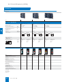
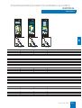
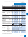
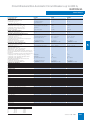
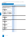
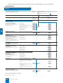
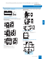
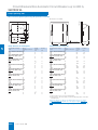
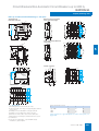
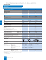
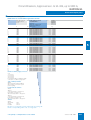
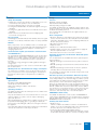
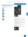
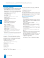
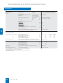
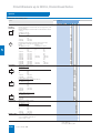
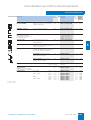
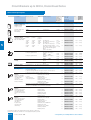
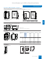
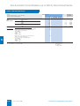
■ Overview
Size
I
II
III
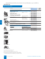
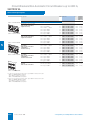
Circuit-breakers/non-automatic circuit-breakers
up to 6300 A, SENTRON WL
Rated current In
A
630, 800, 1000, 1250,
1600
3-pole, 4-pole
3-pole, 4-pole
3-pole, 4-pole
Rated operating voltage Ue
AC V
DC V
up to 690
up to 690/1000
up to 690/1000
Rated ultimate short-circuit
breaking capacity
at AC 415 V
kA
50/65
55/80/100
100
Endurance
Operat- 20000
ing cycles
15000
10000
Number of poles
3 0 ° 3 0 °
Service position
N S E 0 _ 0 0 0 6 1
Degree of protection
with cover
without cover
B
T
3 0 °
3 0 ° 3 0 °
3 0 °
N S E 0 _ 0 0 0 6 1
N S E 0 _ 0 0 0 6 2
IP55
IP20
Dimensions 3-/4-pole
H
3 0 °
3 0 ° 3 0 °
3 0 °
N S E 0 _ 0 0 0 6 1
N S E 0 _ 0 0 0 6 2
IP55
IP20
3 0 °
3 0 °
N S E 0 _ 0 0 0 6 2
IP55
IP20
W mm
Fixed-mounted
320/410
Withdrawable
320/410
Fixed-mounted
460/590
Withdrawable
460/590
Fixed-mounted
704/914
Withdrawable
704/914
H mm
434
465.5
434
465.5
434
466.5
D mm
291
471
291
471
291
471
NSS0_00535
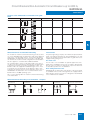
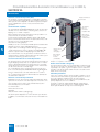
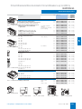
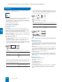
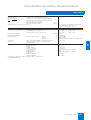
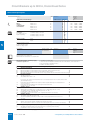
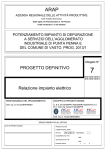
Electronic overcurrent trip units of SENTRON WL circuit-breakers
E T U 7 6 B
R a t in g P lu g
Q U E R Y
C L E A R
T E S T
Q U E R Y
R a t in g P lu g
R a t in g P lu g
C L E A R
=
1 2
R a t in g P lu g
N S E 0 _ 0 1 1 0 7
T E S T
- 6 7 # # *
- 6 7 " # *
% *
G F M
A T 4 5 B
g
A L A R M
T E S T
Q U E R Y
C L E A R
O F F :
G F M
T E S T
Q U E R Y
c s
c w
A T 5 5 B -7 6 B
C L E A R
R a t in g P lu g
G F M
T E S T
Q U E R Y
A T 5 5 B -7 6 B
C L E A R
N S E 0 _ 0 1 1 1 1
- 6 7
N S E 0 _ 0 1 1 1 0
# *
N S E 0 _ 0 1 1 0 9
- 6 7
N S E 0 _ 0 1 1 0 8
- 6 7 # *
N S E 0 _ 0 1 1 0 6
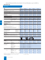
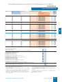
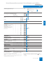
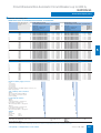
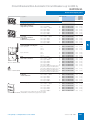
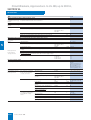
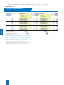
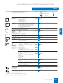
5
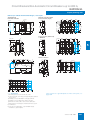
800, 1000, 1250, 1600, 2000, 2500, 4000, 5000, 6300
3200
Type
ETU15B
ETU25B
ETU27B
ETU45B
ETU55B
ETU76B
Overload protection
✓
✓
✓
✓
✓
✓
Short-time delayed short-circuit
protection
–
✓
✓
✓
✓
✓
Instantaneous short-circuit
protection
✓
✓
✓
✓
✓
✓
Neutral conductor protection
–
–
✓
✓
✓
✓
Ground-fault protection
–
–
✓
❑
❑
❑
Zone Selective Interlocking
–
–
–
❑
❑
❑
LCD, 4-line
–
–
–
❑
–
–
LCD, graphic
–
–
–
–
–
✓
Communication via
PROFIBUS DP
–
–
–
❑
❑
❑
Measurement functions
–
–
–
❑
❑
❑
Selectable parameter sets
–
–
–
–
✓
✓
Parameters freely programmable
–
–
–
–
✓
✓
✓ Standard
- Not available
❑ Optional
5/2
Siemens LV 30 · 2004
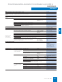
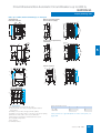
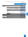
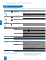
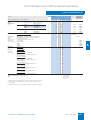
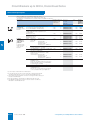
Air Circuit-Breakers (ACBs)
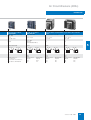
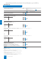
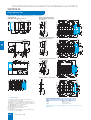
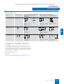
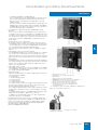
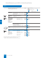
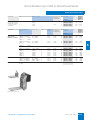
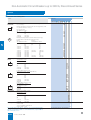
Introduction
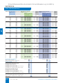
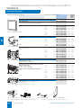
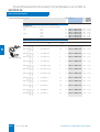
I, II, III
II
I
II
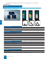
Circuit-breakers, approved acc. Non-automatic circuit-breakers Circuit-breakers, up to 3200 A, discontinued series
to UL 489, up to 5000 A,
for DC, up to 4000 A,
Non-automatic circuit-breakers, up to 3200 A, discontinued
SENTRON WL
SENTRON WL
series
1000, 1600, 2000, 2500, 3000,
4000, 5000
1000, 2000, 4000
630, 800, 1000, 1250, 1600
2000, 2500, 3200
3-pole
3-pole, 4-pole
3-pole, 4-pole
3-pole, 4-pole
up to 690
up to 690
up to 600 */347
up to 1000
65/100
30/25/20
(at DC 300/600/1000 V)
65
80
20000/15000/10000
15000
20000
20000
3 0 ° 3 0 °
N S E 0 _ 0 0 0 6 1
3 0 °
3 0 °
N S E 0 _ 0 0 0 6 2
3 0 ° 3 0 °
N S E 0 _ 0 0 0 6 1
3 0 °
3 0 °
N S E 0 _ 0 0 0 6 2
IP55
IP20
For dimensions see
circuit-breakers/
non-automatic circuit-breakers
up to 6300 A, SENTRON WL
3 0 ° 3 0 °
N S E 0 _ 0 0 0 6 1
3 0 °
3 0 °
N S E 0 _ 0 0 0 6 2
IP54
IP20
Fixed-mounted
460/590
Withdrawable
460/590
434
465,5
291
471
Fixed-mounted
300/390
3 0 ° 3 0 °
N S E 0 _ 0 0 0 6 1
5
3 0 °
3 0 °
N S E 0 _ 0 0 0 6 2
IP54
IP20
Withdrawable
280/370
Fixed-mounted
400/520
Withdrawable
380/500
470
485
470
485
330
445
330
445
Siemens LV 30 · 2004
5/3
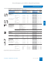
Circuit-Breakers/Non-Automatic Circuit-Breakers up to 6300 A,
SENTRON WL
General data
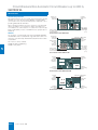
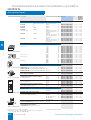
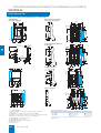
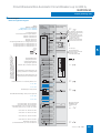
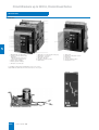
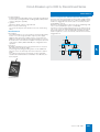
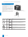
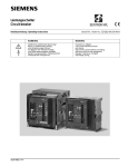
■ Overview
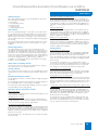
SENTRON WL:
Superior individual products integrated into uniform power distribution systems – up to and including industry-specific industrial and infrastructure solutions
*
%
&
+
)
(
,
-
$
5
9
:
=
7
.
/
6
;
0
<
8
1
5
3
4
2
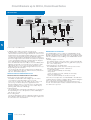
$ Guide frame
2 EMERGENCY-STOP pushbutton, key operated
% Main connection, front, flange, horizontal, vertical
3 Motorized operating mechanism
& Position indicator switch
4 Operating cycles counter
( Grounding contact, leading
5 Breaker status sensor (BSS)
) Shutter
6 Electronic overcurrent trip unit (ETU)
* COM15 PROFIBUS module
7 Reset solenoid
+ External CubicleBUS modules
8 Breaker data adapter (BDA)
, Closing solenoid, auxiliary release
9 4-line LCD module
- Auxiliary conductor plug-in system
: Ground-fault protection module
. Auxiliary switch block
; Rating plug
/ Door sealing frame
< Measuring function module
0 Interlocking set for baseplate
= Circuit-breaker
1 Transparent panel, function insert
5/4
Siemens LV 30 · 2004
Circuit-Breakers/Non-Automatic Circuit-Breakers up to 6300 A,
SENTRON WL
General data
■ Benefits
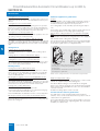
Low space requirements
The SENTRON WL devices require very little space. Size I
devices (up to 1600 A) fit into a 400 mm wide switchgear panel.
Size III devices (up to 6300 A) are the smallest of their kind and
with their construction width of 704 mm fit into a 800 mm wide
switchgear panel.
Modular design
Components like auxiliary releases, motorized operating mechanisms, overcurrent trip units, current sensors, auxiliary circuit
signaling switches, automatic reset devices and interlocks can
all be exchanged or retrofitted at a later stage, thus allowing the
circuit-breaker to be adapted to new, changing requirements.
■ Design
• Rated currents: 630 A to 6300 A
• 3 sizes for different rated current ranges (see illustration "Overview of SENTRON WL circuit-breakers/non-automatic circuitbreakers")
• 3 and 4-pole versions
• Rated operational voltage up to AC 690 V and 1000 V. Special
versions up to AC 1000 V available
• 3 different switching capacity classes in the range from 50 kA
to 100 kA for AC applications and one switching capacity class
for DC applications.
The main contact elements can all be replaced in order to increase the endurance of the circuit-breaker.
The SENTRON WL circuit-breakers are supplied complete with
operating mechanism (manual operating mechanism with mechanical closing), electronic overcurrent trip unit and auxiliary
switches (2 NO contacts + 2 NC contacts in the standard version), and can be equipped with auxiliary releases.
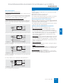
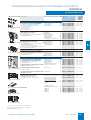
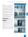
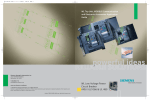
Retrofittable modules for electronic overcurrent trip units
Installation types
Modularity is one of the main features of the new SENTRON WL
circuit-breakers.
Special LCDs, ground-fault modules, rated current modules,
and communication modules for the electronic overcurrent trip
units are available for retrofitting.
Fixed-mounted or withdrawable version
Rating plugs
It is no longer necessary to replace the transformers in order to
change the rated current. The rating plugs, which have been integrated into the electronic overcurrent trip units and are easily
accessible, are exchanged instead. In this way, the circuitbreaker is quickly set to the new rated current and is also
marked accordingly.
Communication
Ambient temperatures
The SENTRON WL circuit-breakers are climate-proof in accordance with DIN IEC 68 Part 30-2. They are intended for use in
enclosed areas where no severe operating conditions (e.g. dust,
corrosive vapors, damaging gases) are present.
When installed in dusty and damp areas, suitable enclosures
must be provided.
Coordinated dimensions
The dimensions of SENTRON WL circuit-breakers of the same installation type only differ in terms of the width of the device which
depends on the number of poles and the frame size.
The use of modern communication-capable circuit-breakers
opens up completely new possibilities in terms of start-up, calibration, diagnosis, testing, maintenance, and power management.
Due to the nature of the design, the dimensions of devices with
a withdrawable design are determined by the dimensions of the
guide frames, which are slightly larger.
This allows many different ways of reducing costs and improving
productivity in industrial plants, buildings and infrastructure
projects to be achieved.
Non-automatic circuit-breakers
■ Area of application
• As incoming-feeder, distribution, tie, and outgoing-feeder circuit-breakers in electrical installations.
• For switching and protecting motors, capacitors, generators,
transformers, busbars and cables.
• Application as an EMERGENCY-STOP switch in conjunction
with an EMERGENCY-STOP device (DIN VDE 0113,
IEC 60 204-1).
Due to the reinforced use of electronic control systems, the demands made on air circuit-breakers in terms of operator control
and monitoring of network processes have increased.
The extensive, coordinated SENTRON range of devices covers
all applications between 16 A and 6300 A with compact and air
circuit-breakers.
The AC devices are available as circuit-breakers and non-automatic circuit-breakers. DC devices are only available as non-automatic circuit-breakers.
One special type of circuit-breaker is utilized as a non-automatic
circuit-breaker. The non-automatic circuit-breakers are designed without an electronic overcurrent trip unit system and do
not perform any protection duties for the system.
One potential application is the use as a bus coupler in systems
with parallel feed-ins.
The designs and specifications can be selected according to
those of the circuit-breakers.
Operating mechanisms
The switches are available with various optional operating
mechanisms:
• Manual operating mechanism with mechanical closing
(standard design)
• Manual operating mechanism with mechanical and electrical
closing
• Motorized operating mechanism with mechanical and electrical closing.
The operating mechanisms with electrical closing can be used
for synchronization tasks.
Specifications
SENTRON WL circuit-breakers satisfy:
• IEC 60947-2
• DIN VDE 0660 Part 101
• climate-proof to DIN IEC 68 Part 30-2.
Also available with UL 489.
For further specifications, see Annex.
Siemens LV 30 · 2004
5/5
5
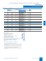
Circuit-Breakers/Non-Automatic Circuit-Breakers up to 6300 A,
SENTRON WL
General data
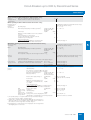
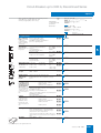
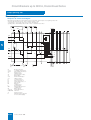
C ir c u it- b r e a k e r
m a x . ra te d c u rre n t
n m a x
B r e a k in g c a p a c ity
(A )
c u
c c
D im e n s io n s
a t 4 4 0 V A C (k A ) o r
a t 3 0 0 V D C (k A )
F ix e d - m o u n te d ,
3 - /4 - p o le
S iz e III
6 3 0 0
5 0 0 0
H
1 0 0
4 0 0 0
3 2 0 0
2 5 0 0
D ra w -o u t
3 - /4 - p o le
7 0 4 / 9 1 4
7 0 4 / 9 1 4
W id th
4 3 4 / 4 3 4
4 6 0 / 4 6 0
H e ig h t
2 9 1 / 2 9 1
3 8 5 / 3 8 5
D e p th
4 6 0 / 5 9 0
4 6 0 / 5 9 0
W id th
4 3 4 / 4 3 4
4 6 0 / 4 6 0
H e ig h t
2 9 1 / 2 9 1
3 8 5 / 3 8 5
D e p th
3 2 0 / 4 1 0
3 2 0 / 4 1 0
W id th
4 3 4 / 4 3 4
4 6 0 / 4 6 0
H e ig h t
2 9 1 / 2 9 1
3 8 5 / 3 8 5
D e p th
S iz e II
2 0 0 0
1 6 0 0
1 2 5 0
5
1 0 0 0
D C
N
3 0
5 5
1 )
S
H
8 0
1 0 0
8 0 0
1 6 0 0
S iz e I
1 2 5 0
1 0 0 0
N
S
8 0 0
5 0
6 5
6 3 0
N S E 0 _ 0 0 8 8 7 i
T h e d im e n s io n fo r th e d e p th o f th e c ir c u it- b r e a k e r is fr o m th e c ir c u it- b r e a k e r r e a r to th e in n e r s u r fa c e o f th e c lo s e d s w itc h g e a r d o o r .
1 ) S iz e II, c u = 5 5 k A ; d e liv e r a b le fo r n m a x = 2 0 0 0 A a n d 2 5 0 0 A
Overview of SENTRON WL circuit-breakers/non-automatic circuit-breakers
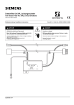
The type of connection for the auxiliary switches depends on the
type of installation:
• Withdrawable version
The internal auxiliary switches are connected to the male connector on the switch side. When the breaker is fully inserted,
the blades make a connection with the slide module in the
guide frame. Various adapters can then be used to complete
the wiring (see illustration "Connection options for auxiliary
circuit connections").
• Fixed-mounted version
In this case the auxiliary circuit plugs are engaged directly onto
the circuit-breaker. The connectors are equipped with coding
pins that prevent them being mistakenly interchanged.
5/6
Siemens LV 30 · 2004
N S E 0 _ 0 0 9 7 9
N S E 0 _ 0 0 9 6 9 a
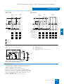
Front connection with single
hole or double hole
Vertical
connection
N S E 0 _ 0 0 9 7 3 a
N S E 0 _ 0 0 9 7 2 a
N S E 0 _ 0 0 9 6 7 a
Horizontal
connection
Vertical
connection
N S E 0 _ 0 0 9 7 1 a
Front connection with single
hole or double hole
Flange
connection
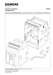
Main current connections – connection types
Connection using
screw connection
system (SIGUT)
(standard)
N S E 0 _ 0 0 9 7 6 a
Auxiliary circuit connections
Horizontal
connection
N S E 0 _ 0 0 9 7 0 a
The following options are available:
• Accessible from the front, one hole (for vertically installed
busbars)
• Accessible from the front, two holes (holes in accordance with
DIN 43673) (for vertically installed busbars)
• At the rear, vertical (for vertically installed busbars)
• Connecting flange (for direct connection to guide frame up to
4000 A).
N S E 0 _ 0 0 9 6 7 a
Circuit-breakers with a max. rated current of 6300 A are
equipped with vertical main circuit connections (for vertically
installed busbars).
N S E 0 _ 0 0 9 7 5 a
All circuit-breakers are equipped with horizontal main circuit
connections on the rear for up to 5000 A as standard (horizontal
connection to busbars).
N S E 0 _ 0 0 9 6 8 a
Main circuit connections
Screwless
connection system
(tension spring)
(option)
Connection options for auxiliary circuit connections
Circuit-Breakers/Non-Automatic Circuit-Breakers up to 6300 A,
SENTRON WL
General data
Operator panel
The operator panel is designed to protrude from a cutout in the
door providing access to all operator controls and displays with
the door closed.
The operator panels for all circuit-breakers (fixed-mounted/withdrawable designs, 3-/4-pole) are identical. The operator panel
ensures degree of protection IP20.
Safety and reliability
To protect the circuit-breakers and plant against unauthorized
switching as well as the maintenance and operator personnel,
the system contains many blocking devices. Others can be retrofitted.
Other safety features include:
• Incoming supply from above or below, as required
• Locking of the guide frame with the circuit-breaker removed, as
standard
• Locking of the withdrawable circuit-breaker against movement,
as standard
• High degree of protection with cover IP55
• Mechanical closing lockout after overload or short-circuit tripping as standard
• The circuit-breaker is always equipped with the required number of auxiliary supply connectors
• Devices with electronic overcurrent trip units from ETU45B and
higher are always equipped with temperature sensors on BSS
and COM15 module.
Standard version
SENTRON WL circuit-breakers are equipped with the following
features as standard:
• Mechanical ON and OFF pushbutton
• Manual drive with mechanical request
• Switch position indication
• Ready-to-close indicator
• Memory status indicator
• Auxiliary switches (2 NO + 2 NC)
• Rear horizontal main circuit connections for fixed mounted and
withdrawable versions up to 5000 A, and rear vertical main circuit connections for 6300 A applications
• For 4-pole circuit-breakers, the fourth pole (N) is installed on
the left and is 100% loadable
• Contact erosion indicator for the main contacts
• Auxiliary circuit plug system with SIGUT screw-type terminals.
Delivery inclusive of all auxiliary circuit connectors to internal
specifications including coding device for the prevention of incorrect installation of fixed-mounted circuit-breakers
• Mechanical "tripped" indicator for electronic overcurrent trip
unit system
• Mechanical closing lockout after tripping operation
• Control panel cannot be taken off with the switch in the ON
position
• User manual on CD-ROM (for printed version see options)
• The withdrawable circuit-breaker cannot be moved when it is
in the ON position
• Coding of the rated current between the guide frame and the
withdrawable circuit-breaker.
Withdrawable short-circuit, ground, and bridging units
Portable positively-driven ground and short-circuit devices are
used for the disconnected system sections to verify isolation
from the supply at the workplace.
Withdrawable grounding units allow simple and comfortable
grounding. They are simply inserted into the guide frames in
place of the corresponding withdrawable circuit-breakers. This
ensures that these devices are always first connected with the
ground electrode and then with the components to be grounded.
The ground terminals are fitted to the side of the switch enclosure and establish the connection when inserted into the guide
frame.
Short-time current of the ground
terminal
15 kA (500 ms)
Rated operational voltage
1000 V
Specification
DIN VDE 0683
5
All withdrawable terminals are short-circuited and grounded on
delivery.
Qualified electricians can easily convert it to a withdrawable
bridging unit by following the enclosed instructions.
In addition, the withdrawable unit can be adapted to each rated
current of a frame size.
Withdrawable short-circuit and grounding unit
The withdrawable short-circuit and grounding unit consists of a
breaker enclosure with penetration blades which are connected
with the short-circuiting link.
Depending on the version, the short-circuiting links are arranged
at the top or bottom. The ground and short-circuit connections
are established when the device is inserted.
It must be ensured that the side to be short-circuited and
grounded is not live. For this reason it is recommended that the
withdrawable unit is only wound in when the door is closed.
Withdrawable bridging unit
The withdrawable bridging unit consists of a breaker enclosure
in which all disconnection components and the operating mechanism have been replaced with simple connections between the
upper and lower contacts.
Additional features of the withdrawable design:
• Main contacts:
Laminated receptacles in the guide frame, penetration blades
on the withdrawable circuit-breaker
• Position indicator in the control panel of the withdrawable
circuit-breaker
• Captive manual crank lever for moving the withdrawable
circuit-breaker
• Guide frame with guide rails for easy moving of the withdrawable circuit-breaker
• The withdrawable circuit-breaker can be locked to prevent it
being pushed out of position
Siemens LV 30 · 2004
5/7
Circuit-Breakers/Non-Automatic Circuit-Breakers up to 6300 A,
SENTRON WL
General data
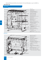
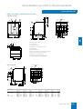
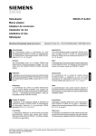
Circuit-breaker
(1 )
(2 8 )
(2 )
(2 7 )
(3 )
(2 6 )
(4 )
(2 5 )
(5 )
% Carrying handle
& Labeling plates
( Motor cutout switch (option) or
"Electrical ON" (option)
) Name plate for circuit-breaker
* Spring charge indicator
+ "Mechanical ON" button
, Rated current indication
- Positioning pictogram
. Operating cycles counter (option)
(2 4 )
(6 )
(2 3 )
/ Hand-operated lever
0 Crank handle
(7 )
(2 2 )
(2 1 )
5
$ Arc chute
1 Withdrawable unit drive shaft
2 Equipment plate
3 Grounding connection
(8 )
4 Position indicator
(2 0 )
(9 )
6 Safety lock for crank handle (option)
(1 9 )
(1 0 )
(1 1 )
(1 8 )
(1 7 )
(1 6 )
5 Table for ground-fault protection
7 Mechanical unlocking of
crank handle (option)
8 Electronic overcurrent trip unit
9 Rating plug
(1 2 )
: "Mechanical OFF" button or
"EMERGENCY-STOP" mushroom pushbutton (option)
(1 3 )
; Ready-to-close indicator
(1 4 )
(1 5 )
< Switch position indication
N S E 0 _ 0 0 9 6 5 a
= "Tripped" indicator (reset button)
> “Secure OFF"
locking device (option)
? Operator panel
@ Male connector for auxiliary connections
Guide frame
$ Arc chute cover (option)
% Blow-out openings
(1 )
& Opening for crane hook
(2 )
( Shutter (option)
) Locking device (shutter) (option)
* Name plate for guide frame
(3 )
(1 8 )
+ Isolating contacts
, Ground terminal Ø 14 mm
- Locking device for racking rail
(4 )
(1 7 )
(5 )
(1 6 )
(6 )
(7 )
(1 5 )
/ Door interlock for guide frame
(option)
0 Racking rail
1 Factory-set rated current coding
2 Sliding contact for breaker grounding
(option)
3 Equipment-dependent coding (option)
4 Shutter actuator (option)
5 Position indication switch (option)
(1 4 )
(8 )
(1 3 )
(1 2 )
(9 )
(1 1 )
(1 0 )
5/8
. Locking device against movement when
cabinet door is open (option)
N S E 0 _ 0 0 9 6 6 a
Siemens LV 30 · 2004
6 Sliding contact module for auxiliary conductors (number depends on equipment)
Circuit-Breakers/Non-Automatic Circuit-Breakers up to 6300 A,
SENTRON WL
General data
Auxiliary releases
Automatic resetting of closing lockout
Up to two auxiliary releases can be installed at the same time.
The following are available:
When the ETU is activated, reclosing of the circuit-breaker is
prevented until the trip unit is either electrically or manually reset.
If the "Automatic resetting of closing lockout" option is used, the
circuit-breaker is ready to close immediately after tripping. Resetting the manual "tripped" indicator is not included in this option.
1 shunt release
or 1 undervoltage release
or 2 shunt releases
or 1 shunt release
+ 1 undervoltage release.
Shunt release
When the operating voltage is connected to the shunt release,
the circuit-breaker is opened immediately. The shunt release is
available in the variants 5 % ON-time for overexcitation and
100 % ON-time for permanent excitation. This means that it is
also possible to block the circuit-breaker against being jogged
into closing.
An energy storage device for shunt releases allows the circuitbreaker to be opened even if the control voltage is no longer
available.
Undervoltage release
The undervoltage release causes the circuit-breaker to be
opened if the operating voltage falls below a certain value or is
not applied. The circuit-breaker cannot be opened manually or
by means of an electrical ON command if the undervoltage release is not connected to the rated voltage. The undervoltage release has no delay as standard. A delay can be set by the customer in the range between td < 80 ms and td < 200 ms.
In addition, an undervoltage release with a delay in the range
from 0.2 to 3.2 s is available.
Alarm switch for auxiliary releases
One signal contact is used for each auxiliary release to determine the positions of the auxiliary releases.
Tripped signal switch
If the circuit-breaker has tripped due to an overload, short-circuit, ground fault or extended protection function, the tripped
signal switch can indicate this. This signal switch is available as
an option. If the circuit-breaker is used for communication, this
option is supplied as standard.
Ready-to-close signal switch
The SENTRON WL circuit-breakers are equipped with an optical
ready-to-close indicator as standard. In addition, the ready-toclose status can be transmitted by means of a signal switch as
an option. If the switch is used for communication, the signal
switch is supplied as standard.
5
Locking devices
Locking device in OFF position
This function prevents closing of the circuit-breaker and fulfills
the specifications for main switches to EN 60204 (VDE 0113) –
disconnector unit. This lockout only affects this switch.
If the circuit-breaker is replaced, closing is no longer prevented
unless the new circuit-breaker is also protected against unauthorized closing.
To activate the locking device, the circuit-breaker must be
opened. The locking device is disabled when the circuit-breaker
is closed. The lock is only activated when the key is removed.
The safety key can only be removed in the OFF position.
Closing solenoid
Locking device for "electrical ON"
The closing solenoid is used to close the circuit-breaker electrically by means of a local electrical ON command or by a remote
unit.
This prevents unauthorized electrical closing from the operator
panel. Mechanical closing and remote closing remain possible.
The lock is only activated when the key is removed.
Motorized operating mechanism
Locking device for "mechanical ON"
The operating mechanism is used to load the storage spring automatically.
The operating mechanism is activated if the storage spring has
been unloaded and the control voltage is available.
This prevents unauthorized mechanical closing. The mechanical
ON button can only be activated if the key is inserted (key operation). Closing with the "electrical ON" button and remote closing
remain possible. The lock is only activated when the key is removed.
It is switched off automatically after loading. This does not affect
manual loading of the storage spring.
"Secure OFF", switch-independent locking device against unauthorized closing
Indicators, signals, and operator controls
This special switch-independent function for withdrawable circuit-breakers prevents closing and fulfills the specifications for
main switches to EN 60204 (VDE 0113) – disconnector unit. Unauthorized closing remains impossible even after the circuitbreaker has been exchanged.
Motor STOP switch
Control switch for switching off the motorized operating mechanism (automatic loading).
Operating cycles counter
The motorized operating mechanism can be supplied with a
5-digit operating cycles counter. The display is incremented by
"1" as soon as the storage spring is fully loaded.
To activate the lock, the circuit-breaker must be opened. The
locking device is disabled when the circuit-breaker is closed.
The lock is only activated when the key is removed. The safety
key can only be removed in the OFF position.
Resetting the manual "tripped" signal
When the circuit-breaker has tripped, this is indicated by the red
protruding reset button on the ETU. When the reset button is activated, the tripping solenoid and tripped signal are reset. If this
display is to be reset remotely, the reset button can be equipped
with a reset solenoid.
This option allows the circuit-breaker to be reset both manually
and electrically.
Siemens LV 30 · 2004
5/9
Circuit-Breakers/Non-Automatic Circuit-Breakers up to 6300 A,
SENTRON WL
General data
Locking device for manual crank
Additional equipment for guide frames
Prevents removal of the crank. The circuit-breaker is protected
against movement. The lock is only activated when the key is removed.
Shutters
Locking device for "mechanical OFF"
Prevents unauthorized mechanical opening from the operator
panel. The mechanical OFF button can only be activated if the
key is inserted (key operation). Remote opening remains possible. The lock is only activated when the key is removed.
Locking device for hand-operated lever
The hand-operated lever can be locked with a padlock. The storage spring cannot be loaded manually.
Locking device against resetting the "tripped" indicator
A lockable cover prevents manual resetting of the "tripped" indicator after overcurrent tripping. This locking device is supplied
together with the transparent cover for electronic overcurrent trip
units.
The sealing strips can be manually opened using the strip levers.
The position of the sealing strips can be locked in various positions using padlocks for securing against tampering.
Rated current coding unit between circuit-breaker and guide
frame
Withdrawable circuit-breakers and guide frames are equipped
with a rated current coding unit as standard.
This ensures that only circuit-breakers whose penetration blades
are suited to the laminated contacts of the guide frame can be
inserted into a guide frame (see diagram below).
Sealing devices
Sealing cap for "electrical ON" button
The "electrical ON" button is equipped with a sealing cap as
standard.
(1)
Sealing cap for "mechanical ON and OFF" buttons
(4)
The locking set contains covering caps which can be sealed.
Sealing device for electronic overcurrent trip units
The transparent cover can be sealed. The configuration sections
are covered to prevent unauthorized access. Openings allow
access to the query and test button.
Blocking devices
Closing lockout when cabinet door is open
Ready-to-close is deactivated mechanically when the cabinet
door is open. The circuit-breaker can neither be mechanically
nor electrically closed. The blocking signal is transmitted by
means of a Bowden wire.
Blocking device against movement for withdrawable circuitbreakers when the cabinet door is open.
The manual crank is blocked when the cabinet door is open and
cannot be removed. The withdrawable circuit-breaker cannot be
moved. The lock only affects the inserted manual crank.
Locking of the control cabinet door
The control cabinet door cannot be opened if
• the fixed-mounted circuit-breaker is closed (the blocking signal is transmitted via the Bowden wire) or
• if the withdrawable circuit-breaker is in the connected position.
Blocking mechanism via "mechanical ON and OFF" buttons
The "mechanical ON" and "OFF" buttons are covered with a cap
which only allows activation with a tool. These covering caps are
part of the locking set.
5/10
Siemens LV 30 · 2004
NSE01031
5
The sealing strips of the shutter seal the laminated contacts of
the guide frame when the withdrawable circuit-breaker is removed and therefore implement shock protection.
(2)
(3)
NSE01032
(5)
(1) Guide frame, interior of l/h side; interior of r/h side similar
(2) Coding pin on racking rail in guide frame
(3) Racking rail
(4) Withdrawable circuit-breaker, r/h side; l/h side similar
(5) Coding pin on guide frame
Rated current coding unit between circuit-breaker and guide frame
Equipment-dependent coding
Withdrawable circuit-breakers and guide frames can be retrofitted with an equipment-dependent coding unit.
This allows different designs of circuit-breakers and guide
frames to be uniquely assigned. If the circuit-breaker and guide
frame have been assigned different codes, the circuit-breaker
cannot be inserted.
36 different coding options can be selected.
Position indicator switch for guide frames
The guide frame can be retrofitted with position indicator
switches. These can be used to determine the position of the circuit-breaker in the guide frame.
The position indicator switches have factory-fitted 1.5 m long cables and are mounted on the supporting plate. Two versions are
available (see table below).
Circuit-Breakers/Non-Automatic Circuit-Breakers up to 6300 A,
SENTRON WL
General data
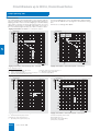
Positions of the withdrawable circuit-breaker in the guide
frame
Display
Position indicator
Maintenance position
(2)
(1)
CONNECT
Main circuit
Auxiliary circuit
Control cabinet door Shutter
disconnected
disconnected
open
closed
disconnected
disconnected
closed
closed
disconnected
connected
closed
closed
connected
connected
closed
open
TEST
(4)
DISCON
NSE01033
NSE01037
Disconnected position
CONNECT
(3)
TEST
DISCON
NSE01034
NSE01038
Test position
CONNECT
TEST
DISCON
NSE01035
NSE01039
Connected position
CONNECT
5
TEST
DISCON
NSE01036
(1) Auxiliary circuit
NSE01040
(2) Main circuit
(3) Control cabinet door
(4) Shutter
Mutual mechanical circuit-breaker interlocking
Phase barriers
The module for mutual mechanical interlocking can be used for
one or two SENTRON WL circuit-breakers and can be adapted
easily to the corresponding versions. The fixed-mounted and
withdrawable circuit-breaker versions are fully compatible and
can therefore be used in a mixed configuration in an installation.
This also applies to circuit-breakers 3WN6 and 3WN1.
The plant engineering company can manufacture phase barriers
made of insulating material for the arcing fault barriers. The rear
panel of the fixed-mounted circuit-breakers or guide frames are
equipped with guide grooves.
The circuit-breakers can be mounted alongside each other or
one above the other, whereby the spacing of the circuit-breakers
is determined solely by the length of the Bowden cable. The
Bowden cables are supplied in standard lengths of 2 m. Interlock signals are looped through via the Bowden cables. Interlocking is only effective in the connected position in the case of
withdrawable circuit-breakers. The mechanical lifetime of the
Bowden wires is 10,000 operating cycles.
The arc chute cover is available as optional equipment for the
guide frame (standard for versions in accordance with UL 489).
The arc chute cover protects switchgear components which are
located directly above the circuit-breaker.
Arc chute cover
Door sealing frame and cover
SENTRON WL circuit-breakers have degree of protection IP20
as standard. However, if the switchgear is to be equipped with a
higher degree of protection, a door sealing frame with IP40 and
a cover with IP55 are available.
Also see the following table for mutual mechanical interlocking
of circuit-breakers.
Mutual mechanical interlocking of circuit-breakers – examples
Mutual interlocking of two
circuit-breakers
Interlocking between three
circuit-breakers
Mutual interlocking of three
circuit-breakers
G
S1
S2
S1
S2
NSE01041
NSE01042
G
G
S3
S1
S1
NSE01043
S2
S2
Interlocking of three circuitbreakers, two of them mutual
S3
S1
S3
S2
S3
NSE01044
NSE01045
Siemens LV 30 · 2004
5/11
Circuit-Breakers/Non-Automatic Circuit-Breakers up to 6300 A,
SENTRON WL
General data
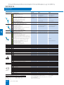
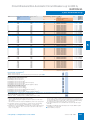
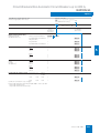
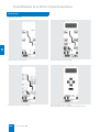
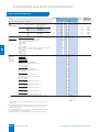
■ Functions
Functions of the electronic overcurrent trip units
ETU15B
ETU27B
ETU25B
NSE00881a
NSE00880a
TEST
CLEAR
QUERY
R
TEST
CLEAR
QUERY
R
R
5
s d
s d
t
t
s d
t
i
ETU15B
g
ETU25B
ETU27B
Basic protection functions
Overload protection
L
✔
✔
✔
Short-time delayed short-circuit protection
S
–
✔
✔
Instantaneous short-circuit protection
I
✔
✔
✔
Neutral conductor protection
N
–
–
✔
Ground-fault protection
G
–
–
✔
N-conductor protection can be switched on/off
–
–
✔
Short-time delayed short-circuit protection can be switched on/off
–
–
–
Non-delayed short-circuit protection can be switched on/off
–
–
–
Thermal image can be switched on/off
–
–
–
Additional functions
Load monitoring
–
–
–
Short-time delayed short-circuit protection can be switched
to I2t
–
–
–
Non-delayed short-circuit protection adjustable
✔
–
–
Overload protection switchable to I4t
–
–
–
Overload protection can be switched on/off
–
–
–
N-conductor protection adjustable
–
–
–
Selectable parameter sets
–
–
–
Configuration via rotary coding switches (10 steps)
✔
✔
✔
Configuration via communication (absolute values)
–
–
–
Configuration via user interface of ETU (absolute values)
–
–
–
Configuration of expanded protection functions
–
–
–
LCD alphanumerical
–
–
–
Graphic LCD
–
–
–
Measurement function
–
–
–
Measurement function Plus
–
–
–
CubicleBUS
–
–
–
Communication via PROFIBUS DP
–
–
–
Communication via Ethernet
–
–
–
Configuration and displays
Measurement function
Communication
✔ Standard
– Not available
❑ Optional
Detailed information about the functions of the electronic overcurrent trip units is given in the following.
5/12
Siemens LV 30 · 2004
s d
g
N S E 0 _ 0 0 9 5 2 b
N S E 0 _ 0 0 9 5 1 b
N S E 0 _ 0 0 9 5 0 b
NSE00882a
Rating Plug
Rating Plug
Circuit-Breakers/Non-Automatic Circuit-Breakers up to 6300 A,
SENTRON WL
General data
ETU76B
ETU55B
ETU45B
Rating Plug
Rating Plug
=
12
Rating Plug
OFF :
cs
cw
GFM AT 55B-76B
GFM AT 45B
GFM AT 55B-76B
g
TEST
CLEAR
QUERY
TEST
QUERY
IR
IR
IR
tR
tR
tR
Ig
tg
Isd
t sd
Ii
NSE0 00953a
Ig
tg
Isd
t sd
Ii
NSE0 00953a
Ig
tg
NSE00886a
CLEAR
QUERY
NSE00884a
TEST
NSE00883a
ALARM
CLEAR
5
Isd
t sd
Ii
NSE0 00953a
ETU45B
ETU55B
ETU76B
✔
✔
✔
✔
✔
✔
✔
✔
✔
✔
✔
✔
❑
❑
❑
✔
✔
✔
✔
✔
✔
✔
✔
✔
✔
✔
✔
✔
✔
✔
✔
✔
✔
✔
✔
✔
✔
✔
✔
–
✔
✔
✔
✔
✔
–
✔
✔
✔
–
–
–
✔
✔
–
–
✔
❑
❑
❑
❑
–
–
–
–
✔
❑
❑
❑
❑
❑
❑
✔
✔
✔
❑
❑
❑
❑
❑
❑
Siemens LV 30 · 2004
5/13
Circuit-Breakers/Non-Automatic Circuit-Breakers up to 6300 A,
SENTRON WL
General data
Electronic overcurrent trip units (ETU)
"Tripped" indication/
reset button
The electronic overcurrent trip unit is controlled by a microprocessor and operates independently of an auxiliary voltage. It enables systems to be adapted to the different protection requirements of distribution systems, motors, transformers and
generators.
Communication capability
Text display
with 15°
inclination,
rotatable 180°
The international standard PROFIBUS DP can be used to transmit data such as current values, switching states, reasons for
tripping etc. to central computers.
Microswitch
for switchable
overload
characteristic
Data acquisition and energy management are possible in conjunction with the measurement function.
5
A new internal circuit-breaker data bus allows switchboard
panel communication between the circuit-breaker and secondary devices in the circuit-breaker panel:
• Actuation of analog displays
• Ability to test the communication build-up with circuit-breakers
• Display of release status and tripping reasons
• Input module for reading in further switchgear panel signals
and for transmission of these signals to the PROFIBUS DP
• Various output modules for displaying measured values.
This means that it is not only possible to monitor the device remotely, but also to transmit current values from the entire system
and perform switching operations remotely.
I2t and I4t characteristic for overload protection
The best protection for the whole switchgear is achieved by setting the tripping characteristic to an optimum value. In order to
achieve optimal discrimination for upstream fuses or medium
voltage protection systems, the inclination of the characteristic
can be selected for the overload range.
The overload protection L (long time protection) for the electronic overcurrent trip units ETU45B, ETU55B, and ETU76B allows the characteristic to be switched between I2t and I4t.
The I4t characteristic improves discrimination for downstream
circuit-breakers and fuses.
Electronic overcurrent trip units ETU
Modularity has also been strictly emphasized during the development of the electronic overcurrent trip units. These are some
of the modules which can be easily retrofitted at any time:
• Ground-fault protection modules
• Communication
• Measurement function
• Displays
• Rated current modules (rating plugs)
This allows quick adaptation to new local mains specifications.
In addition, new innovative functions have been included in the
ETUs.
5/14
Siemens LV 30 · 2004
Rated current
module /
rating plug
Ground-fault
protection
module
(retrofittable)
Example of configuration for ETU45B
Rated current module / rating plug
The rated current module is an exchangeable module which allows the user to reduce the rated device current so as to adapt
it optimally to the plant; e.g. if a new plant section is taken into
operation. The rated current module must be selected to fit the
rated current of the plant.
Selectable parameters
In the case of quick changes of power supply conditions, e.g. for
switchovers from transformer to generator operation or if a section of the supply is shutdown when the shift changes,
SENTRON WL allows the relevant protection parameters to be
quickly adapted to the new conditions.
The ETUs contain two independent tripping characteristics
(parameter sets). The switchover is completed within 200 ms
and is performed with the help of an external signal.
Circuit-Breakers/Non-Automatic Circuit-Breakers up to 6300 A,
SENTRON WL
General data
ETU15B electronic overcurrent trip unit
O p tio
p re v e
re s e t
o v e rc
M e c h a n ic a l R E S E T
fo r r e c lo s in g lo c k o u t
n : s a
n ts p
b u tto
u rre n
fe
re
n
t
ty
s
a
re
lo c k
s in g o f
fte r
le a s e
E T U 1 5 B
In d ic a to r : o v e r c u r r e n t
r e le a s e a c tiv a te d
In d ic a to r : fa u lt in
o v e r c u r r e n t r e le a s e
In d ic a to r : o v e r lo a d a la r m
R o ta r y s w itc h fo r s e ttin g
v a lu e , o v e r lo a d r e le a s e
R o ta r y s w itc h fo r s e ttin g
v a lu e , in s ta n ta n e o u s
s h o r t- c ir c u it r e le a s e
N S E 0 _ 0 0 9 5 4
S e a lin g r in g
Application:
Simple building and plant protection without time-selective grading
up to 3200 A
Features:
• Adjustable overload protection
with I2t characteristic with
preset delay time
tR = 10 seconds at 6 × IR
• Non-delayed short-circuit protection adjustable in the range
from 2 to 8 × In
• Overload display
• Protection function is set by
means of the rotary coding
switch
For technical details see table
"Function overview of the
electronic overcurrent trip unit system" under "Technical specifications".
T e s t s o c k e t
5
ETU25B electronic overcurrent trip unit
O p tio
p re v e
re s e t
o v e rc
M e c h a n ic a l R E S E T
fo r r e c lo s in g lo c k o u t
In d ic a to r : o v e r c u r r e n t
r e le a s e a c tiv a te d
n : s a
n ts p
b u tto
u rre n
fe
re
n
t
ty
s
a
re
lo c k
s in g o f
fte r
le a s e
E T U 2 5 B
In d ic a to r : o v e r lo a d a la r m
In d ic a to r : fa u lt in
o v e r c u r r e n t r e le a s e
R a tin g P lu g
R a te d c u r r e n t m o d u le
R o ta r y s w itc h fo r s e ttin g
v a lu e , o v e r lo a d r e le a s e
In d ic a to r : c a u s e o f r e le a s e
R o ta r y s w itc h fo r s e ttin g
v a lu e , in s ta n ta n e o u s
s h o r t- c ir c u it r e le a s e
R o ta r y s w itc h fo r d e la y ,
s h o r t- c ir c u it r e le a s e
S h o r t- c ir c u it p r o te c tio n
fix e d s e ttin g
N S E 0 _ 0 0 9 5 5
Q u e ry p u s h b u tto n
T e s t p u s h b u tto n
S e a lin g r in g
T E S T
Q U E R Y
C L E A R
C le a r p u s h b u tto n
T e s t s o c k e t
Application:
Classical building, motor and plant
protection with time-selective coordination for up to 6300 A
Features:
• Adjustable overload protection
with I2t characteristic
preset delay time
tR = 10 seconds at 6 × IR
• Short-time delayed short-circuit
protection adjustable in the
range from 1.25 to 12 × In and
• Non-delayed short-circuit protection preset to
20 × In/max. 50 kA
• Can be adapted to the required
plant currents through retrofittable rated current module to ensure overload protection in the
range from 100 A to 6300 A.
• Overload display
• Indicates the reason for tripping
by means of an LED
• Test option for the trip unit
• Protection functions are
set by means of the
rotary coding switch
For technical details see table
"Function overview of the electronic overcurrent trip unit system"
under "Technical specifications".
Siemens LV 30 · 2004
5/15
Circuit-Breakers/Non-Automatic Circuit-Breakers up to 6300 A,
SENTRON WL
General data
ETU27B electronic overcurrent trip unit
O p tio
p re v e
re s e t
o v e rc
fe
re
n
t
ty
s
a
re
Application:
lo c k
s in g o f
fte r
le a s e
Classical building, motor and plant
protection with time-selective
coordination for up to 6300 A
N S E 0 _ 0 0 9 5 6 a
M e c h a n ic a l R E S E T
fo r r e c lo s in g lo c k o u t
n : s a
n ts p
b u tto
u rre n
Features:
In d ic a to r : o v e r c u r r e n t
r e le a s e a c tiv a te d
E T U 2 7 B
In d ic a to r : o v e r lo a d a la r m
O F F O N
N - c o n d u c to r p r o te c tio n
o n /o ff
In d ic a to r : fa u lt in
o v e r c u r r e n t r e le a s e
R a tin g P lu g
R a te d c u r r e n t m o d u le
R o ta r y s w itc h fo r s e ttin g
v a lu e , o v e r lo a d r e le a s e
N
In d ic a to r : c a u s e o f r e le a s e
R o ta r y s w itc h fo r d e la y ,
s h o r t- c ir c u it r e le a s e
R o ta r y s w itc h fo r s e ttin g
v a lu e , in s ta n ta n e o u s
s h o r t- c ir c u it r e le a s e
S h o r t- c ir c u it p r o te c tio n
fix e d s e ttin g
For technical details see table
"Function overview of the electronic overcurrent trip unit system"
under "Technical specifications".
S e a lin g r in g
O F F
R o ta r y s w itc h fo r d e la y ,
e a r th - fa u lt p r o te c tio n
R o ta r y s w itc h fo r s e ttin g
v a lu e , e a r th - fa u lt p r o te c tio n
Q u e ry p u s h b u tto n
T e s t p u s h b u tto n
C le a r p u s h b u tto n
T E S T
C L E A R
Q U E R Y
T e s t s o c k e t
ETU45B electronic overcurrent trip unit
O p tio
p re v e
re s e t
o v e rc
M e c h a n ic a l R E S E T
fo r r e c lo s in g lo c k o u t
S c r o ll u p
O v e r lo a d a la r m
T h e rm
N -c o n
S e ttin
N -c o n
T ra n s
c h a ra
E T U 4 5 B
O F F
R a te d c u r r e n t m o d u le
R a tin g P lu g
R o ta r y s w itc h fo r s e ttin g
v a lu e , o v e r lo a d r e le a s e
1
1
1
1
1
R o ta r y s w itc h fo r s e ttin g
v a lu e , s h o r t- c ir c u it
p r o te c tio n
n
g
n
itc h fo r s e ttin g
r th - fa u lt a la r m
s t p u s h b u tto n
ry p u s h b u tto n
O N
=
R o ta r y s w itc h fo r s e ttin g
v a lu e , in s ta n ta n e o u s
s h o r t- c ir c u it r e le a s e
R o ta ry s w
v a lu e , e a
T e
Q u e
fe
re
n
t
ty
s
a
re
Application:
lo c k
s in g o f
fte r
le a s e
S c r o ll d o w n
In d ic a to r : fa u lt in
o v e r c u r r e n t r e le a s e
C O M M U N IC A T IO N
E X P A N D E D
S e le c to r fo
e a r th - fa u lt p r o te c tio
R o ta r y s w itc h fo r s e ttin
v a lu e , e a r th - fa u
p r o te c tio
n : s a
n ts p
b u tto
u rre n
O p tio n : a lp h a n u m e r ic d is p la y
In d ic a to r s :
O v e r c u r r e n t r e le a s e
a c tiv a te d
1 2
5
The same as ETU25B but also
including
• Reversible neutral conductor
protection
• Permanently integrated groundfault protection. Calculation of
the ground-fault current through
vectorial summation current formation
I i= O F F : IC S = I C W
M A X = 0 .8 x IC W
r
G F M
S 1
A T 4 5 B
A L A R M
g
lt
R o ta
o v e r
R o ta
s h o r
In d ic
a l
d u
g v
d u
fe r
c te
m e m
c to r p
a lu e
c to r o
o f o v
r is tic
r y s w itc h
lo a d r e le
r y s w itc h
t- c ir c u it r
a to r: c a u
Features:
o ry o n /o ff
r o te c tio n o n /o ff
v e r lo a d
e r lo a d
I2 t / I 4 t
fo r
a s e
fo r
e le a
s e o
d e la y ,
d e la y ,
s e
f r e le a s e
S e a lin g r in g
O p tio n : e a r th - fa u lt m o d u le
In d ic a to r : e a r th - fa u lt a la r m
In d ic a to r : e a r th - fa u lt tr ip p e d
T E S T
Q U E R Y
N S E 0 _ 0 0 9 5 7
C L E A R
R o ta
e a rth
C le a
T e s t
ry
-fa
r p
s o
s w itc h fo r d e la y ,
2
u lt p r o te c tio n t g / I t
u s h b u tto n
c k e t
Low-cost all-round system for
intelligent buildings and all types of
industrial applications –
"CubicleBUS integrated"
g
The same as ETU25B but also
including
• Adjustable time-lag class
for overload protection
• Selectable characteristic for overload and short-delayed short-circuit range (current discrimination)
for more accurate discrimination
adaptation to upstream fuses and
protection devices
• Thermal image as restart protection for tripped motor outgoing
feeders
• Reversible and adjustable neutral
conductor protection
• Modular ground-fault module with
alarm and tripping functions which
can be set separately
• Communication interface,
measurement function (Plus),
optional connection of external
modules or for retrofitting
• Extended protection functions
possible with measurement function
• Optional high-contrast display with
viewing angle adjustment option
• The protection functions can be
set by means of a rotary coding
switch or sliding-dolly switch
For technical details see table
"Function overview of the
electronic overcurrent trip unit system" under "Technical specifications".
5/16
Siemens LV 30 · 2004
Circuit-Breakers/Non-Automatic Circuit-Breakers up to 6300 A,
SENTRON WL
General data
ETU55B electronic overcurrent trip unit
O p tio
p re v e
re s e t
o v e rc
M e c h a n ic a l R E S E T
fo r r e c lo s in g lo c k o u t
n : s a
n ts p
b u tto
u rre n
fe
re
n
t
ty
s
a
re
lo c k
s in g o f
fte r
le a s e
In d ic a to r s :
O v e r c u r r e n t r e le a s e
a c tiv a te d
O v e r lo a d a la r m
C O M M U N IC A T IO N
E X P A N D E D
E T U 5 5 B
R a te d c u r r e n t m o d u le
F ie ld s fo r n o tin g
s e ttin g v a lu e s
F ie ld s fo r n o tin g
s e ttin g v a lu e s
O F F :
O p tio n : e a r th - fa u lt m o d u le
G F M
In d ic a to r : c a u s e o f r e le a s e
c s
c w
A T 5 5 B -7 6 B
F ie ld s fo r n o tin g
s e ttin g v a lu e s
T e s t p u s h b u tto n
In d ic a to r s :
E a r th - fa u lt a la r m
E a r th - fa u lt tr ip p e d
F ie ld s fo r n o tin g
s e ttin g v a lu e s
T E S T
C L E A R
Q U E R Y
Q u e ry p u s h b u tto n
The trip unit for special
safety requirements which can be
set via exclusive external parameter access for generator and motor
protection as well as industrial
applications – "CubicleBUS
integrated"
Features:
In d ic a to r : fa u lt in
o v e r c u r r e n t r e le a s e
R a tin g P lu g
Application:
C le a r p u s h b u tto n
T e s t s o c k e t
N S E 0 _ 0 0 9 5 8
The same as ETU45B but also
including
• Two protection parameter sets
which can be stored separately
in the trip unit (switchover
is performed via external signal)
• With overload protection which
can be deactivated for use in
modern drive technology
• Adjustable delay of
delayed short-circuit protection
up to 4000 ms
• Neutral conductor protection
adjustable up to IN = 2 × In
• Setting of protection functions by
means of Breaker Data Adapter
(BDA) or via communication interface
5
For technical details see table
"Function overview of the
electronic overcurrent trip unit system"
ETU76B electronic overcurrent trip unit
M e c h a n ic a l R E S E T
fo r r e c lo s in g lo c k o u t
E T U 7 6 B
O p tio
p re v e
re s e t
o v e rc
n : s a
n ts p
b u tto
u rre n
fe
re
n
t
ty
s
a
re
lo c k
s in g o f
fte r
le a s e
Application:
The multi-talent with graphical
display for system analysis –
"CubicleBUS integrated"
Features:
In d ic a to r s :
O v e r c u r r e n t r e le a s e
a c tiv a te d
G r a p h ic a l d is p la y
O v e r lo a d a la r m
C O M M U N IC A T IO N
C o n tr o l k e y s fo r s e ttin g
th e r e le a s e p a r a m e te r s
E X P A N D E D
In d ic a to r : c a u s e o f r e le a s e
R a tin g P lu g
In d ic a to r : fa u lt in
o v e r c u r r e n t r e le a s e
R a te d c u r r e n t m o d u le
O p tio n : e a r th - fa u lt m o d u le
G F M
A T 5 5 B -7 6 B
F ie ld s fo r n o tin g
s e ttin g v a lu e s
T e s t p u s h b u tto n
Q u e ry p u s h b u tto n
In d ic a to r s :
E a r th - fa u lt a la r m
E a r th - fa u lt tr ip p e d
F ie ld s fo r n o tin g
s e ttin g v a lu e s
T E S T
Q U E R Y
C L E A R
C le a r p u s h b u tto n
The same as ETU55B but also
including
• Graphical display of all
parameters and events/
curve trends
• Storage of events and causes for
tripping for detailed fault analysis
• Graphics display with high contrast, backlit display, and sleep
mode.
For technical details see table
"Function overview of the
electronic overcurrent trip unit system" under "Technical specifications".
T e s t s o c k e t
N S E 0 _ 0 0 9 6 0
Siemens LV 30 · 2004
5/17
Circuit-Breakers/Non-Automatic Circuit-Breakers up to 6300 A,
SENTRON WL
General data
Ground-fault protection
Ground-fault releases "G" sense fault currents that flow to ground
and that can cause fire in the plant. Multiple circuit-breakers
connected in series can have their delay times adjusted so as to
provide graduated discrimination.
When setting the parameters for the electronic overcurrent trip
unit it is possible to choose between "alarm" and "trip" in the
event that the set current value is exceeded. The reason for tripping is indicated by means of an LED when the query button is
activated.
In d ic a to r :
e a r th - fa u lt
a la r m
S e le c to r fo r
e a r th - fa u lt
d e te c tio n
S 1
g
A L A R M
A L A R M
t
g (s )
1 2 tg
A
.5
.1
C
.3
.3
G
B
.4
D
.2
.4
.2
E
.1
R o ta r y s w itc h
fo r s e ttin g v a lu e ,
e a r th - fa u lt a la r m
R o ta ry
fo r
v a lu e
fa u lt p r o te c tio
.5
N S E 0 _ 0 0 9 6 1
Ground-fault module GFM A 45B
Modules
The electronic overcurrent trip unit versions ETU45B, ETU55B
and ETU76B can be retrofitted with a ground-fault module. The
electronic overcurrent trip unit ETU27B is fitted with this module
as standard.
Two versions can be ordered:
• GFM AT: Alarm and tripping
• GFM A: Only alarm.
S e le c to r fo r
e a r th - fa u lt
d e te c tio n
R o ta ry s w
fo r s e t
v a
e a rth -f
p ro te c
itc
tin
lu e
a u
tio
h
In d ic a to r s :
G F M
S 1
g
n
,
lt
g T R IP
G
A L A R M
t
A
B
g (s )
.5
.1
.3
.3
.4
.5
N S E 0 _ 0 0 9 6 2
fo
in
fe
u
io
r
g
n
r
G F M
1
lt
A L A R M
1 g =
s w itc
s e ttin
, e a rth
n d e la
2
tg /I t
Ground-fault module GFM AT 45B
F ie ld
n o t
tra n s
e a rth -fa
d e te c t
E a r th - fa u lt
tr ip p e d
R o ta ry
fo r
v a lu e
fa u lt p r o te c tio
.1
E
E a r th - fa u lt
a la r m
.2
.2
D
R o ta r y s w itc h
fo r s e ttin g v a lu e
e a r th - fa u lt a la r m
1 2 tg
.4
T R IP
C
O F F
5
A L A R M
A T 4 5 B
s w itc h
s e ttin g
, e a rth n d e la y
tg /I2 tg
A
5 5 B -7 6 B
t g =
m s
In d ic a to r :
E a r th - fa u lt
a la r m
A L A R M
A
1 2 t
F ie ld fo r
n o tin g s e ttin g
v a lu e s
N S E 0 _ 0 0 9 6 3
F ie ld s fo r
n o tin g s e ttin g
v a lu e s
Ground-fault module GFM A 55B-76B
F ie ld
n o t
tra n s
e a rth -fa
d e te c t
fo
in
fe
u
io
r
g
n
r
lt
g
A L A R M
Siemens LV 30 · 2004
E a r th - fa u lt
tr ip p e d
1 2t
T R IP
t g =
A
N S E 0 _ 0 0 9 6 4
Ground-fault module GFM AT 55B-76B
5/18
A T 5 5 B -7 6 B
A
T R IP
1 g =
E a r th - fa u lt
a la r m
A L A R M
1 g =
F ie ld s fo r
n o tin g s e ttin g
v a lu e s
G F M
S 1
In d ic a to r s :
m s
F ie ld s fo r
n o tin g s e ttin g
v a lu e s
h
g
y
g
Circuit-Breakers/Non-Automatic Circuit-Breakers up to 6300 A,
SENTRON WL
General data
Measurement method
Setting
Vectorial summation current formation
How the module is set depends on the measurement method
used (see above):
The N-conductor current and the three phase currents are measured directly.
The electronic overcurrent trip unit determines the ground-fault
current by means of vectorial summation current formation for
the three phase currents and the N-conductor current.
Measurement method 1: in position Sum I
Measurement method 2: in position G.
This setting can be implemented for the electronic overcurrent
trip unit versions ETU55B and ETU76B with Menu/Comm.
Direct measurement of the ground-fault current
Ground-fault protection with I2t characteristic
A current transformer with the transformation ratio 1200 A/1A is
used for measurement of the ground-fault current. The transformer can be installed directly in the grounded neutral point of
a transformer.
With the exception of the electronic overcurrent trip unit ETU27B,
all versions of the ground-fault modules are supplied with an I2t
characteristic which can be activated.
L1
L2
L3
N
SENTRON WL
T5
PE
NSE 00946
Three-pole circuit-breakers, current transformers in the neutral conductor
L1
L2
L3
SENTRON WL
N
T6
PE
T6: 1200 A/1 A
NSE 00947
Four-pole circuit-breakers, current transformers in the grounded neutral
point of the transformer.
L1
L2
L3
SENTRON WL
N
T6
PE
NSE 00948
T6: 1200 A/1 A
This characteristic reduces the thermal load of the PE conductor
for ground faults with delayed tripping.
Selection criteria for SENTRON WL circuit-breakers
Basic criteria for selecting circuit-breakers are:
• Max. short-circuit current at mounting location of circuitbreaker I k″ max.
This value determines the short-circuit breaking capacity
or short-circuit current carrying capacity of the circuit-breaker.
• It is compared with the value Icu, Ics, Icw of the circuit-breaker
and essentially determines the size of the circuit-breaker.
See "Overview of SENTRON WL circuit-breakers/non-automatic circuit-breakers".
• Rated current In which is to flow through the branch circuit. This
value must not be larger than the maximum rated current for
the circuit-breaker.
The rated current for the SENTRON WL is set with the rating
plug. See "Overview of SENTRON WL circuit-breakers/non-automatic circuit-breakers".
• Ambient temperature
for the circuit-breaker.
This is usually the temperature inside the switchgear cabinet.
• Version of the circuit-breaker
• Minimum short-circuit current,
which flows through the switching device. The trip unit must still
detect this value as a short-circuit and must respond by tripping.
Protection functions of the circuit-breaker.
These are determined by the selection of the corresponding
electronic overcurrent trip unit. See table "Functions of the electronic overcurrent trip units" under "Functions".
Four-pole circuit-breakers, current transformers in the grounded neutral
point of the transformer.
It is also possible to use a summation current transformer.
L 1
L 2
S E N T R O N
W L
L 3
N
P E
T6: 1200 A/1 A
N S E 0 _ 0 1 2 5 1
Use of a summation current transformer
Siemens LV 30 · 2004
5/19
5
Circuit-Breakers/Non-Automatic Circuit-Breakers up to 6300 A,
SENTRON WL
General data
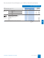
■ Technical specifications
Short-circuit breaking capacity
Size
I
II
Type
3WL11
3WL12
Switching capacity class
N
S
N
III
3WL13
S
H
H
up to AC 415 V
Icu
kA
50
65
55
80
100
100
Ics
kA
50
65
55
80
100
100
Icm
kA
105
143
121
176
220
220
up to AC 500 V
Icu
kA
50
65
55
80
100
100
Ics
kA
50
65
55
80
100
100
Icm
kA
105
143
121
176
220
220
85
up to AC 690 V
Icu
kA
42
50
50
75
85
Ics
kA
42
50
50
75
85
85
Icm
kA
88
105
105
165
187
187
50
up to AC 1000 V
5
Icu
kA
–
–
–
–
45
Ics
kA
–
–
–
–
45
50
Icm
kA
–
–
–
–
95
105
Rated short-time withstand current Icw of circuit-breakers
Size
I
II
Type
3WL11
3WL12
III
Switching capacity class
N
S
N
S
H
H
3WL13
0.5 s
kA
42
65
55
80
100
100
1s
kA
42
50
55
65
80
100
2s
kA
29.5
35
39
46
651)/702)
80
3s
kA
24
29
32
37
501)/652)
65
Short-circuit breaking capacity Icc of non-automatic circuit-breakers
Size
I
II
Type
3WL11
3WL12
III
Switching capacity class
N
S
N
S
H
H
3WL13
up to AC 500 V
kA
42
65
55
80
100
100
up to AC 690 V
kA
42
50
50
75
85
85
1) Size II with In max ≤ 2500 A.
2) Size II with In max = 3200 A.
5/20
Siemens LV 30 · 2004
Circuit-Breakers/Non-Automatic Circuit-Breakers up to 6300 A,
SENTRON WL
General data
Size
I
Type
up to
3WL11 12 3WL11 16 3WL12 08 3WL12 10 3WL12 12 3WL12 16 3WL12 20
3WL11 10
Rated current In at 40 °C, at 50/60 Hz
Main conductor
Neutral conductor (only with 4-pole versions)
II
A up to 1000 1250
A up to 1000 1250
1600
1600
800
800
1000
1000
1250
1250
1600
1600
2000
2000
Rated operating voltage Ue at 50/60 Hz
(1000 V design, see options)
AC V up to 690
up to 690
up to 690
up to
690/1000
up to
690/1000
up to
690/1000
up to
690/1000
up to
690/1000
Rated insulation voltage Ui
AC V 1000
1000
1000
1000
1000
1000
1000
1000
kV 12
kV 4
kV 2.5
12
4
2.5
12
4
2.5
12
4
2.5
12
4
2.5
12
4
2.5
12
4
2.5
12
4
2.5
yes
yes
yes
yes
yes
yes
yes
–25/+70
–40/+70
–25/+70
–40/+70
–25/+70
–40/+70
–25/+70
–40/+70
–25/+70
–40/+70
–25/+70
–40/+70
–25/+70
–40/+70
A 1000
A 1000
A 1000
1250
1250
1210
1600
1600
1490
800
800
800
1000
1000
1000
1250
1250
1250
1600
1600
1600
2000
2000
2000
W 100
W 195
105
205
150
350
40
85
45
95
80
165
85
175
180
320
Rated impulse withstand voltage Uimp
Main circuits
Auxiliary circuits
Control circuits
Isolating function to EN 60947-2
yes
Utilization category
B
Permissible ambient temperature
in operation (in operation with LCD max. 55 °C)
Storage (special conditions for LCDs must be
observed)
Permissible load
at rear horizontal main
circuit connections
°C –25/+70
°C –40/+70
up to 55 °C (Cu bare)
up to 60 °C (Cu bare)
up to 70 °C (Cu painted
black)
Power loss at In
with AC symmetrical load
Fixed-mounted circuit-breaker
Withdrawable circuit-breaker
Operating times
Make-time
Break-time
ms 35
ms 38
35
38
35
38
35
34
35
34
35
34
35
34
35
34
Electr. make-time (via activation solenoid)2)
Electr. break-time (via shunt release)
ms 80
ms 73
80
73
80
73
100
73
100
73
100
73
100
73
100
73
Electr. break-time (instantaneous undervoltage release)
Break-time through ETU, instantaneous short-circuit
release
ms 73
ms 501)
73
501)
73
501)
10 000
20 000
10 000
–
20 000
1/h 60
1/h –
ms 80
Operating cycles
Operating cycles
Operating cycles
Operating cycles
Operating cycles
Operating frequency
690 V design
1000 V design
Minimum interval between tripping operation by overcurrent release and next making operation of the circuit-breaker (only with autom. mechanical resetting of
the lockout device)
10 000
20 000
10 000
–
20 000
73
501)
73
501)
73
501)
73
501)
10 000
20 000
10 000
–
20 000
10 000
15 000
7500
1000
15 000
10 000
15 000
7500
1000
15 000
10 000
15 000
7500
1000
15 000
10 000
15 000
7500
1000
15 000
10 000
15 000
7500
1000
15 000
60
–
60
–
60
20
60
20
60
20
60
20
60
20
80
80
80
80
80
80
80
3 0 ° 3 0 °
Service position
3 0 °
3 0 °
D h max.
= 1 mm
Service life
mechanical (without maint.)
mechanical (with maint.)3)
electrical (without maint.)
1000 V design
electrical (with maint.)3)
73
501)
and/
or
N S E 0
0 0 0 6 1
N S E 0
NSE00927
0 0 0 6 2
IP20 without cabinet door, IP30 with door mounting frame, IP55 with cover
Degree of protection
Main conductor
minimum
cross-sections
Copper bars,
bare
Qty. 1 ×
mm2 60 × 10
2×
40 × 10
2×
50 × 10
1×
50 × 10
1×
60 × 10
2×
40 × 10
2×
50 × 10
3×
50 × 10
Copper bars,
painted black
Qty. 1 ×
mm2 60 × 10
2×
40 × 10
2×
50 × 10
1×
50 × 10
1×
60 × 10
2×
40 × 10
2×
50 × 10
3×
50 × 10
Auxiliary conductors (Cu)
Max. no. of
auxiliary conductors ×
cross-section
(solid/stranded)
Standard connection = strainrelief clamp
without end sleeve
with end sleeve to
DIN 46228 T.2
with twin end sleeve
2 × 0.5 mm2 (AWG 20) to 2 × 1.5 mm2 (AWG 16); 1 × 2.5 mm2 (AWG 14)
1 × 0.5 mm2 (AWG 20) to 1 × 1.5 mm2 (AWG 16)
2 × 0.5 mm2 (AWG 20) to 2 × 1.5 mm2 (AWG 16)
optional conn. = tension spring
without end sleeve
with end sleeve to
DIN 46228 T.2
2 × 0.5 mm2 (AWG 20) to 2 × 2.5 mm2 (AWG 14)
2 × 0.5 mm2 (AWG 20) to 2 × 1.5 mm2 (AWG 16)
Weights 3-pole
Fixed-mounted circ.-br.
Withdrawable circ.-br.
Guide frame
kg 43
kg 45
kg 25
43
45
25
43
45
25
56
60
31
56
60
31
56
60
31
56
60
31
56
60
31
4-pole
Fixed-mounted circ.-br.
Withdrawable circ.-br
Guide frame
kg 50
kg 54
kg 30
50
54
30
50
54
30
67
72
37
67
72
37
67
72
37
67
72
37
67
72
37
1) Break-time on instantaneous short-circuit release with ETU15B = 85 ms.
2) Make-time via activation solenoid for synchronization purposes
(short-time excited) 50 ms.
3) Maintenance means: replace main contact elements and arc chutes (see
Operator's Guide).
Siemens LV 30 · 2004
5/21
5
Circuit-Breakers/Non-Automatic Circuit-Breakers up to 6300 A,
SENTRON WL
General data
Size
II
Type
3WL12 25
Rated current In at 40 °C, at 50/60 Hz
Main conductor
Neutral conductor (only on 4-pole versions)
A 2500
A 2500
3WL13 40
3WL13 50
3WL13 63
3200
3200
4000
4000
5000
5000
6300
6300
Rated operating voltage Ue at 50/60 Hz
(1000 V design, see options)
AC V up to 690/1000
up to 690/1000
up to 690/1000
up to 690/1000
up to 690/1000
Rated insulation voltage Ui
AC V 1000
1000
1000
1000
1000
kV 12
kV 4
kV 2.5
12
4
2.5
12
4
2.5
12
4
2.5
12
4
2.5
yes
yes
yes
yes
Rated impulse withstand voltage Uimp
Main circuits
Auxiliary circuits
Control circuits
Isolating function to EN 60947-2
yes
Utilization category
B (except switching capacity class DC)
Permissible ambient temperature
in operation (in operation with LCD max. 55 °C)
Storage (special conditions for LCDs must be observed)
Permissible load
°C –25/+70
°C –40/+70
–25/+70
–40/+70
–25/+70
–40/+70
–25/+70
–40/+70
–25/+70
–40/+70
A 2500
A 2500
A 2280
3200
3020
2870
4000
4000
4000
5000
5000
5000
5920
5810
5500
W 270
W 520
410
710
520
810
630
1050
900
1600
up to 55 °C (Cu bare)
up to 60 °C (Cu bare)
up to 70 °C (Cu painted
black)
Power loss at In
with AC symmetrical load
Fixed-mounted circuit-breaker
Withdrawable circuit-breaker
Operating times
Make-time
Break-time
ms
ms
35
34
35
34
35
34
35
34
35
34
Electr. make-time (via activation solenoid) 2)
Electr. break-time (via shunt release)
ms 100
ms 73
100
73
100
73
100
73
100
73
Electr. break-time (instantaneous undervoltage release)
Break-time through ETU, instantaneous short-circuit
release
ms
ms
73
50
73
50
73
50
Service life
mechanical (without maint.)
mechanical (with maint.)3)
electrical (without maint.)
1000 V design
electrical (with maint.)3)
73
501)
Operating cycles 10000
Operating cycles 15000
Operating cycles 7500
Operating cycles 1000
Operating cycles 15000
Operating frequency
690 V design
1000 V design
Minimum interval between tripping operation by over-current release and next making operation of the circuitbreaker (only with autom. mechanical resetting of the lockout device)
73
501)
10000
15000
4000
1000
15000
5000
10000
2000
1000
10000
5000
10000
2000
1000
10000
5000
10000
2000
1000
10000
1/h 60
1/h 20
60
20
60
20
60
20
60
20
ms 80
80
80
80
80
3 0 ° 3 0 °
Service position
3 0 °
3 0 °
and/
or
N S E 0 _ 0 0 0 6 1
D h max.
= 1 mm
5
III
3WL12 32
NSE00927
N S E 0 _ 0 0 0 6 2
IP20 without cabinet door, IP30 with door mounting frame, IP55 with cover
Degree of protection
Main conductor
minimum
cross-sections
Copper bars,
bare
Qty. 2 ×
mm2 100 × 10
3×
100 × 10
4x
100 x 10
6x
100 x 10
6x
120 x 10
Copper bars,
painted black
Qty. 2 ×
mm2 100 × 10
3×
100 × 10
4×
100 × 10
6×
100 × 10
6×
120 × 10
Auxiliary conductors (Cu)
Max. no. of
auxiliary conductors ×
cross-section
(solid/stranded)
Standard connection = strain-relief
clamp
without end sleeve
with end sleeve to
DIN 46228 T.2
with twin end sleeve
2 × 0.5 mm2 (AWG 20) to 2 × 1.5 mm2 (AWG 16); 1 × 2.5 mm2 (AWG 14)
1 × 0.5 mm2 (AWG 20) to 1 × 1.5 mm2 (AWG 16)
2 × 0.5 mm2 (AWG 20) to 2 × 1.5 mm2 (AWG 16)
optional connection = tension spring
2 × 0.5 mm2 (AWG 20) to 2 × 2.5 mm2 (AWG 14)
without end sleeve
2 × 0.5 mm2 (AWG 20) to 2 × 1.5 mm2 (AWG 16)
with end sleeve to
DIN 46228 T.2
Weights 3-pole
4-pole
Fixed-mounted circuitbreaker
Withdrawable circuit-breaker
Guide frame
kg 59
64
82
82
90
kg 63
kg 39
68
45
88
60
88
60
96
70
Fixed-mounted circuitbreaker
Withdrawable circuit-breaker
Guide frame
kg 71
77
99
99
108
kg 76
kg 47
82
54
106
84
106
84
108
119
1) Break-time on instantaneous short-circuit release with ETU15B = 85 ms.
2) Make-time via activation solenoid for synchronization purposes
(short-time excited) 50 ms.
5/22
Siemens LV 30 · 2004
3) Maintenance means: replace main contact elements and arc chutes
(see Operator's Guide).
Circuit-Breakers/Non-Automatic Circuit-Breakers up to 6300 A,
SENTRON WL
General data
Size
I ... III
Manual operating mechanism with mechanical closing
Closing/
charging stored-energy
feature
N ≤ 230
9
Max. force required to operate the hand lever
Required number of strokes on the hand lever
Manual operating mechanism with mechanical and electrical closing
Charging stored-energy
feature
Closing solenoid (CC)
Operating range
0.85 ... 1.1 × Us
Extended operating range for battery operation
for DC 24 V, DC 48 V
DC 60 V, DC 110 V
DC 220 V
Power input
AC/DC
Minimum command duration at Us for the closing solenoid
0.7 ... 1.26 × Us
VA/W 15/15
ms 60
Short-circuit protection
1 A TDz (time-lag)/1 A
Smallest permissible DIAZED fuse (operational class gL)/
miniature circuit-breaker with C-characteristic
Manual/motorized operating mechanism with mechanical and electrical closing
Manual operating mechanism
Motor
For data see above.
Extended coil voltage tolerance for battery operation
for DC 24 V, DC 48 V
DC 60 V, DC 110 V
DC 220 V
Power input to motor
AC/DC
0.7 ... 1.26 × Us
VA/W 110/110
s ≤ 10
Time required to charge the stored-energy mechanism at 1 × Us
Closing solenoid
For motor and
closing solenoid
5
0.85 ... 1.1 × Us
Operating range
For data see above.
Short-circuit protection
2 A TDz (time-lag)/1 A
Motor and closing solenoid for the same rated control supply voltages
Smallest permissible DIAZED fuse (operational class gL)/
miniature circuit-breaker with C-characteristic (for different
rated control supply voltages
at Us = 24–30 V
at Us = 48–60 V
at Us = 110–127 V
at Us = 220–250 V
2A
2A
1A
1A
Electronic trip unit signals
Protection functions to
EN 60947;
current indication ≤ 5 %;
measurement functions
base quantities ≤ 1 %;
measurement functions
derived quantities ≤ 4 %
Measuring accuracy of the electronic trip unit
Auxiliary releases
shunt release (ST)
(F1, F2)
For continuous command
(100 % ON-time),
locks out on momentarycontact commands
Operating value
pickup
0.85 ... 1.1 × Us
Operating range
Extended operating range
for battery operation
for DC 24 V, DC 48 V
DC 60 V, DC 110 V
DC 220 V
Rated control supply voltage Us
AC 50/60 Hz
DC
Power input
AC/DC
Minimum command duration at Us
Opening time of circuit-breaker
at Us = 100 %
Rated control supply voltage Us
AC 50/60 Hz
DC
V 110; 230
V 24; 30; 48; 60; 110; 220
VA/W 15/15
ms 80
1 A TDz (time-lag)/1 A
V 110; 230
V 110; 220
0.85 ... 1.1 × Us
Operating range
Power input
0.7 ... 1.26 × Us
ms 60
AC/DC
Short-circuit protection
Smallest permissible DIAZED fuse (operational class gL)/
miniature circuit-breaker with C-characteristic
With stored energy feature
consisting of shunt release
and capacitor storage
device
> 0.7 × Us
(circuit-breaker is tripped)
AC/DC
VA/W 1/1
Storage time at Us/recharging time at Us
max. 5 min/min. 5 s
Opening time of circuit-breaker, short-circuit protection
as with "for continuous command"
Siemens LV 30 · 2004
5/23
Circuit-Breakers/Non-Automatic Circuit-Breakers up to 6300 A,
SENTRON WL
General data
Size
I ... III
Auxiliary releases
Undervoltage release
UVR (F3) and
UVR-td (F4)
Operating values
≥ 0.85 × Us (circuit-breaker can
be closed)
0.35 ... 0.7× Us
(circuit-breaker is tripped)
pickup
dropout
0.85 ... 1.1
Operating range
Extended operating range for battery operation
for DC 24 V, DC 30 V,
DC 48 V, DC 110 V,
DC 220 V
Rated control supply voltage Us
AC 50/60 Hz
DC
Power input (pickup/continuous duty)
AC
DC
Opening time of circuit-breaker at Us = 0
Design UVR (F3)
Instantaneous
With delay
Design UVR-td (F8)
With delay, td = 0.2 ... 3.2 s
Reset via additional NC contact – direct switching-off
5
Short-circuit protection
Smallest permissible DIAZED fuse (operational class gL)/
miniature circuit-breaker with C-characteristic
0.85 ... 1.26
V 110 ... 127/208 ... 240/380 ... 415
V 24/30/48/110/220 ... 2501)
VA 200/5
W 200/5
ms 200
ms 80
ms 200
s 0.2 ... 3.2
ms ≤ 100
1 A TDz (time-lag) 1 A
Contact position-driven auxiliary switches (S1, S2, S3, S4, S7, S8)
Rated insulation voltage Ui
AC/DC V 500
Rated operating voltage Ue
Switching capacity
AC/DC V 500
AC
50/60 Hz
DC
Short-circuit protection
5/24
A 10
A 4
Rated operating voltage Ue
Rated operating current
Ie/DC-12
Ie/DC-13
V 24
48
A 10
A 8
8
4
Largest permissible DIAZED fuse (operational class gL)
Largest permissible miniature circuit-breaker with C-characteristic
1) 24 V and 30 V only with undervoltage release UVR (F3).
Siemens LV 30 · 2004
V 24 ... 230
Rated operating voltage Ue
Rated operating current
Ie/AC-12
Ie/AC-15
380/400
500
10
3
10
2
110
220
3.5
1.2
10 A TDz, 10 A Dz
10 A
1
0.4
Circuit-Breakers/Non-Automatic Circuit-Breakers up to 6300 A,
SENTRON WL
General data
Size
I ... III
Ready-to-close signaling switch (S20) (to DIN VDE 0630)
Switching capacity
AC
Rated operating voltage Ue
Rated operating current Ie
V 110
A
0.14
220
0.1
DC
Rated operating voltage Ue
Rated operating current Ie
V 24
A 0.2
220
0.1
Short-circuit protection
Largest permissible DIAZED fuse (operational class gL)
2A
"Tripped" switch
Signal duration after tripping
on req.
Dz (quick)
Tripped signaling switch (S24) (to DIN VDE 0630)
Switching capacity
AC
Rated operating voltage Ue
Rated operating current Ie/AC-12
V 230
A 6
DC
Rated operating voltage Ue
Rated operating current Ie/DC-12
V 24
A 6
110
0.4
220
0.2
Short-circuit protection
Largest permissible DIAZED fuse (operational class gL)
6A
"Tripped" switch
Signal duration after tripping
until manual or electrical
remote-controlled reset (option)
Dz (quick)
Position indicator switch on guide frame
Type of contact
Signal:
AC 50/60 Hz
DC
Rated insulation voltage Ui
Rated operating voltage Ue
Switching capacity
or
1W
1W
1W
5
V 440
V 250
V 250
Rated operating
current Ie
Ie/AC-12
Ie/AC-15
Ie/DC-12
Ie/DC-13
Short-circuit protection
3W
2W
1W
"Circuit-breaker in connected position"
"Circuit-breaker in test position"
"Circuit-breaker in disconnected
position"
Largest permissible DIAZED fuse (operational class gL)
Largest permissible miniature circuit-breaker with C-characteristic
110/127 V 13 A, 220/230 V 13 A,
320/400 V 0.6 A
110/127 V 5 A, 220/230 V 4 A,
320/440 V 3 A
24 V 13 A, 30 V 10 A, 48 V 2.5 A,
110 V 0.8 A, 220/250 V 0.6 A
24 V 3.0 A, 220/250 V 0.1 A
8 A TDz (slow)
8 A TDz (slow)
Siemens LV 30 · 2004
5/25
Circuit-Breakers/Non-Automatic Circuit-Breakers up to 6300 A,
SENTRON WL
General data
Functional overview of the electronic trip unit system
Protection functions
Configuration via
Overload protection
Function can be switched on/off
Setting range IR = In × ...
overload protection
L Switchable
(I t- or I t-dependent function)
2
R
4
Setting range for time-lag class tR at I2t
10 s fixed
Setting range for time-lag class tR at I4t
–
Thermal image can be switched on/off
–
R
Phase loss sensitivity
–
Neutral conductor protection
–
Function can be switched on/off
–
N conductor setting range IN = In × ...
–
Short-time delayed short-circuit protection
–
Function can be switched on/off
–
Setting range Isd = In × ...
–
s d
–
Setting range for delay time tsd
Switchable short-time delayed short-circuit protection
–
s d
(I2t-dependent function)
Setting range for delay time tsd at I2t
–
Zone Selective Interlocking function
–
i
Instantaneous short-circuit protection
✓
N S E 0 _ 0 0 8 8 8 b
–
Function can be switched on/off
Setting range Ii = In × ...
2-3-4-5-6-7-8
Ground-fault protection
–
–
Tripping and alarm function
Tripping function can be switched on/off
–
Alarm function can be switched on/off
–
Detection of the ground-fault current via summation cur- –
rent formation with internal or external neutral conductor
g
transformer
Detection of ground-fault current via external transformer –
Setting range of the operating current Ig for release
–
g
Setting range of the operating current Ig for alarm
–
N S E 0 _ 0 0 8 8 9 a
–
Setting range of the delay time tg
Switchable ground-fault protection characteristic
–
(I2t-dependent function)
Setting range for delay time tg at I2t
–
Zone Selective Interlocking G-function
–
Parameter sets switchable
–
Switchable between parameter sets A and B
LCD
Alphanumeric LCD (4-line)
–
Graphical LCD (24 V, external power supply required)
–
Communication
–
CubicleBUS integrated
Communication-capable via PROFIBUS DP
–
Measurement function
–
Measurement function-capable with meas. function/meas. function Plus
LED display
Electronic trip unit active
✓
Alarm
✓
✓
ETU fault
L-release
–
S-release
–
–
I-release
N-release
–
NSE00890
G-release
–
–
G-alarm
Release via extended protection function
–
Communication
–
Signals from signaling switches with external CubicleBUS modules (Opto or relays)
–
Overload warning
Load shedding, load receiving
–
–
Leading signal overload release 200 ms
Temperature alarm
–
Phase unbalance
–
–
Instantaneous short-circuit release
Short-time delayed short-circuit release
–
Overload release
–
–
Neutral conductor release
NSE00891
Ground-fault protection release
–
Ground-fault alarm
–
–
Auxiliary relay
ETU fault
–
N
S
5
ETU15B
D
✓
–
0.5-0.6-0.7-0.80.9-1
–
I
G
Increment size for adjustment of menu/comm or comm
From ... to
Increment size From ... to
Increment size
0 ... 1
0.1
1 000 ... 1 600
50
1 ... 100
1
1600 ... 10 000 100
100 ... 500
5
10 000 ... max. 1 000
500 ... 1 000
10
5/26
Siemens LV 30 · 2004
ETU25B
D
✓
–
0.4-0.45-0.5-0.55-0.60.65-0.7-0.8-0.9-1
–
ETU27B
D&S
✓
–
0.4-0.45-0.5-0.55-0.60.65-0.7-0.8-0.9-1
–
10 s fixed
–
–
at tsd = 20 ms (M)
–
–
–
✓
–
1.25-1.5-2-2.5-3-4-6-8-10-12
0-M-100-200-300-400
–
10 s fixed
–
–
at tsd = 20 ms (M)
✓
✓
1
✓
–
1.25-1.5-2-2.5-3-4-6-8-10-12
0-M-100-200-300-400
–
–
–
✓
–
fixed for Ii ≥ 20 × In, max. 50 kA
–
–
–
–
–
–
–
✓
–
fixed for Ii ≥ 20 × In, max. 50 kA
✓ fixed-mounting
–
✓
–
✓
–
–
–
–
–
–
A-B-C-D-E
–
100-200-300-400-500 ms
–
–
–
–
–
–
–
–
–
–
–
–
–
–
–
–
–
✓
✓
✓
✓
✓
✓
–
–
–
–
–
✓
✓
✓
✓
✓
✓
✓
✓
–
–
–
–
–
–
–
–
–
–
–
–
–
–
–
–
–
–
–
–
–
–
–
–
–
–
–
–
–
Delay-time figures given in ms.
✓ Available.
M = motor protection, corresponds to 20 ms.
– Not available.
D = rotary coding switch
❑ Optional.
D & S = rotary coding switch and sliding-dolly switch
K = communication
M/K = menu/communication
Circuit-Breakers/Non-Automatic Circuit-Breakers up to 6300 A,
SENTRON WL
General data
Protection functions
Configuration via
Overload protection
Function can be switched on/off
Setting range IR = In × ...
ETU45B:
D&S
✓
–
0.4-0.45-0.5-0.55-0.60.65-0.7-0.8-0.9-1
✓
Switchable overload protection
(I2t- or I4t-dependent function)
Setting range for time-lag class tR at I2t
2-3-5-5.5-8-10-14-17-21-25-30 s
Setting range for time-lag class tR at I4t
1-2-3-4-5 s
Thermal image can be switched on/off
✓
Phase loss sensitivity
at tsd = 20 ms (M)
✓
Neutral conductor protection
Function can be switched on/off
✓
N conductor setting range IN = In × ...
0.5 ... 1
✓
Short-time delayed short-circuit protection
Function can be switched on/off
✓
Setting range Isd = In × ...
1.25-1.5-2-2.5-3-4-6-8-10-12
Setting range for delay time tsd
M-100-200-300-400 ms
Switchable short-time delayed short-circuit protection
✓
(I2t-dependent function)
Setting range for delay time tsd at I2t
100-200-300-400 ms
Zone Selective Interlocking function
by CubicleBUS module
Instantaneous short-circuit protection
✓
✓
Function can be switched on/off
Setting range Ii = In × ...
1.5-2.2-3-4-6-8-10-12-0.8 x Ics
Ground-fault protection
❑ Module can be retrofitted
✓
Tripping and alarm function
Tripping function can be switched on/off
✓
Alarm function can be switched on/off
–
Detection of the ground-fault current via summation cur- ✓
rent formation with internal or external neutral conductor
transformer
Detection of ground-fault current via external transformer ✓
Setting range of the operating current Ig for release
A-B-C-D-E
Setting range of the operating current Ig for alarm
A-B-C-D-E
100-200-300-400-500 ms
Setting range of the delay time tg
Switchable ground-fault protection characteristic
✓
(I2t-dependent function)
Setting range for delay time tg at I2t
100-200-300-400-500 ms
Zone Selective Interlocking G-function
by CubicleBUS module
Parameter set switchover
–
Switchable between parameter set A and B
LCD
Alphanumeric LCD (4-line)
❑
Graphical LCD (24 V, external power supply required)
–
Communication
✓
CubicleBUS integrated
Communication-capable via PROFIBUS DP
✓
Measurement function
✓
Measurement function-capable with meas. function/meas. function Plus
LED display
Electronic trip unit active
✓
Alarm
✓
✓
ETU fault
L-release
✓
S-release
✓
✓
I-release
N-release
✓
G-release
✓ (only with ground-fault prot. mod.)
G-alarm
✓ (only with ground-fault prot. mod.)
Release via extended protection functions
✓
Communication
✓
Signals from signaling switches with external CubicleBUS modules (optical or relays)
✓
Overload warning
Load shedding, load receiving
✓
✓
Leading signal overload release 200 ms
Temperature alarm
✓
Phase unbalance
✓
✓
Instantaneous short-circuit release
Short-time delayed short-circuit release
✓
Overload release
✓
✓
Neutral conductor release
Ground-fault protection release
✓ (only with ground-fault prot. mod.)
Ground-fault alarm
✓ (only with ground-fault prot. mod.)
Auxiliary relay
✓
ETU fault
✓
ETU55B
K
✓
✓
0.4 ... 1
ETU76B:
M/K
✓
✓
0.4 ... 1
✓
✓
2 ... 30 s
1 ... 5 s
✓
✓ (on/off)
✓
✓
0.2 ... 2
✓
✓
1.25 In ... 0.8 × Icw
M-80 ... 4000 ms
✓
2 ... 30 s
1 ... 5 s
✓
✓ (on/off)
✓
✓
0.2 ... 2
✓
✓
1.25 In ... 0.8 × Icw
M-80 ... 4000 ms
✓
100 ... 400 ms
by CubicleBUS module
✓
✓
1.5 × In ... 0.8 × Ics
❑ Module can be retrofitted
✓
✓
✓
✓
100 ... 400 ms
by CubicleBUS module
✓
✓
1.5 × In ... 0.8 × Ics
❑ Module can be retrofitted
✓
✓
✓
✓
✓
A ... E
A ... E
100 ... 500 ms
✓
✓
A ... E
A ... E
100 ... 500 ms
✓
100 ... 500 ms
by CubicleBUS module
100 ... 500 ms
by CubicleBUS module
✓
✓
–
–
–
✓
✓
✓
✓
✓
✓
✓
✓
✓
✓
✓
✓
✓
✓
✓ (only with ground-fault prot. mod.)
✓ (only with ground-fault prot. mod.)
✓
✓
✓
✓
✓
✓
✓
✓
✓
✓ (only with ground-fault prot. mod.)
✓ (only with ground-fault prot. mod.)
✓
✓
✓
✓
✓
✓
✓
✓
✓
✓
✓
✓ (only with ground-fault prot. mod.)
✓ (only with ground-fault prot. mod.)
✓
✓
✓
✓
✓
✓
✓
✓
✓
✓
✓
✓ (only with ground-fault prot. mod.)
✓ (only with ground-fault prot. mod.)
✓
✓
Setting range of the operating current Ig
Size III
Size I and Size II
400 A
A
100 A
600 A
B
300 A
800 A
C
600 A
1000 A
D
900 A
1200 A
E
1200 A
Siemens LV 30 · 2004
5/27
5
Circuit-Breakers/Non-Automatic Circuit-Breakers up to 6300 A,
SENTRON WL
3-pole, fixed-mounted design
■ Selection and ordering data
Size
Max. rated circuit- Rated current1)
breaker current
In
In max.
ECO switching capacity N,
Icu/440 V
A
kA
DT
B
B
B
B
B
A
PS*
Order No.
Order No. supplement
see Page 5/36
Weight Standard switching capacity S,
per PU Icu/440 V
approx.
Order No.
Order No. supplement
see Page 5/36
kg
PS*
Weight
per PU
approx.
kA
DT
kg
65
65
65
65
65
B
B
B
B
B
3WL11 06-3@@32-....
3WL11 08-3@@32-....
3WL11 10-3@@32-....
3WL11 12-3@@32-....
3WL11 16-3@@32-....
1 unit
1 unit
1 unit
1 unit
1 unit
43.000
43.000
43.000
43.000
43.000
80
80
80
80
56.000 80
59.000 80
80
B
B
B
B
B
B
B
3WL12 08-3@@32-....
3WL12 10-3@@32-....
3WL12 12-3@@32-....
3WL12 16-3@@32-....
3WL12 20-3@@32-....
3WL12 25-3@@32-....
3WL12 32-3@@32-....
1 unit
1 unit
1 unit
1 unit
1 unit
1 unit
1 unit
56.000
56.000
56.000
56.000
56.000
59.000
64.000
43.000
43.000
43.000
43.000
43.000
65
65
65
65
65
B
B
B
B
B
3WL11 06-3@@31-....
3WL11 08-3@@31-....
3WL11 10-3@@31-....
3WL11 12-3@@31-....
3WL11 16-3@@31-....
1 unit
1 unit
1 unit
1 unit
1 unit
43.000
43.000
43.000
43.000
43.000
80
80
80
80
56.000 80
59.000 80
80
B
B
B
B
B
B
B
3WL12 08-3@@31-....
3WL12 10-3@@31-....
3WL12 12-3@@31-....
3WL12 16-3@@31-....
3WL12 20-3@@31-....
3WL12 25-3@@31-....
3WL12 32-3@@31-....
1 unit
1 unit
1 unit
1 unit
1 unit
1 unit
1 unit
56.000
56.000
56.000
56.000
56.000
59.000
64.000
43.000
43.000
43.000
43.000
43.000
65
65
65
65
65
B
B
B
B
B
3WL11 06-3@@33-....
3WL11 08-3@@33-....
3WL11 10-3@@33-....
3WL11 12-3@@33-....
3WL11 16-3@@33-....
1 unit
1 unit
1 unit
1 unit
1 unit
43.000
43.000
43.000
43.000
43.000
80
80
80
80
56.000 80
59.000 80
80
B
B
B
B
B
B
B
3WL12 08-3@@33-....
3WL12 10-3@@33-....
3WL12 12-3@@33-....
3WL12 16-3@@33-....
3WL12 20-3@@33-....
3WL12 25-3@@33-....
3WL12 32-3@@33-....
1 unit
1 unit
1 unit
1 unit
1 unit
1 unit
1 unit
56.000
56.000
56.000
56.000
56.000
59.000
64.000
43.000
43.000
43.000
43.000
43.000
65
65
65
65
65
B
B
B
B
B
3WL11 06-3@@34-....
3WL11 08-3@@34-....
3WL11 10-3@@34-....
3WL11 12-3@@34-....
3WL11 16-3@@34-....
1 unit
1 unit
1 unit
1 unit
1 unit
43.000
43.000
43.000
43.000
43.000
80
80
80
80
56.000 80
59.000 80
80
B
B
B
B
B
B
B
3WL12 08-3@@34-....
3WL12 10-3@@34-....
3WL12 12-3@@34-....
3WL12 16-3@@34-....
3WL12 20-3@@34-....
3WL12 25-3@@34-....
3WL12 32-3@@34-....
1 unit
1 unit
1 unit
1 unit
1 unit
1 unit
1 unit
56.000
56.000
56.000
56.000
56.000
59.000
64.000
Horizontal main circuit connection
I
I
I
I
I
630
800
1000
1250
1600
630
800
1000
1250
1600
50
50
50
50
50
II
II
II
II
II
II
II
800
1000
1250
1600
2000
2500
3200
800
1000
1250
1600
2000
2500
3200
–
–
–
–
55
55
–
B
B
3WL11 06-2@@32-....
3WL11 08-2@@32-....
3WL11 10-2@@32-....
3WL11 12-2@@32-....
3WL11 16-2@@32-....
–
–
–
–
3WL12 20-2@@32-....
3WL12 25-2@@32-....
–
1 unit
1 unit
1 unit
1 unit
1 unit
1 unit
1 unit
43.000
43.000
43.000
43.000
43.000
Vertical main circuit connection
5
I
I
I
I
I
630
800
1000
1250
1600
630
800
1000
1250
1600
50
50
50
50
50
II
II
II
II
II
II
II
800
1000
1250
1600
2000
2500
3200
800
1000
1250
1600
2000
2500
3200
–
–
–
–
55
55
–
B
B
B
B
B
B
B
3WL11 06-2@@31-....
3WL11 08-2@@31-....
3WL11 10-2@@31-....
3WL11 12-2@@31-....
3WL11 16-2@@31-....
–
–
–
–
3WL12 20-2@@31-....
3WL12 25-2@@31-....
–
1 unit
1 unit
1 unit
1 unit
1 unit
1 unit
1 unit
Front main circuit connection, single hole
I
I
I
I
I
630
800
1000
1250
1600
630
800
1000
1250
1600
50
50
50
50
50
II
II
II
II
II
II
II
800
1000
1250
1600
2000
2500
3200
800
1000
1250
1600
2000
2500
3200
–
–
–
–
55
55
–
B
B
B
B
B
B
B
3WL11 06-2@@33-....
3WL11 08-2@@33-....
3WL11 10-2@@33-....
3WL11 12-2@@33-....
3WL11 16-2@@33-....
–
–
–
–
3WL12 20-2@@33-....
3WL12 25-2@@33-....
–
1 unit
1 unit
1 unit
1 unit
1 unit
1 unit
1 unit
Front main circuit connection, double hole
I
I
I
I
I
630
800
1000
1250
1600
630
800
1000
1250
1600
50
50
50
50
50
II
II
II
II
II
II
II
800
1000
1250
1600
2000
2500
3200
800
1000
1250
1600
2000
2500
3200
–
–
–
–
55
55
–
B
B
B
B
B
B
B
Non-automatic circuit-breakers2)
without electronic trip unit
without electronic trip unit, communication/
measurement function optional3) ■
3WL11 06-2@@34-....
3WL11 08-2@@34-....
3WL11 10-2@@34-....
3WL11 12-2@@34-....
3WL11 16-2@@34-....
–
–
–
–
3WL12 20-2@@34-....
3WL12 25-2@@34-....
–
1 unit
1 unit
1 unit
1 unit
1 unit
1 unit
1 unit
Order No. supplements
Order No. supplements
AA
AB
AA
AB
Design without ground-fault protection
ETU15B: protection functions LI
ETU25B: protection functions LSI
ETU45B: protection functions LSIN4)
ETU45B: protection functions LSIN4) with 4-line display
ETU55B: protection functions LSIN4)
ETU76B: prot. functions LSIN4) with pixel graphics display
BB
CB
EB
FB
JB
NB
BB
CB
EB
FB
JB
NB
Design with ground-fault protection
ETU27B: protection functions LSING4)
ETU45B: protection functions LSING4)6)
ETU45B: protection functions LSING4) with 4-line display6)
ETU55B: protection functions LSING4)6)
ETU76B: prot. functions LSING4) w. pixel graphic display6)
DG
EG
FG
JG
NG
DG
EG
FG
JG
NG
Electronic trip units
Standard Order No. supplements (for further Order No. supplements see Page 5/36)
Manual operating mechanism with mechanical closing
1AA2
Without 1st and 2nd aux. releases; aux. sw. 2 NC + 2 NO
1AA2
For footnotes see Page 5/29.
5/28
Siemens LV 30 · 2004
* This quantity or a multiple thereof can be ordered.
Circuit-Breakers/Non-Automatic Circuit-Breakers up to 6300 A,
SENTRON WL
3-pole, fixed-mounted design
Size
Max. rated circuit-breaker
current
In max.
Rated current1)
In
High switching capacity H, Icu/440 V
A
A
kA
DT
PS*
Order No.
Order No. supplements
see Page 5/36
Weight
per PU
approx.
kg
Horizontal main circuit connection
II
II
II
II
II
II
II
800
1000
1250
1600
2000
2500
3200
800
1000
1250
1600
2000
2500
3200
100
100
100
100
100
100
100
B
B
B
B
B
B
B
3WL12 08-4@@32-....
3WL12 10-4@@32-....
3WL12 12-4@@32-....
3WL12 16-4@@32-....
3WL12 20-4@@32-....
3WL12 25-4@@32-....
3WL12 32-4@@32-....
1 unit
1 unit
1 unit
1 unit
1 unit
1 unit
1 unit
56.000
56.000
56.000
56.000
56.000
59.000
64.000
III 5)
III5)
4000
5000
4000
5000
100
100
C
C
3WL13 40-4@@32-....
3WL13 50-4@@32-....
1 unit
1 unit
82.000
82.000
Vertical main circuit connection
II
II
II
II
II
II
II
800
1000
1250
1600
2000
2500
3200
800
1000
1250
1600
2000
2500
3200
100
100
100
100
100
100
100
B
B
B
B
B
B
B
3WL12 08-4@@31-....
3WL12 10-4@@31-....
3WL12 12-4@@31-....
3WL12 16-4@@31-....
3WL12 20-4@@31-....
3WL12 25-4@@31-....
3WL12 32-4@@31-....
1 unit
1 unit
1 unit
1 unit
1 unit
1 unit
1 unit
56.000
56.000
56.000
56.000
56.000
59.000
64.000
III 5)
III 5)
III 5)
4000
5000
6300
4000
5000
6300
100
100
100
C
C
C
3WL13 40-4@@31-....
3WL13 50-4@@31-....
3WL13 63-4@@31-....
1 unit
1 unit
1 unit
82.000
82.000
82.000
Front main circuit connection, single hole
II
II
II
II
II
II
II
800
1000
1250
1600
2000
2500
3200
800
1000
1250
1600
2000
2500
3200
100
100
100
100
100
100
100
B
B
B
B
B
B
B
3WL12 08-4@@33-....
3WL12 10-4@@33-....
3WL12 12-4@@33-....
3WL12 16-4@@33-....
3WL12 20-4@@33-....
3WL12 25-4@@33-....
3WL12 32-4@@33-....
1 unit
1 unit
1 unit
1 unit
1 unit
1 unit
1 unit
56.000
56.000
56.000
56.000
56.000
59.000
64.000
III 5)
4000
4000
100
C
3WL13 40-4@@33-....
1 unit
82.000
3WL12 08-4@@34-....
3WL12 10-4@@34-....
3WL12 12-4@@34-....
3WL12 16-4@@34-....
3WL12 20-4@@34-....
3WL12 25-4@@34-....
3WL12 32-4@@34-....
1 unit
1 unit
1 unit
1 unit
1 unit
1 unit
1 unit
56.000
56.000
56.000
56.000
56.000
59.000
64.000
3WL13 40-4@@34-....
1 unit
82.000
Front main circuit connection, double hole
II
II
II
II
II
II
II
800
1000
1250
1600
2000
2500
3200
800
1000
1250
1600
2000
2500
3200
100
100
100
100
100
100
100
B
B
B
B
B
B
B
III 5)
4000
4000
100
C
Order No. supplements
Non-automatic circuit-breakers2)
without electronic trip unit
without electronic trip unit, communication/measurement function optional3) ■
AA
AB
Electronic trip units
Design without ground-fault protection
ETU15B: protection functions LI5)
ETU25B: protection functions LSI
ETU45B: protection functions LSIN4)
ETU45B: protection functions LSIN4) with 4-line display
ETU55B: protection functions LSIN4)
ETU76B: protection functions LSIN4) with pixel graphics display
BB
CB
EB
FB
JB
NB
Design with ground-fault protection
ETU27B: protection functions LSING4)
ETU45B: protection functions LSING4) 6)
ETU45B: protection functions LSING4) with 4-line display 6)
ETU55B: protection functions LSING4) 6)
ETU76B: protection functions LSING4) with pixel graphics display 6)
DG
EG
FG
JG
NG
Standard Order No. supplements (for further Order No. supplements see Page 5/36)
Manual operating mechanism with mechanical closing
Without 1st and 2nd auxiliary releases; auxiliary switch 2 NC + 2 NO
Footnotes for pages 5/28 and 5/29:
1) Rated current determined by rated current module.
On the standard design the supplied module is equal to the max. circuitbreaker rated current.
If a lower rated current is required, adaptation by order code on page 5/37.
2) Permissible short-time current rating Icc and rated short-circuit making
capacity Icm for non-automatic circuit-breakers - see Page 5/20.
3) Required accessories "PROFIBUS communication setup" or "Measurement
function Plus": Order No. with "–Z" and order code "F02" or "F05" respectively, see Page 5/38.
* This quantity or a multiple thereof can be ordered.
1AA2
4) Current transformers for vectorial summation current formation or for protection of the neutral conductor and current transformers for detection of
the ground-fault current in the grounded star point of the transformer must
be ordered separately, see Page 5/46.
5) Size III circuit-breakers are not available with electronic trip unit design
ETU15B.
6) ETU45B to ETU76B with ground-fault protection module GFM AT (alarm
and tripping), see Page 5/46.
■ Start of delivery on request
Siemens LV 30 · 2004
5/29
5
Circuit-Breakers/Non-Automatic Circuit-Breakers up to 6300 A,
SENTRON WL
3-pole, withdrawable design
Size
Max. rated
circuit-breaker
current In max.
Rated current1) ECO switching capacity N,
In
Icu/440 V
A
A
PS*
Order No.
Order No. supplement
see Page 5/36
kA
DT
Weight
per PU
approx.
Standard switching capacity S,
Icu/440 V
PS*
kg
kA
DT
65
65
65
65
65
B
B
B
B
B
3WL11 06-3@@35-....
3WL11 08-3@@35-....
3WL11 10-3@@35-....
3WL11 12-3@@35-....
3WL11 16-3@@35-....
1 unit
1 unit
1 unit
1 unit
1 unit
45.000
45.000
45.000
45.000
45.000
80
80
80
80
60.000 80
63.000 80
80
B
B
B
B
B
B
B
3WL12 08-3@@35-....
3WL12 10-3@@35-....
3WL12 12-3@@35-....
3WL12 16-3@@35-....
3WL12 20-3@@35-....
3WL12 25-3@@35-....
3WL12 32-3@@35-....
1 unit
1 unit
1 unit
1 unit
1 unit
1 unit
1 unit
60.000
60.000
60.000
60.000
60.000
63.000
68.000
70.000
70.000
70.000
70.000
70.000
70.000
70.000
70.000
70.000
70.000
Order No.
Order No. supplement
see Page 5/36
Weight
per PU
approx.
kg
Without guide frame (for guide frames see Page 5/45)
I
I
I
I
I
630
800
1000
1250
1600
630
800
1000
1250
1600
50
50
50
50
50
II
II
II
II
II
II
II
800
1000
1250
1600
2000
2500
3200
800
1000
1250
1600
2000
2500
3200
–
–
–
–
55
55
–
B
B
B
B
B
B
B
3WL11 06-2@@35-....
3WL11 08-2@@35-....
3WL11 10-2@@35-....
3WL11 12-2@@35-....
3WL11 16-2@@35-....
–
–
–
–
3WL12 20-2@@35-....
3WL12 25-2@@35-....
–
1 unit
1 unit
1 unit
1 unit
1 unit
1 unit
1 unit
45.000
45.000
45.000
45.000
45.000
With guide frame, horizontal main circuit connection
5
I
I
I
I
I
630
800
1000
1250
1600
630
800
1000
1250
1600
50
50
50
50
50
II
II
II
II
II
II
II
800
1000
1250
1600
2000
2500
3200
800
1000
1250
1600
2000
2500
3200
–
–
–
–
55
55
–
B
B
B
B
B
B
B
3WL11 06-2@@36-....
3WL11 08-2@@36-....
3WL11 10-2@@36-....
3WL11 12-2@@36-....
3WL11 16-2@@36-....
1 unit
1 unit
1 unit
1 unit
1 unit
65
65
65
65
65
B
B
B
B
B
3WL11 06-3@@36-....
3WL11 08-3@@36-....
3WL11 10-3@@36-....
3WL11 12-3@@36-....
3WL11 16-3@@36-....
1 unit
1 unit
1 unit
1 unit
1 unit
–
–
–
–
3WL12 20-2@@36-....
3WL12 25-2@@36-....
–
80
80
80
80
1 unit 91.000 80
1 unit 102.000 80
80
B
B
B
B
B
B
B
3WL12 08-3@@36-....
3WL12 10-3@@36-....
3WL12 12-3@@36-....
3WL12 16-3@@36-....
3WL12 20-3@@36-....
3WL12 25-3@@36-....
3WL12 32-3@@36-....
1 unit 91.000
1 unit 91.000
1 unit 91.000
1 unit 91.000
1 unit 91.000
1 unit 102.000
1 unit 113.000
3WL11 06-2@@37-....
3WL11 08-2@@37-....
3WL11 10-2@@37-....
3WL11 12-2@@37-....
3WL11 16-2@@37-....
1 unit
1 unit
1 unit
1 unit
1 unit
65
65
65
65
65
B
B
B
B
B
3WL11 06-3@@37-....
3WL11 08-3@@37-....
3WL11 10-3@@37-....
3WL11 12-3@@37-....
3WL11 16-3@@37-....
1 unit
1 unit
1 unit
1 unit
1 unit
–
–
–
–
3WL12 20-2@@37-....
3WL12 25-2@@37-....
–
80
80
80
80
1 unit 91.000 80
1 unit 102.000 80
80
B
B
B
B
B
B
B
3WL12 08-3@@37-....
3WL12 10-3@@37-....
3WL12 12-3@@37-....
3WL12 16-3@@37-....
3WL12 20-3@@37-....
3WL12 25-3@@37-....
3WL12 32-3@@37-....
1 unit 91.000
1 unit 91.000
1 unit 91.000
1 unit 91.000
1 unit 91.000
1 unit 102.000
1 unit 113.000
3WL11 06-2@@38-....
3WL11 08-2@@38-....
3WL11 10-2@@38-....
3WL11 12-2@@38-....
3WL11 16-2@@38-....
1 unit
1 unit
1 unit
1 unit
1 unit
65
65
65
65
65
B
B
B
B
B
3WL11 06-3@@38-....
3WL11 08-3@@38-....
3WL11 10-3@@38-....
3WL11 12-3@@38-....
3WL11 16-3@@38-....
1 unit
1 unit
1 unit
1 unit
1 unit
–
–
–
–
3WL12 20-2@@38-....
3WL12 25-2@@38-....
–
80
80
80
80
1 unit 91.000 80
1 unit 102.000 80
80
B
B
B
B
B
B
B
3WL12 08-3@@38-....
3WL12 10-3@@38-....
3WL12 12-3@@38-....
3WL12 16-3@@38-....
3WL12 20-3@@38-....
3WL12 25-3@@38-....
3WL12 32-3@@38-....
1 unit 91.000
1 unit 91.000
1 unit 91.000
1 unit 91.000
1 unit 91.000
1 unit 102.000
1 unit 113.000
With guide frame, vertical main circuit connection
I
I
I
I
I
630
800
1000
1250
1600
630
800
1000
1250
1600
50
50
50
50
50
II
II
II
II
II
II
II
800
1000
1250
1600
2000
2500
3200
800
1000
1250
1600
2000
2500
3200
–
–
–
–
55
55
–
B
B
B
B
B
B
B
70.000
70.000
70.000
70.000
70.000
70.000
70.000
70.000
70.000
70.000
With guide frame, connecting flange
I
I
I
I
I
630
800
1000
1250
1600
630
800
1000
1250
1600
50
50
50
50
50
II
II
II
II
II
II
II
800
1000
1250
1600
2000
2500
3200
800
1000
1250
1600
2000
2500
3200
–
–
–
–
55
55
–
B
B
B
B
B
B
B
Non-automatic circuit-breakers2)
without electronic trip unit
without electronic trip unit, communication/
measurement function optional3) ■
Order No. supplements
70.000
70.000
70.000
70.000
70.000
70.000
70.000
70.000
70.000
70.000
Order No. supplements
AA
AB
AA
AB
Design without ground-fault protection
ETU15B: protection functions LI
ETU25B: protection functions LSI
ETU45B: protection functions LSIN4)
ETU45B: protection functions LSIN4) with 4-line display
ETU55B: protection functions LSIN4)
ETU76B: prot. func.LSIN4) with pixel graphics display
BB
CB
EB
FB
JB
NB
BB
CB
EB
FB
JB
NB
Design with ground-fault protection
ETU27B: protection functions LSING4)
ETU45B: protection functions LSING4)6)
ETU45B: prot. functions LSING4) with 4-line display6)
ETU55B: protection functions LSING4)6)
ETU76B: prot. func. LSING4) w. pixel graphics display6)
DG
EG
FG
JG
NG
DG
EG
FG
JG
NG
Electronic trip units
Standard Order No. supplements (for further Order No. supplements for circuit-breakers and guide frames, see Page 5/36)
Manual operating mechanism with mechanical closing
Without 1st and 2nd auxiliary releases; auxiliary switch
2 NC + 2 NO
1AA2
1AA2
For footnotes see Page 5/31.
5/30
Siemens LV 30 · 2004
* This quantity or a multiple thereof can be ordered.
Circuit-Breakers/Non-Automatic Circuit-Breakers up to 6300 A,
SENTRON WL
3-pole, withdrawable design
Size
Max. rated circuit-breaker
current
In max.
Rated current1)
In
High switching capacity H, Icu/440 V
A
A
kA
DT
Order No.
Order No. supplements
see Page 5/36
PS*
Weight
per PU
approx.
kg
Without guide frame (for guide frames see Page 5/45)
II
II
II
II
II
II
II
800
1000
1250
1600
2000
2500
3200
800
1000
1250
1600
2000
2500
3200
100
100
100
100
100
100
100
B
B
B
B
B
B
B
3WL12 08-4@@35-....
3WL12 10-4@@35-....
3WL12 12-4@@35-....
3WL12 16-4@@35-....
3WL12 20-4@@35-....
3WL12 25-4@@35-....
3WL12 32-4@@35-....
1 unit
1 unit
1 unit
1 unit
1 unit
1 unit
1 unit
60.000
60.000
60.000
60.000
60.000
63.000
68.000
III 5)
III 5)
III 5)
4000
5000
6300
4000
5000
6300
100
100
100
C
C
C
3WL13 40-4@@35-....
3WL13 50-4@@35-....
3WL13 63-4@@35-....
1 unit
1 unit
1 unit
88.000
88.000
96.000
With guide frame, horizontal main circuit connection
II
II
II
II
II
II
II
800
1000
1250
1600
2000
2500
3200
800
1000
1250
1600
2000
2500
3200
100
100
100
100
100
100
100
B
B
B
B
B
B
B
3WL12 08-4@@36-....
3WL12 10-4@@36-....
3WL12 12-4@@36-....
3WL12 16-4@@36-....
3WL12 20-4@@36-....
3WL12 25-4@@36-....
3WL12 32-4@@36-....
1 unit 91.000
1 unit 91.000
1 unit 91.000
1 unit 91.000
1 unit 91.000
1 unit 102.000
1 unit 113.000
III 5)
III5)
4000
5000
4000
5000
100
100
C
C
3WL13 40-4@@36-....
3WL13 50-4@@36-....
1 unit 148.000
1 unit 148.000
With guide frame, vertical main circuit connection
II
II
II
II
II
II
II
800
1000
1250
1600
2000
2500
3200
800
1000
1250
1600
2000
2500
3200
100
100
100
100
100
100
100
B
B
B
B
B
B
B
3WL12 08-4@@37-....
3WL12 10-4@@37-....
3WL12 12-4@@37-....
3WL12 16-4@@37-....
3WL12 20-4@@37-....
3WL12 25-4@@37-....
3WL12 32-4@@37-....
1 unit 91.000
1 unit 91.000
1 unit 91.000
1 unit 91.000
1 unit 91.000
1 unit 102.000
1 unit 113.000
III 5)
III 5)
III 5)
4000
5000
6300
4000
5000
6300
100
100
100
C
C
C
3WL13 40-4@@37-....
3WL13 50-4@@37-....
3WL13 63-4@@37-....
1 unit 148.000
1 unit 148.000
1 unit 166.000
3WL12 08-4@@38-....
3WL12 10-4@@38-....
3WL12 12-4@@38-....
3WL12 16-4@@38-....
3WL12 20-4@@38-....
3WL12 25-4@@38-....
3WL12 32-4@@38-....
1 unit 91.000
1 unit 91.000
1 unit 91.000
1 unit 91.000
1 unit 91.000
1 unit 102.000
1 unit 113.000
3WL13 40-4@@38-....
1 unit 148.000
With guide frame, connecting flange
II
II
II
II
II
II
II
800
1000
1250
1600
2000
2500
3200
800
1000
1250
1600
2000
2500
3200
100
100
100
100
100
100
100
B
B
B
B
B
B
B
III 5)
4000
4000
100
C
Order No. supplements
Non-automatic circuit-breakers 2)
without electronic trip unit
without electronic trip unit, communication/measurement function optional3) ■
AA
AB
Electronic trip units
Design without ground-fault protection
ETU15B: protection functions LI5)
ETU25B: protection functions LSI
ETU45B: protection functions LSIN4)
ETU45B: protection functions LSIN4) with 4-line display
ETU55B: protection functions LSIN4)
ETU76B: protection functions LSIN4) with pixel graphics display
BB
CB
EB
FB
JB
NB
Design with ground-fault protection
ETU27B: protection functions LSING4)
ETU45B: protection functions LSING4)6)
ETU45B: protection functions LSING4) with 4-line display6)
ETU55B: protection functions LSING4)6)
ETU76B: protection functions LSING4) with pixel graphics display6)
DG
EG
FG
JG
NG
Standard Order No. supplements (for further Order No. supplements for circuit-breakers and guide frames, see Page 5/36)
Manual operating mechanism with mechanical closing
Without 1st and 2nd auxiliary releases; auxiliary switch 2 NC + 2 NO
Footnotes for pages 5/30 and 5/31:
1) Rated current determined by rated current module.
On the standard design the supplied module is equal to the max. rated
type current.
If a lower rated current is required, adaptation by order code on page 5/37.
2) Permissible short-time current rating Icc and rated short-circuit making
capacity Icm for non-automatic circuit-breakers - see Page 5/20.
3) Required accessories "PROFIBUS communication setup" and "Measurement function Plus": Order No. with "–Z" and order code "F02" and"F05"
respectively, see Page 5/38.
* This quantity or a multiple thereof can be ordered.
1AA2
4) Current transformers for vectorial summation current formation or for protection of the neutral conductor and current transformers for detection of
the ground-fault current in the grounded star point of the transformer must
be ordered separately, see Page 5/46.
5) Size III circuit-breakers are not available with electronic trip unit design
ETU15B.
6) ETU45B to ETU76B with ground-fault protection module GFM AT (alarm
and tripping), see Page 5/46.
■ Start of delivery on request
Siemens LV 30 · 2004
5/31
5
Circuit-Breakers/Non-Automatic Circuit-Breakers up to 6300 A,
SENTRON WL
4-pole, fixed-mounted design
Size
Max. rated circuit- Rated current1) ECO switching capacity N,
breaker current
In
Icu/440 V
In max.
Order No.
PS*
Weight
per PU
approx.
Standard switching capacity S,
Icu/440 V
kg
kA
DT
65
65
65
65
65
B
B
B
B
B
3WL11 06-3@@42-....
3WL11 08-3@@42-....
3WL11 10-3@@42-....
3WL11 12-3@@42-....
3WL11 16-3@@42-....
1 unit
1 unit
1 unit
1 unit
1 unit
50.000
50.000
50.000
50.000
50.000
80
80
80
80
67.000 80
71.000 80
80
B
B
B
B
B
B
B
3WL12 08-3@@42-....
3WL12 10-3@@42-....
3WL12 12-3@@42-....
3WL12 16-3@@42-....
3WL12 20-3@@42-....
3WL12 25-3@@42-....
3WL12 32-3@@42-....
1 unit
1 unit
1 unit
1 unit
1 unit
1 unit
1 unit
67.000
67.000
67.000
67.000
67.000
71.000
77.000
50.000
50.000
50.000
50.000
50.000
65
65
65
65
65
B
B
B
B
B
3WL11 06-3@@41-....
3WL11 08-3@@41-....
3WL11 10-3@@41-....
3WL11 12-3@@41-....
3WL11 16-3@@41-....
1 unit
1 unit
1 unit
1 unit
1 unit
50.000
50.000
50.000
50.000
50.000
80
80
80
80
75.000 80
71.000 80
80
B
B
B
B
B
B
B
3WL12 08-3@@41-....
3WL12 10-3@@41-....
3WL12 12-3@@41-....
3WL12 16-3@@41-....
3WL12 20-3@@41-....
3WL12 25-3@@41-....
3WL12 32-3@@41-....
1 unit
1 unit
1 unit
1 unit
1 unit
1 unit
1 unit
75.000
75.000
75.000
75.000
75.000
71.000
77.000
50.000
50.000
50.000
50.000
50.000
65
65
65
65
65
B
B
B
B
B
3WL11 06-3@@43-....
3WL11 08-3@@43-....
3WL11 10-3@@43-....
3WL11 12-3@@43-....
3WL11 16-3@@43-....
1 unit
1 unit
1 unit
1 unit
1 unit
50.000
50.000
50.000
50.000
50.000
80
80
80
80
67.000 80
71.000 80
80
B
B
B
B
B
B
B
3WL12 08-3@@43-....
3WL12 10-3@@43-....
3WL12 12-3@@43-....
3WL12 16-3@@43-....
3WL12 20-3@@43-....
3WL12 25-3@@43-....
3WL12 32-3@@43-....
1 unit
1 unit
1 unit
1 unit
1 unit
1 unit
1 unit
67.000
67.000
67.000
67.000
67.000
71.000
77.000
50.000
50.000
50.000
50.000
50.000
65
65
65
65
65
B
B
B
B
B
3WL11 06-3@@44-....
3WL11 08-3@@44-....
3WL11 10-3@@44-....
3WL11 12-3@@44-....
3WL11 16-3@@44-....
1 unit
1 unit
1 unit
1 unit
1 unit
50.000
50.000
50.000
50.000
50.000
80
80
80
80
67.000 80
71.000 80
80
B
B
B
B
B
B
B
3WL12 08-3@@44-....
3WL12 10-3@@44-....
3WL12 12-3@@44-....
3WL12 16-3@@44-....
3WL12 20-3@@44-....
3WL12 25-3@@44-....
3WL12 32-3@@44-....
1 unit
1 unit
1 unit
1 unit
1 unit
1 unit
1 unit
67.000
67.000
67.000
67.000
67.000
71.000
77.000
Order No.
Order No. supplements
see Page 5/36
Order No. supplements
see Page 5/36
A
A
kA
DT
B
B
B
B
B
PS*
Weight
per PU
approx.
kg
Horizontal main circuit connection
I
I
I
I
I
630
800
1000
1250
1600
630
800
1000
1250
1600
50
50
50
50
50
II
II
II
II
II
II
II
800
1000
1250
1600
2000
2500
3200
800
1000
1250
1600
2000
2500
3200
–
–
–
–
55
55
–
B
B
3WL11 06-2@@42-....
3WL11 08-2@@42-....
3WL11 10-2@@42-....
3WL11 12-2@@42-....
3WL11 16-2@@42-....
–
–
–
–
3WL12 20-2@@42-....
3WL12 25-2@@42-....
–
1 unit
1 unit
1 unit
1 unit
1 unit
1 unit
1 unit
50.000
50.000
50.000
50.000
50.000
Vertical main circuit connection
5
I
I
I
I
I
630
800
1000
1250
1600
630
800
1000
1250
1600
50
50
50
50
50
II
II
II
II
II
II
II
800
1000
1250
1600
2000
2500
3200
800
1000
1250
1600
2000
2500
3200
–
–
–
–
55
55
–
B
B
B
B
B
B
B
3WL11 06-2@@41-....
3WL11 08-2@@41-....
3WL11 10-2@@41-....
3WL11 12-2@@41-....
3WL11 16-2@@41-....
–
–
–
–
3WL12 20-2@@41-....
3WL12 25-2@@41-....
–
1 unit
1 unit
1 unit
1 unit
1 unit
1 unit
1 unit
Front main circuit connection, single hole
I
I
I
I
I
630
800
1000
1250
1600
630
800
1000
1250
1600
50
50
50
50
50
II
II
II
II
II
II
II
800
1000
1250
1600
2000
2500
3200
800
1000
1250
1600
2000
2500
3200
–
–
–
–
55
55
–
B
B
B
B
B
B
B
3WL11 06-2@@43-....
3WL11 08-2@@43-....
3WL11 10-2@@43-....
3WL11 12-2@@43-....
3WL11 16-2@@43-....
–
–
–
–
3WL12 20-2@@43-....
3WL12 25-2@@43-....
–
1 unit
1 unit
1 unit
1 unit
1 unit
1 unit
1 unit
Front main circuit connection, double hole
I
I
I
I
I
630
800
1000
1250
1600
630
800
1000
1250
1600
50
50
50
50
50
II
II
II
II
II
II
II
800
1000
1250
1600
2000
2500
3200
800
1000
1250
1600
2000
2500
3200
–
–
–
–
55
55
–
B
B
B
B
B
B
B
Non-automatic circuit-breakers2)
without electronic trip unit
without electronic trip unit, communication/
measurement function optional3) ■
3WL11 06-2@@44-....
3WL11 08-2@@44-....
3WL11 10-2@@44-....
3WL11 12-2@@44-....
3WL11 16-2@@44-....
–
–
–
–
3WL12 20-2@@44-....
3WL12 25-2@@44-....
–
1 unit
1 unit
1 unit
1 unit
1 unit
1 unit
1 unit
Order No. supplements
Order No. supplements
AA
AB
AA
AB
Design without ground-fault protection
ETU15B: protection functions LI
ETU25B: protection functions LSI
ETU45B: protection functions LSIN4)
ETU45B: protection functions LSIN4) with 4-line display
ETU55B: protection functions LSIN4)
ETU76B: prot. func. LSIN4) with pixel graphics display
BB
CB
EB
FB
JB
NB
BB
CB
EB
FB
JB
NB
Design with ground-fault protection
ETU27B: protection functions LSING4)
ETU45B: protection functions LSING4)6)
ETU45B: prot. functions LSING4) with 4-line display6)
ETU55B: protection functions LSING4)6)
ETU76B: prot. func. LSING4) with pixel graphics display6)
DG
EG
FG
JG
NG
DG
EG
FG
JG
NG
Electronic trip units
Standard Order No. supplements (for further Order No. supplements see Page 5/36)
Manual operating mechanism with mechanical closing
Without 1st and 2nd auxiliary releases; auxiliary switch
2 NC + 2 NO
1AA2
1AA2
For footnotes see Page 5/33.
5/32
Siemens LV 30 · 2004
* This quantity or a multiple thereof can be ordered.
Circuit-Breakers/Non-Automatic Circuit-Breakers up to 6300 A,
SENTRON WL
4-pole, fixed-mounted design
Size
Max. rated circuit-breaker
current
In max.
Rated current1)
In
High switching capacity H, Icu/440 V
A
A
kA
DT
PS*
Order No.
Order No. supplements
see Page 5/36
Weight
per PU
approx.
kg
Horizontal main circuit connection
II
II
II
II
II
II
II
800
1000
1250
1600
2000
2500
3200
800
1000
1250
1600
2000
2500
3200
100
100
100
100
100
100
100
B
B
B
B
B
B
B
3WL12 08-4@@42-....
3WL12 10-4@@42-....
3WL12 12-4@@42-....
3WL12 16-4@@42-....
3WL12 20-4@@42-....
3WL12 25-4@@42-....
3WL12 32-4@@42-....
1 unit
1 unit
1 unit
1 unit
1 unit
1 unit
1 unit
67.000
67.000
67.000
67.000
67.000
71.000
77.000
III 5)
III5)
4000
5000
4000
5000
100
100
C
C
3WL13 40-4@@42-....
3WL13 50-4@@42-....
1 unit 106.000
1 unit 106.000
Vertical main circuit connection
II
II
II
II
II
II
II
800
1000
1250
1600
2000
2500
3200
800
1000
1250
1600
2000
2500
3200
100
100
100
100
100
100
100
B
B
B
B
B
B
B
3WL12 08-4@@41-....
3WL12 10-4@@41-....
3WL12 12-4@@41-....
3WL12 16-4@@41-....
3WL12 20-4@@41-....
3WL12 25-4@@41-....
3WL12 32-4@@41-....
1 unit
1 unit
1 unit
1 unit
1 unit
1 unit
1 unit
75.000
75.000
75.000
75.000
75.000
71.000
77.000
III5)
III5)
III 5)
4000
5000
6300
4000
5000
6300
100
100
100
C
C
C
3WL13 40-4@@41-....
3WL13 50-4@@41-....
3WL13 63-4@@41-....
1 unit 106.000
1 unit 106.000
1 unit 106.000
Front main circuit connection, single hole
II
II
II
II
II
II
II
800
1000
1250
1600
2000
2500
3200
800
1000
1250
1600
2000
2500
3200
100
100
100
100
100
100
100
B
B
B
B
B
B
B
3WL12 08-4@@43-....
3WL12 10-4@@43-....
3WL12 12-4@@43-....
3WL12 16-4@@43-....
3WL12 20-4@@43-....
3WL12 25-4@@43-....
3WL12 32-4@@43-....
1 unit
1 unit
1 unit
1 unit
1 unit
1 unit
1 unit
67.000
67.000
67.000
67.000
67.000
71.000
77.000
III5)
4000
4000
100
C
3WL13 40-4@@43-....
1 unit 106.000
3WL12 08-4@@44-....
3WL12 10-4@@44-....
3WL12 12-4@@44-....
3WL12 16-4@@44-....
3WL12 20-4@@44-....
3WL12 25-4@@44-....
3WL12 32-4@@44-....
1 unit
1 unit
1 unit
1 unit
1 unit
1 unit
1 unit
3WL13 40-4@@44-....
1 unit 106.000
Front main circuit connection, double hole
II
II
II
II
II
II
II
800
1000
1250
1600
2000
2500
3200
800
1000
1250
1600
2000
2500
3200
100
100
100
100
100
100
100
B
B
B
B
B
B
B
III 5)
4000
4000
100
C
67.000
67.000
67.000
67.000
67.000
71.000
77.000
Order No. supplements
Non-automatic circuit-breakers2)
without electronic trip unit
without electronic trip unit, communication/measurement function optional3) ■
AA
AB
Electronic trip units
Design without ground-fault protection
ETU15B: protection functions LI5)
ETU25B: protection functions LSI
ETU45B: protection functions LSIN4)
ETU45B: protection functions LSIN4) with 4-line display
ETU55B: protection functions LSIN4)
ETU76B: protection functions LSIN4) with pixel graphics display
BB
CB
EB
FB
JB
NB
Design with ground-fault protection
ETU27B: protection functions LSING4)
ETU45B: protection functions LSING4)6)
ETU45B: protection functions LSING4) with 4-line display6)
ETU55B: protection functions LSING4)6)
ETU76B: protection functions LSING4) with pixel graphics display6)
DG
EG
FG
JG
NG
Standard Order No. supplements (for further Order No. supplements see Page 5/36)
Manual operating mechanism with mechanical closing
Without 1st and 2nd auxiliary releases; auxiliary switch 2 NC + 2 NO
Footnotes for pages 5/32 and 5/33:
1) Rated current determined by rated current module.
On the standard design the supplied module is equal to the max. rated
type current.
If a lower rated current is required, adaptation by order code on page 5/37.
2) Permissible short-time current rating Icc and rated short-circuit making
capacity Icm for non-automatic circuit-breakers - see Page 5/20.
3) Required accessories "PROFIBUS communication interface" or "Measurement function Plus": Order No. with "–Z" and order code "F02" or "F05"
respectively, see Page 5/38.
* This quantity or a multiple thereof can be ordered.
1AA2
4) Current transformers for vectorial summation current formation or for protection of the neutral conductor and current transformers for detection of
the ground-fault current in the grounded star point of the transformer must
be ordered separately, see Page 5/46, or they can be ordered by adding
the supplement "–Z" and order code "F23 ", see Page 5/37.
5) Size III circuit-breakers are not available with electronic trip unit design
ETU15B.
6) ETU45B to ETU76B with ground-fault protection module GFM AT (alarm
and tripping), see Page 5/46.
■ Start of delivery on request
Siemens LV 30 · 2004
5/33
5
Circuit-Breakers/Non-Automatic Circuit-Breakers up to 6300 A,
SENTRON WL
4-pole, withdrawable design
Size
Max. rated
circuit-breaker
current In max.
Rated current1)
In
A
A
PS*
ECO switching capacity N,
Icu/440 V
Order No.
Order No. supplements
see Page 5/36
kA
DT
Weight
per PU
approx.
Standard switching capacity S,
Icu/440 V
PS*
kg
kA
DT
65
65
65
65
65
B
B
B
B
B
3WL11 06-3@@45-....
3WL11 08-3@@45-....
3WL11 10-3@@45-....
3WL11 12-3@@45-....
3WL11 16-3@@45-....
1 unit
1 unit
1 unit
1 unit
1 unit
54.000
54.000
54.000
54.000
54.000
80
80
80
80
75.000 80
76.000 80
80
B
B
B
B
B
B
B
3WL12 08-3@@45-....
3WL12 10-3@@45-....
3WL12 12-3@@45-....
3WL12 16-3@@45-....
3WL12 20-3@@45-....
3WL12 25-3@@45-....
3WL12 32-3@@45-....
1 unit
1 unit
1 unit
1 unit
1 unit
1 unit
1 unit
75.000
75.000
75.000
75.000
75.000
76.000
82.000
84.000
84.000
84.000
84.000
84.000
Order No.
Order No. supplements
see Page 5/36
Weight
per PU
approx.
kg
Without guide frame (for guide frames see Page 5/45)
I
I
I
I
I
630
800
1000
1250
1600
630
800
1000
1250
1600
II
II
II
II
II
II
II
800
1000
1250
1600
2000
2500
3200
800
1000
1250
1600
2000
2500
3200
50
50
50
50
50
55
55
B
B
B
B
B
3WL11 06-2@@45-....
3WL11 08-2@@45-....
3WL11 10-2@@45-....
3WL11 12-2@@45-....
3WL11 16-2@@45-....
–
–
–
–
B
B
–
–
–
–
–
3WL12 20-2@@45-....
3WL12 25-2@@45-....
–
1 unit
1 unit
1 unit
1 unit
1 unit
1 unit
1 unit
54.000
54.000
54.000
54.000
54.000
With guide frame, horizontal main circuit connection
5
I
I
I
I
I
630
800
1000
1250
1600
630
800
1000
1250
1600
II
II
II
II
II
II
II
800
1000
1250
1600
2000
2500
3200
800
1000
1250
1600
2000
2500
3200
50
50
50
50
50
55
55
B
B
B
B
B
3WL11 06-2@@46-....
3WL11 08-2@@46-....
3WL11 10-2@@46-....
3WL11 12-2@@46-....
3WL11 16-2@@46-....
1 unit
1 unit
1 unit
1 unit
1 unit
65
65
65
65
65
B
B
B
B
B
3WL11 06-3@@46-....
3WL11 08-3@@46-....
3WL11 10-3@@46-....
3WL11 12-3@@46-....
3WL11 16-3@@46-....
1 unit
1 unit
1 unit
1 unit
1 unit
84.000
84.000
84.000
84.000
84.000
–
–
–
–
B
B
–
–
–
–
–
3WL12 20-2@@46-....
3WL12 25-2@@46-....
–
80
80
80
80
1 unit 109.000 80
1 unit 123.000 80
80
B
B
B
B
B
B
B
3WL12 08-3@@46-....
3WL12 10-3@@46-....
3WL12 12-3@@46-....
3WL12 16-3@@46-....
3WL12 20-3@@46-....
3WL12 25-3@@46-....
3WL12 32-3@@46-....
1 unit
1 unit
1 unit
1 unit
1 unit
1 unit
1 unit
109.000
109.000
109.000
109.000
109.000
123.000
136.000
With guide frame, vertical main circuit connection
I
I
I
I
I
630
800
1000
1250
1600
630
800
1000
1250
1600
II
II
II
II
II
II
II
800
1000
1250
1600
2000
2500
3200
800
1000
1250
1600
2000
2500
3200
50
50
50
50
50
B
B
B
B
B
3WL11 06-2@@47-....
3WL11 08-2@@47-....
3WL11 10-2@@47-....
3WL11 12-2@@47-....
3WL11 16-2@@47-....
1 unit
1 unit
1 unit
1 unit
1 unit
84.000
84.000
84.000
84.000
84.000
65
65
65
65
65
B
B
B
B
B
3WL11 06-3@@47-....
3WL11 08-3@@47-....
3WL11 10-3@@47-....
3WL11 12-3@@47-....
3WL11 16-3@@47-....
1 unit
1 unit
1 unit
1 unit
1 unit
84.000
84.000
84.000
84.000
84.000
55
55
–
–
–
–
B
B
–
–
–
–
3WL12 20-2@@47-....
3WL12 25-2@@47-....
–
80
80
80
80
1 unit 109.000 80
1 unit 123.000 80
80
B
B
B
B
B
B
B
3WL12 08-3@@47-....
3WL12 10-3@@47-....
3WL12 12-3@@47-....
3WL12 16-3@@47-....
3WL12 20-3@@47-....
3WL12 25-3@@47-....
3WL12 32-3@@47-....
1 unit
1 unit
1 unit
1 unit
1 unit
1 unit
1 unit
109.000
109.000
109.000
109.000
109.000
123.000
136.000
50
50
50
50
50
B
B
B
B
B
3WL11 06-2@@48-....
3WL11 08-2@@48-....
3WL11 10-2@@48-....
3WL11 12-2@@48-....
3WL11 16-2@@48-....
1 unit
1 unit
1 unit
1 unit
1 unit
65
65
65
65
65
B
B
B
B
B
3WL11 06-3@@48-....
3WL11 08-3@@48-....
3WL11 10-3@@48-....
3WL11 12-3@@48-....
3WL11 16-3@@48-....
1 unit
1 unit
1 unit
1 unit
1 unit
84.000
84.000
84.000
84.000
84.000
–
–
–
–
B
B
–
–
–
–
–
3WL12 20-2@@48-....
3WL12 25-2@@48-....
–
80
80
80
80
1 unit 109.000 80
1 unit 123.000 80
80
B
B
B
B
B
B
B
3WL12 08-3@@48-....
3WL12 10-3@@48-....
3WL12 12-3@@48-....
3WL12 16-3@@48-....
3WL12 20-3@@48-....
3WL12 25-3@@48-....
3WL12 32-3@@48-....
1 unit
1 unit
1 unit
1 unit
1 unit
1 unit
1 unit
109.000
109.000
109.000
109.000
109.000
123.000
136.000
With guide frame, connecting flange
I
I
I
I
I
630
800
1000
1250
1600
630
800
1000
1250
1600
II
II
II
II
II
II
II
800
1000
1250
1600
2000
2500
3200
800
1000
1250
1600
2000
2500
3200
55
55
Non-automatic circuit-breakers2)
without electronic trip unit
without electronic trip unit, communication/measurement function optional3) ■
Order No. supplements
84.000
84.000
84.000
84.000
84.000
Order No. supplements
AA
AB
AA
AB
Design without ground-fault protection
ETU15B: protection functions LI
ETU25B: protection functions LSI
ETU45B: protection functions LSIN4)
ETU45B: protection functions LSIN4) with 4-line display
ETU55B: protection functions LSIN4)
ETU76B: prot. functions LSIN4) with pixel graphics display
BB
CB
EB
FB
JB
NB
BB
CB
EB
FB
JB
NB
Design with ground-fault protection
ETU27B: protection functions LSING4)
ETU45B: protection functions LSING4)6)
ETU45B: protection functions LSING4) with 4-line display6)
ETU55B: protection functions LSING4)6)
ETU76B: prot. func. LSING4) with pixel graphics display6)
DG
EG
FG
JG
NG
DG
EG
FG
JG
NG
Electronic trip units
Standard Order No. supplements (for further Order No. supplements for circuit-breakers and guide frames, see Page 5/36)
Manual operating mechanism with mechanical closing
Without 1st and 2nd auxiliary releases; auxiliary switch
2 NC + 2 NO
1AA2
1AA2
For footnotes see Page 5/35.
5/34
Siemens LV 30 · 2004
* This quantity or a multiple thereof can be ordered.
Circuit-Breakers/Non-Automatic Circuit-Breakers up to 6300 A,
SENTRON WL
4-pole, withdrawable design
Size
Max. rated circuit-breaker
current
In max.
Rated current1)
In
High switching capacity H, Icu/440 V
A
A
kA
DT
Order No.
Order No. supplements
see Page 5/36
PS*
Weight
per PU
approx.
kg
Without guide frame (for guide frames see Page 5/45)
II
II
II
II
II
II
II
800
1000
1250
1600
2000
2500
3200
800
1000
1250
1600
2000
2500
3200
100
100
100
100
100
100
100
B
B
B
B
B
B
B
3WL12 08-4@@45-....
3WL12 10-4@@45-....
3WL12 12-4@@45-....
3WL12 16-4@@45-....
3WL12 20-4@@45-....
3WL12 25-4@@45-....
3WL12 32-4@@45-....
1 unit
1 unit
1 unit
1 unit
1 unit
1 unit
1 unit
75.000
75.000
75.000
75.000
75.000
76.000
82.000
III 5)
III 5)
III5)
4000
5000
6300
4000
5000
6300
100
100
100
C
C
C
3WL13 40-4@@45-....
3WL13 50-4@@45-....
3WL13 63-4@@45-....
1 unit 106.000
1 unit 106.000
1 unit 227.000
With guide frame, horizontal main circuit connection
II
II
II
II
II
II
II
800
1000
1250
1600
2000
2500
3200
800
1000
1250
1600
2000
2500
3200
100
100
100
100
100
100
100
B
B
B
B
B
B
B
3WL12 08-4@@46-....
3WL12 10-4@@46-....
3WL12 12-4@@46-....
3WL12 16-4@@46-....
3WL12 20-4@@46-....
3WL12 25-4@@46-....
3WL12 32-4@@46-....
1 unit
1 unit
1 unit
1 unit
1 unit
1 unit
1 unit
109.000
109.000
109.000
109.000
109.000
123.000
136.000
III 5)
III 5)
4000
5000
4000
5000
100
100
C
C
3WL13 40-4@@46-....
3WL13 50-4@@46-....
1 unit 190.000
1 unit 190.000
With guide frame, vertical main circuit connection
II
II
II
II
II
II
II
800
1000
1250
1600
2000
2500
3200
800
1000
1250
1600
2000
2500
3200
100
100
100
100
100
100
100
B
B
B
B
B
B
B
3WL12 08-4@@47-....
3WL12 10-4@@47-....
3WL12 12-4@@47-....
3WL12 16-4@@47-....
3WL12 20-4@@47-....
3WL12 25-4@@47-....
3WL12 32-4@@47-....
1 unit
1 unit
1 unit
1 unit
1 unit
1 unit
1 unit
109.000
109.000
109.000
109.000
109.000
123.000
136.000
III 5)
III 5)
III 5)
4000
5000
6300
4000
5000
6300
100
100
100
C
C
C
3WL13 40-4@@47-....
3WL13 50-4@@47-....
3WL13 63-4@@47-....
1 unit 190.000
1 unit 190.000
1 unit 227.000
3WL12 08-4@@48-....
3WL12 10-4@@48-....
3WL12 12-4@@48-....
3WL12 16-4@@48-....
3WL12 20-4@@48-....
3WL12 25-4@@48-....
3WL12 32-4@@48-....
1 unit
1 unit
1 unit
1 unit
1 unit
1 unit
1 unit
3WL13 40-4@@48-....
1 unit 190.000
With guide frame, connecting flange
II
II
II
II
II
II
II
800
1000
1250
1600
2000
2500
3200
800
1000
1250
1600
2000
2500
3200
100
100
100
100
100
100
100
B
B
B
B
B
B
B
III 5)
4000
4000
100
C
109.000
109.000
109.000
109.000
109.000
123.000
136.000
Order No. supplements
Non-automatic circuit-breakers2)
without electronic trip unit
without electronic trip unit, communication/measurement function optional3) ■
AA
AB
Electronic trip units
Design without ground-fault protection
ETU15B: protection functions LI5)
ETU25B: protection functions LSI
ETU45B: protection functions LSIN4)
ETU45B: protection functions LSIN4) with 4-line display
ETU55B: protection functions LSIN4)
ETU76B: protection functions LSIN4) with pixel graphics display
BB
CB
EB
FB
JB
NB
Design with ground-fault protection
ETU27B: protection functions LSING4)
ETU45B: protection functions LSING4)6)
ETU45B: protection functions LSING4) with 4-line display6)
ETU55B: protection functions LSING4)6)
ETU76B: protection functions LSING4) with pixel graphics display6)
DG
EG
FG
JG
NG
Standard Order No. supplements (for further Order No. supplements for circuit-breakers and guide frames, see Page 5/36)
Manual operating mechanism with mechanical closing
Without 1st and 2nd auxiliary releases; auxiliary switch 2 NC + 2 NO
Footnotes for pages 5/34 and 5/35:
1) Rated current determined by rated current module.
On the standard design the supplied module is equal to the max. rated
type current.
If a lower rated current is required, adaptation by order code on page 5/37.
2) Permissible short-time current rating Icc and rated short-circuit making
capacity Icm for non-automatic circuit-breakers - see Page 5/20.
3) Required accessories "PROFIBUS communication setup" or "Measurement
function Plus": Order No. with "–Z" and order code "F02" or "F05" respectively, see Page 5/38.
* This quantity or a multiple thereof can be ordered.
1AA2
4) Current transformers for vectorial summation current formation or for protection of the neutral conductor and current transformers for detection of
the ground-fault current in the grounded star point of the transformer must
be ordered separately, see Page 5/46, or they can be ordered by adding
the supplement "–Z" and order code "F23 ", see Page 5/37.
5) Size III circuit-breakers are not available with electronic trip unit design
ETU15B.
6) ETU45B to ETU76B with ground-fault protection module GFM AT (alarm
and tripping), see Page 5/46.
■ Start of delivery on request
Siemens LV 30 · 2004
5/35
5
Circuit-Breakers/Non-Automatic Circuit-Breakers up to 6300 A,
SENTRON WL
Options
■ Selection and ordering data
Order No. supplement
3WL 1. . . - . . . . . - 7 7 7 7
Operating mechanism
Manual operating mechanism with mechanical closing
1
Manual operating mechanism with mechanical
and electrical closing,
closing solenoid suitable for continuous duty, 100 % ON-time
Closing solenoid
AC 50/60 Hz V
DC V
110
230
110
220
2
3
Manual/motorized operating mechanism with mechanical
and electrical closing,
closing solenoid suitable for continuous duty, 100 % ON-time
Motor
5
Closing solenoid
AC 50/60 Hz V
DC V
AC 50/60 Hz V
DC V
208-240
110-127
–
220-250
110-125
24
230
110
–
220
110
24
4
5
6
To order different voltages for
motorized operating mechanism and closing solenoid:
"1" at the 13th digit of the Order No. and order codes,
see Page 5/38.
1st auxiliary release
Without 1st auxiliary release
A
Shunt release suitable for continuous duty, 100 % ON-time
AC 50/60 Hz V
DC V
–
–
–
–
110
230
24
30
48
60
110
220
B
C
D
E
F
G
2nd auxiliary release
Without 2nd auxiliary release
A
Shunt release suitable for continuous duty, 100 % ON-time
AC 50/60 Hz V
DC V
–
–
–
–
110
230
24
30
48
60
110
220
B
C
D
E
F
G
Undervoltage release, instantaneous (≤ 80 ms),
short-time delay (≤ 200 ms)
AC 50/60 Hz V
DC V
–
–
–
110–127
208–240
380–415
24
30
48
110–125
220–250
–
J
K
L
M
N
P
Undervoltage release, can be delayed between 0.2 s and 3.2 s
AC 50/60 Hz V
DC V
–
110–127
208–240
380–415
48
110–125
220–250
–
Q
R
S
T
Auxiliary switches
1st auxiliary switch block
2 NO + 2 NC
2
1st + 2nd auxiliary switch block
4 NO + 4 NC
6 NO + 2 NC
5 NO + 3 NC
4
7
8
5/36
Siemens LV 30 · 2004
Circuit-Breakers/Non-Automatic Circuit-Breakers up to 6300 A,
SENTRON WL
Options
Add "–Z" to the complete Order No. and
indicate the appropriate order code(s).
Order
code
Order No. with "–Z"
1 2 3 4 5
6 7
8 9 10 11 12
13 14 15 16
3WL . . . . – . . . . . – . . . . –Z
and additional order code(s)
@@@ + . . . + . . .
Code for
"further versions"–Z
Operator's Guide
Printed version (version on CD-ROM included in the
scope of supply of the circuit-breaker German/English
ÜÓÒ
French/Italian
ÜÓÓ
Spanish/Portuguese
ÜÓÔ
#
Rated voltage AC/DC 1000 V
Only for circuit-breakers with high switching capacity (8th digit of the Order No. is a "4")
Size II4)
up to 2000 A
up to 2500 A
up to 3200 A
Size III4)
up to 4000 A
up to 5000 A
up to 6300 A
ÜÒÃ
#
Rated current module / rating plug
Only one module is possible per
circuit-breaker
(not in conjunction with electronic trip
unit ETU15B).
As standard the overcurrent
releases are equipped with a rated
current module.
The supplied rated current module is
equal to the max. rated circuitbreaker current.
Size I
Size II
Size III
×
×
–
250
ÁÒÔ
×
×
–
315
ÁÒÕ
×
×
–
400
ÁÒÖ
×
×
–
500
ÁÒÃ
×
×
–
630
ÁÒØ
×
×
–
800
ÁÒÚ
×
×
–
1000
ÁÓÒ
×
×
×
1250
ÁÓÔ
×
×
×
1600
ÁÓØ
–
×
×
2000
ÁÔÒ
–
×
×
2500
ÁÔÃ
–
×
×
3200
ÁÕÔ
–
–
×
4000
ÁÖÒ
–
–
×
5000
ÁÃÒ
–
–
×
6300
ÁØÕ
5
Rated current In
A
#
Indication/operator control elements, door sealing frame
ÂÒÓ
5-digit mechanical
operating cycles counter1)
Electrical ON button
in the operator control panel2)
only possible with circuit-breakers
with closing solenoid
Button with sealing cap
ÂÓÓ
Key operation with lock CES
ÂÓÔ
Key operation with lock IKON
ÂÓÖ
Storage status
signaling switch 2) (S21)
1 NO contact
ÂÔÒ
Ready-to-close signaling switch
(S20)
1 NO contact
ÂÔÔ
Signaling switch2)
for the first auxiliary release (S22)
ÂÔØ
for the second auxiliary release (S23)
ÂÔÙ
Motor shutdown switch on the
operator control panel3)
EMERGENCY-STOP button
Mushroom-head pushbutton instead of
the mechanical OFF button
Door sealing frame
#
#
#
#
îÔÃ
#
îÔÖ
#
ïÖÒ
#
Neutral conductor transformer
Internal transformer
for neutral conductor
(ETU with N conductor protection
required)
Overload and short-circuit
protection of neutral conductor
as for one-pole load only
Size I
áÔÕ
Size II
#
Size III
Only possible with 4-pole circuit-breakers
áÕÒ
with ETU27B, ETU45B, ETU55B or ETU76B
with internal transformer for neutral
conductor. Delivery as of July 2004.
1) Only possible with motorized operating mechanism.
2) Not possible with "PROFIBUS communication interface" option, order code
"F02".
3) Only for circuit-breakers with motorized operating mechanism, not possible with order codes "C11", "C12", "C14".
#
4) If ordering withdrawable circuit-breaker and guide frame separately,
specify order code "A05" for withdrawable circuit-breaker and guide frame.
× available
– not available
Siemens LV 30 · 2004
5/37
Circuit-Breakers/Non-Automatic Circuit-Breakers up to 6300 A,
SENTRON WL
Options
Add "–Z" to the complete Order No. and
indicate the appropriate order code(s).
Order
code
Order No. with "–Z"
1 2 3 4 5
6 7
8 9 10 11 12
13 14 15 16
3WL . . . . – . . . . . – . . . . –Z
and additional order code(s)
@@@ + . . . + . . .
Code for
"Further versions"–Z
Lockout device and remote reset
Automatic reset of the lockout device
æÒÓ
#
Tripped signaling switch1)
æÒÙ
#
1 changeover
Remote reset solenoid for display and reset button
including automatic reset of the lockout device
AC 50/60 Hz V
5
DC V
–
24
æÓÒ
–
48
æÓÓ
120
125
æÓÔ
220–240
250
æÓÕ
#
Motorized operating mechanism and closing solenoid
Motorized operating mechanism
Only possible if the 13th digit of the Order No. = "1"
Motor
AC 50/60 Hz V
DC V
–
24–30
èÒÓ
–
48–60
èÒÕ
110–127
110–125
èÒÃ
208–240
220–250
èÒØ
#
Closing solenoid suitable for continuous duty, 100 % ON-time – Only possible if the 13th digit of the Order No. = "1"
Activation solenoid
AC 50/60 Hz V
DC V
–
24
èÔÓ
–
30
èÔÔ
–
48
èÔÕ
–
60
èÔÖ
110
110
èÔÃ
230
220
èÔØ
#
Closing solenoid2) – unsuitable for continuous duty, 5 % ON-time – Only possible if the 13th digit of the Order No. = "1"
Activation solenoid
AC 50/60 Hz V
DC V
–
24
èÕÓ
–
48
èÕÕ
110–127
110–125
èÕÃ
208–240
220–250
èÕØ
#
Communication and measurement function 3)
Breaker status sensor (BSS) connection
áÒÓ
PROFIBUS communication interface5)
including COM15 and Breaker status sensor (BSS)
áÒÔ
Measurement function (without PROFIBUS communication
interface)4)
áÒÖ
Measurement function Plus (without PROFIBUS communication
interface)4)
áÒÃ
#
EMC filter
EMC filter
Delivery as of July 2004
1) Not possible with "PROFIBUS communication interface" option, order code
"F02".
2) Overexcited, i.e. closing time 25 ms (standard 60 ms).
3) For further information, see Section "Communication-capable circuit-breakers".
4) Additional voltage transformers are required for connection of the measurement function, see Page 5/51.
5) If ordering withdrawable circuit-breaker and guide frame separately, specify order code "F02" for withdrawable circuit-breaker only.
5/38
Siemens LV 30 · 2004
áÕÓ
#
Circuit-Breakers/Non-Automatic Circuit-Breakers up to 6300 A,
SENTRON WL
Options
Add "–Z" to the complete Order No. and
indicate the appropriate order code(s).
Order No. with "–Z"
1234 5 6 7
8 9 10 11 12
13 14 15 16
3WL . . . . – . . . . . – . . . . –Z
and additional order code(s)
@@@
Code for
"Further versions"
Order
code for
fixed-mounted version
–Z
Order code
for withdrawable version
Interlocks, covers, position indicator switches
Mutual mechanical interlocking
(Interlocking module
with Bowden wire 2 m)
Arc chute cover2)
Shutters
2 parts
lockable
with padlocks 1)
Position indicator switch for guide
frames
Fixed-mounted circuit-breaker
îÃÃ
For withdrawable circuit-breaker
with guide frame
–
íÃÃ
For guide frame
–
íÃØ
For withdrawable circuit-breaker
–
íÃÙ
3-pole
Size I
Size II
Size III
–
–
–
íÓÒ
íÓÒ
íÓÒ
4-pole
Size I
Size II
Size III
–
–
–
íÓÒ
íÓÒ
íÓÒ
3-pole
Size I
Size II
Size III
–
–
–
íÔÓ
íÔÓ
íÔÓ
4-pole
Size I
Size II
Size III
–
–
–
íÔÓ
íÔÓ
íÔÓ
#
–
Connected Test
position
position
Disconnected
position
1 CO
1 CO
1 CO
–
íÓÃ
3 CO
2 CO
1 CO
–
íÓØ
5
1) Padlocks not included in scope of supply.
2) Not possible with option "rated voltage AC/DC 1000 V", order code "A05".
Not possible with DC version.
Not possible with fixed-mounted design.
Siemens LV 30 · 2004
5/39
Circuit-Breakers/Non-Automatic Circuit-Breakers up to 6300 A,
SENTRON WL
Options
Add "–Z" to the complete Order No. and
indicate the appropriate order code(s).
Order
code
Order No. with "–Z"
1234 5 6 7
8 9 10 11 12
13 14 15 16
3WL . . . . – . . . . . – . . . . –Z
and additional order code(s)
@@@
Code for
"Further versions"–Z
Order
code for
fixed-mounted version
Order code for
withdrawable
version
Locking devices
Locking device against
unauthorized closing,
in the operator control panel
The disconnector unit fulfills the requirements for main circuit-breakers to
EN 60204 (VDE 0113)
Made by CES
îÒÓ
îÒÓ
Made by IKON
îÒÕ
îÒÕ
Mounting set FORTRESS or Castell1)
îÒÃ
Made by KIRK-Key1)
5
EMERGENCY-STOP button
Locking device against
unauthorized closing,
for withdrawable circuit-breakers
The disconnector unit fulfills the requirements for main circuit-breakers to
EN 60204 (VDE 0113),
consisting of a lock in the cabinet door,
active in the connected position;
the function is retained when the circuitbreaker is replaced
■ îÒØ
îÒÃ
■ îÒØ
Mounting set for padlocks2)
îÒÙ
Made by Ronis
îÒÚ
îÒÚ
Made by Profalux
îÒÛ
îÒÛ
Mushroom-head pushbutton instead of
the mechanical OFF button
îÔÖ
#
îÒÙ
îÔÖ
Made by CES
–
íØÓ
Made by IKON
–
íØÕ
Made by Ronis
–
íØÚ
Made by Profalux
–
íØÒ
Made by KIRK-Key
–
■ íØØ
Locking device
for operating mechanism hand lever
with padlock2)
Locking device to prevent
movement of the withdrawable
circuit-breaker
Safety lock for fitting to circuit-breaker
#
îÕÕ
#
îÕÕ
îÙÓ
Made by CES
–
Made by IKON
–
îÙÕ
Made by O.M.R.
–
■ îÙÙ
Made by Profalux
–
îÙÃ
Made by Ronis
–
îÙØ
Made by KIRK-Key
–
■ îÙÖ
Made by CES
–
íÚÓ
Made by IKON
–
íÚÕ
Made by O.M.R.
–
■ íÚÖ
Made by Profalux
–
íÚÃ
Made by Ronis
–
íÚØ
Mounting set for padlocks2)
–
íÚÚ
to prevent opening of the cabinet
door in:
ON position (fixed mounted version)/
in connected position (withdrawable
version)
îÕÒ
Locking devices
Locking device to prevent
movement of the withdrawable
circuit-breaker
in disconnected position,
consisting of Bowden wire and lock
in the cabinet door
Locking device
íÕÒ
to prevent closing with the cabinet
îÖÒ
door open
(on withdrawable version active in connected position)
to prevent movement with the cabinet
door open
#
íÖÒ
íÃÒ
–
Connection system for auxiliary conductors
Connections for screwless
connection system (tension spring)
1) Locks must be ordered from the manufacturer.
2) Padlock not included in the scope of supply.
■ Start of delivery on request.
5/40
Siemens LV 30 · 2004
éØÓ
#
ëØÓ
Circuit-Breakers/Non-Automatic Circuit-Breakers up to 6300 A,
SENTRON WL
Options
Add "–Z" to the complete Order No. and
indicate the appropriate order code(s).
Order
code
Order No. with "–Z"
1234 5 6 7
8 9 10 11 12
13 14 15 16
3WL . . . . – . . . . . – . . . . –Z
and additional order code(s)
@@@
Code for
"Further versions"–Z
For withdrawable circuit-breaker including guide frame
or guide frame only
To select this connection system the 12th
digit of the Order No. for the
circuit-breaker must be a "6"
Order code
for 3- and
4-pole
Connection system for main circuit connections
Top and bottom:
accessible from front,
single hole
Size I, up to 1600 A
Size II, up to 2000 A
Size II, up to 2500 A
Size II, up to 3200 A
Size III, up to 4000 A
ëÒÒ
Top and bottom:
accessible from front,
double hole
Size I, up to 1600 A
Size II, up to 2000 A
Size II, up to 2500 A
Size II, up to 3200 A
Size III, up to 4000 A
ëÒÓ
Top:
accessible from front,
double hole
Bottom:
accessible from front,
single hole
Size I, up to 1600 A
Size II, up to 2000 A
Size II, up to 2500 A
Size II, up to 3200 A
Size III, up to 4000 A
ëÒØ
Top:
rear horizontal,
double hole
Bottom:
accessible from front,
single hole
Size I, up to 1600 A
Size II, up to 2000 A
Size II, up to 2500 A
Size II, up to 3200 A
Size III, up to 4000 A
ëÒÙ
Top:
rear vertical
Bottom:
accessible from front,
single hole
Size I, up to 1600 A
Size II, up to 2000 A
Size II, up to 2500 A
Size II, up to 3200 A
Size III, up to 4000 A
ëÒÚ
Top:
connecting flange
Bottom:
accessible from front,
single hole
Size I, up to 1600 A
Size II, up to 2000 A
Size II, up to 2500 A
Size II, up to 3200 A
Size III, up to 4000 A
ëÒÛ
Top:
accessible from front,
single hole
Bottom:
accessible from front,
double hole
Size I, up to 1600 A
Size II, up to 2000 A
Size II, up to 2500 A
Size II, up to 3200 A
Size III, up to 4000 A
ëÓÓ
Top:
rear horizontal
Bottom:
accessible from front,
double hole
Size I, up to 1600 A
Size II, up to 2000 A
Size II, up to 2500 A
Size II, up to 3200 A
Size III, up to 4000 A
ëÓÔ
Top:
rear vertical
Bottom:
accessible from front,
double hole
Size I, up to 1600 A
Size II, up to 2000 A
Size II, up to 2500 A
Size II, up to 3200 A
Size III, up to 4000 A
ëÓÕ
Top:
connecting flange
Bottom:
accessible from front,
double hole
Size I, up to 1600 A
Size II, up to 2000 A
Size II, up to 2500 A
Size II, up to 3200 A
Size III, up to 4000 A
ëÓÖ
Top:
accessible from front,
single hole
Bottom:
rear horizontal
Size I, up to 1600 A
Size II, up to 2000 A
Size II, up to 2500 A
Size II, up to 3200 A
Size III, up to 4000 A
ëÓØ
5
#
Siemens LV 30 · 2004
5/41
Circuit-Breakers/Non-Automatic Circuit-Breakers up to 6300 A,
SENTRON WL
Options
Add "–Z" to the complete Order No. and
indicate the appropriate order code(s).
Order
code
Order No. with "–Z"
1234 5 6 7
8 9 10 11 12
13 14 15 16
3WL . . . . – . . . . . – . . . . –Z
and additional order code(s)
@@@
Identification code for
"Further versions"–Z
For withdrawable circuit-breaker with guide frame
or guide frame
To select this connection system the 12th
digit of the Order No. for the
circuit-breaker must be a "6"
Order code
for 3 and
4-pole
Connection system for main circuit connections
5
Top:
accessible from front,
double hole
Bottom:
rear horizontal
Size I, up to 1600 A
Size II, up to 2000 A
Size II, up to 2500 A
Size II, up to 3200 A
Size III, up to 4000 A
Top:
rear vertical
Bottom:
rear horizontal
Size I, up to 1600 A
Size II, up to 2000 A
Size II, up to 2500 A
Size II, up to 3200 A
Size III, up to 4000 A
Size III, up to 5000 A
Top:
connecting flange
Bottom:
rear horizontal
Size I, up to 1600 A
Size II, up to 2000 A
Size II, up to 2500 A
Size II, up to 3200 A
Size III, up to 4000 A
Top:
accessible from front,
single hole
Bottom:
front vertical
Size I, up to 1600 A
Size II, up to 2000 A
Size II, up to 2500 A
Size II, up to 3200 A
Size III, up to 4000 A
Top:
accessible from front,
double hole
Bottom:
rear vertical
Size I, up to 1600 A
Size II, up to 2000 A
Size II, up to 2500 A
Size II, up to 3200 A
Size III, up to 4000 A
Top:
rear horizontal
Bottom:
rear vertical
Size I, up to 1600 A
Size II, up to 2000 A
Size II, up to 2500 A
Size II, up to 3200 A
Size III, up to 4000 A
Size III, up to 5000 A
Top:
connecting flange
Bottom:
rear vertical
Size I, up to 1600 A
Size II, up to 2000 A
Size II, up to 2500 A
Size II, up to 3200 A
Size III, up to 4000 A
Top:
accessible from front,
single hole
Bottom:
connecting flange
Size I, up to 1600 A
Size II, up to 2000 A
Size II, up to 2500 A
Size II, up to 3200 A
Size III, up to 4000 A
Top:
accessible from front,
double hole
Bottom:
connecting flange
Size I, up to 1600 A
Size II, up to 2000 A
Size II, up to 2500 A
Size II, up to 3200 A
Size III, up to 4000 A
Top:
rear horizontal
Bottom:
connecting flange
Size I, up to 1600 A
Size II, up to 2000 A
Size II, up to 2500 A
Size II, up to 3200 A
Size III, up to 4000 A
Top:
rear vertical
Bottom:
connecting flange
Size I, up to 1600 A
Size II, up to 2000 A
Size II, up to 2500 A
Size II, up to 3200 A
Size III, up to 4000 A
5/42
Siemens LV 30 · 2004
ëÓÙ
ëÓÚ
ëÓÛ
ëÔÓ
ëÔÔ
ëÔÕ
ëÔÖ
ëÔØ
ëÔÙ
ëÔÚ
ëÔÛ
#
Circuit-Breakers/Non-Automatic Circuit-Breakers up to 6300 A,
SENTRON WL
Options
Add "–Z" to the complete Order No. and
indicate the appropriate order code(s).
Order
code
Order No. with "–Z"
1234 5 6 7
8 9 10 11 12
13 14 15 16
3WL . . . . – . . . . . – . . . . –Z
and additional order code(s)
@@@
Identification code for
"Further versions"–Z
For fixed-mounted circuit-breakers
Order code
for 3 and
4-pole
To select this connection system the 12th
digit of the Order No. for the
circuit-breaker must be a "2"
Connection system for main circuit connections
Top:
accessible from front,
double hole
Bottom:
accessible from front,
single hole
Size I, up to 1600 A
Size II, up to 2000 A
Size II, up to 2500 A
Size II, up to 3200 A
Size III, up to 4000 A
Top:
rear horizontal
Bottom:
accessible from front,
single hole
Size I, up to 1600 A
Size II, up to 2000 A
Size II, up to 2500 A
Size II, up to 3200 A
Size III, up to 4000 A
Top:
rear vertical
Bottom:
accessible from front,
single hole
Size I, up to 1600 A
Size II, up to 2000 A
Size II, up to 2500 A
Size II, up to 3200 A
Size III, up to 4000 A
Top:
accessible from front,
single hole
Bottom:
accessible from front,
double hole
Size I, up to 1600 A
Size II, up to 2000 A
Size II, up to 2500 A
Size II, up to 3200 A
Size III, up to 4000 A
Top:
rear horizontal
Bottom:
accessible from front,
double hole
Size I, up to 1600 A
Size II, up to 2000 A
Size II, up to 2500 A
Size II, up to 3200 A
Size III, up to 4000 A
Top:
rear vertical
Bottom:
accessible from front,
double hole
Size I, up to 1600 A
Size II, up to 2000 A
Size II, up to 2500 A
Size II, up to 3200 A
Size III, up to 4000 A
Top:
accessible from front,
single hole
Bottom:
front horizontal
Size I, up to 1600 A
Size II, up to 2000 A
Size II, up to 2500 A
Size II, up to 3200 A
Size III, up to 4000 A
Top:
accessible from front,
double hole
Bottom:
rear horizontal
Size I, up to 1600 A
Size II, up to 2000 A
Size II, up to 2500 A
Size II, up to 3200 A
Size III, up to 4000 A
Top:
rear vertical
Bottom:
front horizontal
Size I, up to 1600 A
Size II, up to 2000 A
Size II, up to 2500 A
Size II, up to 3200 A
Size III, up to 4000 A
Size III, up to 5000 A
Top:
accessible from front,
single hole
Bottom:
rear vertical
Size I, up to 1600 A
Size II, up to 2000 A
Size II, up to 2500 A
Size II, up to 3200 A
Size III, up to 4000 A
Top:
accessible from front,
double hole
Bottom:
rear vertical
Size I, up to 1600 A
Size II, up to 2000 A
Size II, up to 2500 A
Size II, up to 3200 A
Size III, up to 4000 A
Top:
rear horizontal
Bottom:
rear vertical
Size I, up to 1600 A
Size II, up to 2000 A
Size II, up to 2500 A
Size II, up to 3200 A
Size III, up to 4000 A
Size III, up to 5000 A
éÓÒ
éÓÓ
5
éÓÔ
éÓÖ
éÓÃ
éÓØ
#
éÓÚ
éÓÛ
éÔÒ
éÔÔ
éÔÕ
éÔÖ
Siemens LV 30 · 2004
5/43
Circuit-Breakers/Non-Automatic Circuit-Breakers up to 6300 A,
SENTRON WL
Accessories/spare parts
■ Overview
Determination of the number of auxiliary supply connectors required
NSE0_01104
This selection is only required if the guide frame is ordered under a
separate Order No..
X7
X6
X5
X8
The required number of auxiliary supply connectors
depends on:
• operating mechanism type
• electronic trip unit with/without current transformer
• type and number of auxiliary releases
• number of auxiliary switches
• COM15 communication link
Number of auxiliary supply connectors
5
Terminal
a
First auxiliary supply connector X6 always required.
1
X6
b
b1
b2
b3
Operating mechanism
Manual operating mechanism with stored-energy feature with mechanical closing
Manual operating mechanism with stored-energy feature with mechanical and electrical closing
Manual/motorized operating mechanism with stored-energy feature with mechanical and electrical closing
0
0
+1
X6
X5
c
c1
c2
Electronic trip unit
Electronic trip unit ETU15B, ETU25B, ETU27B
Electronic trip unit ETU45B, ETU55B, ETU76B (internal CubicleBUS)
0
+1
X8
c3
c4
Terminals for external current transformer for overload protection in the neutral conductor and ground-fault protection
Current transformer fitted in the neutral conductor (required with 3-pole circuit-breakers if c2 is not selected)
Current transformer in the star point of the transformer (required if c2 or c3 is not selected)
+1
+1
X8
X8
d
d1
d2
Auxiliary release
With/without 1st auxiliary release (shunt release F1)
2nd auxiliary release (shunt release F2, undervoltage release F3, undervoltage release F4 that can be delayed)
0
+1
X6
X5
e
e1
e2
Auxiliary switch block
1st auxiliary switch block 2 NO + 2 NC
1st and 2nd auxiliary switch block 4 NO + 4 NC or 6 NO + 2 NC or 5 NO + 3 NC (required if b3 or d2 is not selected)
0
+1
X6
X5
f
f1
f2
Communication module
Without communication module COM15
With communication module COM15 occupies the entire terminal block X7, making the following options no longer possible:
• Tripped signaling switch S24
• Stored-energy status indication S21
• Electrical ON button S10
• Signaling switch on first and second auxiliary release S22 + S23
0
+1
X7
g
g1
g2
g3
g4
g5
+1
+1
+1
+1
+1
X7
X7
X7
X7
X7
g6
g7
g8
Optional signals/accessories
Tripped signaling switch S24 (only possible if f2 is not selected)
Stored-energy status indication S21 (only possible if f2 is not selected, required if g1 is not selected)
Electrical ON button S10 (only possible if f2 is not selected, required if g1 or g2 is not selected)
Signaling switch on first auxiliary release S22 (only possible if f2 is not selected, required if g1, g2 or g3 is not selected)
Signaling switch on second auxiliary release S23 (only possible if f2 is not selected, required if g1, g2, g3 or g4 is not
selected)
Ready-to-close signaling switch S20
Motor shutdown switch S12 (only possible if motorized operating mechanism is selected)
Remote reset magnet F7 (required if c2 is not selected)
0
0
+1
X6
X5
X8
h
Total number of auxiliary supply connectors
5/44
Siemens LV 30 · 2004
(max. 4)
Circuit-Breakers/Non-Automatic Circuit-Breakers up to 6300 A,
SENTRON WL
Accessories/spare parts
■ Selection and ordering data
Guide frame for AC circuit-breakers/non-automatic circuit-breakers
Size
Max. rated circuitbreaker current
In max.
Guide frame for 3-pole
circuit-breakers/non-automatic circuit-breakers
DT
A
Order No.
(Order No. supplements
required according to
table below)
PS*
Weight
per PU
approx.
Guide frame for 4-pole
circuit-breakers/non-automatic circuit-breakers
DT
kg
Order No.
(Order No. supplements
required according to
table below)
PS*
Weight
per PU
approx.
kg
Front main circuit connection, single hole
I
I
II
II
II
III
1000
1600
2000
2500
3200
4000
B
B
B
B
B
B
1 unit
1 unit
1 unit
1 unit
1 unit
1 unit
25.000
25.000
31.000
39.000
45.000
60.000
B
B
B
B
B
B
3WL9 211–1BA@@-@@A 1
3WL9 211–2BA@@-@@A 1
3WL9 212–3BA@@-@@A 1
3WL9 212–4BA@@-@@A 1
3WL9 212–5BA@@-@@A 1
3WL9 213–6BA@@-@@A 1
1 unit
1 unit
1 unit
1 unit
1 unit
1 unit
30.000
30.000
37.000
47.000
54.000
84.000
3WL9 211-1AB@@-@@A 1
3WL9 211-2AB@@-@@A 1
3WL9 212-3AB@@-@@A 1
3WL9 212-4AB@@-@@A 1
3WL9 212-5AB@@-@@A 1
3WL9 213-6AB@@-@@A 1
1 unit
1 unit
1 unit
1 unit
1 unit
1 unit
25.000
25.000
31.000
39.000
45.000
60.000
B
B
B
B
B
B
3WL9 211-1BB@@-@@A 1
3WL9 211-2BB@@-@@A 1
3WL9 212-3BB@@-@@A 1
3WL9 212-4BB@@-@@A 1
3WL9 212-5BB@@-@@A 1
3WL9 213-6BB@@-@@A 1
1 unit
1 unit
1 unit
1 unit
1 unit
1 unit
30.000
30.000
37.000
47.000
54.000
84.000
B
B
B
B
B
B
B
3WL9 211-1AC@@-@@A 1
3WL9 211-2AC@@-@@A 1
3WL9 212-3AC@@-@@A 1
3WL9 212-4AC@@-@@A 1
3WL9 212-5AC@@-@@A 1
3WL9 213-6AC@@-@@A 1
3WL9 213-7AC@@-@@A 1
1 unit
1 unit
1 unit
1 unit
1 unit
1 unit
1 unit
25.000
25.000
31.000
39.000
45.000
60.000
60.000
B
B
B
B
B
B
B
3WL9 211-1BC@@-@@A 1
3WL9 211-2BC@@-@@A 1
3WL9 212-3BC@@-@@A 1
3WL9 212-4BC@@-@@A 1
3WL9 212-5BC@@-@@A 1
3WL9 213-6BC@@-@@A 1
3WL9 213-7BC@@-@@A 1
1 unit
1 unit
1 unit
1 unit
1 unit
1 unit
1 unit
30.000
30.000
37.000
47.000
54.000
84.000
84.000
B
B
B
B
B
B
B
B
3WL9 211-1AD@@-@@A 1
3WL9 211-2AD@@-@@A 1
3WL9 212-3AD@@-@@A 1
3WL9 212-4AD@@-@@A 1
3WL9 212-5AD@@-@@A 1
3WL9 213-6AD@@-@@A 1
3WL9 213-7AD@@-@@A 1
3WL9 213-8AD@@-@@A 1
1 unit
1 unit
1 unit
1 unit
1 unit
1 unit
1 unit
1 unit
25.000
25.000
31.000
39.000
45.000
60.000
60.000
70.000
B
B
B
B
B
B
B
B
3WL9 211-1BD@@-@@A 1
3WL9 211-2BD@@-@@A 1
3WL9 212-3BD@@-@@A 1
3WL9 212-4BD@@-@@A 1
3WL9 212-5BD@@-@@A 1
3WL9 213-6BD@@-@@A 1
3WL9 213-7BD@@-@@A 1
3WL9 213-8BD@@-@@A 1
1 unit 30.000
1 unit 30.000
1 unit 37.000
1 unit 47.000
1 unit 54.000
1 unit 84.000
1 unit 84.000
1 unit 119.000
1 unit
1 unit
1 unit
1 unit
1 unit
1 unit
25.000
25.000
31.000
39.000
45.000
60.000
B
B
B
B
B
B
3WL9 211-1BE@@-@@A 1
3WL9 211-2BE@@-@@A 1
3WL9 212-3BE@@-@@A 1
3WL9 212-4BE@@-@@A 1
3WL9 212-5BE@@-@@A 1
3WL9 213-6BE@@-@@A 1
1 unit
1 unit
1 unit
1 unit
1 unit
1 unit
3WL9 211-1AA@@-@@A 1
3WL9 211-2AA@@-@@A 1
3WL9 212-3AA@@-@@A 1
3WL9 212-4AA@@-@@A 1
3WL9 212-5AA@@-@@A 1
3WL9 213-6AA@@-@@A 1
Front main circuit connection, double hole
I
I
II
II
II
III
1000
1600
2000
2500
3200
4000
B
B
B
B
B
B
Horizontal main circuit connection
I
I
II
II
II
III
III
1000
1600
2000
2500
3200
4000
5000
Vertical main circuit connection
I
I
II
II
II
III
III
III
1000
1600
2000
2500
3200
4000
5000
6300
Main circuit connection, connecting flange
I
I
II
II
II
III
1000
1600
2000
2500
3200
4000
B
B
B
B
B
B
3WL9 211-1AE@@-@@A 1
3WL9 211-2AE@@-@@A 1
3WL9 212-3AE@@-@@A 1
3WL9 212-4AE@@-@@A 1
3WL9 212-5AE@@-@@A 1
3WL9 213-6AE@@-@@A 1
Number of auxiliary supply connectors
none
1 connector
2 connectors
3 connectors
4 connectors
Required number of auxiliary supply connectors, see
table on page 5/44
Type of auxiliary circuit connections
without
with screw-type terminals (SIGUT)
with screwless connection system
(tension spring)
Position indicator switches
without
0
1
2
3
4
0
1
2
3
4
0
1
2
0
1
2
0
0
Option 1
connected position 1 changeover,
test position 1 changeover,
disconnected position 1 changeover
1
1
Option 2
connected position 3 changeovers,
test position 2 changeovers,
disconnected position 1 changeover
2
2
Shutters
without
with shutter,
2 parts,
lockable
Size I
Size II
Size III
Add "–Z" to the complete Order No.
and indicate the appropriate order code(s).
Rated voltage AC 1000 V
30.000
30.000
37.000
47.000
54.000
84.000
A
B
A
B
Order No. with "–Z"
and additional order
code
1234 5 6 7
8 9 10 11 12
13 14 15 16
3WL9 2 1 . – . . . . . – . . . . –Z
@@@
ÜÒÃ
All other accessory parts must be ordered by specifying "–Z" and the corresponding order code, see Pages 5/37 to 5/43.
* This quantity or a multiple thereof can be ordered.
Siemens LV 30 · 2004
5/45
5
Circuit-Breakers/Non-Automatic Circuit-Breakers up to 6300 A,
SENTRON WL
Accessories/spare parts
Designation
DT
Order No.
PS*
Weight
per PU
approx.
kg
Electronic trip unit ETU and measurement function option
with protection function
Measurement function
ETU15B
LI
without
C
3WL9 311-5AA00-0AA1
1 unit
on req.
ETU25B
LSI
without
C
3WL9 312-5AA00-0AA1
1 unit
on req.
ETU27B
LSING
without
C
3WL9 312-7AA00-0AA1
1 unit
on req.
ETU45B:
(without display)
LSIN(G)
without
with measurement func.
with measurement function Plus
C
C
C
3WL9 314-5AA00-0AA1
3WL9 314-5AA10-0AA1
3WL9 314-5AA20-0AA1
1 unit
1 unit
1 unit
on req.
on req.
on req.
ETU55B
LSIN(G)
without
with measurement func.
with measurement function Plus 4
C
C
C
3WL9 315-5AA00-0AA1
3WL9 315-5AA10-0AA1
3WL9 315-5AA20-0AA1
1 unit
1 unit
1 unit
on req.
on req.
on req.
ETU76B:
LSIN(G)
without
with measurement func.
with measurement function Plus 4
C
C
C
3WL9 317-6AA00-0AA1
3WL9 317-6AA10-0AA1
3WL9 317-6AA20-0AA1
1 unit
1 unit
1 unit
on req.
on req.
on req.
Rated current module / rating plug
5
Rated current In (A)
For sizes I, II
250
315
400
500
630
800
1000
B
B
B
B
B
B
B
3WL9 111-0AA51-0AA0
3WL9 111-0AA52-0AA0
3WL9 111-0AA53-0AA0
3WL9 111-0AA54-0AA0
3WL9 111-0AA55-0AA0
3WL9 111-0AA56-0AA0
3WL9 111-0AA57-0AA0
1 unit
1 unit
1 unit
1 unit
1 unit
1 unit
1 unit
on req.
on req.
on req.
on req.
on req.
on req.
on req.
For size I, II, III
1250
1600
B
B
3WL9 111-0AA58-0AA0
3WL9 111-0AA61-0AA0
1 unit
1 unit
on req.
on req.
For size II, III
2000
2500
3200
B
B
B
3WL9 111-0AA62-0AA0
3WL9 111-0AA63-0AA0
3WL9 111-0AA64-0AA0
1 unit
1 unit
1 unit
on req.
on req.
on req.
For size III
4000
5000
6300
B
B
B
3WL9 111-0AA65-0AA0
3WL9 111-0AA66-0AA0
3WL9 111-0AA67-0AA0
1 unit
1 unit
1 unit
on req.
on req.
on req.
GFM AT 45B (only for ETU45B) alarm only
B
3WL9 111-0AT51-0AA0
1 unit
on req.
GFM AT 45B (only for ETU45B) alarm and release
B
3WL9 111-0AT53-0AA0
1 unit
on req.
GFM AT 55B–76B (only for ETU55B, ETU76B) alarm only
B
3WL9 111-0AT54-0AA0
1 unit
on req.
GFM AT 55B–76B (only for ETU55B, ETU76B) alarm and release
B
3WL9 111-0AT56-0AA0
1 unit
on req.
B
3WL9 111-0AT81-0AA0
1 unit
on req.
= 3 2 0 0 A
n
N S E 0 _ 0 0 9 9 2 a
3WL9 111-0AA64-0AA0
G F M
S 1
g T R IP
A L A R M
G
A L A R M
t g (s )
A
.5
B
.4
T R IP
C
.3
.2
D
O F F
.1
E
A T 4 5 B
1 2 tg
.1
.2
.3
.4
.5
N S E 0 _ 0 1 0 2 7 a
3WL9 111-0AT51-0AA0
Ground-fault module
N S E 0 _ 0 0 9 9 0 a
3WL9 111-0AA2.-0AA0
Display
4-line display for ETU45B
Transformers
N S E 0 _ 0 0 9 9 1 a
N S E 0 _ 0 0 9 8 3 a
3WL9 111-0AA3.-0AA0
- 6 7
# *
R a tin g P lu g
Internal transformers for neutral conductor
including wiring kit
Size I
Size II
Size III
B
B
B
3WL9 111-0AA11-0AA0
3WL9 111-0AA12-0AA0
3WL9 111-0AA13-0AA0
1 unit
1 unit
1 unit
on req.
on req.
on req.
External transformers for neutral conductor
(T5, see Page 5/19)
Size I
Size II
Size III
B
B
B
3WL9 111-0AA21-0AA0
3WL9 111-0AA22-0AA0
3WL9 111-0AA23-0AA0
1 unit
1 unit
1 unit
on req.
on req.
on req.
External transformers for neutral conductor
(T5, see Page 5/19)
with copper connection pieces
Size I
Size II
Size III
B
B
B
3WL9 111-0AA31-0AA0
3WL9 111-0AA32-0AA0
3WL9 111-0AA33-0AA0
1 unit
1 unit
1 unit
on req.
on req.
on req.
for ETU15B to ETU55B
B
3WL9 111-0AT45-0AA0
1 unit
on req.
for ETU76
B
3WL9 111-0AT46-0AA0
1 unit
on req.
B
3WL9 111-0AK01-0AA0
1 unit
on req.
Locking devices, operator control elements
Sealable cover
T E S T
C L E A R
Q U E R Y
3WL9 111-0AT45-0AA0
Automatic reset of the lockout device
Remote reset solenoid2)
for mechanical "tripped" indicator
F 7
Retrofittable internal CubicleBUS wiring for connection to terminal X8 (without male connector1))
Retrofittable internal wiring for connection of the
external N- and G-transformers
to terminal X8 (without male connector)
N S E 0 _ 0 0 9 9 9 a
DC 24 V
B
3WL9 111-0AK03-0AA0
1 unit
on req.
DC 48 V
B
3WL9 111-0AK04-0AA0
1 unit
on req.
AC 120 V, DC 125 V
B
3WL9 111-0AK05-0AA0
1 unit
on req.
AC 208-240 V/
DC 220-250 V
B
3WL9 111-0AK06-0AA0
1 unit
on req.
for ETU45B to
ETU76B
B
3WL9 111-0AK30-0AA0
1 unit
on req.
D
3WL9 111-0AK31-0AA0
1 unit
on req.
3WL9 111-0AK0.-0AA0
1) Required if communication is retrofitted.
2) Can only be used in conjunction with "automatic reset of lockout device",
e.g. "–Z" + "K01", 3WL9 111-0AK01-0AA0.
5/46
Siemens LV 30 · 2004
4 Start of delivery March 2004.
* This quantity or a multiple thereof can be ordered.
Circuit-Breakers/Non-Automatic Circuit-Breakers up to 6300 A,
SENTRON WL
Accessories/spare parts
Designation
DT Order No.
PS*
Weight
per PU
approx.
kg
Locking devices
NSE00980
Protective covers for mechanical ON/OFF
consisting of 2 transparent covers each
for sealing or for attaching padlocks2),
cover with 6.35 mm hole
(for tool actuation),
3WL9 111-0BA22-0AA0 lock mount for safety lock
for key operation
Locking device against unauthorized closing,
in the operator control panel
Disconnector unit
■
meets requirements for main circuit-breakers
to EN 60204 (VDE 0113)
NSE00981
Locking device against unauthorized closing,
for withdrawable circuit-breakers
Disconnector unit
■
3WL9 111-0BA31-0AA0 meets requirements for main circuit-breakers
to EN 60204 (VDE 0113)
consisting of lock in the cabinet door,
active in connected position; function is retained
when circuit-breaker is replaced
without safety lock
made by CES
made by IKON
B
B
B
3WL9 111-0BA21-0AA0
3WL9 111-0BA22-0AA0
3WL9 111-0BA24-0AA0
1 unit
1 unit
1 unit
on req.
on req.
on req.
Mounting set FORTRESS or
CASTELL1)
Made by Ronis
Made by KIRK-Key
Made by Profalux
Made by CES
Made by IKON
Mounting set for padlocks2)
B
3WL9 111-0BA31-0AA0
1 unit
on req.
B
B
B
B
B
B
3WL9 111-0BA33-0AA0
3WL9 111-0BA34-0AA0
3WL9 111-0BA35-0AA0
3WL9 111-0BA36-0AA0
3WL9 111-0BA38-0AA0
3WL9 111-0BA41-0AA0
1 unit
1 unit
1 unit
1 unit
1 unit
1 unit
on req.
on req.
on req.
on req.
on req.
on req.
Made by CES
Made by IKON
Made by KIRK-Key
Made by Ronis
Made by Profalux
B
B
B
B
B
3WL9 111-0BA51-0AA0
3WL9 111-0BA53-0AA0
3WL9 111-0BA57-0AA0
3WL9 111-0BA58-0AA0
3WL9 111-0BA50-0AA0
1 unit
1 unit
1 unit
1 unit
1 unit
on req.
on req.
on req.
on req.
on req.
B
3WL9 111-0BA71-0AA0
1 unit
on req.
B
B
B
B
B
3WL9 111-0BA73-0AA0
3WL9 111-0BA75-0AA0
3WL9 111-0BA76-0AA0
3WL9 111-0BA77-0AA0
3WL9 111-0BA80-0AA0
1 unit
1 unit
1 unit
1 unit
1 unit
on req.
on req.
on req.
on req.
on req.
Locking device for
operating mechanism handle with padlock2)
NSE00982
Made by CES
Locking device to prevent
3WL9 111-0BA53-0AA0 movement of the withdrawable circuit-breaker Made by IKON
Safety lock for mounting on
the circuit-breaker
Made by Profalux
Made by Ronis
■ Made by KIRK-Key
Locking devices
NSE00984
to prevent movement of the withdrawable
circuit-breaker in disconnected position,
consisting of Bowden wire and lock
in the cabinet door
Made by CES
Made by IKON
Made by Profalux
Made by Ronis
Mounting set for padlocks2)
B
B
B
B
B
3WL9 111-0BA81-0AA0
3WL9 111-0BA83-0AA0
3WL9 111-0BA85-0AA0
3WL9 111-0BA86-0AA0
3WL9 111-0BA87-0AA0
1 unit
1 unit
1 unit
1 unit
1 unit
on req.
on req.
on req.
on req.
on req.
to prevent opening of the cabinet door in ON
position (can be defeated)
Fixed-mounted version
B
3WL9 111-0BB12-0AA0
1 unit
on req.
to prevent opening of the cabinet door
Guide frames
B
3WL9 111-0BB13-0AA0
1 unit
on req.
to prevent movement of circuit-breaker when
cabinet door is open
Guide frames
B
3WL9 111-0BB15-0AA0
1 unit
on req.
Fixed-mounted circuit-breaker
B
3WL9 111-0BB21-0AA0
1 unit
on req.
Module for withdrawable
B
circuit-breaker with frame
When ordered separately
Module for guide frame
B
Module for withdrawable circuit- B
breaker
3WL9 111-0BB24-0AA0
1 unit
on req.
3WL9 111-0BB22-0AA0
3WL9 111-0BB23-0AA0
1 unit
1 unit
on req.
on req.
3WL9 111-0BA71-0AA0 (can be defeated)
Interlocking
NSE00986
Mutual mechanical interlocking,
with 2000 mm Bowden wire
(one required for each circuit-breaker)
3WL9 111-0BA76-0AA0
NSE00987
Adapter for size III
Withdrawable circuit-breaker
B
3WL9 111-0BB30-0AA0
1 unit
on req.
2000 mm
3000 mm
4500 mm
6000 mm
B
B
B
B
3WL9 111-0BB25-0AA0
3WL9 111-0BB26-0AA0
3WL9 111-0BB27-0AA0
3WL9 111-0BB28-0AA0
1 unit
1 unit
1 unit
1 unit
on req.
on req.
on req.
on req.
3WL9 111-0BA83-0AA0 Bowden wire
3WL9 111-0BB12-0AA0
NSE00989
3WL9 111-0BB21-0AA0
1) Locks must be ordered from the manufacturer.
2) Padlock not included in the scope of supply.
■ Start of delivery on request.
* This quantity or a multiple thereof can be ordered.
Siemens LV 30 · 2004
5/47
5
Circuit-Breakers/Non-Automatic Circuit-Breakers up to 6300 A,
SENTRON WL
Accessories/spare parts
Designation
DT Order No.
PS*
Weight
per PU
approx.
kg
Indicators, operator control elements
B
3WL9 111-0AH01-0AA0
1 unit
on req.
B
3WL9 111-0AH02-0AA0
1 unit
on req.
Tripped signaling switch 4) 5)
B
3WL9 111-0AH04-0AA0
1 unit
on req.
Operating cycles counter, mechanical3)
B
3WL9 111-0AH07-0AA0
1 unit
on req.
Stored energy status signaling switch 4) 5)
B
3WL9 111-0AH08-0AA0
1 unit
on req.
1st block (3 microswitches)
B
3WL9 111-0AH11-0AA0
1 unit
on req.
2nd block (6 microswitches)
B
3WL9 111-0AH12-0AA0
1 unit
on req.
with sealing cap
B
3WL9 111-0AJ02-0AA0
1 unit
on req.
with CES mounting set
B
3WL9 111-0AJ03-0AA0
1 unit
on req.
with BKS mounting set
B
3WL9 111-0AJ04-0AA0
1 unit
on req.
with IKON mounting set
B
3WL9 111-0AJ05-0AA0
1 unit
on req.
Motor shutdown switch 2)
(mounting on operator control panel)
B
3WL9 111-0AJ06-0AA0
1 unit
on req.
EMERGENCY-STOP button
Mushroom-head pushbutton instead of the
mechanical OFF button
B
3WL9 111-0BA72-0AA0
1 unit
on req.
B
3WL9 111-0AT31-0AA0
1 unit
on req.
110-115
B
3WL9 111-0BA13-0AA0
1 ST
0,500
220-250
B
3WL9 111-0BA14-0AA0
1 ST
0,500
X
3WL9 111-0AK32-0AA0
1 ST
on req.
Ready-to-close indicator switch
Signaling switch 4) 5)
Position indicator switch for guide frames
N S E 0 _ 0 0 9 9 3 a
5
N S E 0 _ 0 0 9 9 4 a
3WL9 111-0AH01-0AA0 Electrical ON button 1) 4) (button+wiring)5)
First or second auxiliary
releases
Test device
Manual test device for electronic trip unit ETU15B to ETU76B
For testing the overcurrent tripping functions
3WL9 111-0AH02-0AA0
Capacitor store unit
Capacitor store unit
for shunt release
Rated control supply voltage/
rated operating voltage
Storage time 5 min.
AC 50/60 Hz V
Rated control supply voltage must correspond
110-127
with rated control supply voltage of shunt release.
220-240
DC V
EMC Filter
EMC Filter
N S E 0 _ 0 0 9 9 5 a
Delivery as of July 2004
3WL9 111-0AH07-0AA0
N S E 0 _ 0 0 9 9 6 a
3WL9 111-0AH12-0AA0
N S E 0
0 0 9 9 7 a
3WL9 111-0AJ0.-0AA0
I
N S E 0 _ 0 0 9 9 8 a
3WL9 111-0AJ06-0AA0
NSE00985
3WL9 111-0BA72-0AA0
1) Not possible with motor shutdown switch.
2) Not possible with electrical ON button.
3) Only in conjunction with motorized operating mechanism.
4) Not possible with communication connection option, order code "F02".
5) X7 manual connector required for circuit-breakers or guide frames. If this is
not already available, please order additionally (see Pages 5/44 and 5/49).
5/48
Siemens LV 30 · 2004
* This quantity or a multiple thereof can be ordered.
Circuit-Breakers/Non-Automatic Circuit-Breakers up to 6300 A,
SENTRON WL
Accessories/spare parts
Designation
DT
Order No.
PS*
Weight
per PU
approx.
kg
NSE00978
Auxiliary conductor connections
Male connector for circuit-breakers
B
3WL9 111-0AB01-0AA0
1 unit
on req.
Prolongation for male connector 1000 V version
(male connector must be ordered separately)
B
3WL9 111-0AB02-0AA0
1 unit
on req.
B
3WL9 111-0AB10-0AA0
1 unit
on req.
B
3WL9 111-0AB03-0AA0
1 unit
on req.
B
3WL9 111-0AB04-0AA0
1 unit
on req.
Coding kit for fixed mounting (X5 to X8)
B
3WL9 111-0AB07-0AA0
1 unit
on req.
Sliding contact module for guide frame
B
3WL9 111-0AB08-0AA0
1 unit
on req.
Blanking block for circuit-breakers
B
3WL9 111-0AB12-0AA0
1 unit
on req.
3WL9 111-0AB01-0AA0 Male connector and prolongation for 1000 V
Screw-type terminals
(SIGUT)
Screwless type terminals
(tension spring)
N S E 0 _ 0 1 2 6 8
Manual connector for circuit-breaker
or guide frame
Auxiliary releases
3WL9 111-0AB03-0AA0 Closing solenoid/shunt release
DC 24 V
N S E 0 _ 0 1 2 6 9
B
3WL9 111-0AD01-0AA0
1 unit
on req.
DC 30 V
100 % ON-time
B
3WL9 111-0AD02-0AA0
1 unit
on req.
DC 48 V
B
3WL9 111-0AD03-0AA0
1 unit
on req.
DC 60 V
B
3WL9 111-0AD04-0AA0
1 unit
on req.
DC 110 V/AC 110 V
B
3WL9 111-0AD05-0AA0
1 unit
on req.
DC 220 V/AC 230 V
B
3WL9 111-0AD06-0AA0
1 unit
on req.
B
3WL9 111-0AD11-0AA0
1 unit
on req.
B
3WL9 111-0AD12-0AA0
1 unit
on req.
DC 110-125 V/AC 110-127 V
B
3WL9 111-0AD13-0AA0
1 unit
on req.
DC 220-250 V/AC 208-240 V
B
3WL9 111-0AD14-0AA0
1 unit
on req.
DC 24 V
5 % ON-time
3WL9 111-0AB04-0AA0 DC 48 V
Undervoltage releases
NSE00974
instantaneous
DC 24 V
B
3WL9 111-0AE01-0AA0
1 unit
on req.
DC 30 V
B
3WL9 111-0AE02-0AA0
1 unit
on req.
DC 48 V
B
3WL9 111-0AE03-0AA0
1 unit
on req.
DC 110-125 V/AC 110-127 V
B
3WL9 111-0AE04-0AA0
1 unit
on req.
DC 220-250 V/AC 208-240 V
B
3WL9 111-0AE05-0AA0
1 unit
on req.
AC 380-415 V
B
3WL9 111-0AE06-0AA0
1 unit
on req.
delayed
DC 48 V
B
3WL9 111-0AE11-0AA0
1 unit
on req.
DC 110-125 V/AC 110-127 V
B
3WL9 111-0AE12-0AA0
1 unit
on req.
3WL9 111-0AB07-0AA0 DC 220-250 V/AC 208-240 V
B
3WL9 111-0AE13-0AA0
1 unit
on req.
B
3WL9 111-0AE14-0AA0
1 unit
on req.
AC 380-415 V
Operating mechanism
Motorized operating mechanism
a
7 7
0 9
_ 0
E 0
S
N
DC 24-30 V
B
3WL9 111-0AF01-0AA0
1 unit
on req.
DC 48-60 V
B
3WL9 111-0AF02-0AA0
1 unit
on req.
DC 110-125 V/AC 110-127 V
B
3WL9 111-0AF03-0AA0
1 unit
on req.
DC 220-250 V/AC 208-240 V
B
3WL9 111-0AF04-0AA0
1 unit
on req.
2 NO + 2 NC
B
3WL9 111-0AG01-0AA0
1 unit
on req.
2 NO
B
3WL9 111-0AG02-0AA0
1 unit
on req.
1 NO + 1 NC
B
3WL9 111-0AG03-0AA0
1 unit
on req.
Auxiliary contacts
3WL9 111-0AB08-0AA0 Auxiliary contact block
I
3WL9 111-0AD06-0AA0
NSE01001
NSE01002
NSE01003
3WL9 111-0AE0.-0AA0
* This quantity or a multiple thereof can be ordered.
3WL9 111-0AE1.-0AA0
3WL9 111-0AF0.-0AA0
3WL9 111-0AG03-0AA0
Siemens LV 30 · 2004
5/49
5
Circuit-Breakers/Non-Automatic Circuit-Breakers up to 6300 A,
SENTRON WL
Accessories/spare parts
Designation
DT
Order No.
PS*
Weight
per PU
approx.
kg
Door sealing frame, hood, shutter
Door sealing frame
B
3WL9 111-0AP01-0AA0
1 unit
on req.
Protective cover, IP55
cannot be used in conjunction with door sealing frames,
cover removable and can be opened on both sides
B
3WL9 111-0AP02-0AA0
1 unit
on req.
Size I
B
3WL9 111-0AP04-0AA0
1 unit
on req.
Size II
B
3WL9 111-0AP06-0AA0
1 unit
on req.
Size III
B
3WL9 111-0AP07-0AA0
1 unit
on req.
Size I
B
3WL9 111-0AP08-0AA0
1 unit
on req.
Size II
B
3WL9 111-0AP11-0AA0
1 unit
on req.
Size III
B
3WL9 111-0AP12-0AA0
1 unit
on req.
Shutters
3-pole
NSE01020
3WL9 111-0AP01-0AA0 4-pole
Arc chute
Arc chute
690 V
5
1000 V
NSE0_01028a
3WL9 111-0AP02-0AA0
B
3WL9 111-0AS01-0AA0
1 unit
on req.
B
3WL9 111-0AS02-0AA0
1 unit
on req.
Size III
B
3WL9 111-0AS03-0AA0
1 unit
on req.
Size II
B
3WL9 111-0AS05-0AA0
1 unit
on req.
Size III
B
3WL9 111-0AS06-0AA0
1 unit
on req.
Size I
B
3WL9 111-0AS32-0AA0
1 unit
on req.
Size II
B
3WL9 111-0AS36-0AA0
1 unit
on req.
Size III
B
3WL9 111-0AS38-0AA0
1 unit
on req.
Size I
B
3WL9 111-0AS42-0AA0
1 unit
on req.
Size II
B
3WL9 111-0AS44-0AA0
1 unit
on req.
Size III
B
3WL9 111-0AS46-0AA0
1 unit
on req.
B
3WL9 111-0AR12-0AA0 1 unit
on req.
Arc chute cover1)
Parts kit for guide frame
3-pole
4-pole
3WL9 111-0AP0.-0AA0
Size I
Size II
Withdrawable part coding
Withdrawable part coding
by customer, for 36 coding variants
Ground-fault protection
Ground-fault protection between guide frame and withdrawable circuit-breaker
Size I, II
For 30 kA switching capacity2)
Size III
Contact module for guide frame
B
3WL9 111-0BA01-0AA0
1 unit
on req.
B
3WL9 111-0BA02-0AA0
1 unit
on req.
Size I
B
3WL9 111-0BA05-0AA0
1 unit
on req.
Size II
B
3WL9 111-0BA06-0AA0
1 unit
on req.
Size III
B
3WL9 111-0BA07-0AA0
1 unit
on req.
Size I
B
3WL9 111-0BA08-0AA0
1 unit
on req.
Size II
B
3WL9 111-0BA04-0AA0
1 unit
on req.
Size III
B
3WL9 111-0BA10-0AA0
1 unit
on req.
B
3WL9 111-0BB50-0AA0
1 set
4.800
NSE01007
Contact module for withdrawable circuit-breaker
3-pole
3WL9 111-0AS0.-0AA0
4-pole
Support bracket
Support bracket
for mounting fixed-mounted circuit-breakers
on vertical plane,
3WL9 111-0AS3.-0AA0 only for sizes I and II (1 set = 2 units)
NSE-01022
NSE01008
NSE01009
NSE0 01018a
3WL9 111-0AR12-0AA0
3WL9 111-0BA02-0AA0
1) Not possible with 1000 V version, DC version, fixed-mounted version
5/50
Siemens LV 30 · 2004
NSE01019
3WL9 111-0BA07-0AA0
3WL9 111-0BB50-0AA0
2) 60 kA switching capacity is achieved with 2 modules each.
* This quantity or a multiple thereof can be ordered.
Circuit-Breakers/Non-Automatic Circuit-Breakers up to 6300 A,
SENTRON WL
Accessories/spare parts
Designation
DT Order No.
PS*
Weight
per PU
approx.
kg
CubicleBUS modules1)
NSE-01023
3WL9 111-0AT23-0AA0
Digital output module with rotary coding switch, optical coupler outputs
B
3WL9 111-0AT25-0AA0
1 unit
on req.
Digital output module with rotary coding switch, relay outputs
B
3WL9 111-0AT26-0AA0
1 unit
on req.
Digital output module, configurable, optocoupler outputs
B
3WL9 111-0AT30-0AA0
1 unit
on req.
Digital output module, configurable, relay outputs
B
3WL9 111-0AT20-0AA0
1 unit
0.400
Digital input module
B
3WL9 111-0AT27-0AA0
1 unit
on req.
Analog output module
B
3WL9 111-0AT23-0AA0
1 unit
on req.
Zone Selective Interlocking module
B
3WL9 111-0AT21-0AA0
1 unit
on req.
Parameterization systems
Breaker Data
Adapter
(BDA)
Calibration, operation, monitoring, and diagnosis of
SENTRON circuit-breakers via local interface; Breaker
Data Adapter, connecting cable to SENTRON circuitbreaker and to programming device (e.g. notebook); can
be run with Internet Explorer with JAVA2 VM 1.4.0-01
B
3WL9 111-0AT28-0AA0
1 unit
on req.
BDA Plus
Same as BDA, but with additional Ethernet interface for
connection to Ethernet/Intranet/Internet
B
3WL9 111-0AT33-0AA0
1 unit
on req.
Connecting cable
for BDA and
BDA Plus
Connecting cable for connection of BDA and BDA Plus to C
LCD ETU trip unit of circuit-breaker SENTRON VL,
length 1 m
3WL9 111-0BC20-0AA0
1 unit
on req.
Connecting cable
for BDA Plus
Connecting cable for connection of BDA Plus to terminal B
X8 of circuit-breaker SENTRON WL.
Required if neither COM 15 nor other external CubicleBUS
modules are available, length 2 m.
3WL9 111-0BC21-0AA0
1 unit
on req.
Parameterization
software
Switch ES Power
Calibration, operation, monitoring, and diagnosis of
A
SENTRON circuit-breakers via PROFIBUS DP; runs under
Windows 95, Windows 98, Windows NT, Windows 2000
and Windows XP Professional, requires additional
PROFIBUS card e.g. CP5613
3ZS2 311-0CC10-0YA0
1 unit
on req.
NSE-01024
3WL6 111-0AB01
1
2
3
4
5
6
7
8
9
Device
PROFIBUS DP
CubicleBus
NSE-01025
Accessories for communication
Factory-connected 0.2 m long, for connection to SENTRON WL with COM15
cables for
1 m long, for connection to SENTRON WL with COM15
CubicleBUS
2 m long, for connection to SENTRON WL with COM15
modules
3WL9 111-0AT15-0AA0
B
3WL9 111-0BC04-0AA0
1 unit
on req.
B
3WL9 111-0BC02-0AA0
1 unit
on req.
B
3WL9 111-0BC03-0AA0
1 unit
on req.
2 m long, for connection to SENTRON WL without COM15 B
3WL9 111-0BC05-0AA0
1 unit
on req.
E20001-A201-P307
E20001-A201-P307-X-7600
1 unit
1 unit
on req.
on req.
B
3WL9 111-0BB70-0AA0
1 unit
on req.
B
3WL9 111-0BB63-0AA0
1 unit
on req.
B
3WL9 111-0BB64-0AA0
1 unit
on req.
Retrofit kit for PROFIBUS communication including
COM15, BSS and set of cables for all
SENTRON WL circuit-breakers with ETU45B, ETU55B
and ETU76B trip units
B
3WL9 111-0AT12-0AA0
1 unit
on req.
COM15 PROFIBUS module
B
3WL9 111-0AT15-0AA0
1 unit
on req.
Breaker status sensor (BSS)
B
3WL9 111-0AT16-0AA0
1 unit
on req.
Measurement function, without voltage transformer
B
3WL9 111-0AT02-0AA0
1 unit
on req.
Measurement function Plus, without voltage transformer
B
3WL9 111-0AT03-0AA0
1 unit
on req.
SENTRON manual Detailed description of the communication functions for
for communicaSENTRON circuit-breakers. Installation, connection, comtion solutions
missioning and description of Switch ES Power and BDA.
German
X
English
X
S43
S42
S40
S44
S41
Free download under:
www.siemens.de/energieverteilung
S45
NSE01026
3WL9 111-0AT16-0AA0
Voltage
transformer, 3-pole, 230 V/100 V, class 0.5
for SENTRON WL
with measurement 380–440 V/100 V, class 0.5
function and mea500–690 V/100 V, class 0.5
surement function
Plus
Retrofitting and spare parts
PROFIBUS
retrofit kit
All communication components, CubicleBUS modules and measurement functions are
available for the ETU45B, ETU55B and ETU76B trip units.
1) Each CubicleBUS module is supplied with a 0.2 m factory-fitted cable to
connect the modules with each other. A longer factory-fitted cable is
required for connection to the circuit-breaker.
* This quantity or a multiple thereof can be ordered.
Siemens LV 30 · 2004
5/51
5
Circuit-Breakers/Non-Automatic Circuit-Breakers up to 6300 A,
SENTRON WL
Accessories/spare parts
Designation
DT
Order No.
PS*
Weight
per PU
approx.
kg
Main circuit connections, fixed mounting
3WL9 111-0AL06-0AA0 Specified for each connection
Front-accessible
main circuit connections,
single hole at top
NSE-01010
3WL9 111-0AL56-0AA0
Front-accessible
main circuit connections,
single hole at bottom
5
3WL9 111-0AL14-0AA0
Frontaccessible
main circuit connections
to DIN 43673,
double hole at top
NSE-01011
3WL9 111-0AL64-0AA0
Frontaccessible
main circuit connections
to DIN 43673,
double hole at bottom
Rear
vertical
main circuit connections
Size I, up to 1000 A
B
3WL9 111-0AL01-0AA0
1 unit
on req.
Size I, 1250 A ... 1600 A
B
3WL9 111-0AL02-0AA0
1 unit
on req.
Size II, up to 2000 A
B
3WL9 111-0AL03-0AA0
1 unit
on req.
Size II, up to 2500 A
B
3WL9 111-0AL04-0AA0
1 unit
on req.
Size II, up to 3200 A
B
3WL9 111-0AL05-0AA0
1 unit
on req.
Size III, up to 4000 A
B
3WL9 111-0AL06-0AA0
1 unit
on req.
Size I, up to 1000 A
B
3WL9 111-0AL51-0AA0
1 unit
on req.
Size I, 1250 A ... 1600 A
B
3WL9 111-0AL52-0AA0
1 unit
on req.
Size II, up to 2000 A
B
3WL9 111-0AL53-0AA0
1 unit
on req.
Size II, up to 2500 A
B
3WL9 111-0AL54-0AA0
1 unit
on req.
Size II, up to 3200 A
B
3WL9 111-0AL55-0AA0
1 unit
on req.
Size III, up to 4000 A
B
3WL9 111-0AL56-0AA0
1 unit
on req.
Size I, up to 1000 A
B
3WL9 111-0AL07-0AA0
1 unit
on req.
Size I, 1250 A ... 1600 A
B
3WL9 111-0AL08-0AA0
1 unit
on req.
Size II, up to 2000 A
B
3WL9 111-0AL11-0AA0
1 unit
on req.
Size II, up to 2500 A
B
3WL9 111-0AL12-0AA0
1 unit
on req.
Size II, up to 3200 A
B
3WL9 111-0AL13-0AA0
1 unit
on req.
Size III, up to 4000 A
B
3WL9 111-0AL14-0AA0
1 unit
on req.
Size I, up to 1000 A
B
3WL9 111-0AL57-0AA0
1 unit
on req.
Size I, 1250 A ... 1600 A
B
3WL9 111-0AL58-0AA0
1 unit
on req.
Size II, up to 2000 A
B
3WL9 111-0AL61-0AA0
1 unit
on req.
Size II, up to 2500 A
B
3WL9 111-0AL62-0AA0
1 unit
on req.
Size II, up to 3200 A
B
3WL9 111-0AL63-0AA0
1 unit
on req.
Size III, up to 4000 A
B
3WL9 111-0AL64-0AA0
1 unit
on req.
Size I1), up to 1600 A
B
3WL9 111-0AM01-0AA0
1 unit
on req.
Size II2), up to 3200 A
B
3WL9 111-0AM02-0AA0
1 unit
on req.
Size III, up to 6300 A
B
3WL9 111-0AM03-0AA0
1 unit
on req.
NSE-01012
3WL9 111-0AM03-0AA0
1) In the case of vertical connection size I, up to 1000 A 1 vertical connection
3WL9 111–0AM01-0AA0 is required,
up to 1600 A 2 vertical connections
3WL9 111-0AM01-0AA0 are required.
2) In the case of vertical connection size II, up to 2500 A 1 vertical connection
3WL9 111–0AM02–0AA0 is required,
up to 3200 A 2 vertical connections
3WL9 111-0AM02-0AA0 are required.
5/52
Siemens LV 30 · 2004
* This quantity or a multiple thereof can be ordered.
Circuit-Breakers/Non-Automatic Circuit-Breakers up to 6300 A,
SENTRON WL
Accessories/spare parts
Designation
DT
Order No.
PS*
Weight
per PU
approx.
kg
Main circuit connections, withdrawable version
Specified for each connection
NSE-01013
3WL9 111-0AN06-0AA0 Front-accessible
main circuit connections,
single hole top or bottom
Frontaccessible
NSE-01014
main circuit connections
3WL9 111-0AN14-0AA0 to DIN 43673,
double hole at top or bottom
Size I, up to 1000 A
B
3WL9 111-0AN01-0AA0
1 unit
on req.
Size I, 1250 A ... 1600 A
B
3WL9 111-0AN02-0AA0
1 unit
on req.
Size II, up to 2000 A
B
3WL9 111-0AN03-0AA0
1 unit
on req.
Size II, up to 2500 A
B
3WL9 111-0AN04-0AA0
1 unit
on req.
Size II, up to 3200 A
B
3WL9 111-0AN05-0AA0
1 unit
on req.
Size III, up to 4000 A
B
3WL9 111-0AN06-0AA0
1 unit
on req.
Size I, up to 1000 A
B
3WL9 111-0AN07-0AA0
1 unit
on req.
Size I, 1250 A ... 1600 A
B
3WL9 111-0AN08-0AA0
1 unit
on req.
Size II, up to 2000 A
B
3WL9 111-0AN11-0AA0
1 unit
on req.
Size II, up to 2500 A
B
3WL9 111-0AN12-0AA0
1 unit
on req.
Size II, up to 3200 A
B
3WL9 111-0AN13-0AA0
1 unit
on req.
Size III, up to 4000 A
B
3WL9 111-0AN14-0AA0
1 unit
on req.
Size I
B
3WL9 111-0AN41-0AA0
1 unit
on req.
Size II
B
3WL9 111-0AN42-0AA0
1 unit
on req.
Size III
B
3WL9 111-0AN43-0AA0
1 unit
on req.
Support
for front and DIN connecting bars
3-pole for 3 bars
4-pole for 4 bars
Rear
vertical
main circuit connections
NSE-01017
3WL9 111-0AN41-0AA0
NSE-01015
3WL9 111-0AN23-0AA0
Rear
horizontal
circuit connections
NSE-01016
Connecting flange
Size I
B
3WL9 111-0AN44-0AA0
1 unit
on req.
Size II
B
3WL9 111-0AN45-0AA0
1 unit
on req.
Size III
B
3WL9 111-0AN46-0AA0
1 unit
on req.
Size I, up to 1000 A
B
3WL9 111-0AN15-0AA0
1 unit
on req.
Size I, 1250 A ... 1600 A
B
3WL9 111-0AN16-0AA0
1 unit
on req.
Size II, up to 2000 A
B
3WL9 111-0AN17-0AA0
1 unit
on req.
Size II, up to 2500 A
B
3WL9 111-0AN18-0AA0
1 unit
on req.
Size II, up to 3200 A
B
3WL9 111-0AN21-0AA0
1 unit
on req.
Size III, up to 5000 A
B
3WL9 111-0AN22-0AA0
1 unit
on req.
Size III, up to 6300 A (3 busbar connec- B
tion pieces for 3-pole circuit-breakers)
3WL9 111-0AN23-0AA0
1 unit
on req.
Size III, up to 6300 A (4 busbar connec- B
tion pieces for 4-pole circuit-breakers)
3WL9 111-0AN20-0AA0
1 unit
on req.
Size III, up to 6300 A (4 busbar connec- B
tion pieces for 4-pole circuit-breakers)
3WL9 111-0AN10-0AA0
1 unit
on req.
Size I, up to 1000 A
B
3WL9 111-0AN32-0AA0
1 unit
on req.
Size I, 1250 A ... 1600 A
B
3WL9 111-0AN33-0AA0
1 unit
on req.
Size II, up to 2000 A
B
3WL9 111-0AN34-0AA0
1 unit
on req.
Size II, up to 2500 A
B
3WL9 111-0AN35-0AA0
1 unit
on req.
Size II, up to 3200 A
B
3WL9 111-0AN36-0AA0
1 unit
on req.
Size III, up to 5000 A
B
3WL9 111-0AN37-0AA0
1 unit
on req.
Size I, up to 1000 A
B
3WL9 111-0AN24-0AA0
1 unit
on req.
Size I, 1250 A ... 1600 A
B
3WL9 111-0AN25-0AA0
1 unit
on req.
Size II, up to 2000 A
B
3WL9 111-0AN26-0AA0
1 unit
on req.
Size II, up to 2500 A
B
3WL9 111-0AN27-0AA0
1 unit
on req.
Size II, up to 3200 A
B
3WL9 111-0AN28-0AA0
1 unit
on req.
Size III, up to 4000 A
B
3WL9 111-0AN31-0AA0
1 unit
on req.
When using front-accessible main circuit connections
3WL9 111-0AN24-0AA0 (withdrawable circuit-breakers) supports are required.
* This quantity or a multiple thereof can be ordered.
Siemens LV 30 · 2004
5/53
5
Circuit-Breakers/Non-Automatic Circuit-Breakers up to 6300 A,
SENTRON WL
Accessories/spare parts
Designation
DT
Order No.
PS*
Weight
per PU
approx.
kg
Conversion set
For converting fixed-mounted circuit-breakers to withdrawable
circuit-breakers
Guide frames and sliding contact modules must be ordered separately.
3-pole
4-pole
Size I
B
3WL9 111-0BC11-0AA0 1 unit
on req.
Size II
B
3WL9 111-0BC12-0AA0 1 unit
on req.
Size III
B
3WL9 111-0BC13-0AA0 1 unit
on req.
Size I
B
3WL9 111-0BC14-0AA0 1 unit
on req.
Size II
B
3WL9 111-0BC15-0AA0 1 unit
on req.
Size III
B
3WL9 111-0BC16-0AA0 1 unit
on req.
Auxiliary contacts
Specified for each connection (depending on the number of poles on the circuit-breaker, order 3 or 4 units)
5
NSE-01021
3WL9 111-0AM50-0AA0
5/54
For basic circuit-breaker
type
Size In max
3WL11 06–@..@.–....
... 2 3
10 3 4
I
up to 1000 A N/S
3/4
B
3WL9 111-0AM50-0AA0 1 unit
on req.
3WL11 12–@..@.–....
... 2 3
16 3 4
I
up to 1600 A N/S
3/4
B
3WL9 111-0AM51-0AA0 1 unit
on req.
3WL12 08–@..@.–....
... 2 3
20 3 3
II
up to 2000 A N/S
3
B
3WL9 111-0AM52-0AA0 1 unit
on req.
3WL12 25–@..@.–....
2 3
3 3
II
up to 2500 A N/S
3
B
3WL9 111-0AM54-0AA0 1 unit
on req.
3WL12 32–@..@.–....
2 3
3 3
II
up to 3200 A N/S
3
B
3WL9 111-0AM56-0AA0 1 unit
on req.
3WL12 08–@..@.–....
... 2 4
20 3 4
II
up to 2000 A N/S/H
4
B
3WL9 111-0AM53-0AA0 1 unit
on req.
3WL12 25–@..@.–....
2 4
3 4
II
up to 2500 A N/S/H
4
B
3WL9 111-0AM55-0AA0 1 unit
on req.
3WL12 32–@..@.–....
2 4
3 4
II
up to 3200 A N/S/H
4
B
3WL9 111-0AM57-0AA0 1 unit
on req.
3WL12 08–@..@.–....
... 4 3
20 4 4
II
up to 2000 A H
3/4
B
3WL9 111-0AM53-0AA0 1 unit
on req.
3WL12 25–@..@.–....
4 3
4 4
II
up to 2500 A H
3/4
B
3WL9 111-0AM55-0AA0 1 unit
on req.
3WL12 32–@..@.–....
4 3
4 4
II
up to 3200 A H
3/4
B
3WL9 111-0AM57-0AA0 1 unit
on req.
3WL13 40–@..@.–....
... 4 3
50 4 4
III
up to 5000 A H
3/4
B
3WL9 111-0AM58-0AA0 1 unit
on req.
3WL13 63–@..@.–....
4 3
4 4
III
up to 6300 A H
3/4
B
3WL9 111-0AM60-0AA0 1 unit
on req.
Siemens LV 30 · 2004
Switching capacity
class
Number
of poles
* This quantity or a multiple thereof can be ordered.
Circuit-Breakers/Non-Automatic Circuit-Breakers up to 6300 A,
SENTRON WL
Accessories/spare parts
Circuit diagram in as-supplied state
Version
Size
DT
Order No.
PS*
Weight
per PU
approx.
kg
Withdrawable short-circuit, ground, and bridging units
NSE0_01118
L1 L2 L3
Top and
bottom
parts of system
are
short-circuited
and grounded
3-pole
up to 1600 A
I
C
3WL9 111-0BD01-0AA0
1 unit
on req.
up to 3200 A
II
C
3WL9 111-0BD03-0AA0
1 unit
on req.
up to 6300 A
III
C
3WL9 111-0BD05-0AA0
1 unit
on req.
NSE0_01113
NSE0_01119
4-pole
(as-supplied state)
N
L1 L2 L3
up to 1600 A
I
C
3WL9 111-0BD02-0AA0
1 unit
on req.
up to 3200 A
II
C
3WL9 111-0BD04-0AA0
1 unit
on req.
up to 6300 A
III
C
3WL9 111-0BD06-0AA0
1 unit
on req.
Conversion for the following applications is possible
NSE0_01112
NSE0_01119
NSE0_01113
N
L1 L2 L3
Top and bottom part of system are short-circuited and grounded,
incoming supply from below
N S E 0 _ 0 1 1 2 2 a
Top and bottom part of system are short-circuited and grounded
(as-supplied state)
L1 L2 L3
NSE0_01114
N S E 0 _ 0 1 1 2 3 a
NSE0_01115
Withdrawable bridging unit, incoming and outgoing side are permanently
connected to each other
* This quantity or a multiple thereof can be ordered.
L1 L2 L3
N
L1 L2 L3
NSE0_01121
N
NSE0_01116
L1 L2 L3
NSE0_01120
L1 L2 L3
NSE0_01117
NSE0_01118
5
Bottom part of system is short-circuited and grounded,
incoming supply from above
Siemens LV 30 · 2004
5/55
Circuit-Breakers/Non-Automatic Circuit-Breakers up to 6300 A,
SENTRON WL
Project planning aids
■ Overview
3WL1 ÔÔÒ – ÖéâÕÓ– ÓáÜÔ
Structure of the Order No.
Example
5
Ô
5th position:
Size
Size II
6th and 7th
positions:
Max. rated circuitbreaker current In max
Iu and In max = 2000 A
8th position:
Switching capacity
class
High switching capacity
"H": 100 kA
9th position:
Electronic trip units
ETU76 with pixel graphics
display ...
10th position:
Electronic trip unit
supplement
... with ground-fault protection
11th position:
Number of poles
3-pole
12th position:
Installation type
Fixed-mounted design, main terminals on rear,
vertical
13th position:
Operating mechanism
Manual operating mechanism
with mechanical closing
14th position:
1st auxiliary switch
Shunt release
AC 50/60 Hz 110 V
15th position:
2nd auxiliary switch
Without 2nd auxiliary release
16th position:
Auxiliary switches
2 NO + 2 NC
An important prerequisite for computerbased order processing is that order
numbers must be structured according
to standardized criteria.
They are used as an unambiguous
means of communication for various
purposes:
ÔÒ
• Offer processing
Selection and configuration
• Order processing
Ordering
Order confirmation
Handling warehouse products
Order processing at the
supply bases
Delivery and shipment
• Reporting and
planning
• Service and warranty
Ö
é
â
Õ
The standardized structure ensures that
only one Order No. has to be administered for one device.
Ó
Ó
This saves time and effort during
planning, project engineering, ordering
and stock keeping, and consequently
above all it saves costs.
á
The example opposite explains the
various positions within an
order number.
Ü
Ô
Accessories: with first order (components are already mounted)
Example
–Z with order code
3WL1 ÔÓØ – ÖåâÕÓ– Ó á Ü Õ– Õ
áÒ Ô
Additional accessory components can
be ordered ready-mounted.
Õ
áÒ Ô
These supplements are identified
by "–Z".
Communication connection
"Standard" + Breaker Status Sensor (BSS)
+ communication module COM15 for connection to PROFIBUS DP
Even with additional components, one
Order No. is sufficient.
Accessories: for retrofitting (components for subsequent fitting)
Example
3WL9 ÓÓÓ – ÒÁ ÜÔÓ – Ò Ü Ü Ò
Additional accessories which are not
intended to be ready-mounted in the
factory, such as spare parts for storage,
can also be ordered separately from
the circuit-breaker.
Protective cover for mechanical ON/OFF
without lock
Accessories for retrofitting are identified
by the item No. 3WL9.
Documentation
Operator's Guide
complete set
German/English
French/Italian
Spanish/Portuguese
Order No.
Order No.
Order No.
3ZX18 12–0WL00–0AN0
3ZX18 12–0WL00–0AJ0
3ZX18 12–0WL00–0AL0
Manual
Communication
German
English
Order No.
Order No.
E20001–A201–P307
E20001–A201–P307–X–7600
Free download of the documentation from
www.siemens.de/energieverteilung
■ Further information
Up-to-date information on the Internet at:
www.siemens.de/sentron
5/56
Siemens LV 30 · 2004
Delivery time C
on request
on request
Circuit-Breakers/Non-Automatic Circuit-Breakers up to 6300 A,
SENTRON WL
Project planning aids
■ Characteristics
Every electronic trip unit type and every setting has its own characteristic. Only a selection is shown in the following. The characteristics show the largest and smallest setting range of
SENTRON WL circuit-breakers with 1000 A rated current at
440 V rated voltage with various trip units. In order to obtain a
complete tripping characteristic, the relevant parts of the characteristics have to be combined. The characteristics show the
behavior of the electronic trip unit when it is activated by a current that is already flowing before the tripping operation. If the
overcurrent tripping occurs immediately after switch on and the
electronic trip unit is therefore not yet enabled, the opening time
is extended, depending on the level of the overcurrent by up to
15 ms. In order to determine the total break-times of the circuitbreakers, approximately 15 ms must be added to the opening
times shown for the arcing time. Refer to the following table for
tolerances.
The characteristics shown apply to ambient temperatures at the
circuit-breaker between –5 and +55 °C. The trip unit can be operated at ambient temperatures of –20 to +70 °C. An extended
tolerance band can apply at these temperatures.
t [s]
10000
NSE00598a
1000
t [s]
10000
NSE00600a
1000
100
10
1
.1
.01
100
10000
1000
100000
I [A]
SENTRON WL circuit-breaker with In= 1000 A and electronic
trip unit ETU27B (ground-fault protection G)
Inverse-time delayed overload range L
I2t = constant
5
Overlapping of the inverse-time delayed overload range L
of I2t and I4t
Inverse-time delayed overload range L
I4t = constant
100
Short-time delayed short-circuit range S
Instantaneous short-circuit range I
10
Ground-fault protection range G
1
.1
.01
100
1000
10000
100000
I [A]
SENTRON WL circuit-breaker with In= 1000 A and electronic
trip unit ETU15B
t [s]
10000
NSE00599b
Tolerances for the operating currents
L: tripping operations between 1.05 and 1.2 x IR
S: –0 %, +20 %
I: –0 %, +20 %
G: –0 %, +20 %
Tolerances for the tripping times
L: –20 %, +0 %
S: –0 %, +60 ms
I: <50 ms
G: –0 ms, +60 ms
1000
100
10
1
.1
.01
100
1000
10000
100000
I [A]
SENTRON WL circuit-breaker with In= 1000 A and electronic
trip unit ETU25B or ETU27B (tripping characteristic "ground-fault protection" G for ETU27B see below)
Siemens LV 30 · 2004
5/57
Circuit-Breakers/Non-Automatic Circuit-Breakers up to 6300 A,
SENTRON WL
Project planning aids
10000
t [s]
Every electronic trip unit type and every setting has its own characteristic. Only a selection is shown in the following. The characteristics each show the largest and smallest setting range of
SENTRON WL circuit-breakers with 1000 A rated current at
440 V rated voltage with various trip units.
10
The characteristics show the behavior of the electronic trip unit
when it is activated by a current that is already flowing before the
tripping operation. If the overcurrent tripping occurs immediately
after switch on and the electronic trip unit is therefore not yet enabled, the opening time is extended, depending on the level of
the overcurrent by up to 15 ms. In order to determine the total
break-times of the circuit-breakers, approximately 15 ms must
be added to the opening times shown for the arcing time. Refer
to the following table for tolerances.
.1
.01
100
1000
10000
100000
I [A]
SENTRON WL circuit-breaker with In = 1000 A and electronic
trip unit ETU45B or ETU55B
Ground-fault protection range G
10000
t [s]
t [s]
1000
NSE00602b
1000
100
10
10
1
1
.1
.1
.01
100
1
NSE00601a
100
1000
10000
100000
I [A]
SENTRON WL circuit-breaker with In = 1000 A and electronic
trip unit ETU45B or ETU55B
Inverse-time delayed overload range L
10000
t [s]
5
10000
1000
100
In order to obtain a complete tripping characteristic the relevant
parts of the characteristics have to be combined.
The characteristics shown apply to ambient temperatures at the
circuit-breaker between –5 and +55 °C. The trip unit can be operated at ambient temperatures of –20 to +70 °C. An extended
tolerance band can apply at these temperatures.
NSE00603a
.01
100
1000
10000
100000
I [A]
SENTRON WL circuit-breaker with In = 1000 A and electronic
trip unit ETU45B or ETU55B
Short-time delayed short-circuit range S
NSE00604a
Inverse-time delayed overload range L
I2t = constant
1000
Overlapping of the inverse-time delayed overload range L
of I2t and I4t
100
Inverse-time delayed overload range L
I4t = constant
10
Short-time delayed short-circuit range S
1
Instantaneous short-circuit range I
.1
.01
100
Ground-fault protection range G
1000
10000
100000
I [A]
SENTRON WL circuit-breaker with In = 1000 A and electronic
trip unit ETU45B or ETU55B
Instantaneous short-circuit range I
Further characteristics are shown in the manual and the planning and configuring tool SIMARIS deSign, or ask your Siemens
contact person.
Tolerances for the operating currents
L: tripping operations between 1.05 and 1.2 × IR
S: –0 %, +20 %
I: –0 %, +20 %
G: –0 %, +20 %
Tolerances for the tripping times
L: –20 %, +0 %
S: –0 %, +60 ms
I: <50 ms
G: –0 ms, +60 ms
5/58
Siemens LV 30 · 2004
Circuit-Breakers/Non-Automatic Circuit-Breakers up to 6300 A,
SENTRON WL
Project planning aids
■ Dimension drawings
Voltage transformer for SENTRON WL
with measurement function and measurement function Plus
External transformer for neutral conductors (without copper
connection pieces)
Size I, 3WL9 111-0AA21-0AA0
6 0
8
1 6
F o r m o u n tin g o n
3 5 m m s ta n d a rd
m o u n t in g r a il
8 ,9
R 2 2
4 0
9 9
1 8
3 6
7 0
8 3
Size II, 3WL9 111-0AA22-0AA0
External transformer for neutral conductors with copper
connection pieces
R 2 7
5 4
1 1 5
1 3 1
Current transformers for
overload protection in the neutral conductor
5 1
Size I, 3WL9 111-0AA31-0AA0
4 1
6 5 ,5
1 5
1 3 ,5
1 7 0
3
Size III, 3WL9 111-0AA23-0AA0
1 6 1
N S E 0 _ 0 1 3 7 7
3 1
4 5
9 7
R 1 5
1 0 7
1 2 3
N S E 0 _ 0 0 6 0 6 a
1 3 0
6 8
5 1
5 5
8 3
3 0
3
Size II, 3WL9 111-0AA32-0AA0
3 0
3 × 1 0
5 1
1 6 0
1 8 4
5 0 ,5
Ø 1 3 ,5
Door cutout for operator’s panel
4 4
Door cutout with edge protection
Cutout after mounting of
edge protection
3 4 0
N S E 0 _ 0 0 6 0 7 a
1 7 0
1 3 0
6 8
5 1
2 9 5
1 3 1
2 4 0
9 0
1 1 3
Size III, 3WL9 111-0AA33-0AA0
1 3 ,5
3 0
3 0
3 × 1 0
3 0
5 2
N S E 0 _ 0 0 1 6 4 b
Door cutout for operator’s panel when using
door sealing frame
1 7 0
1 3 0
6 8
5 1
4 4
Ø
5
5 1
8 8
9 5
1 1 3
4 4
Ø
N S E 0 _ 0 1 3 7 6
N S E 0 _ 0 1 1 0 3 a
2 2
8 1
9 6 ,8
1 2 5
R 1 3 ,1
N S E 0 _ 0 1 3 7 5
2 7 7
Option with/without door sealing
1 2 3
1 2 0
Ø 5 ,5
N S E 0 _ 0 0 6 1 0 c
■ Dimensions for option with door interlocking
3 0 0
4 0
3 )
R 5
R 5
2) Center SENTRON WL operator’s panel
Ø
2 )
5 ,5
3 5 0
3) 8 borings for mounting of door sealing frames
1 4 0
1) Mounting surface
1 8 5
1 6 0
1 8 4
N S E 0 _ 0 0 6 0 8 a
3 1 4
Ø
1 1 ,5
1 )
1 8 0
1 4 0
4 0
6 5
1 7 5
4) 3 borings for mounting of door interlockings
1 2 0
5 ,5
1 2
2 1
4 )
4 0
Siemens LV 30 · 2004
5/59
Circuit-Breakers/Non-Automatic Circuit-Breakers up to 6300 A,
SENTRON WL
Project planning aids
Door cut-out for operator panel using the protection cover IP55
N S E 0 _ 0 1 0 3 0 a
Protection cover IP55
4 x R 5
°
8 0
4 4 4
7 0
N S E 0 _ 0 1 0 2 9 b
7 7
2 9 5
3 4 0
5 ,5
1 1 6
4 x
C ir c u it- b r e a k e r m o u n tin g le v e l
C ir c u it- b r e a k e r
m o u n tin g le v e l
3 3 0
5
Safety distances to earthed parts
Nominal rated voltage
V/AC
above
auxiliary connector
mm
Size I, fixed-mounted design
440
751)
690
751)
Size I, withdrawable design,
without arc chute cover
440
501)
690
501)
Size I, withdrawable design,
with arc chute cover
440
0
690
0
Size II, fixed-mounted design
440
751)
690
751)
1000
180
Size II, withdrawable design,
without arc chute cover
440
501)
690
501)
1000
100
Size II, withdrawable design,
with arc chute cover
440
0
690
0
Size III, fixed-mounted design
440
751)
690
751)
1000
180
Size III, withdrawable design,
without arc chute cover
440
501)
690
501)
1000
100
Size III, withdrawable design,
with arc chute cover
440
0
690
0
1 7
3 5 2
1 4 9
Safety distances to live parts
lateral
(each)
mm
behind
mm
0
0
0
0
0
0
0
0
02)
02)
0
0
0
0
0
0
0
0
0
0
0
0
0
0
02)
02)
0
0
0
0
0
0
0
0
0
0
0
0
0
0
02)
02)
0
0
Nominal rated voltage
V/AC
above
auxiliary connector
mm
Size I, fixed-mounted design
440
150
690
300
Size I, withdrawable design,
without arc chute cover
440
150
690
300
Size I, withdrawable design,
with arc chute cover
440
14
690
14
Size II, fixed-mounted design
440
250
690
600
1000
430
Size II, withdrawable design,
without arc chute cover
440
250
690
600
1000
350
Size II, withdrawable design,
with arc chute cover
440
14
690
14
Size III, fixed-mounted design
440
75
690
500
1000
430
Size III, withdrawable design,
without arc chute cover
440
50
690
500
1000
350
Size III, withdrawable design,
with arc chute cover
440
14
690
14
lateral
(each)
mm
behind
20
50
20
125
20
50
14
14
100
100
14
14
50
100
100
20
140
125
50
100
100
14
30
14
50
225
14
14
20
100
100
20
125
125
20
100
100
14
14
14
50
200
14
14
mm
1) Value for plate; 0 mm for strut und grid pattern
2) 40 mm (Size II: 70 mm) for plates, which hide lateral apertures in the withdrawable frame
All Safety distances above circuit-breaker refer to the upper
edge of auxiliary plug and not to the upper edge of the arc
chute! See dimension drawings on pages 5/61 to 5/66, parts 4
and 5.
5/60
Siemens LV 30 · 2004
Circuit-Breakers/Non-Automatic Circuit-Breakers up to 6300 A,
SENTRON WL
Project planning aids
Size I, up to 1600 A, fixed-mounted design, 3- and 4-pole
47
55
421
82
Front connection (double hole)
to DIN 43673
Ø 13,5
40
47
55
90
55
90
55
55
80
NSE00616b
421
NSE00615b
3)
6
5
11)
a
80
34
541
3 2 7 ,5
a
5 4 1 ,5
2 7 5
4 5
1 5 0
2 1 0
2 3 0
6 )
c
40
14
7 6
5 ,5
11)
35
60 90
26
11
c
8 )
3 3 ,5
3 )
1 5 0
55
3)
451
275
439,5
NSE00611
123,5
434
9 )
6 0 ,5
1 )
N S E 0 _ 0 0 6 1 4 b
55
6
15
10
270
300
390
55
Æ 13,5
NSE00612b
4)
5)
35
Optional connection variants
Front connection (single)
NSE00613b
Standard design
Horizontal connection
82
60 90
90
90
1 0 6
1 2 7
Vertical connection
35
90
90
90 60
55
3 5
1 1 )
b
NSE00619
Ø 13,5
6 0
11)
NSE00617a
1 2 7 ,5
N S E 0 _ 0 0 6 1 8 c
2 6 7 ,5
ØM8
3)
3 0
7)
3)
7)
139
320
410
58
1 3 ,5
1 1 3 ,5
1 2 8 ,5
60
90
90
90
NSE00620
3)
60
90
90
90
——— 4-pole design
1) Mounting space for removal of the arc chutes.
Rated circuit-breaker current
A
a
b
c
3) Slots (4 mm wide, 5 mm deep) for supporting phase barriers
in the system.
up to 1000
10
10
10
1250–1600
15
15
15
4) Auxiliary connector with screw-type terminals (SIGUT).
5) Auxiliary connector with screwless connection system (tension spring).
6) Dimension to inside surface of the closed cabinet door.
Safety clearances to grounded parts as well as to live parts, see
page 5/60.
7) Fixing points for mounting the circuit-breaker in the system.
8) "Secure OFF" locking device.
9) Key operation.
11) Termination surface.
Siemens LV 30 · 2004
5/61
Circuit-Breakers/Non-Automatic Circuit-Breakers up to 6300 A,
SENTRON WL
Project planning aids
Size I, up to 1600 A, withdrawable design, 3- and 4-pole
NSE00622a
3 5
N S E 0 _ 0 0 6 2 3 b
2 8 7
6 9
2 6
62,5
9 0
9 0
2 6 0
5 5
5 5
9 0
3 5 0
1 1 )
8 0
9 0
3 5 0
b
2 8 7
267,5
127,5
3 )
NSE00628a
25
150
165
6 9
NSE00627a
30
11)
68
38
60
Ø 13,5
139
270
320
410
2 6 0
11)
Ø 13,5
9 0
9 0
9 0
1 5
9 0
9 0
Flange connection
NSE00630
14
5 5
NSE00631
M
3 5 0
5 5
5 5
1 2
55
15
90
90
90
10)
121
5 9
6 9
10)
3 )
1 4 2 ,5
2 8 2 ,5
2 6
2 8 7
5 9
3 3
3)
2 6 0
5 5
N S E 0 _ 0 0 6 3 2 a
55
1 5
N S E 0 _ 0 0 6 2 9 a
55
169,5
Vertical connection
38
55
6 9
N S E 0 _ 0 0 6 2 6 b
c
55
2 8 7
493
6 )
4 0
4 2
1 4
4 0
4 5
5 8
8 8 ,5
1 2 1 ,5
1 4 0 ,5
2 2 0
3 6 7 ,5
3 8 2 ,5
2 7
6
7 6
1 0 )
34
1 5 0
3 1
2 7 5
a
8 0
5 5
4 0
5 5
3 7 3
1 3 ,5
3 2 7 ,5
3 )
4 6 0
1 5
Front connection (double hole)
to DIN 43673
a
8 )
9 )
5 5
169,5
NSE00625a
7 )
N S E 0 _ 0 0 6 2 4 b
5
c
5 5
1 1 )
3 7 3
11
30
55
3 5 0
3 )
123,5
13
210
300
10)
2 6 0
5 5
5 5
1 3 ,5
6
403
275
465,5
4)
62,5
NSE00621
320
270
5)
Optional connection variants
Front connection (single)
3 5
Standard design
Horizontal connection
1 5
——— 4-pole design
3) Slots (4 mm wide, 5 mm deep) for supporting phase barriers
in the system.
4) Auxiliary connector with screw-type terminals (SIGUT).
5) Auxiliary connector with screwless connection system (tension spring).
6) Dimension to inside surface of the closed cabinet door.
7) SENTRON WL in connected position.
8) SENTRON WL in test position.
9) SENTRON WL in disconnected position.
10) Fixing holes 10 mm.
11) Terminal face.
5/62
Siemens LV 30 · 2004
9 0
9 0
9 0
Rated circuit-breaker current
A
a
b
c
up to 1000
1250–1600
10
15
10
15
10
15
Safety clearances to grounded parts as well as to live parts, see
page 5/60.
Circuit-Breakers/Non-Automatic Circuit-Breakers up to 6300 A,
SENTRON WL
Project planning aids
Size II, up to 3200 A, fixed-mounted design, 3- and 4-pole
Optional connection variants
Front connection (single)
47
4)
5)
90
90
90
40
421
NSE00635c
NSE00634c
451
6
3)
10
85
570
c
90
26
11
270
440
82
1 )
40
Front connection (double hole)
to DIN 43673
90
40
90
130
130
90
40
90
13,5
80
47
130
NSE00638c
3)
5
11)
5 ,5
4 5
1 5 0
2 1 0
2 3 0
N S E 0 _ 0 0 6 3 6 c
80
40
7 6
1 5 0
a
34
2 7 5
14
3 )
6
421
3 2 7 ,5
541
a
NSE00637c
1 2 )
5 4 1 ,5
4 5 1 ,5
11)
35
123,5
434
275
435,5
40
NSE00633
90
35
Standard design
Horizontal connection
c
6 )
90 130
130
130
13,5
82
1 0 6
1 2 7
Ø 13,5
90
30
30
30
90
130
30
130
35
Vertical connection
130
b
NSE00641
11)
Æ 13,5
3)
7)
139
460
590
128
NSE00639b
134,5
290
ÆM8
98
7)
35
NSE00640b
11)
113,5
128,5
90
130
130
130
NSE00642
3)
90
130
130
130
——— 4-pole design
1) Mounting space for removal of the arc chutes.
Rated circuit-breaker current
A
a
b
c
3) Slots (4 mm wide, 5 mm deep) for supporting phase barriers
in the system.
up to 2000
10
10
10
2500
15
15
20
3200
30
30
20
4) Auxiliary connector with SIGUT screw-type terminals.
5) Auxiliary connector with tension spring connection.
6) Dimension to inside surface of the closed cabinet door.
7) Fixing points for mounting the circuit-breaker in the system.
Safety clearances to grounded parts as well as to live parts, see
page 5/60.
11) Terminal face.
12) Top edge of circuit-breaker – only AC 1000 V design.
* Clearance to grounded parts.
Siemens LV 30 · 2004
5/63
Circuit-Breakers/Non-Automatic Circuit-Breakers up to 6300 A,
SENTRON WL
Project planning aids
Size II, up to 3200 A, withdrawable design, 3- and 4-pole
Optional connection variants
Front connection (single)
55
3 5
1 3 ,5
62,5
4 0 0
9 0
9 0
4 0
1 3 0
1 3 0
9 0
9 0
5 3 0
8 0
4 0
6
3 7 3
1 1 )
4 2
1 4
7 6
4 5
5 8
8 8 ,5
1 2 1 ,5
1 4 0 ,5
8 0
6 9
c
169,5
5 5 4 5
4 0
2 7
2 2 0
3 6 7 ,5
3 8 2 ,5
34
1 5 0
3 1
4 0
1 0 )
1 3 0
1 3 0
30
38
30
30
11)
38
Ø 13,5
NSE00650a
Vertical connection
30
11)
4 0 0
b
1 3 0
5 3 0
N S E 0 _ 0 0 6 5 1 a
290
135
100
2 8 7
3 )
NSE00649a
138
95
6 9
139
270
460
590
2 8 7
3 )
a
2 7 5
4 0 ,5
493
3 2 7 ,5
5 1 7
4 6 0
a
8 )
9 )
2 8 7
403
3 7 3
2 6
4 5 ,1
1 3 0
Front connection (double hole)
to DIN 43673
157
172
5 5 4 5
1 3 0
1 3 0
1 3 0
Flange connection
1 2
9 0
5 3 0
4 0
2 6
3 3
M
4 0 0
N S E 0 _ 0 0 6 5 4 a
90
90
NSE00653
90
90
NSE00652a
5 9
3)
2 8 7
3 )
10)
55 45
130
130
130
10)
——— 4-pole design
3) Slots (4 mm wide, 5 mm deep) for supporting phase barriers
in the system.
4) Auxiliary connector with SIGUT screw-type terminals.
5) Auxiliary connector with tension spring connection.
7) SENTRON WL in connected position.
8) SENTRON WL in test position.
9) SENTRON WL in disconnected position.
10) Fixing holes, diameter 10 mm.
11) Terminal face.
12) Top edge of circuit-breaker – only AC 1000 V design.
* Clearance to grounded parts.
5/64
Siemens LV 30 · 2004
6 9
1 4 2 ,5
5 9
2 8 2 ,5
5
c
169,5
5 5
1 2 )
7 )
N S E 0 _ 0 0 6 4 6 b
1 1 )
6 9
10)
3 )
4 0
40
9 0
9 0
4 0
1 3 ,5
NSE00647b
480
270
350
11
10)
5 3 0
4 0 0
9 0
9 0
4 0
6
123,5
461
275
465,5
NSE00644b
62,5
N S E 0 _ 0 0 6 4 5 c
4)
3 5
5)
NSE00643a
N S E 0 _ 0 0 6 4 8 c
Standard design
Horizontal connection
121
4 5
1 3 0
1 3 0
1 3 0
Rated circuit-breaker current
A
a
b
c
up to 2000
10
10
10
2500
15
15
20
3200
30
30
20
Safety clearances to grounded parts as well as to live parts, see
page 5/60.
Circuit-Breakers/Non-Automatic Circuit-Breakers up to 6300 A,
SENTRON WL
Project planning aids
Size III, up to 6300 A, fixed-mounted design, 3- and 4-pole
Optional connection variants
Front connection (single)
NSE00656c
160
160
50
3)
11)
26
130
20
82
890
210
210
210
35
12
205
11
270
680
160
50
421
451
6
123,5
434
275
439
13,5
35
160
47
5) 4)
NSE00655
NSE00657c
Standard design
Horizontal connection
Front connection (double hole)
to DIN 43673
1 )
N S E 0 _ 0 0 6 5 8 c
Ø 1 3 ,5
4 7
1 6 0
5 0 5 0
1 6 0
5 0 5 0
1 6 0
1 6 0
N S E 0 _ 0 0 6 5 9 d
N S E 0 _ 0 0 6 6 0 c
3 )
8 0
4 5
6 )
2 0
2 1 0
1 3 0
4 0
1 0 6
1 2 7
3 4
5 ,5
1 5 0
2 1 0
2 3 0
3 5
1 1 )
1 4
7 6
1 5 0
3 0
2 7 5
6
4 2 1
3 2 7 ,5
3 )
5 4 1
5 4 1 ,5
4 5 1 ,5
3 0
8 0
4 0
1 2 )
2 1 0
2 1 0
8 2
Vertical connection
9 1 4
1 3 9
7 0 4
1 0
2 4 8
15
30
107
11)
20
10
NSE00663
3)
40
Ø 13,5
40
142
162
NSE00662a
M
1 1 )
7 )
330,5
1 3 ,5
7 )
1 3 0
94,5
120
1 5
2 1 0
3 5
1 6 0
2 1 0
N S E 0 _ 0 0 6 6 1 b
3 0
2 1 0
85
210
210
210
NSE00664a
3)
130
210
210
210
130
——— 4-pole design
1) Mounting space for removal of the arc chutes.
Safety clearances to grounded parts as well as to live parts, see
page 5/60.
3) Slots (4 mm wide, 5 mm deep) for supporting phase barriers
in the system.
4) Auxiliary connector with SIGUT screw-type terminals.
5) Auxiliary connector with tension spring connection.
6) Dimension to inside surface of the closed cabinet door.
7) Fixing points for mounting the circuit-breaker in the system.
11) Terminal face.
12) Top edge of circuit-breaker – only AC 1000 V design.
* Clearance to grounded parts.
Siemens LV 30 · 2004
5/65
5
Circuit-Breakers/Non-Automatic Circuit-Breakers up to 6300 A,
SENTRON WL
Project planning aids
62,5
NSE00666b
NSE00669b
3 0
8 0 0
6 3 0
1 6 0
1 6 0
5 0
8 4 0
1 6 0
5 0
1 6 0
2 7
4 2
3 6 7 ,5
3 8 2 ,5
1 4
6 )
20
169,5
2 1 0
8 5
5 9 0
5 7
2 1 0
6 9
4 5
5 8
8 8 ,5
1 2 1 ,5
1 4 0 ,5
8 0
2 2 0
4 0
3 1
4 0
4 0 ,5
7 6
1 0 )
34
1 5 0
2 7 5
3 7 3
1 1 )
2 8 7
6
493
3 0
3 2 7 ,5
5 1 7
3 )
4 6 0
6 9
62,5
8 )
9 )
2 1 0
2 1 0
5 9 0
8 0
7 )
2 1 0
8 0 0
Vertical connection, up to 6300 A
914
139
270
704
260
217
2 0
1 0
30
8 4 0
6 3 0
7 0 4
N S E 0 _ 0 0 6 7 3 b
2 8 7
24
177
197
Ø 13,5
6 9
NSE00671a
11)
NSE00672a
38
11)
Ø 13,5
30
38
30
330,5
94,5
124,5
30
5 7
a
b
5 9 0
b
2 1 0
8 0 0
9 1 4
160
160
160
6 3 0
7 0 4
1 6 0
1 6 0
1 6 0
210
210
121
——— 4-pole design
3) Slots (4 mm wide, 5 mm deep) for supporting
phase barriers in the system.
4) Auxiliary connector with SIGUT screw-type terminals.
5) Auxiliary connector with tension spring connection.
6) Dimension to inside surface of the closed cabinet door.
7) SENTRON WL in connected position.
8) SENTRON WL in test position.
9) SENTRON WL in disconnected position.
10) Fixing holes, diameter 10 mm.
11) Terminal face.
12) Top edge of circuit-breaker – only AC 1000 V design.
* Clearance to grounded parts.
5/66
Siemens LV 30 · 2004
5
6 9
210
5 9
57 85
2 8 2 ,5
1 4 2 ,5
2 6
2 8 7
5 9
M
3 3
1 2
1 6 0
8 4 0
N S E 0 _ 0 0 6 7 6 a
160
NSE00675
Flange connection, up to 4000 A
NSE00674
5
2 1 0
8 5
5 7
3 5
20
169,5
Front connection (double hole)
to DIN 43673, up to 4000 A
1 2 )
N S E 0 _ 0 0 6 6 8 b
2 8 7
3 7 3
10)
N S E 0 _ 0 0 6 7 0 c
57
1 6 0
1 1 )
2 6
160
11
800
270
590
1 6 0
5 0
1 3 ,5
10)
1 6 0
5 0
6
403
123,5
461
10)
8 4 0
6 3 0
1 6 0
N S E 0 _ 0 0 6 6 7 c
NSE00665a
4 0
4)
275
466,5
5)
Optional connection variants
Front connection (single hole),
up to 4000 A
1 3 ,5
Standard design
Horizontal connection, up to 5000 A
3 5
Size III, up to 6300 A, withdrawable design, 3- and 4-pole
3 0
2 1 0
5 7 8 5
5 9 0
2 1 0
2 1 0
8 0 0
9 1 4
Rated circuit-breaker current
A
a
b
4000
5000
6300
40
40
5
210
210
245
Safety clearances to grounded parts as well as to live parts, see
page 5/60.
Circuit-Breakers/Non-Automatic Circuit-Breakers up to 6300 A,
SENTRON WL
Project planning aids
■ Circuit diagrams
Terminal assignment diagram
In te rn e
B e s c h a ltu n g
In te r n a l w ir in g
o p tio n a l
Z u b e h ö r / A c c e s s o r ie s
( H ilfs s c h a lte r S 1 , S 2 = S ta n d a r d )
( A u x ilia r y s w itc h S 1 , S 2 = S ta n d a r d )
R e m o te r e s e t b e ll a la r m
K le m m e n
T e r m in a ls
E x te r n e B e s c h a ltu n g
E x te r n a l w ir in g
L / L +
N
z .B . W
S te rn p
w a n d le
e .g . c u
s ta r p o
o r a s u
tra n s fo
1 4
F e rn -R ü c k s e tz m a g n e t /
& tr ip p e d in d ic a to r F 7
1 3
G - W a n d le r / G
tra n s fo rm e r S 2
1 2
G - W a n d le r / G
tra n s fo rm e r S 1
1 1
1 0
s e n s o r S 2
N - W a n d le r / N
s e n s o r S 1
9
e x t. S p a n n u n g s w a n d le r S te r n / e x t. v o lta g e tr a n s fo r m e r C o m
8
L 1
e x t. S p a n n u n g s w a n d le r / e x t. v o lta g e tr a n s fo r m e r L 3
7
L 2
e x t. S p a n n u n g s w a n d le r / e x t. v o lta g e tr a n s fo r m e r L 2
6
L 3
e x t. S p a n n u n g s w a n d le r / e x t. v o lta g e tr a n s fo r m e r L 1
5
0 V D C
4
2 4 V D C
3
B U S +
2
B U S
1
c
a n d le r im T r a n s fo
u n k t o d e r S u m m e
r 1 2 0 0 A /1 A
rre n t tra n s fo rm e r
in t o f p o w e r tr a n s
m m a tio n c u r r e n t
rm e r 1 2 0 0 A /1 A
rm a to rn s tro m in th e
fo rm e r
B r ü c k e , w e n n k e in N - W a n d le r
S h o r t te r m in a ls if n o N - s e n s o r
N
N
2 4 V D C
A b
w e
T e
if n
s c
n n
rm
o t
5
in p u t
h lu s s w
k e in e
in a tio n
e x te rn
id e r s
x te rn
r e s is
a l C B
ta n
e s
to r
-m
,
d ,
C B -m o d u l
o d u le
( O p tio n F 0 2 )
8
+
9
O p e n
1 2
F 1 , 2
1 3
O U T
1 4
A u s g e lö s t- M e ld e s c h a lte r /
tr ip s ig n a llin g s w itc h S 2 4
9
7
6
+
1 0
C lo s e
Y 1
1 1
S p e ic h e r z u s ta n d s m e ld u n g /
" S p r in g c h a r g e d " s ig n a l S 2 1
L / L +
+
F re e
5
E le k tr is c h " E IN " / L o c a l e le c tr ic c lo s e S 1 0
s /
c
5
3
2
3
M e ld e s c h a lte r a m z w e ite n H ilfs a u s lö s e r / S 2 3
S ig n a lin g c o n ta c t a t th e 2 n d a u x ilia r y r e le a s e
2
In te rn a l
IN
4
1
M e ld e s c h a lte r a m e r s te n H ilfs a u s lö s e r / S 2 2
S ig n a lin g c o n ta c t a t th e 1 s t a u x ilia r y r e le a s e
D P W r ite
E n a b le
6
F re e
7
4
8
E x te rn a l
N o t a v a ila b le w ith c o m m u n ic a tio n c o n n e c tio n " F 0 2 " .
C O M 1 5 m o d u le is a t p o s itio n " - X 7 " .
N - W a n d le r / N
N ic h t v o r h a n d e n b e i K o m m u n ik a tio n s fu n k tio n " F 0 2 " . A u f
d e r P o s itio n v o n " - X 7 " b e fin d e t s ic h d a s M o d u l C O M 1 5 .
s /
/ L
1
E r s te r H ilfs a u s lö s e r F 1 " f" / 1 s t a u x ilia r y r e le a s e F 1 " S T "
1 4
L / L +
1 3
N
/ L
8
N
/ L
7
L / L +
s /
c
1 2
S 1 "S " / "N O "
1 1
1 0
S 1 "Ö " / "N C "
9
E in s c h a ltm a g n e t / C lo s in g s o le n o id
s /
c
6
5
E in s c h a ltb e r e its c h a fts m e ld u n g / " R e a d y to c lo s e " s ig n a l S 2 0
4
S 2 "S " / "N O "
3
2
S 2 "Ö " / "N C "
1
n u r F 4 " S c h n e ll A U S " / F 4 o n ly " q u ic k O F F "
1 4
n u r F 4 " S c h n e ll A U S " / F 4 o n ly " q u ic k O F F "
1 3
Z w e ite r H ilfs a u s lö s e r : F 2 " S T " , F 3 " U V R " , F 4 " U V R td " /
2 n d a u x ilia r y r e le a s e : F 2 " S T " , F 3 " U V R " , F 4 " U V R td "
1 2
N O
E M
o r s
L /
1 1
N
c
9
8
S 3 "Ö " o d e r S 7 "S " / S 3 "N C " o r S 7 "N O "
7
6
S 4 "S " o d e r S 8 "S " / S 4 "N O " o r S 8 "N O "
5
4
N S E 0 _ 0 0 6 0 5 h
M o to r a n tr ie b / C h a r g in g m o to r
o p t.: M o to r a b s te lls c h a lte r / o p t. m o to r m a in s w itc h S 1 2
r B rü c k e
O F F
a ls
1 0
S 3 "S " o d e r S 7 "S " / S 3 "N O " o r S 7 "N O "
S 4 "Ö " o d e r S 8 "S " / S 4 "N C " o r S 8 "N O "
T -A U S o d e
E R G E N C Y
h o r t te r m in
L +
s /
/ L
3
M
2
L / L +
1
N
/ L
s /
c
Siemens LV 30 · 2004
5/67
Circuit-Breakers, Approved acc. to UL 489, up to 5000 A,
SENTRON WL
General data
■ Technical specifications
Short-circuit breaking capacity
Size
I
II
III
Type
3WL51
3WL52
3WL53
Switching capacity class
S
H
H
100
up to AC 480 V
kA
65
100
up to AC 600 V ,/347 V
kA
50
–
up to AC 600 V
kA
–
85
85
–
Rated short-time withstand current
Size
I
II
III
Type
3WL51
3WL52
3WL53
Switching capacity class
S
H
H
65
85
85
at max. delay time tsd = 0.4 s
kA
Further technical specifications
I
Type
3WL51 10
3WL51 16
II
3WL52 20
Rated current In at 40 °C, at 50/60 Hz
Main conductor
A
up to 1000
1600
2000
Rated voltage Ue at 50/60 Hz
AC V
600 ,/347
600 ,/347
600
Ambient temperature of the system
°C
–25/+40
–25/+40
–25/+40
Power loss at rated current
with AC symmetrical load
Fixed-mounted circuit-breaker
Withdrawable circuit-breaker
W
W
100
195
150
350
180
320
Operating times
Make-time
Break-time
ms
ms
35
38
35
38
35
34
Electr. make-time (via activation solenoid)1)
Electr. break-time (via shunt release)
ms
ms
80
73
80
73
100
73
Electr. break-time (instantaneous undervoltage release)
Break-time due to ETU, instantaneous short-circuit release
ms
ms
73
50
73
50
73
50
10000
20000
4000
10000
20000
4 000
10000
15000
4000
Service life
mechanical (without maintenance)
mechanical (with maintenance)2)
electrical (without maintenance)
Operating cycles
Operating cycles
Operating cycles
Operating frequency
1/h
60
60
60
Minimum interval
between tripping operation by electronic trip unit and next
making operation of the circuit-breaker
(only with autom. mechanical resetting of the lockout device)
ms
80
80
80
mm
400 × 460 × 380
400 × 460 × 380
Minimum dimension
Circuit-breaker section
(width × height × depth)
3-pole
Service position
3 0 ° 3 0 °
N S E 0 _ 0 0 0 6 1
2
Qty.
6.4 × 76.2
mm2
or
inches 1/4 × 3
Main conductor
minimum
cross-sections
Auxiliary conductors (Cu)
Max. no. of
auxiliary conductors × crosssection (solid/stranded)
Weights
3-pole
Standard connection = strain-relief clamp
without end sleeve
with end sleeve to
DIN 46228 Part 2
with twin end sleeve
3 0 °
3 0 °
2
6.4 × 76.2
2
6.4 × 10²
1/4 × 3
1/4 × 4
2 × 0.5 mm2 (AWG 20) ... 2 × 1.5 mm2 (AWG 16)
Optional connection = tension spring
without end sleeve
with end sleeve to
DIN 46228 Part 2
2 × 0.5 mm2 (AWG 20) ... 2 × 2.5 mm2 (AWG 14)
2 × 0.5 mm2 (AWG 20) ... 2 × 1.5 mm2 (AWG 16)
Fixed-mounted circuit-breaker
Withdrawable circuit-breaker
Guide frame
43
45
25
kg
kg
kg
2) Maintenance means: replace the main contact elements and arc chutes
(see Operator's Guide).
Siemens LV 30 · 2004
NSE00927
N S E 0 _ 0 0 0 6 2
2 × 0.5 mm2 (AWG 20) ... 2 × 1.5 mm2 (AWG 16); 1 × 2.5 mm2 (AWG 14)
1 × 0.5 mm2 (AWG 20) ... 1 × 1.5 mm2 (AWG 16)
1) Make-time via activation solenoid for synchronization purposes (short-time
excited) 85 ms.
5/68
and/
or
500 × 460 × 380
D h max.
= 1 mm
5
Size
43
45
25
56
60
31
Circuit-Breakers, Approved acc. to UL 489, up to 5000 A,
SENTRON WL
General data
Size
II
Type
3WL52 25
3WL52 30
III
3WL53 40
3WL53 50
Rated current In at 40 °C, at 50/60 Hz
Main conductor
A
2500
3000
4000
5000
Rated voltage Ue at 50/60 Hz
AC V
600
600
up to 600 ,/347
up to 600 ,/347
Ambient temperature of the system
°C
–25/+40
–25/+40
–25/+40
–25/+40
Power loss at rated current
with AC symmetrical load
Fixed-mounted circuit-breaker
Withdrawable circuit-breaker
W
W
270
520
410
710
520
810
630
1050
Operating times
Make-time
Break-time
Electr. make-time (via activation solenoid)1)
Electr. break-time (via shunt release)
Electr. break-time (instantaneous undervoltage release)
Break-time due to ETU, instantaneous short-circuit release
ms
ms
ms
ms
ms
ms
35
34
100
73
73
50
35
34
100
73
73
50
35
34
100
73
73
50
35
34
100
73
73
50
10000
15000
4000
10000
15000
4000
5000
10000
1000
5000
10000
1000
Service life
mechanical (without maintenance)
mechanical (with maintenance)2)
electrical (without maintenance)
Operating cycles
Operating cycles
Operating cycles
Operating frequency
1/h
60
60
60
60
Minimum interval
between tripping operation by electronic trip unit and next
making operation of the circuit-breaker
(only with autom. mechanical resetting of the lockout device)
ms
80
80
80
80
mm
500 × 460 × 380
500 × 460 × 380
800 × 460 × 380
800 × 460 × 380
3-pole
3 0 ° 3 0 °
Service position
3 0 °
3 0 °
and/
or
N S E 0 _ 0 0 0 6 1
Qty.
mm2
Main conductor
minimum
cross-sections
Auxiliary conductors (Cu)
Max. no. of
auxiliary conductors × crosssection (solid/stranded)
Weights
3-pole
Standard connection = strain-relief clamp
without end sleeve
with end sleeve to
DIN 46228 T.2
with twin end sleeve
NSE00927
N S E 0 _ 0 0 0 6 2
2
4
6.4 × 127 6.4 × 63.5
or
1/4 × 5
inches
D h max.
= 1 mm
Minimum dimension
Circuit-breaker section
(width × height × depth)
4
6.4 × 10²
1/4 × 2–1/2 1/4 × 4
4
10 × 120
4
10 × 120
1/4 × 53)
1/4 × 53)
2 × 0.5 mm2 (AWG 20) ... 2 × 1.5 mm2 (AWG 16); 1 × 2.5 mm2 (AWG 14)
1 × 0.5 mm2 (AWG 20) ... 1 × 1.5 mm2 (AWG 16)
2 × 0.5 mm2 (AWG 20) ... 2 × 1.5 mm2 (AWG 16)
optional connection = tension spring
without end sleeve
with end sleeve to
DIN 46228 T.2
2 × 0.5 mm2 (AWG 20) ... 2 × 2.5 mm2 (AWG 14)
2 × 0.5 mm2 (AWG 20) ... 2 × 1.5 mm2 (AWG 16)
Fixed-mounted circuit-breaker
Withdrawable circuit-breaker
Guide frame
59
63
39
kg
kg
kg
5
64
68
45
82
88
60
82
88
60
1) Make-time via activation solenoid for synchronization purposes (short-time
excited) 50 ms.
2) Maintenance means: replace the main contact elements and arc chutes
(see Operator's Guide).
3) 1/4 × 5 for fixed-mounted circuit-breakers on request.
Siemens LV 30 · 2004
5/69
Circuit-Breakers, Approved acc. to UL 489, up to 5000 A,
SENTRON WL
General data
Size
I ... III
Manual operating mechanism with mechanical closing
Closing/
charging stored-energy
feature
Max. force required to operate the hand lever
Required number of strokes on the hand lever
N
≤ 230
9
Manual operating mechanism with mechanical and electrical closing
Charging stored-energy
feature
Closing solenoid (CC)
Operating range
85 ... 110 %
Extended operating range for battery operation
for DC 24 V, DC 48 V
70 ... 126 %
DC 60 V, DC 110 V
DC 220 V
Power input
AC/DC
Minimum command duration rated voltage for the closing solenoid
Short-circuit protection
VA/W 15/15
ms
Fuse
60
1A
Manual/motorized operating mechanism with mechanical and electrical closing
Manual operating
mechanism
Motor
Operating range
5
85 ... 110 %
Extended operating range for battery operation
for DC 24 V, DC 48 V
DC 60 V, DC 110 V
DC 220 V
Power input to motor
AC/DC
Time required to charge the stored-energy mechanism at 1 × rated
voltage
70 ... 126 %
VA/W 110/110
S
≤ 10
Closing solenoid
For motor and
closing solenoid
Short-circuit protection
Fuse
Motor and closing solenoid for the same rated control supply voltages
2A
Smallest permissible fuse
2A
2A
1A
1A
at 24–30 V
at 48–60 V
at 110–127 V
at 220–250 V
Electronic trip unit signals
protection functions to
UL 489
Current indication ≤ 5 %;
Measurement functions
base quantities ≤ 1 %;
Measurement functions
derived quantities ≤ 4 %
Measuring accuracy of the electronic trip unit
Auxiliary releases
Shunt release (ST) (F1,
F2)/
Closing solenoid
For continuous command
(100 % ON-time),
locks out on momentarycontact commands
Operating value
> 0.7 × rated voltage
(circuit-breaker is tripped)
Pickup
85 ... 110 %
Operating range
Extended operating range for battery
operation
for DC 24 V, DC 48 V
DC 60 V, DC 110 V
DC 220 V
Rated voltage
AC 50/60 Hz
DC
V
V
Power input
AC/DC
VA/W 15/15
Minimum command duration at rated
voltage
Opening time of the circuit-breaker
at rated voltage
AC/DC
70 ... 126 %
110; 230
24; 30; 48; 60; 110; 220
ms
60
ms
80
1A
Short-circuit protection
Smallest permissible fuse
With stored energy feature
consisting of shunt release
and capacitor storage
device
Rated voltage
AC 50/60 Hz
DC
V
V
85 ... 110 %
Operating range
Power input
AC/DC
VA/W 1/1
Storage time/recharging time at rated voltage
Opening time of circuit-breaker, short-circuit protection
5/70
Siemens LV 30 · 2004
110; 230
110; 220
max. 5 min/min. 5 s
ms
80
Circuit-Breakers, Approved acc. to UL 489, up to 5000 A,
SENTRON WL
General data
Size
I ... III
Auxiliary releases
Undervoltage release
UVR (F3) and
UVR-td (F4)
Operating values
≥ 0.85 × Us (circuit-breaker can
be closed)
0.35 ... 0.7 × Us (circuit-breaker
is tripped)
pickup
dropout
0.85 ... 1.1
Operating range
Extended operating range for battery operation
for DC 24 V, DC 30 V,
DC 48 V, DC 110 V,
DC 220 V
Rated control supply voltage Us
AC 50/60 Hz
DC
V
V
110 ... 127/208 ... 240/380 ... 415
24/30/48/110/220 ... 2501)
Power input (pickup/continuous duty)
AC
DC
VA
W
(200 = pickup) 5
(200 = pickup) 5
Opening time of circuit-breaker at Us = 0
ms
200
Design UVR (F3)
Instantaneous
With delay
ms
ms
80
200
Design UVR-td (F8)
With delay, td = 0.2 ... 3.2 s
Reset via additional NC contact, direct switching-off
S
ms
0.2 ... 3.2
≤ 100
0.85 ... 1.26
1A
Short-circuit protection
Smallest permissible fuse
5
Contact position-driven auxiliary switches (S1, S2, S3, S4, S7, S8)
AC/DC V 300
Rated insulation voltage Ui
Rated operating voltage Ue
Switching capacity
AC/DC V 240
AC
50/60 Hz
A 300 heavy duty
A
10
DC
P 300 heavy duty
A
10
V
A
250
3
Ready-to-close signaling switch (S20) (to UL 1054)
Switching capacity
Rated operating voltage
Rated operating current
1) 24 V and 30 V only with undervoltage release UVR (F3).
Siemens LV 30 · 2004
5/71
Circuit-Breakers, Approved acc. to UL 489, up to 5000 A,
SENTRON WL
General data
Functional overview of the electronic trip unit system
Basic functions
ETU25B
✓
0.4-0.45-0.5-0.55-0.60.65-0.7-0.8-0.9-1
–
ETU45B:
✓
0.4-0.45-0.5-0.55-0.60.65-0.7-0.8-0.9-1
✓ (using sliding-dolly switch)
2
R at I t
Setting range for time-lag class tR at I4t
Thermal image
Phase loss sensitivity
Neutral conductor protection
Function can be switched on/off
N conductor setting range IN = In × ...
Short-time delayed short-circuit protection
Function can be switched on/off
Setting range Isd = In × ...
Setting range for delay time tsd
Switchable short-time delayed short-circuit protection
(I2t-dependent function)
Setting range for delay time tsd at I2t
Zone Selective Interlocking function
Instantaneous short-circuit protection
Function can be switched on/off
Setting range Ii = In × ...
Ground-fault protection
Tripping and alarm function
Tripping function can be switched on/off
Detection of the ground-fault current via summation current formation with internal or external neutral conductor
transformer
Detection of ground-fault current via external
transformer
Setting range of the operating current Ig for release
Setting range of the operating current Ig for alarm
Setting range of the delay time tg
Switchable ground-fault protection characteristic
(I2t-dependent function)
Setting range for delay time tg at I2t
Zone Selective Interlocking function
10 s fixed
–
–
at tsd = 20 ms (M)
–
–
–
✓
–
1.25-1.5-2-2.5-3-4-6-8-10-12
0-M-100-200-300-400
–
2-3-5-5.5-8-10-14-17-21-25-30 s
1-2-3-4-5 s
✓ (on/off using sliding-dolly switch)
at tsd = 20 ms (M)
✓
✓ using sliding-dolly switch
0.5 ... 1
✓
✓ (using rotary coding switch)
1.25-1.5-2-2.5-3-4-6-8-10-12
M-100-200-300-400 ms
✓ (using rotary coding switch)
–
–
✓
–
fixed for Ii ≥ 20 × In, max. 50 kA
–
–
–
–
100-200-300-400 ms
by CubicleBUS module
✓
✓ (using rotary coding switch)
1.5-2.2-3-4-6-8-10-12-0.8 × Ics
❑ Module can be retrofitted
✓
✓ (using rotary coding switch)
✓
–
✓
–
–
–
–
A-B-C-D-E1)
A-B-C-D-E1)
100-200-300-400-500 ms
✓
–
–
100-200-300-400-500 ms
by CubicleBUS-Modul
Alphanumeric LCD (4-line)
–
❑
CubicleBUS integrated
Communication-capable via PROFIBUS-DP
–
–
✓
✓
Meas. func.-capable with meas. func./meas. func. Plus
–
✓
Overload protection
Setting range IR = In × ...
Switchable overload protection
I t- or I t-dependent function)
L (Setting
range for time-lag class t
2
R
N
R
S
s d
s d
I
i
5
N S E 0 _ 0 0 8 8 8 b
g
G
g
N S E 0 _ 0 0 8 8 9 a
4
LCD
Communication
Measurement function
LED display
✓
Electronic trip unit active
Alarm
✓
✓
ETU fault
L-release
✓
S-release
✓
✓
I-release
N-release
–
NSE00890
G-release
–
–
G-alarm
Release via extended protection function
–
Communication
–
Signals from signaling switches with external CubicleBUS modules (optical or relays)
–
Overload warning
Load shedding, load receiving
–
–
Leading signal overload release 200 ms
Temperature alarm
–
Phase unbalance
–
–
Instantaneous short-circuit release
Short-time delayed short-circuit release
–
Overload release
–
NSE00891
–
Neutral conductor release
Ground-fault protection release
–
Ground-fault alarm
–
–
Auxiliary relay
ETU fault
–
Delay-time figures given in ms.
M = motor protection, corresponds to 20 ms.
✓ Available.
– Not available.
❑ Optional.
For tripping characteristics and dimensions as for "Circuitbreakers/non-automatic circuit-breakers up to 6300 A,
SENTRON WL", see Pages 5/57 to 5/67.
5/72
Siemens LV 30 · 2004
1) Setting range of the operating current
Size I and size II
A
100 A
B
300 A
C
600 A
D
900 A
E
1200 A
✓
✓
✓
✓
✓
✓
✓
✓ (only with ground-fault protec. module)
✓ (only with ground-fault protec. module)
✓
✓
✓
✓
✓
✓
✓
✓
✓
✓
✓
✓ (only with ground-fault protec. module)
✓ (only with ground-fault protec. module)
✓
✓
Size III
400 A
600 A
800 A
1000 A
1200 A
Circuit-Breakers, Approved acc. to UL 489, up to 5000 A,
SENTRON WL
3-pole, fixed-mounted design
■ Selection and ordering data
Size
Max. rated
circuit-breaker
current In max.
A
Rated current1) Switching capacity 480 V
In
Order No.
Order No. supplements
A
kA
DT see Page 5/36
PS*
Weight
per PU
approx.
kg
Horizontal main circuit connection
I
I
1000
1600
1000
1600
65
65
B
B
3WL51 10-3@@32-....
3WL51 16-3@@32-....
1 unit
1 unit
43.000
43.000
II
II
II
2000
2500
3000
2000
2500
3000
100
100
100
B
B
B
3WL52 20-4@@32-....
3WL52 25-4@@32-....
3WL52 30-4@@32-....
1 unit
1 unit
1 unit
56.000
59.000
64.000
III
III
4000
5000
4000
5000
100
100
C
C
3WL53 40-4@@32-....
3WL53 50-4@@32-....
1 unit
1 unit
82.000
82.000
Vertical main circuit connection
I
I
1000
1600
1000
1600
65
65
B
B
3WL51 10-3@@31-....
3WL51 16-3@@31-....
1 unit
1 unit
43.000
43.000
II
II
II
2000
2500
3000
2000
2500
3000
100
100
100
B
B
B
3WL52 20-4@@31-....
3WL52 25-4@@31-....
3WL52 30-4@@31-....
1 unit
1 unit
1 unit
56.000
59.000
64.000
III
III
4000
5000
4000
5000
100
100
C
C
3WL53 40-4@@31-....
3WL53 50-4@@31-....
1 unit
1 unit
82.000
82.000
5
Front main circuit connection, single hole
I
I
1000
1600
1000
1600
65
65
B
B
3WL51 10-3@@33-....
3WL51 16-3@@33-....
1 unit
1 unit
43.000
43.000
II
II
II
2000
2500
3000
2000
2500
3000
100
100
100
B
B
B
3WL52 20-4@@33-....
3WL52 25-4@@33-....
3WL52 30-4@@33-....
1 unit
1 unit
1 unit
56.000
59.000
64.000
III
4000
4000
100
C
3WL53 40-4@@33-....
1 unit
82.000
Front main circuit connection, double hole
I
I
1000
1600
1000
1600
65
65
B
B
3WL51 10-3@@34-....
3WL51 16-3@@34-....
1 unit
1 unit
43.000
43.000
II
II
II
2000
2500
3000
2000
2500
3000
100
100
100
B
B
B
3WL52 20-4@@34-....
3WL52 25-4@@34-....
3WL52 30-4@@34-....
1 unit
1 unit
1 unit
56.000
59.000
64.000
III
4000
4000
100
C
3WL53 40-4@@34-....
1 unit
82.000
Order No. supplements
Electronic trip units
Design without ground-fault protection
ETU25B: protection functions LSI
CB
ETU45B: protection functions LSIN2)
EB
ETU45B: protection functions LSIN2) with 4-line display
FB
Design with ground-fault protection
ETU45B: protection functions LSING2) 3)
EG
ETU45B: protection functions LSING2)3) with 4-line display
FG
Standard Order No. supplements (for further Order No. supplements see Page 5/36)
Manual operating mechanism with mechanical closing
1AA2
Without 1st and 2nd auxiliary release; auxiliary switch
2 NC + 2 NO
Further Order No. supplements see Page 5/36
Note: max. voltage for auxiliary circuits 240 V.
1) Rated current determined by rated current module.
On the standard design the supplied module is equal to the max. rated
type current. If a lower rated current is required, adaptation by order code
on page 5/76.
2) Current transformers for vectorial summation current formation or for protection of the neutral conductor and current transformers for detection of
the ground-fault current in the grounded star point of the transformer
should be ordered separately, see Pages 5/37 and 5/46.
3) ETU45B with ground-fault protection module GFM AT (alarm and tripping),
see Page 5/76.
* This quantity or a multiple thereof can be ordered.
Siemens LV 30 · 2004
5/73
Circuit-Breakers, Approved acc. to UL 489, up to 5000 A,
SENTRON WL
3-pole, withdrawable design
Size
Max. rated
circuit-breaker
current In max.
A
Rated current1) Switching capacity 480 V
In
Order No.
Order No. supplements
A
kA
DT see Page 5/36
PS*
Weight
per PU
approx.
kg
Without guide frame (for guide frames see Page 5/75)
I
I
1000
1600
1000
1600
65
65
B
B
3WL51 10-3@@35-....
3WL51 16-3@@35-....
1 unit
1 unit
45.000
45.000
II
II
II
2000
2500
3000
2000
2500
3000
100
100
100
B
B
B
3WL52 20-4@@35-....
3WL52 25-4@@35-....
3WL52 30-4@@35-....
1 unit
1 unit
1 unit
60.000
63.000
68.000
III
III
4000
5000
4000
5000
100
100
C
C
3WL53 40-4@@35-....
3WL53 50-4@@35-....
1 unit
1 unit
88.000
88.000
70.000
70.000
With guide frame, horizontal main circuit connection
I
I
1000
1600
1000
1600
65
65
B
B
3WL51 10-3@@36-....
3WL51 16-3@@36-....
1 unit
1 unit
II
II
II
2000
2500
3000
2000
2500
3000
100
100
100
B
B
B
3WL52 20-4@@36-....
3WL52 25-4@@36-....
3WL52 30-4@@36-....
1 unit 91.000
1 unit 102.000
1 unit 113.000
III
III
4000
5000
4000
5000
100
100
C
C
3WL53 40-4@@36-....
3WL53 50-4@@36-....
1 unit 148.000
1 unit 148.000
With guide frame, vertical main circuit connection
5
I
I
1000
1600
1000
1600
65
65
B
B
3WL51 10-3@@37-....
3WL51 16-3@@37-....
1 unit
1 unit
70.000
70.000
II
II
II
2000
2500
3000
2000
2500
3000
100
100
100
B
B
B
3WL52 20-4@@37-....
3WL52 25-4@@37-....
3WL52 30-4@@37-....
1 unit 91.000
1 unit 102.000
1 unit 113.000
III
III
4000
5000
4000
5000
100
100
C
C
3WL53 40-4@@37-....
3WL53 50-4@@37-....
1 unit 148.000
1 unit 148.000
With guide frame, connecting flange
I
I
1000
1600
1000
1600
65
65
B
B
3WL51 10-3@@38-....
3WL51 16-3@@38-....
1 unit
1 unit
70.000
70.000
II
II
II
2000
2500
3000
2000
2500
3000
100
100
100
B
B
B
3WL52 20-4@@38-....
3WL52 25-4@@38-....
3WL52 30-4@@38-....
1 unit 91.000
1 unit 102.000
1 unit 113.000
III
4000
4000
100
C
3WL53 40-4@@38-....
1 unit 148.000
Order No. supplement
Electronic trip units
Design without ground-fault protection
ETU25B: protection functions LSI
CB
ETU45B: protection functions LSIN2)
EB
ETU45B: protection functions LSIN2) with 4-line display
FB
Design with ground-fault protection
ETU45B: protection functions LSING2) 3)
EG
ETU45B: protection functions LSING2)3) with 4-line display
FG
Standard Order No. supplements (for further Order No. supplements for circuit-breakers and guide frames, see Page 5/36)
Manual operating mechanism with mechanical closing
1AA2
Without 1st and 2nd auxiliary release; auxiliary switch
2 NC + 2 NO
Further Order No. supplements see Page 5/36
Note: max. voltage for auxiliary circuits 240 V.
1) Rated current determined by rated current module.
On the standard design the supplied module is equal to the max. rated
type current. If a lower rated current is required, adaptation by order code
on page 5/76.
2) Current transformers for vectorial summation current formation or for protection of the neutral conductor and current transformers for detection of
the ground-fault current in the grounded star point of the transformer
should be ordered separately, see Pages 5/37 and 5/46.
3) ETU45B with ground-fault protection module GFM AT (alarm and tripping),
see Page 5/76.
5/74
Siemens LV 30 · 2004
* This quantity or a multiple thereof can be ordered.
Circuit-Breakers, Approved acc. to UL 489, up to 5000 A,
SENTRON WL
Accessories/spare parts
■ Selection and ordering data
Guide frame for circuit-breakers approved to UL 489
Size
Max. rated circuitbreaker current
In max.
A
Guide frame for 3-pole
circuit-breakers
DT
PS*
Order No.
(Order No. supplements
required according to
table below)
Weight
per PU
approx.
kg
Front main circuit connection, single hole
I
I
II
II
II
III
1000
1600
2000
2500
3000
4000
B
B
B
B
B
B
1 unit
1 unit
1 unit
1 unit
1 unit
1 unit
25.000
25.000
31.000
39.000
45.000
60.000
3WL9 251-1AB@@-@@A 1
3WL9 251-2AB@@-@@A 1
3WL9 252-3AB@@-@@A 1
3WL9 252-4AB@@-@@A 1
3WL9 252-5AB@@-@@A 1
3WL9 253-6AB@@-@@A 1
1 unit
1 unit
1 unit
1 unit
1 unit
1 unit
25.000
25.000
31.000
39.000
45.000
60.000
B
B
B
B
B
B
B
3WL9 251-1AC@@-@@A 1
3WL9 251-2AC@@-@@A 1
3WL9 252-3AC@@-@@A 1
3WL9 252-4AC@@-@@A 1
3WL9 252-5AC@@-@@A 1
3WL9 253-6AC@@-@@A 1
3WL9 253-7AC@@-@@A 1
1 unit
1 unit
1 unit
1 unit
1 unit
1 unit
1 unit
25.000
25.000
31.000
39.000
45.000
60.000
60.000
B
B
B
B
B
B
B
3WL9 251-1AD@@-@@A 1
3WL9 251-2AD@@-@@A 1
3WL9 252-3AD@@-@@A 1
3WL9 252-4AD@@-@@A 1
3WL9 252-5AD@@-@@A 1
3WL9 253-6AD@@-@@A 1
3WL9 253-7AD@@-@@A 1
1 unit
1 unit
1 unit
1 unit
1 unit
1 unit
1 unit
25.000
25.000
31.000
39.000
45.000
60.000
60.000
1 unit
1 unit
1 unit
1 unit
1 unit
1 unit
25.000
25.000
31.000
39.000
45.000
60.000
3WL9 251-1AA@@-@@A 1
3WL9 251-2AA@@-@@A 1
3WL9 252-3AA@@-@@A 1
3WL9 252-4AA@@-@@A 1
3WL9 252-5AA@@-@@A 1
3WL9 253-6AA@@-@@A 1
Front main circuit connection, double hole
I
I
II
II
II
III
1000
1600
2000
2500
3000
4000
B
B
B
B
B
B
5
Horizontal main circuit connection
I
I
II
II
II
III
III
1000
1600
2000
2500
3000
4000
5000
Vertical main circuit connection
I
I
II
II
II
III
III
1000
1600
2000
2500
3000
4000
5000
Main circuit connection, connecting flange
I
I
II
II
II
III
1000
1600
2000
2500
3200
4000
B
B
B
B
B
B
3WL9 251-1AE@@-@@A 1
3WL9 251-2AE@@-@@A 1
3WL9 252-3AE@@-@@A 1
3WL9 252-4AE@@-@@A 1
3WL9 252-5AE@@-@@A 1
3WL9 253-6AE@@-@@A 1
Number of auxiliary supply connectors
none
1 connector
2 connectors
3 connectors
4 connectors
For required number of auxiliary supply
connectors, see table on page 5/44
0
1
2
3
4
Type of auxiliary terminals
without
with screw-type terminals (SIGUT)
with screwless connection system
(tension spring)
0
1
2
Position indicator switches
without
0
Option 1
connected position 1 changeover,
test position 1 changeover,
disconnected position 1 changeover
1
Option 2
connected position 3 changeovers,
test position 2 changeovers,
disconnected position 1 changeover
2
Shutters
without
with shutter,
2-part,
lockable
Size I
Size II
Size III
A
B
All other accessory parts must be ordered by specifying "–Z"
and the corresponding order code, see Page 5/39.
* This quantity or a multiple thereof can be ordered.
Siemens LV 30 · 2004
5/75
Circuit-Breakers, Approved acc. to UL 489, up to 5000 A,
SENTRON WL
Accessories/spare parts
Designation
DT
Order No.
PS*
Weight
per PU
approx.
kg
Electronic trip units
with protection function
ETU25B
LSI
C
3WL9 352-5AA00-0AA1
1 unit
on req.
ETU45B without measurement function
LSIN(G)
C
3WL9 354-5AA00-0AA1
1 unit
on req.
ETU45B with measurement function
LSIN(G)
C
3WL9 354-5AA10-0AA1
1 unit
on req.
Rated current module / rating plug
Rated current In (A)
250
B
3WL9 111-2AA51-0AA0
1 unit
on req.
315
B
3WL9 111-2AA52-0AA0
1 unit
on req.
400
B
3WL9 111-2AA53-0AA0
1 unit
on req.
500
B
3WL9 111-2AA54-0AA0
1 unit
on req.
630
B
3WL9 111-2AA55-0AA0
1 unit
on req.
800
B
3WL9 111-2AA56-0AA0
1 unit
on req.
1000
B
3WL9 111-2AA57-0AA0
1 unit
on req.
1250
B
3WL9 111-2AA58-0AA0
1 unit
on req.
1600
B
3WL9 111-2AA61-0AA0
1 unit
on req.
2000
B
3WL9 111-2AA62-0AA0
1 unit
on req.
2500
B
3WL9 111-2AA63-0AA0
1 unit
on req.
3000
B
3WL9 111-2AA77-0AA0
1 unit
on req.
4000
B
3WL9 111-2AA65-0AA0
1 unit
on req.
5000
B
3WL9 111-2AA66-0AA0
1 unit
on req.
GFM A 45B (only for ETU45B) alarm only
B
3WL9 111-2AT51-0AA0
1 unit
on req.
GFM AT 45B (only for ETU45B) alarm and tripping
B
3WL9 111-2AT53-0AA0
1 unit
on req.
B
3WL9 111-1AT81-0AA0
1 unit
on req.
Digital output module with rotary coding switch, optical coupler outputs C
3WL9 111-1AT25-0AA0
1 unit
on req.
Digital output module with rotary coding switch, relay outputs
C
3WL9 111-1AT26-0AA0
1 unit
on req.
Digital output module, configurable, optical coupler outputs
C
3WL9 111-1AT30-0AA0
1 unit
on req.
Digital output module, configurable, relay outputs
C
3WL9 111-1AT20-0AA0
1 unit
on req.
Digital input module
C
3WL9 111-1AT27-0AA0
1 unit
on req.
Analog output module
C
3WL9 111-1AT23-0AA0
1 unit
on req.
Zone Selective Interlocking module
C
3WL9 111-1AT21-0AA0
1 unit
on req.
Breaker Data Adapter (BDA)
B
Configuration, control, diagnostics, and test of SENTRON circuit-breakers via
local interface; Breaker Data Adapter, connecting cable to SENTRON circuitbreakers for programming device (e.g. notebook); can be run with Internet
Explorer with JAVA2 VM
3WL9 111-2AT28-0AA0
1 unit
on req.
BDA Plus
Same as BDA, but with additional Ethernet interface for connection to Ethernet/Intranet/Internet
B
3WL9 111-2AT33-0AA0
1 unit
on req.
COM15 PROFIBUS module2)
C
3WL9 111-1AT65-0AA0
1 unit
on req.
Breaker status sensor (BSS)
C
3WL9 111-1AT16-0AA0
1 unit
on req.
Measurement function, without voltage transformer
X
3WL9 111-1AT02-0AA0
1 unit
on req.
D
3WL9 111-2AT31-0AA0
1 unit
on req.
For size I, II
For size I, II, III
5
For size II, III
n
= 3 2 0 0 A
N S E 0 _ 0 0 9 9 2 a
3WL9 111-2AA65-0AA00 For size III
Ground-fault module
Display
4-line display for ETU45B
CubicleBUS modules1)
Tools for configuration, operation, and
monitoring
NSE-01023
3WL9 111-1AT23-0AA0
Retrofitting and spare parts for
communication via PROFIBUS
Test devices
Manual test device for electronic trip units
For further mechanical accessories see Pages 5/46 to 5/55.
For tripping characteristics and dimensions as for "Circuit-breakers/non-automatic circuit-breakers up to 6300 A, SENTRON WL",
see Pages 5/57 to 5/67.
1) Every CubicleBUS module is supplied with a factory-fitted 0.2 m cable.
2) Contains a 2 m CubicleBUS cable in addition.
5/76
Siemens LV 30 · 2004
* This quantity or a multiple thereof can be ordered.
Non-Automatic Circuit-Breakers for DC, up to 4000 A,
SENTRON WL
General data
■ Technical specifications
Size
II
Type
3WL12 10
Rated current In at 40 °C
Main conductor
A up to 1000
3WL12 20
3WL12 40
2000
4000
Rated operating voltage Ue
(1000 V design, see Page 5/37)
DC V up to 600/1000
up to 600/1000
up to 600/1000
Rated insulation voltage Ui
AC V 1000
1000
1000
kV 12
kV 4
kV 2.5
12
4
2.5
12
4
2.5
yes
yes
–25/+75
–40/+70
–25/+75
–40/+70
2000
2000
2000
1950
4000
3640
3500
3250
W 280
770
1640
Rated impulse withstand voltage Uimp
Main circuits
Auxiliary circuits
Control circuits
Isolating function to EN 60947-2
yes
Permissible ambient temperature
Operation
Storage
°C –25/+75
°C –40/+70
Permissible load
at rear horizontal main
circuit connections
(Cu painted black)
up to 40 °C
up to 55 °C
up to 60 °C
up to 70 °C
A
A
A
A
Power loss at In
with AC symmetrical load
Withdrawable circuit-breaker
1000
1000
1000
1000
Operating times
Make-time
Break-time
ms
ms
35
34
35
34
35
34
Electr. make-time (via closing solenoid)1)
Electr. break-time (via shunt release)
ms 100
ms 73
100
73
100
73
Electr. break-time (instantaneous undervoltage release)
ms
73
73
73
Operating cycles 10 000
Operating cycles 15 000
Operating cycles 6 000
Operating cycles 1 000
Operating cycles 15 000
Operating frequency
600 V design
1000 V design
1/h 60
1/h 20
10 000
15 000
6000
1 000
15 000
10 000
15 000
4000
1 000
15 000
60
20
60
20
3 0 ° 3 0 °
Service position
3 0 °
D h max.
= 1 mm
Service life3)
mechanical (without maintenance)
mechanical (with maintenance)2)
electrical (without maintenance)
1000 V design
electrical (with maintenance)2)
3 0 °
and/
or
N S E 0 _ 0 0 0 6 1
NSE00927
N S E 0 _ 0 0 0 6 2
IP20 without cabinet door, IP30 with door mounting frame,
IP55 with cover
Degree of protection
Auxiliary conductors (Cu)
Max. no. of
auxiliary conductors × crosssection (solid/stranded)
5
Standard connection = strain-relief clamp
without end sleeve
with end sleeve to DIN 46228 Part 2
with twin end sleeve
2 × 0.5 mm2 (AWG 20) ... 2 × 1.5 mm2 (AWG 16); 1 × 2.5 mm2 (AWG 14)
1 × 0.5 mm2 (AWG 20) ... 1 × 1.5 mm2 (AWG 16)
2 × 0.5 mm2 (AWG 20) ... 2 × 1.5 mm2 (AWG 16)
optional connection = tension spring
without end sleeve
with end sleeve to DIN 46228 Part 2
2 × 0.5 mm2 (AWG 20) ... 2 × 2.5 mm2 (AWG 14)
2 × 0.5 mm2 (AWG 20) ... 2 × 1.5 mm2 (AWG 16)
Weights 3-pole
Fixed-mounted circuit-breaker
Withdrawable circuit-breaker
Guide frames
kg 56
kg 60
kg 31
56
60
31
64
68
45
4-pole
Fixed-mounted circuit-breaker
Withdrawable circuit-breaker
Guide frames
kg 67
kg 72
kg 37
67
72
37
77
82
54
1) Make-time via closing solenoid for synchronization purposes
(short-time excited) 50 ms.
3) Further technical specifications on request.
2) Maintenance means: replace main contact elements and arc chutes (see
Operator's Guide).
Short-circuit breaking capacity
Size
II
Type
3WL12
Switching capacity class
up to DC 300 V
up to DC 600 V
up to DC 1000 V
DC
Icc
Icc
Icc
kA 30
kA 25
kA 20
Rated short-time withstand current Icw
0.5 s
1s
2s
3s
1) at Ue = DC 300 V.
kA
kA
kA
kA
–
301)/252)/203)
–
–
3) at Ue = DC 1000 V.
2) at Ue = DC 600 V.
Siemens LV 30 · 2004
5/77
Non-Automatic Circuit-Breakers for DC, up to 4000 A,
SENTRON WL
3- and 4-pole, fixed-mounted design
■ Selection and ordering data
Size
Max. rated circuitbreaker current
In max.
3-pole non-automatic
circuit-breakers
A
DT
PS*
Order No.
Order No. supplements
see Page 5/36
Weight
per PU
approx.
4-pole non-automatic
circuit-breakers
kg
DT
PS*
Order No.
Order No. supplements
see Page 5/36
Weight
per PU
approx.
kg
Horizontal main circuit connection
II
II
II
1000
2000
40001)
B
B
B
3WL12 10-8@@32-....
3WL12 20-8@@32-....
3WL12 40-8@@32-....
1 unit
1 unit
1 unit
56.000 B
56.000 B
64.000 B
3WL12 10-8@@42-....
3WL12 20-8@@42-....
3WL12 40-8@@42-....
1 unit
1 unit
1 unit
67.000
67.000
77.000
B
B
B
3WL12 10-8@@31-....
3WL12 20-8@@31-....
3WL12 40-8@@31-....
1 unit
1 unit
1 unit
56.000 B
56.000 B
64.000 B
3WL12 10-8@@41-....
3WL12 20-8@@41-....
3WL12 40-8@@41-....
1 unit
1 unit
1 unit
75.000
75.000
77.000
1 unit
1 unit
56.000 B
56.000 B
3WL12 10-8@@43-....
3WL12 20-8@@43-....
1 unit
1 unit
67.000
67.000
1 unit
1 unit
56.000 B
56.000 B
3WL12 10-8@@44-....
3WL12 20-8@@44-....
1 unit
1 unit
67.000
67.000
Vertical main circuit connection
II
II
II
1000
2000
40001)
Front main circuit connection, single hole
II
II
1000
2000
B
B
3WL12 10-8@@33-....
3WL12 20-8@@33-....
Front main circuit connection, double hole
II
II
5
1000
2000
Non-automatic circuit-breakers2)
without electronic trip unit
B
B
3WL12 10-8@@34-....
3WL12 20-8@@34-....
Order No. supplements
AA
Order No. supplements
AA
Standard Order No. supplements (for further Order No. supplements see Page 5/36)
Manual operating mechanism with
mechanical closing
1AA2
1AA2
Rated voltage DC 1000 V: order with "–Z" and order code "A05".
All other accessory parts must be ordered with "–Z" and order
codes, see "Circuit-breakers/non-automatic circuit-breakers up
to 6300 A, SENTRON WL", "Options", Page 5/36 onwards.
1) Provisons to dissipate heat must be made on the line side.
2) For permissible short-time current rating Icw and short-circuit switching
capacity Icc for non-automatic circuit-breakers, see Page 5/77.
5/78
Siemens LV 30 · 2004
* This quantity or a multiple thereof can be ordered.
Non-Automatic Circuit-Breakers for DC, up to 4000 A,
SENTRON WL
3- and 4-pole, withdrawable design
Size
Max. rated circuitbreaker current
In max.
3-pole non-automatic
circuit-breakers
A
DT
PS*
Order No.
Order No. supplements
see Page 5/36
Weight
per PU
approx.
4-pole non-automatic
circuit-breakers
kg
DT
PS*
Order No.
Order No. supplements
see Page 5/36
Weight
per PU
approx.
kg
Without guide frame (for guide frames see Page 5/80)
II
II
II
1000
2000
40001)
B
B
B
60.000 B
60.000 B
68.000 B
3WL12 10-8@@45-....
3WL12 20-8@@45-....
3WL12 40-8@@45-....
1 unit
1 unit
1 unit
1 unit 91.000 B
1 unit 91.000 B
1 unit 113.000 B
3WL12 10-8@@46-....
3WL12 20-8@@46-....
3WL12 40-8@@46-....
1 unit 109.000
1 unit 109.000
1 unit 136.000
3WL12 10-8@@37-....
3WL12 20-8@@37-....
3WL12 40-8@@37-....
1 unit 91.000 B
1 unit 91.000 B
1 unit 113.000 B
3WL12 10-8@@47-....
3WL12 20-8@@47-....
3WL12 40-8@@47-....
1 unit 109.000
1 unit 109.000
1 unit 136.000
3WL12 10-8@@38-....
3WL12 20-8@@38-....
3WL12 40-8@@38-....
1 unit 91.000 B
1 unit 91.000 B
1 unit 113.000 B
3WL12 10-8@@48-....
3WL12 20-8@@48-....
3WL12 40-8@@48-....
1 unit 109.000
1 unit 109.000
1 unit 136.000
3WL12 10-8@@35-....
3WL12 20-8@@35-....
3WL12 40-8@@35-....
1 unit
1 unit
1 unit
75.000
75.000
82.000
With guide frame, horizontal main circuit connection
II
II
II
1000
2000
40001)
B
B
B
3WL12 10-8@@36-....
3WL12 20-8@@36-....
3WL12 40-8@@36-....
With guide frame, vertical main circuit connection
II
II
II
1000
2000
40001)
B
B
B
With guide frame, connecting flange
II
II
II
1000
2000
40001)
Non-automatic circuit-breakers2)
B
B
B
Order No. supplements
without electronic trip unit
AA
5
Order No. supplements
AA
Standard Order No. supplements (for further Order No. supplements see Page 5/36)
Manual operating mechanism with
mechanical closing
1AA2
1AA2
Rated voltage DC 1000 V: order with "–Z" and order code "A05".
All other accessory parts must be ordered with "–Z" and order
codes, see "Circuit-breakers/non-automatic circuit-breakers up
to 6300 A, SENTRON WL", "Options", Page 5/36 onwards.
1) Provisons to dissipate heat must be made on the line side.
2) For permissible short-time current rating Icw and short-circuit switching
capacity Icc for non-automatic circuit-breakers, see Page 5/77.
* This quantity or a multiple thereof can be ordered.
Siemens LV 30 · 2004
5/79
Non-Automatic Circuit-Breakers for DC, up to 4000 A,
SENTRON WL
Accessories/spare parts
■ Selection and ordering data
Guide frames for DC non-automatic circuit-breakers
Size
Max. rated circuitbreaker current In max
A
Guide frame for 3-pole
non-automatic
circuit-breakers
DT
PS*
Order No.
(Order No. supplements
required according to
table below)
Weight
per PU
approx.
Guide frame for 4-pole
non-automatic
circuit-breakers
kg
DT
Order No.
(Order No. supplements
required according to
table below)
PS*
Weight
per PU
approx.
kg
Front main circuit connection, single hole
II
2000
B
1 unit
31.000
B
3WL9 212–3EA@@-@@A 1
1 unit
37.000
3WL9 212-3DB@@-@@A 1
1 unit
31.000
B
3WL9 212-3EB@@-@@A 1
1 unit
37.000
B
B
3WL9 212-3DC@@-@@A 1
3WL9 212-6DC@@-@@A 1
1 unit
1 unit
31.000
60.000
B
B
3WL9 212-3EC@@-@@A 1
3WL9 212-6EC@@-@@A 1
1 unit
1 unit
37.000
84.000
B
B
3WL9 212-3DD@@-@@A 1
3WL9 212-6DD@@-@@A 1
1 unit
1 unit
31.000
60.000
B
B
3WL9 212-3ED@@-@@A 1
3WL9 212-6ED@@-@@A 1
1 unit
1 unit
37.000
84.000
1 unit
1 unit
31.000
60.000
B
B
3WL9 212-3EE@@-@@A 1
3WL9 212-6EE@@-@@A 1
1 unit
1 unit
37.000
84.000
3WL9 212-3DA@@-@@A 1
Front main circuit connection, double hole
II
2000
B
Horizontal main circuit connection
II
II
2000
4000
Vertical main circuit connection
II
II
5
2000
4000
Main circuit connection connecting flange
II
II
2000
4000
B
B
3WL9 212-3DE@@-@@A 1
3WL9 212-6DE@@-@@A 1
Number of auxiliary supply connectors
none
1 connector
2 connectors
3 connectors
4 connectors
For required number of auxiliary supply
connectors, see table on Page 5/44
0
1
2
3
4
0
1
2
3
4
Type of auxiliary circuit connections
without
with SIGUT screw-type terminals
with tension spring connection
0
1
2
0
1
2
Position indicator switches
without
0
0
Option 1
operation 1 changeover,
test 1 changeover,
disconnected 1 changeover
1
1
Option 2
operation 3 changeover,
test 2 changeover,
disconnected 1 changeover
2
2
Shutters
without
A
A
with shutter, 2 parts, lockable
B
B
Rated voltage DC 1000 V: order with "–Z" and order code "A05".
All other accessory parts must be ordered with "–Z" and order
codes, see "Circuit-breakers/non-automatic circuit-breakers up
to 6300 A, SENTRON WL", "Options", Page 5/39 onwards.
5/80
Siemens LV 30 · 2004
* This quantity or a multiple thereof can be ordered.
Non-Automatic Circuit-Breakers for DC, up to 4000 A,
SENTRON WL
Project planning aids
■ Circuit diagrams
Examples of application
Rated operating
voltage
Required series
breaks at rated voltage
for 3-pole non-automatic circuit-breakers for 4-pole non-automatic circuit-breakers
Operating currents up to 4000 A/
conducting path
Operating currents up to 4000 A/conducting path
1-pole,
2 parallel conducting
paths,
only with grounded neutral system
1-pole,
4 parallel conducting paths,
only with grounded-neutral
system
2-pole
2 parallel conducting
paths
2-pole,
only with groundedneutral system
1-pole,
2 parallel conducting paths,
only with grounded-neutral
system
2-pole
1-pole,
only with groundedneutral system
2-pole,
only with grounded-neutral
system
1-pole,
only with grounded-neutral system
up to 300 V + 10 %
2-pole
over 300 V + 10 %
up to 600 V + 10 %
5
over 600 V + 10 %
up to 1000 V + 10 %
The connection to the circuit-breakers is not dependent on direction and polarity; the circuit diagrams can be adapted
accordingly.
If the parallel or series connections are made directly to the
connecting bars, for thermal reasons the continuous load on the
circuit-breakers must only be 80 % of the permissible operating
current. If the parallel or series connection is made at a distance
of 1 m from the connecting bars, the circuit-breaker can be used
at full operating current load.
]
grounded neutral system
@ load
Dimensions as for "Circuit-breakers/non-automatic circuit-breakers up to 6300 A, SENTRON WL", Pages 5/60 to 5/67.
Siemens LV 30 · 2004
5/81
Circuit-Breakers up to 3200 A, Discontinued Series
General data
■ Overview
5
1 Withdrawable circuit-breaker
2 Indication and reset button after
tripping for
– tripped signaling switch and
– mechanical closing lockout
3 Spring charge indicator
4 Contact position indicator
5 Ready-to-close indicator
6
7
8
9
10
11
ON button, mechanical with sealing cap
OFF button, mechanical
ON button, electrical
Electronic trip unit
Indication of switch position
Guide frame
12
13
14
15
16
17
Guide rails
Auxiliary circuit plug-in system
Crank hole
Hand lever
Position indicator switch
Transparent cover
Left: 3WN6 circuit-breaker, withdrawable version, size I, 3-pole
Right: 3WN6 circuit-breaker, fixed-mounted version, size I, 3-pole
Motorized operating mechanism
5/82
Siemens LV 30 · 2004
Electronic trip unit
Circuit-Breakers up to 3200 A, Discontinued Series
General data
■ Benefits
Safety and reliability
• High degree of protection with door sealing frame in the case
of exclusively local operation of the circuit-breaker
• Incoming supply from above or below, as required
• Locking of the withdrawable circuit-breaker against moving, as
standard
• Locking of the guide frame with the circuit-breaker removed, as
standard
• Alarm switch for overload and short-circuit tripping with
mechanical closing lockout
Easy to operate
• Unambiguous ON-OFF indicator with auxiliary switch for signal
• Ready-to-close indicator with alarm switch as safety standard.
Modular
Many components, such as auxiliary releases, motorized operating mechanisms, electronic trip units and current transformers
can be replaced or retrofitted to adapt the circuit-breaker to
changing requirements.
Communication-capable (see illustration "Communication
via PROFIBUS DP")
The international standard PROFIBUS DP can be used to transmit data such as current values, switching states, reasons for
tripping etc. to central computers. This makes it possible not
only to monitor the circuit-breakers but also to operate them
remotely.
This supports energy management and significant savings in
energy costs.
For further information see also section "Communication-capable circuit-breakers".
Minimal power loss and therefore low energy consumption
The low power consumption of the electrical components also
saves money when it comes to purchasing the control-power
transformers. Where space is at a premium or ventilation is
limited.
■ Area of application
Specifications
IEC 60947-2, DIN VDE 0660 Part 101,
climate-proof to IEC 68 Part 2-30
Approval according to maritime classification
see "Annex".
Operating conditions
The 3WN6 circuit-breakers are climate-proof in accordance with
DIN IEC 68 Part 2-30.
They are intended for use in enclosed areas where no severe operating conditions (e.g. dust, corrosive vapors, damaging
gases) are present.
When installed in dusty or damp areas, suitable enclosures must
be provided. If damaging gases (e.g. hydrogen sulfide) are
present in the surrounding air, sufficient incoming fresh air must
be supplied.
The permissible ambient temperatures and the associated rated
currents are listed in the technical specifications.
■ Design
Versions
Breaking capacity: 65/80 kA
Rated current: 630 to 3200 A
Rated operating voltage: AC 690 V
The 3WN6 circuit-breakers are supplied complete with an operating mechanism, electronic trip unit and auxiliary switches and
are fitted with auxiliary releases.
The non-automatic circuit-breakers are supplied without electronic trip unit
Basic configuration
• Electronic trip unit for overload protection and short-circuit protection, short-circuit releases also delayed for time-based discrimination, with LEDs for the cause of tripping, LED status indicator, query and test button
• Mechanical closing lockout
• "Tripped" switch
• Ready-to-close indicator with alarm switch
• Auxiliary supply connector: The circuit-breaker is equipped
with the required number of connectors
• Rear horizontal connection of the main conductors
Operating mechanisms (see illustration "Motorized operating mechanism")
The circuit-breakers are available with various optional operating mechanisms:
• Manual operating mechanism with memory, with mechanical
closing
• Manual operating mechanism with mechanical and electrical
closing
• Motorized operating mechanism that can also be operated
manually, with mechanical and electrical closing.
The operating mechanisms with electrical closing can be used
for synchronization tasks.
Electronic trip units (see illustration "Electronic trip unit")
The electronic trip unit is controlled by a microprocessor and operates independently of an external voltage. It enables systems
to be adapted to the different protection requirements of distribution systems, motors, transformers and generators.
When the circuit-breakers are used in IT networks that are not
grounded with converters connected in parallel to a common DC
link rail, suitable filter measures must be taken. Please address
any questions to your regional Siemens contact. For more information on electronic trip units see "Electronic trip units" and
"Functions", "Electronic trip units – General description".
EMERGENCY-STOP facility
The 3WN6 circuit-breakers can be used as an EMERGENCYSTOP facility to DIN VDE 0113 if the circuit-breaker is equipped
with an undervoltage release and is used in conjunction with an
EMERGENCY-STOP control device.
Auxiliary and alarm switches
• Ready-to-close
If all the conditions are fulfilled, so that the circuit-breaker is
ready to close, this is indicated visually on the operator panel
as well as by means of an indicator switch (S7).
• Contact position-independent auxiliary switches
The circuit-breakers are supplied with 2 NO and 2 NC contacts
or with 2 NO and 2 NC and 2 CO contacts according to order.
Siemens LV 30 · 2004
5/83
5
Circuit-Breakers up to 3200 A, Discontinued Series
General data
S IM A T IC
S IM A T IC H M I
v is u a liz a tio n
S 5 /S 7
M A S T E R D R IV E
S 7 -3 0 0
D P
in te
3 W
b re
E T 2 0 0 X
d is tr ib u te d
I/O d e v ic e
/3 W N 6
rfa c e a n d 3 U F S S IM O C O D E -D P
N 6 c ir c u it- m o to r p r o te c tio n
a k e r
a n d c o n tr o l d e v ic e
D P /A S -In te rfa c e
g a te w a y
S ig n a llin g
c o lu m n
3
M
3
M
M
3
A N S E 0 _ 0 1 1 2 5
B E R O
5
C o m p a c t
s ta rte r
in IP 6 5
M o d u le s in IP 6 7
p r o x im ity s w itc h
S IG N U M
a c tu a to rs
3
M
Communication via PROFIBUS DP
• "Tripped" switch and mechanical closing lockout
As standard, the circuit-breaker is equipped with an S11 alarm
switch and a mechanical closing lockout for the common overload and short-circuit signal and, depending on the setting and
version of the electronic trip unit, the ground-fault signal.
The tripped signal and the standard mechanical mechanism to
prevent closing remain active until the reset button is operated
on the circuit-breaker. When the circuit-breaker has tripped,
this is indicated by the protruding reset button.
If the circuit-breaker has to be ready to close immediately after
tripping, an automatic mechanical reset mechanism is available, but this does not reset the electrical signal from the
"tripped" switch S11. The "tripped" signal then has to be reset
by operating the Reset button.
The electronic trip unit offers a further option to display the
cause for tripping (see trip unit, under "Functions", "Electronic
trip unit – General description").
Fixed-mounted and withdrawable version
Fixed-mounted and withdrawable circuit-breakers
• Protective measures against arcing gases
For 3WN6 circuit-breakers with voltages up to AC 415 V,
screening from vertical busbars is not necessary.
In the case of voltages up to AC 690 V, the arc chute cover
(accessory) can be used to protect against flashover.
Electrical add-on devices on the side of the circuit-breaker
must be separately covered. Also see notes under "Project
planning aids", "Dimension drawings".
• Operator panel
The operator panel is designed to protrude from a cutout in the
door providing access to all operator controls and displays
with the door closed.
• Door sealing frame
The door sealing frame seals the cabinet door with the operator
panel. With the cabinet door closed, the IP degree of protection
is achieved for the circuit-breaker.
5/84
Siemens LV 30 · 2004
Withdrawable circuit-breaker
The withdrawable version comprises a withdrawable circuitbreaker, a guide frame and a hand crank for moving the withdrawable circuit-breaker. The guide frames are fitted with guide
rails as standard for easy handling of the withdrawable circuitbreaker.
• Auxiliary supply connections
The auxiliary supply connections make contact automatically
when the circuit-breaker slides into the guide frame (test position, connected position).
• Switch positions in the guide frame
The withdrawable version has three switch positions in the
switchgear cabinet behind the cabinet door:
- Connected position
(main circuit and auxiliary circuit ready)
- Test position
(main circuit disconnected, auxiliary circuit ready)
- Disconnected position
(main circuit and auxiliary circuit disconnected)
In the disconnected position, the withdrawable circuit-breaker
complies with the "isolation condition" with a visible isolating distance in the main circuit and auxiliary circuit.
The circuit-breaker must always be switched off before it is
moved. The "OFF" button must be held down when the slide in
the crank hole is opened.
Circuit-Breakers up to 3200 A, Discontinued Series
General data
Guide frames
Closing of the crank hole is only possible in the circuit-breaker
positions (connected, test or disconnected position). The circuitbreaker position is shown on a display on the circuit-breaker.
The circuit-breaker is moved with the help of a hand crank. The
connected position as well as the disconnected position is
achieved by moving the circuit-breaker to the end stop.
• Position indicator switches
The position indicator switches are operated by the withdrawable circuit-breaker via an additional mechanical device. Apart
from indicating the position, they also indicate that the circuitbreaker is present in the guide frame. This version is suitable
for interlock circuits including other protective devices.
• Shutters
Inadvertent touching of live main contacts or busbars is prevented by covering with a shutter. The shutter is constructed in
two parts and allows the upper or lower connection areas to be
opened separately for the purpose of checking that they are
not live. The divided shutter can be interlocked in the open or
closed position and two padlocks can be fitted.
• Coding unit
To prevent circuit-breakers of the same size but of different designs being mixed up in a switchgear cabinet, the withdrawable circuit-breakers and guide frames can be equipped with
a coding device. The coding device provides coding protection for up to 35 circuit-breakers.
The circuit-breakers in the withdrawable version are factoryfitted with a rated current coding as standard.
This prevents a withdrawable circuit-breaker being used in a
guide frame that has a different rated current.
• Blocking mechanisms
Fixed-mounted circuit-breakers:
To protect the operating personnel and the switchgear, the
fixed-mounted circuit-breakers can be fitted with a locking
mechanism that prevents the switchgear cabinet door being
opened when the circuit-breaker is closed.
Withdrawable version:
For the protection of the operating personnel and the switchgear, the withdrawable versions can be equipped with the
following locking devices:
- Blocking device to prevent opening of the cabinet door, active in the connected position.
- Blocking device to prevent closing with the cabinet door
open, active in the connected position.
- Blocking mechanism against movement with the cabinet
door open
If the cabinet door is opened, the manual crank used to move
the circuit-breaker cannot be positioned.
• Blocking mechanism against insertion of the withdrawable
circuit-breaker
The guide rails can be interlocked with one slide each and
locked with two padlocks.
• Blocking mechanism against moving the withdrawable circuitbreaker
A padlock prevents access to the crank hole and application
of the crank (max. shackle diameter: 8 mm; possible with all
versions) or the same can be achieved with an additionally
available safety lock (see "Functions", "Opening, closing and
locking devices").
Fixed-mounted circuit-breakers
Main circuit terminals rear,
horizontal
(standard)
Main circuit terminals accessible
from front,
single hole at top
and bottom
Main circuit terminals
accessible from front,
double hole at top and
bottom, holes in
accordance with
DIN 43673
5
Withdrawable circuit-breakers
Rear,
Rear
horizontal
vertical terminal
connections with
at top and bottom
guide rails
(standard)
Terminal accessible
from front at top and
bottom, holes in
accordance with
DIN 43673, double
hole. Single hole:
shorter bar
Main circuit connections
Position
indicating
switch
Guide
rail
Shutter
Guide frame
Locking device to prevent insertion of the withdrawable circuit-breaker
Siemens LV 30 · 2004
5/85
Circuit-Breakers up to 3200 A, Discontinued Series
General data
Electronic trip units
5
Electronic trip unit version B "azn"
Electronic trip unit version E/F "aznNg"
Electronic trip unit version J/K "aznNg"
Electronic trip unit version P "aznNg";
Electronic trip unit version N "aznN" without ground-fault release
5/86
Siemens LV 30 · 2004
Circuit-Breakers up to 3200 A, Discontinued Series
General data
■ Functions
Electronic trip units - General description
The new generation of solid-state microprocessor-based electronic trip units
Overload protection ("a")
Inverse-time delayed overload release for overload protection of load
feeders and cables.
N S E 0 _ 0 1 1 2 6
Selective short-circuit delayed short-circuit protection ("z")
5
N S E 0 _ 0 1 1 2 7
Instantaneous short-circuit protection ("n")
N S E 0 _ 0 1 1 2 8
Ground-fault protection ("g")
For sensing of fault currents that flow to ground and that can cause fire in
the plant.
N S E 0 _ 0 1 1 2 9
Electronic trip units - versions B and N
In all electronic trip units, the following functions are included as
standard:
• Integrated function test
The test button can be used to test the electronic trip unit
using an integrated test function with or without tripping of the
circuit-breaker (the solid-state trip unit, trip solenoid and
breaker mechanism are tested).
• Active LED
Correct operation of the electronic trip unit is indicated by the
"heartbeat" of a green flashing LED.
When the operating current exceeds the response threshold of
the overload protection, this is indicated by rapid flashing.
• Cause of tripping
The cause of tripping can be queried locally and displayed
(by pressing the "Query" button).
• µP faults
A microprocessor fault is signaled by a warning indicator
(also optionally via an optocoupler as well).
• Overtemperature
If the temperature in the electronic trip unit exceeds 85 °C, this
is indicated by an LED (also optionally via an optocoupler).
Indication on electronic trip unit
version N
Siemens LV 30 · 2004
5/87
Circuit-Breakers up to 3200 A, Discontinued Series
General data
Comprehensive additional functions – in accordance with the
design of the electronic trip unit, e.g.:
- Direct acquisition of the ground-fault current by means of a
current transformer in the grounded neutral point of the transformer. The current transformer is installed directly into the
grounded neutral point of the transformer.
L 1
3 W N 6
N S E 0 _ 0 1 1 3 0
5
Ground-fault protection
• Description
Ground-fault releases "g" sense fault currents that flow to
ground and that can cause fire in the plant. Multiple circuitbreakers connected in series can have their delay times adjusted so as to provide graduated discrimination.
When setting the parameters for the electronic trip unit it is possible to choose between "Alarm on detection" and "Trip circuitbreaker on detection".
The reason for tripping is indicated by means of an LED when
the query button is activated.
• Measurement methods
- Vectorial summation formation with current transformer in
neutral conductor
The neutral conductor current is measured directly and is
evaluated for neutral conductor overload protection.
The electronic trip unit determines the ground-fault current by
means of vectorial summation current formation for the three
phase currents and the N-conductor current.
L 1
3 W
L 2
N 6
L 3
N
P E
T 5
N S E 0 _ 0 1 1 3 1
Three-pole circuit-breakers, current transformers in the neutral
conductor
Electronic trip unit version
Current transformer T5 must be connected to auxiliary current connection
• C, D, E, H, J
400.13
400.14
• N, P
300.1
300.2
For 4-pole circuit-breakers, the fourth current transformer for
the N-conductor is installed internally, for the electronic trip
unit version E and J it must be mounted externally to the incoming or outgoing feeder side.
Electronic trip unit version
Current transformer T5 must be
connected to auxiliary current
connection
• E, J
400.13
400.14
5/88
Siemens LV 30 · 2004
L 3
N
2
• Short time-delay short-circuit release with I t-dependent delay
for improved discrimination to the downstream fuses
• Short-circuit protection with "Zone Selective Interlocking" for
significant reduction of the stress and damage in a distribution
system thanks to short delay times.
• Load shedding/load receiving
• Communication via PROFIBUS DP
• LCD operating current display
L 2
T 6
P E
N S E 0 _ 0 1 1 3 2
Three-pole circuit-breakers, current transformers in the grounded
neutral point of the transformer.
Electronic trip unit version
Current transformer T6 must be connected to auxiliary current connection
• C, E, J, P
400.13
400.14
L 1
3 W N 6
T 6
L 2
L 3
N
P E
N S E 0 _ 0 1 1 3 3
Four-pole circuit-breakers, current transformers in the grounded neutral
point of the transformer (connection as for three-pole circuit-breakers)
Additional functions 1
• External DC 24 V supply
e.g. for parameterization (i.e. setting the protection parameters
and additional functions), activation of operating current indication (version D, E/F, H, J/K, N/P) if no load current is flowing
in the main circuits.
• µP-fault
The alarm LED is activated for all versions if the microprocessor is faulty. For the additional functions 1 and 2, a signal can
also be issued via the optical coupler. The circuit-breaker is not
tripped in this case. However, the protection function is secured by means of a redundant bypass.
• Temperature alarm
If the temperature in the electronic trip unit exceeds the limit
value of 85 °C, this is indicated by means of an LED. For the
additional functions 1 and 2, a signal can also be issued via the
optical coupler.
Additional functions 2
• External DC 24 V power supply
(see additional functions 1)
• µP fault
(see additional functions 1)
• Temperature alarm
(see additional functions 1)
• Leading signal "a" trip
The leading signal (via optical coupler) for the overload trip is
used to deactivate the downstream thyristor control devices.
The overload tripping operation is then performed after
200 ms.
Circuit-Breakers up to 3200 A, Discontinued Series
General data
Hand-held device
• Description
The hand-held device is connected to the electronic trip unit by
means of a connecting lead and a snap-on power supply
adapter. A DC 24 V power supply can be connected to the
adapter to activate the trip unit. This hand-held device can also
be used for the communication-capable motor protection and
control device 3UF5 (SIMOCODE-DP) for configuration and
operation.
• Functions
Reading and writing the protection parameters for electronic
trip unit versions H, J/K, N, and P.
Connecting and setting operating values for the additional
functions of the electronic trip unit versions D, E/F, H, J/K, N,
and P.
The settings read out from the trip unit can be temporarily
stored in the hand-held device and written to a different electronic trip unit.
Short-circuit protection with Zone Selective Interlocking
The Zone Selective Interlocking function permits full discrimination for the very short delay time of tzsi = 50 ms regardless of the
number of staggered levels and location of the short-circuit in
the distribution system.
Reduction of the break time reduces the stress and damage that
can occur in a distribution system considerably.
If the Zone Selective Interlocking function is set and a short-circuit occurs, every circuit-breaker through which the short-circuit
flows interrogates the next circuit-breaker immediately downstream for presence of the short-circuit current in the next lower
staggered level.
Q 1 1
K 3
Q 2 2
Q 2 1
K 2
Q 3 1
5
Q 3 3
Q 3 2
N S E 0 _ 0 1 1 3 4
• Load monitoring
Load monitoring is adjustable via two selectable operating values for load receiving and load shedding (IAW1, IAW2) and a
common delay time (td, AW).
• "g" alarm
Signal via optical coupler on ground fault
• Zone Selective Interlocking
(see short-circuit protection with Zone Selective Interlocking
"ZSI").
M
Q 4 1
K 1
Hand-held device
Siemens LV 30 · 2004
5/89
Circuit-Breakers up to 3200 A, Discontinued Series
General data
Functional overview of the electronic trip unit system
Function
Basic functions
Overload protection
a
Inverse-time delayed
overload release "a"
for the phases
Adjustment of the current setting Ir from 40 % to 100 % In
Graduation 5 %
Graduation freely programmable
Time-lag class Tc = opening time at 6 × Ir, setting Tc
c
Thermal image
"Phase-failure sensitivity" (reversible)
N S E 0 _ 0 1 1 3 6
Short-circuit protection
for the neutral conductor1)
Adjustment of the current setting In
Time-lag class Tc of the neutral conductor as for the phases
Short-time delayed
short-circuit release "z"
Setting the operating current Id
Setting the delay time td
With I2td-dependent delay, delay time td
z
N S E 0 _ 0 1 1 3 5
5
Instantaneous short-circuit
release "n"
Setting the operating current Ii
Ground-fault release "g"1)
Setting the operating current Ig
n
N S E 0
0 1 1 3 7
Ground-fault protection
Setting the delay time tg
With I2tg-dependent delay, delay time tg
g
N S E 0
0 1 1 3 8
LCD display
Operating current indication
LED display
Status indication
Flashing LED when electronic trip unit activated
"Tripped" indication
"a" release
"z/n" release
"z" release
"n" release
"N" release
N
"g" release/alarm
Alarm indication
µP fault
θ, temperature > 85 °C
phase unbalance
O p t
Test
freely assignable indication
Internal self-test and display via LED
Connection of the test device to test connector X3
Basic configuration
Signal by
signaling switch (1 NO)
Ready-to-close
Circuit-breaker can be safely closed
"Tripped" switch
Latching; active after "a", "z", "n", "g"2) release
with/without mechanical closing lockout
Additional functions 1
External DC 24 V supply (e.g. for parameterization), current input 250 mA
Additional function
Signal via
optocoupler outputs
µP fault
θ, temperature > 85 °C
linked with phase unbalance
Additional functions 2
External DC 24 V supply (e.g. for parameterization), current input 250 mA
µP fault
θ, temperature > 85 °C
linked with phase unbalance
Leading signal "a" release (200 ms to release)/load shedding
Load monitoring; operating value 50 to 150 %, 1 to 15 s
"g" alarm
Zone Selective Interlocking between 3WN and 3WS
Communication via PROFIBUS DP
Data transmission
Communication module
in conjunction with additional functions 2 and interface DP/3WN6
Data transmission and
measured-value acquisition
Measurement module
in conjunction with additional functions 2 and interface DP/3WN6
All specified delay times are minimum non-release times
(circuit-breaker opening time approx. 20 ms).
5/90
Siemens LV 30 · 2004
1) With 3-pole circuit-breakers a current transformer is required in addition if
there is asymmetrical loading of the phases. In the case of 4-pole circuitbreakers a current transformer in the neutral conductor is fitted internally in
the circuit-breaker (exception: electronic trip units E and J). For current
transformers to be ordered separately see Page 5/108.
Circuit-Breakers up to 3200 A, Discontinued Series
General data
Electronic trip unit V "zn"
version (r 10th pos.
of Order No.)
B "azn"
4
4
J/K "aznNg"
7
7
N "aznN"
P "aznNg"
4
4
4
4
4
4
10 s3)
10 s3)
2–30 s
2–30 s
2–30 s
2–30 s
2–30 s
2–30 s
4
4
4
4q
4
4
x
x
x
4
4
4
4
50 or
100 %
50 or
100 %
50 or
100 %
20–100 %
20–100 %
20–100 %
20–100 %
1.25–12×Ir
1.25–12×Ir
1.25–12×Ir
0.5–12×In
0.5–12×In
1.25 × Ir – 40 kA 1.25 × Ir – 40 kA
0; 20–400 ms 0; 20–400 ms 20–400 ms
20–400 ms
20–4000 ms4) 20–4000 ms4) 20–400 ms
20–400 ms
80–300 ms
80–300 ms
80–300 ms
80–300 ms
80–300 ms
80–300 ms
>1.5–12×In
and Ii =∞
with setting
Ii =∞ then
Icu =Ics =Icw
(lowest value
decisive)
>1.5–12×In
with Ii =∞
with setting
Ii =∞ then
Icu =Ics =Icw
(lowest value
decisive)
>1.5–12×In
with Ii =∞
with setting
Ii =∞ then
Icu =Ics =Icw
(lowest value
decisive)
>1.5–12×In
with Ii =∞
with setting
Ii =∞ then
Icu =Ics =Icw
(lowest value
decisive)
Size I:
up to 50 kA
Size II:
up to 65 kA
Size I:
up to 50 kA
Size II:
up to 65 kA
>15×In
>15×In
0.2–0.6×In
0.2–0.6×In
20 % In
up to 1200 A
20 % In
up to 1200 A
100–500 ms
100–500 ms
100–500 ms
100–500 ms
100–500 ms
100–500 ms
100–500 ms
4
4
4
4
4
4
4
4
4
4
4
4
4
4
4
4
4
4
4
4
4
4
4
4
4
4
4
4
4
4
4
4
4
4
4
4
4
4
4
4
4
4
4
4
4
4
4
4
4
4
4
4
H "aznN"
4
1.25–12×Ir
1.5–12×Ir
Ir =40–100 % In
>15×In
E/F "aznNg"
4
✕
0; 20–500 ms
C/G "aznNg" D "aznN"
4
4
4
4
4
4
47
47
47
47
4
4
4
4
4
4
4
4
4
4
4
4
4
4
4
4
4
4
4
4
4
4
4
4
4
4
4
4
4
4
4
4
4
4
4
4
4
4
x
x
x
x
4
4
x
x
x
x
x
x
x
x7
x
x7
x
x7
x
x7
x
x
x
x
x
x
x
x
4
4
x
x
x
x
x
x
x
x7
✕
x7
✕
x7
✕
x7
✕
✕
x
x
x7
✕7
x7
x7
x
x
x7
x7
x7
x7
x
x
x
x
x
x
x
x
x
x
x
x
x
x
x
x
x
x
x
2) "g" release occurs with "Trip" setting on the electronic trip unit.
4 Function available as standard
3) Where there is heavy starting of motors, the time setting Tc = 10 s may not
be sufficient: use version D, E/F, H, J/K or P.
x Function optional (additional cost)
4) For td > 500 ms: Icu = Icw = Ics (lowest value decisive) and Id automatically
limited to 15 kA.
7 Deselect/set function with hand-held device
Function active when td is set to 20 ms
✕ Available with electronic trip unit B only from date of manufacture 02.96
Siemens LV 30 · 2004
5/91
5
Circuit-Breakers up to 3200 A, Discontinued Series
General data
5
Communication module (Z = F01)
• The electronic trip units are internally equipped with an additional communication module for communication via
PROFIBUS DP (in this case please use the prefix Z with the
Order Number i.e. Z=F01). The data are transferred over a 3 m
plug-in connection (included in scope of supply) to an external
DP/3WN6 interface. This converts the data for PROFIBUS DP.
The following useful data are available depending on the version and accessories of the circuit-breaker:
- Analog measured values:
Phase currents IL1, IL2, IL3, Imax and Imin,
N-conductor current IN
Ground-fault current Ig
- Event signals:
Type of previous tripping operation (a, z, n, g, N),
µP fault,
temperature alarm,
phase symmetry,
load shedding, load receiving, overload
- Operating states:
Switch on/off,
ready indication,
status of the voltage/undercurrent release,
storage spring loaded,
position (test and connected position)
of the withdrawable circuit-breaker,
test of the electronic trip unit
- Remote configuration
- Read out configuration data:
Settings for the protection functions
- Rated current for the circuit-breaker,
number of poles,
identification code for circuit-breaker
- Diagnostics data:
Average current for previous fifteen minutes
- Remote control:
To open and close the circuit-breaker provided that it is
equipped with electrical querying and a shunt release.
• Remote configuration
The additional functions and protection functions can be set
via the bus. The electronic trip unit checks whether the values
for the protection parameters are valid and within range.
Measurement module (Z = F05)
The electronic trip unit versions N and P can be also be
equipped with a measurement module (please quote the following Order No. when ordering: Z=F05 instead of Z=F01). The
measurement module consists of the communication module
with additional measurement functions and external voltage
transformers. In this way, the voltage and frequency are acquired in addition to the current values, which makes the following additional operating values available:
• Voltage UactL, UmaxL, UminL
(15-minute value for max. and min.)
ULL1, ULL2, ULL3 (conductor/conductor voltage)
• Frequency fact, fmax, fmin
(15-minute value for max. and min.)
• Power factor
• Active power P
• Reactive power Q
• Apparent power S
• Active work W
• Direction of phase rotation.
These values can be used for energy management by switching
loads on/off to avoid expensive load peaks.
5/92
Siemens LV 30 · 2004
The following signal and protection functions for tripping are
available:
• Asymmetrical phase for voltage and current
• Undercurrent/overcurrent
• Underfrequency/overfrequency
• Reversed flow of energy
The data can also be displayed locally by the electronic trip unit.
The voltage transformers for the measurement module must be
mounted externally. They are mounted on a 35 mm mounting rail.
The voltage transformers are included in the scope of supply of
the measurement module.
The measurement module cannot be retrofitted.
Opening, closing and locking devices
• ON and OFF buttons
- Mechanical ON button
In the standard version, the mechanical ON button is a pushbutton. In operating mechanisms with electrical closing, the
mechanical ON button is fitted with a sealing cap. As an alternative to a pushbutton, a safety lock (CES, BKS, IKON) can
also be supplied.
If the key is removed in the "0" position, it is no longer possible
to close the circuit-breaker mechanically.
- "Electrical ON" button
The "electrical ON" button is intended for normal activation
during service. External electrical interlocks can be implemented easily using the "electrical ON" button. A sealing cap
is available for the "electrical ON" button.
- Mechanical OFF button
In the standard version, the mechanical OFF button is a pushbutton. An additional sealing cap secures the button against
unauthorized operation.
As an alternative to the OFF button, the following are available:
- Safety lock
The key can be removed in the OFF position to ensure that the
circuit-breaker cannot be closed mechanically. The same key
can then be used to unlock another circuit-breaker.
- EMERGENCY-STOP button
This mushroom button latches in the OFF position when it is
pressed and prevents the circuit-breaker closing until the
latching is reset by rotating the mushroom button.
- Locking device against closing
A flap of the locking device covers the "electrical ON" button
and continuously depresses the "mechanical OFF" button.
The locking device can be secured with up to 4 padlocks.
Circuit-Breakers up to 3200 A, Discontinued Series
General data
- CASTELL, FORTRESS or KIRK-KEY lock
These locking devices are supplied with a mounting set. The
lock must be ordered from the manufacturer of the locks.
When the lock is activated, the circuit-breaker is locked
against closing.
The disconnection condition is fulfilled in the OFF position. An
additional access block with a flap for CASTELL, FORTRESS
and KIRK-KEY locks prevents insertion of the key. This device
can be locked with up to four padlocks.
• Locking device against moving the withdrawable circuitbreaker
Access to the crank hole and application of the crank is prevented by means of one or more padlocks. An additional safety
lock which can be supplied on request also prevents access to
the crank hole in position I (key can be removed). This also prevents movement of the withdrawable circuit-breaker in the
guide frame.
• Locking device in the cabinet door
A safety lock which is fixed to the cabinet door prevents the
circuit-breaker from closing. Interlocking is only effective in the
connected position in the case of withdrawable circuit-breakers. The signal is transmitted via a Bowden wire.
For locking mechanisms please refer to "Installation", "Guide
frames".
• Transparent cover over electronic trip unit
The standard transparent cover can be sealed. The configuration sections are covered to prevent unauthorized access.
Openings allow access to the query and test button. A hinged
flap covers the whole operator panel of the electronic trip unit.
• Motor switch
An additional motor switch can deactivate automatic loading of
the storage spring on closing. This means that the control supply does not need to be switched off for maintenance measures to the circuit-breaker.
• Operating cycles counter
A five-digit operating cycles counter is available for the 3WN6
circuit-breakers. The display is incremented by "1" as soon as
the storage spring is fully loaded.
• Auxiliary release
Up to two auxiliary releases can be installed at the same time.
The following are available:
1 shunt release
or 1 undervoltage release
or 2 shunt releases
or 1 shunt release
+ 1 undervoltage release
The shunt release "f" has been designed for permanent excitation. This means that it is also possible to block the circuitbreaker against being jogged into closing.
An energy storage device for shunt releases allows the circuitbreaker to be opened even if the control voltage is no longer
available.
The undervoltage release "r" is available without delay as standard (jumper-selectable to 100 ms by customer).
In addition, the undervoltage release "rc" with a delay in the
range from 0.2 to 3.2 s is available.
5
1
2
3
4
5
6
7
8
9
Operating cycles counter
Transparent cover over electronic trip unit
Motor switch
Sealing cap for mechanical ON button
EMERGENCY-STOP button instead of the OFF button
Safety lock to prevent opening of the crank hole
Padlock to prevent opening of the crank hole
Safety lock instead of the mechanical ON button
Locking device for mechanical OFF button and
electrical ON button
10 Installation location for CASTELL, FORTRESS, or KIRK-KEY lock
Opening, closing and locking devices
For further information on the selection, ordering and project
engineering of communication-capable circuit-breakers, refer to
section 3 "Communication-capable circuit-breakers" and the
manual "Communication links for 3VF, 3WN6, 3WN1/3WS1
circuit-breakers to PROFIBUS DP"
Order No. E20001-P285-A644-V1.
Undervoltage release "rc" with delay for mounting
in 3WN6 circuit-breaker
Siemens LV 30 · 2004
5/93
Circuit-Breakers up to 3200 A, Discontinued Series
General data
Module for mutual mechanical interlocking
The module for mutual mechanical interlocking can be used for
one or two 3WN6 circuit-breakers and can be adapted easily to
the corresponding versions.
The fixed-mounted and withdrawable circuit-breaker versions
are fully compatible and can therefore be used in a mixed configuration in an installation.
The circuit-breakers can be mounted alongside each other or
one above the other, whereby the spacing of the circuit-breakers
is determined solely by the length of the Bowden cable. The
Bowden cables are supplied in standard lengths of 2 m. Interlock signals are looped through via the Bowden cables. Interlocking is only effective in the connected position in the case of
withdrawable circuit-breakers.
The mechanical lifetime of the Bowden cables is 10,000 operating cycles.
The interlocking module is mounted on the right-hand side of the
fixed-mounted circuit-breaker (see illustration) or the guide
frame.
3WN6 circuit-breaker, 4-pole, with interlocking module and Bowden wire
5
Interlocking module with Bowden wire
Example
Version
1
A
N S E 0 _ 0 1 1 3 9
G
B
A
N S E 0 _ 0 1 1 4 0
2
C
3
N S E 0 _ 0 1 1 4 1
B
A
B
C
A 1
B
5/94
A 2
N S E 0 _ 0 1 1 4 2
4
G
Siemens LV 30 · 2004
Switch status
A
B
0
1
0
0
0
1
Description
2 circuit-breakers alongside each other:
One circuit-breaker can only be closed when the other has been switched off.
Each circuit-breaker has an interlocking module and a Bowden wire.
A
B
C
0
1
0
0
1
0
1
0
0
1
0
1
1
0
0
0
0
1
0
1
1
A
B
C
0
1
0
0
0
0
1
0
0
0
0
1
A1
B
A2
0
1
0
1
0
0
0
0
0
1
0
0
1
1
0
3 circuit-breakers one above the other:
Any two circuit-breakers can always be closed, with the third one being interlocked.
Each circuit-breaker has an interlocking module and a Bowden wire.
An additional Bowden wire must be ordered separately for each circuit-breaker.
3 circuit-breakers one above the other:
When one circuit-breaker is closed the other two circuit-breakers cannot be closed.
The interlocking mechanism of each circuit-breaker consists of an interlocking module and a
Bowden wire. An additional Bowden wire must be ordered separately for each circuit-breaker.
3 circuit-breakers alongside each other:
Two circuit-breakers can be closed and opened independently of each other,
while the third is only ready to close when the two others are open.
If the third circuit-breaker is closed, the other two circuit-breakers cannot be closed. All three
circuit-breakers each have an interlocking module and a Bowden wire. A Bowden wire must
be ordered separately.
Circuit-Breakers up to 3200 A, Discontinued Series
General data
Transfer control device
The transfer control device allows automatic network switchovers from a standard-network supply to an emergency-network
supply. Standard and emergency-network supply:
AC 380/400 V
A transformer is generally used for standard-network supplies.
The emergency-network supply is usually provided by a generator or transformer.
The transfer control device monitors the infeed side of both circuit-breakers. If the standard-network supply fails, the emergency network is switched on automatically. When the standardnetwork returns, it is also reactivated automatically.
The switchover requires two circuit-breakers with the basic
configuration
3WN6 _ _ _- _ _ _ 58 - 1KA _
(the blank spaces can be configured as required) and one transfer control device 3WX36 66-7JA00.
Transfer control device
The transfer control device can be mounted to the wall or
installed in the control cabinet. It can be installed in the control
cabinet without an enclosure.
The transfer control device can be used to implement automatic
network switchovers to IEC 60947-6-1.
N e tw o r k - s w itc h in g
c o n tr o l u n it
The two 3WN6 circuit-breakers must be mutually interlocked for
this purpose. (See "Accessories/spare parts", "For fixedmounted and withdrawable circuit-breakers", "Mutual mechanical interlocking".)
5
G
3 W N 6
3 W N 6
A N S E 0 _ 0 1 1 4 3
0
0
0
0
A U T
A U T
A U T
A U T
0
M a in n e tw o r k
B a c k -u p n e tw o rk
A U T O M A T IC
M a in o r b a c k - u p n e tw o r k a v a ila b le
M a in n e tw o r k a v a ila b le
M a in n e tw o r k a v a ila b le
B a c k - u p n e tw o r k a v a ila b le
Q N : O F F Q G : O F F
Q N : O N Q G : O F F
Q N : O N Q G : O F F
Q N : O F F Q G : O N
M a in n e tw o r k fa ils a n d b a c k - u p
n e tw o r k is a v a ila b le
M a in n e tw o r k fa ils a n d b a c k - u p
n e tw o r k is a v a ila b le
R e tu r n to m a in n e tw o r k
Q N : O N Q G : O F F
R e tu r n to m a in n e tw o r k
Q N : O F F Q G : O N
D e la y ³ T 1 ?
(1 ,5 to 3 0 s )
N o
B a c k - u p n e t w o r k f a ils
Y e s
Q N : O N Q G : O F F
Q N : O F F Q G : O N
Q N : O F F Q G : O N
A N S E 0 _ 0 1 1 4 4
R e tu r n to m a in n e tw o r k
D e la y ³ T 1 ?
(2 to 1 0 0 s )
N o
Y e s
Q N : O N Q G : O F F
Mode of operation of the transfer control device
Siemens LV 30 · 2004
5/95
Circuit-Breakers up to 3200 A, Discontinued Series
General data
■ Technical specifications
Size
I
Type
3WN6 0
Rated current In at 55 °C,
at 50/60 Hz
3WN6 6
3WN6 7
Main conductor
A 630
1000
1600
2000
2500
3200
Neutral conductor
(only on 4-pole vers.)
A 630
1000
1600
2000
2500
3200
Rated operating voltage Ue
at 50/60 Hz
3WN6 4
3WN6 5
AC V up to 690
Main circuits7)
Auxiliary circuits
kV 8
kV 4
Rated short-circuit
making capacity Icm
(peak value)
up to AC 415 V
up to AC 500 V
up to AC 690 V
kA 143
kA 143
kA 110
176
176
110
Rated service short-circuit
breaking capacity Ics
(rms value)
up to AC 415 V
up to AC 500 V
up to AC 690 V
kA
kA
kA
65
65
50
80
80
50
Rated ultimate short-circuit
breaking capacity Icu
(rms value)
up to AC 415 V
up to AC 500 V
up to AC 690 V
kA
kA
kA
65
65
50
80
80
50
Permissible ambient temperatures
Operation
Storage
°C –20 ... +70
°C –40 ... +80
Rated short-time withstand current Icw
at 50/60 Hz
0.5 s
1s
2s
3s
4s
kA
kA
kA
kA
kA
Rated impulse
withstand voltage Uimp
B
Utilization category
5
II
3WN6 2
Permissible load
up to 55 °C
for fixed-mounted and withdrawable circuit- at 60 °C
2 3 4
breakers at cabinet interior temperature ) ) ) at 70 °C
A 630
A 630
A 630
Rated rotor operating voltage Uer
Power loss at In
with 3-phase symmetr. load
(without line-side busbars and metal
components2)4)
Service life
with maintenance5)
without maintenance5)
50
35/501)
25/301)
20/251)
17/201)
50
50
30
25
20
65
65
60
50
40
1000
1000
1000
1600
1600
1530
2000
2000
2000
2500
2350
2330
3200
2860
2650
V 2000
Fixed-mounted cir.-br.
W 40
90
140
170
260
420
Withdrawable circuitbreaker including
guide frame
W 80
205
310
310
510
760
mechanical
electrical
Op. 20000
cycles 20000
20000
20000
mechanical
electrical6)
Op. 10000
cycles 6000
10000
2000
1/min 1
Operating frequency
Minimum interval
between tripping operation by electronic trip unit and next making
operation of the circuit-breaker (only with automatic mechanical
resetting of the lockout device)
ms 80
Service position
3 0 ° 3 0 °
3 0 °
3 0 °
and/
or
N S E 0 _ 0 0 0 6 1
Main conductor
minimum cross-sections
N S E 0 _ 0 0 0 6 2
Circuit-breaker IP20, when fitted in cabinet or frame
Operator panel with door sealing frame IP54
Degree of protection
Copper bars, bare
Qty. 1 ×
mm2 50 × 10
2×
40 × 10
2×
60 × 10
2×
100 × 10
3×
100 × 10
3×
100 × 10
Copper bars, painted black
Qty. 1 ×
mm2 40 × 10
1×
60 × 10
2×
50 × 10
2×
80 × 10
2×
100 × 10
3×
100 × 10
2
Auxiliary conductors (Cu)
Max. no. of
solid and
aux. conduc- finely stranded with
tors × cross- end sleeves
section
1 × 0.5 ... 2.5 mm ; 1 × AWG 14
2 ×1.0 mm2
Weights
3-pole
circuitbreakers
Fixed-mounted circuit-breaker
approx. kg
34
34
36
57
59
61
Withdrawable circuit-breaker
approx. kg
36
36
38
59
61
63
Guide frame approx. kg
22
22
23
35
37
37
Fixed-mounted circuit-breaker
approx. kg
47
47
49
70
72
74
Withdrawable circuit-breaker
approx. kg
49
49
51
72
74
76
Guide frame approx. kg
27
27
28
46
48
48
4-pole
circuitbreakers
1) Figures apply to circuit-breakers with order code "K03", see "Options".
2) For fixed-mounted circuit-breakers with horizontal connection, for withdrawable circuit-breakers with vert. conn., see manual for 3WN6 circuitbreakers.
3) The temperatures apply to the air surrounding the upper third of the circuitbreaker.
5/96
Siemens LV 30 · 2004
4) These values apply in the case of sinusoidal current (50/60 Hz). The heating/losses increase in the event of harmonics and higher frequencies.
5) Maintenance: replacement of the contact set.
6) Per contact set. Disconnect. of the rated current In and power factor = 0.8.
7) Rated insulation voltage Ui = AC 1000 V.
Circuit-Breakers up to 3200 A, Discontinued Series
General data
Operating mechanisms
Manual operating mechanism with memory, with mechanical closing
Closing
Charging storedenergy feature
Max. force required to operate the hand lever
Required number of strokes on the hand lever
N 210
5
Manual operating mechanism with mechanical and electrical closing
Charging storedenergy feature
Closing
solenoid (Y1)
see "Manual operating mechanism with stored-energy
feature with mechanical closing"
Operating range
0.7 ... 1.1 × Us
Extended operating range for battery operation1)
for DC 24 V, DC 48 V,
DC 60 V, DC 110 V,
DC 220 V
Power input
AC/DC
0.7 ... 1.26 × Us
VA/W 15
Minimum command duration at Us for the activation
solenoid
ms 60
Total closing time at Us after start of
closing command for the activation solenoid,
suitable for synchronizing tasks
ms 80
Short-circuit protection
Smallest permissible DIAZED fuse (operational class
gL)/miniature circuit-breaker with C-characteristic
1 A TDz (time-lag)/1 A
Manual/motor operating mechanism with mechanical and electrical closing
Manual operating
mechanism
Motor
see "Manual operating mechanism with stored-energy
feature with mechanical closing"
Operating range
0.7 ... 1.1 × Us
Extended operating range for battery operation1)
for DC 24 V, DC 48 V,
DC 60 V, DC 110 V,
DC 220 V
Power input to motor
AC/DC
VA/W 40
Time required to charge the stored-energy mechanism 1 × Us
s 20
Closing
solenoid
0.7 ... 1.26 × Us
see "Manual operating mechanism with stored-energy
feature with mechanical and electrical closing"
Short-circuit protection
Motor and activation solenoid for the same rated control supply voltages:
For motor and
closing solenoid
Smallest permissible DIAZED fuse (operational class
gL)/miniature circuit-breaker with C-characteristic
at Us = 24 V
2 A TDz (time-lag)/2 A
at Us = 110–127 V
1 A TDz (time-lag)/1 A
at Us = 220–250 V
1 A TDz (time-lag)/1 A
pickup
≥ 0.7 × Us (circuit-breaker is tripped)
Auxiliary releases
Shunt
release "f"
(F1, F2)
Operating value
Operating range
0.7 ... 1.1 × Us
For continuous command (100 % duty ratio),
locks out on momentary-contact commands
Extended operating range for
battery operation1)
for DC 24 V, DC 30 V,
DC 48 V, DC 60 V,
DC 110 V, DC 220 V
Rated control supply voltage Us
AC 50/60 Hz
DC
Power input
AC/DC
AC/DC
Short-circuit protection
Smallest permissible DIAZED fuse (operational class
gL)/miniature circuit-breaker with C-characteristic
With
stored energy
feature consisting of
f release and
3WX31 56-1J.01
storage device
Rated control supply
voltage Us
AC 50/60 Hz
DC
Operating range
Power input
V 110–127, 220–240
V 24,48, 60, 110–125, 220–250
VA/W 15
ms 60
Minimum command duration at Us
Opening time of circuit-breaker at
Us = 100 %
0.7 ... 1.26 × Us
ms ≤ 80
1 A TDz (time-lag)/1 A
V 110–127, 220–240
V 110–125, 220–250
0.85 ... 1.1 × Us
AC/DC
VA/W 1
Storage time2) at Us/recharging time3) at Us
max. 5 min/min. 5 s
Opening time of circuit-breaker, short-circuit protection
as with "for continuous command"
1) The operating range is only permissible for the specified rated voltages
and corresponds to the battery charging voltage.
2) Storage time = maximum time after which tripping by the shunt release is
still assured after loss of the auxiliary voltage supply. The precondition for
this is that the stored energy feature was fully charged.
3) Recharging time = minimum time for recharging the stored energy feature
after tripping by the shunt release.
Siemens LV 30 · 2004
5/97
5
Circuit-Breakers up to 3200 A, Discontinued Series
General data
Auxiliary releases
Undervoltage
release "r" (F3) and
"rc" (F8)
Operating values
≥ 0.85 × Us (circuit-breaker can be closed)
(0.35 ... 0.7) × Us (circuit-breaker is tripped)
pickup
dropout
Operating range
0.85 ... 1.1 × Us
Extended operating range in battery
operation1)
for DC 24 V, DC 30 V,
DC 48 V, DC 60 V,
DC 110 V, DC 220 V
Rated control supply voltage Us
AC 50/60 Hz
DC
Power input
AC
DC
0.7 ... 1.26 × Us
V 110–127, 220–240, 380–415
V 24, 48, 60, 110–125, 220–250
VA 15
W 15
Opening time of circuit-breaker at Us = 0
Design "r" (F3)
Instantaneous
With 100 ms delay
Design "rc" (F8)
With delay, td = 0.2 ... 3.2 s
Reset via additional NC contact – direct switching-off
ms ≤ 100
ms ≤ 300
s 0.2 ... 3.2
ms ≤ 100
Short-circuit protection
5
Smallest permissible DIAZED fuse (operational class gL)
/miniature circuit-breaker with C-characteristic
1 A TDz (time-lag)1 A
Contact position-driven auxiliary switches (S1, S2, S3, S4)
Rated insulation voltage Ui
AC/DC V 400 V
Rated operating voltage Ue
Switching capacity
400 V
AC, 50/60 Hz
Rated operating voltage Ue
Rated operating current Ie/AC-12
Rated operating current Ie/AC-15
V up to 24
A 10
A 6
110
10
6
220/230
10
6
380/400
10
4
DC
Rated operating voltage Ue
Rated operating current Ie/DC-12
Rated operating current Ie/DC-13
V 24
A 10
A 10
48
8
4
110
3.5
1.2
220
1
0.4
Short-circuit protection2)
Largest permissible DIAZED fuse (operational class gL/gG)
Largest permissible miniature circuit-breaker with C-characteristic
10 A TDz, 16 A Dz
10 A
Ready-to-close signaling switch (S7) and "tripped" signaling switch (S11), to DIN VDE 0630
Switching capacity
AC, 50/60 Hz
Rated operating voltage Ue
Rated operating current Ie
V 10
A 0.14
220
0.1
DC
Rated operating voltage Ue
Rated operating current Ie
V 24
A 0.2
220
0.1
Short-circuit
protection2)
Largest permissible DIAZED fuse (operational class gL)
2 A Dz (quick)
Tripped" signaling switch (S11)
Signal duration after tripping
continuous, until reset
1) The operating range is only permissible for the specified rated voltages
and corresponds to the battery charging voltage.
2) Without any welding of the contacts only at Ik ≤ 1 kA in accordance with
DIN VDE 0660 Part 200.
5/98
Siemens LV 30 · 2004
Circuit-Breakers up to 3200 A, Discontinued Series
General data
T
Electronic trip unit signals
µP fault, ϑ alarm, leading tripped signaling "a",
"g" alarm, Zone Selective Interlocking, load monitoring.
Electronic trip unit
signals via optocoupler
After activation of the electronic trip unit it sends a signal (contactless) via optocoupler.
Max. rated operating voltage Ue
Max. rated operating current Ue
DC V 24
DC mA 20
Measuring accuracy of the electronic trip unit
Protection functions to EN 60947; current indication
and communication function (F01): ± 5 %;
measurement function (F05): ± 3 %
Position indicator switch on guide frame
Type of contact
Signal:
"Circuit-breaker in connected position"
"Circuit-breaker in test position"
"Circuit-breaker in disconnected position"
Rated insulation voltage Ui
3 NO + 3 NC
2 NO + 2 NC
1 NO + 1 NC
or
1 NO + 1 NC
1 NO + 1 NC
1 NO + 1 NC
AC/DC V 400 (415)
Rated operating voltage Ue
V AC 240/DC 230
Switching capacity
Rated operating current Ie
Short-circuit
protection1)
Largest permissible DIAZED fuse (operational class gL)
Largest permissible miniature circuit-breaker with
C-characteristic
8 A TDz (slow)
8A
Degree of protection
Weight
Voltage deviation
Frequency deviation
Contact transfer time
Switchover time
Return transfer time
Break-time
Ambient temperature
Storage temperature
IP40
approx. 10 kg
0 ... 0.55 × Ue
not monitored
200 ms + T1 adjustable (1.5 s ... 30 s)
200 ms
200 ms + T2 adjustable (5 s ... 100 s)
65 ms
–25 ... +55 °C
–50 ... +80 °C
Ie/AC-1
Ie/AC-15
Ie/DC-13
A 8 up to AC 240 V
A 3 up to AC 240 V
A 10/DC 24 V; 5/DC 48 V; 1.5/DC 115 V; 0.6/DC 230 V
5
Transfer control device
1) Without any welding of the contacts only at Ik ≤ 1 kA in accordance with
DIN VDE 0660 Part 200.
Siemens LV 30 · 2004
5/99
Circuit-Breakers up to 3200 A, Discontinued Series
3-pole, fixed-mounted design
■ Selection and ordering data
Version
DT
Size
Rated current In
I
II
PS*
3 WN 6 7 7 1 – 7 7 7 7 7 – 7 7 7 7
Rated operating voltage Ue up to AC 690 V
Size/
rated current In
Order No.
630 A
252– 630 A
A
0
D
1 unit
47.000
1000 A
400–1000 A
A
2
F
1 unit
34.000
1600 A
640–1600 A
A
4
H
1 unit
36.000
2000 A
800–2000 A
A
5
J
1 unit
57.000
2500 A
3200 A
1000–2500 A
1280–3200 A
A
A
6
7
K
M
1 unit
1 unit
59.000
61.000
Main terminals see Page 5/85
Fixed mounted
Main terminals, rear, horizontal (standard)
6
Main connections accessible from front,
single hole at top and bottom
up to 1000 A
1250 A, 1600 A
2000 A
2500 A, 3200 A
3
Main terminals accessible from front, double hole at top and
bottom, holes in accordance with DIN 43673
up to 1000 A
1250 A, 1600 A
2000 A
2500 A, 3200 A
2
Electronic
trip units
(see
functional
overview,
Page 5/90)
kg
Adjustment range of
setting current Ir
Installation type
5
Weight per
PU approx.
Version V "zn"
0
V
Version B "azn"
0
B
Version C "aznNg"1)
0
C
Basic functions with LCD display
1
D
Basic functions and additional functions 2
with LCD display
7
D
Basic functions with LCD display
1
E
Basic functions and additional functions 2
with LCD display
7
E
7
H
7
J
7
N
7
P
Version D "aznN"1)
Version E "aznNg"1)
Version H "aznN"1)2)
Basic functions and additional functions 2
Version J "aznNg"1)2)
Basic functions and additional functions 2
Version N "aznN"1)
Basic functions and additional functions 2
Version P "aznNg"1)
Basic functions and additional functions 2
Circuit-breakers also available with rated short-time withstand current
Icw = 50 kA/1 s, see Page 5/105.
11th to
16th positions
of the Order
No. see Page
5/104.
1) Current transformers for overload protection in the neutral conductor and
current transformers for ground-fault protection must be ordered separately, see Page 5/108.
2) A hand-held device or the Win3WN6 software is required for operation.
5/100
Siemens LV 30 · 2004
* This quantity or a multiple thereof can be ordered.
Circuit-Breakers up to 3200 A, Discontinued Series
3-pole, withdrawable design
Version
DT
Size
I
II
Installation type
Withdrawable
design
Other
versions of the
guide frame
see Page 5/110.
Electronic
trip units
(see
functional
overview,
Page 5/90)
Rated current In
PS*
3 WN 6 7 7 1 – 7 7 7 7 7 – 7 7 7 7
Rated operating voltage Ue up to AC 690 V
Size/
rated current
In
Order No.
Weight per
PU approx.
kg
Adjustment range of
setting current Ir
630 A
252– 630 A
A
0
D
1 unit
49.000
1000 A
400–1000 A
A
36.000
640–1600 A
A
F
H
1 unit
1600 A
2
4
1 unit
38.000
2000 A
800–2000 A
A
5
J
1 unit
59.000
2500 A
3200 A
1000–2500 A
1280–3200 A
A
A
6
7
K
M
1 unit
1 unit
61.000
63.000
Additional weight for
guide frame
Main terminals see Page 5/85
Withdrawable circuit-breaker without guide frame
7
Withdrawable circuit-breaker with guide frame
Standard design: rear,
horizontal terminals with guide rails
up to 1000 A
1250 A, 1600 A
2000 A
2500 A
3200 A
8
without
27.000
23.000
35.000
37.000
37.000
Version V "zn"
0
V
Version B "azn"
0
B
Version C "aznNg"1)
0
C
Basic functions with LCD display
1
D
Basic functions and additional functions 2
with LCD display
7
D
Basic functions with LCD display
1
E
Basic functions and additional functions 2
with LCD display
7
E
7
H
7
J
7
N
7
P
Version D "aznN"1)
"1
Version E "aznNg )
"1 2
Version H "aznN ) )
Basic functions and additional functions 2
Version J "aznNg"1)2)
Basic functions and additional functions 2
Version N "aznN"1)
Basic functions and additional functions 2
Version P "aznNg"1)
Basic functions and additional functions 2
Circuit-breakers also available with rated short-time withstand current
Icw = 50 kA/1 s, see Page 5/105.
11th to
16th positions
of the Order
No. see Page
5/104.
1) Transformers for overload protection in the neutral conductor and transformers for ground-fault protection must be ordered separately, see
Page 5/108.
2) A hand-held device or the Win3WN6 software is required for operation.
* This quantity or a multiple thereof can be ordered.
Siemens LV 30 · 2004
5/101
5
Circuit-Breakers up to 3200 A, Discontinued Series
4-pole, fixed-mounted design
Version
DT
Size
Rated current In
I
II
PS*
3 WN 6 7 7 3 – 7 7 7 7 7 – 7 7 7 7
Rated operating voltage Ue up to AC 690 V
Size/
rated current In
Order No.
630 A
252– 630 A
A
0
D
1 unit
47.000
1000 A
400–1000 A
2
F
1 unit
47.000
1600 A
640–1600 A
A
A
4
H
1 unit
49.000
2000 A
2500 A
800–2000 A
1000–2500 A
A
A
70.000
72.000
1280–3200 A
A
J
K
M
1 unit
1 unit
3200 A
5
6
7
1 unit
74.000
Main terminals see Page 5/85
Fixed mounted
Main terminals, rear, horizontal (standard)
6
Main connections accessible from front,
single hole at top and bottom
up to 1000 A
1250 A, 1600 A
2000 A
2500 A, 3200 A
3
Main terminals accessible from front, double hole at top and
bottom, holes in accordance with DIN 43673
up to 1000 A
1250 A, 1600 A
2000 A
2500 A, 3200 A
2
Electronic
trip units
(see
functional
overview,
Page 5/90)
kg
Adjustment range of
setting current Ir
Installation type
5
Weight per
PU approx.
Version V "zn"
0
V
Version B "azn"
0
B
Version G "aznNg"1)
0
G
Basic functions with LCD display
1
D
Basic functions and additional functions 2
with LCD display
7
D
Basic functions with LCD display
1
E
Basic functions and additional functions 2
with LCD display
7
E
Basic functions with LCD display
1
F
Basic functions and additional functions 2
with LCD display
7
F
7
H
7
J
7
K
7
N
7
P
Version D "aznN"1)
Version E "aznNg"2)
Version F "aznNg"1)
Version H "aznN"1)4)
Basic functions and additional functions 2
Version J "aznNg"2)4)
Basic functions and additional functions 2
Version K "aznNg"1)4)
Basic functions and additional functions 2
Version N "aznN"1)
Basic functions and additional functions 2
Version P "aznNg"1)3)
Basic functions and additional functions 2
Circuit-breakers also available with rated short-time withstand current
Icw = 50 kA/1 s, see Page 5/105.
11th to
16th positions
of the Order
No. see Page
5/104.
1) 4th current transformer is already fitted in the neutral conductor of the circuit-breaker.
2) Current transformers for overload protection in the neutral conductor and
current transformers for ground-fault protection must be ordered separately, see Page 5/108.
3) The current transformer mounted in the star point of the transformer must
be ordered separately, see Page 5/108.
4) A hand-held device or the Win3WN6 software is required for operation.
5/102
Siemens LV 30 · 2004
* This quantity or a multiple thereof can be ordered.
Circuit-Breakers up to 3200 A, Discontinued Series
4-pole, withdrawable design
Version
DT
Size
Rated current In
I
II
Installation type
Withdrawable
design
Other
versions of the
guide frame
see Page 5/110.
Electronic
trip units
(see
functional
overview,
Page 5/90)
PS*
3 WN 6 7 7 3 – 7 7 7 7 7 – 7 7 7 7
Rated operating voltage Ue up to AC 690 V
Size/
rated current In
Order No.
Weight per
PU approx.
kg
Adjustment range of
setting current Ir
630 A
252– 630 A
A
0
D
1 unit
49.000
1000 A
400–1000 A
A
49.000
640–1600 A
A
F
H
1 unit
1600 A
2
4
1 unit
51.000
2000 A
2500 A
3200 A
800–2000 A
1000–2500 A
1280–3200 A
A
A
A
5
6
7
J
K
M
1 unit
1 unit
1 unit
72.000
74.000
76.000
Additional weight for
guide frame
Main terminals see Page 5/85
Withdrawable circuit-breaker without guide frame
7
Withdrawable circuit-breaker with guide frame
Standard design: Rear,
horizontal terminals with guide rails
up to 1000 A
1250 A, 1600 A
2000 A
2500 A
3200 A
8
without
27.000
28.000
46.000
48.000
48.000
Version V "zn"
0
Version B "azn"
0
B
Version G "aznNg"1)
0
G
Basic functions with LCD display
1
D
Basic functions and additional functions 2
with LCD display
7
D
Basic functions with LCD display
1
E
Basic functions and additional functions 2
with LCD display
7
E
Basic functions with LCD display
1
F
Basic functions and additional functions 2
with LCD display
7
F
7
H
7
J
7
K
7
N
7
P
V
Version D "aznN"1)
Version E "aznNg"2)
Version F "aznNg"1)
"1 4
Version H "aznN ) )
Basic functions and additional functions 2
Version J "aznNg"2)4)
Basic functions and additional functions 2
Version K "aznNg"1)4)
Basic functions and additional functions 2
Version N "aznN"1)
Basic functions and additional functions 2
Version P "aznNg"1)3)
Basic functions and additional functions 2
Circuit-breakers also available with rated short-time withstand current
Icw = 50 kA/1 s, see Page 5/105.
11th to
16th positions
of the Order
No. see Page
5/104.
1) 4th transformer is already fitted in the neutral conductor of the circuitbreaker.
2) Transformers for overload protection in the neutral conductor and transformers for ground-fault protection must be ordered separately, see
Page 5/108.
3) The current transformer mounted in the star point of the transformer must
be ordered separately, see Page 5/108.
4) A hand-held device or the Win3WN6 software is required for operation.
* This quantity or a multiple thereof can be ordered.
Siemens LV 30 · 2004
5/103
5
Circuit-Breakers up to 3200 A, Discontinued Series
Options
■ Selection and ordering data
Version
Order No.
3 WN 6 7 7 1 – 7 7 7 7 7 – 7 7 7 7
Manual operating mechanism with stored-energy feature, with
mech. closing
Operating
mechanism
0 5
Manual operating mechanism with mechanical and electrical
closing
Activation solenoid
AC 50/60 Hz V DC V
24
48
–
24
48
60
1 1
1 4
1 5
110–127
220–240
110–125
220–250
1 6
1 8
Manual/motor-operated mechanism with stored-energy
feature with mechanical and electrical closing
M
5
Motor
AC 50/60 Hz V DC V
Closing
AC 50/60 Hz V DC V
–
–
–
24
48
60
24
48
–
24
48
60
5 1
5 4
5 5
110–127
110–127
110–127
110–127
110–127
110–125
110–125
110–125
110–125
110–125
–
–
–
110–127
220–240
24
48
60
110–125
220–250
7
7
7
5
7
1
4
5
6
8
220–240
220–240
220–240
220–240
220–240
220–250
220–250
220–250
220–250
220–250
–
–
–
110–127
220–240
24
48
60
110–125
220–250
8
8
8
8
5
1
4
5
6
8
Without 1st auxiliary release
1st auxiliary
release
0A
Shunt release "f", F1
AC 50/60 Hz V DC V
U
24
–
48
–
24
30
48
60
1
1
1
1
110–127
220–240
110–125
220–250
1H
1K
B
E
F
G
Undervoltage release "r", F3
(instantaneous 0 ms, short-delay 200 ms)
AC 50/60 Hz V DC V
U<
–
–
–
–
24
30
48
60
3
3
3
3
110–127
220–240
380–415
110–125
220–250
–
3H
3K
3M
B
E
F
G
Undervoltage release "rc", F8
(can be delayed 0.2 to 3.2 s)
AC 50/60 Hz V DC V
U < ,t
110–127
220–240
380–415
–
–
–
4H
4K
4M
Without 2nd auxiliary release
2nd auxiliary
release
A
Shunt release "f", F2
AC 50/60 Hz V DC V
Auxiliary switch
24
–
48
–
24
30
48
60
B
E
F
G
110–127
220–240
110–125
220–250
H
K
1st auxiliary switch block
2 NO + 2 NC
1
1st + 2nd auxiliary switch block
2 NO + 2 NC + 2 CO
3
5th to 10th positions
of the Order No.
see Pages 5/100 to 5/103.
5/104
Siemens LV 30 · 2004
Circuit-Breakers up to 3200 A, Discontinued Series
Options
When ordering circuit-breakers in the following versions:
Add "–Z" to the complete Order No. and
indicate the appropriate order code(s).
Order
code
Order No. with "–Z"
1 2 3 4 5
6 7
8 9 10 11 12
13 14 15 16
3WN6 . . . – . . . . . – . . . . – Z
and additional order code(s)
#+. . . + . . .
Code for
"Further versions"–Z
For fixed-mounted and withdrawable circuit-breakers
bus
I
Communication
module3)
for electronic trip unit versions
D, E/F, H, J/H, N and P
Additionally required:
additional functions 2,
interface DP/3WN6 "3RK10 00"
(see Page 5/109)
áÒÓ
#
bus
I,U,cos
Measurement
module3)
for electronic trip unit versions N and P. The mea- áÒÃ
surement module consists of the communication
module with additional measurement functions
and external voltage transformers (see Page
5/123), additionally required: additional functions
2, interface DP/3WN6 "3RK10 00"
(see Page 5/109)
#
æÒÓ
#
æÒÕ
#
"Tripped" signaling switch
1 CO instead of 1 NO (1 NO = standard)
æÒÙ
#
With 5-digit
operating cycles counter
ÂÒÓ
#
îÓÕ
#
Automatic mechanical reset
of the lockout device after overcurrent tripping
Icw
Trip
00035
0
Rated short-time
withstand
current Icw
50 kA/1 s
at AC 50/60 Hz (see
Technical specifications on Page 5/96).
Rated current of the circuit-breaker
630 A,
800 A,
1000 A
5
3-pole circuit-breaker
4-pole circuit-breaker
Motor switch on
operator panel
only in the case of circuit-breakers with
motor/manual operating mechanism with
stored-energy feature (S9)
With locking
device
for the actuating
button or
EMERGENCYSTOP button
with 3SB1
safety lock
instead of the
OFF button2)
(key removable
in OFF position)
Special closure
see Accessories
Page 5/112.
with locking device
for max. 4 padlocks
(shackle diameter 4 ... 8 mm)
îÔÒ
with EMERGENCY-STOP button (self-latching)
instead of the OFF button
îÓÔ
with 3SB1
safety lock
instead of the
mechanically
acting
ON button with
sealing cap
(key removable
in non-actuated
position)
Made by CES
Normal lock no. SSG 10
îÒÃ
Made by IKON
Normal lock no. 360012 K1
îÒÙ
#
Mounting set for FORTRESS lock1)
îÓÖ
Interlock to be obtained from the manufacturer of
the locks
FORTRESS lock (H31LH/65°/standard)
#
Mounting set for CASTELL lock1)
îÓÃ
Interlock to be obtained from the manufacturer of
the locks CASTELL lock (FS 2)
#
Mounting set for KIRK-KEY lock1)
Made by CES
Normal lock No. SSG 10
îÒÓ
Made by IKON
Normal lock No. 360012 K1
îÒÕ
#
îÓØ
#
With sealing cap Cannot be combined with safety lock
over OFF button
to prevent unauthorized opening
îÔÓ
#
With sealing cap over "electrical ON" button
to prevent unauthorized closing
îÔÔ
#
1) Locks must be ordered from the manufacturer.
2) This makes mechanical or electrical ON commands ineffective.
3) See also section on "Communication-capable circuit-breakers".
Siemens LV 30 · 2004
5/105
Circuit-Breakers up to 3200 A, Discontinued Series
Options
When ordering circuit-breakers in the following versions:
Add "–Z" to the complete Order No.and
indicate the appropriate order code(s).
Order
code
Order No. with "–Z"
1 2 3 4 5
6 7
8 9 10 11 12
13 14 15 16
3WN6 . . . – . . . . . – . . . . – Z
and additional order code(s)
. . + . . .
#+.
Code for
"Further versions"–Z
For fixed-mounted circuit-breakers
Blocking device
Mutual mechanical interlock for
3WN61) circuitbreaker
to prevent opening of the cabinet door with the
circuit-breaker closed
îÔÃ
to prevent closing of the circuit-breaker with the
cabinet door open
îÔÖ
Interlock module with a Bowden wire (2 m); when îÃÕ
interlocking three circuit-breakers
an additional Bowden wire is required,
see Page 5/112.
With locking
with safety lock
device consisting
of lock in the cabinet door and interlock module with
Bowden wire
(1.5 m)
5
Made by CES
Normal lock no. SSG 10
îØÓ
Made by IKON
Normal lock no. 360012 K1
îØÕ
#
#
#
NSS0_00559
to prevent unauthorized closing of the
circuit-breaker
Arc chute
cover2)
Mounting set for CASTELL lock
Interlock to be obtained from the lock manufacturer CASTELL lock (FS 2)
îØÃ
Mounting set for FORTRESS lock1)
Interlock to be obtained from the lock manufacturer FORTRESS lock (H31LH/AC 65°/standard)
îØÖ
#
up to 1600 A
ÂÕÃ
#
îÙÓ
#
Made by IKON
Normal lock no. 360012 K1
îÙÕ
#
Made by Profalux
îÙÃ
#
Made by Ronis
îÙØ
#
Size I
2000 ... 3200 V Size II
For withdrawable circuit-breaker
Locking
device
to prevent movement of the withdrawable circuitbreaker (a safety
lock prevents opening of the crank
hole)
with safety lock Made by CES
Normal lock no. SSG 10
1) New technical design since 01 July 1998 (previously order code "S55").
2) Required for protection against flashover at voltages > 415 V.
Not to be used with vertical, front-accessible main circuit connections.
5/106
Siemens LV 30 · 2004
Circuit-Breakers up to 3200 A, Discontinued Series
Options
When ordering circuit-breakers in the following versions:
Add "–Z" to the complete Order No. and
indicate the appropriate order code(s).
Order
code
Order No. with "–Z"
1 2 3 4 5 6 7
8 9 10 11 12
13 14 15 16
3WN6 . 8 . – . . . . . – . . . . – Z
Withdrawable
circuit-breaker with
guide frame
and additional order code(s)
#+. . . + . . .
Guide frame
Order No. with "–Z"
1 2 3 4 5
6 7
8 9 10 11 12
3WX3 6 8 3 – . A . . 0 – Z
and additional order code(s)
#+. . . + . . . + . . .
Code for
"Further versions"–Z
For withdrawable circuit-breakers with guide frame
For guide frames
2
íÕÛ
#
Front-accessible
connection at top and bottom,
holes in
connecting bars to
DIN 43673 (double hole)
up to 1600 A íÒÔ
up to 2000 A
up to 2500 A,
3200 A
#
Front-accessible
connection at top and bottom,
single-hole connecting bars
up to 1600 A íÒÕ
up to 2000 A
up to 2500 A,
3200 A
#
Rear
vertical terminal
at top and bottom
up to 1600 A íÒÙ
up to 2000 A
up to 2500 A,
3200 A
#
With position indicator (actuated by
withdrawable circuit-breaker)
Connected
position
1 NO + 1 NC
3 NO + 3 NC
DisconíÓÕ
nected posi- íÓÖ
tion
1 NO + 1 NC
1 NO + 1 NC
#
With shutter,
two-part
up to 1600 A
2000 ... 3200 A
íÔÒ
#
Mutual mechanical interlock for
3WN6 circuitbreaker
Interlock module with a Bowden wire
(2 m); when interlocking three circuit-breakers an
additional Bowden wire is required, see Page
5/112.
íÃÕ
#
Locking device
consisting of lock
in the cabinet door
and interlock module with Bowden
wire (1.5 m) to prevent unauthorized
closing of the circuit-breaker, active
in connected position
with safety lock Made by CES
Normal lock No. SSG 10
íØÓ
Bus connecting
lead for communication (only
required if guide
frame is ordered
separately)
between guide frame and
connecting lead to interface
DP/3WN6, including circuit-breaker
presence signaling switch
Main terminal for
rated current
Main terminals see
Page 5/85.
1
13
14
íØÕ
#
Mounting set for CASTELL lock
íØÃ
Interlock to be obtained from the lock manufacturer
CASTELL lock (FS 2)
#
Made by IKON
Normal lock no. 360012 K1
Mounting set for FORTRESS lock
íØÖ
Interlock to be obtained from the lock manufacturer
FORTRESS lock (H31LH/
AC 65°/standard)
Locking
with safety lock
device
to prevent movement of the withdrawable circuitbreaker out of the
disconnected position
Blocking device
Test position
1 NO + 1 NC
2 NO + 2 NC
5
Made by CES
Normal lock no. SSG 10
íÚÓ
Made by IKON
Normal lock no. 360012 K1
íÚÕ
Made by Profalux
íÚÃ
Made by Ronis
íÚØ
to prevent opening of the cabinet door,
when circuit-breaker is in connected position
íÕÒ
to prevent closing with the cabinet door open
(only active in connected position)
íÖÒ
#
#
NSS0_00559
to prevent movement with the cabinet door open íÃÒ
(active in disconnected, test and connected position)
Arc chute
cover1)
up to 1600 A
Size I
2000 ... 3200 A Size II
íÕÃ
#
1) Required for protection against flashover.
Siemens LV 30 · 2004
5/107
Circuit-Breakers up to 3200 A, Discontinued Series
Accessories/spare parts
■ Selection and ordering data
For fixed-mounted and withdrawable circuit-breakers
Current transformers for neutral conductor overload protection and ground-fault protection
Only one of the two measuring methods is permissible in conjunction with the electronic trip unit. The overload protection for the neutral conductor takes effect when the current transformer is fitted in the neutral conductor. The ground-fault current is calculated by means of summation current formation of the phases and the neutral conductor. In the case of electronic trip unit version P, overload protection in the
neutral conductor is achievable with 4 transformers (in L1, L2, L3, N) and ground-fault protection by summation current formation, or with a
5th transformer in the neutral point direct measurement of the ground-fault current and overload protection in the neutral conductor (without
summation current formation).
Type of detection (see Page 5/88)
Designation
Electronic trip
unit version
Primary
rated current
of the
transformer
5th and 9th positions of
Order No. for
circuit-breaker
[email protected][email protected]....
Required DT
order
quantity
per circuitbreaker
For 1 set
or 1 unit
PS*
Order No.
Weight
per PU
approx.
kg
Vectorial summation with current
transformer in the neutral conductor
Current transformers for
3-pole circuit-breakers
C, D, E,
H, J
5
For 4-pole circuit-breakers
N, P
the fourth current transformer is fitted
internally. If electronic trip unit version
E is chosen for 4-pole circuit-breakers, the fourth current transformer
must be mounted externally and be
selected from the table opposite.
315 A
400 A
500 A
630 A
0
0
0
0
A
B
C
D
1 unit
C
C
C
C
3WX36 43–1CA00
3WX36 43–1CB00
3WX36 43–1CC00
3WX36 43–1CD00
1 unit
1 unit
1 unit
1 unit
on req.
on req.
on req.
on req.
315 A
1000 A
1250 A
1600 A
1
2
3
4
E
F
G
H
1 unit
C
C
C
C
3WX36 43–1CE00
3WX36 43–1CF00
3WX36 43–1CG00
3WX36 43–1CH00
1 unit
1 unit
1 unit
1 unit
on req.
on req.
on req.
on req.
1250 A
1600 A
2000 A
2500 A
3200 A
5
5
5
6
7
G
H
J
K
M
1 unit
C
C
C
C
C
3WX36 43–1FG00
3WX36 43–1FH00
3WX36 43–1FJ00
3WX36 43–1FK00
3WX36 43–1FM00
1 unit
1 unit
1 unit
1 unit
1 unit
on req.
on req.
on req.
on req.
on req.
630 A
800 A
1000 A
1250 A
1600 A
0
1
2
3
4
D
E
F
G
H
1 unit
C
3WX36 43–2BA00
1 unit
3.000
2000 A
2500 A
3200 A
5
6
7
J
K
M
1 unit
C
3WX36 43–2FA00
1 unit
3.000
315 A
400 A
500 A
630 A
0
0
0
0
A
B
C
D
1 unit
C
C
C
C
3WX36 43–1CA00
3WX36 43–1CB00
3WX36 43–1CC00
3WX36 43–1CD00
1 unit
1 unit
1 unit
1 unit
on req.
on req.
on req.
on req.
800 A
1000 A
1250 A
1600 A
1
2
3
4
E
F
G
H
1 unit
C
C
C
C
3WX36 43–1CE00
3WX36 43–1CF00
3WX36 43–1CG00
3WX36 43–1CH00
1 unit
1 unit
1 unit
1 unit
on req.
on req.
on req.
on req.
1250 A
1600 A
2000 A
2500 A
3200 A
5
5
5
6
7
G
H
J
K
M
1 unit
C
C
C
C
C
3WX36 43–1FG00
3WX36 43–1FH00
3WX36 43–1FJ00
3WX36 43–1FK00
3WX36 43–1FM00
1 unit
1 unit
1 unit
1 unit
1 unit
on req.
on req.
on req.
on req.
on req.
Direct detection of ground-fault
current by means of a current
transformer in the grounded neutral point of the transformer.
Current transformers for 3- and
4-pole circuit-breakers
td
test
C, E, P, J
(3-pole);
E, P, J
(4-pole)
Designation
Rated control supply voltage/
rated operational voltage
AC 50/60 Hz
DC
Storage device
for shunt release
Rated control supply voltage must
match the rated control supply voltage of the shunt release
110–127 V
220–240 V
110–115 V
220–250 V
Function tester
for electronic trip unit
for version B, C, D, E, F, G, V, N, P
110–127/220–240 V –
Order
quantity
For 1 set
or 1 unit
1 unit
D
D
3WX31 56–1JG01
3WX31 56–1JJ01
1 unit
1 unit
0.500
0.500
1 unit
A
3WX36 47–5JA01
1 unit
1.300
Transfer control device
for automatic switchover
between two fixed-mounted or
withdrawable circuit-breakers
(see Page 5/95)
1 unit
D
3WX36 66–7JA00
1 unit
11.400
Door sealing frame
1 unit
A
3WX36 86–0JA00
1 unit
1.000
Also suitable for electronic trip units of
3WN1 and 3WS1 circuit-breakers
5/108
Siemens LV 30 · 2004
* This quantity or a multiple thereof can be ordered.
Circuit-Breakers up to 3200 A, Discontinued Series
Accessories/spare parts
Designation
Order
DT
quantity
For 1 unit
Order No.
PS*
Weight
per PU
approx.
kg
For fixed-mounted and withdrawable circuit-breakers
24 V
Interface DP/3WN6
Required once for each communicationcapable circuit-breaker
1 unit
A
3RK10 00–0JC80–0BA2
1 unit
0.563
PROFIBUS connector
For connecting the interface to
PROFIBUS DP
1 unit
X
6ES7 972–0BB41–0XA0
1 unit
0.051
Power supply DC 24 V
Current input max. 800 A
(including electronic trip unit of
the circuit-breaker)
For interface DP/3WN6
1 unit
System manual
Communication interface of the
1 unit
3VF, 3WN6, 3WN1/3WS1 circuit-breakers
with PROFIBUS DP
X
E20001–P285–A644–V1
1 unit
on req.
Software module
Recommended for SIMATIC S5 and S7;
programming aid for handling communication, 3.5" floppy disks
1 unit
A
3RK18 00–0AA00–0AA0
1 unit
0.106
Hand-held device
For parameterization, operation and
1 unit
monitoring for 3WN6 circuit-breakers with
electronic trip unit D, E/F, H, J/K, N/P
A
3WX36 47–6JA00
1 unit
1.300
Line adapter for 3WX36 47–6JA00
hand-held device required
1 unit
A
3WX36 47–6JA01
1 unit
1.300
Power supply unit is required if the
3WN6 circuit-breaker does not have an
additional DC 24 V supply
1 unit
A
3WX36 47–6JA02
1 unit
1.300
SET
3
e.g. 4AV21 02–2EB00–0A,
see Catalog LV10 "Controlgear and switchgear for
industry", section 13
"SIDAC-S power supplies"
4
4
Designation
Rated current
Size
Number Order
of poles quantity
For 1 set
Order No.
For fixed-mounted circuit-breakers
1 set
B
3WX36 81–0JA00
1 set
4.800
3-pole
4-pole
1 set1)
1 set2)
A
A
3WX36 21–7AA00
3WX36 21–7AB00
1 set
1 set
2.000
2.700
set1)
2
Support bracket
including screws for attaching
the fixed-mounted circuit-breaker
Connecting bars
for vertical connection
up to 1000 A
I
1250 ... 1600 A
I
3-pole
4-pole
1
1 set )
A
A
3WX36 21–7BA00
3WX36 21–7BB00
1 set
1 set
4.100
5.400
2000 A
II
3-pole
4-pole
1 set1)
1 set2)
A
A
3WX36 21–7DA00
3WX36 21–7DB00
1 set
1 set
5.500
7.400
3-pole
4-pole
set1)
2
A
A
3WX36 21–7FA00
3WX36 21–7FB00
1 set
1 set
4.800
6.500
2500 ... 3200 A
II
1
1 set )
1) 1 set = 3 units
2) 1 set = 4 units
* This quantity or a multiple thereof can be ordered.
Siemens LV 30 · 2004
5/109
5
Circuit-Breakers up to 3200 A, Discontinued Series
Accessories/spare parts
Version
DT
Order No.
PS*
3WX 3 6 8 3 – 7 A 7 7 0
Guide frame, standard design
Weight
per PU
approx.
kg
3-pole
In
Rated
current In
of withdrawable
circuit-breaker
Auxiliary supply
connectors
(see table below for
required quantity)
Number of poles
4-pole
1000 A, size I
B
2
1 unit
22.000
27.000
1600 A, size I
B
4
1 unit
23.000
24.000
2000 A, size II
B
5
1 unit
35.000
46.000
2500 A, size II
B
6
1 unit
37.000
48.000
3200 A, size II
B
7
1 unit
37.000
48.000
1 auxiliary supply connector
B
2 auxiliary supply connectors
C
3 auxiliary supply connectors
D
4 auxiliary supply connectors
E
3-pole
1
4-pole
3
For other versions such as
front connection,
position indicator switch,
shutter see Page 5/107.
5
Designation
Required order
quantity per
circuit-breaker
DT
Coding device
to prevent mix-up of equal-sized
withdrawable circuit-breakers in a switchboard
1 set
A
Order No.
PS*
Weight
per PU
approx.
kg
The required number of auxiliary supply
connectors depends on:
1 set
3WX36 62–1JC00
0.200
• operating mechanism type
• electronic trip unit with/without additional functions with/without current transformer
• type and number of auxiliary releases
• number of auxiliary switches
a
First auxiliary supply connector, for standard signals, always required
b
Operating mechanism
1
b1
b2
b3
Manual operating mechanism with stored-energy feature, with mechanical closing
+0
Manual operating mechanism with mechanical and electrical closing
+1
Manual/motor-operated mechanism with stored-energy feature with mechanical and electrical closing +1
c
Electronic trip units
c1
c2
with basic functions
with additional functions 1 or 2
+0
+2
Connections for external current transformers for overload protection in the neutral conductor and
ground-fault protection
c3
c4
5/110
Current transformer installed in the neutral conductor (required with 3-pole circuit-breakers if
c2 is not selected)
Current transformer installed in the neutral point of the transformer
(required if c2 is not selected)
+1
+1
d
Auxiliary releases
d1
d2
d3
without/with 1st auxiliary release (shunt release "f", F1; undervoltage release "r", F3)
1st auxiliary release (delayable undervoltage release "rc", F8)
(required if b2 or b3 is not selected)
2nd auxiliary release (shunt release "f", F2, required if b2 or b3 is not selected)
e
Auxiliary switches
e1
e2
1st auxiliary switch block 2 NO + 2 NC
1st and 2nd auxiliary switch block 2 NO + 2 NC + 2 CO (required if b2 or b3 or d3 is not
selected)
f
Communication module or measurement module
f1
f2
without communication module and without measurement module
with communication module or measurement module (required if c2 or c3 or c4 is not selected)
g
"Tripped" signaling switch (S22) and ready-to-close signaling switch, floating
g1
with "tripped" signaling switch (S22) and ready-to-close signaling switch, floating
(required if c2 or c3 or c4 or f2 is not selected)
+2
h
Total number of auxiliary supply connectors
(maximum of 4)
Siemens LV 30 · 2004
+0
+1
+1
+0
+1
+0
+2
* This quantity or a multiple thereof can be ordered.
Circuit-Breakers up to 3200 A, Discontinued Series
Accessories/spare parts
When retrofitting, the circuit-breaker Order No. must
be added to the name plate on the operator panel and to the
side wall of the circuit-breaker in accordance with the installation instructions.
Designation
Required
DT
order quantity per circuit-breaker
For 1 set
or 1 unit
PS*
Sealing cap over OFF or ON button to prevent unauthorized opening or
closing
1 unit
A
3WX36 63–1JK00
1 unit
0.010
5-digit operating cycles counter
1 unit
A
3WX36 64–0CA00
1 unit
on req.
Order No.
Weight
per PU
approx.
kg
For fixed-mounted and withdrawable circuit-breakers
00035
Auxiliary
release1)
Rated control supply
voltage
AC 50/60 Hz DC
V
V
U
U<
U < ,t
Shunt release "f" for
1st and 2nd auxiliary release (F1 and F2)
and closing solenoid (Y1)
–
–
–
–
110–127
220–240
24
30
48
60
110–125
220–250
1 unit
A
A
A
A
A
A
3WX36 51–1JB00
3WX36 51–1JE00
3WX36 51–1JF00
3WX36 51–1JG00
3WX36 51–1JH00
3WX36 51–1JK00
1 unit
1 unit
1 unit
1 unit
1 unit
1 unit
0.800
0.800
0.800
0.800
0.800
0.800
Undervoltage release "r" (F3)
instantaneous 0 ms, short-delay 200 ms
–
–
–
–
110–127
220–240
380–415
24
30
48
60
110–125
220–250
–
1 unit
A
A
A
A
A
A
A
3WX36 53–1JB00
3WX36 53–1JE00
3WX36 53–1JF00
3WX36 53–1JG00
3WX36 53–1JH00
3WX36 53–1JK00
3WX36 53–1JM00
1 unit
1 unit
1 unit
1 unit
1 unit
1 unit
1 unit
0.800
0.500
0.500
0.500
0.800
0.800
0.800
Undervoltage release "rc"
(F8)
can be delayed 0.2 ... 3.2 s
110–127
220–240
380–415
–
–
–
1 unit
A
A
A
3WX36 54–1JH00
3WX36 54–1JK00
3WX36 54–1JM00
1 unit
1 unit
1 unit
0.850
0.850
0.850
1 set
A
3WX36 16–1CE00
1 set
0.070
1 set
A
A
3WX36 31–1JH00
3WX36 31–1JK00
1 set
1 set
2.400
2.400
Auxiliary switches1) 2 CO
M
M
Motorized operating
mechanism and
electrical closing1)
(possible if
11th position of
Order No. for
circuit-breaker is "0")
Motorized operating
mechanism1)
(retrofit possible, for
precondition see table
alongside)
Electrical closing1)
(possible if
11th position of
Order No. for
circuit-breaker is "0")
consisting of motor, closing solenoid (Y1),
electrical ON button and wiring
Rated control supply voltage
Motor
Closing solenoid
AC 50/60 Hz DC
V
V
AC 50/60 Hz DC
V
V
110–127
220–240
110–127
220–240
110–125
220–250
110–125
220–250
Precondition: 11th +
12th positions of Order
No. for circuit-breaker
consisting of motor and
wiring; rated control supply
voltage of motor
3WN6...-...@@-....
AC 50/60 Hz DC
V
V
11
14
15
–
–
–
24
48
60
1 set
A
A
A
3WX36 32–1JB00
3WX36 32–1JF00
3WX36 32–1JG00
1 set
1 set
1 set
1.600
1.600
1.600
1
1
1
1
1
4
5
6
110–127
110–125
1 set
A
3WX36 32–1JH00
1 set
1.600
1
1
1
1
1
1
4
5
6
8
220–240
220–250
1 set
A
3WX36 32–1JK00
1 set
1.600
A
3WX36 33–1JB00
3WX36 33–1JF00
3WX36 33–1JG00
1 set
1 set
1 set
0.800
0.800
0.800
3WX36 33–1JH00
3WX36 33–1JK00
1 set
1 set
0.800
0.800
consisting of closing solenoid (Y1),
electrical ON button and wiring; rated control supply
voltage of closing solenoid (Y1)
AC 50/60 Hz
V
DC
V
–
–
–
24
48
60
1 set
110–127
2290–240
110–125
220–250
1 set
A
A
A
A
1) When units are retrofitted, the number of auxiliary supply connectors (see
Page 5/110) must be checked. Additionally required auxiliary supply connectors must be ordered as shown on Page 5/113 or 5/114.
* This quantity or a multiple thereof can be ordered.
Siemens LV 30 · 2004
5/111
5
Circuit-Breakers up to 3200 A, Discontinued Series
Accessories/spare parts
When retrofitting, the circuit-breaker Order No. must
be added to the name plate on the operator panel and to the
side wall of the circuit-breaker in accordance with the installation instructions.
Designation
Required order DT
quantity per circuit-breaker
For 1 set
or 1 unit
PS*
Order No.
Weight
per PU
approx.
kg
For fixed-mounted and withdrawable circuit-breakers
Mutual mechanical interlock
for 3WN6 circuitbreaker
An interlock module with a Bowden wire (2 m)
for one fixed-mounted circuit-breaker
for one withdrawable circuit-breaker4)
Interlocking of three circuit-breakers
additional Bowden wire required for each
circuit-breaker
Bowden wire (2 m)
5
either
or
A
A
3WX36 66–3JA00
3WX36 66–4JA00
1 unit
1 unit
3.000
1.000
1 unit
A
3WX36 66–8JA00
1 unit
0.200
1 unit
A
A
A
3WX36 66–8JA01
3WX36 66–8JA02
3WX36 66–8JA03
1 unit
1 unit
1 unit
0.500
on req.
on req.
1 unit
A
3WX36 63–1JA00
1 unit
0.120
Made by BKS
Normal lock no. S1
A
3WX36 63–1JB00
1 unit
0.120
Made by IKON
Normal lock no. 360012 K1
A
3WX36 63–1JC00
1 unit
0.120
1 unit
A
3WX36 63–1JG00
1 unit
0.200
with EMERGENCY-STOP button (self-latching) 1 unit
instead of the OFF button
A
3WX36 61–0JA00
1 unit
0.100
Made by CES
Safety lock
(3SB1) instead Normal lock no. SSG 1
of the mechani- Made by BKS
cal ON button2) Normal lock no. S1
A
3WX36 63–2JA00
1 unit
0.120
A
3WX36 63–2JB00
1 unit
0.120
A
3WX36 63–2JC00
1 unit
0.120
A
3WX36 63–6JE00
1 set
0.100
Bowden wire (3 m)
Bowden wire (4.5 m)
Bowden wire (6 m)
Locking
device
consisting of
safety locks or
padlocks
to prevent unauthorized closing
of the circuitbreaker
1 unit
1 unit
Safety lock
(3SB1) instead
of the OFF
button2)
Made by CES
Normal lock no. SSG 10
Locking device for max. 4 padlocks
(shackle diameter 4 ... 8 mm)3)
1 unit
Made by IKON
Normal lock no. 360012 K1
Mounting set5) for CASTELL or
FORTRESS lock1)
Interlock to be obtained from the lock manufacturer CASTELL lock (FS 2) or FORTRESS
lock (H31LH/65°/standard)
1 set
Mounting set5) for KIRK-KEY lock1)
1 unit
A
3WX36 63–6JE30
1 unit
0.700
Access lock to CASTELL, FORTRESS
or KIRK-KEY lock1)
when the key is removed the key opening is
covered; lockable with up to 4 padlocks
1 unit
A
3WX36 63–6JE10
1 unit
on req.
1) Locks must be ordered from the manufacturer.
2) Locks with special closure must be ordered according to Catalog LV10
"Controlgear for industry", section 9 "Control and signaling devices".
3) The locking device for padlocks cannot be used together with a safety lock
instead of an OFF button.
4) Can be retrofitted to circuit-breakers supplied after 01 July 1998.
5) The 3WX36 63–6JE locking system meets the isolation conditions to
IEC 60947-1 and IEC 60947-1/A1.
5/112
Siemens LV 30 · 2004
* This quantity or a multiple thereof can be ordered.
Circuit-Breakers up to 3200 A, Discontinued Series
Accessories/spare parts
When retrofitting, the circuit-breaker Order No. must
be added to the name plate on the operator panel and to the
side wall of the circuit-breaker in accordance with the installation instructions.
Designation
Rated current In
Size
Number of poles Required order
quantity per
circuit-breaker
DT
For 1 set
or 1 unit
PS*
Order No.
Weight
per PU
approx.
kg
N S E 0 _ 0 1 1 4 6
N S E 0 _ 0 1 1 4 5
For fixed-mounted circuit-breakers
Connecting bars
for front-accessible
connection
Vertical single-hole bar
I
3- and 4-pole
1 unit1)
A
3WX36 21–1AA00
1 unit
on req.
1250 and 1600 A I
3- and 4-pole
1 unit1)
A
3WX36 21–1BA00
1 unit
on req.
II
3- and 4-pole
1 unit
1)
A
3WX36 21–1DA00
1 unit
on req.
2500 and 3200 A II
3- and 4-pole
1 unit1)
A
3WX36 21–1FA00
1 unit
on req.
up to 1000 A
2000 A
I
3- and 4-pole
1 unit )
A
3WX36 21–1AA01
1 unit
on req.
1250 and 1600 A I
3- and 4-pole
1 unit1)
A
3WX36 21–1BA01
1 unit
on req.
up to 1000 A
3- and 4-pole
1 unit )
A
3WX36 21–1DA01
1 unit
on req.
2500 and 3200 A II
3- and 4-pole
1 unit1)
A
3WX36 21–1FA01
1 unit
on req.
1 set
A
3WX36 68–1JA00
1 set
on req.
Made by BKS
Normal lock no. S1
A
3WX36 68–1JB00
1 set
on req.
Made by IKON
Normal lock no. 360012 K1
A
3WX36 68–1JC00
1 set
on req.
Made by O. M. R.
Normal lock no. 73034
A
3WX36 68–1JD00
1 set
on req.
1 set
A
3WX36 68–1JE00
1 set
on req.
1 unit
A
3WX36 25–1JC00
1 unit
0.080
to prevent opening of the cabinet door with the
fixed-mounted circuit-breaker closed
to prevent closing of the circuit-breaker with the
cabinet door open
1 unit
A
3WX36 67–2JA00
1 unit
0.700
1 unit
A
3WX36 67–1JA00
1 unit
0.700
up to 1600 A
Locking device consist- with safety lock
ing of lock in the cabinet door and interlock
module with Bowden
wire (1.5 m) to prevent
unauthorized closing of
the circuit-breaker
Made by CES
Normal lock no. SSG 10
Mounting set for CASTELL or FORTRESS lock.
Interlock to be obtained from the lock manufacturer CASTELL lock (FS 2) or FORTRESS lock
(H31LH/65°/standard)
Auxiliary supply
connectors
Blocking device
Arc chute cover2)
1
II
2000 A
N S E 0 _ 0 1 1 4 8
N S E 0 _ 0 1 1 4 7
Vertical double-hole bar
(holes to DIN 43673)
1
I
3-pole
4-pole
1 unit
1 unit
B
B
3WX36 14–0GA00
3WX36 14–0HA00
1 unit
1 unit
on req.
on req.
2000 and 3200 A II
3-pole
4-pole
1 unit
1 unit
B
B
3WX36 14–0KA00
3WX36 14–0LA00
1 unit
1 unit
on req.
on req.
up to 1000 A
I
3- and 4-pole
1 unit1)
A
3WX36 23–1AA00
1 unit
on req.
1250 and 1600 A I
3- and 4-pole
1 unit1)
A
3WX36 23–1BA00
1 unit
on req.
up to 1000 A
I
3- and 4-pole
1 unit1)
A
3WX36 23–1AA01
1 unit
on req.
1250 and 1600 A I
3- and 4-pole
1 unit1)
A
3WX36 23–1BA01
1 unit
on req.
I
3- and 4-pole
1 unit1)
A
3WX36 23–3AA00
1 unit
on req.
1250 and 1600 A I
3- and 4-pole
1 unit1)
A
3WX36 23–3BA00
1 unit
on req.
2000 A
II
3-pole
4-pole
1 set = 3 units
1 set = 4 units
A
A
3WX36 23–4AB00
3WX36 23–4AC00
1 set
1 set
2.600
3.500
2500 and 3200 A II
3-pole
4-pole
1 set = 3 units
1 set = 4 units
A
A
3WX36 23–4BB00
3WX36 23–4BC00
1 set
1 set
5.400
7.100
N S E 0 _ 0 1 1 4 6
For guide frames
Connecting bar for
additional terminal
accessible from the
front
Vertical single-hole bar
N S E 0 _ 0 1 1 4 8
Vertical double-hole bar
(holes to DIN 43673)
Connecting bar for rear up to 1000 A
vertical connection
1) Please determine the number of connecting bars required yourself.
2) Required for protection against flashover at voltages > AC 415 V.
* This quantity or a multiple thereof can be ordered.
Siemens LV 30 · 2004
5/113
5
Circuit-Breakers up to 3200 A, Discontinued Series
Accessories/spare parts
Designation
Rated current In
Size
Number of poles
Required DT
order
quantity
per circuitbreaker
For 1 set
or 1 unit
PS*
Order No.
Weight
per PU
approx.
kg
N S E 0 _ 0 1 1 4 8
N S E 0 _ 0 1 1 4 6
For guide frames
13
14
II
3- and 4-pole
1 unit2)
A
3WX36 23–1DA00
1 unit
on req.
II
3- and 4-pole
1 unit2)
A
3WX36 23–1EA00
1 unit
on req.
2000 A
II
3- and 4-pole
1 unit2)
A
3WX36 23–1DA01
1 unit
on req.
2500 and 3200 A
II
3- and 4-pole
1 unit2)
A
3WX36 23–1EA01
1 unit
on req.
Disconnected
position
Precondition
1 NO +
1 NC
possible if no
pos. switch mounted yet
1 set
= 1 unit
A
3WX36 84–1JA10
1 set
on req.
Connecting bars for 2000 A
front-accessible connection vertical
2500 and 3200 A
single-hole bar
Vertical double-hole
bar (holes to
DIN 43673)
Position
Connected Test
indicator switch
position
position
(actuated by withdrawable circuit-breaker)
1 NO +
1 NO +
1 NC
1 NC
5
Shutters
3 NO +
3 NC
2 NO +
2 NC
1 NO +
1 NC
possible if no
pos. switch mounted yet
1 set
= 1 unit
A
3WX36 84–1JC10
1 set
on req.
2 NO +
2 NC
1 NO +
1 NC
—
possible if position switch 1 set
with 1 NO + 1 NC mounted = 1 unit
for each position with guide
frame
(order code "R13")
A
3WX36 84–1JB10
1 set
on req.
1 unit
1 unit
A
A
3WX36 84–3CA00
3WX36 84–3DA00
1 unit
1 unit
0.500
on req.
for rated current up to
1600 A
2000 A ... 3200 A
1 unit
1 unit
A
A
3WX36 84–3CB00
3WX36 84–3DB00
1 unit
1 unit
on req.
on req.
Protection against touching the main contacts
For 3-pole guide frames
for rated current up to
1600 A
2000 A ... 3200 A
For 3-pole guide frames
Arc chute
cover1)
Auxiliary supply
connectors
up to 1600 A
I
3-pole
4-pole
1 unit
1 unit
B
B
3WX36 14–0GB00
3WX36 14–0HB00
1 unit
1 unit
on req.
on req.
2000 ... 3200 A
II
3-pole
4-pole
1 unit
1 unit
B
B
3WX36 14–0KB00
3WX36 14–0LB00
1 unit
1 unit
on req.
on req.
1 unit
A
3WX36 27–1JA00
1 unit
0.160
to prevent opening of the cabinet door, when circuit-breaker is
in connected position
to prevent closing with the door open (only in connected pos.)
to prevent movement with the cabinet door open
1 unit
A
3WX36 67–1JC00
1 unit
on req.
A
A
3WX36 67–1JB00
3WX36 67–3JA00
1 unit
1 unit
on req.
on req.
with safety lock
Made by CES
Normal lock no. SSG 10
1 unit
A
3WX36 68–2JA00
1 unit
on req.
Locking
device active in
connected position
Made by BKS
Normal lock no. S1
A
3WX36 68–2JB00
1 unit
on req.
Made by IKON
Normal lock no. 360012 K1
A
3WX36 68–2JC00
1 unit
on req.
Made by O. M. R.
Normal lock no. 73034
C
3WX36 68–2JD00
1 unit
on req.
C
3WX36 68–2JE00
1 set
on req.
For guide frames – for spare parts and retrofitting
For withdrawable circuit-breakers
Blocking device
Locking
device
to prevent unauthorized closing of the
circuit-breaker
(lock in the
cabinet door and
interlock module)
Mounting set for CASTELL or FORTRESS lock.
Interlock to be obtained from the lock manufacturer CASTELL
lock (FS 2) or FORTRESS lock (H31LH/65°/standard)
Locking
with safety lock
device
to prevent movement
of the withdrawable
circuit-breaker out of
the disconnected position
Locking
device
to prevent movement
of the withdrawable
circuit-breaker
(the safety
lock prevents
opening of the
crank hole)
with safety lock
1 set
A
3WX36 67–4JA10
1 unit
on req.
Made by BKS
A
3WX36 67–4JB10
1 unit
on req.
Made by IKON
A
3WX36 67–4JC10
1 unit
on req.
Made by O. M. R.
C
3WX36 67–4JD10
1 unit
on req.
Made by Profalux
C
3WX36 67–4JF10
1 unit
on req.
Made by Ronis
C
3WX36 67–4JG10
1 unit
on req.
A
3WX36 67–4JA00
1 unit
on req.
Made by BKS
Normal lock no. S1
A
3WX36 67–4JB00
1 unit
0.200
Made by IKON
Normal lock no. 360012 K1
A
3WX36 67–4JC00
1 unit
on req.
Made by O. M. R.
Normal lock no. 73034
C
3WX36 67–4JD00
1 unit
on req.
Made by Profalux
C
3WX36 67–4JF00
1 unit
on req.
Made by Ronis
C
3WX36 67–4JG00
1 unit
on req.
Made by CES
Made by CES
Normal lock no. SSG 10
1 unit
1 unit
1) Required for protection against flashover at voltages > AC 415 V.
2) Please determine the number of connecting bars required yourself.
5/114
Siemens LV 30 · 2004
* This quantity or a multiple thereof can be ordered.
Circuit-Breakers up to 3200 A, Discontinued Series
Accessories/spare parts
Designation
Size
Number of poles
Required order DT
quantity per
circuit-breaker
For 1 unit
PS*
Conversion set
from fixed-mounted to
withdrawable variant
= single operating
mechanism
I
3-pole
4-pole
1 unit
A
A
3WX36 88–0GA00
3WX36 88–0HA00
1 unit
1 unit
on req.
on req.
II
3-pole
4-pole
1 unit
A
A
3WX36 88–0KA00
3WX36 88–0LA00
1 unit
1 unit
on req.
on req.
Designation
For circuit-breaker
Type
Rated current
Order No.
Size
Number of Required order DT
poles
quantity per
circuit-breaker
For 1 set
or 1 unit
Weight
per PU
approx.
kg
PS*
Order No.
Weight
per PU
approx.
kg
For fixed-mounted and withdrawable circuit-breakers
Main contact
elements, complete
Arc chute
Crank handle
3WN6 0.1 to 3WN6 2.1
up to 1000 A
I
3-pole
3 units
B
3WY36 21–0AA00
1 unit
2.000
3WN6 0.1-.....-....-Z K03
to
3WN6 2.1-.....-....-Z K03
up to 1000 A
I
3-pole
3 units
B
3WY36 21–0AA10
1 unit
on req.
3WN6 0.3 to 3WN6 2.3
up to 1000 A
I
4-pole
4 units
B
3WY36 21–0AA00
1 unit
2.000
3WN6 0.3-.....-....-Z K03
to
3WN6 2.3-.....-....-Z K03
up to 1000 A
I
4-pole
4 units
B
3WY36 21–0AA10
1 unit
on req.
3WN6 3.1 to 3WN6 4.1
1250 ... 1600 A
I
3-pole
3 units
B
3WY36 21–0BA00
1 unit
3.000
3WN6 3.3 to 3WN6 4.3
1250 ... 1600 A
I
4-pole
4 units
B
3WY36 21–0BA00
1 unit
3.000
3WN6 5.1
3WN6 5.3
2000 A
2000 A
II
II
3-pole
4-pole
3 units
4 units
B
B
3WY36 21–0DA00
3WY36 21–0DA00
1 unit
1 unit
5.300
5.300
3WN6 6.1
3WN6 6.3
2500 A
2500 A
II
II
3-pole
4-pole
3 units
4 units
B
B
3WY36 21–0EA00
3WY36 21–0EA00
1 unit
1 unit
7.000
7.000
3WN6 7.1
3WN6 7.3
3200 A
3200 A
II
II
3-pole
4-pole
3 units
4 units
B
B
3WY36 21–0FA00
3WY36 21–0FA00
1 unit
1 unit
7.300
7.300
3WN6 0.1 to 3WN6 4.1
3WN6 0.3 to 3WN6 4.3
up to 1600 A
up to 1600 A
I
I
3-pole
4-pole
3 units
4 units
B
B
3WY36 11–0CA00
3WY36 11–0CA00
1 unit
1 unit
1.800
1.800
3WN6 5.1 to 3WN6 7.1
3WN6 5.3 to 3WN6 7.3
2000 ... 3200 A
2000 ... 3200 A
II
II
3-pole
4-pole
3 units
4 units
B
B
3WY36 11–0FA00
3WY36 11–0FA00
1 unit
1 unit
2.500
2.500
1 set
A
3WX36 84–0JA00
1 set
on req.
For withdrawable circuitbreaker
Main contact elements
* This quantity or a multiple thereof can be ordered.
Siemens LV 30 · 2004
5/115
5
Circuit-Breakers up to 3200 A, Discontinued Series
Project planning aids
■ Characteristics
The characteristics show the behavior of the electronic trip unit
when it is activated by a current that is already flowing before the
tripping operation. If the overcurrent tripping occurs immediately
after switch on and the electronic trip unit is therefore not yet enabled, the opening time is extended, depending on the level of
the overcurrent by approximately 3 to 10 ms. In order to deter-
mine the total break-times of the circuit-breakers, approximately
15 ms must be added to the opening times shown for the arcing
time.
Tolerances according to IEC 60947.
Tripping characteristics "a" and "z": "z" = definite-time delayed
O p e n in g tim e
6 0
6 0
N S E 0 _ 0 1 1 4 9
2 0 0 0
1 0 0 0
5 0 0
3 0
2 0
1 0
5
3 0
2 0
1 0
5
2 0 0
1 0 0
2
1
1 ,5 x
2 x
5 0
2 0
1 0
5
5
a d ju s ta b le a s
m u ltip le s o f r
3 x
4 x
5 x
6 x
8 x
1 0 x
z
2
2
1
O p e n in g tim e
N c o n d u c to r,
N = 5 0 %
2 0 0 0
1 0 0 0
5 0 0
r
a
1 ,2 5 x
2 0 0
1 0 0
5 0
d a d ju s t a b le a s
m u ltip le s o f r
1 ,5 x
2 x
3 x
2 0
1 0
5
1 2 x
c = 1 0
A N S E 0 _ 0 1 1 5 0
P h a s e s ,
N c o n d u c to r,
N = 1 0 0 %
r
4 x
5 x
6 x
8 x
1 0 x
2
1
1
m
4 0
(2 2
1 5
0 ,5
0 ,2
0
0
s
g
0 ,1
8 0
0 ,0 5
2 0
(3 0 0 )
0 ,2
0 ,1
0 ,0 5
M
0 ,0 1
0 ,0 0 5
1
2
6
4
8 1 0
2 0
4 0
0
0 ,4
1 0 0
2 0 0 x
C u rre n t
6 0
r
0 ,6
1
6
4
2
8 1 0
2 0
r
r
Tripping characteristics of electronic trip units – version B
M
2 0
0 ,0 2
0 ,0 1
0 ,0 0 5
0
0 ,0 2
g
m s
4 0 0
(3 0 0 )
(2 2 0 )
1 5 0
8 0
0 ,5
0 )
1 2 x
c = 1 0 s
s
4 0 6 0 1 0 0 x
C u rre n t
r
Tripping characteristics of electronic trip units – version C/G
Key to illustrations above:
Inverse-time delayed electronic trip unit "a"
Ir Current setting (adjustable)
IN Current setting (50 or 100 % Ir) for den N conductor
Tc Time-lag class (permanently set to 10 s)
Short-time delayed short-circuit release "z"
Id Operating current (adjustable)
td Delay time (adjustable)
Tripping characteristic "g": definite-time delayed
Tripping characteristic "n"
O p e n in g tim e
O p e n in g tim e
6 0
3 0
2 0
2 0 0 0
1 0 0 0
1 0
5 0 0
5
6 0
A N S E 0 _ 0 1 1 5 1
2 0
1 0
5
2 0 0
1 0 0
2
1
N S E 0 _ 0 1 1 5 2
2 0 0 0
1 0 0 0
5 0 0
3 0
2
1
5 0
2 0
g a d ju s t a b le a s
m u ltip le s o f n
2 0 0
1 0 0
5 0
0 ,2 x
2 0
1 0
i
5
2
1 0
a d ju s ta b le to
> 1 5 x
0 ,3 x 0 ,5 x
0 ,4 x 0 ,6 x
5
n
2
1
1
0 ,5
0 ,2
0 ,2
0 ,1
0 ,1
0 ,0 5
s
0
0
0 ,0 2
0 ,0 1
0 ,0 1
0 ,0 0 5
1
2
4
6
8 1 0
n
2 0
4 0
6 0
1 0 0
2 0 0 x
C u rre n t
n
0 ,0 0 5
0 ,1
0 ,2
0 ,4
0 ,6
1
2
n
Tripping characteristics of electronic trip units – versions B and C/G
Transformer primary rated current
Instantaneous short-circuit release "n"
Ii
Operating current (permanently set)
5/116
0
0
0 ,0 5
0 ,0 2
In
g
m
5 0
3 0
2 0
1 0
0 ,5
Siemens LV 30 · 2004
4
6
1 0
C u rre n t
Tripping characteristics of electronic trip units – version C/G
In Transformer primary rated current
Ground-fault release "g"
Ig Operating current (adjustable)
tg Delay time (adjustable)
2 0 x
n
Circuit-Breakers up to 3200 A, Discontinued Series
Project planning aids
■ Dimension drawings
3WN6 fixed-mounted circuit-breakers, 3-pole
Horizontal connection
1
1
4
2
2
9
3
45
9
8
5
175
330
410
e
f
100
d
4
10
14
c
c
5
$ Clearance for lifting out the arc chute
Fixing holes for support bracket
% Space for auxiliary supply connectors
k
∅12,5
d
100
a
b
165
SA2-5317a
7
SA2-5316a
40
SA2-5315a
330
470
500
i
6
l
& Space above arc chute
( Auxiliary supply connectors
) Switchboard door
SA2-5318a
400
455
* Recessed grip
+ M8 nut
, Slots (4 mm deep) for line-side phase barriers
SA2-5319a
270
- Center line of circuit-breaker
∅ 11
Safety clearances
No additional safety clearance is required to adjacent grounded
parts above the circuit-breaker (on fixed-mounted circuit-breakers
identified with 3).
35
m
n
The clearance between the connection point and the support for
the busbars must not exceed 250 mm.
9
9
SA2-5324a
20
SA2-5321a
20
Front connection
40
SA2-5323a
SA2-5320a
8
∅ 13,5
320
Single hole
Rated current
A
c
a
b
c
d
e
f
g
g
e
h
h
i
k
l
m
n
630 ... 1000
300 320
90
8
60
30
–
8
530 18
40
300 338
1250 ... 1600
300 320
90 15
60
30
–
20
530 18
40
300 338
2000
400 420 120 15
80
40
40
20
560 22
44
400 438
2500 ... 3200
400 420 120 30
80
40
40
20
560 22
44
400 438
Main conductor connection
Terminal screws with strain washers
(inside diameter = 12 mm to DIN 6769-Fst)
Recommended tightening torque
Required strength of screws
M12
Nm
320
Double hole
Holes in bars to DIN 43673
c
70
8.8 to DIN 267
∅ 13,5
g
e
c
20
h
20
40
35
35
360
360
8
c
Up to a rated operating voltage of AC 415 V
the busbars running vertically (such as in the case of frontaccessible connection) do not have to be screened if the
busbar system is not arranged above the circuit-breaker.
In contrast, live bare conductors and
busbars at voltages above AC 415 V that are arranged
above the circuit-breaker and when power is supplied from
above must be insulated against flashover by interphase
barriers or by a busbar cover or by an arc chute cover (use
accessory for horizontal or vertical connection only).
Optional electrical equipment directly above (if no arc
chute cover is used) or to the side of the circuit-breaker
should be protected by a cover . Also after the attachment
of additional barriers or covers it must be ensured that the
dissipation of heat from the circuit-breaker is not impeded.
Siemens LV 30 · 2004
5/117
Circuit-Breakers up to 3200 A, Discontinued Series
Project planning aids
3WN6 circuit-breakers, withdrawable version, 3-pole
Horizontal connection
58
44
10
6
1
a
b
c
6
SA2-5327a
SA2-5326b
4
3
2
d
100
165
SA2-5325b
330
485
d
2
40
5
a
b
ø9
250
408
430
5
15
e
f
e
c
a Disconnected position
ø12,5
b Test position
37
15
5
3,5
25
14
75
c Connected position
$ Auxiliary conductor plug-in system
% Guide frame
& Switchboard door
( Slots (6 mm deep) for line-side interphase barriers
) Holes for attaching the guide frame
SA2-5328b
* Center line of circuit-breaker
For safety clearances see Page 5/117.
270
Vertical connection
6
S A2 -5 3 30 a
SA2-5329a
2
4
3
k
d
l
e
f
d
ø13,5
m
15
Rated current
A
ø9
250
h
i
a
b
d
25
14
75
c
n
d
e
n
f
h
i
k
l
m
n
630 up to 1000
280
320
90
8
60
30
455
470
157.5 115
37
1250 up to 1600
280
320
90
15
60
30
455
470
157.5 115
37
90
2000
380
420
120
15
80
40
465
480
157.5 115
40
140
2500 up to 3200
380
420
120
30
100
50
465
480
150
40
140
5/118
Siemens LV 30 · 2004
130
90
c
Circuit-Breakers up to 3200 A, Discontinued Series
Project planning aids
3WN6 circuit-breakers, withdrawable version, 3-pole
Front connection
4
4
SA2-5331b
SA2-5333a
SA2-5332a
2
1
3
Æ9
c
60
Rated current
A
90
75
250
d
e
b
c
d
a
120
120
60
–
8
390
408
60
–
15
390
408
80
40
20
420
445
100
50
20
420
445
∅13,5
Single hole, 2000 to 3200 A
5
4
4
630 ... 1000
2500 ... 3200
∅13,5
e
1250 ... 1600
2000
b
90
Single hole, 630 to 1600 A
a
35
65
20
20
300
360
3
SA2-5335b
SA2-5334a
3
$ Guide frame
300
% Switchboard door
60
90
90
∅13,5
35
b
Double hole, 630 to 1600 A
Holes in bars to DIN 43673
∅13,5
a
120
20
20
65
( Center line of circuit-breaker
40
40
& Slots (6 mm deep, 3.5 mm wide)
for line-side phase barriers
For safety clearances see Page 5/117.
360
3
120
Double hole, 2000 to 3200 A
Holes in bars to DIN 43673
Siemens LV 30 · 2004
5/119
Circuit-Breakers up to 3200 A, Discontinued Series
Project planning aids
3WN6 fixed-mounted circuit-breakers, 4-pole
Horizontal connection
1
1
2
4
2
L3
3
L2 9 L1
N
45
9
8
100
p
175
330
410
L1
L2
L3
∅12,5
e
f
100
d
165
4
10
14
c
c
c
$ Clearance for lifting out the arc chute
Fixing holes for support bracket
% Space for auxiliary supply connectors
& Space above arc chute
l
k
N
SA2-5423a
7
SA2-5316a
40
SA2-5422a
330
470
500
i
6
a
b
5
d
5
( Auxiliary supply connectors
) Switchboard door
400
455
* Recessed grip
+ Nut M 8
SA2-5319a
- Center line of operator panel
For safety clearances see Page 5/117.
m
n
L3
Front connection
L2 9 L1
L3
N
L2 9 L1
N
SA2-5426a
20
SA2-5425a
20
270
35
SA2-5323a
SA2-5320a
40
SA2-5424a
, Slots (4 mm deep) for line-side phase barriers
∅ 11
8
∅ 13,5
320
c
Single hole
Rated current
A
g
e
c
h
320
∅ 13,5
c
Double hole
Holes in bars to DIN 43673
a
b
c
d
e
f
g
h
i
k
l
m
n
p
630 ... 1000
390
410
90
8
60
30
–
8
530
18
40
390
428
150
1250 ... 1600
390
410
90
15
60
30
–
15
530
18
40
390
428
150
2000
520
540
120
15
80
40
40
20
560
22
44
520
558
200
2500 ... 3200
520
540
120
30
80
40
40
20
560
22
44
520
558
200
5/120
Siemens LV 30 · 2004
g
e
c
c
c
20
h
20
40
35
35
360
360
8
Circuit-Breakers up to 3200 A, Discontinued Series
Project planning aids
3WN6 circuit-breakers, withdrawable version, 4-pole
Horizontal connection
58
44
10
1
6
2
SA2-5427a
a
b
c
L2 6 L1
L3
N
SA2-5428a
SA2-5326b
3
4
d
165
100
330
485
d
2
40
5
p
a
b
ø9
250
408
430
5
15
37
15
N
e
f
L1
L2
3,5
25
14
75
e
c
c
c
5
a Disconnected position
L3
b Test position
Ø12,5
c Connected position
$ Auxiliary conductor plug-in system
% Guide frame
& Switchboard door
( Slots (6 mm deep) for line-side phase barriers
) Holes for attaching the guide frame
SA2-5429a
* Center line of operator panel
For safety clearances see Page 5/117.
270
Vertical connection
L2 6 L1
L3
N
SA2-5430a
SA2-5329a
2
3
4
k
d
l
e
f
d
ø13,5
m
15
Rated current
A
ø9
250
h
i
a
b
d
25
14
75
c
n
d
e
n
o
f
h
i
k
l
m
n
o
p
630 ... 1000
370
410
90
8
60
30
455
470
157.5 115
37
90
90
140
1250 ... 1600
370
410
90
15
60
30
455
470
157.5 115
37
90
90
140
2000
500
540
120
15
80
40
465
480
157.5 115
40
140
120
190
2500 ... 3200
500
540
120
30
100
50
465
480
150
40
140
120
190
130
Siemens LV 30 · 2004
5/121
Circuit-Breakers up to 3200 A, Discontinued Series
Project planning aids
3WN6 circuit-breakers, withdrawable version, 4-pole
Front connection
L3
SA2-5331b
2
1
L3
L2 4 L1
L2
4 L1
N
SA2-5432a
N
SA2-5431a
3
20
20
300
360
3
75
250
d
e
c
35
65
Æ9
60
90
90
90
b
∅ 13,5
Single hole, 630 to 1600 A
a
b
c
d
60
–
8
390
408
60
–
15
390
408
2000
80
40
20
420
445
100
50
20
420
445
2500 ... 3200
120
∅ 13,5
4
SA2-5433a
630 ... 1000
120
Single hole, 2000 to 3200 A
4
e
1250 ... 1600
SA2-5434a
3
3
360
300
$ Guide frame
40
% Switchboard door
( Center line of operator panel
90
90
35
∅ 13,5
a
b
120
Double hole, 630 to 1600 A
Holes in bars to DIN 43673
120
120
∅13,5
20
90
20
60
For safety clearances see Page 5/117.
40
65
& Slots (6 mm deep, 3.5 mm wide)
for line-side phase barriers
Double hole, 2000 to 3200 A
Holes in bars to DIN 43673
3WN6 circuit-breakers, 3- and 4-pole
Door cut-out for operator panel
using the door sealing frame
157,5
120
∅ 5,5
Door cut-out
with edge protector
Cut-out after mounting
the edge protector
157,5
40
Cut-out when the circuit-breaker is installed
in a switchgear cabinet and with the door
arranged centrally.
340
205
180
140
120
12
9
29
35
40
SA2-5322a
205
350
140
185
b
R5
30
7
5
Rated current
A
a
120
∅ 5,5*
NSK-5907a
1
300
$ Mounting surface
* 3 holes, dia. ∅ 5.5 mm; only drill when using door interlocking.
5/122
Siemens LV 30 · 2004
Section width
Fixed-mounted Withdrawable
b
b
400
500
600
275
275
275
292
290
288
Circuit-Breakers up to 3200 A, Discontinued Series
Project planning aids
Accessories for 3WN6 circuit-breakers, 3- and 4-pole
Mutual mechanical interlocking (1)/locking device to prevent closing (2),
consisting of lock in the control cabinet door and interlock module with Bowden wire
For withdrawable circuit-breakers
NS1-5356a
NS1-5355a
1
1
a
d
d
NS1-5353a
e
e
NS1-5354a
For fixed-mounted circuit-breakers
c
b
a
$ Clearance for interlock module
(without Bowden wire)
c
b
Clearance for
a
b
c
d
e
(1)
(2)
90
58
90
215
50
10
65
250
270
115
5
3WX31 56–1J.01 storage device for shunt release
and enclosure for voltage transformer for measurement module
2
70
90
80
1
73,2
62,5
$ Mounting feet
100
% Standard mounting rail to EN 50022-35
118,2
121
2,5
SA2-5336a
Current transformer for neutral conductor overload protection and ground-fault protection
for sizes I and II
l
L
K
Current transformer
Current
transformer
primary
rated
current
In
3WX36 43–1. .00
A
E
F
D
C
k
NS1-5334a
B
A
60
105
3WX36 43–1..00
Locking device for
"electrical ON" and
"mechanical OFF" buttons $
Size
A
B
approx
.
C
D
E
F
CA
CB
CC
CD
CE
CF
CG
CH
315
400
500
630
800
1000
1250
1600
I
92
60
86.5
140
5…15 107
FJ
FK
FM
3200
2500
3200
II
128
80
99
167
5…35 136
Transfer control device
$
\
32
max.78
NSK-8272
NSK5908
150
216
NSK-8273
322
340
400
52
284
320
Dimensions for holes,
outer dimensions
Installation in cabinet,
side view and front view
Siemens LV 30 · 2004
5/123
Circuit-Breakers up to 3200 A, Discontinued Series
Project planning aids
■ Circuit diagrams
Example of an overall circuit diagram
Motor/manual operating mechanism with stored-energy feature, with ready-to-close signaling switch, with
electronic trip unit version b "azn", with overvoltage release "r" (F3)
or shunt release "f" (F1), with shunt release "f" (F2), with "tripped"
signaling switch, with auxiliary switch 2 NO + 2 NC + 2 CO, with motor switch
X 1 0 0 1 1
X 1 0 0 1 0
X 2 0 0 3
L 1
(L + )
X 2 0 0 1
-S ..
X 1 0 0 1 3
X 2 0 0 1 4
1 2
B
-Q 0 1 1
-S 1 0
"a z n "
I
v
I
v
-S 9
v
"O N "
v
8
-S ..
3
N
X 1 0 0
L 1
(L + )
L 3
"O N "
-S ..
-S ..
L 2
L 1
(L + )
L 1
L 1
(L + )
5
X 2 0 0 6
4
1 0
8
X 1 0 0 3
7
5
"a "
"z "
"n "
R
e it h e r
-F 1 o r -F 3
S 8
5
-F 1
M
-Q 0 1
S 1 1
-F 3
-Q 1
P
S 1
S 2
S 3
S 4
S 7
"M E C H
-T 1
-Y 1
O N "
-F 5
-F 2
-T 2
-T 3
"M E C H
N S 1 -5 3 1 1 a
O F F "
X 1 0 0 9
N
Q1
T1/T2/T3
X100/X200
Y1
R
5/124
Electronic trip unit
1st auxiliary switch block
2nd auxiliary switch block
Ready-to-close
signaling switch
Storage spring contact
Motor switch
"Electrical ON" button
"Tripped" switch
1st shunt release "f"
2nd shunt release "f"
Undervoltage release "r"
Trip solenoid
Motor for
"charging store"
Storage spring
Hand-operated lever for
"charging store"
Main contacts
Current transformer
Terminals
Closing solenoid
Indication and reset button
for overcurrent tripping
Siemens LV 30 · 2004
-Q 0 1 2
6
4
X 2 0 0 7
N
(L 2 )
(L -)
N
P
Q01
(L 2 )
(L -)
X 2 0 0 1 3
L 3
S8
S9
S10
S11
F1
F2
F3
F5
M1
N
X 1 0 0 1 4
L 2
A1
S1/S2
S3/S4
S7
X 2 0 0 2
L 1
(L 2 )
(L -)
X 1 0 0 1 2
5
1 1 9
X 1 0 0 4
2
6
Circuit-Breakers up to 3200 A, Discontinued Series
Project planning aids
Indicator switches for the switch positions in the guide frame
Order code "R13"
3WX36 84–1JA10
Order code "R14"
3WX36 84–1JC10
Disconnected
position
Connected
position
Disconnected
position
Test
position
Connected
position
NS1-5348
NS1-5347
Test
position
-S33 3 1
-S30 3 1
4 2
4 2
4 2
v
v
v
v
2
-S33 3 1 -S34 3 1 -S35 3 1
4 2
4 2
4 2
4 2
3
v
1
v
v
3
4 2
v
2
v
v
1
-S31 3 1 -S32 3 1
v
-S31 3 1
4 2
v
-S30 3 1
Contact
position with:
Circuit-breaker in
disconnected
position
Circuit-breaker in
test position
5
Circuit-breaker in
connected position
Contact
closed
Contact
open
Circuit diagram for optional equipment
NS1-5198a
–F1A
Storage device for 1st or 2nd shunt release
(–F1 or –F2)
3
(+) 1
R5
~
~
4
R2
R1
V1 +
9
C2 R4 V3
C1
<91>
<92>
-S..
V2
~
~
<21>
<22>
<27>
<28>
<91>
1st shunt release –F1
Auxiliary switch for <21>
2nd shunt release –F2
Auxiliary switch for <27>
or <92> External "electrical <OFF>" by –F1 or –F2
button only
(+)
K1
X200. 3
X100. 13
F1
F2
X200. 2
X100. 14
V4
K1
K1
( ) 2
R3
R6
C3
10 (
)
3WX31 56-1JG01 and 3WX31 56-1JJ01 storage devices
for shunt release with stored energy feature
■ Further information
For planning guides with further descriptions relating to design,
operating principle, installation and retrofitting see manual
"3WN6 circuit-breakers for low voltage"
Order No.: E20001-P285-A571-V2 (in German)
For further information on the selection, ordering and project
planning of communication-capable circuit-breakers, refer to the
section "Communication-capable circuit-breakers" and the manual "Communication links for 3VF, 3WN6, 3WN1/3WS1 circuitbreakers to PROFIBUS DP"
Order No. E20001-P285-A644-V1 (in German only).
Siemens LV 30 · 2004
5/125
Non-Automatic Circuit-Breakers up to 3200 A, Discontinued Series
3-pole, fixed-mounted design
Version
DT
Rated operating voltage Ue up to AC 690 V
without electronic trip unit system
Size/
rated current In
Order No.
PS*
3 WN 6 7 7 1 – 0 WA 7 7 – 7 7 7 7
Size
Rated current In
1000 A
2
1 unit
34.000
1600 A
4
1 unit
36.000
2000 A
2500 A
3200 A
5
6
7
1 unit
1 unit
1 unit
57.000
59.000
61.000
Installation type
Main circuit connections see Page 5/85
Fixed-mounted
Main circuit connections, rear, horizontal (standard)
6
Main circuit connections accessible from front,
single hole at top and bottom
up to 1000 A
1250 A, 1600 A
2000 A
2500 A, 3200 A
3
Main circuit connections accessible from front,
double hole at top and bottom,
holes in accordance with DIN 43673
up to 1000 A
1250 A, 1600 A
2000 A
2500 A, 3200 A
2
Circuit-breakers also available with rated short-time withstand current
Icw = 50 kA/1 s, see Page 5/105.
5/126
kg
I
II
5
Weight per
PU approx.
Siemens LV 30 · 2004
11th to
16th positions
of the Order
No. see Page
5/130.
* This quantity or a multiple thereof can be ordered.
Non-Automatic Circuit-Breakers up to 3200 A, Discontinued Series
3-pole, withdrawable design
Version
DT
Rated operating voltage Ue up to AC 690 V
without electronic trip unit system
Size/
rated current In
PS*
Weight per
PU approx.
3 WN 6 7 7 1 – 0 WA 7 7 – 7 7 7 7
kg
Size
Rated current In
I
1000 A
2
1 unit
36.000
1600 A
4
1 unit
38.000
2000 A
2500 A
3200 A
5
6
7
1 unit
1 unit
1 unit
59.000
61.000
63.000
II
Installation type
Main circuit connections see Page 5/85
Withdrawable
design
Withdrawable circuit-breaker without guide frame
Other
versions of the
guide frame
see Page 5/110.
Order No.
Withdrawable circuit-breaker with guide frame
Standard version: Rear,
horizontal terminals with guide rails
up to 1000 A
1250 A, 1600 A
2000 A
2500 A
3200 A
Circuit-breakers also available with rated short-time withstand current
Icw = 50 kA/1 s, see Page 5/105.
* This quantity or a multiple thereof can be ordered.
7
8
27.000
23.000
35.000
37.000
37.000
11th to
16th positions
of the Order
No. see Page
5/130.
Siemens LV 30 · 2004
5
5/127
Non-Automatic Circuit-Breakers up to 3200 A, Discontinued Series
4-pole, fixed-mounted design
Version
DT
Rated operating voltage Ue up to AC 690 V
without electronic trip unit system
Size/
rated current In
Order No.
PS*
3 WN 6 7 7 3 – 0 WA 7 7 – 7 7 7 7
Size
Rated current In
1000 A
2
1 unit
47.000
1600 A
4
1 unit
49.000
2000 A
2500 A
3200 A
5
6
7
1 unit
1 unit
1 unit
70.000
72.000
74.000
Installation type
Main circuit connections see Page 5/85
Fixed mounted
Main circuit connections, rear, horizontal (standard)
6
Main circuit connections accessible from front,
single hole at top and bottom
up to 1000 A
1250 A, 1600 A
2000 A
2500 A, 3200 A
3
Main circuit connections accessible from front,
double hole at top and bottom,
holes in accordance with DIN 43673
up to 1000 A
1250 A, 1600 A
2000 A
2500 A, 3200 A
2
Circuit-breakers also available with rated short-time withstand current
Icw = 50 kA/1 s, see Page 5/105.
5/128
kg
I
II
5
Weight per
PU approx.
Siemens LV 30 · 2004
11th to
16th positions of
the Order No.
see Page 5/130.
* This quantity or a multiple thereof can be ordered.
Non-Automatic Circuit-Breakers up to 3200 A, Discontinued Series
4-pole, withdrawable design
Version
DT
Rated operating voltage Ue up to AC 690 V
without electronic trip unit system
Size/
rated current In
PS*
Weight per
PU approx.
3 WN 6 7 7 3 – 0 WA 7 7 – 7 7 7 7
kg
Size
Rated current In
I
1000 A
2
1 unit
49.000
1600 A
4
1 unit
51.000
2000 A
2500 A
3200 A
5
6
7
1 unit
1 unit
1 unit
72.000
74.000
76.000
II
Installation type
Main circuit connections see Page 5/85
Withdrawable
design
Withdrawable circuit-breaker without guide frame
Other
versions of the
guide frame
see Page 5/110.
Order No.
Withdrawable circuit-breaker with guide frame
Standard version: Rear,
horizontal circuit connections with guide rails
up to 1000 A
1250 A, 1600 A
2000 A
2500 A
3200 A
Circuit-breakers also available with rated short-time withstand current
Icw = 50 kA/1 s, see Page 5/105.
* This quantity or a multiple thereof can be ordered.
7
8
27.000
28.000
46.000
48.000
48.000
11th to
16th positions
of the Order
No. see Page
5/130.
Siemens LV 30 · 2004
5
5/129
Non-Automatic Circuit-Breakers up to 3200 A, Discontinued Series
Options
■ Selection and ordering data
Version
Order No.
3 WN 6 7 7 1 – 0 WA 7 7 – 7 7 7 7
Operating
mechanism
Manual operating mechanism with stored-energy feature, with
mech. closing
0 5
Manual operating mechanism with stored-energy feature, with
mechanical and electr. closing
Closing solenoid
AC 50/60 Hz V DC V
M
5
1st auxiliary
release
24
48
–
24
48
60
1 1
1 4
1 5
110–127
220–240
110–125
220–250
1 6
1 8
Manual/motor-operated mechanism with stored-energy
feature with mechanical and electrical closing
Motor
AC 50/60 Hz V DC V
Closing
AC 50/60 Hz V DC V
–
–
–
24
48
60
24
48
–
24
48
60
5 1
5 4
5 5
110–127
110–127
110–127
110–127
110–127
110–125
110–125
110–125
110–125
110–125
–
–
–
110–127
220–240
24
48
60
110–125
220–250
7
7
7
5
7
1
4
5
6
8
220–240
220–240
220–240
220–240
220–240
220–250
220–250
220–250
220–250
220–250
–
–
–
110–127
220–240
24
48
60
110–125
220–250
8
8
8
8
5
1
4
5
6
8
Without 1st auxiliary releases
0A
Shunt release "f", F1
AC 50/60 Hz V DC V
U
24
–
48
–
24
30
48
60
1
1
1
1
110–127
220–240
110–125
220–250
1H
1K
B
E
F
G
Undervoltage release "r", F3
(instantaneous 0 ms, short-delay 200 ms)
AC 50/60 Hz V DC V
U<
–
–
–
–
24
30
48
60
3
3
3
3
110–127
220–240
380–415
110–125
220–250
–
3H
3K
3M
B
E
F
G
Undervoltage release "rc", F8
(delayable 0.2 ... 3.2 s)
AC 50/60 Hz V DC V
U < ,t
2nd auxiliary
release
110–127
220–240
380–415
–
–
–
Without 2nd auxiliary release
4H
4K
4M
A
Shunt release "f", F2
AC 50/60 Hz V DC V
24
–
48
–
24
30
48
60
B
E
F
G
110–127
220–240
110–125
220–250
H
K
Auxiliary switches 1st auxiliary switch block
2 NO + 2 NC
1
1st + 2nd auxiliary switch block
2 NO + 2 NC + 2 CO
For technical specifications, options, accessories/spare parts
and project planning aids see "Circuit-breakers, up to 3200 A,
discontinued series".
5/130
Siemens LV 30 · 2004
3
5th and 6th positions of the Order No.
see Pages 5/126 to 5/129.