1
MARKETING NOTE
www.baslerweb.com
Sample Setup for the runner
GigE Line Scan Camera
Overview of the runner Demo
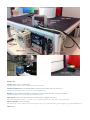
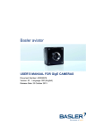
The demo system consists of a platform on which is
mounted a motor, encoder, spinning drum, light source,
laser-sensor and camera mount. There is a small “control
panel” on the front where the encoder & laser-sensor signals are wired into the camera’s input/output (I/O) ports.
Introduction
This document walks the reader through a sample line scan
setup using a runner Gigabit Ethernet camera. It is based
on instructions for setting up an in-house trade show demo
machine.
Mainly it explains how the runner’s specific features are
used in a basic line scan setup. From this, we hope to make
life easier during camera evaluations by pointing out some
hurdles, and offering some troubleshooting tips. For deeper
details on the settings and features used, we always recommend reviewing the user guide found on our website:
www.baslerweb.com/downloads/manuals/runner
What this document is not intended to do is to teach general line scan concepts or methodologies. These applications
can be very complex and precise, and require much more
training than this document could provide. So it is assumed
that the reader has some experience with line scan systems/
cameras. The reader who may benefit the most is probably
a machine vision integrator or OEM.
1
The runner is designed to emulate an area-scan camera to
make design-ins easier, especially from a software standpoint. The camera will expose a single-line CCD repeatedly while the object in view is moving, thus building up a
2D image within its memory. When the specified number
of lines is reached (either specified by the user, or limited
by the camera’s memory size), the runner will transmit the
image to the PC. Once there, the driver places the image
into a memory buffer created by the user’s software. This
buffer can then be accessed by the software for image processing, saving, etc.
Differences between this guide and the
Basler runner User Manual:
It might be important to note that this guide differs from the
use cases in the official manual.
The most significant difference is that the user manual
examples typically apply the
encoder signals (Line Start Triggers) to lines 1 & 2 while
placing the Frame Start Trigger on input 3.
The setup described in this document applies the
encoder signals to lines 2 & 3 while the Frame Start Trigger
is configured on input line 1.
Use Case
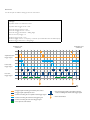
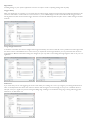
For this sample we will be setting up the use case below.
Settings:
Acqusition Mode = Continuous Frame
Acqusition Start Trigger Mode = Off
Frame Start Trigger Mode = ON
Frame Start Trigger Source = Line 1
Frame Start Trigger Activation = Falling Edge
Lines Per Frame (Height) = 3
Line Start Trigger Mode = On
Line Start Trigger Source = Frequency converter (from Shaft Encoder Module Output)
Line Start Trigger Activation = Rising Edge
Acquisition start
command
Acquisition start
command
Acquisition start
trigger signal
Frame start
trigger signal
Line start
trigger signal
Time
= Trigger signal internally generated by the camera
= Trigger signal applied by the user
= Camera is waiting for an acquisition start trigger signal
= Camera is waiting for a frame start trigger signal
= Camera is waiting for a line start trigger signal
= Line exposure and readout
= Line start trigger signal is ignored because the
camera is waiting for a frame start trigger signal
= Frame transmitted
Equipment
Camera: Basler runner ruL2048-30gm
http://www.baslerweb.com/products/runner.html?model=266
Camera I/O Cable: Basler Part #2000026691, Description: I/O Cable, HRS 12p, runner, 3 m
http://www.baslerweb.com/mv-accessories-13076.html?detail=32
Encoder: Stegman DRS61-ADK08192, Description: Incremental Encoder, 8192 counts/rev resolution.
http://www.stegmann.com/product/incremental/hollow.html
Laser Sensor: Keyence LV-21AP, Description: General Purpose Digital Laser Sensor
http://convertingsystemssupport.com/yahoo_site_admin/assets/docs/LV_H100_300_man.15391105.pdf
Motor Controller: Omron VS Mini J7
http://industrial.omron.co.uk/en/products/catalogue/motion_and_drives/frequency_inverters/general_purpose/j7/default.html
Motor: RGM
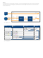
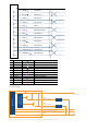
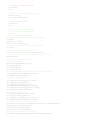
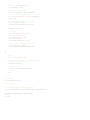
Wiring
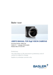
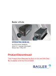
It is very important to wire the signals correctly. Figure 1 shows the overall triggering scheme. Figure 2 shows the actual wiring
setup. Note the grounds are tied together to reduce electronic noise issues. Figure 3 shows the color codes for the camera,
encoder, and laser sensor.
Frame Start
Trigger
Input
Line 1
Laser
Sensor
Phase A
Shaft
Phase B
Encoder
Input
Line 2
Phase A
Input
Input
Line 3
Phase B
Input
Shaft Encoder
Module
Module
Output
Frequency
Converter
Line Start
Trigger
Figure 1: Triggering Concept
Camera
Pin 2 Brown
Encoder
Laser-Sensor
(in 1+)
Black
Brown
Blue
Pin 9 Violet
(in 2+)
Pin 5 White
(A)
Pin 8 Black
(in 2-)
Pin 6 Brown
(A-)
Power/GND
(Control Output A)
(12-24 VDC)
(GND)
+ 12 VDC
GND
Pin 4 Yellow
(in 3+)
Pin 8 Pink
Pin 3 Green
(in 3-)
Pin 1 Black
(B-)
Pin 10 Blue
(GND)
GND
Pin 12 Red
(Supply Voltage)
+ 5 VDC
Pin 5 Gray
(GND)
Figure 2: Wiring Guide
(B)
GND
1
2
3
4
5
6
7
8
9
10
11
12
1
White
I/O Input 1-
2
Brown
I/O Input 1+
3
Green
I/O Input 3-
4
Yellow
I/O Input 3+
5
Gray
GND
10
Pink
Not Cponnected
6
Blue
I/O Output 1-
7
Red
I/O Output 1+
8
Black
I/O Input 2-
9
Violet
I/O Input 2+
11
Gray/Pink
I/O Output 2-
12
Red/Blue
I/O Output 2+
Black
Gray
Violet
Yellow
White
Brown
Orange
Pink
Signal line
Connected internally to US
Signal line
Signal line
Signal line
Signal line
Not connected
Signal line
Housing potential
Zero volt connected to the encoder
Connected internally to GND
Supply voltage 1)
B
Sense+
Z
Z
A
Ā
N.C.
B
Screen
GND
SenseUS
Violet
Green
Red
LV-21AP/51MP
Brown
Overcurrent
protection circuit
Main circuit
12 to 24 V DC
Black
(Control output A)
White
(Control output B)
Load
Load
Purple (Laser raclation interuption input)
Pink* (External tuning input)
Blue
0 V DC
Figure 3: I/O Cable Color codes for Camera, Encoder, and Laser Sensor, respectively.
Software Setup
Note that it is assumed the reader has successfully installed the pylon SDK and pylon Viewer, and has configured the IP address of
their camera correctly.
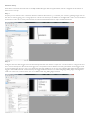
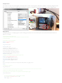
Step 1
Acquire your first frames. Once connected, click the Continuous Shot button ( ) to test that your camera is grabbing images. Turn on
the drum to assist by giving you a moving object. You can also use this step to set initial focus and light level. It is also recommended to
set the User Level to Guru at this point because some aforementioned features are only accessible at this level.
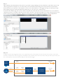
Step 2
Configure the Frame Start Trigger. Here we have already wired the Laser Sensor to Input Line 1 of the camera. To configure the camera to look to this input for the Frame Start Trigger, Go to Acquisition Controls feature branch in pylon Viewer, set the Trigger Mode
to On, and the Trigger Source to Line 1. You should see the image stabilize as we are now only collecting lines when the Frame Start
Trigger is Activated. “Activated” is determined by the Trigger Activation field. You can select Rising Edge, Falling Edge, Level High and
Level Low. In this case, our laser-sensor was more reliable when using Falling Edge activation.
Step 3
Make preliminary AOI adjustments. At this point it’s a good idea to begin adjusting your Area Of Interest, or AOI. This is used to only
collect image data from the place on your object that you are interested in. These settings are found in the AOI Controls feature
branch. Note that you may have to stop the grab to access some of these features, so we suggest zooming out, acquiring an image,
then stopping the grab to make these adjustments. Afterward, you can restart your continuous shot.
In this demo, the usable image does not start until around pixel column 820 and ends around 1250. Therefore, we set our Width to
1250-820=430, and our X Offset to 820. We may also wish to increase or decrease the Height of our image, otherwise known as the
number of Lines in the Frame. Note that Y Offset is not used, but the corresponding adjustment will be covered in Appendix A.
Step 4.a
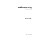
Configure the Line Start Trigger. This is the most complicated portion of the setup and can be done in various ways. For this demo
however, we will wire the encoder signals into the Shaft Encoder Module of the camera’s I/O block, then pass the output of this module to the Frequency Converter, and then finally into the Line Start Trigger.
Shaft
Phase A
Phase B
Encoder
Frame Start
Trigger
Input
Line 1
Laser
Sensor
Input
Line 2
Phase A
Input
Input
Line 3
Phase B
Input
Shaft Encoder
Module
Module
Output
Frequency
Converter
Line Start
Trigger
We begin by actually working backwards and assigning the Line Start Trigger’s Trigger Source to the Frequency Converter, and then
setting the Trigger Mode to On.
Note that at this point, grabbing images might result in a 0.0 frame rate. This is because the Frequency Converter is not yet linked to
the incoming encoder signals. This will be covered in the next steps.
Step 4.b
RS422 background. We are using an encoder which has two RS422 signal pairs, Phase A and Phase B. Because these are considered
Low-Voltage Differential Signals (LVDS), each phase consists of a + and – signal. The camera’s I/O block is designed to accept these
signal pairs as you’ll see from the wiring diagram. The A & B signals are also offset from each other so that one may determine the
direction of encoder movement by monitoring the state of both signals. The I/O block can also measure and report this to the use.
Note: The camera will also support RS644 and LVTLL signals
Phase A
Phase A
Phase B
Phase B
Tick
Tick Tick
Tick
Tick
Tick Tick
Tick
(Phase A leads Phase B, i.e., Phase B
(Phase B leads Phase A, i.e., Phase A
low at rising edge of Phase A)
low at rising edge of Phase B)
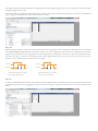
Step 4.c
Configure the Shaft Encoder Module. In pylon Viewer, select the Shaft Encoder Module feature branch, and assign the Phases to the
appropriate input lines from the triggering concept. You may also choose to monitor the direction, etc. but it is not required for this
demo.
Step 4.d
Configure the Frequency Converter. Select the Frequency Converter feature branch and assign it’s Input Source to the Shaft Encoder
Module Out. By doing this, you are taking the processed signal from the Shaft Encoder Module and using it to trigger the camera. At
this point you should see images grabbing in pylon Viewer.
In theory, it may be fine to skip this step and assign Shaft Encoder Module Out directly to Line Start Trigger. However, in this case we
are using an encoder with a resolution of 8192 pulses/revolution and a camera with a maximum line rate of about 30,000 lines per
second. So it is likely that we will begin to overtrigger the camera at speeds of only ~3.6 revolutions/second. If you are overtriggering
the camera, you will see this as an aspect ratio change in the image as your drum speed increases or decreases.
We overcome this limitation by using the Frequency Converter to scale the trigger signal. In this case, we wish to divide the incoming
signal by 10, such that the camera is only being triggered at a rate of 819.2 pulses/revolution. This means we can run our drum at over
360 rev/sec without overtriggering the camera.
At this point, initial setup is complete.You should now be able
to acquire frames at various drum speeds with no change in
aspect ratio or image position.
Appendix A
Tweaking settings to your specific application. Here are some tips & tricks to adjusting settings that may help.
Trigger Delay
After your initial setup is complete, you can revisit the Frame Start Trigger settings and adjust the Trigger Delay. This will instruct the
camera to wait either a certain number of microseconds or (more conveniently), a certain number of Line Start Triggers before
starting the frame, after the Frame Start Trigger has been received. This effectively takes the place of the Y Offset setting in the AOI
Controls.
Image Height Maximum
It should be noted that the maximum height of the image is limited by the camera’s internal memory. Pixel format and image width
are the two factors which influence how much memory is required for each image. Therefore you may notice that the maximum
image height is different when these settings are changed. So you may wish to save setting the image height for later on in your configuration.
Debouncer
If you notice that you are overtriggering the camera even when your settings are correct, you might try increasing the Debouncer
value on the input lines. This value is the minimum duration that the signal must remain high (or low) to be considered valid. For
example, some poor signals may ‘bounce’ during the falling edge, resulting in an inadvertent rising edge, causing a false trigger. The
Debouncer can filter these out.
Configuration Sets
It is always a good idea to save your settings to the camera to avoid losing them upon a power cycle. You can do this by using the
Configuration Sets feature branch. Stop the acquisition, select an unused User Set, and click Execute User Set Save. You can instruct
the camera to boot up with your settings by assigning your user set to the Default Startup Set.
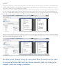
Spatial Correction (color models only)
If you are using a color camera, all of the above settings still apply. But initially you will probably end up with a non-spatially-corrected
image looking like the following. You can correct for this by adjusting the Spatial Correction feature under the Image Format Controls
branch.
Acquisition Start Trigger
For the demo setup described in this document, we’ve started each acquisition by using the Acquisition Start Command. This is a
software command sent to the camera to begin the acquisition. It is convenient to use because the pylon Viewer supplies simple GUI
buttons to do this. However, there may be a use case where the reader wishes to start their acquisition by some other means, for
example another hardware trigger. This is configurable in the Acquisition Controls feature branch. Note that a Software Trigger is very
similar to simply issuing the Acquisition Start Command in software, although there are subtle difference that may make one or the
other more convenient. Please see the user guide for more details.
Output Lines
The runner not only can receive signals on its inputs, but it can also output signals as well. This is useful for monitoring things like when
the camera is exposing a line to light (Exposure Active) or when it is ready for the next Frame Start Trigger (Frame Trigger Wait).
Appendix B
Complete pylon C++ sample program code for setting up the demo: You can use this in place of the standard AcquireContinuous
pylon C++ sample.
// AcquireContinuousRunnerDemo.cpp
// This code is to accompany the “How to setup the runner demo” document.
// mbreit 2011.06.28
// Include files to use the PYLON API
#include <pylon/PylonIncludes.h>
#include <stdlib.h>
using namespace Pylon;
#if defined( USE_1394 )
// Settings to use Basler 1394 cameras
#include <pylon/1394/Basler1394Camera.h>
typedef Pylon::CBasler1394Camera Camera_t;
using namespace Basler_IIDC1394CameraParams;
using namespace Basler_IIDC1394StreamParams;
#elif defined ( USE_GIGE )
// settings to use headers and libraries for Basler GigE cameras
#include <pylon/gige/BaslerGigECamera.h>
typedef Pylon::CBaslerGigECamera Camera_t;
using namespace Basler_GigECameraParams;
using namespace Basler_GigEStreamParams;
#else
#error Camera type is not specified. For example, define USE_GIGE for using GigE cameras
#endif
// Namespace for using cout
using namespace std;
// ************************************************************************************************
// Define some convinience functions, classes, and constants
// This function can be used to wait for user input at the end of the sample program.
void pressEnterToExit()
{
//comment the following two lines to disable wait on exit here
cerr << endl << “Press enter to exit.” << endl;
while( cin.get() != ‘\n’);
}
// CGrabBuffer class
class CGrabBuffer
{
public:
CGrabBuffer(const size_t ImageSize);
~CGrabBuffer();
uint8_t* GetBufferPointer(void) { return m_pBuffer; }
StreamBufferHandle GetBufferHandle(void) { return m_hBuffer; }
void SetBufferHandle(StreamBufferHandle hBuffer) { m_hBuffer = hBuffer; };
protected:
uint8_t *m_pBuffer;
StreamBufferHandle m_hBuffer;
};
// Constructor allocates the image buffer
CGrabBuffer::CGrabBuffer(const size_t ImageSize):
m_pBuffer(NULL)
{
m_pBuffer = new uint8_t[ ImageSize ];
if (NULL == m_pBuffer)
{
GenICam::GenericException e(“Not enough memory to allocate image buffer”, __FILE__, __LINE__);
throw e;
}
}
// Freeing the memory
CGrabBuffer::~CGrabBuffer()
{
if (NULL != m_pBuffer)
delete[ ]m_pBuffer;
}
// Buffers for grabbing
static const uint32_t c_nBuffers = 10;
// Number of images to be grabbed
static const uint32_t c_ImagesToGrab = 100;
// ************************************************************************************************
// The main program
int main(int argc, char* argv[ ])
{
// Automagically call PylonInitialize and PylonTerminate to ensure the pylon runtime system
// is initialized during the lifetime of this object
Pylon::PylonAutoInitTerm autoInitTerm;
try
{
// Get the transport layer factory
CTlFactory& TlFactory = CTlFactory::GetInstance();
// Create the transport layer object needed to enumerate or
// create a camera object of type Camera_t::DeviceClass()
ITransportLayer *pTl = TlFactory.CreateTl(Camera_t::DeviceClass());
// Exit application if the specific transport layer is not available
if (! pTl)
{
cerr << “Failed to create transport layer!” << endl;
pressEnterToExit();
return 1;
}
// Get all attached cameras and exit application if no camera is found
DeviceInfoList_t devices;
if (0 == pTl->EnumerateDevices(devices))
{
cerr << “No camera present!” << endl;
pressEnterToExit();
return 1;
}
// Create the camera object of the first available camera.
// The camera object is used to set and get all available
// camera features.
//Camera_t Camera(pTl->CreateDevice(devices[ 0 ]));
// Alternatively, one other way to open the camera is by a specific serial number :)
CDeviceInfo di;
di.SetSerialNumber( “20901529”);
Camera_t Camera(pTl->CreateDevice(di));
// Open the camera (the camera will take images and ‘shoot’ them to the PC)
Camera.Open();
// Get the first stream grabber object of the selected camera
Camera_t::StreamGrabber_t StreamGrabber(Camera.GetStreamGrabber(0));
// Open the stream grabber (pylon’s stream grabber will ‘grab’ the images shot from the camera)
StreamGrabber.Open();
// Configure the camera according to the setup guide
// Set the image format and AOI
Camera.PixelFormat.SetValue(PixelFormat_Mono8);
Camera.OffsetX.SetValue(820);
Camera.Width.SetValue(430);
Camera.Height.SetValue(500);
// Configure the AcquisitionStart Trigger (AcquisitionStart is controlled by software in this case)
Camera.TriggerSelector.SetValue(TriggerSelector_AcquisitionStart);
Camera.TriggerMode.SetValue(TriggerMode_Off);
// Configure the FrameStart Trigger (Laser-sensor)
Camera.TriggerSelector.SetValue(TriggerSelector_FrameStart);
Camera.TriggerMode.SetValue(TriggerMode_On);
Camera.TriggerSource.SetValue(TriggerSource_Line1 );
Camera.TriggerActivation.SetValue(TriggerActivation_FallingEdge);
Camera.TriggerDelaySource.SetValue(TriggerDelaySource_LineTrigger);
Camera.TriggerDelayLineTriggerCount.SetValue(150);
// Configure the LineStart Trigger (Encoder)
Camera.TriggerSelector.SetValue(TriggerSelector_LineStart);
Camera.TriggerMode.SetValue(TriggerMode_On);
Camera.TriggerSource.SetValue(TriggerSource_FrequencyConverter);
Camera.TriggerActivation.SetValue(TriggerActivation_RisingEdge);
// Configure the FrequencyConverter for the LineStart Trigger
Camera.FrequencyConverterInputSource.SetValue(FrequencyConverterInputSource_ShaftEncoderModuleOut);
Camera.FrequencyConverterPreDivider.SetValue(10);
Camera.FrequencyConverterMultiplier.SetValue(1);
Camera.FrequencyConverterPostDivider.SetValue(1);
// Configure the ShaftEncoderModule for the LineStart Trigger
Camera.ShaftEncoderModuleLineSelector.SetValue(ShaftEncoderModuleLineSelector_PhaseA);
Camera.ShaftEncoderModuleLineSource.SetValue(ShaftEncoderModuleLineSource_Line2);
Camera.ShaftEncoderModuleLineSelector.SetValue(ShaftEncoderModuleLineSelector_PhaseB);
Camera.ShaftEncoderModuleLineSource.SetValue(ShaftEncoderModuleLineSource_Line3);
// Set continuous acquisition mode
Camera.AcquisitionMode.SetValue(AcquisitionMode_Continuous);
// Set exposure settings
Camera.ExposureMode.SetValue(ExposureMode_Timed);
Camera.ExposureTimeRaw.SetValue(32);
// Configure the buffer queue and the stream grabber
// Use the payload size to determine the total size of the incoming image
const size_t ImageSize = (size_t)(Camera.PayloadSize.GetValue());
// We won’t use image buffers greater than ImageSize
StreamGrabber.MaxBufferSize.SetValue(ImageSize);
// We won’t queue more than c_nBuffers image buffers at a time
StreamGrabber.MaxNumBuffer.SetValue(c_nBuffers);
// Allocate all resources for grabbing. Critical parameters like image
// size now must not be changed until FinishGrab() is called.
StreamGrabber.PrepareGrab();
// Buffers used for grabbing must be registered at the stream grabber.
// The registration returns a handle to be used for queuing the buffer.
// Note: It is good practice to always use more than one buffer in your queue.
// This ensures that if the software is too slow to process the rate of incoming images
// the driver will not let incoming images back up and be overwritten before being processed.
std::vector<CGrabBuffer*> BufferList;
for (uint32_t i = 0; i < c_nBuffers; ++i)
{
CGrabBuffer *pGrabBuffer = new CGrabBuffer(ImageSize);
pGrabBuffer->SetBufferHandle(StreamGrabber.RegisterBuffer(
pGrabBuffer->GetBufferPointer(), ImageSize));
// Put the grab buffer object into the buffer list
BufferList.push_back(pGrabBuffer);
}
for (std::vector<CGrabBuffer*>::const_iterator x = BufferList.begin(); x != BufferList.end(); ++x)
{
// Put buffer into the grab queue for grabbing
StreamGrabber.QueueBuffer((*x)->GetBufferHandle(), NULL);
}
// Start the image acquisition
// Execute AcquisitionStart in Software - Camera is now waiting for triggers to begin shooting images
Camera.AcquisitionStart.Execute();
// Launch a software loop to monitor the StreamGrabber.
for (int n = 0; n < c_ImagesToGrab; n++)
{
// Wait for the StreamGrabber to tell us about the image it has received from the camera.
if (StreamGrabber.GetWaitObject().Wait(INFINITE))
{
// Get the grab result from the grabber’s result queue
GrabResult Result;
StreamGrabber.RetrieveResult(Result);
if (Grabbed == Result.Status())
{
// Grabbing was successful, process image
cout << “Image #” << n << “ acquired!” << endl;
cout << “Size: “ << Result.GetSizeX() << “ x “
<< Result.GetSizeY() << endl;
// Get the pointer to the image buffer
const uint8_t *pImageBuffer = (uint8_t *) Result.Buffer();
// do something with the image buffer (ie: copy it, save it, access data)
cout << “Gray value of first pixel: “ << (uint32_t) pImageBuffer[0]
<< endl << endl;
// Put the buffer back into the queue so it can be reused.
if (n < c_ImagesToGrab - c_nBuffers)
StreamGrabber.QueueBuffer(Result.Handle(), NULL);
}
else if (Failed == Result.Status())
{
// Error handling
cerr << “No image acquired!” << endl;
cerr << “Error code : 0x” << hex
<< Result.GetErrorCode() << endl;
cerr << “Error description : “
<< Result.GetErrorDescription() << endl;
// Reuse the buffer for grabbing the next image
if (n < c_ImagesToGrab - c_nBuffers)
StreamGrabber.QueueBuffer(Result.Handle(), NULL);
}
}
else
{
// Timeout
cerr << “Timeout occurred!” << endl;
// Get the pending buffer back (You are not allowed to deregister
// buffers when they are still queued)
StreamGrabber.CancelGrab();
// Get all buffers back
for (GrabResult r; StreamGrabber.RetrieveResult(r););
// Cancel loop
break;
}
}
// Stop acquisition
Camera.AcquisitionStop.Execute();
// Do some Clean up
// You must deregister the buffers before freeing the memory
for (std::vector<CGrabBuffer*>::iterator it = BufferList.begin(); it != BufferList.end(); it++)
{
StreamGrabber.DeregisterBuffer((*it)->GetBufferHandle());
delete *it;
*it = NULL;
}
// Free all resources used for grabbing
StreamGrabber.FinishGrab();
// Close stream grabber
StreamGrabber.Close();
// Close camera
Camera.Close();
}
catch (GenICam::GenericException &e)
{
// Error handling
cerr << “An exception occurred!” << endl
<< e.GetDescription() << endl;
pressEnterToExit();
return 1;
}
// Quit the application
pressEnterToExit();}
return 0; Basler AG
Germany, Headquarters
Tel.
+49 4102 463 500
Fax
+49 4102 463 599
[email protected]
www.baslerweb.com
02/12
USA
Tel.
+1 610 280 0171
Fax
+1 610 280 7608
[email protected]
Asia
Tel.
+65 6425 0472
Fax
+65 6425 0473
[email protected]
17