1
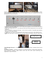
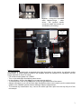
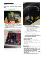
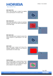
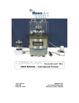
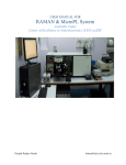
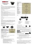
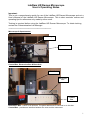
LabRam HR Raman Microscope
User’s Operating Notes
Important:
This is not a comprehensive guide for use of the LabRam HR Raman Microscope and not a
User’s Manual of the LabRam HR Raman Microscope. This is short reminder notices and
operating tips for references only made by other users.
Training is required before using the LabRam HR Raman Microscope. To obtain training,
contact the Characterisation Lab Manager.
~~~~~~~~~~~~~~~~~~~~~~~~~~~~~~~~~~~~~~~~~~~~
Microscope & Spectrometer
Microscope
Spectrometer
Control Box, Electronics Box & Base Unit
Base Unit
Electronics
Box
Control
Box
Electronics Box - Leave on at all times. The piezo attachment is switched on to this box.
Control Box - provides an interface between the user and the instrument.
1
Front and rear view of Control Box. If it is switched off you can turn it on at the back of the box. (Note:
leave it switched on all the time). When the power supply is turned on a red light will be lit on top
left hand side of the front of the box.
down
up
down
up
down
up
• Laser OFF: Turn key to switch laser on & off. When laser switched on the two small LED Laser &
Interlock indicators will glow red.
• DIODE ON: Always leave OFF. If you leave this ON, the CCD will saturate due to too much light
getting to it.
• SHUTTER MICRO: If using the microscope – turn it to the ‘up’ position. If using fibre optic entrance
then turn it to the ‘down’ position.
• CAMERA ON: This switch controls the power for the camera in microscope. Leave ON all the time.
• LASER ON: Shuts laser to come down the microscope towards the sample. Leave OFF when not in
use.
Liquid Nitrogen
Reservoir
Symphony
Controller
Liquid Nitrogen Reservoir - is essential to keep system cool at all times, it should be filled 3 times
weekly.
Symphony Controller – provides co-ordination of all detector functions, including power distribution,
array temperature regulation, digital readout control and CCD video output conditioning and
digitalization of pixel information.
2
Microscope light source
Joystick - moves the motorised
table LabspecTango – table
driver. The joystick handle
moves the table and moves up
and down by its rotating.
Always
out
Splitter
Beam
Splitter
Image Acquisition
The LabRAM is equipped with a standard white light illumination of the sample, by reflection and/or
transmission. A colour camera linked to the software allows the sample to be visualised, and the
image captured on the PC & saved.
- Put camera beam splitter into “VIDEO”
- Turn on the white light illumination power source
- In the software, click on the video icon to start camera read-out.
- To freeze picture, click on the stop icon on the top right hand side of the screen.
- Always remember to turn off the white light illumination power source and to put the camera beam
splitter to the ‘RAMAN’ position before starting a Raman measurement.
- To illuminate by transmission only, remove the white light fibre optic from the top left port of the
microscope.
3
Using green and blue laser
Info: laser beam spot at 100x lens is about
0.6 um.
Switch on the Argon Power Supply under the
table:
the top knob
- switch on the main switch “AC power”,
- turn key clockwise 90°
- switch the switch on the PCB board from
‘standby’ to ‘on’, the LED “standby will off
- change two filters (marked 1 in the picture)
under the cover at the top of spectrometer for
457 or 514 nm wavelength.
- check that the mirror (marked 2 in the picture)
is pulled up
1
1
2
- click on ‘LabSpec 5’ icon on PC:
You will see in the top the following icons:
Camera – to take video image
Blue wheel – take fast measurements
Pink pig – take measurements
Ridge – take the map
Greed – set map parameters
in the “acquisition” group of windows at the
bottom:
Top window: Refresh time
Collect time: ~ 5 sec, usually
Scan number: to take an average
The centre of the measurements window is
set in the window “spectrometer”
-
choose the wavelength
set hole ~ 100 um
filter to reduce the power, usually 10%
set 2400 grading, this parameter affects on
the noise and intensity
- set proper lens which is chosen in the
microscope
- close the cover
- adjust the laser to maximum brightness using
the top knob behind the setup
Zero Calibration
- check beam splitter switch set to “video”
(“beam splitter down” – in the manual)
- turn on white light box
- change units to nm: Options –> Units –> nm
- click arrow left in the window “spectrometer”
to send spectrometer to zero position
- wait until you see 0(>I<) in the window
“spectrometer”
- click the blue wheel to take the spectrum
4
- press Stop when spectrum is taken
- zoom in on peak using magnification button
(looks like magnifying glass)
- go to Setup –> Instrument Calibration
- wright on the paper values shown in the two
bottom windows
- if the peak position not at zero, adjust Zero
Parameter in small amounts (up to 5)
- press Apply
- when peak at zero, resend spectrometer to
zero 0(>I<) again and retake spectrum
Raman Calibration
- change units to cm-1 Options –> Units –> cm-1
- send spectrometer to 520.7 cm-1 position
- put the Si calibration sample on a glass slide
under the microscope objective
- click Camera icon to open the video window
and focus on silicon calibration sample (x100
objective)
- click Stop
- turn off the white light, then switch the beam
splitter to ‘Raman’
- move up the “laser on” switch on the Control
Box
- click the blue wheel to take at 25% 300 um
hole
- press Stop
- magnify peak as before
- go to Setup –> Instrument Calibration and
adjust “KOEFF” value by small amounts until
peak is in correct position, press Apply
- retake spectrum
- check laser power (approx 5.0 mW), modify
filter accordingly
To take spectra
- go to “extended Range” and set Multiwindows,
- enter bottom and top value for the required
diapason
To switch off the blue/green laser
Switch off the Argon Power Supply under the
table:
- switch the switch on the PCB board from ‘on’
to ‘standby’, the LED “standby will
on
- turn the key counter clockwise 90°
- wait 20 min
- switch off the main switch “AC power”,
Using UV laser
- put the warning sign on the door
- wear UV protectin googles
Behind the setup:
- switch on the red switch
- turn on the key
- touch the tubes to check cooling
From the top:
- move down the mirror
- set the filter 364 nm at the output
- use the 60x lens
- calibrate and take spectra as for visible laser
5