1
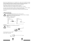
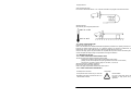
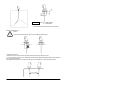
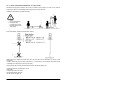
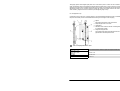
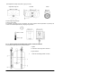
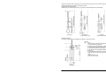
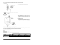
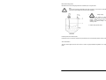
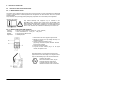
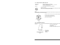
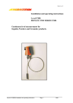
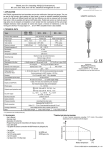
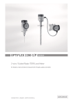
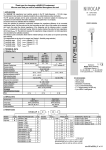
INSTALLATION
and
PROGRAMMING MANUAL
Manufacturer:
NIVELCO Control Co.
H-1043 Budapest, Dugonics u. 11.
Tel.: (36-1)-369-7575 Fax: (36-1)-369-8585
E-mail:[email protected] http://www.nivelco.com
DEVICE DESCRIPTION AND RANGE OF APPLICATIONS
The MicroTREK 2-wire level gauge uses the Time Domain Reflectometry (TDR) measuring principle and two-wire
technology for level measurement. It is designed solely for measuring the distance, level, volume and ullage of liquids,
pastes, slurries and powder products. It can continue to measure the level or distance and total volume in applications with
two products.
The level measurement data can be displayed and the gauge configured using either a HART Handheld Communicator
console (HHC) or a PC work station equipped with PCSTAR2 software supplied as standard with the gauge.
Principal gauge components
with highwith raising
MicroTREK 2-wire housing and probes (non-Ex and Ex versions)
temperature
converter option
option
1
2
3
4
5
6
7
8
9
10
11
12
13
14
15
Nameplate (see next page for details)
Cable entry (output and power supply) to wiring compartment
Equipotential bonding system connection (Ex – see section 2.1.4)
Flange (process connection onto tank or other suitable mounting)
Single cable probe
Counterweight (with threaded hole in base for anchoring)
Twin cable probe
Spacer
Chuck / ring (for single cable probes)
Turnbuckle (for twin or single cable probes)
Threaded process connection (e.g. 1” G, 1” NPT, …)
Coaxial probe
Extension tube for high temperature applications
Single rod probe
Raising converter: coaxial tube under the process connection (i.e. an inactive length of the probe) for
installations with long nozzles or concrete roofs – for single rod and single cable probe versions only
MicroTREK 2-wire
Standard nameplate
*eg. ABM-110-1. The “type code” gives the options chosen for this unit and is defined in the MicroTREK 2-wire Data Sheet.
This document is available from your local NIVELCO Sales office or on the “Download” site on NIVELCO’s website
http://www.nivelco.com/.
Items included with supply:
The scope of supply encompasses:
Signal converter with probe in the version ordered. The version is stated on the nameplate.
PCSTAR 2 computer software for data display and gauge configuration
Documentation supplied:
Installation & programming manual:
Installation, connection, start-up and safety advice.
Detailed user manual and reference book, including how to configure meter parameters available in the user menu and
how to perform basic maintenance.
Supplementary Installation and Operating Instructions MicroTREK 2-wire
KEMA 03ATEX1565X
Supplementary instructions covering devices to be installed and used in hazardous areas.
This document is only supplied with specially approved instruments. This document is available from your local NIVELCO
Sales office or on the “Download” site on NIVELCO’s website http://www.nivelco.com/.
Product liability and warranty:
The MicroTREK 2-wire TDR level gauge is designed for measuring the distance, level, and volume of liquids, pastes,
slurries and powders. It may equally measure level, distance, total volume and ullage in applications where two or more
products are present.
Special codes and regulations apply to its use in hazardous areas : please refer to the MicroTREK 2-wire KEMA
03ATEX1565X Supplementary Installation and Operating Instructions for further information. This document is available
from your local NIVELCO Sales office or on the “Download” site on NIVELCO’s website http://www.nivelco.com/.
Responsibility as to suitability and intended use of these level gauges rests solely with the user.
Improper installation and operation of our level gauges may lead to loss of warranty.
In addition, the "General conditions of sale", forming the basis of the purchasing contract, are applicable.
If you need to return measuring instruments to NIVELCO, please note the information given in Appendix C. NIVELCO
regrets that they cannot repair or check your device unless it is accompanied by the completed form.
The level gauge does not form part of an overfill protection system (as defined for example in WHG: German water
resources act).
1. MECHANICAL INSTALLATION
1.1 HANDLING AND STORAGE
To carry: the device will weigh between approx. 3 kg or 7 lb and 12 kg or 25 lb.
Carry using both hands to lift the device carefully by the converter housing. If necessary, use lifting gear.
No attempt should be made to lift the instrument by its probe.
Caution:
The probe is a critical gauge component.
Do not damage– Handle with care!!!
Avoiding blows
When handling the MicroTREK 2-wire, avoid hard blows, jolts, impacts, etc.
Caution:
Fragile electronics
Avoid bending (single rod and coaxial probes)
Support the probe to avoid bending.
Support probe here
Avoid cable kinks and fraying
Do not coil the cable less than 400 mm or 16 “ in diameter. Cable kinks or fraying will cause measurement errors.
Storage temperature
Store within the given storage temperature limits.
1.2 INSTALLATION RESTRICTIONS
Hazardous-duty systems (Ex, FM,…)
Refer to the MicroTREK 2-wire KEMA 03ATEX1565X Supplementary Installation and Operating Instructions for further
information on installing gauges approved for use in hazardous locations. This document is available from your local
NIVELCO Sales office or on the “Download” page on NIVELCO’s website http://www.nivelco.com/.
Check that the flange, gasket and probe materials are compatible with the product. Read the information given on the
converter nameplate, the flange markings and specifications in the approval certificates.
1.3 MOUNTING ON THE TANK
1.3.1 INSTALLATION INSTRUCTIONS: GENERAL NOTES
The fitter should give some thought to tank fittings and tank shape.
nozzle position in relation to the tank walls and other objects inside the tanks
(Warning : this free area will depend on the probe type selected: refer to later on in this section)
type of tank roof, i.e. floating, concrete, integral, etc; and base, i.e. conical, etc.
Whenever working on an installation, remember to:
Disconnect the power supply before starting work.
However, the gauge may be installed when the tank contains product.
1.3.2 INSTALLATION INSTRUCTIONS: NOZZLE
Threaded process connections
The simplest and most economic way is to mount the
MicroTREK 2-wire directly on the tank with the 1”G or
1”NPT threaded connection.
Nozzle height
Recommendation
Do not fit a nozzle longer than its diameter,
especially for single probes and powder
applications
h ≤ Ød
, where h = nozzle height and
d = nozzle diameter
Contact NIVELCO if this relationship cannot be respected.
Nozzles extending into tank
Caution:
Do not use nozzles that extend into the tank. This will disturb the emitted pulse.
Installation of two devices
If two devices are to be used on the same tank, these should be mounted at a distance of at least
2 m or 6.5 ft away from each other. If not, interferences from the electromagnetic (EM) fields generated by both instruments
may cause measurement errors.
Not applicable to coaxial probes - the outer shell of the probe contains the EM field: no minimum distance required.
Process connection
For the gauge to make accurate measurements:
the tank process connection must be level.
ensure a good fit with the gauge process connection
the tank roof should not deform under the weight of the gauge
Process connection and entry pipe
Caution:
Do not put the nozzle close to the entry pipe. Pouring the product directly onto the probe will give false
readings. Install deflector plate if impossible to distance gauge from entry pipe.
Stilling wells
Tanks with floating roofs for petrochemical applications: Use a stilling well.
1 Stilling well
2 Tank
3 Floating roof
4 Product (petroleum applications)
5 Well fixed to tank base (no roof deformation)
6 Sediment
1.3.3
INSTALLATION INSTRUCTIONS: GAUGE - ALL APPLICATIONS
MicroTREK 2-wire gauges are designed to be mounted on a suitable process connection on a tank or sump. Install the
gauge using two people to avoid damaging the probe. Support the housing and the probe.
Installation of single and twin cable probe level meters
1 Caution :
Do not over-bend probe!
2 Inserting the probe:
hold more than one metre
above the opening to avoid
cable bending.
Probes: entanglement, straightness and tank bottom clearance
Cable probes must be straight once inserted into the tank. They must also be far from other objects (e.g. mixers) to avoid
entanglement.
In order to maintain the gauge’s operating characteristics, it is recommended to avoid touching the tank bottom with the
counterweights (for cable probes) or probe end (other types).
Objects (discontinuities) inside the tank that influence the probe’s EM (electromagnetic) field
Install the gauge far from protruding objects such as:
heating tubes,
sudden changes in tank cross-section,
tank wall reinforcements and beams,
weld lines and dip-stick pipes, etc...
TDR gauges generate electromagnetic (EM) fields when a measurement pulse is emitted. This field is affected by any
nearby discontinuities and these will weaken and potentially block the emitted pulse. A minimum distance is recommended
depending on the probe type to be installed. See the table on the next page for recommended free space dimensions.
Alternatively, the fitter may use a reference chamber or stilling well. However, the chamber walls must be smooth (i.e. no
visible weld lines), straight and vertical to maintain the pulse strength and gauge accuracy.
For clean applications only :
Coaxial probes may be used close to or touching objects or walls as the EM field generated by the probe is contained within
the probe’s outer sheath (refer also to the EM field sizes/free area given in the figures on the next page).
1 Agitator
2 Support beam perpendicular to the pulse direction
3 Abrupt changes in tank cross section
4 Heating tubes
5 Alternative solution: reference chamber –electromagnetic field
is contained within chamber
6 Gauge electromagnetic field :
Any intruding metallic object will be detected in this zone if
perpendicular to the emitted pulse direction.
= Do not fit the gauge near to these objects.
Probe Type
Single cable ∅ 4 mm,
Single cable ∅ 8 mm,
Single rod
Twin cable
Coaxial
Recommended minimum distance of probe from objects inside the tank
300 mm or 12”
100 mm or 4”
0 mm or 0”
Electromagnetic field shape around probe, by type (not to scale)
Single cables, single rod
Twin cable
Coaxial
No beam angle for any probe type.
Avoid direct solar radiation.
Fit a sunshade on the gauge for open-air installations: this is either supplied on demand by NIVELCO or provided by the
customer. The ambient temperature limits of the gauge are given below.
1.3.4 SPECIFIC INSTALLATION INSTRUCTIONS: GAUGE - LIQUID APPLICATIONS
Probe bending in agitated products: recommended solutions
1 Agitator
2 Turnbuckle for anchoring probe to tank bottom
3 Bypass chamber
4
Probe and counterweight (centred on request)
Mounting on a reference vessel or still well is ideal. To ensure that the probe does not come into contact with the tank wall,
the probe should be fixed to the bottom of the chamber or centred.
Fastening the probe to the tank bottom
Flexible probes can be fastened with a chuck (ring), turnbuckle or similar fastening device to the tank bottom:
Chuck (ring)
Turnbuckle
for Ø8 mm cable probes
Turnbuckle
for Ø4 mm cable probes
Shortening cable probes
If required, the cable probe can be shortened, but this applies only when used in liquids.
Procedure
Step
Action
1 Detach socket set screw M6x10 (ISO 4026) with 5
mm Allen (hexagon) key (ISO 2936).
2 Pull cable (2) out of counterweight (3) and shorten
to required length using cable cutters to prevent
the cable wires and strands from splaying out.
3 Insert cable back into counterweight and tighten
down screws
4 Change configuration parameters to new probe
length; the reference point is the top edge of the
weight
(user menu function 1.1.6)
Dimensions in mm (inches).
1.3.5
SPECIFIC INSTALLATION INSTRUCTIONS: GAUGE - SOLID APPLICATIONS
False readings:
1 Do not let probe touch the side of the nozzle
Conical silo nozzles, false readings and traction on the cable probes
Caution
2 High traction forces :
We recommend that the probe should not be
anchored to avoid excessive traction loads on the
cable.
3 Bending and traction:
Position the connection on the roof at ½ radius of the
tank and with minimum nozzle height. This will avoid
damage due to bending and traction during emptying.
Traction forces during emptying cycles for powder applications
Traction load is dependent upon the height and shape of the tank, product particle size & density, and the rate at which the
tank is emptied. The table below gives the load up to which cable probes will hold.
Cable maximum design load, traction
Probe
Maximum Load
Single cable Ø8 mm or Ø0.3”
3.5 T or 7700 lb
Traction on cable according to product (approximate value in metric tons)
Probe Length / m (ft)
Probe used
Material
10 (33)
20 (65.5)
Single cable Ø8mm or
Cement
1.0 T or 2200 lb
2.0 T or 4410 lb
Ø0.3”
Fly ash
0.5 T or 1100 lb
1.0 T or 2200 lb
30 (98.5)
3.0 T or 6620 lb
1.5 T or 3300 lb
Electrostatic discharge (E.S.D.)
MicroTREK 2-wire non-Ex and Ex gauge electronics are shielded up to 4 kV against E.S.D..
Note:
E.S.D. cannot be solved by MicroTREK 2-wire E.S.D. protection. It is the customer’s responsibility to
avoid E.S.D. by grounding the tank, product and probe installation.
1
Danger of injury
The probe may receive an electrostatic
discharge during operation; earth the probe by
pushing it against tank wall with a suitably
isolated tool just before touching it to avoid
receiving a shock.
2 Earth the entry pipe and product.
Product deposits on the nozzle and probe
Product build-up can occur under the nozzle: this may weaken the pulse. Avoid cavities that permit the build-up of deposits.
Tank roof deformation
Tank roofs should support loads of at least 3.5 tonnes or 7700 lb for gauge installations using Ø8mm or 0.3” single cable
probes.
2 ELECTRICAL CONNECTIONS
2.1 ELECTRICAL INSTALLATION INSTRUCTIONS
2.1.1 WIRING GENERAL NOTES
Connection to power is effected at the plug connector in the signal converter. Two wiring compartments are available: DIN
connector or M16 terminal box. Observe applicable rules and regulations for cable connection: VDE 165 or equivalent
national regulations.
Always disconnect from power supply before opening wiring compartment. This is not mandatory for Exi applications.
Hazardous-duty systems
Only certified intrinsically safe equipment may be connected to the
MicroTREK 2-wire in hazardous areas. Please refer to the MicroTREK 2-wire
KEMA 03ATEX1565X Supplementary Installation and Operating Instructions for
further information. This document is available from your local NIVELCO Sales
office or on the “Download” site on NIVELCO’s website http:// www.nivelco.com/.
2.1.2
WIRING CONNECTIONS: DIN CONNECTOR
Terminals:
3 poles and 1 x ground. Wire cross-section: max. 1.5 mm² (AWG 16)
Cable entry:
1 x PG11, cable diameter: 8 … 10 mm (0.31 … 0.39”), IP 65
Shielding:
do not connect to the DIN connector.
Signal cable:
no shielding required
1 Detach screw P and remove plug from signal converter.
2 Separate part N from part R by inserting the flat tip of a
screwdriver into gap F.
3 Connect current loop to terminals 1 and 2
(any polarity). Use ferrules to protect cable ends. Terminals
3 and E are not connected.
4 Fit parts N and R together again.
5 Fit gasket, re-insert connector plug R on the signal
converter, and replace screw P.
Grounding terminal E is not connected to the housing of the
signal converter or to the device flange. To avoid ground current
loops, the cable shielding may not be connected at both ends.
Hazardous-duty systems
When used in hazardous areas, only one
intrinsically safe power supply may be
connected to terminals 1 and 2. Ground
terminal E and terminal 3 are not connected.
2.1.3
WIRING CONNECTIONS: M16 TERMINAL BOX
Power terminals:
Cable entry:
Shielding:
Wire cross-section: max. 1.5 mm² (AWG 16)
1 x M16 x 1.5, cable diameter: 3.5 … 8 mm (0.14 … 0.31”), IP 65
for USA: ½” NPT conduit connection
Do not connect shielding to the terminal compartment.
Hazardous-duty systems
When used in hazardous areas, only one intrinsically safe power supply may be connected to
terminals 1 and 2. Ground terminal E is not connected.
Caution
Ground terminal, E, is not connected to the signal converter housing or to the device flange. To avoid ground current loops,
the cable shielding may not be connected at both ends.
1
Detach the 4 screws T, and remove cover from terminal compartment.
2
Connect the cable ends, fitted with ferrules,
to the power terminal U (not polarity sensitive).
3
Shut the terminal compartment.
2.1.4 ’EX’ EQUALIZING CONDUCTOR
Refer to the MicroTREK 2-wire KEMA 03ATEX1565X Supplementary Installation and Operating Instructions for further
information.
Terminal for equipotential bonding
U-clamp terminal,
max. conductor cross-section:
4 mm²/6.2 • 10-3 sq.in. on ’neck’ of signal converter
2.2 POWER SUPPLY
2.2.1 NON-HAZARDOUS-DUTY VERSION
MicroTREK 2-wire
Power supply
Rated voltage
Max. voltage
(Uinput):
Min. voltage
(Uinput):
24 V DC
35 V DC
’Ex’ = 28 V DC
dependent on
load impedance, see
graph below
A supply voltage above 35 V DC can cause irreparable damage to the signal converter.
Also, power supply voltages above the specified max. values and below the specified min. values
can lead to faulty measurements or to a device reset.
Load impedance RA
Loop resistance, Rloop
Min. RA
Max. RA
RHART resistance for HART® communication
RHART + Rcable + Rammeter
0
750
250
(recommended)
Line A = minimum voltage at the MicroTREK 2-wire terminals
Line B = minimum supply voltage (for voltage drop caused by a 250 Ohm loop resistance)
Example for calculating the power supply:
The voltage drop is tested at 22 mA.
U power min. 22 = 22 mA x load impedance + Uinput min. 22
U power min. 22 = 22 mA x 250 Ω + 10 V = 5.5 V + 10 V = 15.5 V
In order to cover the whole current range, the voltage drop must also be tested at 4 mA.
By analogy, the following applies:
U power min. 4 = 4 mA x load impedance + Uinput min. 4
U power min. 4 = 4 mA x 250 Ω + 18 V = 1 V + 18 V = 19 V
At a load impedance of 250 Ω a power supply voltage of 19 V is sufficient to energize the current device range of
4 to 20 mA.
2.2.2 HAZARDOUS-DUTY VERSION
The certified device may only be used with other ’Ex’ certified equipment. The minimum electrical safety data indicated on
the nameplate must be observed. To ensure proper operation, the minimum parameters specified above in section 5.4.1 for
the supply power must be observed to ensure that a given 4 to 20 mA converter is adequate for use with the
MicroTREK 2-wire. For more information refer to the MicroTREK 2-wire KEMA 03ATEX1565X Supplementary Installation
and Operating Instructions for further information. This document is available from the “Download” page on NIVELCO’s
website http:// www.nivelco.com/.
In addition, the connected equipment
must be HART®-compatible so that it
MicroTREK 2-wire
can be operated with the
communication software or the
HART® communicator.
An ’Ex’ repeater power supply unit
must be used. For calculation of the
supply voltage the same applies as for
the non-’Ex’ version.
2.3 ELECTRICAL OUTPUT
2.3.1 NETWORK OPTIONS
The output is available in 2 versions:
Current output HART®,
Current output Ex-ia HART®
passive, HART® protocol
intrinsically safe; passive, HART® protocol
All versions with HART® protocol can be operated with the PC-STAR 2 program.
mcd AB
Gasverksvägen 1
SE-611 35 Nyköping
Tel: + 46 (0) 155 - 22 27 90
Fax: + 46 (0) 155 - 22 27 99
E-post: [email protected]
www.mcd.se
Org nr: 556215-2180
Vat nr: SE556215218001
Miljö & cisterninstruMent för drivMedelsAnläggningAr