1
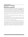
Expressionist
MIDI-CV Converter
User's Manual
Revision 1.13
August 1, 2004
Encore Electronics 611 Laird Ln. Lafayette, CA 94549 www.encoreelectronics.com
TABLE
OF
CONTENTS
INTRODUCTION ....................................................................................................................................................... 3
UNPACKING AND INSTALLATION ..................................................................................................................... 4
QUICK START ........................................................................................................................................................... 5
FRONT PANEL .......................................................................................................................................................... 6
PROGRAMMING ...................................................................................................................................................... 7
SETUP PAGE .............................................................................................................................................................. 8
CHANNEL AND MODE SELECTION.................................................................................................................... 8
NOTE RANGE ............................................................................................................................................................ 9
TRANSPOSE AND PITCHBEND............................................................................................................................. 9
PORTAMENTO........................................................................................................................................................ 10
TUNING..................................................................................................................................................................... 11
AUXILIARY MODE ................................................................................................................................................ 12
TRIGGER .................................................................................................................................................................. 12
MODULATIONS ...................................................................................................................................................... 13
LFO MIX ................................................................................................................................................................... 13
LFO SETUP............................................................................................................................................................... 14
LFO MODULATION ............................................................................................................................................... 15
LFO CHANNELS...................................................................................................................................................... 15
POLYPHONIC GROUPS ........................................................................................................................................ 16
POLYPHONIC MODES .......................................................................................................................................... 17
GLOBAL MIDI AND CONTRAST ........................................................................................................................ 18
DIN SYNC.................................................................................................................................................................. 19
SAVING SETUPS ..................................................................................................................................................... 19
SYSTEM EXCLUSIVE ............................................................................................................................................ 20
MIDI IMPLEMENTATION .................................................................................................................................... 21
SETUP DATA............................................................................................................................................................ 22
SYSEX MESSAGES ................................................................................................................................................. 24
2
Introduction
Thank you for purchasing the Expressionist ®!
The Expressionist is the most capable MIDI to control voltage converter on the market. It supports
both types of control voltage used by vintage synthesizers. The high resolution D/A converter gives
you precise control of your equipment, without the zipper noise that you might have experienced in
other products. Also, there are no trimmer pots to adjust! This means that you never have to find a
small screwdriver to get your favorite synthesizer to sound right.
The Expressionist offers eight complete channels of control voltage. A channel consists of a ¼"
control voltage jack, and a ¼" gate jack. Each channel has available: pitch bend, four modulations,
four LFOs, six octave transpose, two types of portamento, voltage offset and tracking, note range,
trigger polarity and trigger mode. The trigger jacks are programmable, so they can be used as a
Positive Gate for triggering synthesizers from manufacturers such as Roland®, ARP®, and
Oberheim® (among others), or as S-Triggers for Moog® synthesizers.
The Expressionist also features four global LFOs. They can each be modulated by different sources.
These can then be mixed in various ways within each CV channel. The four modulation sources can
be note position, velocity, aftertouch, or any of the standard MIDI controllers. In addition, there are
also two polyphonic note assigners allowing you to connect, for example, two Oberheim 4-voices and
use them polyphonically. There is also a DIN Sync output jack for clocking vintage drum machines,
sequencers, etc.
Here is a list of features of your Expressionist:
•
•
•
•
•
•
•
•
•
•
•
Two types of voltage control: Volts/Octave and Hertz/Volt
Eight control voltage outputs with a range of -3 to +10 volts.
Eight corresponding programmable Gates/S-Triggers.
Four LFOs with twelve wave shapes.
16 bit Digital to Analog converter for smooth transitions.
Two Polyphonic note assigners.
100 user setups.
Scaleable outputs for synthesizer tuning adjustments.
Bright, two row Liquid Crystal Display .
Flash memory, upgrades through the MIDI port. Never obsolete!
DIN Sync Output for controlling analog drum machines, sequencers, arpeggiators.
3
Unpacking and Installation
Obviously, you’ve opened the box to get to this manual. I’ll bet that your Expressionist is plugged
in already, but in case it isn’t I’ll tell you how.
Find the Expressionist’s external power supply-commonly referred to as a “wall wart..” It is
located in the cardboard spacer at the end of the box.
Plug in its power connector to the jack marked 9V AC on the back of the Expressionist.
Plug the power supply into an appropriate 120V AC jack (your wall power).
Turn the Expressionist on with the power switch on the front left side.
Gather up a bunch of ¼” cables-two for every voice you are trying to control-and proceed to the
Quick Start section on the next page.
4
Quick Start
It’s pretty easy to get started with the Expressionist because of the careful thought that went into
the user interface.
Each synthesizer you want to control must have at least a Control Voltage (CV) input and a Gate
or Trigger input. These two inputs are usually used as a pair, and we’ll refer to both collectively as
a CV/Gate. Using two ¼” cables, connect at least one CV/Gate to the Expressionist. You must
use a corresponding CV and Gate on the back of the Expressionist. For instance, if you connect
CV1 to your synthesizer, then you must use Gate 1 in order for that channel to function properly.
Connect as many CV/Gate pairs as you need to hook up all your analog synthesizers. If you have
a multiple voice synthesizer like the Oberheim® 4 voice, or if you have a large modular
synthesizer, remember which CV/Gate pairs you use with these instruments. They do not have
to be consecutive on the Expressionist, because you can program a poly group to any of the
channels.
The Expressionist powers up with SETUP 0 on the display. The name of this setup is Default
This setup is a simple patch that assigns all eight channel to play the same thing using positive
gates on all channels. It will respond to MIDI notes on all channels with only a monophonic
output per channel. What good is this, you might ask? For a first time connection with a single
synthesizer setup, or for an ultra fat monophonic layer, this is the setup for you. If you play your
MIDI controller, you should hear notes. If you hear a continuous note when you are not playing,
then the gate polarity is set wrong. Press the page button seven times until you get to the Trigger
page. You’ll have to know which CV/Gate you used to adjust the proper trigger mode.
5
Front Panel
The front panel consists of a power switch on the left, a 2 x 20 backlit LCD, and five buttons.
The buttons are labeled < (Decrement), > (Increment), Parameter, Page, and Enter.
The < button decrements the current parameter.
The > button increments the current parameter.
The Parameter button alternates between the parameters on the current page.
The Page button selects the next page. There are no sub pages in the Expressionist.
The Enter button is used infrequently, actually for this revision it is used in three places: selecting
setups, saving setups, and sending sysex data.
Acceleration is built into the < and > buttons. If you press and hold either of these for a few
moments, you will see the display change faster than the initial rate. Tip: If you want to get to the
end of a range instantly, while you are holding down either < or >, simultaneously press the
other button. If you were heading towards 99 by pressing the > button, tapping the < will
instantly take you there.
You can also step through the pages in the reverse direction. To do this, simply tap the < button
while pressing the Page button. This will back up a page for each press. Note: If you are on a
given page and want to back up one page, you would press and hold Page, (which would page
forward one) then while holding Page you would tap < two times.
6
Programming
The following pages will cover each page of the Expressionist and each parameter on those
pages. The first nine pages, after the SETUP page, are channel pages; pages 10-18 are global in
nature. On each page, you can set the current channel number (CV#), then by pressing page, you
see the parameters that affect only the current channel.
With this configuration, you can also edit and view the same parameter for many CVs easily by
changing the CV# on any given page. For example: You want to check the MIDI channels of all
eight of the Expressionist’s channels. Simply go to the second page and use the increment button
while the cursor is on the CV# parameter. The page will update each time, showing you the
channel assignment and other parameters. With that said, let’s look at all the editable parameters
of the Expressionist.
7
Setup Page
This page allows you to change setups. There are one hundred setups, numbered 0 through 99.
To change a setup, make sure the cursor is under the setup number, and press the increment or
decrement button until you reach the desired number. You must then press the Enter button to
select the new setup. The cursor will flash when you have moved the number away from the
setup that is currently loaded into memory. It will stop flashing when you press Enter.
You will see the name of the setup when you press Enter if it has been named. You may edit the
names from this page, and you can also edit the name from the page where you save setups.
Channel and Mode Selection
Page two selects the MIDI channel and the mode for each control voltage channel. The MIDI
channel has a range from 1 to 16 with Omni mode selected after 16. Omni is not very useful, but
is there just in case you need it. Each of the eight CV channels can respond to independent MIDI
channels. The mode for each channel selects the type of voltage control. The most popular is
Volts/Octave. This mode is used on all Moog and Oberheim synthesizers plus many more. The
output in this mode is 1 volt per octave. The other type of voltage control is Hertz/Volt. The
control voltage in this mode will double for each octave of control. It is less common, but it can
be found on Yamaha, Korg, and other products.
8
Note Range
This page allows you to limit the range of notes to which the channel will respond. The Low
parameter is the lowest MIDI note number that the selected channel will play and the High is the
highest MIDI note number that will play. The default range is 0 to 127, which is the full note
range possible from MIDI. Limiting the note range allows two synthesizers to exist on the same
MIDI channel, each one responding to a note range separate from the other. Your setup might
include a Minimoog acting as a bass synthesizer, and Pro One playing a lead line many octaves
higher using one MIDI channel.
Note: If the CV is part of a polygroup, these two parameters are disregarded. See the section that
describes Polygroups for more details.
Transpose and Pitchbend
Each CV can be transposed + or - 36 semitones. This adds flexibility in case your synthesizer’s
octave switch is broken or intermittent, or if the synthesizer is on the other side of your studio.
The pitch bend range can be adjusted in semitone intervals up to one octave. At the maximum
setting your synthesizer will pitch up and down one octave for a total of two octaves bend range.
9
Portamento
The Portamento page is one of the “cooler” features of this instrument. It allows all your
synthesizers to glide with precision. You may enable portamento independently for each channel
by setting the PORTAMENTO parameter to ON.
There are two types of portamento: Variable and Fixed.
The parameter’s names are in reference to glide rate. When TYPE is set to Fixed, it will glide at a
fixed rate based on the amount, regardless of the starting or ending points of the glide. This is the
more common method of portamento. The Variable type will compute a glide rate based on the
distance of the start and end notes. This means all notes that have Variable portamento on with
equal amounts will reach their destination note at the same time, regardless of where the note
came from. A note that is gliding two half steps will take the same amount of time as a note
gliding six octaves.
The AMT parameter controls the glide time. At the maximum amount setting of 99, the glide will
take about 30 seconds per octave! It’s smooth too!
10
Tuning
This page allows you to make fine adjustments to the CV output, to compensate for synthesizers
that are not in perfect tune. The OFFSET parameter adds or subtracts a DC (direct current)
value to the control voltage. If your synthesizer is always flat, you can add a positive offset to
bring it back in tune. This can also be thought of as a fine tune control.
The TRACKING parameter allows adjustment for synthesizers that aren’t scaled properly. If
your synthesizer goes flat as you progress up the keys, you can add positive tracking to give your
synthesizer more than 1 volt per octave. Both of these parameters have a range of -99 to +99.
Perfect 1 Volt per
Octave tuning
Positive
Tracking,
No Offset
No Tracking,
Positive Offset
V
o
l
t
s
Octave
11
Auxiliary Mode
This page allows a CV channel to be used as a pure modulation control voltage. When
NOTEINFO is on (it normally is on), the CV output is a sum of the MIDI note played and all
the modulations and LFOs that are assigned to it. If you turn NOTEINFO off, you can then
use the CV channel to control something other than an oscillator - filter cutoff, for instance. A
neat feature is turning off NOTEINFO and then adding note position as a modulation source.
If you route this to your filter cutoff, you now have filter tracking of the MIDI note! You can
even invert the amount of note position modulation to get negative tracking.
The BASENOTE parameter is important and useful when NOTEINFO is off. BASENOTE
is used to hold a DC value on the CV output for a “center point” or “return to” value for
whatever you are trying to control. For example, this can be used to keep a filter open a certain
amount. Each step of BASENOTE is equivalent to one MIDI note. If NOTEINFO is on,
BASENOTE has no effect.
Trigger
This page allows you to setup the trigger type for each channel. The TRIG parameter can be set
to Multiple or Single trigger mode. Multiple mode will re-trigger the note each time a new MIDI
note is assigned on that channel. The Expressionist performs this by briefly turning off then on
again the gate for this channel. Single mode will simply play the new note without re-triggering.
The TRIGGER parameter can be set to Positive Gate or S-Trigger. Positive gate will supply a
+12 volt signal at the gate for synthesizers that need positive gate. The S-Trigger stands for
‘shorting trigger’ and will ground the ‘gate’ when a note is played. Moog synthesizers use Striggers.
12
Modulations
This is the modulation page and is the source of the Expressionist’s flexibility. For each control
voltage channel, there are four modulation sources. The range of the MOD# is 1 to 4. The AMT
controls the amount, or depth, of the parameter, and its range is from -99 to 99. The MODSRC
is the modulation source and can be velocity, aftertouch, note position, or any of the first 121
controllers. Most all of the controllers have been named as opposed to displaying just a controller
number.. In a polyphonic setup, you’ll probably want to set the modulations the same on all
voices that are part of a poly group. When you use a CV for pitch control, there are only two
useful things to do with pitch: bend it, or modulate it with a LFO type function. The usefulness
for 4 modulations per channel becomes apparent when you use the channel in auxiliary mode.
When you remove the effect the note number has on a voice (see Auxiliary Mode on page 12) ,
you can really go wild on this page.
LFO Mix
Four global low frequency oscillators are provided in the Expressionist. They are setup in
following pages, but here is where you add them into the current CV channel. If the value is 0
then no LFO will be added to this CV. If the value is 99, then a fully modulated LFO will be
added to this CV. If a LFO has no modulation source setup, it will run at full amplitude. That is
what is available here to mix into the CV.
An example of utilizing more than one LFO on a CV channel: one fast sine wave LFO with no
mod source is used across many voices for a continuous, slight vibrato effect, while a slow ramp
wave LFO with aftertouch for a mod source is used to raise the pitch greatly like a siren. In this
case, the combination might sound like a cheesy space ship taking off!
13
LFO Setup
This is the first page of actual LFO control. On this page you may select the LFO# you want to
edit in the upper left field. The choices are 1, 2, or 3.
The SHAPE parameter allows to you choose the shape of each LFO. Your choices are:
• Sine Bipolar
• Sine Unipolar
• Sine Halfwave
• Sine Fullwave
• Triangle
• Square
• Square Bipolar
• Pulse 25%
• Pulse 75%
• Up-Saw
• Down-Saw
• Sample and Hold
You probably noticed some of these shapes are bipolar and others are unipolar.
Bipolar means the LFO will affect the CV positively and negatively, around the note you play.
Unipolar means it only affects the CV in a positive value. This is useful for trills, where the note
you play is the “root” of the trill.
The AMT sets the global amount of LFO. The range here is 0 to 99. Remember, you can adjust
the LFO “mix” in each separate CV channel. If you set the AMT=0, then the LFO will be off.
The RATE adjusts the frequency of the LFO. The actual ranges is 0.125 Hz to 12 Hz. If you set
the RATE=0, then the LFO will be off.
14
LFO Modulation
This is the second page for editing LFOs. Each LFO can be modulated by a controller on
separate MIDI channels. The modulation is selected with the MODSRC parameter. If you do
not setup a controller here, then the default is Off, which will allow the LFO to be at full scale.
You may then add any amount of this full scale LFO in a channel’s LFO mix page. If you select a
controller then the LFO will be off until the Expressionist receives that controller on the proper
MIDI channel. The RE-TRIG parameter will re-trigger the LFO after receiving the number of
MIDI clocks shown in this parameter. With very low frequency LFOs you can really notice the
re-trigger effect. This is also referred to as LFO SYNC. You can restart or “sync” the LFO based
on a number of MIDI clocks that come in to the Expressionist. The range is from 0 to 99 clocks.
LFO Channels
This page allows you to select a MIDI channel for each LFO to be used by the modulation
source on the previous page. The LFOs are global; you may share them among the eight CV
channels. Allowing them to “listen” to any MIDI channel allows for flexible control of your
system. For example, say you have a polyphonic system on the first 6 channels and two monosynths on the seventh and eighth channels. You could use MIDI channel 1 for the poly-synth,
MIDI channel 2 for the first mono-synth, and MIDI channel 3 for the second mono-synth. Each
synthesizer could have a LFO assigned to it using the “mod wheel” as a controller and assigning
each one to the respective MIDI channel. This would allow mod wheel parameter to add vibrato
to each of your instruments independently. If the LFOs were strictly global, this would not be
possible.
15
Polyphonic Groups
The Expressionist provides eight channels of control voltage. If you have a polyphonic analog
synthesizer, this is the page where you can group CV channels to treat your synthesizer as one
instrument. There are two polyphonic note assignment groups. Or POLYGROUP for short.
The cursor will be under this selection. You may choose 1 or 2. Next to the group number,
shown as 1 in the example, you will see eight ‘ - ’ symbols. Under each ‘ - ’ is a number. The
numbers correspond to the CV channels. The parameter button will cycle through these eight
fields and back again to the group. If you want to add channels to a polygroup, use the parameter
button to move the cursor, and press the increment button. The minus symbol ‘ - ’ will change to
an asterisk ‘ * ’. To de-select a channel, press the decrement button. The asterisk will change back
to a minus symbol.
There is built in protection against having a CV channel assigned to both polygroups. You cannot
do this. If you assign a CV to a polygroup and then try and assign it to the other polygroup, the
first assignment will be cleared out.
There are two important items to keep in mind when defining a polygroup. First, the MIDI
channels of all the CVs you choose to add to a polygroup should be the same. If you do not set
the individual MIDI channels to the same number, then every voice in the polygroup will respond
to notes on any channel that is assigned within the polygroup.
The second item concerns the NOTERANGE information. When a CV channel is assigned to a
polygroup, the values that are programmed in the NOTERANGE page are ignored. If you have
a polyphonic instrument, we felt it would be more useful if you didn’t have to worry about any
limits you might have setup for note range. Remember the example on NOTERANGE that
describes a Minimoog and a Pro One? If you want to group those two synthesizers as a duophonic instrument, all you have to do is come to this page and add the two channel to a
polygroup. That’s it! The individual note range limitations won’t affect this polygroup. (Now
imagine you had three more groups and the pain to maximize the range for each channel!)
16
Polyphonic Modes
You can assign the type of channel stealing on this page. The Expressionist has two separate
polyphonic groups selected by the POLYGROUP parameter. When the CV channels of a
polygroup get assigned, there comes a point when the next note needs a channel. The way the
Expressionist assigns, ‘steals,’ or ‘robs’ channels is up to you and your style of playing. Five styles
are available for ASSIGN MODE. The parameters are: Rob None, Rotate, Reassign, Rob High,
and Rob Low.
Rob None will not assign the new note and insure the notes you’re playing stay put.
Rotate will steal a note from the first channel, then the second, then the third, and so on.
Reassign looks for the note previously assigned to a channel, otherwise it takes what it can.
Rob High finds the highest note played and takes it. This is useful if you don’t want to lose a
bass note in the left hand.
Rob Low finds the lowest note played and takes it..
17
Global MIDI and Contrast
The GLOBAL MIDI channel is the channel where the Expressionist receives patch changes.
You may set it to any of the sixteen MIDI channels or Omni-on, if you wish.
The CONTRAST parameter adjusts the viewing angle of the display. Depending on where you
mount the Expressionist and your viewing angle will dictate this setting. The range is from 0 to
50. 0 is useful if you are above the Expressionist, and 50 is useful if you are far below. (If it was
the highest piece of equipment in your 10 foot rack!)
ECHO allows the MIDI Out port to echo any information received on the MIDI In port. This
is a useful way to get “thru” capability with only two MIDI jacks.
18
DIN Sync
This page refers to the DIN SYNC jack on the back panel. It looks like a MIDI jack, but don’t
expect this to work with a MIDI plug. DIN SYNC provides a way to clock vintage drum
machines, sequencers, or any other equipment with DIN SYNC from MIDI clock! The values
for SYNC PULSES are: Off, 1, 2, 3, 4, 6, 8, 10, 12, 14, 16, 18, 20, 22, 24. If the parameter is set
to 24, one DIN clock pulse will occur for every 24 MIDI clocks. To double the rate, set this to
12. To quadruple the rate, set this to 6. If you set this parameter to 1, it will behave exactly like any
Roland device with MIDI and DIN sync, which is to output a DIN clock for every MIDI clock
received.
The CONTINUE parameter will accept the MIDI continue command and map it to the DIN
start signal if this is set to ‘On.’ Otherwise the Expressionist will ignore the continue command.
There are two signal pins used in the DIN SYNC jack. The first one is called Start/Stop and the
other is called Clock. The Expressionist will use the MIDI start and stop commands (and
optionally the continue command) to control the DIN Start/Stop mechanism.
Saving Setups
There are 100 setup locations in the Expressionist. The Expressionist is state of the art with the
latest in Flash technology. There are no batteries in the Expressionist to die on you! (I’m sure you
are familiar with the hassle of replacing batteries since you own pre MIDI synthesizers.)
One of the few times you use the Enter button will be on this page. To save a setup, all you have
to do is choose the number and press Enter. You can save to any setup number, and the
Expressionist will flash the cursor to let you know you need to press Enter to complete the
operation.
You may choose to name you setups for clarity. Up to fifteen characters can be used for names.
19
System Exclusive
This is the system exclusive (“SYSEX”) page. If the SYSEX parameter is set to Off, the
Expressionist will ignore incoming sysex data. This might be necessary if you have multiple
Expressionists on the same global MIDI channel and you want to disable one of them.
If you want to send data between two Expressionists, or to your computer, the SEND
parameter makes it easy. The choices are: Current, All, and Edit. Make your selection and press
Enter to complete the operation.
Selecting ‘Edit’ will dump the edit buffer as is. You can store this sysex data in your computer
and edit it there when programs become available.
Selecting ‘Current’ will dump the setup that was most recently loaded into the edit buffer. This is
different than the edit buffer, because this will store the untouched setup number. The edit buffer
might have been edited and not resemble the setup number at all.
Selecting ‘All’ will dump all the setups to MIDI. A general purpose librarian could archive this
information.
20
MIDI Implementation
MODEL:Expressionist
FUNCTION...
Basic
:Default
Channel :Changed
Default
Mode
Messages
Altered
Note Number
Velocity
Note On
Note Off
Key's
Ch's
After
Touch
Pitch Bender
Control Change
Prog
Change
True#
System Exclusive
System
:Song Position
:Song Select
Common :Tune
System
:Clock
Real Time :Commands
Aux
:Local ON/OFF
Mes:All Notes Off
sages
:Active Sense
:Reset
Notes
Date: 8/1/2004 Version: 1.13
Transmitted Recognized
1
o
1-16
x
o
x
x
x
x
x
0-127
(decimal)
x
o
x
o
x
x
x
x
o
o
x
o
x
o
0-99
o
o
x
x
x
x
x
x
x
o
x
o
x
x
o
x
x
x
o
x
Remarks
:Memorized
:Memorized
Patch transfer, BIOS update
Mode 1: OMNI ON, POLY
Mode 2: OMNI ON, MONO
Mode 3: OMNI OFF, POLY
Mode 4: OMNI OFF, MONO
x:NO
o:YES
21
SETUP DATA
This section describes the data for one setup in the Expressionist. The data is quite large and is shown here
as the internal format. There is a global set of parameters followed by eight sets of channel parameters. Only
the global parameters and the first channel’s parameters will be listed. If you plan on working with this data
directly, remember to add seven more channels worth of data! When transmitted over MIDI, each byte is
nibblized, most significant nibble first. All numbers are in hexadecimal. This first column is the parameter
name, the second lists the valid data range, and the third column is a description of the parameter. Any byte
that is reserved should not be modified by any sysex editor. A valid data range that has “bitmap” listed can
be any value from 00h to FFh where each bit represents a CV channel. The LSB represents CV channel 0,
while the MSB represents CV channel 7. If a bit is set, the parameter is active for the respective CV channel.
Global_BufferParams
00: PolyGroup1
01: PolyGroup2
02: Reserved
03: ISetupName
13: LFO1Type
14: LFO1Amt
15: LFO1Freq
16: LFO2Type
17: LFO2Amt
18: LFO2Freq
19: LFO3Type
1A: LFO3Amt
1B: LFO3Freq
1C: LFO4Type
1D: LFO4Amt
1E: LFO4Freq
1F: PortFlags
20: PolyMode1
21: PolyMode2
22: NoteOnMAP
23: CVMODE
24: LFO1Mod
25: LFO2Mod
26: LFO3Mod
27: LFO4Mod
28: LFO1Sync
29: LFO2Sync
2A: LFO3Sync
2B: LFO4Sync
2C: LFO1CHNL
2D: LFO2CHNL
2E: LFO3CHNL
2F: LFO4CHNL
Bitmap A set bit indicate respective CV is part of polygroup 1
Bitmap Same as above, but for polygroup 2
ASCII 15(d) character name followed by 0h
00-0B 00=SineBipolar, 01= SineUnipolar, … 0B=S/H
00-63
Pre channel LFO amplitude.
00-63
LFO1 frequency at 63h is approximately 12.5 Hz
Same as LFO1
Same as LFO1
Same as LFO1
Bitmap Indicates respective CV has portamento on when setup is loaded.
00-04
00=RobNone, 01=Rotate, 02=Reassign, 03=RobHigh, 04=RobLow
Same as Polymode1
Bitmap Indicates respective CV has note # as part of final CV computation.
Bitmap Indicates respective CV is in V/Oct mode.
00-7C Modulation source
00=Off, 01=Velocity, 02=Aftertouch.
Same as LFO1Mod
03=Note Position, 04=Bank Select,
Same as LFO1Mod
05=ModWheel, and so on…
Same as LFO1Mod
00-63
Number of MIDI clocks before a LFO reset.
Same as LFO1Sync
Same as LFO1Sync
Same as LFO1Sync
00-10
MIDI channel for LFO1 modulation source. 10h=Omni On
Same as LFO1CHNL
Same as LFO1CHNL
Same as LFO1CHNL
22
Channel1BufferParams
30: CV1CHNL
31: CV1NoteLow
32: CV1NoteHigh
33: CV1PitchAmt
34: CV1LFO1Amt
35: CV1LFO2Amt
36: CV1LFO3Amt
37: CV1LFO4Amt
38: CV1MOD1Amt
39: CV1MOD1Src
3A: CV1MOD2Amt
3B: CV1MOD2Src
3C: CV1MOD3Amt
3D: CV1MOD3Src
3E: CV1MOD4Amt
3F: CV1MOD4Src
40: CV1PortAmt
41: CV1PortTyp
42: CV1Transpose
43: CV1Offset
44: CV1Tracking
45: CV1TriggerPol
46: Reserved
47: CV1BaseNote
00-10
MIDI channel for CV#0. 10h=Omni On
00-7F Lowest note number that CV#1 will respond
00-7F Highest note number that CV#1 will respond
00-0C Number of semitones that will bend the pitch of this channel
00-63
LFO1 mix amount for this CV
00-63
LFO2 mix amount for this CV
00-63
LFO3 mix amount for this CV
00-63
LFO4 mix amount for this CV
9D-63 (+/-99 decimal) modulation 1 amount.
00-7B Modulation 1 source
9D-63 (+/-99 decimal) modulation 2 amount
00-7B Modulation 2 source
9D-63 (+/-99 decimal) modulation 3 amount
00-7B Modulation 3 source
9D-63 (+/-99 decimal) modulation 4 amount
00-7B Modulation 4 source
01-63
Portamento amount
00-01
00=Fixed rate, 01=Variable rate(fixed time)
DC-24 (+/-36 decimal) Transpose amount
9D-63 (+/-99 decimal) Added to final CV for fine tune adjustment
9D-63 (+/-99 decimal) Modifies tracking of CV for
* MSB indicates Single(0) or Multiple(1) trigger.
* LSB indicates Gate(1) or S-trigger(0)
Used for ‘default’ voltage on a CV that isn’t using note
information for final value.
________________________________________________________________________________________
48:
00-7F
Next channel’s parameters would start here.
23
SYSEX MESSAGES
There are many system exclusive commands supported by the Expressionist. Each system
exclusive command is listed below along with its description.
00 - Single Setup Load
F0 00 00 2F 05 00 <number> <setup data> F7
<number > ranges from 00 to 63h
< setup data> is 256 data bytes split into 512 nibbles to be sent over MIDI.
01 - Setup Request command.
F0 00 00 2F 05 01 <type> <number> F7.
<type> = 0 to request all 100 setups. <number> doesn't matter.
= 1 to request a single setup defined by <number>.
= 2 to request edit buffer dump. <number> doesn't matter.
• The output needs to be able to feed another CV box. So the output should look like
this: F0 00 00 2F 05 00 <setup #> <data> .... F7
02 - Edit Buffer Load
F0 00 00 2F 05 02 <edit buffer data> F7
03 - Firmware BIOS Update Block Load
Reserved for Encore Electronics host application
04 - BIOS handshake 1
Reserved for Encore Electronics host application
05 - BIOS handshake 1
Reserved for Encore Electronics host application
24