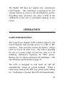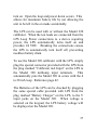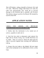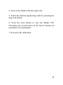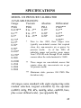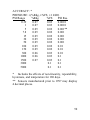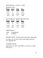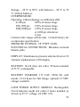
1
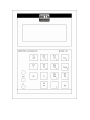
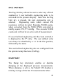
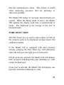
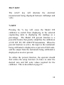
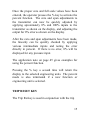
MODEL 320
PRESSURE CALIBRATOR
& LOOP
POWER SUPPLY
USER’S GUIDE
TABLE OF CONTENTS
INTRODUCTION
Page
General Description………...…………………….4
Model 320 Calibrator…………………..…………4
Loop Power Supply (LPS)………………..………4
Battery Charging………………….………………5
Operation – Model 320 Calibrator
Power On Sequence…………………..…………..6
Battery Check - Model 320 Calibrator…...……….9
Battery Check - Loop Power Supply………...……9
Select Key..............................................................10
Zero Key................................................................10
Min/Max Key.........................................................11
Eng Units Key........................................................12
Damp Key..............................................................12
Port Select Key.......................................................13
mA/V Key..............................................................14
% Key.....................................................................14
Trip Reset Key........................................................15
Clear Key................................................................17
Setup Key and Menus.............................................17
User Eng..........................................................18
Batt. Save........................................................20
% Function......................................................21
H2O Ref..........................................................24
Owner..............................................................24
1
Calibration.......................................................26
Trip Detect.......................................................33
Input Functions
Volts........................................................................34
Milliamps................................................................34
Pressure...................................................................35
Differential
Absolute
Vacuum
Operation - Loop Power Supply
Power On/Off Sequence.........................................36
Battery Check.........................................................36
How To Use The LPS.............................................36
Application Notes
Using the Model 320 Calibrator With A
Hand Pump.…………………………………….....38
Using the LPS..........................................................41
Pressure Switch Calibration Using Trip
Detect.........……………………………………......43
Calibrating a Pneumatic Transmitter.......................44
Calibration Using % Function.................................45
2
Appendix
A. Entering Alphanumeric Data..............................47
B. Pressure Conversion Factors..............................48
Specifications
Pressure...................................................................50
mA/V.......................................................................51
Environmental.........................................................51
Service Information
Warranty.................................................................53
Return For Calibration/Repair................................54
3
INTRODUCTION:
GENERAL DESCRIPTON
The Model 320 pressure calibrator is a compact,
versatile, functionally styled calibrator. The unit is
menu driven, so technicians can immediately begin
using it to its fullest capabilities without extensive
training.
The Model 320 faceplate consists of three functional
areas:
At the top is a two line, alphanumeric liquid crystal
display (LCD) for simltaneous indication of pressure
and milliamps/volts readings and operator prompting.
The center section is a membrane keypad for operator
entry.
The lower left section contains recessed input jacks
for connecting the supplied test leads to the device
being calibrated.
The pressure connectors are at the lower end of the
case and are 1/8” FNPT.
The Loop Power Supply (LPS) is an option that
provides 24 VDC to power the device under test if
4
desired. The LPS is stored in a pouch under the
Model 320 calibrator for easy access.
BATTERY CHARGING
Units are shipped with the internal batteries in an
uncharged state. Before using the Model 320 or the
LPS as a portable unit, it is necessary to charge the
batteries for a minimum of 14 to 16 hours. The
calibrator battery charger is a wall plug-in type (see
below) that connects to a jack on the right-hand side
of the instrument. Battery operation time is 50 hours,
typically for the Model 320 and 6 hours nominal at 20
milliamps for the LPS.
5
OPERATION:
The Model 320 calibrator is user friendly and menu
driven. A first time user can normally start operating
the unit with few or no instructions. The following
information is intended to provide a detailed
understanding of the unit.
POWER ON SEQUENCE
The calibrator is turned on or off by pressing the
On/Off key. Each time it is turned on, a series of
internal tests and calibrations are performed. The
start-up procedures provide a pass/fail test of certain
internal circuitry. If the tests determine the unit has an
internal failure, a fault message is displayed and the
unit will not operate. Refer to the Service Information
on page 54 for information on how to contact the
factory.
The start-up calibrations provide for dynamic
recalibration of the internal calibrator support
circuitry, by applying the primary reference voltages
to points in the circuitry and recording the readings as
references for further measurements. The start-up
6
auto calibration does not in any way affect the primary
calibration done at the factory or at a field metrology
lab using available software and suitable standards.
During the time the start-up tests and calibrations are
being performed, certain informational displays are
presented to show the status of the calibrator. The
first message displayed will be:
Beta Gauge
01/04/94
This indicates the date in MM/DD/YY format of the
last factory calibration. The example indicates the
Model 320 was calibrated on Jan. 4, 1994. If the unit
has been recalibraed in the field, the date will be
displayed in a MM-DD-YY format. See page 26 for a
description of the calibration procedure.
The next display will be:
property of
YOUR NAME HERE
7
This gives the name of the owner of the calibrator.
The preceding display shows the default setting as the
calibrator is shipped. The name can be changed
through the operator setups. See page 24 for how to
change the owner’s name.
The next display will be:
Auto Calibration
in progress
This display will remain until the internal tests and
calibrations are finished. If the auto calibration
message fails to clear, the unit must be returned for
service. See page 54 for details. The next display will
be the functions that had been selected when the
calibrator was last used:
inH2O
0.0
mA
0.000
This display indicates the calibrator is operating
properly and is ready to go to work.
8
BATTERY CHECK
The Bat Ck key may be pressed at any time after
completion of the calibrator startup routine to diplay
the current batttery voltage for approximately 1
second before the normal display returns. The current
input funciton is not disturbed by making a battery
check measurement.
The battery voltage of the Model 320 calibrator should
be between 5.3 and 4.6 volts. When the voltage falls
below 4.8 volts, a warning message is displayed
approximately every minute. When the voltage falls
below 4.6 volts for 1 minute, the calibrator will turn
itself off to prevent damage to the batteries due to
possible reversal.
The batteries of the LPS are checked by plugging the
cable provided with the LPS into the battery charger
jack located on the side of the LPS. The other end of
the cable should be plugged into the Model 320 V
input. When voltage is selected on the keypad, the
LPS battery voltage will be displayed on the Model
320.
9
The LPS battery voltage should be between 10.6 and
9.2 volts, indicating a full charge. When the voltage
falls below 8.8 volts, the LPS will turn itself off to
prevent damage to the batteries due to possible cell
reversal.
SELECT KEY
The Select Key is used for two functions. First, while
in Setup, pressing Select will switch the dispay from
two sets of menu screens. Second, Select is used in
the field calibration described on page 26.
ZERO KEY
When the Model 320 is first turned on, a small zero
offset may appear. Pressing the zero key wil eliminate
it. A warm up of up to four minutes may be required
to achieve nominal accuracy. For absolute pressure
sensors only, the following procedure may be used.
Press the Zero Key. The calibrator will request the
user to enter the calibration access code (found on the
factory calibration data sheet.) After entering the code
and pressing the enter key, the calibrator will prompt
the user to enter the new zero (actual barometric
10
pressure). A barometric standard of at least .025%
accuracy should be used to determine atmospheric
pressure. When entering this value, proper decimal
place entry must be observed.
The “Zero” key is inactive during user calibration.
Only numeric entry (9) is active in this mode.
MIN/MAX KEY
The Model 320 calibrator constantly monitors the
displayed readings and stores the minimum and
maximum values internally.
Pressing the Min/Max key will cause the minimum
and maximum values to be displayed. The maximum
values will be displayed on the top line and the
minimum values will be displayed on the bottom line.
Pressing the Min/Max key a second time will return
the Model 320 to a normal display mode and will reset
the minimum and maximum values to the current
reading.
The minimum and maximum values are also reset
whenever a new function or engineering unit is
selected.
11
ENG UNIT KEY
The Eng Unit key allows the user to select any of the 8
standard or 1 user definable engineering units to be
activated for the pressure display. Each time the Eng
Unit key is pressed, the next engineering unit is
selected.
Engineering units which exceed PSI
resolution, will not be valid. Example, 50,000 counts,
when converted from the 5000.0 PSIG converted to
mmHg equals 258,575 mmHg. This exceeds 50,000
counts and will not be an active unit of measurement.
If a user defined engineering unit has been entered, it
is displayed as the 9th entry. The user defined entry
can always be identified by a “u” in the first position,
followed by the name.
The user defined engineering uits are configured from
the operator setup functions (UsrEng).
DAMP KEY
The Damp key alternately enables or disables
damping of the displayed pressure measurements.
When damping is active, the Model 320 displays a
running average of the last 16 measurements rather
12
than the instantaneous values. This feature is useful
when measuring pressures that are pulsating or
otherwise unstable.
The Model 320 makes 2-3 pressure measurements per
second. When the Damp mode is active, the Model
320 updates the display each time a measurement is
made. The displayed is the average of the last 16
measurements.
PORT SELECT KEY
The Port Select key is used to select either or both of
the pressure ports to be displayed on dual sensor 320
calibrator models.
If the Model 320 is equipped with dual pressure
sensors, pressing the Port Select key will alternately
select the left port, the right port, or both ports.
If both ports are selected, the Model 320 will display
both pressures simultaneously but milliamps or volts
cannot be displayed.
If one port is selected, the Model 320 will display one
pressure and either milliamps or volts.
13
MA/V KEY
The mA/V key will alternate the electrical
measurement being displayed between milliamps and
volts.
% KEY
Pressing the % key will cause the Model 320
calibrator to switch from displaying in the selected
engineering units to displaying the readings as a
percentage. The Model 320 percent function is a
powerful feature that greatly simplifies the calibration
of I/P, E/P, P/I, P/E AND P/P transmitters. When the
percent function is active, the input to the instrument
being calibrated is displayed as a percent of full scale,
and the output from the instrument being calibrated is
displayed as an error percent.
To utilize the percent function, the operator should
first utilize the setup function (% func) to enter the
desired zero and full scale values required for the
calibrator. This is described on page 21.
14
Once the proper zero and full scale values have been
entered, the operator presses the % key to activate the
percent function. The zero and span adjustments to
the transmitter can now be quickly adjusted by
applying aproximately 0% and 100% inputs to the
transmitter as shown on the display, and adjusting the
output for 0% error as shown on the display.
After the zero and span adjustments have been made,
the linearity can be quickly checked by applying
various intermediate inputs and noting the error
directly in percent. If there is no error, 0% will be
displayed for any pressure input.
The application note on page 45 gives examples for
using the percent function.
Pressing the % key a second time will return the
display to the selected engineering units. The percent
mode is also terminated if a new function or
engineering unit is selected.
TRIP RESET KEY
The Trip Rst key is used in conjunction with the trip
15
detect mode that is available through the setup menus.
When trip detect is active, the Model 320 calibrator
will monitor the electrical measurement for a
significant change of state. When a change of state is
detected, the last pressure measurement is frozen on
the display, and the message “tripped” is displayed
over the electrical measurement.
When the Trip Rst key is pressed, the Model 320 will
resume displaying the instantaneous pressure and
monitoring for a change of state at the electrical
terminals.
The message “ready” will be displayed over the
electrical measurement.
A change of state is signified by a 10% change in
either the volts or milliamps reading. When trip detect
is active, voltage measurements will be made on the
30 V scale and milliamps measurements will be made
on the 50 mA scale. The Model 320 makes 2-3
electrical measurements per second. To guarantee that
the change of state will be detected, the change must
exist for a minimum of ½ second.
For a hook-up diagram, refer to the application note
on page 43.
16
CLEAR KEY
The Clear key allows the operator to re-enter an
incorrect numeric entry. When the Model 320
calibrator is expecting a numeric entry, a ?????
prompt is displayed. As numeric keys are pressed, the
value is echoed on the display. If a keying error is
made, press Clr to cancel the value entered and return
to the ????? prompt.
SETUP KEY AND MENUS
The Setup key allows the user to perform certain
custom operations with the Model 320 calibrator.
When the Setup key is pressed, the display will
display two menus of items that are configurable by
the operator. Pressing the Select key will bring up a
second menu display. Pressing the Select key again
will bring back the original menus. Pressing the Enter
key will clear the Setup mode and the Model 320 will
resume its normal display.
All of the user setup parameters are retained when the
Model 320 is turned off.
17
Next to each menu in Setup is a number. Pressing that
number on the keypad allows the operator to configure
that specific item.
1 = UsrEng (User Defined Engineering Unit)
This allows the user to enter a custom engineering uit
coversion. The conversion factor to be entered is the
conversion from 1 PSI. Up to 6 significant digits can
be entered, however, the Model 320 calibrator will
display a maximum of 50,000 counts.
The Model 320 will display the user defined
engineering units with the same number of decimal
places that were entered as the conversion factor.
Enter the desired conversion and press Enter. If you
make a mistake while entering the value, press the Clr
key to allow the value to be re-entered. If the Clr key
is pressed while the ????? prompt is displayed, the
user defined engineering units are made invalid, and
will not be displayed when the Eng Unit key is
pressed.
18
After the conversion value is entered, the name for the
new units can be entered. The name consists of 1 to 5
alphanumeric characters that are selected by entering
their decimal equivalent. Appendix A gives additional
information on this. If you do not choose to enter a
name, press the Clr key and a default name of USER
will be applied.
As an example, to set up a user defined scale for
standard atmospheres where 1 PSI = .06805
atmospheres, enter the following:
enter 1PSI equiv
?????
Enter .06805 and press the Enter key.
enter units name
USER
?????
19
The name shown in the lower left is the last name that
has been entered. To enter Atmos as the name, you
would enter the following values (press Enter after
each value) 65, 116, 109, 111, 115. (See Appendix
A).
Press <Ent > for any undesignated letter to exit the
routine. If all 5 are used, exiting will be automatic
after the fifth entry.
To access the new user defined units, press the
EngUnit key until Atmos is displayed as the
engineering units.
2 = BattSv (Battery Save)
The battery save feature will turn the calibrator off if
there is no keyboard activity for 30 minutes. This
prevents running the batteries down if the unit is
accidentally turned on, or if the unit is left unattended.
Battery Save should be on unless you have a specific
application where the calibrator needs to run
unattended for greater than 30 minutes. New units are
shipped with Battery Save “On”.
Battery Save
1 = On 2 = Off
20
Press either 1 or 2 using the numeric keys to turn
battery save on or off.
3 = %func (Percent Function)
The percent function allows the operator to specify the
zero and full scale values for a calibration to be
performed. The Model 320 calibrator will then
automatically calculate the percent of error based on
this information.
When the Percent Setup is selected, the operator is
prompted to enter the zero and full scale values for the
input to the transmitter and the zero and full scale
values for the output from the transmitter. The first
prompt screen, for entering the transmitter input zero
value is:
enter input z
+ 0 ?????
The current value is shown in the lower left. If there
is no change required, simply press Enter to accept the
current value. Otherwise, enter the desired value and
press Enter.
21
Note that the input will be a pressure value for P/I or
P/P transmitters, and will be a voltage or milliamp
value for an I/P or E/P transmitter.
After the input zero is entered, the next screens will
prompt for input full scale, output zero, and output full
scale:
enter input FS
+ 100 ?????
enter output z
+ 4 ?????
enter output FS
+ 20 ?????
After the zero and full scale values are entered, the
operator will be prompted to define the type of
instrument being calibrated.
22
1 = I/P
3 = P/P
2 = P/I
Select I/P for transmitters that accept a current or
voltage as an input and produce a pressure as an
output.
Select P/I for transmitters that accept a pressure as an
input and produce a current or voltage as an output.
Select P/P for pneumatic transmitters that accept a
pressure as and input and produce a pressure as an
output. The P/P selection is only available on a Model
320 that is equipped with two (2) pressure sensors.
If the P/P selection is made, an additional prompt
screen will be displayed:
1 = input on left
2 = input on right
Select “1” if the pressure input to the pneumatic
transmitter is being measured on the left port of the
Model 320.
23
Select “2” if the pressure input to the pneumatic
transmitter is being measured on the right port of the
Model 320.
After the percent function setup is completed, the
function is activated by pressing the % key.
4 = H2Oref (H2O Reference Temperature)
The H2O Reference refers to the temperature
correction for inches and centimeters of water
measurements. There are three choices: 20 °C, (ISA
Standard); 4 °C, (Scientific Standard); and 60 °F,
(American Gas Association Standard). Press the
number for the desired temperature correction.
1 = 20C
3 = 60F
2 = 4C
5 = Owner (Change Owner’s Name)
The Model 320 calibrator contains a security feature
that allows the owner to enter a name or other
24
identifying information into the calibrator’s
nonvolatile memory. The owner’s name cannot be
changed unless the operator knows the unit's access
code.
The access code is unique to each calibrator and is
printed on the individual calibration sheet that is
shipped with each calibrator.
When a new calibrator is received, the owner should
enter the desired owner name and file the access code
in a safe place for future reference. DO NOT keep the
access code with the calibrator.
When the owner setup is selected, the operator is
prompted to enter the access code. Enter the access
code from the calibration sheet and press Enter. If the
correct code is entered, the next display will be the
current owner name on the top line.
YOUR NAME HERE
The name of the owner can be any alphanumeric
combination of characters up to a maximum of 16.
The characters are assigned by entering the decimal
25
value of the desired character. Appendix A lists the
values for each character.
To advance to the next position without changing the
existing character, press Enter while the ????? prompt
is showing. To back up to previous position, press Clr
while the ????? prompt is showing. Press the
<
ENT > key repeatedly to exit the routine.
6 = Calib (User Calibration)
The Model 320 is a fully digital instrument that
employs advanced software correction algorithms to
allow the instrument to be fully calibrated without the
use of any analog adjustments, i.e., trim pots. The
Model 320 allows all parameters except temperature
compensation to be adjusted from the keypad.
CALIBRATION SHOULD ONLY BE ATTEMPTED
BY
QUALIFIED
PERSONNEL
HAVING
SUITABLE
METROLOGY
STANDARDS
AVAILABLE.
The parameters that are adjusted and the required
reference sources are listed below:
26
Function to calibrate
Volts In
mA In
pressure; zero, span
linearity
Required ref source
10VDC ± .01%
20mA ± .01%
pressure at 0%, 25%,
50%, 75%, 100% of
scale. Accuracy should
be 3 times better than the
Model 320 range.
The sequence required to perform the calibrations is
(1) apply the required calibration source, (2) observe
the reading on the Model 320, (3) if the reading on the
320 is outside of the required tolerance, enter the
desired reading. If the reading is correct, proceed to
the next calibration step.
The pressure ranges are calibrated using the
engineering units that were selected when calibration
mode is activated. Ensure that the proper engineering
units are selected before entering the calibration mode.
Also be sure to select the proper temperature
compensation value if inches of water column are
selected. The temperature compensation value should
be the same for the Model 320 and the pressure
source.
27
To place the Model 320 into the calibrate mode, press
6 (user cal) while in set up mode, screen number 2.
The unit will prompt for the access code to be entered.
enter access code
?????
Enter the calibration access code from the individual
calibration data sheet that is supplied with the unit. If
the correct access code is entered, the Model 320 will
enter the calibration mode as shown below.
volts user cal
+ 10.000 volt in
The following keys are active during calibration
mode.
28
Select – proceed to the next calibration step.
Clr – If depressed while a user calibration step is
active, ????? will be displayed prompting the user to
enter the new calibration value from calibration
source. If depressed during numeric entry, it functions
as the normal clear entry key.
Enter and number keys – used to enter calibration
values
Calibration values are entered as counts without any
decimal places.
For example, when calibrating
milliamps, the display might show 19.997. If the
calibration source is 20.000 mA, you would press Clr
and then enter 20000.
The followwing table lists the calibration steps and the
required procedure to use.
The basic procedure for each step is to:
1. Apply the requested input source.
2. Observe the reading on the Model 320.
3. If the reading is outside of limits, press Clr and
enter the correct value.
29
4. If the reading is within the required limits, press
Select to progress to the next step.
After the last calibration step, the user is prompted to
enter the date. THE CALIBRATION DATA IS NOT
SAVED UNTIL A DATE IS ENTERED.
DETAILED PROCEDURE
1. Insure that the Model 320 to be calibrated by means
of the user calibration mode is temperature stable at
25 degrees C ±5 degrees. Any deviation will induce
temperature compensation correction inaccuracies.
2. Press the “set up” key. Select 6 from menu #2. To
display the second menu screen, press the select key
while in the setup mode. Next the user will be
prompted to enter the user calibration code from the
unit’s calibration data sheet. When the correct access
code is entered from this data sheet, functions to be
calibrated will be displayed in the following order.
Function
Volts input
Milliamp input
Required Reference Value
10.000
20.000
30
Left pressure zero
Vent for gauge, and gauge
vacuum, 0.003 PSI or less
for absolute
Left pressure Span
Left pressure 25%
Left pressure 50%
Left pressure 75%
(enter date single
sensor)
Right pressure zero
FS – range dependent
25% of FS
50% of FS
75% of FS
Right pressure Span
Right pressure 25%
Right pressure 50%
Right pressure 75%
(enter date dual
sensor)
Vent for gauge, and gauge
vacuum, 0.003 PSI or less
for absolute
FS – range dependent
25% of FS
50% of FS
75% of FS
If you have entered the user calibration mode and do
not wish to change any calibration values simply press
the Select Key to bypass each step. Bypassing each
step with the Select Key will preserve the original
calibration providing that the Clr Key has not been
depressed at any point. Enter the date per prompt to
31
exit the calibration mode. To calibrate electrical or
pressure functions proceed as follows.
3. Apply a 10 volt signal to the volts input. If
adjustment is required press the CLR key. Next, enter
the correct reference voltage value. Calibration values
are entered in counts without any decimal places.
Enter 10000 for 10.000 volts. Repeat the sequence if
necessary to acquire a proper calibration. When you
are satisfied with the calibration press the Select key
to proceed to the next calibration step.
4. The next screen will display the milliamp
calibration. Calibrate the full scale mA at 20.000 mA.
Use the CLR and Select key as previously described.
5. The next prompt will be for the left pressure port.
The sequence will be zero, span, 25%, 50%, and 75%
of full scale. When using a dead weight tester the
exact percent of scale may not be possible. The
percent of scale need not be exact but, should be as
close as possible. Many times only the zero and span
will need adjustment. As in the previous sequences,
apply the correct reference, use the Clr key to clear the
reading, enter the new reference reading in counts
without decimal places, press “ent” to enter the new
value, and select key when finished to proceed to the
32
next calibration step..
points to be calibrated.
Repeat this process for all
At the end of the pressure calibration sequence you
will be prompted for the current date. The format is
MMDDYY.
CALIBRATION DATA IS NOT
SAVED UNTIL A DATE IS ENTERED.
7 = Trip (Trip Detect)
The trip detect setup function allows trip detect to be
turned on or off:
trip detect
1 = on
2 = off
The operation of the trip detect function is explained
on page 15 and 16 under the Trip Rst key.
33
INPUT FUNCTIONS
VOLTS
The Model 320 measures voltage at the volts terminals
at the lower left corner of the keypad area. The
negative terminal is common to volts and milliamps
measurements.
To measure voltage, press the V/mA Key, until Volts
is displayed on the upper line of the LCD display. If
you have a Model 320 wih 2 pressure sensors, you
must first ensure that volts/mA are available by
pressing the Port Select key.
There are 2 voltage ranges and the Model 320
autoranges between them. The ranges are 0-10.000V
and 0-30.00V. When the input voltage exceeds
approximately 11 volts, the Model 320 will change to
the 30V scale. When the input voltage falls below
10.5 volts, the Model 320 switches back to the 10V
scale.
MA
The Model 320 measures current at the mA terminals
34
at the lower left corner of the keypad area. The
negative terminal is common to volts and milliamps
measurements.
To measure current, press the V/mA Key, until
milliamps is displayed on the upper line of the LCD
display. If you have a Model 320 with 2 pressure
sensors, you must first ensure that volts/mA are
available by pressing the Port Select key.
There are 2 current ranges and the Model 320
autoranges between them.
The ranges are 020.000mA and 0-50.00mA. When the input current
exceeds approximately 22 mA, the Model 320 will
change to the 50mA scale. When the input current
falls below 21 mA, the Model 320 switches back to
the 20mA scale.
PRESSURE
The model 320 measures pressure at the 1/8” FNPT
port at the base of the unit. Units with 2 pressure
sensors or one differential sensor will have 2 ports.
The full scale pressure for the individual port(s) is
shown at the base of the keypad, directly above the
pressure port(s).
35
The Model 320 does not employ any overpressure
relief bypass. The maximum overpressure for the
various sensors is given in the specifications section.
Exceeding these pressures can cause a shift in the
calibration of the unit or permanent damage to the
sensor.
OPERATION
LOOP POWER SUPPLY
The Loop Power Supply (LPS) contains eight (8) AA
Ni-Cd batteries that provide power to a DC to DC
converter. This converter boosts the battery voltage
(10.6 to 9.2) to 24 VDC ±5%. The LPS is intended
for use as a power suppy for any two wire, 4 to 20
milliamp instrument requiring 24 VDC power.
Battery life is 6 hours nominal at 20 milliamps. Full
specifications can be found on page 51.
The LPS is designed to turn itself on and off
automatically, based on current demand. When a
series loop exists at the LPS loop power jacks calling
for .5 milliamps or greater, the LPS will automatically
36
turn on. Open the loop and power down occurs. This
allows for maximum battery life by not allowing the
unit to be left in the on mode accidentally.
The LPS can be used with or without the Model 320
calibrator. When the test leads are connected from the
LPS Loop Power connections to a device requiring
power, the LPS automatically turns itself on and
provides 24 VDC. Breaking the connections causes
the LPS to automatically turn itself off, preventing
needless battery drain.
To use the Model 320 calibrator with the LPS, simply
plug the special connector provided with the LPS from
the plug marked “Calibrator mA Input” on the LPS to
the Model 320 milliamp input terminals. This
automatically puts the Model 320 in series with the 4
to 20 mA loop. Reference page 42.
The Batteries of the LPS can be checked by plugging
the same special cable provided with LPS from the
plug marked “Battery Charger” on the LPS, to the V
input jacks on the Model 320. When voltage is
selected on the keypad, the LPS battery voltage will
be displayed on the Model 320.
37
The LPS battery voltage should be between 10.6 and
9.2 volts. When the voltage falls below 8.8 volts, the
LPS will automatically turn itself off to prevent
damage to the batteries due to possible cell reversal.
The battery charger used for the Model 320 should be
used for the LPS.
APPLICATION NOTES
USING
THE
MODEL
320
PRESSURE
CALIBRATOR WITH A HAND PUMP
1. Safely take the instrument to be tested out of
service, equalize it, and vent it.
2. Vent the low side to atmospere and connect the
high side as shown, being very careful that there are
no leaks. Note: It is best to drain the high and low
sides to prevent liquids from entering the calibration
tubing.
3. Connect the test leads to the Model 320 mA input
and to the instrument to be calibrated to form a series
loop.
38
4. Turn on the Model 320 and select mA.
5. Select the desired engineering units by pressing the
Eng Unit button.
6. Press the Zero button to zero the Model 320.
Checking zero several times in the first 4 minutes of
operation is recommended.
7. Proceed with calibration.
39
Transmitter Calibration
Using Pressure Pump
40
USING
THE
MODEL
320
PRESSURE
CALIBRATOR AND LPS WITH A HAND PUMP
1. Safely take the instrument to be tested out of
service, equilize it, and vent it.
2. Vent the low side to atmosphere and connect the
high side as shown, being very careful that there are
no leaks. Note: It is best to drain the high and low
sides to prevent liquids from entering the calibration
tubing.
3. Connect the special connector to the Model 320 mA
input.
4. Connect the test leads to the LPS at the loop power
connection and to the instrument to be calibrated,
being careful to observe the correct polarity.
5. Turn on the Model 320 and select mA.
6. Select the desired engineering units by pressing the
Eng Unit key.
7. Press the Zero key to zero the Model 320.
Checking zero several times in the first 4 minutes of
operation is recommended.
8. Proceed with calibration.
41
Transmitter Calibration
Using Loop Power Supply
(LPS)
42
Pressure Switch Calibration
Using Trip Detect
43
Calibration of a Pneumatic
Flow Transmitter
44
CALIBRATION USING % FUNCTION
You can use the % Function to calibrate a P/I pressure
transmitter.
For this example we will calibrate a pressure
transmitter that has a manufacturer’s range of 0-50
PSIG. The desired calibration will be 0-25 PSIG for a
4-20 mA output. We are using a Model 320 with a 30
PSIG range.
Press Setup-3 to enter the percent function setup
mode. Enter the following values in response to the
prompts:
Enter input Z
0
Enter input FS
25
Enter output Z
4
Enter output FS
20
1=I/P 2=P/I 3=P/P
2
The Model 320 will then exit the setup mode and
resume a normal display. Press the % key to activate
the percent function. With the pressure vented to the
transmitter, you should see a display similar to this:
% scale
+0.00
%error
-1.25
45
This shows that the pressure input to the transmitter is
at +0.00% of scale, and the milliamp output is 1.25%
low. If the % of scale reading is not 0%, you can
press the Zero Key to acquire a new zero reference.
Change the zero adjustment on the transmitter until
the % error reading is 0%. Now apply pressure to the
transmitter and Model 320 and adjust the pressure
until the % scale reading is 95-100%. Change the
span adjustment on the transmitter until the error
reading is 0%.
Repeat the zero and span adjustments until the % error
readings are within the accuracy required.
Since the Model 320 calculates the % of error at any
pressure input, the adjustments can be quickly made.
After the zero and span adjustments are made, the
linearity can be quickly checked at 25, 50 and 75% of
scale and the error % read out directly.
46
APPENDIX A
Entering Alphanumeric Data
The user is required to enter alphanumeric data when
changing the owner’s name and configuring user
defined engineering units. Since the Model 320 does
not have an alphanumeric keyboard, the characters are
entered by using the decimal equivalent of each
character from the table below.
32
33
34
35
36
37
38
39
40
41
42
43
44
45
46
47
48
49
50
51
52
53
54
55
sp
!
“
#
$
%
&
‘
(
)
*
+
,
.
/
0
1
2
3
4
5
6
7
56
57
58
59
60
61
62
63
64
65
66
67
68
69
70
71
72
73
74
75
76
77
78
79
8
9
:
;
=
?
@
A
B
C
D
E
F
G
H
I
J
K
L
M
N
O
80
81
82
83
84
85
86
87
88
89
90
91
92
93
94
95
96
97
98
99
100
101
102
103
P
Q
R
S
T
U
V
W
X
Y
Z
[
¥
]
^
_
a
b
c
d
e
f
g
104
105
106
107
108
109
110
111
112
113
114
115
116
117
118
119
120
121
122
123
124
125
126
127
h
i
j
k
l
m
n
o
p
q
r
s
t
u
v
w
x
y
z
<
1
>
→
←
47
APPENDIX B
Pressure Conversion Factors
The factors used by the Model 320 Calibrator to
convert from PSI to other enineering units aare listed
below.
2.036
51.715
6.8948
68.948
.068948
27.681
27.707
27.730
70.310
70.376
70.433
“Hg
mmHg
KPascals
milliBars
Bars
“H2O
“H2O
“H2O
cmH2O
cmH2O
cmH2O
@ 0ºC
@ 0ºC
@ 4ºC
@ 60ºF
@ 20ºC
@ 4ºC
@ 60ºF
@ 20ºC
If conversions at full scale exceed the maximum
50,000 count resolution, the converted engineering
unit becomes invalid and will not display.
48
SPECIFICATIONS
MODEL 320 PRESSURE CALIBRATOR
AVAILABLE RANGES:
Gauge
Vacuum
Absolute
Differential
PSIG
PSIG
PSIA
PSID***
0-0.39**
0 to –1**
0-15*
0-1**
0-1**
0 to –5**
0-30*
0-5**
0-5*
0 to –15**
0-50*
0-30**
0-7.8*
0-50**
*
Prior to Jan. 2002, these ranges were
0-15*
typically non-isolated sensors that required
0-30*
clean, dry, non-corrosive air or gasses for
0-50*
pressure media.
As of Jan. 2002, all
0-100*
aabsolute ranges and positive gauge ranges
from 5 PSI full scale through 5k are isolated
0-150*
sensors where the wetted material is 316SS.
0-300
0-1000
** These ranges are non-isolated sensors that
0-1500
0-3000
0-5000
require clean, dry, non-corrosive air or gas
for pressure media.
*** Maximum static pressure 200 PSIG Plus
deviations only.
All ranges come standard with eight engineering units
readout selection, keypad selectable by the operator
(inH2O, inHg, PSI, kPa, mmHg, mbar, cmH2O, bars,
plus a user defined scale). [see appendix B]
49
ACCURACY: *
PRESSURE: ±(%Rdg, ±%FS, ±1 LSD)
%Rdg
%FS
PSI Res.
PSI Range
0.39
0.07
0.03
0.0001
1
0.07
0.03
0.0001
5
0.05
0.02
0.001**
7.8
0.05
0.02
0.001
15
0.05
0.02
0.001
30
0.05
0.02
0.001
0.05
0.02
0.001
50
100
0.05
0.02
0.01
150
0.05
0.02
0.01
0.06
0.03
0.01
300
1000
0.06
0.03
0.1
0.07
0.03
0.1
1500
0.1
0.1
3000
5000
0.1
0.1
* Includes the effects of non-linearity, repeatability,
hysteresis, and temperature for 180 days.
** Sensors manufactured prior to 1997 may display
4 decimal places.
50
ELECTRICAL: ±(%FS, ±1 LSD)
Standard Units:
Res.
Range Units %FS
0-10
V
0.025 0.001
0-30
V
0.1
0.01
0-20
mA
0.025 0.001
0-50
mA
0.1
0.01
CSA Approved / Intrinsically Safe Units:
Range Units %FS
Res.
0-10
V
0.05
0.001
0-30
V
0.1
0.01
0-20
mA
0.05
0.001
0-50
mA
0.1
0.01
IMPEDANCE:
Volts 1 MegaOhm
mA
25 Ohms
RESOLUTION: 50,000 counts maximum, depending
on range (see accuracy table) and engineering unit
(see appendix B).
TEMPERATURE:
Operating: 0 to 50ºC (No Effect on Accuracy within
this range.)
51
Storage: -30 ºC to 50ºC, with batteries; -30 ºC to 70
ºC without batteries.
OVERPRESSURE:
Operating, without damage or calibration shift:
0-100 psi
300% of sensor range
300-1500 psi
150% of sensor range
2000-5000 psi 150% of sensor range
or 6100 psi whichever
is less.
Custom order ranges will deviate. Consult factory for
overpressure specification.
PRESSURE FITTINGS: 1/8” FNPT 316SS.
ELECTRICAL CONNECTIONS: Miniature recessed
banana jacks.
DISPLAY: Simultaneous pressure and electrical on 32
character alphanumeric LCD display.
BATTERY: Ni-Cd (four AA cells); 50 hours nominal
at 25 ºC, rechargeable.
BATTERY CHARGER: 115 VAC, 50/60 Hz, wall
mount; 12-14 hours for full charge; optional 12 VDC
charger available.
LOOP POWER SUPPLY MODULE: Rechargeable
Ni-Cd batteries (eight AA cells); 6 hours nominal @
20 mA @ 25 ºC; voltage, 24 VDC ±5%.
52
WARRANTY
Beta Calibrators devices are warranted to be free from
all latent defects in material and workmanship under
normal use and service.
Should any of Beta
Calibrators’ devices to be found within one (1) year
from date of shipment to be defective, Beta will repair
such part and return to buyer FOB Beta’s plant or will
furnish FOB Beta’s plant a similar part to replace it,
provided written notice of such defect is given to Beta
within ten (10) days after the discovery of such defect
and provided the original part is returned to Beta’s
plant with transportation charges prepaid.
THE FORGOING WARRANTIES ARE IN LIEU OF
ALL OTHER WARRANTIES, EXPRESSED OR
IMPLIED, INCLUDING BUT NOT LIMITED TO
THE
IMPLIED
WARRANTIES
OF
MERCHANTABILITY AND FITNESS FOR A
PARTICULAR PURPOSE.
53
SERVICE INFORMATION
Return for calibration, recertification or repair.
It is recommended that each calibrator be recalibrated
and/or recertified on a 6 month basis, against precision
standards that are traceable to the National Institute of
Standards and Technology.
All returns should include a statement on the work
requested and the exact address to which the unit
should be returned. Beta Calibrators will return units
on a prepaid basis.
RETURN AUTHORIZATION
All equipment and/or parts to be returned to Beta
Calibrators for repair or credit must have a Beta
Calibrators Return Authorization Form. This form
will be issued by the Beta Calibrators Customer
Service (972) 241-2200 for credit, or the Beta
Calibrators Service Department (800) 537-2181 for
repair.
54
Website: www.betacalibrators.com
Email: [email protected]
When calling for a form, please provide your Purchase
Order Number and an explanation of why equipment
and/or parts are being returned.
After the form has been obtained, return equipment
along with the form and a copy of your Purchase
Order. This will ensure rapid service and/or credit.
Ship Prepaid To:
Beta Calibrators
2309 Springlake Road, Suite 600
Farmers Branch, Texas 75234-5875
Attention: Service Department
55
2309 Springlake Road, Suite 600
Farmers Branch, TX 75234-5875
USA
Copyright 2002 Beta Calibrators