1
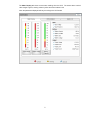
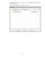
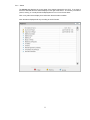
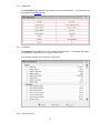
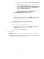
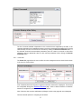
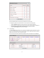
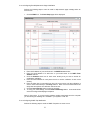
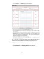
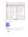
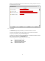
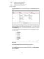
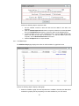
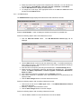
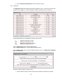
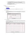
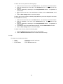
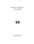
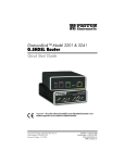
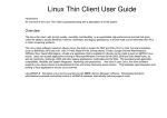
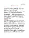
Mitsubishi DiamondLink User Manual Version 4.0.3 DiamondLink 4.0.3 User Manual - Revision * Table of Contents Version 4.0.3 ..................................................................................................................................................... 1 1 WHAT IS DIAMONDLINK? .............................................................................................................................1 2 WHO DO I CONTACT FOR TECHNICAL SUPPORT? ...............................................................................1 3 WHAT ARE THE SYSTEM REQUIREMENTS FOR DIAMONDLINK? ...................................................1 3.1 3.2 4 OPERATING SYSTEM REQUIREMENTS ...........................................................................................................1 WEB BROWSER REQUIREMENTS...................................................................................................................2 HOW DO I INSTALL DIAMONDLINK?.........................................................................................................2 4.1 INSTALLING THE DIAMONDLINK SERVER.....................................................................................................2 4.1.1 WINDOWS ....................................................................................................................................................2 Special Requirements for Windows XP Service Pack 2 .............................................................................. 2 4.1.2 4.2 4.2.1 4.2.2 4.2.3 4.2.4 4.2.5 4.2.6 4.2.7 5 LINUX ..........................................................................................................................................................3 INSTALLING THE DIAMONDLINK REMOTE SHUTDOWN AGENT ....................................................................3 WINDOWS ....................................................................................................................................................3 LINUX ..........................................................................................................................................................4 HP-UX.........................................................................................................................................................4 SOLARIS .......................................................................................................................................................4 AIX..............................................................................................................................................................5 NETWARE .....................................................................................................................................................5 MAC OS X ...................................................................................................................................................6 HOW DO I USE DIAMONDLINK? ..................................................................................................................6 5.1 5.2 5.3 STARTING DIAMONDLINK ............................................................................................................................6 DIAMONDLINK USER INTERFACE COMPONENTS ..........................................................................................7 HOME ...........................................................................................................................................................7 5.3.1 Overview .......................................................................................................................................7 5.3.2 Alarms .........................................................................................................................................11 5.3.3 Identification ...............................................................................................................................12 5.3.4 Parameters ..................................................................................................................................12 5.3.5 Attached Devices.........................................................................................................................12 5.3.5.1 5.3.5.2 5.3.5.3 5.3.6 5.3.7 5.3.8 5.3.9 5.3.9.1 5.3.9.2 5.3.9.3 5.3.9.4 5.3.9.5 5.4 5.6 Manual Control...........................................................................................................................14 Power Fail...................................................................................................................................15 Shutdown Events .........................................................................................................................16 Event Settings ..............................................................................................................................17 Defining Event Severity........................................................................................................................ 18 Defining User-Definable Event Categories........................................................................................... 18 Configuring Email/Alphanumeric Pager Notification .......................................................................... 19 Configuring SNMP Trap Notification .................................................................................................. 19 Configuring Network Broadcast Notification ....................................................................................... 20 5.3.10 Settings ........................................................................................................................................22 LOGS ..........................................................................................................................................................22 5.4.1 UPS Summary .............................................................................................................................22 5.4.2 UPS Detailed...............................................................................................................................23 5.4.3 UPS Data ....................................................................................................................................24 5.4.3.1 5.4.3.2 5.5 Adding Attached Devices ..................................................................................................................... 13 Editing Attached Devices ..................................................................................................................... 14 Deleting Attached Devices ................................................................................................................... 14 Log Settings .......................................................................................................................................... 25 Exporting Logs ..................................................................................................................................... 25 5.4.4 UPS Data Graph .........................................................................................................................26 5.4.5 UPS Maintenance........................................................................................................................27 5.4.6 Application ..................................................................................................................................28 SETUP.........................................................................................................................................................29 5.5.1 My Account .................................................................................................................................29 5.5.2 User Accounts .............................................................................................................................29 HELP ..........................................................................................................................................................30 1 What is DiamondLink? DiamondLink is a UPS power monitoring and system shutdown software application. DiamondLink monitors the UPS through a communications cable attached to a serial port on the computer and the communications interface on the UPS. This connection enables the software to monitor the status of the UPS and to perform a graceful operating system shutdown if required. Through a web browser interface you can view the UPS status, configure shutdown timers and event actions, view event history and graph UPS parameters. You can configure the application to perform appropriate actions when an event is detected. The user configurable actions include: broadcasting, e-mail, command file execution and operating system shutdown. For example, if utility power fails, you may wish to broadcast a warning message, send an email and shut down your computer after a configured time delay. You can set the delays and intervals for any of these actions. DiamondLink consists of two components. The DiamondLink server communicates with the UPS and performs all event management. The DiamondLink remote shutdown agent runs on one or more remote computers and communicates with the DiamondLink server to allow remote shutdown of computers powered by the UPS. The entire suite of management products from Mitsubishi includes: MultiLink – monitor up to one thousand devices including UPSs, PDUs, rack and environmental monitors and IP cameras DiamondLink – UPS management and system shutdown software NetCom – SNMP/Web UPS management card 2 Who Do I Contact For Technical Support? For help on configuring and using DiamondLink or any Mitsubishi UPS product, contact the Technical Support group at: Phone Fax Email Web 724-772-2555 724-778-3146 [email protected] http://www.meppi.com 3 What are the System Requirements for DiamondLink? Check the Mitsubishi web site (http://www.meppi.com) for the latest list of system requirements. 3.1 Operating System Requirements The DiamondLink server will run on the following operating systems: Windows 2000 Windows 2003 Windows XP Linux Red Hat 7.3, 8.0 Red Hat Enterprise 2.1 ES (update 5), 3.0 ES (update 4) SLES 9.0 1 The DiamondLink remote shutdown agent will run on the following operating systems: Windows 2000 Windows 2003 Windows XP Linux Red Hat 7.3, 8.0 Red Hat Enterprise 2.1 ES (update 5), 3.0 ES (update 4) SLES 9.0 HP-UX 11.0, 11i v1, 11i v2 Sun Solaris 8 Novell Netware 6 IBM AIX 4.3, 5.2 Mac OS X 3.2 Web Browser Requirements Supported web browsers include: Internet Explorer 5.0 or higher Macromedia Flash 6.0 or higher Mozilla Firefox 2.0 or higher 4 How Do I Install DiamondLink? 4.1 Installing the DiamondLink Server The DiamondLink Server should be installed on the computer that is going to be communicating with the UPS. One end of the communications cable should be attached to a serial port on the computer and the other end to the communications interface on the UPS. 4.1.1 Windows Perform the following steps to install the server on Windows: 1. Insert the CD. The installation will start automatically. Reply to the standard prompts. 2. During the installation you will be asked which protocol to use for your UPS model. Select Mitsubishi if your UPS model is a 2033A or 9700. Select SEC for all other UPS models. 3. When the Configuration screen appears, you will have the option to choose whether or not you want to use SSL (secure socket layer) web security. The use of SSL may slow your web access slightly but provides a layer of security above the username/password protection already provided by the application. You can also choose a different web port from the default (the defaults are 80 for a standard web port and 443 for the secure web port). In most cases, the default web port is fine. If you are already running a web server on the computer, you will want to choose a different web port. 4. When the installation has finished, you may be prompted to restart your computer. Special Requirements for Windows XP Service Pack 2 When Windows XP Service Pack 2 is installed on a computer it will turn on the personal firewall. Follow these steps to open up the web port for DiamondLink: Go to Start Menu --> Control Panel. Go to Network Connections and right click on the connection that is being used. Click on Properties and click the Advanced tab in the Properties dialogue. Press the Settings... button to bring up the Firewall dialogue. Go to the Exceptions tab and click the Add Port button. For Name enter DiamondLink Web Port and for Port Number use 80 (or the port that was entered when the application was installed) and press the OK button. You should now be able to access the DiamondLink web port through the XP Firewall. 2 If you will be using DiamondLink to shut down remote systems or to communicate with MultiLink Enterprise software, you will also need to open up the server communications port. Follow these steps to open up the necessary ports for the DiamondLink Remote Agent to work properly. Go to Start Menu --> Control Panel. Go to Network Connections and right click on the connection that is being used. Click on Properties and click the Advanced tab in the Properties dialogue. Press the Settings... button to bring up the Firewall dialogue. Go to the Exceptions tab and click the Add Port button. For Name enter DiamondLink Remote and for Port Number use 3573 and press the OK button. You should now be able to access the DiamondLink communications port through the XP Firewall. IMPORTANT: You can also completely turn off the Firewall instead of adding these ports but Microsoft does not recommend doing this. If you choose to do this, choose the Off option from the General tab. 4.1.2 Linux Perform the following steps to install the server on Linux: 1. 2. 3. 4. Insert the CD. Mount the CD. Browse to the location of the Linux Management Server and run Setup. During the installation you will be asked which protocol to use for your UPS model. Select Mitsubishi if your UPS model is a 2033A or 9700. Select SEC for all other UPS models. 5. You will also be able to choose whether or not you want to use SSL (secure socket layer) web security. The use of SSL may slow your web access slightly but provides a layer of security above the username/password protection already provided by the application. You can also choose a different web port from the default (the defaults are 80 for a standard web port and 443 for the secure web port). In most cases, the default web port is fine. If you are already running a web server on the computer, you will want to choose a different web port. 4.2 Installing the DiamondLink Remote Shutdown Agent The DiamondLink Remote Shutdown Agent should be installed on a computer that is being powered by a UPS but is not communicating to it through the communications cable. Installing this software will allow the server to shut down remote computers when events occur on the UPS. 4.2.1 Windows Perform the following steps to install the remote shutdown agent on Windows: 1. 2. 3. 4. 5. Insert the CD. Browse to the location on the CD for the Windows Agent. Run the Setup file by double-clicking on it. Reply to the standard installation prompts. As an added security option, the Remote Shutdown Agent can be configured to only shut down when it receives a shutdown message from a particular system. From the remote shutdown agent configuration screen, enter the IP address of the machine running the DiamondLink Server software. Leave the field blank to allow any DiamondLink Server to connect to the remote shutdown agent. 6. The shutdown agent can be configured to run in redundant mode. In redundant mode, the computer will only be shut down when all configured systems have sent a shutdown message. To set up the remote shutdown agent to be managed by redundant systems click the radio button labeled This agent will be managed by redundant servers. 3 7. If one or both of the servers managing the remote shutdown agent is a Netcom, check the Netcom checkbox by its IP address. 4.2.2 Linux Perform the following steps to install the remote shutdown agent on Linux: 1. 2. 3. 4. Insert the CD. Mount the CD. Browse to the location of the Linux Management Server and run SetupRA. During the installation you will be asked if the remote shutdown agent will be managed by redundant management servers. 4.2.3 If you do not want to have a redundant setup answer ‘n’ at this prompt. The installation will then ask for the IP address of the managing server. Either enter the specific IP address of the management server or enter a ‘*’ to allow any Management Server to connect to it. After entering the IP address, you will then be asked if the managing server is a Netcom. Enter ‘y’ if the managing server is a Netcom or ‘n’ if not. If you do want to have a redundant setup then answer ‘y’ at this prompt. The installation will then ask for the IP address of the first managing server. Either enter the specific IP address of the management server or enter a ‘*’ to allow any Management Server to connect to it. After entering the IP address for the first server, you will then be asked if it is a Netcom. Enter ‘y’ if the managing server is a Netcom or ‘n’ if not. You will then be asked the same questions about the redundant management server. HP-UX Perform the following steps to install the remote shutdown agent on HP-UX: 1. 2. 3. 4. Insert the CD. Mount the CD. Browse to the location of the HP-UX Management Server and run Install. During the installation you will be asked if the remote shutdown agent will be managed by redundant management servers. 4.2.4 If you do not want to have a redundant setup answer ‘n’ at this prompt. The installation will then ask for the IP address of the managing server. Either enter the specific IP address of the management server or enter a ‘*’ to allow any Management Server to connect to it. After entering the IP address, you will then be asked if the managing server is a Netcom. Enter ‘y’ if the managing server is a Netcom or ‘n’ if not. If you do want to have a redundant setup then answer ‘y’ at this prompt. The installation will then ask for the IP address of the first managing server. Either enter the specific IP address of the management server or enter a ‘*’ to allow any Management Server to connect to it. After entering the IP address for the first server, you will then be asked if it is a Netcom. Enter ‘y’ if the managing server is a Netcom or ‘n’ if not. You will then be asked the same questions about the redundant management server. Solaris Perform the following steps to install the remote shutdown agent on Solaris: 1. 2. 3. 4. Insert the CD. Mount the CD. Browse to the location of the Linux Management Server and run install. During the installation you will be asked if the remote shutdown agent will be managed by redundant management servers. If you do not want to have a redundant setup answer ‘n’ at this prompt. The installation will then ask for the IP address of the managing server. Either enter the specific IP address of the management server or enter a ‘*’ to allow any Management Server to 4 4.2.5 connect to it. After entering the IP address, you will then be asked if the managing server is a Netcom. Enter ‘y’ if the managing server is a Netcom or ‘n’ if not. If you do want to have a redundant setup then answer ‘y’ at this prompt. The installation will then ask for the IP address of the first managing server. Either enter the specific IP address of the management server or enter a ‘*’ to allow any Management Server to connect to it. After entering the IP address for the first server, you will then be asked if it is a Netcom. Enter ‘y’ if the managing server is a Netcom or ‘n’ if not. You will then be asked the same questions about the redundant management server. AIX Perform the following steps to install the remote shutdown agent on AIX: 1. 2. 3. 4. Insert the CD. Mount the CD. Browse to the location of the Linux Management Server and run install. During the installation you will be asked if the remote shutdown agent will be managed by redundant management servers. 4.2.6 If you do not want to have a redundant setup answer ‘n’ at this prompt. The installation will then ask for the IP address of the managing server. Either enter the specific IP address of the management server or enter a ‘*’ to allow any Management Server to connect to it. After entering the IP address, you will then be asked if the managing server is a Netcom. Enter ‘y’ if the managing server is a Netcom or ‘n’ if not. If you do want to have a redundant setup then answer ‘y’ at this prompt. The installation will then ask for the IP address of the first managing server. Either enter the specific IP address of the management server or enter a ‘*’ to allow any Management Server to connect to it. After entering the IP address for the first server, you will then be asked if it is a Netcom. Enter ‘y’ if the managing server is a Netcom or ‘n’ if not. You will then be asked the same questions about the redundant management server. Netware Perform the following steps to install the remote shutdown agent on Netware: 1. Insert CD into the CD-ROM drive of the Netware Client computer. 2. From the Agent\Netware subdirectory of the CD, copy the contents into a directory on the NetWare server. 3. From the NetWare system console, load the configuration module (PMCONFIG.NLM) using the default path. For example, if the files were copied into a folder called Mitsubishi on the SYS: volume, the module would be loaded as follows: SYS:Mitsubishi/PMCONFIG 4. After accepting the License Agreement, you will be asked if your remote shutdown agent will be managed by redundant Management Servers. a. If you do not want to have a redundant setup then answer ‘n’ at this prompt. The installation will then ask for the IP address of the managing server. Either enter the specific IP address or enter a ‘*’ to allow any Management Server to connect to it. After entering the IP address, you will then be asked if the managing server is a Netcom. Enter ‘y’ if the managing server is a Netcom or ‘n’ if not. b. If you do want to have a redundant setup then answer ‘y’ at this prompt. The installation will then ask for the IP address of the first managing server. Either enter the specific IP address or enter a ‘*’ to allow any Management Server to connect to it. After entering the IP address for the first server, you will then be asked if it is a Netcom. Enter ‘y’ if the managing server is a Netcom or ‘n’ if not. You will then be asked the same questions about the second management server. 5 4.2.7 Mac OS X Perform the following steps to install the remote shutdown agent on Mac OS X: 1. Copy the DiamondLinkRAX.X-OSX.tar.gz file to your hard drive. Browse to its location with the Mac file manager. 2. Click the icon for the DiamondLinkRAX.X-OSX.tar.gz file. 3. A new folder named DiamondLinkRAX.X-OSX will be created in the same location as the DiamondLinkRAX.X-OSX.tar.gz file. 4. Browse into the new folder. 5. Click on the DiamondLinkRAX.X-OSX.pkg file. 6. Follow the installation prompts to install the software. 7. Following the completion of the installation, the files will be installed but the service will need to be started. Perform the following steps to configure and start the remote shutdown agent: Starting and Configuring the Remote Agent Service: 1. 2. 3. 4. Open a command terminal. While logged in as root, run the following command: /etc/DevMan setup The script will now ask you questions about configuring the software. The setup will ask you to specify the IP address of your Management Server. Leave this address blank if you want to allow any Management Server to manage the shutdown agent. 5. The DevMan script has other useful options. Rut it without the setup argument to see the Usage line. Perform the following steps to uninstall the remote shutdown agent: 1. Open a command terminal. 2. Go to the location where you unzipped the DiamondLinkRAX.X-OSX.tar.gz file during the installation. 3. Go into the DiamondLinkRAX.X-OSX folder that was created. 4. Run the following command: ./Uninstall 5 How Do I Use DiamondLink? 5.1 Starting DiamondLink To access the user interface, use your Internet browser to connect to the computer on which you installed the software. DiamondLink has its own web server. It is important to remember which port you selected when you installed the software. By default, DiamondLink uses port 80 (the standard web port) or port 443 (the standard secure web port). Connecting to DiamondLink using non-secure web (default port 80) o o o http://localhost http://hostname http://ip_address - for local computer Connecting to DiamondLink using non-secure web (port 8888 selected at installation) o o o http://localhost:8888 - for local computer http://hostname:8888 http://ip_address:8888 6 Connecting to DiamondLink using secure web (default port 443) https://localhost https://hostname https://ip_address o o o - for local computer Connecting to DiamondLink using secure web (port 4444 selected at installation) https://localhost:4444 - for local computer https://hostname:4444 https://ip_address:4444 o o o The default username is admin and the default password is admin. Note: You can also connect to a local Windows server using one of the following options: Double-click on the task bar battery icon Right-click on the task bar battery icon and select Connect from the menu 5.2 DiamondLink User Interface Components The DiamondLink user interface has four main components: Home Logs Setup Help Each component can be accessed by clicking on the appropriate tab. 5.3 Home The Home tab has the following menu items: 5.3.1 Overview Alarms Identification Parameters Attached Devices Manual Control Power Fail Shutdown Events Event Settings Settings Overview The Overview page provides three different views of the UPS status: Meter Display UPS Animation Alarms Each view can be selected by clicking the appropriate tab. 7 The Meter Display tab shows current meter readings from the UPS. The meters show nominal value ranges in green, warning values in yellow and critical values in red. Note: the parameters displayed will vary according to the UPS model. 8 The UPS Animation tab shows an animated display of the current power source for the UPS. This display will change based upon whether the UPS is operating on utility power, bypass or battery. Note: the parameters displayed will vary according to the UPS model. 9 The Alarms tab will display a list of current alarms. number of active alarms. The Alarms tab header will display the Note: the alarms displayed will vary according to the UPS model. 10 5.3.2 Alarms The Alarms page displays the current state of the alarms supported by the UPS. If an alarm is active the start date and time will be displayed in the right hand column. The severity of the alarm (critical, warning, or normal) will also be displayed as an icon in front of each alarm. Click on any alarm text to display more information about the alarm condition. Note: the alarms displayed will vary according to the UPS model. 11 5.3.3 Identification The Identification page displays UPS model and user contact information. This information can be modified on the Settings page. 5.3.4 Parameters The Parameters page displays the list of available UPS parameters. The variables are listed in groups (Battery, Configuration, Input, Output, and Self-Test). Note: the list of variables will vary based on UPS model. 5.3.5 Attached Devices 12 The Attached Devices page allows the user to view and configure attached devices (equipment that is being powered by the UPS). Note: if the user does not have administrator privileges, the link to this page will not be displayed. The page will display all devices that are currently configured as attached devices. The Management Server device will be added by default. This is the computer running the DiamondLink server software. Devices will be configured as either a Remote Agent or as Other Device. A remote agent is a computer that is being powered by the UPS and is running the remote shutdown agent software. All other devices, such as printers, will be classified as other devices. If communications have been successfully established with a remote agent, a normal icon will be displayed in front of the remote agent name. If the server is unable to communicate with a remote agent, a critical icon will be displayed and a ”Remote Agent Not Connected” alarm will be triggered. The time to shut down a computer includes the time to execute the optional shutdown command procedure plus the time to shut down the operating system. The administrator sets these time values and care should be taken to ensure the values allow the system to gracefully shut down. Note: the management server will not be shut down until all other systems have been shut down. This ensures that all commands are sent to the remote systems prior to shutting down the management server. 5.3.5.1 Adding Attached Devices Perform the following steps to add a new attached device: 1. Click the Add New Device button. The Add Device page will be displayed. 2. Enter the device name or description in the Device Description edit box. 3. Select the type of device from the Device Type dropdown list. Select Remote Agent if the device is a computer running the remote shutdown agent software. If not, select Other Device. 4. If the device is a remote agent: 13 a. Enter the host name or IP Address in the Host Name or IP Address edit box. b. Enter the estimated time required to shut down the operating system (in minutes) in the Shut Down OS edit box. c. If you wish to run a command script prior to shutting down the operating system, check the Run Command Procedure (SDScript) check box and enter the estimated time required to run the command procedure (in minutes) in the Execute Command edit box. Note: the command procedure is called SDScript.cmd and is located in the SDScript subdirectory. Add whatever commands you want to have executed prior to initiating shutdown of the operating system. 5. Click the Save Changes button to save the new device. 5.3.5.2 Editing Attached Devices Perform the following steps to edit the settings for an attached device: 1. Click the link for the attached device. The Edit/Delete Device page will be displayed. 2. Make any desired changes to the attached device and then click the Save Changes button to save the new configuration. Note: you cannot change the device type for the Management Server. 5.3.5.3 Deleting Attached Devices Perform the following steps to delete an attached device: 1. Click the link for the attached device. The Edit/Delete Device page will be displayed. 2. Click the Delete Device button to delete the attached device. Note: you cannot delete the Management Server. 5.3.6 Manual Control The Manual Control page allows the user to execute UPS commands (running a UPS self test, for example). Note: if the user does not have administrator privileges or the UPS does not support control commands, the link to this page will not be displayed. 14 The list of controls available is dependent on the controls that are supported by the UPS. If the command selected from the available list does not have any parameters associated with it (such as UPS self-test), the user can execute the command by clicking the Execute Command button. If the selected command has associated parameters (such as number of seconds to wait before rebooting), enter an appropriate value for each required parameter before clicking the Execute Command button. 5.3.7 Power Fail The Power Fail page allows the user to define how the management server should be shut down in the event of a power failure. A list of attached devices and the time required to shut down the devices is displayed. These times are configurable through the Attached Devices page. Click on either the device or shutdown time link to configure the parameters for an attached device. Note: if the user does not have administrator privileges, the link to this page will not be displayed. There are several options for configuring the shutdown: 15 Conserve Battery Power – select this option to conserve battery power by shutting down the systems prior to the UPS reaching a low battery condition. To choose this option, click the Shutdown Delay radio button and specify the amount of time to wait from the time the UPS goes on battery until the shutdown is initiated. Maximize Runtime – select this option to maximize the runtime for devices connected to the UPS by allowing the devices to run until the UPS has reached a low battery condition. To choose this option, click the Run Until Battery Depletion radio button. Advanced Settings – customize your shutdown to suit your preference. To choose this option, click the Settings… button. The Advanced Power Fail Settings page will be displayed. Under the On Battery Shutdown heading, click the Begin shutdown after a delay radio button and enter the amount of time to wait (in minutes) from the time the UPS goes on battery until the shutdown is initiated. To disable shutdown, click the Do not automatically shutdown radio button. Under the Low Battery Shutdown heading, click the Begin shutdown after a delay radio button and enter the amount of time to wait (in minutes) from the time the UPS signals a low battery condition until the shutdown is initiated. To disable shutdown on low battery, click the Do not automatically shutdown radio button. 5.3.8 Shutdown Events The Shutdown Events page allows the user to shut down the system based on events other than a power failure or low battery condition. Note: if the user does not have administrator privileges, the link to this page will not be displayed. 16 Note: the available shutdown events will vary depending on the UPS model. To configure the system to shut down based on an event, perform the following steps: 1. Click the Shutdown checkbox for each event that you want to trigger a shutdown. 2. Enter the delay (in minutes) from the time the event occurs until the shutdown is started. If you enter a value of 0 (the default), the shutdown will be initiated immediately. 3. Click the Save Changes button to save the changes. 5.3.9 Event Settings The Event Settings page allows the user to define the notification actions to take when an event occurs. The event notification actions include sending an email or alphanumeric page, sending an SNMP trap and sending a network broadcast message. Note: If the user does not have administrator privileges, the link to this page will not be displayed. 17 The events are grouped into three predefined categories – Critical, Warning and Information. You can configure two additional user-defined categories. You will be able to see a snapshot of event notifications from this page. In the sample screen shown, the following notification actions will be taken whenever a critical event occurs: An email will be sent to [email protected] An SNMP trap will be sent to the IP address 122.203.14.29 A network broadcast will be sent to all names in the workstation domain If event notification actions have not been defined for a particular event severity or if the event notification action has not been enabled, the box will be blank. 5.3.9.1 Defining Event Severity Click on any of the event severity headings to display a page that will allow the user to define the severity for each event. The list of events will vary by UPS model. To change the severity for an event, click the radio button for the desired severity. Select the None radio button if you do not wish to be notified about an event. An event can be placed in only one category. Click the Save Changes button to save the new configuration. 5.3.9.2 Defining User-Definable Event Categories To add your own event category, enter the name of the category in the Name edit box in the Event Categories. Select the SNMP trap severity level (Critical, Warning, or Information) from the Severity dropdown list. Click the Save Changes button to save the new category information. 18 5.3.9.3 Configuring Email/Alphanumeric Pager Notification Perform the following steps to send an email or alphanumeric page message when an event occurs: 1. Click the EMail link. The Email Setup page will be displayed. 2. Enter the IP address of your email server in the SMTP Server edit box. 3. Enter the email address of a valid user on your email server in the SMTP From Address edit box. 4. Click the Enabled check box for each event severity that you want to enable for email/pager notification. 5. Enter the email address for each person that is to receive notification in each event severity. 6. Enter the delay time (in seconds) from when the event occurs until the notification is sent for each event severity in the Delay edit box. Note: if the event clears before the delay time has expired, the notification will not be sent. 7. Click the Save Changes button to save the changes. 8. To verify your email settings, click the Send Test Message button. A test email will be sent to all configured email/pager recipients. Note for Unix users: If you are having problems sending email make sure the computer you are sending the message to is included in your system’s “Host” file. 5.3.9.4 Configuring SNMP Trap Notification Perform the following steps to send an SNMP Trap when an event occurs: 19 1. Click the SNMP link. The SNMP Setup page will be displayed. 2. Enter the trap community in the Trap Community String edit box. 3. Click the Enabled check box for each event severity that you want to enable for SNMP Trap notification. 4. Enter the IP Address for each computer that is to receive an SNMP trap in each event severity. 5. Enter the delay time (in seconds) from when the event occurs until the SNMP Trap is sent for each event severity in the Delay edit box. Note: if the event clears before the delay time has expired, the trap will not be sent. 6. Click the Save Changes button to save the changes. 7. To verify your settings, click the Send Test Message button. A test SNMP trap will be sent to all configured computers. Note for Unix users: If you are having problems sending SNMP traps make sure the computer you are sending the SNMP trap to is included in your system’s “Host” file. 5.3.9.5 Configuring Network Broadcast Notification Perform the following steps to send a network broadcast when an event occurs: 1. Click the Broadcast link. The Broadcast Setup page will be displayed. 20 2. Click the Enabled check box for each event severity that you want to enable for network broadcast notification. 3. Enter the host name or IP address for each computer that is to receive notification in each event severity. The following special options can also be entered: * Send to all names in your workgroup. /DOMAIN Send to all names in the workstation domain. If a domain name is specified, the message is sent to all names in the specified domain or workgroup. /USERS Send message to all users connected to the server. 4. Enter the delay time (in seconds) from when the event occurs until the notification is sent for each event severity in the Delay edit box. Note: if the event clears before the delay time has expired, the notification will not be sent. 5. Click the Save Changes button to save the changes. 6. To verify your settings, click the Send Test Message button. A test broadcast will be sent to all configured computers. Note for Unix users: If you are having problems sending network broadcasts make sure the computer you are sending the broadcast to is included in your system’s “Host” file. The server must have SAMBA properly configured to send broadcasts. Clients must have SAMBA properly configured to receive broadcasts. Note for Windows users: client computers must have the Messenger service started in order to receive broadcast messages. Note for Netware users: all current network connections to the Netware server will be sent a broadcast message. 21 5.3.10 Settings The Settings page allows you to change contact information and configurable settings for the UPS. Enter the information in the appropriate edit box and click the Save Changes button to save the changes. 5.4 Logs The Logs tab has the following menu items: 5.4.1 UPS Summary UPS Detailed UPS Data UPS Data Graph UPS Maintenance Application UPS Summary The UPS Summary page displays a summary of events that have occurred on the UPS over a selected time period. Select from one of the available time periods by clicking the appropriate button: Last 24 Hours Last Week Last Month Last Year 22 Clicking on an event will display help text for the selected event, including a description of the event and recommended actions to take. 5.4.2 UPS Detailed The UPS Detailed page displays a detailed log of all UPS events that have occurred. The severity, alarm description and the date and time the event occurred will be displayed. The logs may be updated by clicking the Refresh Page button. The log file can be cleared by clicking the Clear Logs button. Note that this will clear all event log data, including the data used for the UPS Summary page. Use the following buttons for navigating through the event records: > Last < First Display the next page of events Display the last page of events Display the previous page of events Display the first page of events 23 5.4.3 UPS Data The UPS Data page displays the values for UPS variables. Note: the data values displayed will vary depending on the log settings and the data available for your UPS model. Click the Clear Logs button to clear the UPS data. Click the Refresh Page button to update the UPS data. Use the following buttons for navigating through the UPS data: > >> Display the next data value Display the next page of data values 24 Last < << First Display the last page of data values Display the previous data value Display the previous page of data values Display the first page of data values 5.4.3.1 Log Settings Click the Log Settings button to configure the log settings. The Log Settings page will be displayed. Select the variables you want to display by clicking the check box in front of the variable. Note that the available variables will depend on the UPS model. It should also be noted that all variables are recorded. The checks simply indicate which variable will be displayed on the UPS Data page. To change the log interval, select the desired log interval from the Log interval dropdown list. The choices are: 15 seconds 30 seconds 1 minute 3 minutes 5 minutes 10 minutes 15 minutes 20 minutes 30 minutes 1 hour Using a shorter log interval will increase the amount of disk space required to store the data. In addition to the scheduled log interval, data will also be recorded whenever an event occurs. Click the Save Changes button to store the new logging configuration. 5.4.3.2 Exporting Logs Click the Export Logs button to export the data to an external file. The Data Log Export page will be displayed. 25 Perform the following steps to export the data: 1. Use the calendar controls to select the start and end dates for the data to be exported. 2. Click the Comma-Separated radio button to export the data as a comma-separated file or the Tab Delimited radio button to export the data in a tab delimited format. 3. To save the data to a file on the management server, click the Save to File radio button and enter the file name in the edit box. To save the data to your local computer, click the Download Document radio button. 4. Click the Do Export button to export the data. 5.4.4 UPS Data Graph The UPS Data Graph page displays the values for UPS variables in a graphical format. Perform the following steps to display a data graph: 1. Select the variable to graph from the dropdown list of variables. Note that the data values available for graphing will vary depending on the data available for your UPS model. 26 2. Select the period of time to graph from the dropdown list of intervals. You can choose from the following list: Last 30 Minutes, Last Hour, Last Day, Last Week, or Last Month. 3. Click the Get Data button to display the selected data. 4. To change the Y axis range, enter appropriate values in the Ymin and Ymax edit boxes and then click the Redraw button. 5.4.5 UPS Maintenance The UPS Maintenance page displays information about UPS maintenance records. Select the Print Records… button to display the maintenance records in a printable view. Perform the following steps to add a new maintenance record: 1. Click the Add New Record button. displayed. The Add Maintenance Record page will be 2. Use the Date calendar control to enter the maintenance date. To schedule maintenance, enter a date in the future. When this date arrives, an alarm will be generated to remind you of the scheduled maintenance. 3. Enter the name of the person performing the maintenance in the Performed By edit box. 4. Select the type of maintenance work from the Work Type dropdown list. The available choices are Battery Replacement, Firmware Upgrade, Preventative Maintenance, Repair and Other. 5. If the maintenance has been completed, click the Complete check box. 6. Enter notes, comments or description of the work performed (or to be performed) in the space provided. 7. Click the Save Changes button to save the maintenance record. Perform the following steps to edit an existing maintenance record: 1. Click the link for the record in Work Type column. The Add/Edit Maintenance Record page will be displayed. 2. Make any changes to the maintenance record. 3. Click the Save Changes button to save the changes. Perform the following steps to edit an existing maintenance record: 1. Click the Delete checkbox for each maintenance record to be deleted. 27 2. Click the Delete Selected Records button to delete the records. 5.4.6 Application The Application Logs page displays DiamondLink application events. These events include such things as a user logging in or out of the application, adding a maintenance record and so on. Use the following buttons for navigating through the event records: > Last < First Display the next page of events Display the last page of events Display the previous page of events Display the first page of events Click the Clear Logs button to clear the application log. Click the Refresh Page button to get the latest application events. Click the Export Logs button to export the application data to a file. The Application Log Export page will be displayed. Perform the following steps to export the data: 1. Use the calendar controls to select the start and end dates for the data to be exported. 28 2. Click the Comma-Separated radio button to export the data as a comma-separated file or the Tab Delimited radio button to export the data in a tab delimited format. 3. To save the data to a file on the management server, click the Save to File radio button and enter the file name in the edit box. To save the data to your local computer, click the Download Document radio button. 4. Click the Do Export button to export the data. 5.5 Setup The Setup tab provides the following menu options: My Account User Accounts Note: if you do not have administrator privileges, only the My Account option will be available. 5.5.1 My Account The My Account page allows a user to change their password. Enter the new password in the Password and Verify Password fields and then click the Save Settings button. The password is case sensitive. 5.5.2 User Accounts The User Accounts page allows a user with administrator privileges to manage user accounts. The default user is admin, which has administrator privileges. Logging in under this account allows you to configure your software. 29 To add a user account, perform the following steps: 1. Enter the name of the new user in the Name edit box. The username is not case-sensitive. 2. Enter the password for the new user in the Password edit box. The password is case sensitive. 3. Verify the password by reentering it in the Verify Password edit box. The password is case sensitive. 4. If you want the new user to have administrator privileges, click the Administrator check box. 5. Click the Save Changes button to save the changes. To edit a user account, perform the following steps (Note that you cannot change the user name for the admin user account): 1. Enter the new name of the user in the Name edit box. The username is not case-sensitive. 2. Enter the password for the user in the Password edit box. The password is case sensitive. 3. Verify the password by reentering it in the Verify Password edit box. The password is case sensitive. 4. If you want the user to have administrator privileges, click the Administrator check box. 5. Click the Save Changes button to save the changes. To delete a user account, perform the following steps: 1. Check the Delete check box for each user you wish to delete. 2. Click the Delete Selected Users button to delete the selected user(s). 5.6 Help The Help menu provides three options: About Contents Info & Updates – Company and product information – Online help – Link to Mitsubishi web site 30