1
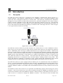
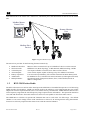
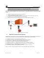
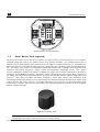
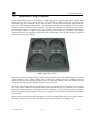
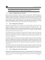
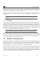
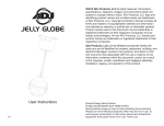
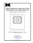
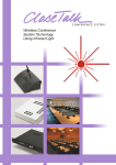
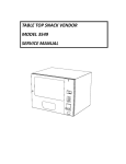
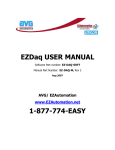
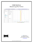
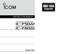
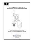
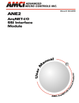
Wireless Modbus™ and 4-20mA Transceiver Model RXT-320 Operator’s Installation and Instruction Manual DETCON, Inc. 4055 Technology Forest Blvd., The Woodlands, Texas 77381 Ph.281.367.4100 / Fax 281.298.2868 www.detcon.com August 2, 2012 • Document # 3588 • Revision 2.1 RXT-320 Wireless Modbus™ Page intentionally blank Shipping Address: 4055 Technology Forest Blvd., The Woodlands Texas 77381 Mailing Address: P.O. Box 8067, The Woodlands Texas 77387-8067 Phone: 888.367.4286, 281.367.4100 • Fax: 281.292.2860 • www.detcon.com • [email protected] RXT-320 Wireless IM ii RXT-320 Wireless Modbus™ Table of Contents 1.0 Introduction ........................................................................................................................................ 1 1.1 Description...................................................................................................................................... 1 1.2 RXT-320 Wireless Radio................................................................................................................. 2 1.3 Model 100 Terminal Board (Optional) ............................................................................................. 3 1.4 Smart Battery Pack (Optional) ......................................................................................................... 4 1.5 Quad Battery Charger (Optional) ..................................................................................................... 5 1.6 Solar Panel (Optional) ..................................................................................................................... 6 2.0 Installation .......................................................................................................................................... 6 2.1 Guidelines for Safe Use ................................................................................................................... 6 2.2 Mounting......................................................................................................................................... 7 2.2.1 Remote Mounting..................................................................................................................... 8 2.3 Wiring Connections / Functions..................................................................................................... 12 2.3.1 VDC Power & VDC Return.................................................................................................... 12 2.3.2 Modbus™ A & B.................................................................................................................... 13 2.3.3 Alarm 0-3............................................................................................................................... 13 2.3.4 4-20mA A & B........................................................................................................................ 14 2.3.5 Serial Clock & Serial Data Line............................................................................................. 15 2.3.6 Programming Data, Clock & Reset ........................................................................................ 15 2.4 Model 100 Terminal Board Settings............................................................................................... 15 3.0 Operation and Configuration........................................................................................................... 16 3.1 Transparent Mode.......................................................................................................................... 16 3.2 Master Configuration with Controller ............................................................................................ 17 3.3 Slave Configuration with Sensor.................................................................................................... 17 3.4 Slave Configuration with Alarm Station......................................................................................... 17 3.5 Sleep Mode ................................................................................................................................... 18 4.0 Modbus Communications................................................................................................................. 18 4.1 General Modbus™ Description...................................................................................................... 19 4.1.1 Modbus™ Exceptions ............................................................................................................ 19 4.1.2 Modbus™ Broadcast Requests............................................................................................... 20 4.2 Modbus™ Register Map & Description ......................................................................................... 20 4.2.1 Register – Detcon Type .......................................................................................................... 21 4.2.2 Register – Alarm Outputs....................................................................................................... 21 4.2.3 Register – 4-20mA Reading.................................................................................................... 22 4.2.4 Register – Battery Info ........................................................................................................... 22 4.2.5 Register – uC Version ............................................................................................................ 22 4.2.6 Register – Sleep Time............................................................................................................. 22 4.2.7 Register – Control.................................................................................................................. 23 4.2.8 Register – Status .................................................................................................................... 23 4.2.9 Register – Address Switch ...................................................................................................... 23 4.2.10 Register – Timestamp............................................................................................................. 24 5.0 Troubleshooting Guide ..................................................................................................................... 24 6.0 Warranty........................................................................................................................................... 24 7.0 Specifications .................................................................................................................................... 25 7.1 Spare Parts .................................................................................................................................... 26 7.2 Revision Log ................................................................................................................................. 27 RXT-320 Wireless IM iii RXT-320 Wireless Modbus™ Table of Figures Figure 1 RXT-320 Wireless Transceiver Assembly...................................................................................... 1 Figure 2 Typical Wireless Layout ................................................................................................................ 2 Figure 3 Mesh Network Topology .............................................................................................................. 3 Figure 4 Model 100 Terminal Board............................................................................................................ 4 Figure 5 Smart Battery Pack ........................................................................................................................ 4 Figure 6 Quad Battery Charger .................................................................................................................... 5 Figure 7 Solar Panel .................................................................................................................................... 6 Figure 8 RXT-320 Approval Label ............................................................................................................. 6 Figure 9 RXT-320 Wireless Transceiver w/Battery Assembly and Mounting Dimensions........................... 8 Figure 10 RXT-320 Wireless Transceiver Remote Mounting ...................................................................... 9 Figure 11 Wiring Diagram for Remote RXT-320 Transceiver Mounting...................................................... 10 Figure 12 Internal Alarm Output Circuit ..................................................................................................... 14 Figure 13 Up to two Sensors using two 4-20mA Interfaces ......................................................................... 14 Figure 14 Model 100 Terminal Board Rotary Switches................................................................................ 15 Figure 16 Modbus™ Frame Format............................................................................................................. 19 List of Tables Table 1 Extension Cable Wire Identification................................................................................................ 12 Table 2 RXT-320 Transceiver Wire Identification ....................................................................................... 12 Table 3 Wire Gauge vs. Distance................................................................................................................. 13 Table 4 Model 100 Terminal Board Jumper Settings.................................................................................... 15 Table 5 RXT-320 Addressing and Operational Modes ................................................................................. 16 Table 6 Exception Codes ............................................................................................................................. 19 Table 7 RXT-320 Register Map................................................................................................................... 21 Table 8 RXT-320 Secondary Alarm Output Register Map ........................................................................... 21 RXT-320 Wireless IM iv RXT-320 Wireless Modbus™ 1.0 1.1 Introduction Description The RXT-320 wireless transceiver is designed to take Modbus™ communication between devices to a wireless platform. The transceiver connects directly to a Modbus™ device and transfers Modbus™ data to/from the device through the transceiver’s wireless radio. The transceiver broadcasts this information throughout a wireless network of other RXT-320 transceivers connected to Modbus™ devices thus creating a seamless network of Modbus™ devices that need not be physically connected in any way. The RXT-320 transceiver can be mounted to a J-Box/condulet with an optional Model 100 Terminal Board that allows for power, data connections and addressing enabling it to interface with a wide range of devices. Refer to Figure 1 for a typical wireless transceiver assembly. RXT-320 Wireless Transceiver J-Box w/ Model 100 Terminal Board NPT T-Outlet Box w/Drain - + TP1 WIR ELES S J1 Extern al DC Po we r In 7-3 0VD C mA RXT-32 0 Transce ive r W/ W/ BU BK BR W BK R J6 J5 1 WB WA SB Spare Modb us J7 2 3 Sma rt Ba tte ry Pa ck 3 4 5 6 7 R XT Pro g Interface J3 BK W W/ W/ W/V BU GN + J4 R SEN SOR/ HMI J8 TP2 1 2 RXT Pro gram ming Po rt 3 4" - SA L oop Powe red LED D isp lay BU GN Sla ve De vice/ Ma ste r Con tro ll er/ Rem ote Mon itor J2 Figure 1 RXT-320 Wireless Transceiver Assembly The RXT-320 wireless transceiver provides interfaces for 4-20mA devices as well as Modbus™ devices. There can be up to 32 devices total on a single wireless network and a transceiver can support more than one device. Additionally, there can be up to 32 RXT-320 transceivers in a single wireless network. The RXT-320 transceiver’s radio operates at 2.4GHz and conforms to non-licensed radio frequency appliance usage around the world. Wireless network integrity and security is accomplished using Direct Sequence Spread Spectrum (DSSS) wireless mesh technology. Each transceiver is capable of functioning as a router or repeater for all other RXT-320 transceivers on the network. This means that data between devices can “hop” through neighboring transceivers to communicate with each other thereby widening network access points. This unique and innovative technology is designed to create a robust network that automatically routes around congestion and line-of-sight obstacles while improving throughput as the number of devices increases. The RXT-320 transceiver comes equipped with an RS-485 port for communication with local Modbus™ devices. As with normal Modbus™ operation, there can only be one Modbus™ master and all other devices are considered as slave devices. Each device must have a unique Modbus™ address. Each transceiver is also assigned a Modbus™ address via the Model 100 Terminal Board which has two rotary switches used to set the address. The Modbus™ master unit’s transceiver is responsible for broadcasting requests and receiving slave device responses. Slave device transceivers receive these broadcasts and pass the Modbus™ information on to the slave devices attached via their local Modbus™ interface. When a response is generated by the slave device, it sends it back to its transceiver through the Modbus™ interface. The transceiver then broadcasts that RXT-320 Wireless IM Rev. 2.1 Page 1 of 27 RXT-320 Wireless Modbus™ information back to the master unit’s transceiver, which then places that information on the bus for the master unit. Modbus Master Control Unit Remote Monitor Unit Model X40-N4X Muiti-Channel Gas Detection Control System Modbus Slave Devices detcon inc. d etcon inc. MODEL IR-700 P GM1 PGM 2 Z ERO SP A N H 2 S S ensor Figure 2 Typical Wireless Layout The transceiver provides for the following features/connectivity: 1.2 Modbus™ Interface: Wireless Radio: 4-20mA Inputs: Alarm Outputs: Battery Operation: Addressable: Multiple Modes: Master or Slave connection for up to 32 Modbus™ devices on the network IEEE 802.15.4, Mesh Topology, 16 RF channels, DSSS encoding, 2.4GHz Two inputs available to connect two 4-20mA sensors/devices 4 low current outputs capable of driving relays for audible/visual alarms Low Power Sleep and battery life available from Detcon Smart Battery Pack For Modbus™ access to RXT-320 control and status (set through term board) Operational mode (Transparent, Master, Slave, Alarm Station) based on address configuration RXT-320 Wireless Radio The RXT-320 transceivers utilize radios based upon the IEEE 802.15.4 standard that operate at 2.4 GHz using DSSS encoding for robustness. DSSS was initially used by the military to resist jamming but later was widely adopted for wireless implementations since it was robust in noisy environments. DSSS transmits data across a wider frequency range than the actual frequency range required for the information. This operation minimizes cross talk and interference from other transceivers and is less susceptible to noise from other sources. The IEEE 802.15.4 defines 16 separate RF Channels that can be used in the 2.4 GHz range. The default channel is 1 but can be change if there is RF interference or if there is an existing network using that channel. Transceivers will only respond to other transceivers with the same RF Channel. RXT-320 Wireless IM Rev. 2.1 Page 2 of 27 RXT-320 Wireless Modbus™ NOTE: If there are multiple Modbus™ networks in the same vicinity each system must reside on a different RF Channel to keep data from one appearing on the other. The 802.15.4 standard also implements a mesh network allowing any RXT-320 transceiver to relay or repeat data between adjacent neighbors. This makes the network very robust and provides the following immediate benefits: Allows re-routing of data in case of loss of a transceiver Allows re-routing around wireless obstacles Longer distances between transceivers because data can “hop” from one transceiver to the next Included in sensor, controller and alarm station transceivers RXT-320 transceivers can be deployed with less concern about physical location Figure 3 Mesh Network Topology 1.3 Model 100 Terminal Board (Optional) The RXT-320 wireless transceiver can be ordered with an optional Model 100 Terminal Board mounted in a condulet/J-Box (See Figure 4). The terminal board includes connector plugs for the following: J1 6-Pin Phoenix Connector – RXT-320 Wireless Transceiver J2 5-Pin Phoenix Connector – Slave Device/Master Controller/Remote Monitor J3 6-Pin Connector – RXT Programming Port (Detcon Factory use only) J4 3-Pin Phoenix Connector – Model 100 Loop Powered LED display J5 3-Pin Phoenix Connector – 7-30VDC External power source or 24VDC Solar Panel J6 8-Pin Beau Connector – 12VDC Battery Power (Use only Detcon’s Smart Battery Pack) J7 3-Pin Phoenix Connector – Spare Modbus™ Connection J8 3-Pin Phoenix Connector – RXT Programming Interface to Wireless Transceiver Refer to section 2.4 for more information about the setup of the Model 100 Terminal Board. RXT-320 Wireless IM Rev. 2.1 Page 3 of 27 RXT-320 Wireless Modbus™ MA GND PWR B J6 SW1 24V B A J4 24V A AIN2 J7 J1 GND POWER IN (SOLAR) GND W/V W/BU W/GN W/BN J2 SW2 24V A GND WIRELESS PROGRAM J8 MODBUS OUT (WIRELESS) B W/BK AIN1 WIRELESS SENSOR MODBUS IN L9 SP2 SP1 SDA SCL PWR TERM PROGRAM GND J5 JP1 DISPLAY Figure 4 Model 100 Terminal Board 1.4 Smart Battery Pack (Optional) The RXT-320 transceiver can also be powered by an optional battery pack that enables it to be remotely mounted without the need for any cables because of its wireless operation. The available battery pack is Detcon’s plug-in Smart Battery Pack which provides an output of 12VDC (See Figure 5). If installed, the RXT-320 transceiver will detect the battery and will continuously query the battery pack for remaining battery life. The battery pack consists of rechargeable Lithium-Ion batteries and is equipped with integrated safety electronics that include fuel gauge, voltage, current and temperature monitoring circuits. This “smart” circuitry continuously monitors the battery’s condition and reports critical status information to the wireless transceiver via the Modbus™ registers. The battery pack is designed to plug onto an 8-pin Beau connector on the Model 100 Terminal Board and should not be exposed to outside elements without being housed and protected. Only Detcon products specifically designed to utilize these battery packs should be used. Operating periods before recharge will vary based on devices attached along with the transceiver and the usage of those devices, but can be as long as 2-3 months and battery life can be up to 5 years before battery pack replacement is required. Improper use of the battery pack may be hazardous to personnel or the environment and will void the warranty. Figure 5 Smart Battery Pack NOTE: The RXT-320 wireless transceiver can also be powered by a customer provided external DC power source. Refer to section 2.3.1 for more details. RXT-320 Wireless IM Rev. 2.1 Page 4 of 27 RXT-320 Wireless Modbus™ 1.5 Quad Battery Charger (Optional) Detcon’s Smart Battery Pack can be charged as needed using Detcon’s optional Quad Battery Charger which can charge up to four battery packs at one time. The Quad Battery Charger comes with a plug-in AC/DC adapter that plugs into a standard 120VAC outlet for power. The DC end of the adapter plugs into the DC power jack of the charger providing 24VDC. The Quad Battery Charger has four charging ports, each with 8pin Beau connectors for battery pack connection. The ports and connectors are keyed to prevent incorrect positioning and connection. Each port has its own “FAULT” LED indicator and “CHARGE” LED indicator and will display either a red light or green light depending on the status of each battery being charged. Charging times will vary depending on the charge state of each battery pack, but a full charge of a depleted battery pack can take up to 24 hours. Figure 6 Quad Battery Charger When first powered on and with no battery packs connected to the charger, all the LED indicators on the Quad Charger should be green. When a battery pack is seated into a charging port, the “CHARGE” LED will change from green to red indicating the battery pack is not sufficiently charged. Once fully charged, the LED will change from red to green and the battery pack is ready to be used. The “Fault” LED should remain green indicating that there are no problems with the battery pack or charging port. If the “Fault” LED turns red with the battery pack connected, then there is a problem or issue with the battery pack and it should not be used and be removed immediately. If the “Fault” LED turns red without a battery pack connected to the charge port, then there is a problem or issue with the port and that port should no longer be used. Battery packs can remain connected to the charger even after a full charge indication (Green “Charge” LED) is shown due to the protection circuitry of the battery pack which prevents any overcharging issues. RXT-320 Wireless IM Rev. 2.1 Page 5 of 27 RXT-320 Wireless Modbus™ 1.6 Solar Panel (Optional) Detcon also offers an optional solar panel to be used in conjunction with the Smart Battery Pack. It provides 24VDC output and connects to the J5 connector of the Model 100 Terminal Board. This option enables continuous operation of the wireless transceiver and charging of the battery pack eliminating the need for external recharging. It is an ideal choice for virtually any area with sufficient daily average sunlight. Since the solar panel is considered and external power supply, a special conduit installation will be required. If the optional solar panel is installed, consideration should be given to position the panel where the most sunlight is available. The solar panel can be mounted remotely to allow for maximum sunlight exposure. If necessary, a sunshade can be used for the wireless transceiver assembly to help reduce its operating temperature. Figure 7 Solar Panel 2.0 2.1 Installation Guidelines for Safe Use 1. Install unit only in areas with classifications matching with those described on the approval label. Follow all warnings listed on the label. Figure 8 RXT-320 Approval Label 2. Do not use in areas containing air saturation levels of Acetic Acid, Acetone, Ammonium Hydroxide, Fuel C, Diethyl Ether, Ethyl Acetate, Ethylene Dichloride, Furfural, N-Hexane, MEK, Methanol, 2Nitropropane, or Toluene. 3. Ensure that the transceiver is properly threaded into a suitable explosion-proof rated junction box with a female ¾” NPT threaded connection. The sensor should be threaded up at least 5 full turns until tight. Avoid use of Teflon Tape, or any type of non-conductive pipe thread coating on the NPT threaded connection. RXT-320 Wireless IM Rev. 2.1 Page 6 of 27 RXT-320 Wireless Modbus™ 4. A good ground connection should be verified between the sensor’s metal enclosure and the junction box. If a good ground connection is not made, the sensor can be grounded to the junction box using the sensor’s external ground lug. Also verify a good ground connection between the junction box and earth ground. 5. Proper precautions should be taken during installation and maintenance to avoid the build-up of static charge on the plastic weather-guard of the transceiver. 6. Do not substitute components that are not authorized by the scope of the safety approval. This may impair the intrinsic safety rating. 7. Do not operate the unit outside of the stated operating temperature limits. 8. Do not operate the unit outside the stated operating limits for voltage supply. 9. The sensor power supply common (black wire) must be referenced to the metal enclosure body (ground) during installation. 10. These units are designed to meet EN60079-0, EN60079-1, EN60079-11, UL913 7th Ed., and CSA C22.2 No.157-92. 11. These units are designed have a maximum safe location voltage of Um=30V. 12. These units pass dielectric strength of 500VRMS between circuit and enclosure for a minimum of 1 minute at a maximum test current of 5mA. 2.2 Mounting The RXT-320 wireless transceiver should be vertically oriented and mounted to an explosion-proof enclosure or junction box. The J-Box contains the optional Model 100 Terminal Board. If a battery pack is used, Detcon’s custom J-Box is needed to accommodate both the terminal board and the battery pack plus a T-Outlet box with a drain is required (See Figure 9). The RXT-320 wireless transceiver assembly is typically mounted on a wall or pole. Obstacles between RXT transceivers can impact RF line-of-sight and may result in communication problems. Each transceiver should be in view of at least one other transceiver. In some cases, it may be necessary to extend and elevate the RXT transceiver away from the J-Box/device assembly. Refer to section 2.2.1 for such remote mounting applications Detcon offers an optional mounting plate that can be used for mounting the wireless transceiver assembly on a wall or pole. If ordered with this option, secure the wireless transceiver assembly to the mounting plate using two of the four 3/8” diameter holes located on the top face of the mounting plate (If not already done so from the factory). The whole assembly can now be mounted on a secure wall using the four 7/16” diameter holes located on the base of the mounting plate (See Figure 9). The assembly can also be mounted to a pole with two U-Bolts secured through the 7/16” holes on the base. NOTE: If wall mounting without the mounting plate, make sure to use at least 0.5” spacers underneath the J-Box’s 1/4” mounting holes to move the wireless transceiver assembly away from the wall and allow clearance to the transceiver. RXT-320 Wireless IM Rev. 2.1 Page 7 of 27 RXT-320 Wireless Modbus™ Wall (or other mounting surface ) 10" Typ. RXT Series Wireless Transceiver Detcon Mounting Plate (Optional ) 7 16" 3.5" mounting holes x4 15.7" 6.1" 3 4" NPT Ports 5.5" 7.135" 3 8" T-Outlet Box w/Drain mounting holes x4 5" 8" 1 4" 8-32 tapped ground point mounting holes x2 Custom Aluminum J-Box (For Battery Option ) 7" 2.5" Figure 9 RXT-320 Wireless Transceiver w/Battery Assembly and Mounting Dimensions 2.2.1 Remote Mounting The RXT-320 wireless transceiver is normally connected directly to the J-Box containing the battery/terminal board assembly. In situations where RF line-of-sight is diminished by obstructions, it may be necessary to remotely mount the wireless transceiver away from this J-Box. Remote separation distances of up to 15 feet are possible with the recommended cable. Such an installation will require an additional J-Box which connects to the separated transceiver and houses Detcon’s 12-position terminal board plus additional hardware (See Figure 10). RXT-320 Wireless IM Rev. 2.1 Page 8 of 27 RXT-320 Wireless Modbus™ Remote RXT-320 Wireless Transceiver Remote J-Box w/ 8-Position Terminal Board Remote 34" NPT T-Outlet Box w/Drain Power, Modbus & I²C Extension Cable to/from Remote RXT Transceiver Up to 15' Length 3 4" NPT Cord Connectors (Cable Glands) Required J-Box w/ Model 100 Terminal Board WIRELESS J1 External DC P ower In 7-30VDC mA - + TP1 NPT T-Outlet Box w/Drain RXT-320 Transceiver W/ W/ BU BK B R W BK R J6 J5 1 WB WA SB Spare ModBus J7 2 3 Smart Battery Pack J3 BK W RX T Prog Interface W/ W/ W/V B U GN + J4 R SENSOR/ HMI J8 TP2 1 2 3 4 5 6 7 RXT Prog Port (Detcon Use Onl y ) 3 4" - SA Loop Powered LED Display BU GN Sl ave Devi ce/ Master Controller/ Remote Moni tor J2 Figure 10 RXT-320 Wireless Transceiver Remote Mounting A custom extension cable needs to be built per Figure 11 to interface the remote transceiver to the Model 100 Terminal Board. The recommended cable for remote transceiver separation is Belden 1421A (24AWG shielded twisted pair, 4 pairs w/drain wire). NOTE: It is highly recommended to install the extension cable inside rigid metal conduit to eliminate potential EMI and RFI interference and to maintain a Class I Division I rating. NOTE: Color coding of the cable will no longer match the color coding on the Model 100 Terminal Board for the J1 connector. NOTE: Programming of RXT transceiver from the Model 100 Terminal Board will be disabled. RXT-320 Wireless IM Rev. 2.1 Page 9 of 27 RXT-320 Wireless Modbus™ RXT-320 TRANCEIVER WIRING RED (POWER) BLACK (GND) RED (POWER) BLACK (GND) BLUE (MODBUS A) WHITE (MODBUS B) BLUE (MODBUS A) WHITE (MODBUS B) WHITE (MODBUS B) BLUE (MODBUS A) BLACK-GND RED (POWER) 700-Series Transient Protection PCA MA GND PWR B AIN2 J6 SW1 24V B A 24V J4 GND A J7 J1 MODEL 100 TERMINAL BOARD POWER IN (SOLAR) GND W/BU W/V W/BN W/GN J2 SW2 24V A B WIRELESS PROGRAM J8 MODBUS OUT (WIRELESS) GND W/BK AIN1 WIRELESS SENSOR MODBUS IN SP2 SP1 SDA SCL PWR L9 GND J5 TERM PROGRAM JP1 DISPLAY Figure 11 Wiring Diagram for Remote RXT-320 Transceiver Mounting RXT-320 Wireless IM Rev. 2.1 Page 10 of 27 RXT-320 Wireless Modbus™ Remote Mounting Steps 1. Remove the J-Box cover of the RXT-320 wireless transceiver assembly. 2. If the wireless transceiver assembly has the Smart Battery Pack, unplug the battery pack from the terminal board by pulling the battery pack out of the junction box. 3. Identify the J1 6-pin phoenix connector and the J8 3-pin phoenix connector on the Model 100 Terminal Board and disconnect from the board. Remove all transceiver wire connections from the connectors. Reconnect the 3-pin connector to its corresponding place and save the 6-pin connector for step 13. 4. Use a wrench at the bottom section of the RXT transceiver and unthread the RXT until it can be removed. 5. Feed the RXT transceiver wires through the ¾” NPT hole of the remote T-Outlet box connected to the remote J-Box and thread the transceiver into the remote T-Outlet box until tight. 6. Remove all 6 of the 4-pin phoenix connectors from the 12-position terminal board in the remote J-Box and connect the RXT transceiver wires to 3 of the phoenix connectors per the wiring diagram in Figure 11. Reference Table 2 RXT-320 Transceiver Wire Identification for color code identification. NOTE: Wires that are not used should be individually capped off and secured out of the way in the T-Outlet box so that they are not exposed to any active components, power, or ground. 7. Reconnect these 3 phoenix connectors to their corresponding places back on the 12-position terminal board. 8. Measure out the cable to be used for the extension cable to be no more than 15 feet long. Feed one end of the cable through a ¾” NPT cord connector (cable gland) and then into the ¾” NPT hole located on the bottom of the remote J-Box. 9. Connect the cable wires of the extension cable to the remaining three 4-pin phoenix connectors from step 6 per the wiring diagram in Figure 11. Reference Table 1 Extension Cable Wire Identification for color code identification. 10. Reconnect these 3 remaining phoenix connectors to their corresponding places back on the 12-position terminal board and thread the ¾” NPT cord connector to the bottom of the remote J-Box. 11. Install the J-Box cover of the remote J-Box. 12. Feed the other end of the cable through another ¾” NPT cord connector and then into the ¾” NPT hole of the T-Outlet box connected to the J-Box housing the Model 100 Terminal Board. 13. Connect the cable wires to the 6-pin phoenix connector from step 3 per the wiring diagram in Figure 11. Reference Table 1 Extension Cable Wire Identification for color code identification. 14. Reconnect the 6-pin phoenix connector back to J1 of the Model 100 Terminal Board and thread the ¾” NPT cord connector to the T-Outlet box. NOTE: Color coding of the cable will no longer match the color coding on the Model 100 Terminal Board for the J1 connector. RXT-320 Wireless IM Rev. 2.1 Page 11 of 27 RXT-320 Wireless Modbus™ NOTE: Programming of RXT transceiver from the Model 100 Terminal Board will be disabled. 15. Plug battery pack back in place and reinstall the J-Box cover from step 1. Table 1 Extension Cable Wire Identification Function VDC Power (+) VDC Return (-) Modbus A (+) Modbus B (-) Serial Clock (SCL) Serial Data Line (SDA) Common Ground Common Ground Drain Wire 2.3 Color Reference Orange/White Green/White Blue/White White/Blue White/Green White/Brown White/Orange Brown/White Bare (No Color) Wiring Connections / Functions Dependant upon use and function, the RXT-320 wireless transceiver can be wired in different ways to different devices. It is important to insure that the wiring is correct for the device to operate properly. Wire identification for the transceiver can be found in Table 2 RXT-320 Transceiver Wire Identification. Table 2 RXT-320 Transceiver Wire Identification Function VDC Power (+) VDC Return (-) Modbus™ A (+) Modbus™ B (-) Alarm 0 Alarm 1 Alarm 2 Alarm 3 4-20mA A 4-20mA B Serial Clock (SCL) Serial Data Line Data (SDA) Programming Data Programming Clock Programming Reset 2.3.1 Color Reference Red Black Blue White Brown Orange Violet Gray Green Yellow White/Black White/Brown White/Green White/Blue White/Violet VDC Power & VDC Return All RXT-320 wireless transceivers need to have DC power applied to the transceiver’s red (VDC power) and black (VDC return) wires. The power requirements for the transceiver are such that the DC voltage input range is 7 to 30 volts. This power will normally be supplied by the device the transceiver is connected to, but can come from alternate DC sources such as the optional Smart Battery Pack, solar panel or external customer supplied DC source. RXT-320 Wireless IM Rev. 2.1 Page 12 of 27 RXT-320 Wireless Modbus™ If an external power source is installed, the RXT-320 wireless transceiver requires two conductor connections for the power supply. External DC power can be customer provided with an output voltage range between 7 to 30VDC or by Detcon’s optional 24VDC solar charging panel. Both of these alternatives will provide continuous operation of the assembly and can be installed in conjunction with the optional battery pack, providing a constant power source. The external power supply will also maintain the battery pack fully charged with no overcharging issues to be concerned with due to the battery pack’s “smart” circuitry. In this configuration, external charging of the battery pack will not be necessary. In the event the external power fails, the battery pack will continue to power the wireless transceiver assembly until external power is restored or the battery is discharged. If the Model 100 Terminal Board option is not used, power to the transceiver should be directly applied to its red and black wires accordingly. If the terminal board is used, wiring designations for power are ‘+’ and ‘-’ (External DC Power In) on the J5 connector of the Model 100 Terminal Board. The maximum wire length between the transceiver assembly and a 24VDC source is shown in Table 3 Wire Gauge vs. Distance. The maximum wire size for termination in the J-Box is 14 AWG. Table 3 Wire Gauge vs. Distance AWG Wire Dia. Meters Feet 22 20 18 16 14 0.723mm 0.812mm 1.024mm 1.291mm 1.628mm 700 1120 1750 2800 4480 2080 3350 5250 8400 13,440 Over-Current Protection 3A 5A 7A 10A 20A NOTE: Wiring table is based on stranded tinned copper wire and is designed to serve as a reference only. NOTE: The supply of power should be from an isolated source with over-current protection as stipulated in table. The output voltage range must be between 7-30VDC. Before applying power, make sure that all wiring is correct. Not all wires from the wireless transceiver are used in most configurations. Wires that are not used should be individually capped off and secured out of the way in the T-Outlet that mounts the transceiver to the J-Box/condulet. This prevents exposure to any active components, power or ground. 2.3.2 Modbus™ A & B The RXT-320 transceiver features a Modbus™ compatible communication port. The connections are Modbus™ A (blue wire) and Modbus™ B (white wire) and are polarity dependent. Modbus™ communication is accomplished by two wire half duplex RS-485, 9600 baud, 8 data bits, 1 stop bit, no parity, through the transceiver’s connection to the Modbus™ device. It is necessary to set a Modbus address for the RXT-320 unless operating in transparent mode. 2.3.3 Alarm 0-3 Each RXT-320 wireless transceiver provides outputs for up to four alarms (Alarm 0, Alarm 1, Alarm 2 and Alarm 3) which can drive relays on custom terminal boards provided by Detcon. There are four internal Modbus™ registers that directly control these outputs. The outputs are open drain and rated for up to 300mA at 50V (See Figure 12). They are not intended to drive alarm devices directly, but rather to drive relay coils (interposing relays) which in turn will drive a higher current output. Detcon alarm terminal boards are available that allow either AC or DC/Battery operation with the relays built onto the board. These boards RXT-320 Wireless IM Rev. 2.1 Page 13 of 27 RXT-320 Wireless Modbus™ provide a complete solution to connecting an RXT-320 to power and providing high-current relay closures. When using interposing relays, it is strongly recommended to install a transient protection diode (1N4001) across the relay coil to mitigate the voltage spike when the coil is de-energized. RXT-320 Interposing Relay Alarm Output 1N4001 Diode From RXT-320 Processor Output Relay Coil MOSFET N-CH 50V 300mA V+ 49.9K Figure 12 Internal Alarm Output Circuit NOTE: External relays used with this circuit must not exceed voltage/current requirements and must have transient protection to minimize the voltage spike when the coil is de-energized. 2.3.4 4-20mA A & B The RXT-320 supports up to two 4-20mA signal inputs (A and B) used for monitoring 4-20mA devices (See Figure 13). For the primary 4-20mA signal input, use A (green wire). For the secondary 4-20mA signal input, use B (yellow wire). The input values are continuously read and stored in two separate registers accessible through Modbus™ at the address assigned to the transceiver. Readings on a 4-20mA input are converted to representative values, for example, 4mA is read as a value of 400 and 20mA is read as a value of 2000. These inputs present a load of 162 ohms to ground so a current of 20mA will develop around 3.4V across the input and ground. This will consume a third less power versus the 250 ohm load used in other implementations. The inputs are protected for voltages up to 30V but the input reading will reach a maximum of 2048 for currents greater than 20mA. Electrically the 4-20mA interface supports 2-wire and 3-wire devices. Figure 13 Up to two Sensors using two 4-20mA Interfaces RXT-320 Wireless IM Rev. 2.1 Page 14 of 27 RXT-320 Wireless Modbus™ NOTE: The 4-20mA inputs do NOT support 4-wire implementations 2.3.5 Serial Clock & Serial Data Line This is the I2C interface for the transceiver consisting of a serial clock (SCL) and serial data line (SDA). These are used to monitor the status of the battery pack (if installed) and to read the value of the Modbus™ address switches of the Model 100 Terminal Board (if installed). 2.3.6 Programming Data, Clock & Reset These connections are used to program the RXT-320 transceiver and should be used by Detcon personnel only. 2.4 Model 100 Terminal Board Settings This section applies to transceiver assemblies that use the optional Model 100 Terminal Board. This terminal board contains a set of jumpers that must be configured properly for the board to operate properly. These jumpers are normally configured at the factory and should not be changed. Misplacement of these jumpers may cause the transceiver to become inoperative. The following table describes the jumper positions. Table 4 Model 100 Terminal Board Jumper Settings Jumper JP1 JP2 JP3 JP4 JP5 JP6 JP7 Setting 2-3 1-2 1-2 1-2 2-3 1-2 1-2 NOTE: These settings assume the RXT-320 is not being used with a Detcon Model 100 sensor. If the RXT-320 is being used with a Model 100 sensor, these jumper settings may be different. Please refer to the appropriate Model 100 manual for the correct settings. The Model 100 Terminal Board also contains two rotary switches which are used to set the Modbus™ address for the RXT-320 wireless transceiver. The address selected is a two digit hex value with the MSD (most significant digit) represented by the top rotary switch (closest to the J1 connector) and the LSD (least significant digit) represented by the bottom rotary switch (closest to the J2 connector). For example, a hex value of ‘9F’ would be represented by a ‘9’ on the top switch and an ‘F’ on the bottom switch. Figure 14 Model 100 Terminal Board Rotary Switches RXT-320 Wireless IM Rev. 2.1 Page 15 of 27 RXT-320 Wireless Modbus™ NOTE: If using a Smart Battery Pack, battery pack removal is required to access the rotary switches for Modbus™ addressing and to access the board jumpers. Assigning a Modbus™ address to the transceiver allows registers within the transceiver itself to be accessed by the master and provide additional control and status from that transceiver. Using these registers, the master controller can control alarm outputs, read the two 4-20mA inputs, read battery life or put the network to sleep to conserve battery. The address also determines the mode of operation for the transceiver. This will determine if it is attached to a master controller or if it is attached to a slave device. 3.0 Operation and Configuration The RXT-320 wireless transceiver assembly will power up as soon as power is applied. There is no external power switch to the assembly. NOTE: Before applying power, check to make sure that all the wiring connections and external devices are installed correctly. NOTE: Applying power with devices hooked up incorrectly may cause damage to the equipment. The user will need to manually configure the Modbus™ address for the RXT-320 from the Model 100 Terminal Board. If there is no Model 100 Terminal Board, the transceiver will have no address and function in transparent mode. After the transceiver has been configured and powered up, it will begin normal operation. If the unit has been configured properly, the unit will operate differently based on the address given from the terminal board which is read once every five seconds using the I2C interface. Table 5 RXT-320 Addressing and Operational Modes Modbus Address (hex) 00 F0 01-7F, 90-DF 80-8F, E0-EF F8-FF 3.1 RXT-320 Function Transparent Mode Master Slave Alarm Station Reserved per Modbus™ Transparent Mode In transparent mode, the RXT-320 wireless transceiver behaves like a wired Modbus™ device in that any data transmitted over Modbus™ will be passed on over the RF network and be broadcast to all other RXT-320’s in the wireless network and presented on their respective Modbus™ interface. The transparent mode is achieved by setting the transceiver’s Modbus™ address equal to 00h through the transceiver’s terminal board. If the Model 100 Terminal Board is not installed, the transceiver will default to an address of 00h. The transceiver will behave as neither a master nor slave and its internal RXT-320 registers can not be accessed. Any devices connected to a transceiver in transparent mode will receive all controller requests via the Modbus™ interface and a response by the device will occur only if its Modbus™ address is equal to the request address. If so, the device will respond back to the transceiver via Modbus™ which will then send the response back to the controller over the RF network. RXT-320 Wireless IM Rev. 2.1 Page 16 of 27 RXT-320 Wireless Modbus™ NOTE: Transparent mode does not support accessing the internal registers of the transceiver through Modbus™ since there is no address assigned. Consequently many features are not available such as sleep, battery status, 4-20mA inputs and alarm outputs. 3.2 Master Configuration with Controller The RXT-320 wireless transceiver can function as a master when connected to a controller by assigning it a Modbus™ address of F0h through the transceiver’s Model 100 Terminal Board. In this configuration, the controller can send out requests and receive data/status from slave devices over the wireless network through its Modbus™ interface to the transceiver. The transceiver’s local Modbus™ interface is set up to be a slave interface to the master controller which means the transceiver will act as a slave to the controller but be seen as the master globally. Requests from the controller will be received by the transceiver through the Modbus™ interface and the transceiver will transmit the request over the RF network to all RXT-320’s. If the slave device being commanded is found, a response will be generated which will be received by the master transceiver over the RF network and sent back to the controller via the local Modbus™ interface. 3.3 Slave Configuration with Sensor The RXT-320 wireless transceiver can also function as a slave when connected to a slave device (sensor) by assigning it a Modbus™ address that is not equal to F0h (controller) or 00h (transparent mode). This Modbus™ addressing will affect how the slave RXT-320 deals with the request it receives. In this configuration, the transceiver can receive requests and send out data/status over the wireless RF network. The transceiver’s local Modbus™ interface is set up to be a master interface to the slave device which means the transceiver will act as the master to the sensor attached but be seen as a slave globally. Modbus™ addressing will dictate how the transceiver deals with a request. If the Modbus™ address in the request does not equal the address assigned to the RXT-320, the transceiver simply sends along the request unchanged on to its Modbus™. It will behave similar to transparent mode. The request will be responded to if a sensor with an address equal to the address in the request is found. If so, the sensor will respond back to the transceiver via Modbus™ which will then send the response back to the controller over the RF network. If the Modbus™ address in the request equals the address assigned to the RXT-320 and does not fall within the RXT-320 internal registers, the transceiver will translate the Modbus™ address to 01h and send along the request on its Modbus™ interface with the new translated address. This translate function allows a single DM-100 sensor to be installed per each RXT-320 since all DM-100 sensors have a fixed address of 01h. If a sensor with an address of 01h is found, it will respond back to the transceiver via Modbus™. The transceiver will then translate the 01h address back to its original value and send the response back to the controller over the RF network. If the Modbus™ address in the request equals the address assigned to the RXT-320 and falls within the RXT320 internal registers, the transceiver will not translate. The transceivers RXT-320 registers will be accessible and it will respond back to the controller over the RF network without ever having put any data on the transceivers Modbus™ interface. Any sensors connected to the transceiver would never see the request. 3.4 Slave Configuration with Alarm Station Another function of the RXT-320 wireless transceiver is as an alarm output device when connected to an alarm station. Each RXT-320 provides up to four alarm outputs (Alarm 0, Alarm 1, Alarm 2 and Alarm 3) which can drive relays on custom terminal boards provided by Detcon or interposing relays provided by the customer. These outputs are not intended to drive alarm devices directly due to their low current output, but RXT-320 Wireless IM Rev. 2.1 Page 17 of 27 RXT-320 Wireless Modbus™ rather to drive relay coils which in turn will drive a higher current output. There are four RXT alarm output registers that become available when in alarm station mode. The four alarm outputs are controlled by four internal registers within the RXT-320 and can be controlled on all RXT-320 transceivers by writing to these four registers using the Modbus™ address assigned that transceiver. If the RXT-320 transceiver is assigned a Modbus™ address between (80h-8Fh) there will be a duplicate set of four registers available to control the alarm outputs. These are introduced for compatibility with some controllers. NOTE: If the transceiver is assigned a Modbus™ address between E0h-EFh on the Term board the RXT-320 will remap its address to the 80h-8Fh address respectively and function the same way. 3.5 Sleep Mode A sleep mode is available to increase the battery life of the RXT-320 transceiver assemblies that have them. Upon command from the Modbus™, all RXT-320 transceivers will turn off their wireless radios for the requested period of time. During this time there will be no communication possible with other RXT-320 transceivers. The command is given through a single Modbus™ broadcast command (Modbus™ address of 0) with the number of seconds to go to sleep. Every RXT-320 transceiver that receives this command will turn off their on-board radio and count down the seconds until it reaches zero at which time the radios will be turned back on. The controller can query the sleep timer on its own transceiver to determine how many seconds are left and can begin Modbus™ communication when it reaches zero. NOTE: Sleep mode is not supported by transceivers that are in transparent mode since no address is assigned and therefore its internal registers are not accessible through Modbus™. When the RXT-320 transceiver radio is put to sleep it will reduce the RXT-320 power consumption by about 90%. This of course does not include other devices running off of the battery, only the transceiver. Generally the controller will put the network to sleep after all devices have been polled on the network. While the network is asleep, there are no devices being read so the user will have to trade off power consumption versus the time between updating/reading a device on the network. 4.0 Modbus Communications The RXT-320 wireless transceiver incorporates an RS-485 two-wire interface for communication with various Modbus™ devices such as a control system or sensor. There can be up to 32 devices attached to an RXT-320 wireless transceiver and up to 32 RXT-320 transceivers on a single wireless network. As with normal Modbus™ operation, there can be only one Modbus™ master that polls all the other devices which are considered Modbus™ slaves. Each slave device must have a unique Modbus™ address. The Modbus™ master control unit with its transceiver is responsible for broadcasting requests and receiving slave device responses. Slave device transceivers receive these broadcasts and pass the Modbus™ requests on to the slave devices attached. When a response is generated by the slave device, its transceiver transmits the response back to the broadcasting transceiver, which then places the response on the bus back to the master control unit. Modbus™ communication is accomplished by two wire half duplex RS-485, 9600 baud, 8 data bits, 1 stop bit, no parity, through the transceiver’s connection to the Modbus™ device. RXT-320 Wireless IM Rev. 2.1 Page 18 of 27 RXT-320 Wireless Modbus™ 4.1 General Modbus™ Description The RXT-320 performs Modbus™ communication using the RTU transmission mode per the Modbus™ specification. The basic frame format for Modbus™ consists of a Modbus™ address, function code, data and CRC. Address Field Function Code Data CRC Figure 15 Modbus™ Frame Format As stated earlier, the Address Field is the unique Modbus™ address of each device for the whole system. The Function Code is the function to be performed. The Data contains read or write data and is formatted according to the function being performed. The CRC (Cyclic Redundancy Code) is used to detect errors in the frame. Frames with errors are invalid and ignored. Modbus™ transactions consist of both a request by the controller and response from the device being addressed so there are two frames transferred for every transaction. Every request is evaluated by the RXT320 to determine if it is addressed to it and whether it falls within the register address range. If these two conditions are true, the RXT-320 will then check to see if it is a valid Function Code. Function Codes supported by the RXT-320 are: Function Code 03 (03h) – Read Holding Registers Function Code 06 (06h) – Write Single Register Function Code 16 (10h) – Write Multiple Registers If an invalid function code is performed, then the RXT-320 will ignore the request by default and the controller will timeout and continue with the next transaction. 4.1.1 Modbus™ Exceptions The RXT-320 is capable of returning Modbus™ exceptions when it cannot service a Modbus™ request meant for that RXT-320. By default this is turned off since it can cause issues with some controllers that do not process Modbus™ exceptions. The following exception codes are supported and returned when Modbus™ exceptions are enabled: Table 6 Exception Codes Exception Code Name 01 Illegal Function 02 Illegal Data Address Meaning Unsupported function code. Only 03, 06 and 16 are supported. The registers being requested falls only partially within the valid RXT-320 register ranges. For example, the RXT-320 registers start at 8192. If an access is perform requesting registers 8191 to 8192 then this is an Illegal Data Address since 8191 does not fall completely within the valid register range. This would not be an exception though if register address 8190 to 8191 were used – this would be passed on to the Modbus™ interface for a local device to respond. There are other exception codes defined in Modbus™ but these are the only ones returned by the RXT-320. RXT-320 Wireless IM Rev. 2.1 Page 19 of 27 RXT-320 Wireless Modbus™ 4.1.2 Modbus™ Broadcast Requests The Modbus™ broadcast request was introduced in the RXT-320 to support commands to be executed across all RXT-320 transceivers simultaneously. More specifically this is used to place all RXT-320s in a low power sleep state to conserve battery life. If none of the RXT-320s are battery powered there is no need to issue a sleep command. According to the Modbus™ specification a broadcast request is defined as a request with the Address Field set to 0 and is used for writing only. There is no response returned as with normal Modbus™ transactions since all devices on the system are accessed at the same time. Both Function Codes 06 and 16 (writes) are supported with a broadcast request on the RXT-320. Since there is no response on the broadcast request, there is a requirement to wait for a period of time before sending out the next request. This allows all slave devices to process the command before the next request is received. This is defined as the “turnaround delay”. This turnaround delay should be approximately 150 milliseconds for broadcast requests sent to the RXT-320. Controllers in general can meet this timing because it takes longer than this to generate the next request so it may be unnecessary to make any adjustments to meet this timing. NOTE: Controllers that generate Modbus™ broadcast requests to the RXT-320 must ensure a turnaround delay of 150ms is met otherwise the next request can cause the broadcast request to be overwritten and ignored. Broadcast requests are not confined to sleep commands but can be used where any normal write command is used. Broadcast requests received by the RXT-320 are also passed on to the local Modbus™ interface to allow a controller to write to slave devices on that interface. 4.2 Modbus™ Register Map & Description When the RXT-320 is assigned a Modbus™ address, the following registers become available to the controller for access. All RXT-320 transceivers implement this register set. If the RXT-320 is configured as an Alarm Station (address = 80h-8Fh or E0h-EFh) then a secondary set of registers is made available for controlling Alarm Outputs (Table 8). Both register maps are shown below. Some registers are Read Only (R) and others are Read/Write (R/W) as shown by the Access column. This equates to specific function codes where Read is function code 03 and Write is function code 06 or 16. NOTE: A write to a Read Only register is allowed and returns a response but it does not change the value of the register. In some devices this would return an exception code. The following sections will describe each register or register set for the register maps. RXT-320 Wireless IM Rev. 2.1 Page 20 of 27 RXT-320 Wireless Modbus™ Table 7 RXT-320 Register Map Register Access 8192 R 8193 R/W 8194 R/W 8195 R/W 8196 R/W 8197 R 8198 R 8199 R 8200 R 8201 R 8202 R/W 8203 R/W 8204 R 8205 R 8206 R/W 8207 R/W 8208 8209 8210 8211 – 8270 R R R Name Detcon Type Alarm 0 Output Alarm 1 Output Alarm 2 Output Alarm 3 Output 4-20mA A 4-20mA B Battery Life Percent Battery Life Minutes uC Version Sleep Time Control Status Battery Voltage I2C Batt Read Fails I2C Switch Read Fails Timestamp Secs High Timestamp Secs Low Timestamp mSecs -- Reserved Description Detcon Register Type = 22 for RXT-320 Controls the Alarm 0 Output Controls the Alarm 1 Output Controls the Alarm 2 Output Controls the Alarm 3 Output Reading for 4-20mA Sensor Input (A) Reading for 4-20mA Sensor Input (B) Battery Life remaining in % Battery Life remaining in minutes Micro Controller Firmware Version (Major.Minor) Sleep Time in seconds RXT-320 Control register Status Battery Voltage in millivolts I2C Battery Read failure count Reserved registers I2C Rotary Switch Read failure count Time from Startup – Seconds High Time from Startup – Seconds Low Time from Startup -- Milliseconds Table 8 RXT-320 Secondary Alarm Output Register Map Register 0000 0001 0002 0003 0004 4.2.1 Access R R/W R/W R/W R/W Name Detcon Type Alarm 0 Output Alarm 1 Output Alarm 2 Output Alarm 3 Output Description Detcon Register Type = 03 for RL4 Controls the Alarm 0 Output Controls the Alarm 1 Output Controls the Alarm 2 Output Controls the Alarm 3 Output Register – Detcon Type Both register maps include this Detcon Type and is a unique identifier of the type of device and associated register map. A controller can therefore perform a search and determine what Detcon devices are present on a Modbus™ system. 4.2.2 Register – Alarm Outputs There are four registers that control the four open collector Alarm Outputs. A value of 0 written to these register will turn the Alarm Output off (not grounded). A value of 1 or non-zero value will turn the Alarm Output on (grounded). If the secondary Alarm Output registers are enabled, the registers are duplicated and writing to either set will turn on or off the Alarm Outputs. The current value of the Alarm outputs can be read at any time. The default value for all Alarm Outputs upon power up or reset is 0. RXT-320 Wireless IM Rev. 2.1 Page 21 of 27 RXT-320 Wireless Modbus™ 4.2.3 Register – 4-20mA Reading There are two 4-20mA inputs and their current value is stored in the 4-20mA A and B registers. The value of these register will range between 0 to 2048 with 0 being 0mA and 2048 being 20.48mA. Therefore a 4mA input will read 400 and a 20mA input will read 2000. Any currents above 20.48mA will remain at 2048 since this is the maximum value for this register. 4.2.4 Register – Battery Info If a Detcon battery pack is connected to the RXT-320 transceiver, there are five registers associated with information about that battery. The RXT-320 utilizes the I2C interface to read battery status and only one Detcon battery pack can be read per RXT-320. The controller can determine if a battery is present by reading the Status Register (register 8204). There are two bits in this sixteen bit register pertaining to the battery, Battery Detect – bit 6 (lowest bit is 0) and Battery Fault – bit 7. Both bits default to a value of 0. Battery Detect will be set once the first read of the battery over the I2C interface was successful. Battery Fault will be set if a battery was detected but the last read failed. Battery Fault is re-evaluated upon every read of the battery which is set to approximately every 5 seconds. Register 8206 (I2C Batt Read Fails) will increment by 4 each time there is a failure since there are 4 attempts before declaring failure. This register can be cleared by writing a 0 to it at any point. Once the battery has been detected the controller can read the battery life (registers 8199 and 8200). The battery adjusts these values based upon the average current usage. If this usage varies widely over time it will take some time to re-adjust the battery life readings. For instance an Alarm Station with no alarms will consume a very small amount of battery but when Alarms are active this will jump to a much higher level of usage. So in this case battery life may go from several weeks down to several hours. The battery life is presented in two forms, life remaining in percentage (register 8199) and life remaining in minutes (register 8200). The battery Life remaining is percentage is a value between 0 and 100 and battery life in minutes is an unsigned value between 0 and 65535. Both readings are generally necessary to provide appropriate feedback to the user. Life in minutes is the best for determining when to change the battery. For example if the user wanted to be notified a day before the battery needed to be changed, the user could set a threshold in the controller to be notified of low battery after 1440 minutes (1 day). Since 65535 is the maximum value for life remaining in minutes, this represents a maximum of 45.5 days. The battery life for an application can be much greater than this value and will remain at a reading of 65535 until it drops below this. Life in percentage was added for this reason. Percentage will track starting at 100 percent and drop down as battery life decreases. The controller can therefore use both registers, one to represent usage in percentage to present to the user and then use the life in minutes to set a threshold on when a low battery condition exists for changing the battery. 4.2.5 Register – uC Version This is set to a value based upon the version of firmware programmed into the RXT-320 microcontroller. It is stored as two byte value representing the major and minor revision numbers. So a 0113h (275 decimal) represents a major version of 01 and minor version of 13. As software is updated this will be incremented appropriately. 4.2.6 Register – Sleep Time The Sleep Time represents the amount of time in seconds the RXT-320 will be in a low power sleep state. Its main purpose is to provide a mechanism for place all RXT-320s in a system to sleep to conserve battery power. If there are no batteries used within the network of RXT-320 transceivers this register is not utilized. RXT-320 Wireless IM Rev. 2.1 Page 22 of 27 RXT-320 Wireless Modbus™ Upon power up, this register is set to 0 and the RXT-320 is not in low power mode. To place a network to sleep the controller will generate a broadcast request (Modbus™ address = 0) and do a single write (function code 06) to register 8202 with the number of seconds the network should go to sleep. During sleep there can be no access to any device on the network so the user will have to trade off sleep time versus getting device updates. Once a non-zero value is written to this register on all RXT-320s, they will begin counting down until the Sleep Time reaches zero, at which time all RXT-320s should be active again and ready for network communication. The controller can monitor the sleep time remaining by accessing Sleep Time register on the RXT-320 attached to it. The Modbus™ interface remains active, only the wireless network is placed in a low power state. The value of this register can be between 0 and 65535 which allows a maximum sleep time of 18.2 hours. Removal of power will reset Sleep Time to 0. 4.2.7 Register – Control The Control register is generally unused and should not be written to normally. Using the control register, the RXT-320 can be reset, Modbus™ exceptions can be enabled and the Alarm Outputs 2 and 3 can be used as indications of receive for Modbus™ or Wireless interfaces. Each bit in the control register can control a particular function and should be read first then modify the bits needed and written back. The default state of the register is 0. All reserved bits should always be set to a 0 when writing. The listing below shows the bit assignments. Bit 15: Bit 14: Bit 13 – 12: Bit 11: Bit 10 – 08: Bit 07: Bit 06: Bit 05 – 00: 4.2.8 Reserved (set to 0) Debug Rx Activity Status, Alarm 2 = Wireless Rx, Alarm 3 = Modbus Rx Reserved (set to 0) Modbus Exceptions Enabled Reserved (set to 0) Reset the microcontroller and wireless radio Reset the microcontroller Reserved (set to 0) Register – Status This register contains status of the RXT-320 and some of the bits have already been covered in the battery description. These default to 0 upon reset. The bit assignment and description are given below. Bit 15 – 08: Bit 07: Bit 06: Bit 05: Bit 04: Bit 03: Bit 02: Bit 01: Bit 00: 4.2.9 Reserved (set to 0) I2C Fault on last read of Modbus Address Switch (Rotary Switch on Term Board) Modbus Address Switch Detected (Always set to a 1 when address set) I2C Fault on last read of Battery Status Battery Detected Alarm Station address detected – second set of Alarm Output registers available Slave RXT-320 Master RXT-320 – controller attached to Modbus™ interface Reserved (set to 0) Register – Address Switch The rotary switch on the Model 100 Termination board provides the Modbus™ address through the I2C interface. There is both an Address Switch Detect and Fault bit defined in the status register. The rotary switch is read approximately every 5 seconds and the Fault bit is set if the last read failed. Register 8207 (I2C Switch Read Fails) will increment by 4 each time there is a failure since there are 4 attempts before declaring failure. This register can be cleared by writing a 0 to it at any point. RXT-320 Wireless IM Rev. 2.1 Page 23 of 27 RXT-320 Wireless Modbus™ 4.2.10 Register – Timestamp Three registers are utilized to maintain a timestamp that increments on the microcontroller after power up. These are all set to 0 upon power up or a microcontroller reset. The first two registers 8208 and 8209 are internally combined into a single 32 bit register and incremented each second. The last register 8210 maintains the millisecond count and will count from 0 to 999 and start over again. 5.0 Troubleshooting Guide Power Problems Probable Causes: Depleted battery/Low Charge, battery not seated properly. Recharge or replace battery. Reseat battery. Transceiver not Responding Probable Causes: Incorrect jumper settings on term board, incorrect wiring, connectors not seated properly. Verify jumper settings are properly configured. Verify transceiver wiring matches color coding on term board. Verify connectors are seated correctly and not offset. Reseat connector is necessary. Modbus™ Communication Problems Probable Causes: Incorrect Modbus™ address, incorrect rotary switch settings, incorrect wiring. Verify Modbus™ address corresponds to the appropriate function desired (Master, Slave, Transparent Mode, Alarm Station). Verify there are no duplicate Modbus™ addresses on the network. Verify Modbus™ address has been configured correctly on term board rotary switches. Verify correct polarity on Modbus™ wiring. Condensation Problems Probable Causes: Loose cover on T-Outlet box, loose cover on transceiver housing, loose NPT connections to condulet/j-box, expired condensation prevention packet. Verify cover is tight on T-Outlet box and transceiver housing. Verify all NPT connections are secure and tight. Replace condensation prevention packet. 6.0 Warranty Detcon, Inc., as the manufacturer, warrants under intended normal use each new Model RXT-320 wireless transceiver to be free from defects in material and workmanship for a period of one year from the date of shipment to the original purchaser. Should the transceiver fail to perform in accordance with published specifications within the warranty period, return to Detcon, Inc. for necessary repairs or replacement. All warranties and service policies are FOB the Detcon facility located in The Woodlands, Texas. RXT-320 Wireless IM Rev. 2.1 Page 24 of 27 RXT-320 Wireless Modbus™ 7.0 Specifications Frequency ISM 2.4GHz Range Indoor/ No Line of Sight: 1,000ft Outdoor RF Line of Sight (with external antenna): 3 Miles. Spread Spectrum Digital-Sequence Spread Spectrum (DSSS) Modulation 0-QPSK Sensitivity -102dBm (1% PER) Inputs RS-485 Modbus™ RTU (9600bps) Two 4-20mA inputs Outputs RS-485 Modbus™ RTU (9600bps) Power Input 7-30VDC Power Consumption Base RXT-320 unit: <500mW, 20 mA max at 24VDC Total Power is dependent on communication update rate between RXT-320 transceivers. Operating Temperature Range -40°C to 85°C Approvals cETLus Class 1, Division 1, Groups CD ATEX II 2 G Ex d [ib] ib IIB T6 (pending) CE Marking (pending) Dimensions 8.3” (H) x 2.4” (Dia.) Weight 30oz/850g RXT-320 Wireless IM Rev. 2.1 Page 25 of 27 RXT-320 Wireless Modbus™ 7.1 Spare Parts Spare Parts Part Number 976-000320-316 RXT-320 Wireless Transceiver Optional Accessories Part Number 897-850800-010 897-850400-010 897-850902-010 960-202200-000 800-004221-000 8522-750 899-15075 897-044400-34T 898-52310 899-07550 500-005168-100 976-000303-012 976-000304-004 500-003198-000 301-58205 RXT-320 Wireless IM NEMA 7 Aluminum Condulet Base NEMA 7 Aluminum Condulet Solid Cover NEMA 7 Tall Aluminum Condulet w/Window Cover (Required for Battery Option) Condensation prevention packet (For condulet, replace annually) Mounting Plate ¾” NPT Plug ¾” NPT x 1.5” Nipple ¾” NPT T-Outlet Box w/Aluminum Cover ½” NPT Drain ¾” NPT to ½” NPT Adapter (Required for Drain) Model 100 Terminal Board 12V Smart Battery Pack Quad Charger w/AC Adapter 12-Position Terminal Board (Remote Mounting) ¾” NPT Cord Connector (Remote Mounting) Rev. 2.1 Page 26 of 27 RXT-320 Wireless Modbus™ 7.2 Revision Log Revision 1.0 1.1 2.0 Date 05/19/10 11/12/10 04/12/11 2.1 08/02/12 RXT-320 Wireless IM Changes made Original Release. Update to table 1 Wire Identification Extensive revision and detail added to all aspects of manual. Updated board and wiring diagrams, updated spare part list Rev. 2.1 Approval LBU LBU LBU LBU Page 27 of 27