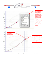
1
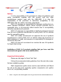
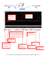
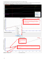
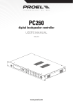
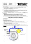
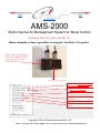
Next
Back
Click for Index.
AMS-2000
Multi-Channel Air Management System for Boost Control
SOLENOID INSTALLATION AND SET UP
Mount solenoids as close as possible to wastegates! Less than 3 ft is perfect.
Regulated CO2 / Air OR Manifold
pressure that is PRE Throttle Body
would go into this port on the
solenoid manifold
Air In
Increase
Decrease
Air out to top of wastegate
Takes the tune up from the AMS-2000 and
loads it onto your computer screen.
Takes the tuneup on your computer screen
and loads it onto the AMS-2000
Open a tune up thats been saved to your
laptop and load it onto your computer screen
Save the tune up on your computer screen
to your laptop
Download data from AMS-2000
Open a log file thats been saved on your
computer
1
Copyright © 2014, All Rights Reserved, NLR, LLC
NOTE—Target Psi is the amount applied to the waste gate and is NOT the actual Manifold Boost Psi!
Next
Back
Click for Index.
Notice:
It is the responsibility of the purchaser to follow all guidelines and
safety procedures supplied with this product and any other
manufacturers product used with the AMS-2000. It is also the
responsibility of the purchaser to determine compatibility of the
AMS-2000 with the vehicle and other components.
NLR, LLC assumes no responsibility for damages resulting from accident, improper installation, misuse, abuse, improper operation, lack of
reasonable care, or all previously stated reasons due to incompatibility
with other manufacturer’s products.
NLR, LLC assumes no responsibility or liability for damages incurred
from the use of products manufactured or sold by NLR, LLC on vehicles
used for competition racing.
NLR, LLC neither recommends nor approves the use of products
manufactured or sold by NLR, LLC on vehicles which may be driven on
public highways or roads, and assumes no responsibility for damages incurred from such use.
NLR, LLC does not recommend nor condone the use of its products
for illegal street racing.
Installation of NLR, LLC products signifies that you have read this
document and agree to the terms stated within.
Important Information:
Please see last page for Quick Tech Tips!
Follow all recommended safety guidelines from this and other manufactures installation guides.
Static suppression ignition wires must be used with this unit! Mount
the unit as far away from secondary ignition components (coil, ignition
wires, etc.) as physically possible.
2
NOTE—Target Psi is the amount applied to the waste gate and is NOT the actual Manifold Boost Psi!
Next
Back
Click for Index.
Description— The AMS-2000 is the most advanced Boost/Air Management system
available on the market. Let's get to it!
Just a few things to knowData logging is integrated into the AMS-2000 and provides the user with instant
feedback on the performance and real time operating parameters. The Data is
presented as a Graph for detailed data information. If only the main Boost channel is
used for control of a waste gate the Aux channel MAP Sensor input can be used to
log another pressure. If both channels are used for control then the logged data will
represent the real time pressure applied to each channel during operation.
Standard sensors are gm 3 bar, SSI 60 , SSI 100 , and custom configuration.
Multiple operating modes available, Time Based, Shift Based, Engine RPM,
TPS, Analog Voltage, Air Temp, Pressure, Air Fuel , MPH and Shaft RPM.
Time Based— Apply target pressure over time
Shift Based—One to six stages are available and are controlled by a Shift Input
signal. Once you change to the next gear a new timer starts. Basically a time based
platform for every gear.
Analog Based—Target pressure is controlled by a 0-5 volt analog Input signal. Gear
position or GPS as an example.
Shaft Rpm Based- This can be tied to a driveshaft sensor for driveshaft speed or
front wheel speed sensor and used for Speed based control, Turbo speed control,
Driveshaft speed control -------- Contact NLR for which turbo speed sensor to use.
Engine RPM Based- Target pressure applied based on Engine RPM(watercraft, boats, planes)
TPS Based- Target pressure based on Throttle Position ( watercraft, boats, planes)
Air Temp Based- Target pressure based off of Air temp
Pressure Based- Target pressure based off of a pressure input ( Backpressure, Manifold, etc)
Air Fuel Based- Target pressure based off of an Air Fuel Sensor input
PRO UNIT- offers ability to choose one of the control strategies and then
the rest of them become an offset to the primary you have chosen. Example:
Choose time based as the primary. If I use Engine RPM for an offset I can put 0 at 4000 rpm and
10psi at 6000 rpm the controller will add this pressure once it sees that rpm. This is perfect for
overcoming a set up that may see the gates opening at higher rpm. The rest of the offsets can also
be used at the same time as well ,producing an absolute intricate control!
3
NOTE—Target Psi is the amount applied to the waste gate and is NOT the actual Manifold Boost Psi!
Next
Back
Click for Index.
Basic Unit- You can only choose one of the control startegies. No
offsets will work with the basic unit.
Multiple control inputs, Launch, Shift, Scramble, and Reduce inputs. These control inputs can be configured through the software to be Active with either a +12 volt
or a Ground signal.
Clutch Input—When active the Launch Target psi for each channel will be applied. The Launch Target psi can be set by the user through the Options Menu. When
the Clutch Input is ON the Activation Signal is Ignored until the Launch signal is removed. i.e.—The controller will Ignore the Activation Input signal while the Clutch Input
signal is ON. An activation/timer reset option can be used with the Clutch Input, see
the Option menu settings for more details.
Shift Input—A signal applied to this input will increment the Gear Position
counter when the Activation Input is ON. The gear counter can be Reset each time a
Clutch Input signal is recognized. Normal operation is that the Gear Counter is only
Reset when the Activation signal is removed.
Scramble Input—The Scramble Input allows the user to increase or Scramble
the target psi by a programmed amount. The Scramble function will function even if the
Activation Input is OFF. The amount of Scramble increase is always added to the current target psi.
Reduce Input—The Reduce Input allows the user to decrease or Reduce the
target psi by a programmed amount. The Reduce function will function even if the Activation Input is OFF. The amount of Reduce decrease is always subtracted from the
current target psi.
Activation Input—The Activation input control the start of the timers. The
Activation input is ignored if the Clutch input is ON. The Activation input can have
a Hold-and-Wait timer that is programmed by the user. i.e.—If the user
programmed a Hold-and-Wait value of .05 second the Activation input will not turn
OFF for .05 seconds when the signal is removed.
4
NOTE—Target Psi is the amount applied to the waste gate and is NOT the actual Manifold Boost Psi!
Next
Back
Click for Index.
AMS-2000 Features:
1—Billet aluminum enclosure and all parts are specified over an extended temperature range.
2—Vibration and weather proof.
3—System software can be erased and reprogrammed by the user for future software updates.
4—User settings will remain for up to 20 years with no power applied. No back up batteries are needed.
5—Factory default program can be loaded in order to restore controller to state it was out of the
box from the factory.
6—Preconfigured or custom pressure sensor set ups available.
7—Scramble boost to apply an amount of pressure that you program to the gate, thus increasing boost
no matter where in the main program you are currently at. Think of it as an emergency boost button
(kinda like a shot of nitrous) Remove the signal and it goes back to current target psi. Can be used as a
single stage of boost
8— Reduce boost which works the opposite of scramble. It will remove a programmed amount from the
current target psi. If you spin stab a button it will reduce power instantly.
10—Multiple operating modes:
Time Based, Shift Based, Engine RPM, TPS, Analog Voltage, Air Temp, Pressure, Wideband, MPH and
Shaft RPM.
11—Dual output channels are available. The auxiliary channel may be used for live boost pressure
data viewing and data logging or control. Basically there are 2 controllers in 1 box. You can control
multiple waste gate , valves, blow offs on supercharged systems thus giving you boost control. Only
enabled in PRO UNIT
12—Integrated data logger with 512k memory. Graph view of logged data.
13—Graph view of programmed settings.
14—Most inputs can be configured for + 12volt or ground activation.
15—All inputs have input protection diodes. All outputs have integrated noise suppression devices
to clamp fly back voltage from solenoids.
16—Outputs short circuit protected and over current protected( 7 amp Maximum)
17—Reverse battery protection.
5
NOTE—Target Psi is the amount applied to the waste gate and is NOT the actual Manifold Boost Psi!
Next
Back
Click for Index.
Table of Contents:
Notice and Important Information
Important information and Cautions
Page 2
AMS-2000 Description
General Overview and Operation
Page 3, 4
AMS-2000 Features
AMS-2000 Features
Page 5
Software,
Selecting MAP Sensor
Setting Launch Psi, Boost and Aux Channels
Page 7
Page 7, 8
Software,
Setting Scramble and Reduce Psi, Boost Channel
Setting Activation Hold and Clutch Reset Style
Page 8
Page 9
Software,
Setting Launch, Shift, Scramble, and Reduce polarity
6
Page 10
Page 10, 11
Software,
Setting Tach, TPS, Air Temp, Air
Fuel, MPH or Shaft calibrations
Page 11
Page 12
Software,
Setting input polarity and selecting and saving profiles
Boost Channel and Aux graph adjustment
Data Overlay on Graph
Page 12
Page 13, 14, 15
Page 16
Software
Data Overlay on Graph
Page 17
DATA Menu
Viewing Logged Data ,setting parameters
Data View page explanation
Page 18
Page 19
Installation Instructions
Wiring
Plumbing and ECU Mounting
Page 20
Page 21
Live Data Screen
Page 22
Software and Firmware updating
Page 23
Upgrading from Basic to Pro
Page 24
Warranty Information
Warranty
Quick Tech Tips
Tech Tips
Page 25
Manifold Pressure Control Mode
Page 26
Manifold Pressure Limitation
Page 29
Page 25
Next
Back
Click for Index.
Selecting Pressure Sensor
Connect the desired sensor as outlined in the Installation section and then follow the
instructions below.
Warning—Make sure the Selected Sensor matches the one that is installed. All Sensors if
connected will re-calibrate. If the wrong one is selected the pressure readings will NOT be
correct!
Click drop down and select
sensor
Selecting Manifold Pressure Sensor
Setting Launch Psi, Boost and Aux Channels
The Launch settings will be applied when the Clutch input is ON. Even if the Activation input
is ON. The target psi will be overridden by the Launch Psi setting. Scramble and Reduce Inputs will
function as normal and Add or Subtract from the Launch setting.
If the Clutch Reset Option is ON all Timers will Reset and the Shift Counter will
return to 1st Gear.
Continued on Next Page.
7
NOTE—Target Psi is the amount applied to the waste gate and is NOT the actual Manifold Boost Psi!
DO NOT FORGET TO HIT (FILE AND THEN SAVE USER DATA TO AMS-2000 OR IT WILL
NOT BE SAVED TO THE ECU.)
Next
Back
Click for Index.
Setting Launch Psi, Boost and Aux Channels, Continued...
set launch pressure here
Setting Scramble and Reduce Psi, Boost Channel
When the Scramble Input is ON, the Boost Channel Target Psi will be Increased by the Scramble
setting. This function is available in ALL Modes of operation, including Launch Mode (clutch input ON). The
Aux Channel is NOT affected by this setting. When the Reduce Input is ON, the Boost Channel Target Psi
will be Decreased by the Reduce setting. This function is available in ALL Modes of operation, including
Launch Mode (clutch input ON). The Aux Channel is NOT affected by this setting.
To adjust reduce just click
this tab
To modify just double click to
add a edit point and move it
around to create your curve.
DO NOT FORGET TO HIT (FILE AND THEN SAVE USER DATA TO AMS-2000 OR IT WILL
NOT BE SAVED TO THE ECU.)
8
Next
Back
Click for Index.
Setting Activation, Activation Hold and Clutch Reset Style
1.
The Activation Hold function when Programmed with a value greater than 0.00 will Delay the
release of the Activation Input. i.e.—If the user is using a Wide Open Throttle switch to control the Activation. A Delay could be used to keep the system from re-setting if the throttle is lifted for a short period
of time.
If the Clutch Reset Style is ON all Timers and Both channels will be RESET if the Clutch Input is
2.
Active (even if the Activation Signal is ON). If the Clutch Reset Style is OFF the system will only RESET
when the Activation signal is removed.
1.
2.
There are many thresholds that can be used to start the control progress.The AMS1000 used a 12 volt signal. The AMS2000 uses a ground
or 12 volt but can also use any of the following . In the picture below I have selected TPS with a threshold of 30 percent. The master activation
switch needs to be on but nothing will happen until I pass 30 percent TPS. If I enable ENGINE RPM (5000) it will need to pass 30 percent
TPS and 5000 rpm before it starts to control. If any threshold drops below its value control will stop.
9
NOTE—Target Psi is the amount applied to the waste gate and is NOT the actual Manifold Boost Psi!
DO NOT FORGET TO HIT (FILE AND THEN SAVE USER DATA TO AMS-2000 OR IT
WILL NOT BE SAVED TO THE ECU.)
Next
Back
Click for Index.
Setting Input Polarity , Selecting and Saving Profiles.
The Launch, Shift, Scramble, and Reduce inputs can be configured for +12 volt or Ground activation. This way existing wiring and/or switch setups can be used.
The Profiles are MAPS that can be instantly switched when offline by the selector switch. This gives
instant on the fly tune capability for track conditions.
Modify a profile and then save it to a position.Once a map has been built just right
click on the profile tab and options will pop up . Select copy to profile .It will copy
the map to this position. Make sure you click File in the upper left and hit SEND
USER DATA TO AMS-2000 or it will not be saved to the ecu. To view a profile just
click the drop down menu next to Select Current Profile and choose which you
want to see. It will load this set up instantly. I always start on profile one and save
tune ups to other profiles.
To set input polarity just click the the button next to whichever you want to select. Make sure to
Save USER DATA TO AMS-2000.
DO NOT FORGET TO HIT (FILE AND THEN SAVE USER DATA TO AMS-2000 OR IT WILL
NOT BE SAVED TO THE ECU.)
Continued on Next Page.
10
NOTE—Target Psi is the amount applied to the waste gate and is NOT the actual Manifold Boost Psi!
Next
Back
Setting Tach, TPS, Air Temp, Air Fuel, MPH or Shaft calibrations-
Click on the tab and
then adjust the
parameters that
open up. Make sure
you hit file and then
save data file to
AMS-2000.
off throttle then hit use current volt.
Go full throttle and then hit current
volt.
choose which air temp
sensor
Set the voltage and related
air fuel ratio here for both
channels. This info will be in
the instructions from your air
fuel ratio sensors.
11
NOTE—Target Psi is the amount applied to the waste gate and is NOT the actual Manifold Boost Psi!
DO NOT FORGET TO HIT (FILE AND THEN SAVE USER DATA TO AMS-2000 OR IT WILL
NOT BE SAVED TO THE ECU.)
Next
Back
Click for Index.
choose this for mph and then use
calibration wizard to manual set up.
You will need a sensor on a non
driven wheel
choose this for driveshaft
choose this for
turbo speed
Selecting Boost Channel Control Mode
Multiple operating modes are available. Time based, Shift based, Analog Voltage,
Engine RPM, Wideband, Pressure, Air Temp, TPS, MPH and Shaft RPM..
Whatever you choose for your primary control mode the rest become offsets to that
channel giving you the most advanced capability available anywhere. This is only available with
the PRO UNIT.
Just click button next to the style you are
looking to run! It will turn blue when it is
selected. Make sure you SAVE USER DATA
TO AMS2000 or it will not save to the ECU.
DO NOT FORGET TO HIT (FILE AND THEN SAVE USER DATA TO
AMS-2000 OR IT WILL NOT BE SAVED TO THE ECU.)
12
NOTE—Target Psi is the amount applied to the waste gate and is NOT the actual Manifold Boost Psi!
Next
Back
Click for Index.
Boost Channel and Aux Channel Graph Adjustment
After Choosing what type of control strategy you want to use click on the Boost Channel tab next
to the configure tab. Next click on the tab of the control strategy you chose. You will notice that
the graph starts at 0-to max pressure on the left side and your strategy along the bottom. ****If
you are on the wrong table the left side would be 0 and then it will go up and also down as it is an
offset table. Example below.
To adjust simply double click the mouse to set a point. The chosen point will always have a
square around it indicating it is the one being moved. Hold the mouse button down to move it
around . Release the button to place it.
Coarse Movement- hold shift key and use arrow
keys.
Fine movement- Hold control key and use arrow
keys
DO NOT FORGET TO HIT (FILE AND THEN SAVE USER DATA TO AMS-2000 OR IT WILL
NOT BE SAVED TO THE ECU.)
Continued on next page...
13
NOTE—Target Psi is the amount applied to the waste gate and is NOT the actual Manifold Boost Psi!
Next
Back
Click for Index.
To Adjust a group of dots here is what you do:
1. Hold the control key down. (do not release it)
2. Click and hold mouse and drag the red box around the group of dots you want to move.
3. Release the button on the mouse (not control button) and the boxes will each get a blue square around them to indicate
they are selected and ready for movement.
4. Click and hold the mouse button again on one of the highlighted dots and move the group with the mouse to desired location
then release button.
DO NOT FORGET TO HIT (FILE AND THEN SAVE USER DATA TO AMS-2000 OR IT WILL
NOT BE SAVED TO THE ECU.)
Continued on next page...
14
NOTE—Target Psi is the amount applied to the waste gate and is NOT the actual Manifold Boost Psi!
Next
Back
Click for Index.
Graph options-
There are plenty of option while working on a graph. Right click on the graph to show them.
puts cross hairs on
your pointer for
easy alignment and
viewing
click this to insert a
edit point
Click this to delete
a edit point
selecting clear
edit points will
zero out the
entire graph
click this to overlay
data from the log
file
filters / smooths the
data
Click and hold
mouse button and
drag red box
around area you
want zoomed in on
15
Next
Back
Click for Index.
Data overlay on graph—
A data overlay can be used to place the actual data from a run on top of the target pressure curve graph so adjustments can be
made exactly where you want it to be. Boost Timer Control State in the data log is where you will set your run start indicator. This
will make sure everything lines up on the graph you are overlaying onto as this is when the ecu commanded control of the
solenoids off the graph.
to get this to show
up in the data view
page just right click
on the graph and
then click visible
channels.
place the cursor over the Boost Timer Control
state and right click , then select Set Run Start.
Graph will be zeroed time wise from this point and
can now be overlayed on top of target pressure
curve
16
NOTE—Target Psi is the amount applied to the waste gate and is NOT the actual Manifold Boost Psi!
Back
Next
Go to your graph
that you want to
overlay on top of
and right click .
Then select data
overlay. This box
will show up and
you can choose
what item you
would like to
overlay with. It will
automatically line
up. Click your
selection and then
hit okay.
Adjust your points
to increase or
decrease target
pressure to
accomplish what
you are after.
Select a edit point or add
one. Right click and
select show cursor. It will
assist in lining up data
and make it easier for
you to modify in areas.
Make sure you save data to AMS-2000 after you are
finished!
17
NOTE—Target Psi is the amount applied to the waste gate and is NOT the actual Manifold Boost Psi!
Next
Back
Click for Index.
This is the gmeter curve overlayed on the
time based graph
This red line shows how we want the gmeter trace to look
in a perfect scenario. I am using this just as an example
to illustrate the power of this unit!
This blue line represents the area I would make changes to
increase target pressure so it would make more power to
flatten the gmeter curve as long as driveshaft speed did not
indicate the tires were spinning or throttle was lifted
Viewing Logged Data and setting logging parametersThis is where you set the start parameters. If the activation
Input is the only item checked then logging will start the second
the activation switch is turned on and will stop when the
activation switch is turned off. If any of the other thresholds are
checked they will become the primary trigger and become
active on the right . All thresholds must be met to log
Adjust the RPM at which you want the logging to begin. It
will stop logging once it goes below this rpm.
If any of these are checked they control when datalogger starts and stops
18
NOTE—Target Psi is the amount applied to the waste gate and is NOT the actual Manifold Boost Psi!
Back #
Next
Click for Index.
Data view page-
letter i for (IN)
ZOOM
letter o for(OUT)
This line can be
dragged up or
down to make the
graphs larger or
smaller
reloads the tune up into the
AMS-2000 pc program that was
used on the log file being viewed.
Comes in handy when wanting to
make changes to customers files
or passes from another time
Downloads the data
from AMS-2000
onto the Data View
page
Save the existing
log file to your
computer
opens log files that
you have saved on
your computer from
previous passes.
19
Erases AMS-2000
logs
Loads your screen
properties.
Basically the layout
of the channels etc.
Saves the screen
properties and
layout
choose what you
want to log in the
AMS-2000
NOTE—Target Psi is the amount applied to the waste gate and is NOT the actual Manifold Boost Psi!
Next
Back
Click for Index.
Wiring and Plumbing Diagram, Boost Channel
PIN OUT
1. Switched 12 volts supply- RED
2. Battery ground- BLACK 18 Gauge
3. Engine RPM/Tach- ORANGE
4. Shaft (+) input- GREEN
5. Shaft (-) input- BLACK
6. Air temp (-) input- BLACK
7. Air temp (+) input- WHITE
8. Air fuel 1- PINK
9. Air fuel 2- TAN
10. Reduce input( momentary input aka push button)- GREEN +12V or Ground
11. Scramble input(momentary input aka push button)- BLACK +12V or Ground
12. Activation input(switched input)- PURPLE +12V or Ground
13. Boost channel increase solenoid- BLACK
14. Profile switch - WHITE
15. Profile switch- BLACK
16. Ground supply for 5 volt sensors- BLACK
17. 5 volt supply for sensors- RED
18. Aux channel sensor signal- GREEN
19. Boost channel sensor signal- GREEN
white
20. Boost channel sensor ground- BLACK
21. Boost channel sensor 5 volts- RED
22. Shift input(momentary input aka push button)- YELLOW +12V or Ground
23. Aux channel increase solenoid/ Relay output 1- BLACK
24. Boost channel decrease solenoid- GREEN
25. 12 volt solenoid supply- RED
26. 12 volt can bus
27. Ground can bus
28. Can low
29. Can High
30. Analog 1- BROWN
31. Pressure- GREY
32. Tps- WHITE
33. Transbrake/Clutch input(momentary input aka push button)- BLUE +12V or Ground
34. 12 volts solenoid supply- RED
35. Aux channel decrease solenoid/ Relay output 2- GREEN
10 Amp
Fuse
100
sensor
Increase
solenoid
Wastegate
Decrease
solenoid
1 2 3 4 5 6 7 8 9 10 11 12
13 14 15 16 17 18 19 20 21 22 23
24 25 26 27 28 29 30 31 32 33 34 35
20
+12V Switched
Battery Ground
NOTE—Target Psi is the amount applied to the waste gate and is NOT the actual Manifold Boost Psi!
Next
Back
Click for Index.
Plumbing Diagram and ECU mountingMount ecu as level as possible and so the label faces the roof of the vehicle with connector
facing forward, left, right or towards that back. Any other mounting the g meter will not read
correctly. You can zero the calibration value and choose the direction you have mounted in
the ecu software.
Place mouse over vehicle and click the mouse to change orientation of
Ams2000 main connector in relation to front of vehicle. The end result should
be that the connector of the AMS2000 should be pointed to the front , right,
rear or left. No where in between. It should be as level as possible.
Once that is done you can then click auto correct on both tabs to ZERO the
sensor. ---finished!
Regulated CO2 / Air OR Manifold
pressure that is PRE Throttle Body
would go into this port on the
solenoid manifold
keep the solenoids
within 3 ft of gates
for optimum results
100 psi
sensor
Wastegate
The sensor goes in or as close to the gate as possible!
NOT as close to the solenoids as possible.
21
Manifold Pressure
NOTE—Target Psi is the amount applied to the waste gate and is NOT the actual Manifold Boost Psi!
Next
Back
Click for Index.
Live Data ScreenWhen connected to the AMS-2000 everything becomes live on this page allowing you to view the connected sensors to insure
proper connection and calibration.
A great feature is using this page to test your control circuit. There is an enable button on the bottom left corner that will turn on the 2 dials
in the middle of the screen. If you use your mouse and grab a dial and hold the mouse button down you can turn the dial which will apply
pressure. The amout of pressure applied will be displayed as the target and a live reading will be the actual. This is perfect for dyno and
troubleshooting the control circuit.
When an input is activated (activation ,etc) the led to the left of it will turn on. If it does not then you need to check polarity calibration
or wiring.
Trouble shooting hints
If target pressure matches actual with no pulsation of solenoids your control circuit is perfect
If actual is going above and below target and solenoids are pulsing you have a leak somewhere from the solenoids to the gate
and possible the gate itself
If actual is below target and increase solenoid is pulsing your regulated supply source is not high enough
22
Next
Back
Click for Index.
Software and Firmware
UpdatingThe AMS-2000 PC Control Center Software/Firmware Updates can be found on our website
at www.NLRSYSTEMS.com . Go to the AMS-2000 on the front page and you will see a
SOFTWARE DOWNLOADS link. Click that and save to your computer. In order to put
new software on your computer you must first erase the existing AMS-2000 software.
Always make sure you have up to date software. Sometimes it may be a software update and
other times it may be just the firmware. Once downloaded just click the setup file in the
control center software and it will automatically set up for you.
The firmware update is a little different but still pretty easy.
On the status page click file in the upper left hand corner. This drop down
menu will appear. Click Load Firmware Update File. A new window will
open up with that file. Click that file so it loads into the file name window
and click ok. The window will close .
Click file in the upper left hand corner again and navigate to Update
AMS-2000 Firmware and then click. It will now update the AMS-2000.
THE USB CABLE NEEDS TO BE CONNECTED IN ORDER TO DO
ANYTHING WITH THE AMS-2000 CONTROLLER.
23
NOTE—Target Psi is the amount applied to the waste gate and is NOT the actual Manifold Boost Psi!
Next
Back
Click for Index.
Upgrading from BASIC to PROUpgrading to a pro unit from a basic just requires a code which can be purchased from NLR.
Follow the steps below to upgrade your unit .
serial number will be
displayed here when
connected to ECU.
You can copy and paste it in
an email and send it to us or
call us with the serial
number. We will provide a
upgrade key once you pay
for the upgrade.
feature(basic or pro will
display here
Click file and the drop down
menu will show up. Click
Install Feature Upgrade and
a new pop up window will
show up.
24
NOTE—Target Psi is the amount applied to the waste gate and is NOT the actual Manifold Boost Psi!
Phone 334-741-7100
Next
Back
Click for Index.
Enter the code we provide
you here and click send.
Mission Complete!
Warranty Information
NLR, LLC warrants to the original purchaser that the AMS-2000 Controller
Shall be free from defects in parts and workmanship under normal use for 6 months
from the date of purchase.
NLR, LLC's obligation under this warranty is limited to the repair or
replacement of any component found to be defective when returned postpaid to NLR,
LLC. The Controller must be returned with evidence of place and date of purchase or
warranty will be void. The warranty will not apply if the AMS-2000 Controller has
been installed incorrectly, repaired, damaged, or tampered with by misuse,
negligence or accident.
Phone 334-741-7100
Quick Tech Tips:
1—Activation input needs to be on in order for boost control to start
2 — Make sure you configure the input polarity for the (shift, clutch, scramble, reduce)
before you connect your wires. If you have it configured for the wrong polarity the input
will go on and stay on. If this has happened removed the wire and go in and change
the input polarity and reconnect the wire. PLEASE SEE INSTRUCTIONS FOR MORE
INFORMATION!
3 — Clutch input can be used as a transbrake input.
4 — Mounting the pressure sensor in the gate will have the best results. Drill and tap
for a 1/8 npt and screw in sensor. Mount solenoids as close to gate as possible,
within 3 feet. If you cannot mount sensor in the gate then tee it in as close as possible.
5 — Co2 as pressure source is recommended as it has many benefits. Run as small
as a spring as you can and let the controller do the rest!
25
Manifold Pressure Control Mode and Pressure limitation Set up
Yes you will be programming manifold pressure instead of C02 on the gate using this set up. BE AWARE WHEN YOU
MAKE THE SWITCH BE SURE ALL YOUR TABLES ARE SET UP WITH MANIFOLD PRESSURE CURVES NOT C02
CURVES.
Notice the axis is not co2
pressure but manifold
pressure!!!
This table is used to tell the ecu how much C02 it takes to
make a certain manifold boost level. Once you have this
programmed the controller will know how much co2 to
apply to the gate in order to reach a certain manifold
pressure. There are many factors in reaching manifold
pressure. Most importantly will be your programming. The
controller is only applying what you the programmer has
said it needs to apply in order to reach a manifold
pressure . If it doesnt reach that manifold pressure level
you need to adjust or look at other things in your system.
The info can be found in the internal datalogger to assist
in setting up these points.
26
If doing this from a ecu off state. Open log and then hit restore profile from log .
Open data and have pressure and boost target pressure up. Set your start run like you normally do to Zero the time using the
Boost Timer Control State. Then go to the highest manifold pressure reached and set run end.
Right click on the screen and select data overlay.
Next add some dots to move the line so it sits as close to the
line as possible. The fewer the better. Its just a reference to
get you close. Always check the datalogger and compare to
make sure its accurate.
Add dots and adjust so line
sits over the red overlay line.
The least amount of points
the better.
Make sure the numbers below match up with the datalogger . On the next page you
will see the datalogger and I have aligned the cursor to this exact point so you can see
what to look for.
27
Double check to make sure
what you program is correct
in the data log to ensure
accuracy!
Next go to the main control strategy and right click and then data overlay pressure. The existing is your co2 pressure control
curve so we need to change it to manifold pressure.
Manifold pressure overlay
Existing co2 curve
Move dots to match existing
manifold pressure data
overlay.
HINT. Try to avoid any big jumps that look that could be cause by
back fires or other things like tire spin etc. Split the difference in
areas like this and modify afterwards.
28
Manifold Pressure Limitation
This setting watches your manifold pressure and will adjust co2 pressure to stay at this limit. Used in classes
where boost pressure is limited and also for just a safety overboost set up.
Check to enable and enter
limit amount.
check this box to password
protect and lock access!
Make sure you have the proper calibration for the map sensor . If using the limiter in a class that is adjusted and set by TECH
you will have to use our 100 psi spec sensor no other sensor will work!! No exceptions and no excuses that you did not
know!!
Penalty output is used for classes that have numerous vehicles competing and need to regulate power output in
order to maintain parity. This requires the Aux channel decrease solenoid output to be wired to a solenoid that sits
inline with the BOV . Once the programmed limit is passed for the allowable amount of time the output will turn
on for a programmed amount of time opening the blow off valve dumping manifold pressure as a penalty. This will
deter any type of manipulation to gain an advantage. This can also be set up as a secondary limiter to the first.
limit pressure
Amount of time limit pressure
can be passed before penalty
applies
check to enable and enter in
limits!
penalty resets once this
setting is reached.
time the penalty will stay on
for