1
Henderson Fire Department
Equipment Operations
Handbook
DRAFT
Table of Contents
•
•
Introduction
Chapter 1
Apparatus
o Firefighting Apparatus
o Specialized Apparatus
o Support Apparatus
•
Tools & Equipment
Chapter 2
o Hand Tool/General Equipment
o Power Tools
o Appliances
o Fittings
o Nozzles
•
Self Contained Breathing Apparatus (SCBA)
Chapter 3
o General Information
o Donning SCBA
o Emergency Conditions Breathing Procedure
o Inspection and Maintenance
•
Hose Manual
Chapter 4
o Hose Basics
o Hose Evolutions
•
Ladders Manual
Chapter 5
o Terminology
o Types/ID
o Operations
•
Chapter 6
Equipment Guidelines
Chapter
1
Apparatus
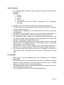
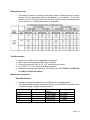
The Henderson Fire Department utilizes a wide variety of apparatus. The HFD takes pride in having a
modern fleet of firefighting, specialized, and support apparatus. Currently the department is ready to
respond with the following apparatus:
Station 81
Engine 81
Rescue 81
Station 82
Engine 82
Truck 82
Station 83
Engine 83
Rescue 83
Station 94
Engine 94
Rescue 94
Station 95
Engine 95
Rescue 95
Station 86
Engine 86
AR 86
Station 97
Engine 97
Rescue 97
Station 98
Engine 98
Truck 98
Station 99
Engine 99
Rescue 99
Rescue 82
Heavy Rescue 82
Batt. 8 EMS 8
Fire Boat 86
Rescue 98
Batt. 9
Apparatus | 1
01
Apparatus
-01.
Firefighting Apparatus
.01
Engines
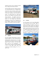
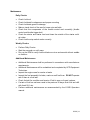
The engine is the most essential piece of
firefighting apparatus. The engines are
comprised of a “triple combination” including a
water tank, high capacity water pump, and
hose. The HFD engines have pumps capable of
flowing 1250 to 2000 gpm based on the type of
apparatus. Currently all front line HFD engines
have a 500 gallon water tank, and complements
of hose including 1 ¾”, 2 ½”, 3”, and 5” hose.
Three Second generation 2005 Pierce Quantum
engines (E83 #2048, E94 #2047, and E95 #2046)
Three First Generation Pierce Quantum engines
(E81 #2024 Reserve E #2022 Reserve E #2025)
HFD currently uses the following frontline
engines:
Two 2012 Rosenbauer engines (E97 #2083 and
E98 #2084).
Two Third Generation Pierce Quantum engines
(E82 #2063 and E99 #2070).
Additional
information
on
apparatus
specifications and equipment inventories can
be found on Citynet under Resource/Reference
and Vehicle Inventories.
.02
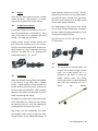
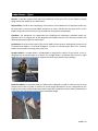
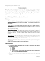
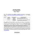
Aerial Ladder Trucks
HFD operates two 2005 Pierce Quantum aerial
ladder trucks (T82 #2044 and T98 #2045) out of
Stations 82 and 98. T82 and T98 provide the
department with a quick, efficient means of
operating above ground by the use of a
hydraulically operated aerial ladder. A “Truck”
(as it is commonly called) carries a compliment
of ground ladders, specialized tools and
Apparatus | 2
equipment used for rescue, ventilation, forcible
entry, salvage, and overhaul operations.
HFD aerial ladders are 100’ in length, triple axle,
rear mounted ladder trucks. An added feature
of the truck is that it includes a platform (also
known as the “bucket”) to transport members
of the truck company to the roof safely and
quickly. The bucket allows for a stable work
space for roof ventilation, and master stream
water operations. The ladders consist of 3
sections and are constructed of metal with
beams of a truss bridge type construction.
Additionally, the trucks carry a complement of
ground ladders including 35’& 28’ extension
ladders, 16’ roof ladders, and 10’ attic ladders.
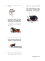
.03
.04
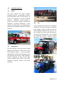
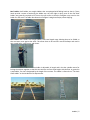
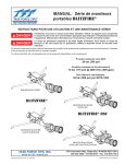
Fire Boat
The HFD operates one fire boat (FB86 #2056)
out of Station 86 at Lake Las Vegas. FB86 is a
Harbor Guard Boats Fire Hawk 26’. Overall it is
27’8” long, 7’6” wide, and has a dry weight of
6400 lbs. The boat can hold 8 to 12 passengers.
FB86 is a diesel powered jet boat and also has
an additional diesel engine powering its fire
pump. It is equipped with a deck gun as well as
up to three 2½” discharges for fire suppression
operations utilizing a 500 gpm pump.
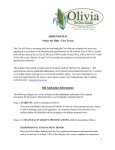
Skyboom
The Pierce Skyboom (E86 #2034) and Reserve
Skyboom (#2035) is a triple combination/aerial
ladder/elevated waterway with a 61’ ladder.
The Skyboom may operate as either an Engine
(E86) or used as a Reserve Truck when either
T82 or T98 are in for maintenance. The
Skyboom pump is capable of flowing 2000 gpm.
It has a 500 gallon water tank, and
complements of hose including 1 ¾”, 2 ½”, 3”,
and 5” hose.
Apparatus | 3
-02.
Specialized Apparatus
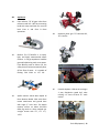
.01
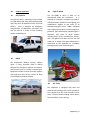
Rescue
The HFD currently has eight frontline
Freightliner Rescues. This apparatus is used for
the transportation of the sick and injured. All
rescues are equipped to perform paramedic
functions.
Equipment carried includes: a
gurney, back boards, oxygen administration
equipment, specialized medications, cardiac
monitor, first aid supplies, and communication
equipment that facilitate advanced life support
functions.
.02
.03
TRV
The HFD operates three Polaris Trail Response
Vehicles for use in off road rescues, and special
event staffing. Based on need, the TRVs are
housed between Stations 82, 86, and 99. The
TRV is capable of off road rescue and transport
of victims back to paved roads. The Six Wheel
TRV equipment includes a gurney, medical
equipment, stokes basket, and back boards.
Heavy Rescue
The HFD operates one Heavy Rescue (HR82
#2062) out of Station 82. HR82 is built on the
Pierce Quantum chassis. It carries personnel
and equipment to fulfill the requirements of the
HFD Technical Rescue Team. HR82 equipment
includes equipment for high and low angle
rescues, confined space, trench, swift water,
hazardous materials monitors, and heavy
extrication.
Apparatus | 4
-03.
Support Apparatus
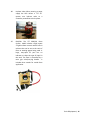
.03
.01
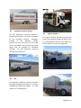
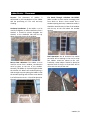
Chief Vehicles
The AR (AR86 # 2071) is built on an
International 4400 4x2 cab/chassis.
It is
available for emergency response to provide or
refill SCBA bottles, additional scene lighting, and
rehabilitation supplies at the scene of an
extended emergency event. AR86 is equipped
with a high pressure Bauer K-22.42 compressor,
generator, spare SCBA bottles, portable lights, a
bathroom, and cache of rehab supplies
including chairs, EZ-UPs, portable fans, heaters,
and a 120 gallon fresh water tank for sink and
rehab use. A supply of 24 spare SCBA bottles is
maintained on this apparatus for immediate
exchange at the scene of an emergency.
Currently the HFD is operating a fleet of both
Ford (B9 #2051) and Chevy (B8 # 2054) pickups
and Chevy SUVs for Battalion Chiefs, and Chief
Officers. Each is designed for emergency
transportation of department personnel and
may be used for a variety of roles including
mobile command posts.
.02
Light Air Rehab
EMS 8
The department Medical Services Officers
utilize a Chevy Suburban (EMS 8 #2053)
designed for emergency response to incidents,
and can also serve as a mobile command post.
Equipment includes a cache of medical supplies
and equipment that can be utilized on large
scale emergency medical incidents.
.04
TRT Trailer
This apparatus is equipped with tools and
materials used during trench rescue operations.
The equipment on the trailer includes circular
saws, a cache of wood including various precut
2x4s and OSB for trench shoring.
Apparatus | 5
.05
Equipment Technician Vehicle
The HFD Equipment Technician operates a
modified Chevy pickup. This vehicle is designed
for non emergency response.
Equipment
included
on
this
apparatus
includes
replacement parts and pieces for the SCBA,
power tools, ladders, and a cache of spare SCBA
bottles that are available for immediate
exchange. The HFD Equipment Technician
operates out of Station 95.
.06
.07
Logistics Vehicles
The Logistics division maintains and operates
various Chevy pickups (#1706 and 2064) as well
as an International 14ft Box truck (#2055) for
station deliveries and special assignments.
Bus
This apparatus is utilized to transport personnel
during non-emergency operations. It is a Chevy
cab/Eldorado national bus (#2067). The total
capacity is 15 including driver.
Apparatus | 6
Chapter
2
Tools & Equipment
Specialized tools and equipment are essential to successful firefighting and rescue operations. This
section includes a sample of the common tools and equipment utilized by the Henderson Fire
Department.
This chapter has been written under the premise and intent that will facilitate the addition or deletion of
equipment as the need arises. The tools and equipment found in this chapter are limited to the typical
equipment complement found on Engine Company inventories.
Specific Engine inventories can be found on CityNetDepartmentFireDocument CenterVehicle
Inventories
Tools & Equipment | 1
02
Tools and Equipment
-01.
Hand Tools/General Equipment
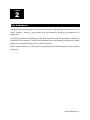
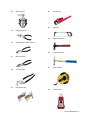
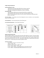
.01
Lanterns: Streamlight Survivor LED is a
light weight, right-angle flashlight
to clip onto turnout gear for easy,
hands-free use.
Super-bright LED,
narrow beam penetrates smoke, fog,
and mist for improved visibility.
Maximum lumens will produce a 4 hour
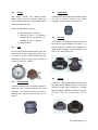
.04
Temp Gun: The CEN-TECH temperature
gun is an infrared laser thermometer
that can be used to check temperature
changes during HazMat incidents.
.05
HazMat pouch: contains the Centers for
Disease Control and Prevention NIOSH
guide to Chemical Hazards, The
Emergency Response Guidebook: A
Guidebook for First Responders during
the Initial Phase of a Dangerous
Goods/Hazardous
Materials
Transportation Incident (ERG), and
HazMat IQ flip cards.
.06
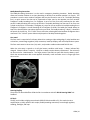
Thermal Imaging Camera: ISG Infrasys
Elite XR thermal imaging camera (TIC)
provides
thermal
imaging
at
temperatures in excess of 2,000°F. The
more you see, the safer you will be.
runtime.
.02
.03
Binoculars: Parks Optical 10x42
Carbon Monoxide monitor: Industrial
Scientific T40 Rattler is a low cost,
maintenance free single gas monitor
designed to protect personnel from
dangerous carbon monoxide gas
exposure.
Tools & Equipment | 2
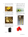
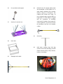
.07
Bee Veils: can be worn during bee
swarm incidents to protect the wearer
from bee stings to the head, neck, and
face.
.08
Decontamination Kit: Is used for rapid
gross decontamination in Hazmat
rescue situations. The kit contains two
Tyvek suits, soap, a roll of duct tape,
scrub brush, and a garden hose (Rescue
only).
.09
Drop Bag: Drop bags can be found
carried with each SCBA. Each bag
contains 50’ of rope that can be used
for multiple tasks including but not
limited to tool hoist, search, and rescue
.10
Portable Radio: The frontline radio
currently in use by the HFD is the
Motorola XTS 5000R. HFD main
communications channel is Zone 7
BATT9, and Zone 7 TAC 3 for all
structure fire responses and multi
companyincidents.
.11
Shovels: Fire suppression apparatus
carry at minimum a Round Tip, Square
Tip, and Scoop Shovel.
.12
Utility Rope Bag
operations.
Tools & Equipment | 3
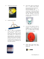
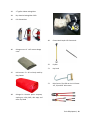
.13
5 gallon bucket of absorbent
.14
Push Broom with handle
.15
.16
Class B foam: Angus Fire Alcoseal ARFFFP is a superior quality AlcoholResistant Film-Forming Fluoroprotein
(AR-FFFP) firefighting foam
concentrate. HFD utilizes the 5 gal. 3%
concentration. A protein base material
provides a tough cohesive foam blanket
with high resistance to heat that
produces a vapor-sealing aqueous film
on hydrocarbons.
.17
Easy Susan: Was designed to allow two
firefighters to safely, effectively, and
efficiently load 5 in. pre-rolled supply
hose. An added benefit is the Easy
Susan can load any size hose.
.18
Rubber mallet: Nupla rubber mallet.
Rubber head weighs 2 lbs., overall
length of 16”.
Class A foam: ICL Performance
Products Phos-Check WD881 Class A
foam concentrate. Comes in 5 gal.
buckets. Class A foam makes water far
more effective for a variety of fire
fighting applications. High quality foam
reduces surface tension and increases
penetration into the fuel. Class A foam
is ideal for direct fire suppression, mop
up/overhaul, structure protection, and
many other operations.
Tools & Equipment | 4
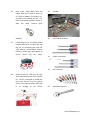
.19
Fox tail broom
.20
Foam Bucket Wrench: The Zephyr
Industries 70mm aluminum foam
bucket wrench allows for quick and
easy opening of foam bucket caps.
.21
.22
.23
Hose Spanners: HFD uses Zephyr
Industries Model 17 and Model 27
combination spanners, Akron Brass
Style 10 2½” spanners, Akron Akrolite
Folding Pocket spanners Style #14.
.24
Hurricane Monitor Remote Control: The
TFT Hurricane RC includes an electric
remote control capable of operating the
TFT
Hurricane
RC
deck
gun.
.25
Air hose
Hydrant wrench: The HFD uses a Red
Head Brass Adjustable Hydrant Wrench
with Single Spanner Head Style 107. It
will accommodate pentagon heads to
1¾” and square heads to 1¼”. The
single hook spanner head is designed to
fit ¾” to 6” rocker or pin lug fittings.
Hydrant key: Knox Keywrench provides
access to fire hydrants secured with
Knox
anti-theft
hydrant
caps.
Tools & Equipment | 5
.26
.27
.28
Hose straps: Akron Brass Hose and
Ladder Strap can be used to secure up
to 3”hose on ladders, fire escapes, etc.,
and aids in the handling of hose. It is
made of anodized aluminum with a 1”
wide, flat, water resistant nylon
.29
Tool Box
webbing.
.30
Flat Head Screwdrivers
.31
Philips Screwdrivers
.32
SAE nut drivers
.33
Adjustable wrenches
Lockout/Tag-out Kit: The Brady 65289
Lockout Safety Kit is a 12 piece lock out
tag out kit containing gate and ball
valve lockouts, lockout hasps, breaker
lockouts, lockout tags, and padlocks to
ensure lockout tag out safety.
Vehicle Access kit: HFD uses the High
Tech Tools Vehicle Access Tools Lockout
Kit. This kit is designed to include the
basic tools that are critical to gaining
access in any vehicle lockout with little
to no damage to the vehicle
Tools & Equipment | 6
.34
.35
.36
.37
Battery puller
.40
Pipe wrench
.41
Hacksaw
.42
Ballpeen hammer
.43
Framing hammer
.44
Tape measure
.45
Circuit tester
Long nose pliers
Diagonal pliers (side cutters)
Slip joint pliers
.38
Arc joint pliers
.39
Hex wrench set
Tools & Equipment | 7
.46
Kline cable cutter
.51
Spring loaded window center punch
.47
Air chuck with gauge
.52
Step chocks
.53
Door Chocks
.54
NY Hook: HFD carries Fire Hooks
Unlimited NY Hooks in 6’, 8’, and 10’
lengths. The NY hook has an allpurpose head and steel shaft that is an
essential tool on any interior fire attack.
.55
Pike Pole
.48
Air nozzle
.49
T-handle
PRV
adjustment
.50
Plug N Seal patching paste
tool
Tools & Equipment | 8
.56
Fire sprinkler head stoppers
.57
Security Torx wrench set
.58
.59
.60
Rubbish hook: The Nupla rubbish hook
was developed to find hidden fire in
deep seated smoldering fires normally
found in dumps or in dumpsters. The
rubbish hook utilizes two, large, six
inch, pointed prongs to grasp debris in
huge chunks. It is also used as a rugged
tool for ventilation of buildings
constructed of modern sheet materials,
such as plywood. It is the tool of choice
for sounding a roof due to its broader
surface.
.61
Street Key
.62
Swift water response bag: Each bag
contains two of the following: personal
flotation devices (PFD), knifes, whistles,
helmets, throw bags.
Hose roller
Squeegee with handle
Tools & Equipment | 9
.63
2 ½ gallon. Water extinguisher
.64
Dry chemical extinguisher 20 lb.
.65
CO 2 Extinguisher
.66
.67
.68
.69
Closet Hook: Nupla 4 ft Closet Hook
.70
Pry Bar
.71
Hay hook
.72
Bolt Cutters: The HFD carries H.K. Porter
18”, 24, and 36” bolt cutters.
Salvage cover: 12’ x 18’ canvas salvage
cover.
Hall runners: 3’ x 18’ red vinyl made by
King Canvas
Salvage kit: Contains precut visqueen,
staple gun, utility knife, duct tape, and
extra mop head
Tools & Equipment | 10
.73
Pick head axe: Nupla 6 lb. pick head
axe.
.74
.75
.78
RIT Tarp
Flat head axe: Nupla 6 lb. flat head axe.
The flat head axe along with the
Halligan make up the “Irons”.
.79
RIT Binder
.80
MDT Computer: Panasonic Toughbook
Halligan tool: The Paratech SPF
Hooligan is a single piece forged (SPF)
tool that is one of the world’s most
popular forcible entry tools. It is
designed to pound, puncture, twist, and
cut all types of barriers encountered by
fire personnel. It is 30 in. long and
weighs
9.7
lbs.
.81
Gas Detector: RKI Instruments Multi Gas
Detector GX-2012 can monitor the
standard confined space gases.
.82
Canberra UltraRadiac Plus Personal
Radiation Monitor is an easy to use
radiation monitor that measures and
displays radiation dose rate and total
dose.
.76
Axe belt
.77
RIT Bag
Tools & Equipment | 11
-02.
Power Tools
.01
AMKUS Power Unit: AMKUS GH2S-XL
Power Unit uses a Honda 4 cycle engine
to power a high pressure two-stage
pumping system to provide non-toxic
mineral based hydraulic fluid to the
tools.
.02
.03
60,000 lb. maximum cutting force.
.04
AMKUS Rams: Both the AMKUS AMK40R and AMK-60R provide a maximum
push force of 30,650 lbs. and a
maximum pull force of 14,400 lbs. The
40R over open length is 40.0 in. and the
60R open length is 60.3 in.
.05
Holmatro Power Unit: Holmatro PPU 15
Personal Power Unit uses a Honda 4
stroke engine to power a high pressure
pumping system to provide up to
10,500 psi maximum operating
pressure.
AMKUS Spreader: The AMKUS AMK30CX Spreader is capable of spreading
up to 32.0 in. at a force of 16,950 lbs to
gain access to victims requiring
extrication.
AMKUS Cutter: The AMKUS AMK-25
Cutter is an extremely compact,
powerful and versatile tool capable of a
Tools & Equipment | 12
.06
Holmatro Spreader: The Holmatro 4242
Spreader is capable of spreading up to
27.25 in. at a force of 12,925 lbs, and
the 4260 provides 33,000 lbs. maximum
spreading force at up to 32.75 in. to
gain access to victims requiring
extrication
.07
Holmatro Cutter: The Holmatro 4050
NCT is capable of a 208,000 lb.
maximum cutting force.
.08
Holmatro Ram bars: HFD carries the
Holmatro 4332 and 4350 ram bars. The
4332 has a maximum spread force of
36,460 lbs and a maximum extended
length of 64¼”. The 4350 has a
maximum extended length of 4915/ 16 ”
and a maximum 1st section spread force
of 49,145 lbs. and 2nd section spread
force of 18,210 lbs.
.09
Honda Generator
.10
50’ extension cord and twist locks
.11
Sawzall: DeWalt DW309 reciprocating
saw paired with an industrial grade, bimetal demolition reciprocating saw
blade can be used as another option to
gain access to a victim during
extrication
operations.
Tools & Equipment | 13
.12
Detachable Fire Research Corp. 750
watt light
.13
Circular Saw: Partner K1250 is the most
common power cutting tool used for
forcible entry. It is equipped with a
diamond tipped blade that can be used
to cut through locks, hardware, steel
doors, gates, and masonry among other
applications.
.14
Chain Saw: STHIL MS460 is used
primarily for ventilation purposes and is
equipped with a carbide tipped chain.
.15
Gas blower: The Unifire DST3P4 series
positive pressure ventilation (PPV) fan
features large flat proof pneumatic style
wheels and tires, 35" extendable
handle, high performance Honda
motor, stainless steel frame, is tiltable
from -10° to +20°, and provides stand
alone operation. It has an 18” four
blade fan and can put out 22,000 CFM.
Tools & Equipment | 14
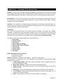
-03.
Appliances
.01
Foam eductor: TFT 95 gpm inline foam
eductor model UE – 095 has a metering
head with easy-read knob for use with
both Class A and Class B foam
operations.
.02
.03
.04
Stationary Deck gun: TFT Hurricane RC,
TFT Crossfire
.05
Portable Hydrant: HFD carries an Angus
3 way distribution gated ball valve
utilizing a 5” Storz to three 2½” male
outlets.
Blitzfire: The TFT Blitzfire is a simple,
light, and highly maneuverable attack
monitor. It can go anywhere a handline
goes while delivering much more water.
If the Blitzfire starts to slide or lift, the
safety shut off valve automatically shuts
off the flow of water. It is capable of
flowing 500 GPM at 175 PSI.
Apollo monitor: Akron Brass Apollo Hi
Riser Monitor Model 3431 with direct
mount attachment and ground base
with single 5” storz inlet. The Apollo
monitor utilizes an Akron 250-1250
GPM fog nozzle or Akron stacked tips
straight stream with 2½”, 1¾” 1½”,
1.375
Tools & Equipment | 15
.06
Hydrant Valve: When securing a water
supply the HFD utilizes a TFT 2½”
quarter turn hydrant valve as a
secondary connection to the hydrant.
.07
PRO/Pak: The TFT PRO/Pak Foam
System UM12 includes a high impact
2.5 gallon foam reservoir with a built-in
eductor that can be set to the ratio of
foam or wetting agents being used. A
large, easy-open fill port has an
indicator to show the type of liquid in
the tank. The flow is controlled by a
twist grip valve/carrying handle. It
includes three nozzles for varied foam
application.
Tools & Equipment | 16
-04.
Fittings
HFD fittings include: caps, double female,
double male, increasers, reducers, plugs, and
wyes manufactured by Red Head Brass, Akron
Brass, and Task Force Tips.
.03
Double Male
A double male fitting has male threads on each
end and is used to connect two female
couplings. Those currently in use are: 2½”
Fittings are identified in order by:
1. Size: female first – male last
2. Direction of flow – To indicate a
direction of flow, use the word “to”,
example: 2½” to 1½” reducer.
3. Name of fitting
.01
Caps
All caps have female threads and fit over the
male threads of the opening they cover. They
are used to protect male threads and cap
appliances or other fittings. Caps currently in
use are: 5” Storz, 2½”, and 1½”
.04
An increaser is a fitting with female threads on
one end and male threads on the other. It is
used to connect a smaller male coupling to a
larger female coupling. Those currently in use
are: 2½”x5” Storz and 2½”x4”
.05
.02
Double Female
A double female fitting has female threads on
each end and is used to connect two male
couplings. The threads may be the same or
different sizes. Those currently in use are: 2½”
and 1½”
Increaser
Reducer
A reducer is a fitting with female threads on one
end and male threads on the other. It is used to
connect a larger male coupling to a smaller
female coupling. Reducers currently in use are:
2½” to 1½”, 2½” to 1”, 5” Storz to 2½”, 1½” to
1”
Tools & Equipment | 17
.06
Plugs
flowing to the high rise hose.
All plugs have male threads and fit into the
female threads of the opening that they plug.
They are used to protect female threads and
plug appliances or fittings. Currently the HFD
only uses 2½” plugs.
.07
Wye
A wye is any fitting with one connection that
has female threads and two connections that
have male threads. They are used to divide one
hose line into two lines. It may or may not be
gated. The male threads may be smaller than,
or the same size as the female. Wyes in use
include the 2½” gated wye.
.08
2½” Line Gauge
The Red Head Brass Style 155 Threaded
Encased Line Gauge is found in the High Rise
Appliance bag and used during standpipe
operations to monitor and control the PSI
Tools & Equipment | 18
-05.
Nozzles
There are two basic types of nozzles, straight
stream and spray. Their purpose is to create
and control the type of fire stream desired.
.01
Straight Stream Nozzles
A complete straight stream nozzle consists of a
shut-off combined with a removable tip. Both
ends of the shut-off are equipped with hose
threads – one male and one female.
Straight stream nozzles increase velocity and
give shape and continuity to the fire stream.
They are particularly preferred for: penetration,
deep seated fires, quick knockdown, and long
distances. The HFD uses a 2½” playpipe with
stacked tips sized 1½”, 1¼”, and 1”.
.02
Fog Nozzles
Water has a greater cooling effect when applied
in the form of a fog rather than a straight
stream. A given quantity of water divided into
smaller particles presents greater surface area
for more rapid heat absorption. When properly
applied, a fog stream uses practically all of the
water in quenching and cooling.
water applied in the form of a spray. They are
therefore well suited for use in situations where
the supply of water is limited. Also, fog nozzles
have less nozzle reaction than straight stream
nozzles under similar conditions.
The disadvantage of fog streams may include
loss of water through evaporation, dissipation
by wind, inability to span great distances, loss of
striking power and penetration.
The HFD uses the TFT 2½” Fog nozzle, and 1½”
TFT fog nozzles.
.03
Piercing Nozzle
.01
The Akron Brass Piercing Nozzle and
Shut off can be used through concrete
block, cars, mobile homes, etc. It is
designed to get water or foam into
hidden trouble spots. The driving
button and point are made of hardened
tool steel with impinging jets for a
dense
fog
pattern.
Discharge from a fog nozzle may provide a flow
of air toward the fire. While this may increase
the intensity of the fire, it has the advantage of
providing a flow of cool air at the nozzle.
Fog nozzles can use considerably less water
than straight stream nozzles to affect the same
results because of the added effectiveness of
Tools & Equipment | 19
.04
Foam Adaptor
Currently the HFD utilizes the TFT MX-FOAMJET
and the FJ-H Air-aspirating foam-making
attachment. They provide a flow range of 70 200 gpm.
Tools & Equipment | 20
Chapter
3
Self Contained Breathing Apparatus (SCBA)
The Self-Contained Breathing Apparatus is one of the most vital fire ground tools. SCBA use shall be in
accordance with HFD Equipment Guideline EG-02 SCBA and IPS-02 Donning SCBA Task Standard. The
SCBA allows you to carry your own air supply that is entirely independent of the outside atmosphere.
Compressed air is contained in the SCBA cylinder. High pressure air (up to 4500 PSI) is reduced by the
first and second stage regulator to a breathable pressure. Exhaled air is exhausted to the outside via the
mask.
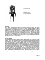
The air cylinder is attached to the back pack harness which contains both regulators. The HFD uses the
Dräger PSS 7000 SCBA. The Dräger SCBA is designed to provide the wearer with respiratory protection
while working in hazardous atmospheres. This unit may be used for entry into and escape from
hazardous or oxygen deficient atmospheres.
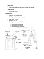
The SCBA Consists of 7 Major Component Groups:
1. Back pack and harness assembly
2. Air Cylinder
3. First stage regulator / whistle alarm system
4. Second stage regulator (LDV)
5. Sentinel 7000 PASS device and PASS alarm enunciators
6. Buddy breathing connection
7. Face mask with heads up display and voice amplification systems
Back Pack and Harness:
A key feature of the Dräger PSS 7000 is a newly designed harness suspension system that provides the
ultimate in comfort and wear. The system features advanced compression-molded comfort padding.
The high grip anti-slide outer surface of the harness is made from a vulcanized chloroprene rubber for
the necessary stability to keep the harness securely in position. A unique feature of the Dräger SCBA is a
backplate that provides unrestricted movement that can fit the torso lengths of different firefighters.
The carbon fiber composite backplate features a unique 3-position height adjustment. This feature
allows the wearer to adjust the height of the backplate within seconds. The backplate automatically
lengthens and pivots to accommodate the user’s movements, and the unique self-adjusting, pivoting
waist belt allows the backplate to do this. In addition to an increased range of movement, the weight of
the SCBA rides on the hips to reduce back strain. This also increases stability and balance by providing a
lower center of gravity. The carry and drag handles have carabineer and webbing connection points.
The side handles have a pull force of up to 600 lbs., and the yoke has a pull force of up to 750 lbs.
SCBA | 1
Reflective shroud for increased safety
Sentinel™ 7000 Digital Gauge
Swivel & Pivot Waist Belt
“Slide and Lock” Harness Connections
Integrated Hose Channels
Buddy Breathing Multilink
Pull Forward Waist Adjustment
Air Cylinder:
The air cylinder utilizes a composite carbon fiber construction. A pressure indicator, built into the
cylinder valve, indicates the pressure of air currently in the cylinder. The gauge is graduated in 1000 PSI
increments ranging from 0 to 4500 PSI. A cylinder that is full (bottle range 4000-4500 PSI.) is identified
on the gauge in green. There are two sizes of air cylinders; 45-minute and 60-minute. When full, the
cylinders contain 66 and 88 cubic feet of air respectively and will provide air supply time of 45 minutes
or 60 minutes at a user rate of 40 liters per minute during moderate activity. Actual air supply time will
vary, depending on demands of the user, and will frequently be less. The air cylinder is hydrostatically
tested every five years. An added feature of the air cylinder is its ability to utilize the quick connect lock
and load system for quick air cylinder swap out.
First Stage Regulator
The first stage regulator combines a pressure regulator and EOST whistle alarm system in one compact
assembly. The first stage regulator reduces air cylinder high pressure to approximately 100-110 PSI
(medium pressure). This medium pressure is found in the hose from the first stage regulator to the
second stage regulator, and in the hose to the buddy breather. The audio alarm activates a whistle
when the remaining usable air supply has dropped to approximately 20% - 25% of cylinder capacity, or a
cylinder pressure of approximately 1215 to 1035 PSI. In addition, there is an integral pressure-limiting
device built into the first stage body, which maintains a safe outlet pressure in case of failure within the
primary regulator (due to wear, corrosion, damage, etc.). If failure of the first stage regulator occurs,
the regulator will fail in the “open” position and the whistle will sound to alert the user that a failure
occurred. The user is able to continue breathing at normal respiratory rates. If this occurs, notify your
partner and immediately exit the hazardous environment. Other features found connected to the first
stage regulator include the cylinder quick-connect system, and Protected UAC fitting.
SCBA | 2
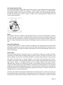
Second Stage Regulator (LDV)
The second stage regulator (Figure #15) reduces the air pressure received from the first stage regulator
to just above atmospheric pressure. The regulator is carried in a holster mounted on the right waist belt.
The regulator mounts to the face mask in a “quick-connect” fashion. Push the lung demand valve into
the face mask opening until a “click” is heard. To begin “on-air” breathing, inhale or depress the LDV
manual override button (2).
Bypass
The red bypass valve (3) is capable of supplying 80-120 liters of air per minute, depending on how far
the valve is turned. This valve has a detent to prevent accidental activation of the bypass. Depress and
turn the valve counterclockwise to activate. The bypass valve can be used when needed to provide a
flow of air above atmospheric pressure and will consequently reduce the duration of air supply to the
user.
Release/Shut Off Buttons
The black release buttons are used to remove the regulator from the holster and face mask. When
removing the regulator from the face mask, first press the black shut-off button (1) on the LDV to turn
off positive pressure. Then depress the black release button on the face mask and twist off the LDV to
remove the regulator.
Sentinel 7000
The Sentinel 7000 electronic monitoring system is a multi-function system that provides continuous
monitoring of the SCBA status including remaining cylinder pressure, movement of the wearer, main
battery condition, end-of-service time (EOST) and PASS. It provides visual indications of system status
and audible and visual alarms in warning conditions. User control and monitoring of the system is
through a user interface that incorporates switches, LEDs, a liquid crystal display (LCD) display screen
and an alarm sounder. A backlight illuminates the user interface display screen when required.
Additional alarm sounders are mounted on the back of the backpack to the left and right of the air
cylinder, with warning LEDs on the top and bottom, and operate only during PASS alarms. The operating
settings are preset and non-adjustable by the user. The motion sensor in the PASS is an accelerometer.
The accelerometer is more sensitive swinging left to right than front to back. It must be in motion, and
changing direction to reset the PASS alarm.
Activation: The PASS function of Sentinel 7000 electronic monitoring system is an alarm system that can
be activated manually or automatically. The automatic alarm uses a motion sensor to detect movement
and activate a pre-alarm and main alarm at timed intervals when no movement is sensed. The manual
SCBA | 3
alarm is activated by a yellow press button on the user interface. When activated the following selfcheck sequence will commence:
First stage – The Sentinel 7000 will emit a single tone from the user interface and the additional alarm
sounders, and the display backlight will illuminate.
Second stage – The display will show a tick symbol (Fig 9); the blue, red and green LEDs (Fig 10) will
illuminate.
Third stage – The display will show the cylinder type (Fig 11) (2216 PSI or 4500 PSI).
Fourth stage – The display will show the normal operating screen (Fig 12); the blue, red and green
LEDs (Fig 10) will illuminate; the blue and red LEDs (1, Fig 13) will illuminate.
End of sequence – Two ‘trill’ alarms will sound; the display will show the normal operating screen (Fig
12); the green LED (Fig 10) will flash at approximately one second intervals to confirm that the
Sentinel 7000 has passed the self check and is in the active mode.
Up to approximately 45 seconds after the start of the self check, all six HUD LEDs (Fig 14) will flash twice
to indicate that the Sentinel is communicating with the HUD. The HUD LEDs (red/amber/green/green)
will flash (on for 15 seconds/off for 45 seconds). Check that the blue LEDs on the backplate are
functioning.
React to the following alarm and warning signals as necessary:
PASS Pre-Alarm – Alarm starts after 20 seconds with no PASS movement. A repeating audible alarm
tone (3 medium tones, then 1 low tone in succession; Volume increases from 25 to 29 sec.) will be
emitted from the user interface sounder and the additional alarm sounders. Move the user interface
to cancel the alarm (do not attempt to use the buttons to switch off the pre-alarm).
PASS Full Alarm – Full alarm will activate after 30 seconds with no PASS movement. A high-level
sweeping alarm (continuous ascending low to high tones) will be emitted from the user interface
sounder and the additional alarm sounders; red and blue LEDs on the user interface and top and
bottom of the additional alarm sounders will flash intermittently; the user interface will show the
alarm icon. PASS full alarm emits 95 decibels at 10’ in all directions. Simultaneously press and hold
the RH and LH buttons of the user interface to cancel the alarm.
50% Air Alarm – PASS will emit 2 identical loud electric tone beeps at 2250 PSI.
EOST 25% Air Alarm – The EOST alarms will activate when the PSI drops below 1125 PSI. The user
interface will emit an audible alarm tone (continuous electronic cricket tones 2 seconds on and 2
seconds off), and red and blue LEDs will flash; the red LED on the HUD will flash; the mechanical
whistle on the first stage regulator will sound. The mechanical and electric alarms are independent
and one may start before the other. The mechanical whistle will operate independently of the
Sentinel electronics. Either of the EOST 25% alarms may start at up to 1180 PSI.
SCBA | 4
Dräger LED Light Explanation
Sentinel PASS device 5 LED’s
1 green Flashes continually when PASS device is sensing or any alarm.
2 red Flash continually when PASS device is in low air or full alarm.
2 blue Flash continually when PASS device is in low air or full alarm.
Back frame 4 LED’s
2 blue face down and flash every 20 seconds when PASS is in sensing mode.
2 blue face down and 2 red face up. Flash every 5 seconds during low air alarm.
When in Full Alarm Mode the same 2 blue and 2 red flash continually and rapidly when PASS
device is in full alarm.
Low main battery – A low battery icon will be displayed on the user interface or the Green/Yellow
battery LED will flash yellow.
Low HUD battery – The Green/Yellow battery LED will flash green.
Loss of HUD communication – The HUD blue LED will flash
Mask Heads Up Display (HUD)
When the SCBA is turned on, all 6 mask LEDs illuminate to full brightness on startup. The wireless signal
(blue), and low battery LED (green/yellow) are the last 2 LEDs. After initial start up, the 4 pressure LEDs
are on for 15 seconds and off for 45 seconds. The Cycle will repeat itself. Any ¼ pressure change causes
lights to refresh and restart the 15-45 cycle. Depressing the right button on PASS refreshes and restarts
the 15-45 cycle. An ambient light sensor adjusts brightness of LED’s.
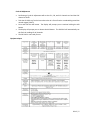
HUD Pressure Gauge
Uses 4 LED’s in succession. (15 seconds on 45 off)
2 green, 1 yellow, 1 red
Full 4500 - 3376 PSI 2 green, 1 yellow, 1 red
¾ 3375 - 2251 PSI 1 green, 1 yellow, 1 red
½ 2250 - 1126 PSI 1 yellow, 1 red flashing yellow for 20 seconds then 15-45.
¼ 1125 - 0000 PSI 1 FLASHING BRIGHT RED CONTINUOUS. No 15-45 cycle.
SCBA | 5
Buddy Breathing Connection
The Buddy Breathing Connection is to be used in emergency breathing situations. Buddy breathing
allows one member without air to share breathing air directly from another member’s air supply. This
procedure is used to assist another firefighter that may be low and or out of air. The buddy breathing
line is a quick connect line that can be connected to either port by the opposite port from another
firefighter’s buddy breathing line. If a firefighter is out of air they must stay connected to the other
person’s buddy breathing line until out of the IDLH. The buddy breathing line does not fill air from one
cylinder to the other. For example; if firefighter A is out of air he can connect his buddy breathing line to
firefighter B, firefighter A is now breathing off of firefighter B’s SCBA. The buddy line should always be
kept in the pouch and the caps always kept on the port ends. The buddy breathing “Y block” is located in
the pouch on the left hip. The “Y block” hose is 40 inches, allowing 80 inches between firefighters when
connected. The “Y block” system allows multiple packs to be daisy chained together.
Face mask
The face mask is comprised of a silicone rubber skirt creating a triple sealing edge, 5-point head harness
or head net, second stage regulator (LDV) connection, heads up display, and voice amplification system.
The face mask comes in three sizes S, M, and L, and provides a wide unobstructed field of view.
When the voice amp is turned on it will give battery condition with beeps. 3 beeps indicate fully
charged. 2 beeps indicate ½ capacity. 1 beep or no beeps requires battery replacement. The voice amp
on the mask uses 2 AAA batteries. Use finger pressure (no tools) to open and close the battery cover.
Check the communication dock screw opposite the battery cover and make sure it is finger tight from
time to time.
Donning/Doffing
The process to don and doff the SCBA shall be in accordance with HFD IPS-02 Donning SCBA Task
Standard.
RIT Pack
The RIT pack includes a high pressure bottle (4500 PSI 60 minute 88 cu ft.), face mask (no voice
amplification or HUD), rapid fill UAC coupler, buddy breathing connection, second stage regulator,
webbing, flashlight, and rope.
SCBA | 6
Air Cylinder Over Pressurization
Department personnel need to keep an eye on SCBA bottles for over pressurization.
How does a bottle become over pressurized?
A bottle filled to near 4500 PSI when the season is cooler, and cool inside the station, will heat up on
warmer days causing increased pressure. As it gets hotter and hotter, more bottles will creep over 4500
PSI. A couple of packs and one RIT pneumatic have been taken out of service because of this.
Leaving a full bottle exposed to direct sunlight on a hot day will easily increase pressure in the bottle to
over 5000 PSI. As the season continues to warm up some bottles may need to be purged a couple of
times if they are kept near 4500 PSI.
This may seem insignificant but it is not. A bottle with “extra air” over 4500+ PSI, and the valve open on
your SCBA may cause the pressure release valve on the SCBA first stage regulator to open and slowly
bleed off the air dropping the pressure down to about 3400 PSI before resetting. You will not hear it
unless you put your ear close to the first stage regulator. That’s how it works. The air cylinder is being
safe because it has too much pressure in it!
A bottle is full at 90% to 100 % capacity. This equals 4050 to 4500 PSI.
4501 PSI is over pressurized and shall not be used.
THIS IS SERIOUS!
Please do not use a bottle with over 4500 PSI on your SCBA. THERE IS NO ADVANTAGE. You may end up
with less air than usual and an Out Of Service SCBA. Please purge excess pressure from your SCBA bottle
while separated from the pack before use. Every time an SCBA pressure release valve vents pressure, its
threshold for release becomes slightly lower the next time. Eventually this can take the SCBA out of
service.
SCBA | 7
Chapter
4
HFD Hose Manual
The purpose/intent of the HFD Hose Manual is to standardize the methods, skills, and knowledge to be
employed by personnel of the Henderson Fire Department in relation to fire ground hose evolutions.
It shall be the responsibility of all members of the Henderson Fire Department who may be required to
execute hose operations as a part of their normal duties and function to remain familiar with and be
able to perform the practices outlined in this document.
This document shall consist of this cover page and all related subsections which deal with one or more
specific hose operations and or evolutions adopted by the Henderson Fire Department.
This document has been written under the premise and intent that will facilitate the addition or deletion
of material as the need arises.
The attempt will be to cover all practices which a firefighter may be called upon to perform during basic
hose evolutions as may be dictated, but not limited to, emergency incidents and training scenarios.
Most commonly, the primary responsibility of an engine company is to apply an extinguishing agent to
an existing fire. Although engine company members are often required to perform tasks other than
agent application, this Chapter is dedicated to the various evolutions used to provide water to a fire.
There are many factors which will determine the type of hose evolution to be applied to a given
situation. Whether or not fire is visible during response, the volume of fire, the location of the fire,
exposure problems and potential life hazard are but a few of the factors which will determine the size
and number of lines to be used. This information is taken into account by the first arriving officer. The
method of choice must be put into operation quickly, safely and effectively.
Hose | 1
Hose General
Hose used by the HFD is of the following sizes: 5”, 3”, 2½”, 1¾”, and 1”. Hand line hose lengths come in
50’ and 100’ sections, but may be shortened during repairs.
Hose Construction
The fire service uses the following national standards for fire hose and couplings:
NFPA 1961 – Standard on Fire Hose
NFPA 1962 – Standard for the Care, Use, and Service Testing of Fire Hose Including Couplings
and Nozzles
NFPA 1963 – Standard for Fire Hose Connections
Currently, the HFD uses two types of fire hose:
1. Synthetic double jacket, rubber lined N-Dura® hose (hand lines, 3”).
2. Nitrile, rubber lined (5”).
Hose Maintenance
The typical warm climate in Southern Nevada allows wet hose to dry quickly, however, it is important
that dirty, wet hose be properly cleaned. Hose shall we washed with clear, cold water, and mild soap
when heavily soiled. Soap must be thoroughly rinsed from hose prior to reloading on the apparatus.
Repairs
Hose shall be repaired by the HFD Logistics Division. Damaged hose forwarded to Logistics shall be
clean, dry, rolled, and Red Tagged.
Rolling Hose
Hose is rolled to simplify storing, carrying, and deployment during emergency and nonemergency
situations. Different hose rolls will permit more effective fire ground operations and efficient cleanup.
There are several methods for rolling hose:
• In-Service Roll (Donut)
• Out of Service Roll
• Double Donut Roll
• Large Diameter Hose Roll
• Drain & Carry
When rolling hose for use (In-Service Roll), it shall be rolled with the MALE coupling forming the core.
When rolling hose for storage (In-Service Roll) it shall be rolled with the MALE coupling forming the core.
When rolling hose for repair (Out of Service Roll), it shall be rolled with the FEMALE coupling forming the
core.
Task Benchmarks – In-Service Roll
1. Lay the hose out flat and straight on a clean surface.
2. Begin rolling the hose at the male coupling and tightly fold coupling onto top of the hose.
Continue to roll the hose towards the female coupling. Keep the edges of the hose aligned.
3. When reaching completion of the roll, do not roll the hose over the female coupling. Lay the
hose roll on its side and wrap female coupling into the roll.
4. Protruding hose roll edges can be made orderly by stepping on the roll while still flat on the
ground.
5. Prepare hose for deployment. Stand hose roll on end with female coupling on the ground.
Secure the roll with both hands along edges of roll.
Hose | 2
6. Ensure a safe work area before deployment.
7. Unroll hose using a “bowling” movement. Keep the roll aligned and hose straight. Protect
male coupling as it is unrolled.
COUPLING AND UNCOUPLING HOSE
The terms coupling and uncoupling hose defines the process of attaching and disconnecting male,
female, and storz couplings to any two sections of hose. The process of coupling and uncoupling hose
sections together requires screwing together threaded male and female hose couplings, or snapping
together two storz couplings to make a continuous water way. The need for speed and accuracy under
emergency conditions requires that specific techniques be used. In many cases, nozzles and fittings may
be attached and detached using the same techniques for coupling and uncoupling hose. The following
methods should be used when coupling and uncoupling hose:
• Foot-Tilt Method
• Two-Person Method
• Utilizing Spanners Method (Tight Coupling)
Hose Line Safety
To provide greater safety for personnel and equipment while using hose lines, the following procedures
shall be adhered to:
1. Nozzles shall be shut off after attachment to hose lines and at any other time the flow from
the nozzle ceases.
2. When practical, hose lines that are operated from ladders, roofs, or other heights shall not
be charged with water until after such lines have been secured in position.
3. Where possible, hose to upper floors shall be cleared from ladders and secured in order to
provide safe operation.
4. Personnel shall not direct or cause a stream of water from a line to be directed upon any
person or into any premises unnecessarily.
5. Care must be taken any time hose streams are used from ladders, as to not put undo forces
on the ladder.
Backing-Up the Nozzle
The purpose of backing up the nozzle is to relieve the strain caused by the reactionary force of the
stream. Positions of members holding the hose line should be staggered. Do not crowd the member at
the nozzle. Keep the hose line free of sharp bends, and maintain the hose in-line with the nozzle to
absorb back pressure.
The method of Backing-up the nozzle/hose depends largely on the number of members available, size of
the hose, pressure, location, and the length of time the hose is to be used.
Hose Combinations
To effectively carry out firefighting operations, it may be necessary to extend, reduce, increase, or wye
off hose lines. Various combinations of hose, nozzles, and fittings are used for this purpose. It is
recommended whenever possible that all hose, nozzles, and fittings are assembled before connecting to
the original working line. A detailed list of HFD nozzles, appliances, and fittings can be found in Ch. 2
Tools & Equipment sections -03 through -05.
Hose | 3
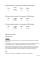
Hose Compliment
All Engines carry the following hose:
1. 200 ft. 1¾” pre-connect cross lays (2)
2. 300 ft. 1¾” pre-connect (1)
3. 100 ft. 1¾” pre-connect (1)
4. 300 ft. 2½” pre-connect (1)
5. 800 ft. 5” dead load
6. 300-400 ft. 2½” dead load
7. 100 ft. 1¾” Feed Bags (2)
8. 50 ft. 2½” High Rise Bundles (3)
9. 100 ft. 1” rolled PRO/pak hose (1)
10. 3” rolled Soft Suction (1)
11. 5” rolled Soft Suction (1)
Loading Hose
Hose is used in two basic ways, in a supply capacity it transports water from the source to the pump,
and in an attack capacity it transports water from the pump to the nozzle(s). Hose should be arranged
in the hose bed so that when the hose is laid, the end with the female coupling is towards the water
source and the end with the male coupling is towards the fire. All threaded appliances and fittings are
constructed following this philosophy.
Hose loading is standardized across the department. 1¾” cross lays on Pierce & Rosenbauer Apparatus
are pre-connected with two loops for ease of removal and deployment. 2½” is loaded at the rear of the
apparatus in both a pre-connected minuteman load for easy one, two, or three member deployments,
as well as a 2½” dead load (flat load). 5” supply line is also loaded flat.
When loading hose, a few basic guidelines should be followed:
• When possible, load clean, dry hose
• Assure ground is clear of dirt and debris before laying out hose to be loaded
• Check for the presence of gaskets in all swivels
• Connect hose so that the edges are in the same plane
• Hand-tighten all connections
• Load the hose so that couplings will pull off without flipping over. This may require a Dutchman
in the hose (see explanation below)
• Avoid packing hose too tightly
• Keep folds at edge of bed and neatly organized, do not place couplings too close to folds
Hydrants
Fire hydrants in the City of Henderson are of two types, Public and Private. Both types are dry barrel
hydrants, with a 5” and two 2½” threaded discharges. The standard is that Public COH hydrants are
painted yellow, and Private hydrants on privately owned land are painted red. Although this is usually
the case a situation may arise that hydrant color might not match with use.
Hose | 4
Two Phases of a Hose Evolution
Supply Phase: That phase of a hose evolution which allows the engine apparatus to secure a constant
source of supply from a hydrant.
Fire Fighting Phase: The removal of the selected line or lines from the apparatus and the advancement
of those lines to the objective.
Forward and Reverse Evolutions
Forward Evolution (Hydrant to fire): The type of hose evolution which begins with the laying of a line
from a hydrant or other source of supply. Supply Phase should be completed first.
Reverse Evolution (Fire to hydrant): The type of hose evolution which begins at the fire and proceeds to
the hydrant or other source of supply. Fire Fighting Phase should be completed first.
Definitions:
Coupling: Couplings are to be hand-tight, unless conditions warrant the use of a spanner.
Dressing the hose: Make it orderly. This enables finding the hose patterns. It also removes
some of the kinks from the hose.
Nozzles: When a nozzle is connected or grounded, it shall be shut off in all cases. When
grounded, the hose is straightened for at least 5' behind the nozzle.
Dutchman: A Dutchman is placed into the hose load to prevent a coupling from flipping over
when the hose is pulled from the bed. It consists of a small section of hose folded back on itself
next to a coupling. The Dutchman is placed on the side of the coupling opposite the direction
that the hose would normally be pulled from the bed. A Dutchman is not required in a hose bed
where the hose may be deployed in either direction (transverse pre-connect).
Hose Evolutions
The hose evolutions required to be performed by all Fire Rescue Operations Personnel include the
following Task Standards:
• TS-01
Fast Attack
• TS-02
2½” Hose Deploy – One Person
• TS-03
2½” Hose Deploy – Two Person
• TS-04
2½” Hose Deploy – Three Person
• TS-05
Foam Eductor
• TS-06
Foam PRO/pak
• TS-07
Fire Attack High Rise Standpipe Evolution
• TS-08
3” Hose to 1¾” Feedbag
• TS-09
Portable Monitor Attack
• TS-10
Deck Gun (Blitz Attack/Defensive Ops)
• TS-11
Elevated Master Stream
• TS-12
Relay Pump
• TS-13
Elevated Master Stream (Sky-Boom)
Hose | 5
Chapter
4
5
HFD Ground Ladder Manual
The purpose/intent of the HFD Ground Ladder Manual is to standardize the methods, skills, and
knowledge to be employed by personnel of the Henderson Fire Department in relation to ground ladder
practices.
It shall be the responsibility of all members of the Henderson Fire Department who may be required to
execute ground ladder operations as a part of their normal duties and function to remain familiar with,
and be able to perform the practices outlined in this document.
This document shall consist of this cover page and all related subsections which deal with one or more
specific ground ladder practices and/or evolutions adopted by the Henderson Fire Department.
This document has been written under the premise and intent that will facilitate the addition or deletion
of material as the need arises.
The attempt will be to cover all practices which a firefighter may be called upon to perform during
ground ladder evolutions as may be dictated, but not limited to, emergency incidents and training
scenarios.
Ladders |
Table of Contents
LADDER BASICS
Ladder Terms
Ladder Commands & Communication
Ladder Types
Ladder Placement
1-4
5
6-7
8-9
SECURING THE LADDER
Ladder Footing
Tying the Halyard
10
11
CLIMBING LADDERS
General Climbing Technique
Working on a Ladder (Locking-In)
12
13
LADDER EVOLUTIONS – One Person
One Person Low Shoulder – Carry & Raise
One Person Low Shoulder – Lowering
One Person High Shoulder – Carry & Raise
One Person High Shoulder – Lowering
14-17
18-19
20-22
23
LADDER EVOLUTIONS – Two Person
Two Person Low Shoulder – Carry & Flat Raise
Two Person Low Shoulder – Lowering Flat
Two Person Low Shoulder – Carry & Beam Raise
Two Person Low Shoulder – Lowering on a Beam
24-29
30-31
32-35
36-38
LADDER CARE AND MAINTENANCE
Aluminum Ladders General Care & Maintenance
39-40
Ladders |
Ladder Basics – Terms
Terms: It shall be the responsibility of all members of the Henderson Fire Department who may be
required to execute ground ladder operations as a part of their normal duty and function to remain
familiar with ladder terms and definitions.
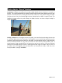
Ground Ladder: Term used to designate the
difference between ladders raised on the
ground and those raised from the apparatus
such as a Truck Co. or Ladder Co.
Straight Ladder: Used to identify a ladder of
one section (also known as a single ladder or
wall ladder).
Bed Section: Describes the lower section or
bottom section of an extension ladder (also
known as the main section).
Fly Section: The upper section or top section of
an
extension
ladder.
Tip: The extreme top of the ladder.
Extension Ladder: Term used to identify a
ladder with two or more sections.
Ladders | 1
Base: Bottom or ground end of ladder (also
known as butt or heel).
Shoes: Metal safety plates attached to the base
of a ground ladder to stabilize the ladder and
protect the beam ends (also known as heel
plates or butt spurs).
Beam: One of two principal sides of a ladder.
Rungs: Cross members between the beams on
which people climb.
Gusset Plates: Plates which are attached to
beams by rivets that are used to support rungs
(also known as Truss Blocks).
Pulley: Small grooved wheel through which the
halyard is drawn.
Halyard: Rope or cable used for hoisting fly
sections.
Main Beam: The principal beam of an extension
ladder.
Ladders | 2
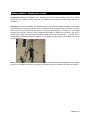
Dogs: Metal devices attached to the inside
beams on fly sections of extension ladders.
Dogs are used to hold the fly section in place
after it has been extended (also known as pawls
or locks).
Anchor: The part of the ladder which is used to
attach the halyard to the ladder.
Guides: Metal strips on an extension ladder
which guides the fly section and holds the fly to
the main section while being raised; sometimes
in the form of slots or channels.
Balance Point: Point of a ladder where weight is
distributed evenly. Balance point is marked with
blue reflective tape along beams of ladder.
Stops: Metal pieces which prevent the fly from
being extended out of the main section.
Ladders | 3
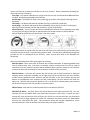
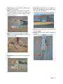
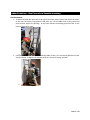
Fire Ladder Labels: One set/pair of Danger/Electrical/Angle labels are required for each ladder. The
labels should be placed at the bottom of the ladder, outside the rail of the base section, both sides,
between the 4th and 5th rung up from the bottom. Be sure the left label is placed on the left side, and
the right label is placed on the right side. If placed on the wrong sides of the ladder, they will not make
sense for ladder placement.
Heat Sensor Labels: These are visual warning labels furnished on all aluminum and fiberglass ladders
since January, 1984. These labels are heat sensitive materials that turn black if any heat is ever present
that is greater than approximately 300 degrees F. The 300 degree F temperature is used because once
aluminum fire ladder materials (6061-T6 alloy) reach this 300 degree F (even if only for a moment), the
ladder material may have lost at least 25% of its load capacity. This heat exposure effect is not reversible
in the ladder and can continue to accumulate over its entire life.
Ladders | 4
Ladder Basics – Commands & Communications
Purpose: To clearly define the ladder evolution language and communication that takes place while
performing ground ladder operations. By standardizing the ladder language it is the intent that this will
facilitate ladder operations and make for a safer, more consistent, and more efficient ladder evolution.
Responsibility: It shall be the responsibility of all members of the Henderson Fire Department who may
be called upon to execute ground ladder operations to remain familiar with the ladder evolution
language/ communication adopted.
Procedure: The Henderson Fire Department has identified the information contained within this
document to be an integral part of the adopted ground ladder practices. This document contains the
following information within its subsection(s).
Introduction
One of the most important factors in the smooth operation of ladders is the proper use of ladder
commands. All personnel working with ladders should be familiar with the exact communication that
takes place when executing a ladder evolution. Only one person will be tasked with issuing the ladder
commands. The person at the base of the ladder will be the designated the Ladder Commander.
The ladder commands used by the Henderson Fire Department are:
1. “Beam Ladder”
2. “Shoulder Ladder”
3. “Raise the Fly”
4. “Lower Ladder into Building”
5. “Remove Ladder from the Building”
6. “Lower the Fly”
7. “Reverse Ladder”
8. “Ground Ladder”
9. “Bed Ladder”
Ladder commands are given in two parts:
1. Preparatory command
2. Execution command
Example: “Preparatory- “Prepare to beam ladder…” “Execution- “Beam Ladder…”
The Henderson Fire Department also uses standardized communications while executing ladder
operations. These include:
1. “Ladder coming through”- safety order used to alert others on the fire ground that you are
operating nearby with a ladder.
2. “Beam raise or flat raise”- informs partner which raise will be executed.
3. “Fingers and toes”- safety order for partner to check that hands and feet are clear from
moving fly section.
4. “Dogs locked”- safety order telling ladder commander that the dogs have been secured.
5. “3, 2, 1 building – safety order used to notify base person how close the ladder tip is to
making contact with the building.”
6. “Clear”- safety order given to alert others that the ladder is coming down.
Ladders | 5
Ladder Basics – Types
Purpose: To provide members clear and concise definitions of the types of fire service ladders currently
being used by the Henderson Fire Department.
Responsibility: It shall be the responsibility of all members of the Henderson Fire Department who may
be called upon to execute ground ladder operations to remain familiar with the types of fire service
ladders being utilized and carried on City of Henderson Fire Department apparatus.
Procedure: The Henderson Fire Department has identified the information contained within this
document to be an integral part of the adopted ground ladder practices. This document contains the
following information within its subsection(s).
Introduction: All of the various types of fire service ladders have a purpose. Although the primary use of
fire department ladders is to provide firefighters a means of accessing upper floors of a structure,
ladders are a versatile tool having many other uses.
Straight Ladders: A straight ladder is nonadjustable in length and it consists of one section. Its size is
designated by the overall length of its beams. The straight ladder is sometimes called a wall or single
ladder and it is used for quick access to windows and roofs of one and two story buildings.
Extension Ladders: An extension ladder is a ladder that is adjustable in length. It consists of two or more
sections which travel in guides or brackets to permit length adjustments. Its size is designated by the
length of the sections measured along the beams when fully extended. Extension ladders provide access
to windows and roofs within the limits of their extendable length.
Ladders | 6
Roof Ladder: Roof ladders are straight ladders that are equipped with folding hooks at the tip. These
hooks provide a means of anchoring the ladder over the roof ridge or other parts of the roof. Roof
ladders are generally required to lie flat on the roof surface so that the firefighter may stand on the
ladder for roof work. The ladder distributes the firefighter’s weight and helps prevent slipping.
Attic Ladder: Attic ladders are straight ladders that have hinged rungs allowing them to be folded so
that one beam rests against the other. This allows them to be carried in narrow hallways and used in
attic scuttle holes, small rooms, and closets.
Combination Ladders: A combination ladder is adjustable in length and it also has suitable means for
locking the sections together so that the two sections can form equal angles with the floor or ground as
a step ladder. The size is designated by the length of the sections. This ladder is referred to as “The Little
Giant Ladder” on the Henderson Fire Department.
Ladders | 7
Ladder Basics – Placement
Purpose: The placement of ladders is
determined by the intended use of the ladder
and the positioning of if for safe and easy
climbing.
Horizontal Ventilation: If the ladder is to be
used by firefighters to effect ventilation from a
window, it should be placed alongside the
window, to the windward side with the tip
about even with the top of the window.
Rescue from a Window: If the ladder is to be
used for rescue from a window, consideration
must be given to the size of the window.
Normally, the ladder tip is placed slightly below
the window sill. Where the window opening is
wide enough to permit placing the ladder inside
the window opening and still leave room beside
it to facilitate the rescue. It should be placed so
that two or three rungs extend above the sill.
Fire Attack Through a Window- NO ENTRY:
When a ladder is to be used as a vantage point
from which to direct a hose stream into a
window opening and entry is not to be made, it
should be raised directly in front of the window
with the tip on the wall above the window
opening.
Roof Operations: On all structure fires where
personnel will be working on the roof, at least
two ladders should be placed to the roof.
Preferably, these ladders should be placed at
opposite ends of the fire so that there will be
more than one way off the roof.
Ladders | 8
Safety Considerations for Ladder placement:
• Overhead obstructions such as wires,
tree limbs, building overhangs, etc.
• Uneven terrain, sprinklers, gravel, etc.
• Bushes, parked cars, A/C units, pool
equipment, etc.
• Main paths of travel that firefighters or
evacuees may use.
Climbing Angle:
• When ladders are raised into place,
they should be at an angle that is safe
and easy to climb.
• The distance of the base from the
building establishes the angle formed
by the ladder and the ground. If the
ladder base is too close to the building,
the ladder stability is reduced and when
it is climbed, the tip of the ladder may
be pulled away from the building.
•
•
If the base of the ladder is too far from
the building, the load carrying capacity
of the ladder is reduced and the shoes
may lose traction causing the ladder to
slip down the side of the building.
The Henderson Fire Department
recognizes a climbing angle of 60-65
degrees as being safe for ascending,
descending, and for firefighter self
rescue from a structure.
Ladders | 9
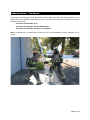
Securing The Ladder – Footing
Introduction: A ladder is to be kept from slipping whenever a firefighter is climbing it- no exceptions!
There are several methods employed by the Henderson Fire Department when footing a ground ladder.
When securing a ladder, the firefighter must be wearing a helmet and gloves, and must not look up.
Debris from the building or from the firefighters working area is always considered a hazard.
Method 1: Positions yourself beneath the raised ladder with your back toward the building. Stand with
feet about shoulder width apart, span the beams of the ladder with both hands around eye level, and
pull backward pressing the ladder against the building.
Method 2: In the second method of footing, the firefighter footing the ladder places the toes of one foot
against the base of the ladder at the shoes. The hands span the beams and the ladder is pressed against
the building.
Ladders | 10
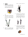
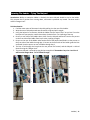
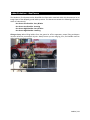
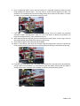
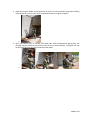
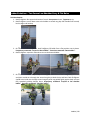
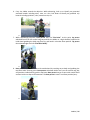
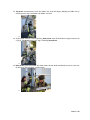
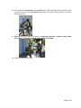
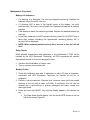
Securing The Ladder – Tying The Halyard
Introduction: Before an extension ladder is climbed, the excess halyard should be tied to the ladder.
This prevents the fly section from coming down, and avoids a potential trip hazard. The knot used is
called a “Bangor Knot”.
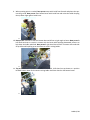
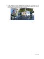
Task Benchmarks:
1. Find the center point of the excess halyard by pulling it to the rear of the ladder.
2. Wrap the excess halyard around two convenient rungs and pull it taught.
3. Using the halyard as a reference, divide the ladder into four equal “bays” at eye level. From the
base person’s perspective, number these bays clockwise from 1 to 4 starting at the top.
4. Person on rear side of the ladder takes a bite from the halyard and feeds it back to the person
on the front side of the ladder from bay 3 to bay 1 pulling it taught.
5. Person on the rear of the ladder takes another bite of the halyard and feeds it to the person on
the front side of the ladder through bay 3. Person on the front side of the ladder grabs the bite
and feeds it back to person on rear of ladder through bay 2.
6. The bite is fed through the loop that the rear person has formed, and the halyard is cinched
down forming the “Bangor Knot”.
7. The excess halyard is secured by tying hitches around itself. Remember: bays 3 to 1 and 3 to 2
will form the Bangor Knot. “31 32 Follow Through”.
1.
4.
2.
5.
3.
6.
7.
Ladders | 11
Climbing Ladders – General Technique
Introduction: Firefighters ascending or descending a ladder should make sure they do so as smooth as
possible. This is accomplished when the climber keeps the knees bent and eases weight onto each rung.
Attention should be focused on causing the least amount of bounce or sway when climbing the ladder.
Climbing may start after the climbing angle has been checked and the ladder is properly footed. The
firefighter climbing notifies the person footing the ladder that they are about to begin climbing by
saying: “On Ladder”.
Climbing Technique: As the firefighter ascends the ladder, eyes should be focused straight forward with
an occasional glance toward the destination. The firefighter’s arms should be kept straight during the
climb which will help keep the body away from the ladder. The hands should grasp the rungs with palms
down and thumbs beneath the rung. The climb should be done smoothly and rhythmically with all
upward progress being accomplished by the leg muscles, not the arm muscles. The arms and hands
should not reach upward during the climb. Reaching upward will bring the climber’s body too close to
the ladder. Once the firefighter reaches the destination and dismounts the ladder, notify the person
footing the ladder by saying: “Off Ladder”.
Ladders | 12
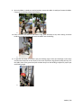
Climbing Ladders – Working on a Ladder
Introduction: Whenever firefighters must perform work from a ground ladder they are to secure
themselves to the ladder by using a leg lock. The Henderson Fire Department refers to this leg lock as
“locking-in”.
Technique: To lock-in on a ladder, the firefighter climbs to the desired height of the ladder. Then stands
with both feet on a common rung and raises the opposite leg to the side the work will be on. This leg is
lifted over the second rung from the common rung that the firefighter is standing on, and placed
through that rung bay. The leg is then brought back through the ladder just below the rung that is
supporting the knee. This foot is then wrapped around the top side of the beam. The other foot is
placed against the opposite beam for stability. The firefighter is now locked in to the ladder and is able
to work hands free.
Note: Individual body mechanics and body structure will dictate exactly how a firefighter will accomplish
the lock-in. A firefighter with long or short legs may need to alter this procedure for safety and comfort.
Ladders | 13
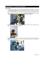
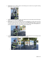
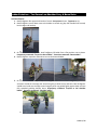
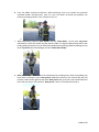
Ladder Evolutions – One Person
The Henderson Fire Department has identified the information contained within this document to be an
integral part of the adopted ground ladder practices. This document contains the following information
within its subsection(s).
One Person Low Shoulder- Carry & Raise
One Person Low Shoulder- Lowering
One Person High Shoulder- Carry & Raise
One Person High Shoulder- Lowering
Lifting to Carry: When lifting ladders from the ground or off the apparatus, proper lifting techniques
must be utilized to prevent back injuries. Always ensure you are using leg, arm, and shoulder muscles
while keeping your back straight.
Ladders | 14
Ladder Evolutions – One Person Low Shoulder Carry & Raise
Task Benchmarks:
1. From the grounded position: face opposite the direction of travel at the balance point of the
ladder. Usually, this will mean facing the tip of the ladder.
2. Crouch down next to the ladder with the outside foot forward, back straight, and head up. Using
the inside hand grab the beam at the balance point of the ladder.
a.
3. Lift the ladder from a flat position onto its beam.
a.
4. Reposition body next to the ladder with the inside hand grabbing the beam at the balance point.
a.
5. With the ladder in a beamed position: lift the ladder from the ground and rotate body 180°
placing the outside arm through the rungs at the balance point. Firefighter will now be facing
the base of the ladder.
Ladders | 15
6. Prior to advancing ladder, ensure that the inside arm is extended straight out with the inside
hand grabbing the bottom beam. The rung shall be tucked securely against the body. The
outside arm is extended with the outside hand grabbing the top beam of the ladder. For safety
to others, carry the ladder with the base below eye level.
a.
7. Carry the ladder toward the objective. While advancing, look up to identify any potential
overhead hazards including wires, trees, etc. Also, look down to identify any potential trip
hazards including sprinklers, curbs, uneven terrain, etc.
8. While approaching the objective, place the outside hand, thumb down, on the rung in front of
the inside shoulder, with hand all the way at top of the rung.
9. Shift inside hip against the lower beam of the ladder.
10. While in this position, pass inside arm through rung bay and grab the rung that is against the
inside shoulder with the inside hand, thumb up and hand all the way at the bottom of the rung.
a.
11. If needed, use inside hip to “pop” the ladder up and away from the body while simultaneously
raising inside arm until ladder is in a flat position. Shift the ladder forward until the ladder is
resting on the upper most part of the shoulder and dip the base toward the ground.
a.
Ladders | 16
12. As the ladder base contacts the building at ground level, slightly squat down with the knees. As
the knees are straightened, push the ladder off the shoulder and continue to raise the ladder to
vertical. Make sure to grab the center of the rungs as it is being raised into the building. Once
the tip of the ladder contacts the building, place one foot on the center of the bottom rung.
a.
13. To position the ladder at a proper spot and climbing angle: Place one hand high on the beam
and the other hand low on the center of the most convenient rung (bottom hand palm up). Lift
the ladder clear of the ground and pull the base away from the building to adjust for proper spot
and climbing angle.
a.
14. Squat down with the knees and secure the ladder.
a.
15. Ladder is now ready for use.
Ladders | 17
Ladder Evolutions – One Person Low Shoulder Lowering
Task Benchmarks:
1. To lower the ladder flat: place one hand high on the beam and the other hand low on the center
of the most convenient rung (bottom hand palm up). Lift the ladder clear of the ground and
push the base against the building. As the base contacts the building place one foot on the
center of the bottom rung.
a.
2. Check to ensure the area needed for lowering ladder is clear. The area directly above the tip will
also be checked. Firefighter will indicate the area is clear by shouting “All Clear”.
a.
Ladders | 18
3. Begin lowering the ladder by placing hands on center of most convenient rungs while walking
back towards tip; ensure every rung is contacted and that no rungs are skipped.
a.
4. Once the balance point is reached, pivot body 180° while simultaneously placing free arm
through rung bay. Allow the top beam to come to rest on inside shoulder. Firefighter will now
be facing the direction of travel and the tip of the ladder.
a.
Ladders | 19
Ladder Evolutions – One Person High Shoulder Raise
Task Benchmarks:
1. From the grounded position: face opposite the direction of travel at the balance point of the
ladder. Usually, this will mean facing the tip of the ladder.
2. Crouch down next to the ladder with the outside foot forward, back straight, and head up. Using
the inside hand grab the beam at the balance point of the ladder.
a.
3. Lift the ladder from a flat position onto its beam.
a.
4. Reposition body next to the ladder with the inside hand grabbing the beam at the balance point.
a.
5. With the ladder in a beamed position: lift the ladder from the ground and rotate body 180°
placing inside hand beneath the bottom beam at shoulder level. Rest the bottom beam of the
ladder on the hand not directly on the shoulder. Grasp the top beam of ladder with the outside
hand making sure it is positioned slightly forward in relation to the inside hand. If the top beam
cannot be reached comfortably by the outside hand, it is permissible to grasp a rung.
a.
Ladders | 20
6. Carry the ladder toward the objective. While advancing, look up to identify any potential
overhead hazards including wires, trees, etc. Also, look down to identify any potential trip
hazards including sprinklers, curbs, uneven terrain, etc.
a.
7. When desired spotting point is reached, lower the base of the ladder, bend at the knees and dip
making sure back is straight and head is up. Plant the bottom beam ladder spur into the ground.
a.
8. Push ladder off the shoulder with inside hand and arm while simultaneously straightening legs.
a.
Ladders | 21
9. Once the ladder is raised to a vertical position, ensure the ladder is steady and rotate the ladder
if necessary by footing a beam and rotating.
a.
10. Place a foot on the center of the bottom rung, span the beams at eye level making sure both
hands are up against beams and lower the ladder into the building.
a.
11. To position the ladder at a proper spot and climbing angle: Place one hand high on the beam
and the other hand low on the center of the most convenient rung (bottom hand palm up). Lift
the ladder clear of the ground and pull the base away from the building to adjust for proper spot
and climbing angle.
a.
Ladders | 22
Ladder Evolutions – One Person High Shoulder Lowering
Task Benchmarks:
1. To lower the ladder on a beam: Place a foot on the center of the bottom rung and span the
beams at eye level with both hands.
a.
2. Call “All Clear” prior to pulling the ladder away from the building. Using a counter balance of
bodyweight, pull the ladder tip away from the building until it reaches vertical.
3. Once the ladder is vertical, rotate the ladder if necessary by footing a beam and rotating the
ladder 180°.
a.
4. Place hand on the beam balance point or as close to it as possible. Span the opposite beam with
other hand. Step beneath what will become the bottom beam and call “All Clear”. Let the
ladder fall onto shoulder while simultaneously bending at the knees and dipping, allowing the
ladder to come to rest at shoulder level (Keep back straight and head up), straighten legs, and
come to a standing position. Carry the ladder as prescribed.
a.
Ladders | 23
Ladder Evolutions – Two Person
The Henderson Fire Department has identified the information contained within this document to be an
integral part of the adopted ground ladder practices. This document contains the following information
within its subsection(s).
Two Person Low Shoulder- Carry
Two Person Low Shoulder- Flat Raise/Beam Raise
Two Person Low Shoulder- Lowering on a Flat/Beam
Note: The Henderson Fire Department Follows the IFSTA recommendation of one Firefighter per fly
section.
Ladders | 24
Ladder Evolutions – Two Person Low Shoulder Carry & Flat Raise
Task Benchmarks:
1. Both firefighters face opposite direction of travel. Base person at base, Tip person at tip.
2. Both firefighters crouch down next to the ladder at second rung bay with outside foot forward,
back straight and head up.
a.
3. On command from base person, both firefighters lift ladder from a flat position onto its beam.
Preparatory command: “Prepare to beam ladder”. Execution command: “Beam Ladder”.
4. Both firefighters reposition themselves next to the beamed ladder.
a.
5. On command from the base person, both firefighters lift the ladder from the ground, pivot 180°
and place outside arm through the second rung bay at both the tip and base. Both firefighters
should have inside arms through second rung bay with rung pulled tightly against body and arm
fully extended grabbing bottom beam. Preparatory command: “Prepare to low shoulder
ladder”. Execution command: “Shoulder ladder”.
a.
Ladders | 25
6. Carry the ladder toward the objective. While advancing, look up to identify any potential
overhead hazards including wires, trees, etc. Also, look down to identify any potential trip
hazards including sprinklers, curbs, uneven terrain, etc.
a.
7. While approaching objective, base person calls out “Flat Raise”. At this point, tip person
withdraws arm from the second rung bay and lifts the ladder to a high shoulder position with
inside hand grabbing the third rung from tip, and hand in a thumbs down position. Tip person
then acknowledges and calls “Flat Raise Ready”.
a.
8. Base person supports the ladder with outside hand by reaching across body and grabbing the
top beam while covering spurs. Base person withdraws inside arm from the second rung bay
and positions inside hand to grab the top beam. Base person lets go of spurs with outside hand
and lets inside arm drop to full extension. The base person is now in a suitcase position/carry.
a.
Ladders | 26
9. When the spotting point is reached, base person steps with the inside foot forward and plants
the ladder spur into the ground.
a.
10. Base person foots ladder with inside foot by stepping on spur while simultaneously rotating
180° while flipping ladder away from body using left hand (fly section on the outside). Base
person then transitions right foot from the spur onto the bottom rung. Then places left foot on
bottom rung, and begins to stand up and “ride rung” as the ladder is being raised to vertical.
Base person can place hands on convenient beams or rungs.
a.
Ladders | 27
11. Tip person simultaneously raises the ladder over head and begins walking the ladder tip up
ensuring every rung is contacted until ladder is vertical.
a.
12. As the ladder reaches a vertical position, base person steps off the bottom rung and moves into
a “big X”. Tip person moves into “big X” following base person.
a.
13. Base person grabs the halyard with both hands, thumbs down and elbows out, then raises the
fly section to desired height, and locks dogs.
a.
Ladders | 28
14. On command from base person, the tip person spans beams with both hands and places a foot
on center of bottom rung. Base person spans beams with both hands and takes a step back
towards objective.
a.
15. Tip person guides the ladder into objective. Preparatory command: “Prepare to lower ladder
into building”. Execution command: “Lower ladder into building”.
a.
16. Ladder is tied off as prescribed.
Ladders | 29
Ladder Evolutions – Two Person Lowering Flat
Task Benchmarks:
1. Prior to pulling the ladder away from the building, base person calls “All Clear”. On command
from Base person, tip person spans beams with both hands and places a foot on the center of
bottom rung. Base person spans beams and takes a step forward while pushing the ladder away
from the objective until ladder reaches vertical. Preparatory command: “Prepare to remove
ladder from building”. Execution command: “Remove ladder from building”.
a.
2. Base person grabs the halyard with both hands, thumbs down elbows out, and lowers the fly
section until fully retracted, and locks the dogs.
a.
3. Base person calls “All Clear” places both feet on the bottom rung, grabs convenient rung/beams
with both hands, and begins to lower ladder while pulling back to take as much weight as
possible from the tip person.
a.
Ladders | 30
4. Tip person lowers the ladder hand over hand making sure to contact every rung until reaching
the second to last rung at the tip.
a.
5. Tip person brings the ladder to shoulder and holds free arm out horizontally while still facing the
base. This acts as a signal to the base person.
6. Base person steps to side of the ladder as directed by tip person’s arm signal, grabs the outside
beam with inside hand and lifts the ladder onto its beam. Base person then places outside hand
on third rung from base with thumb against the top beam and lifts ladder. Base person then
places inside arm through the second rung bay from the ladder base.
a.
7. As the base person lifts ladder, the tip person rotates 180° and places free arm through second
rung bay from the tip. Firefighters carry ladder as prescribed.
a.
Ladders | 31
Ladder Evolutions – Two Person Low Shoulder Carry & Beam Raise
Task Benchmarks:
1. Both firefighters face opposite direction of travel. Base person at base, Tip person at tip.
2. Both firefighters crouch down next to the ladder at second rung bay with outside foot forward,
back straight and head up.
a.
3. On command from base person, both firefighters lift ladder from a flat position onto its beam.
Preparatory command: “Prepare to beam ladder”. Execution command: “Beam Ladder”.
4. Both firefighters reposition themselves next to the beamed ladder.
a.
5. On command from the base person, both firefighters lift the ladder from the ground, pivot 180°
and place outside arm through the second rung bay at both the tip and base. Both firefighters
should have inside arms through second rung bay with rung pulled tightly against body and arm
fully extended grabbing bottom beam. Preparatory command: “Prepare to low shoulder
ladder”. Execution command: “Shoulder ladder”.
a.
Ladders| 32
6. Carry the ladder toward the objective. While advancing, look up to identify any potential
overhead hazards including wires, trees, etc. Also, look down to identify any potential trip
hazards including sprinklers, curbs, uneven terrain, etc.
a.
7. While approaching objective, base person calls out “Beam Raise”. At this point, tip person
withdraws arm from the second rung bay and lifts ladder to a high shoulder position with inside
hand grabbing the bottom of main beam and outside hand supporting ladder by holding the top
beam. Tip person then acknowledges and calls “Beam Raise Ready”.
a.
8. Base person supports the ladder with outside hand by reaching across body and grabbing top
beam while covering the spurs. Base person withdraws inside arm from second rung bay and
positions inside hand to grab the top beam. Base person lets go of spurs with outside hand and
lets inside arm drop to full extension. Base person is now in a suitcase position/carry.
a.
Ladders| 33
9. When spotting point is reached, base person steps with inside foot forward and plants the spur
into the ground. Base person foots bottom beam with inside foot and raises the ladder keeping
the top beam tight against inside knee.
a.
10. Base person continues to foot the bottom beam with foot at right angle to beam. Base person’s
left hand continues to remain in contact with the beam while applying downward pressure to
help keep the ladder stabilized. Base person’s right hand also remains in contact with underside
of top beam while pulling up on the beam to assist in raising ladder.
a.
11. Tip person raises the tip over head with both hands, shifts hand on top beam to a position
beneath bottom beam and continues raising ladder hand-over-hand on the bottom beam.
a.
Ladders| 34
12. When the ladder is vertical, base person removes foot from beam, moves into base position
creating a “big X.” Tip person moves into tip position and also moves into “big X.”
a.
13. Base person, grabs the halyard with both hands thumbs down and elbows out, raises the fly to
the desired height, and locks dogs.
a.
14. On command from base person, tip person spans beams with both hands and places a foot on
the center of the bottom rung. Base person spans beams with both hands and takes a step back
towards objective. Tip person guides the ladder into the objective. Base person states
Preparatory command: “Prepare to lower ladder into building”. Execution command: “Lower
ladder into building”.
a.
15. Ladder is tied off as prescribed.
Ladders| 35
Ladder Evolutions – Two Person Low Shoulder Lowering on a Beam
Task Benchmarks:
1. Prior to pulling ladder away from building, base person calls “All Clear”. On command from
Base person, tip person spans the beams with both hands and places a foot on the center of
bottom rung. Base person spans beams and takes a step forward while pushing ladder away
from objective until ladder reaches vertical. Preparatory command: “Prepare to remove ladder
from building”. Execution command: “Remove ladder from building”.
a.
2. Base person grabs the halyard with both hands, thumbs down elbows out, and lowers fly
section until fully retracted and locks dogs. Firefighters pivot ladder if necessary.
a.
3. Base person calls “All Clear” and then foots the beam that the ladder will be lowered on. Tip
person grabs both beams of the ladder for balance.
a.
Ladders| 36
4. Tip person places both hands beneath the bottom beam as the ladder is lowered. Base person
grabs the top beam with both hands and pulls the ladder back to offset its momentum, while
keeping the top beam tight against knee.
a.
5. Base person stops tip person at the second rung bay from the tip by calling “tip person high”.
Tip person then brings the ladder to a high shoulder position.
a.
6. Base person steps to the side of the ladder, places outside hand on third rung from base with
thumb against top beam and lifts the ladder. Base person then places inside arm through the
second rung bay from the base.
a.
Ladders| 37
7. As base person lifts the ladder, tip person drops the ladder into a low shoulder carry, and
rotates 180° and places outside arm through the second rung bay. Tip person is now facing the
tip of the ladder. Firefighters carry the ladder as prescribed.
a.
Ladders| 38
Ladder Care & Maintenance
The Henderson Fire Department has identified the information contained within this document to be an
integral part of the adopted ground ladder practices. This document contains the following information
within its subsection(s).
Aluminum Ladders General Information
Care and Maintenance
Care and Maintenance- Special Types of Ladders
The Henderson Fire Department uses heat treated aluminum 6061-T6 alloy ground ladders. Three
principal reasons for using aluminum are: it is light weight, has adequate strength, and it permits for an
accurate and reliable visual inspection of all ladder parts.
There is one major disadvantage in using aluminum for fire department ground ladders. Aluminum is an
excellent conductor of electricity, which poses a great risk to firefighters working with ladders around
overhead wires. Extreme caution must be used whenever ladders are being operated around electrical
power sources.
Care and Maintenance
The proper care and maintenance of fire department ground ladders is imperative to their longevity,
ease of handling, and reliability. Regular and proper cleaning of ladders is more than a matter of
appearance. Dirt, road dust, or debris from a fire can collect on a ladder and make the ladder sections,
hooks, pulleys, etc. inoperable. They should be cleaned and inspected after each use and pulled off of
the apparatus every Monday to be inspected and/or cleaned.
Tested, cleaned, and maintained ladders last longer. Properly lubricated ladder sections slide easier and
simply work better. No ladder should require more than a 75 lb. pull to raise any section. If you have any
ladder in service that seems to require more than a 75 lb. pull to raise, immediate cleaning and waxing
of all contact surfaces and lock parts should take place.
All stops, dogs, halyards, rivets, pulleys, and all moveable parts should be examined. The moveable parts
should be lubricated every six months. The old lubricant should be removed with a solvent prior to
applying the new one.
DUO-SAFETY LADDER suggests plain old candle wax or paraffin wax as your best lubrication. This wax
coats and works into the pores of the ladder material and does not easily wash away with frequent
water baths. This candle wax is also not costly and is readily available anywhere. It is suggested that you
extend the ladder, and simply rub the candle wax over and onto all of the contacting parts.
CLEANING: Mild soap (ex: Ivory dish soap) and water works well - be sure to flush inside the rails and
rungs to clear them of road salts, etc. We suggest a plastic scrub pad to buff the surface to a smooth
finish. Be sure to clean and rewax the slide areas at the same time.
Be sure to check any heat sensor labels as you clean and wash the ladder. Try not to wash away the
labels. NOTE: Use of harsh soaps or chemicals can sometimes turn heat sensor labels dark that is why
mild soap is recommended for cleaning.
Ladders | 39
RAILS AND RUNGS: Aluminum is a malleable metal and is subject to dents and nicks, etc. NOTE: Small
dents and/or nicks on the beams and rungs are not uncommon and are not grounds to fail a ladder. Be
sure to record the location and size for future reference.
If there is ever any question or concern about any major dent(s) or other damage, the ladder should be
removed from service and load tested. Be sure the rungs are all tight as the rung to rail joint is the only
thing that holds the two beams together. If any rung is loose - remove the ladder from service, have it
repaired and service tested before further use.
Care and Maintenance- Special types of Ladders
ROOF HOOKS: Fire service roof ladders are supplied with spring loaded, directionally swiveling and
locking hook assemblies capable of 1,000 lb. load per hook/2,000 lb. load per pair. The roof hooks
normally only require occasional cleaning to maintain proper operation - mild soap and water works
well
FOLDING LADDERS: Maintenance is again the same as the general maintenance covered earlier. Mild
soap and water works well for cleaning purposes. Ensure you check the rung assembly rivets regularly to
be sure they are not worn excessively.
A-FRAME/COMBINATION LADDERS- LITTLE GIANT LADDER: Be sure to inspect the hinge hardware and
fasteners. A few drops of any type of oil works well on the hinges and of course, soap and water works
well on all the other parts. Be sure to check the spreader arms, bars and parts to be sure everything still
works and fits together properly. These parts are vital in the A-frame position and must be able to
properly engage before the ladder would be safe to use in the A-frame position.
Ladders | 40
Chapter
6
Equipment Guidelines
The purpose of the Henderson Fire Department Equipment Guidelines is to provide a standardized
series of documents to guide department members in the safe, consistent use and maintenance of fire
ground equipment and tools. The guidelines define the standardized use that shall be adopted by all
Fire/Rescue Operations Personnel. The safe use of all equipment contained in the Equipment Guidelines
shall be in conjunction with already established department Standard Operating Procedures, Task
Standards, and Administrative Directives.
Chapter
6
Equipment Guidelines Table of Contents
•
•
•
•
•
•
•
•
•
•
•
•
•
•
•
•
•
•
EG-01
EG-02
EG-03
EG-04
EG-05
EG-06
EG-07
EG-08
EG-09
EG-10
EG-11
EG-12
EG-13
EG-14
EG-15
EG-16
EG-17
EG-18
Motorola Radio
SCBA
TIC
Ground Ladders
Hand Tools maintenance
Portable Gas Blower
Extinguishers
Chain Saw
K12
Reciprocating Saw
Amkus
PRO/pak
In-Line Eductor
Vehicle Access Kit
Gas Tracer
Radiation Monitor
pH/F paper
Temp Gun
Firefighter Equipment Guideline – 01
Motorola XTS 5000R Portable Radio
Goal: To provide an Equipment Guideline Standard to ensure safe, consistent
operation and maintenance of the Motorola XTS 5000R portable radio, as well as
assure continued monitoring and operation of portable radios.
Level of Training: All Fire/Rescue Operations Personnel
Definitions:
PTT: Push To Talk button is the large black button on the left side of the radio
Soft Keys: The three dot soft keys, also known as the menu select buttons select
the function shown over them on the display
Emergency Button: The emergency button is the orange button located at the
base of the radio antenna. Depressing the emergency button will alert Control
and give you priority sending your radio traffic.
Operations:
•
•
•
•
•
•
•
Effective communication is critical for the safety and success of our personnel
while delivering emergency services to our community. Effective on scene
communication provides the connection between the Strategic level IC, the
Tactical level Division/Groups, and the Task level of the workers. In order to
standardize and clarify the communications process the following procedures
will be followed per HFD SOP EM-38 Communications.
Personnel shall carry and monitor their radio at all times when out of the
station.
Fire Administration shall monitor as needed. All portable radios are to remain
as issued.
Alterations and accessories must be approved by the Logistics Chief.
Radios must be turned off during battery removal and installation, according
to the manufacturer’s instructions.
In the event a portable radio has been immersed or extensively exposed to
water (or any other liquid), the unit should be turned off and the battery
removed immediately to stop corrosion to the circuits (see Item I.)
Portable radios and/or its accessories damaged or not working properly shall
be reported to the on duty Battalion Chief for replacement.
EG-01 | 1
•
•
If a radio and/or its accessories is lost or stolen, it must be reported
immediately to the on duty Battalion Chief. An official report must be
completed. Once the radio and/or accessories have been replaced by the
Battalion Chief the equipment will be turned over to the Logistics Division
Chief for replacement or repair.
The 800 mhz fleet maps shall be kept current by the Logistics Division and
can be found by contacting them.
General Requirements
•
•
•
•
•
•
•
Standard Language: Clear text will be used. Codes will be avoided if
possible.
Radio Communication Techniques: Before transmitting know what you are
going to say. Personnel must use a calm clear voice. Speak slowly and
position your mouth 1-3 inches away from the radio.
Be concise: Only utilize radio traffic for pertinent information. Prioritize your
messages. Do not use up valuable air time with unimportant messages and
insignificant details.
Transmit critical messages first.
Do not interrupt unless you have
“Emergency Traffic”.
Radio Communication Format: The HFD will utilize the “Hey you, it’s me”
format.
Order Model: Along with the “Hey you it’s me” format, the Order Model will
also be followed. The Order Model states that before a message is sent the
receiver must indicate they are ready to listen, and then after it is given they
must briefly restate the message to insure clarity.
Radio Etiquette: A professional and courteous demeanor will be maintained
during radio communication. Foul language, sarcasm, insults and horseplay
will not be allowed. The primary channels of Z7 B9 and TAC 3 will not be
utilized for any communication outside of emergency operations and official
fire department business.
EG-01 | 2
Radio Channels
•
•
•
•
•
•
•
HFD primary dispatch/communication channel is Zone 7 Battalion 9
Zone 7 Tac 3 will be the first tactical channel utilized for significant incidents.
All units dispatched on first alarm assignments will be advised to switch to Z7
Tac 3.
The IC or dispatch can request to switch communications to Z7 Tac 3 on any
incident that is escalating and creating communication difficulty on the primary
channel.
The additional Tactical Channels that can be utilized by the IC are: Tac 4 – 9.
Zone 7 Battalion 9 is the main channel to be monitored by on-duty personnel.
All Fire/Rescue Operations personnel assigned a portable radio shall monitor
radio transmissions from 0700 until 2100.
Maintenance Procedures
Battery
•
•
•
Batteries have an 8 hour battery life
Change batteries daily each morning
Clean radio with department approved cleaners
Equipment Specs
Motorola XTS 5000R
•
•
•
•
•
•
Frequency band: VHF, UHF, 700 MHz, and 800 MHz capable
Battery: Nickel Cadmium with 8 hour life
Weight: 21.6 oz
1000 channel capability
Adheres to military specs 810 C, D, E, F allowing resistance to drops,
vibrations, shock, and static electricity.
IP54: Submersible and dust protected
EG-01 | 3
Firefighter Equipment Guideline – 02
Dräger Self-Contained Breathing Apparatus (SCBA)
Goal: To provide an Equipment Guideline Standard to ensure safe, consistent
operation and maintenance of the SCBA. It is the policy of the Henderson Fire
Department that all personnel expected to, or likely to, respond to and function in areas of
atmospheric contamination will be equipped with and trained in, the proper use and
maintenance of the self-contained breathing apparatus.
Level of Training: All Fire/Rescue Operations Personnel
Definitions:
PASS: The Personal Alert Safety System is a device that emits a loud alert or
warning that the wearer is motionless.
HUD: The Heads-Up Display found in the face mask provides a visual display of
air cylinder PSI through the use of green, yellow, and red lights.
Sentinel: The Dräger 7000 utilizes the Sentinel 7000 as a fully integrated
pressure gauge, smart electronic monitoring device, and PASS device providing
real time information about the SCBA to the user every 30 seconds.
Lung Demand Valve: The Lung Demand Valve (LDV) also known as the second
stage regulator completes the connection between the SCBA and face mask,
and further reduces the high pressure to positive pressure slightly above
atmospheric pressure.
Responsibility: Members are responsible for checking their SCBA and PASS alarm on a
daily basis and after every use. Spare SCBAs are the responsibility of the unit
Driver/Engineer. All personnel shall be familiar with the proper methods of cleaning
all SCBA components in accordance with manufacturer’s policies.
Safety Operations
•
•
•
SCBAs will be worn by all Fire/Rescue Operations personnel entering an IDLH or
potentially IDLH atmosphere and/or when determined by the officer in charge. The
SCBA will NOT be removed after the fire is extinguished until the officer in charge
determines the structure is clear of smoke and toxic products.
All personnel will exit the hazardous environment before the point at which
remaining operation time of breathing apparatus equals the time necessary to
return safely to a nonhazardous environment.
Face mask fit testing will be conducted in accordance with OSHA 1910-134.
EG-02 | 1
•
Personnel who must wear glasses while using SCBA shall have their face mask
equipped with a spectacle kit.
Task Benchmarks
Donning Procedure
•
•
Perform a proper Daily Check prior to donning the SCBA.
The process to don the SCBA shall be in accordance with HFD IPS-02
Donning SCBA Task Standard.
Maintenance Procedures
General
•
•
•
•
•
The SCBA is the most critical piece of firefighting equipment used.
The SCBA shall be inspected for defects daily, immediately after use, and
weekly (Monday) in accordance with manufacturer’s guidelines.
Utmost care shall be exercised in the maintenance, cleaning, storage, and
handling.
Repairs by members are limited to the replacement of voice amplification and
heads-up display batteries.
All other repairs or adjustments must be done by the HFD Equipment
Technician.
SCBA Face Mask
•
•
•
•
•
Check the face mask head straps/head harness for cuts, pliability, and
integrity.
Inspect the face mask lens for cracks or large scratches.
Ensure the lens and second stage regulator connection is free of dirt and
dust.
Ensure the HUD connection when turned on and lights illuminate
appropriately.
Check that the voice amplifier works with full battery.
EG-02 | 2
SCBA Air Cylinder
•
•
•
•
Check the exterior of the cylinder for nicks, cuts, gouges, and heat damage.
Check air pressure indicators on each side of the cylinder valve.
The PSI should read within 500 PSI of each other.
If the air cylinder gauge reads less than 4000 PSI as indicated on the
Sentinel, replace with a fully pressurized cylinder.
SCBA Harness and Backplate
•
•
•
•
Check straps, harness, padding, buckle and backplate for damage, cracks,
defective buckle.
Ensure proper backplate height adjustment.
Ensure shoulder and waist straps are in a position of readiness.
Ensure central battery pack is connected.
Sentinel 7000
•
•
•
•
•
•
Check for Sentinel activation when system is pressurized.
Check battery life: Visual check of battery life on bar graph during initial start
up.
Change battery pack in back plate if below 50% battery life.
Check digital pressure readout for accuracy.
Check for PASS alarm and full alarm activation is functioning properly with
both visual and audible alarms.
Ensure 50% and 25% alarms sound as system pressure is relieved.
Regulator, Hoses, and Buddy Breathing Connection
•
•
•
•
Check hoses for holes, cuts, tears, rust or corrosion.
Check quick connect couplings for proper function.
Check second stage regulator (LDV) for damage or cracks to housing. Check
knobs and buttons for proper operation. Test connection and release from
face mask.
Check buddy breathing fittings for leaks while pressurized, caps in place and
hose stored correctly.
EG-02 | 3
Dräger SCBA Daily Check
•
•
•
•
•
•
•
•
•
•
•
•
•
•
•
•
•
•
•
SCBA should be in front of you, out of apparatus mounting bracket.
Check air cylinder pressure. Pressure should not be lower than 4000 PSI.
Check for proper connection of the cylinder to the first stage regulator quick
connect.
Open air cylinder valve slowly and listen for audible whistle as system is
pressurized. The Sentinel will also flash/audiblize.
Check battery life and digital pressure readout on Sentinel. Match pressure
gauge on cylinder and Sentinel.
Don face mask and ensure HUD activation.
Check second stage regulator shut off button is depressed, and bypass valve
is off.
Attach LDV to face mask and try to pull it out.
Perform a negative pressure test.
Ensure first breath on activation provides positive pressure with no excessive
free flow of air past the face mask.
Check proper bypass function.
Hold breath and listen for mask leak.
Depress shut off button and remove LDV from mask and replace in holster.
Close air cylinder valve and observe Sentinel digital pressure readout for any
drop in pressure.
Slowly open the bypass valve to bleed the system. As the pressure drops
observe the Sentinel to ensure the alarms function at 50% and 25% of air
cylinder pressure as well as audible whistle from the first stage regulator
when cylinder reaches less than 25% PSI.
Hold at 500 – 1000 psi and listen for continuous EOST alarms, then bleed
pressure to 0 PSI.
Wait 30 seconds for Full PASS alarm activation. Reset alarm, and then
check manual PASS activation.
Check harness and backplate and reset shoulder and waist straps for
readiness.
Secure SCBA to bracket.
EG-02 | 4
Cleaning/After Use Care
•
•
•
If the SCBA is still serviceable, steps must be taken to ensure readiness prior
to placing it back on the apparatus.
Face mask
o Rinse mask in water after each use
o Use baby soap if further cleaning is needed
o WARNING!: AIR DRY ONLY, NO COMPRESSED AIR.
SCBA Pack
o Ensure the LDV is in its holder with doffing button depressed.
o Ensure the cylinder is attached to first stage regulator and back plate.
o Use cool water and baby soap as needed.
o Air dry.
o Perform a Daily Check.
o Perform a High Pressure Leak Test.
Weekly (Monday) Check
•
•
•
Perform a Daily Check
Perform a High Pressure Leak Test
1. Ensure cylinder is off, doffing button is depressed and no pressure is in
the lines.
2. Press the left button on the Sentinel.
3. When the high pressure leak test icon is displayed press the left button
again.
4. Open cylinder valve when icon is displayed.
5. Close cylinder valve when icon is displayed.
6. Press right button.
7. After test pass through icon is displayed press right button.
8. Test complete.
If the pack does not pass retest, if it does not pass a second time, place the
pack out of service.
EG-02 | 5
Equipment Specs
Dräger PSS 7000 SCBA
•
•
•
•
•
•
•
Advanced compression-molded comfort padding
Carbon fiber composite back plate
Three height adjustments
10 second air cylinder quick connect/disconnect
Sentinel 7000 provides real time information to the user every 30 seconds
Both the Dräger PSS 7000 SCBA and the Sentinel 7000 are powered by one
central quick change battery pack system with five AA batteries, with an
additional CR-123 backup battery
Utilizes 4500 PSI high pressure 45 min. bottle
References
•
•
•
•
Equipment Operations Handbook, Chapter 3 SCBA
Dräger PSS 7000 User manual
Hendersonfireonline.com Dräger SCBA training links
HFD Administrative Directive Self-Contained Breathing Apparatus
EG-02 | 6
Firefighter Equipment Guideline – 03
ELITE XR Thermal Imager
Goal: To provide an Equipment Guideline Standard to ensure safe, consistent
operation and maintenance of the thermal imager.
Level of Training: All Fire/Rescue Operations Personnel
Definitions:
Electro-optical: The ELITE XR is a complex electro-optical device that uses an
electric field with light traversing it to produce images. Electronic systems are
subject to potential failures. If a failure occurs, the user will no longer have
access to the thermal images provided by the ELITE XR.
Intrinsically Safe: The ELITE XR is not rated as intrinsically safe. Do not use
the system in environments or atmospheres where static or a spark will cause
explosion.
Digital Direct Temperature (DDT): The DDT provides the average relative (or
“observed”) temperature of an object, or objects within the crosshairs. The
relative temperature is displayed in numerical form in the upper right hand corner
of the viewing screen. DDT is operational at all times and cannot be switched on
or off.
Sense Mode: Sometimes called a sensitivity mode, or gain mode is similar to the
exposure compensation controls in a typical digital camera. The ELITE XR
senses heat instead of light. The XR will automatically select what it thinks is the
most appropriate sense mode.
High Sense Mode (H): This mode is automatically activated by the ELITE XR
when objects in its field of view are at room temperature or cooler.
Mid Sense Mode (M): This mode is automatically activated by the ELITE XR
when objects in its field of view are generally greater than 150°F.
Thousand Plus Mode (EI+): This mode is automatically activated by the ELITE
XR whenever the crosshair in the center of the viewing screen is directed to
objects that are generally greater than 450 – 475°F. While in this mode the
ELITE XR is capable of imaging objects that are in excess of 2000°F.
Intelligent Focus Override: Increases the usefulness of a thermal imager by
giving the firefighter control over the camera’s default sensitivity (sense) mode
settings.
EG-03| 1
Emissivity: An object’s emissivity is its ability to either absorb or reflect heat
energy. The better the characteristic to absorb heat (the higher the emissive
value), and generally the more accurate the temperature reading.
Safety Operations
•
•
•
•
•
•
•
•
•
The following safety equipment shall be used in conjunction with the ELITE
XR fire ground operations at all times:
1. Structural Firefighting PPE
2. SCBA
All users must be thoroughly trained on the ELITE XR proper operation,
features and full functionality prior to use. This includes general
understanding of thermal images and how they are interpreted. Improper use
of the equipment in a hazardous atmosphere could result in death or serious
injury.
The ELITE XR Thermal Imager must only be used by personnel familiar with
the uses, proper operation, features and full functionality of the product,
including training in simulated fire conditions such as controlled live burn
situations. Use of the ELITE XR by unauthorized, unfamiliar or untrained
users could result in death or serious injury.
The ELITE XR is a complex electro-optical device, and just like any other
machinery, electronic systems are subject to potential failures. If a failure
occurs, the user will no longer have access to the thermal images provided by
the ELITE XR. Tactical use of this equipment must not deviate from standard
operating procedures used by personnel who do not have the benefit of the
equipment.
Failure to follow standard operating procedures in a hazardous atmosphere
could result in death, serious injury or disorientation should equipment failure
occur.
The ELITE XR must be serviced only by ISG / INFRASYS authorized
personnel. The ELITE XR includes high voltage components. Removing the
cover exposes the user to potential shock hazard which could result in death
or serious injury. There are no user-serviceable components.
The ELITE XR will not provide images through glass, water, or shiny objects.
These surfaces act like mirrors to the camera.
The ELITE XR will not provide thermal images underwater.
Users should be conscious of the battery life. Only enter a hazardous
environment when a full battery charge is indicated on the battery charge
indicator.
EG-03| 2
•
•
•
•
•
•
•
•
•
•
•
•
The ELITE XR is not rated as “Intrinsically Safe”. Do not use the system in
environments or atmospheres where static or a spark will cause explosion.
Repeated exposure to high temperature environments without adequate
periods for the unit to self-cool may result in degradation or loss of the
thermal image or damage to the internal components. Be sure to allow
adequate cool-down periods between high temperature exposures.
Exposure to high temperature environments for an extended period of time
may result in degradation or loss of the thermal image. Be sure not to
overexpose or heat saturate the equipment beyond the design tolerances of
the system.
The service life of the ELITE XR depends in part on how it is used and the
environmental conditions in which it is used. Under heavy usage, or under
extreme environmental conditions, the service life of the equipment may vary.
Batteries supplied with the ELITE XR have been designed based on specific
performance values. Replacement batteries must be obtained ONLY from an
Authorized ISG / INFRASYS Service Center.
The ELITE XR incorporates automatic electric temperature control systems.
Run time on each battery may decrease slightly when used in extreme
temperature environments.
It is important to test the ELITE XR and any other associated accessories
often to ensure that the equipment is functional before entering a hazardous
environment. Always perform a visual check on the equipment to validate that
it has not been damaged or degraded prior to use.
Never use the ELITE XR as the sole source of navigation. If system failure
occurs, you may become disoriented or lost in a hazardous environment
which could result in death or serious injury.
Failure to exit a hazardous environment immediately on observation of the
low battery warning may result in system failure in a hazardous environment
which could result in death or serious injury.
The ELITE XR is a navigational tool which provides a thermal image in
conditions where vision is impaired. The user should follow safety precautions
and protocols, and stay within communications range of the incident
command structure. Failure to do so could result in death or serious injury.
While every effort has been made to ensure that your ELITE XR is both tough
and reliable, the camera is a sophisticated electro-optical system that will fail
if it is abused or exposed to environments beyond its design envelope.
Failure to observe these warnings could result in death or serious injury
EG-03| 3
Task Benchmarks:
Switching the Thermal Imager On and Off
•
•
•
•
•
•
•
•
•
•
•
•
•
To switch the unit On, press and hold the POWER button (Red) until the
ISG/INFRASYS logo appears on the thermal imager display.
Immediately release the POWER button.
Once the camera is on, the electronic shutter and iris will automatically
evaluate the scene to give continuous and updated thermal information to the
viewer.
This will produce a clicking sound. This is a normal function for the ELITE XR.
The ELITE XR will select one of the three basic gain modes: High Sense
Mode (H), Mid Sense Mode (M), Thousand Plus Mode (EI+) indicator will
appear on bottom left of display.
Intelligent Focus Override Feature enables firefighters to manually select
between Mid Sense and Thousand Plus Modes by placing the crosshairs over
warmer/cooler objects to manipulate the gain settings of the camera.
WARNING: Manipulation of sensitivity mode settings described in this
Intelligent Focus Override Feature section should only be attempted by users
who are:
o Experienced in fire ground operations
o Experienced in the usage of thermal imagers in firefighting
environments
o Have received training specifically on the usage of the XR’s Intelligent
Focus Override feature
o Users who do not qualify on all three conditions should not attempt to
use the Intelligent Focus Override Feature
WARNING: When looking at shiny objects such as chrome, unpainted
aluminum, unpainted stainless steel, and other metals, the DDT temperature
readings can be significantly distorted.
It should be noted that when viewing a fire scene, DDT is measuring the
temperature of an object and NOT the air temperature.
Failure to observe this warning could result in death or serious injury.
Video capture plus (Yellow) button functioning is disabled on HFD ELITE XR
thermal imagers.
To switch the unit Off, press and hold the POWER button until “RELEASE TO
TURN OFF” appears on the screen.
Immediately release the POWER button.
EG-03| 4
Limitations
•
•
•
•
Use retractable lanyard to prevent drops
Do not use for crawling assist tool
Protect the camera from falling debris as much as possible
Protect lens area at all times
Maintenance Procedures
Daily Checks
•
•
•
•
•
Switch the ELITE XR on and ensure temperature display is operational
Check battery charge state
Check to ensure sense mode indicator matches the color reference bar
Turn the ELITE XR off and return to truck charger
Check ELITE XR for overall cleanliness and any signs of damage
Weekly Checks
•
Perform Daily Checks and follow After Use Maintenance procedure
After Use, the ELITE XR should ALWAYS be cleaned and inspected for
damage
•
•
•
•
•
•
•
•
•
•
•
•
Inspect all lenses for soot / dirt buildup. Clean if necessary.
Normal “intended use” scratches on the high efficiency aspheric lens do not
degrade picture quality, however chips may affect lens transmission. Inspect
IR lenses for chips.
Inspect the unit for structural, heat, and/or chemical damage.
Inspect all battery contacts for damage.
Inspect battery charger.
Inspect all batteries and battery adapters for damage or leakage.
Check all switches including the battery charger for proper indication that
systems are running correctly.
Inspect battery charger contact points for corrosion or damage.
Make sure battery charger is charging.
Inspect all lenses for heat or chemical damage, cracks and breaks.
Inspect the mechanical hardware to make sure no screws have loosened or
are missing.
Store your Thermal Imager in the optional Fast Attack Plus or in the delivery
case provided.
EG-03| 5
•
•
•
•
•
•
•
•
The thermal imager should be cleaned using warm soapy water and
nonabrasive cleaners. Allow the thermal imager to completely dry before
replacing in its carrying case.
NOTE: Do not use solvents and abrasive cleaners.
It is recommended that the display is treated with anti-fog solutions as used
on SCBA facemasks.
To ensure long service life, it is recommended that the thermal imager and its
accessories are stored in temperate environment (58°F - 95°F, moderate
humidity) at all times
WARNING: Failure to observe these instructions may result in minor or
moderate injury and/or equipment damage.
WARNING: In the event that any damage is detected (for example, cracked
or broken window or housing) the imager should be IMMEDIATELY
withdrawn from service and returned to an authorized service center for
repair.
Failure to observe this warning could result in death or serious injury.
Should the ELITE XR or Fast Attack Plus need repair see ISG/INFRASYS
user manual for proper service procedure.
Charging The Battery
•
•
•
•
•
•
•
NOTE: This procedure applies to the SuperCell Battery
NOTE: For first time use, allow new batteries to remain in the charger for
approximately 14 to 16 hours
o Plug the AC adapter into a 110V AC wall outlet
o Insert the 2.1mm plug into the charger base. The charger will be in
standby mode and the RED LED will flash
o Align the battery with the battery receptacle as illustrated. Firmly insert
the battery into the charger. The GREEN LED will flash indicating the
battery is charging
NOTE: If the RED LED continues to flash with the battery installed in the
charger, this is an indication that either the battery is not making connection
or that the battery is not capable of holding an adequate charge to operate
the camera for any length of time
ISG / INFRASYS batteries and chargers have a 90 day warranty. In the event
that the batteries are not charging, contact HFD Equipment Technician.
When the battery is fully charged, the GREEN LED will stay illuminated
indicating that the battery is charged and is in maintenance mode.
NOTE: You cannot ‘overcharge’ the Battery.
Firmly insert the battery into the camera until a ‘click’ is heard and pull on the
battery to ensure proper seating.
EG-03| 6
Battery Charge State
•
•
The Charge State of the battery is indicated by the ten moving bars located
on the lower left hand side of the display.
As the batteries’ charge decreases, the indicator bars on the screen
decrease.
Low Battery Warning
•
•
•
In addition to the Charge State indicator, a separate low battery warning
“LOW” appears on the screen.
The “Battery Low” indicator will appear when three battery bars are
remaining.
WARNING: Failure to observe any low battery warnings and egress to a safe
location upon notification, could result in death or serious injury.
Removing the Battery
•
Simultaneously and firmly press the battery release catches located on both
sides of the camera. This action will release the battery pack and the pack will
partially eject from the camera body. Remove the pack by gripping and sliding
it out of the camera body.
Fast Attack Plus Truck Charger
•
•
•
•
•
•
Insert the camera and/or spare battery into the FA charger.
Be sure the straps are properly adjusted and secured. ALWAYS SECURE
THE CAMERA AND BATTERY IN PLACE!
Proper fastening of the camera and battery will secure them in the event of a
roll-over.
The green LEDs should flash indicating that the batteries are charging.
When the batteries are charged, the green LEDS should stop flashing and
stay on.
If the red LED turns on there is a problem with the battery. If the red and
green LEDs are. flashing, the charger contacts are shorted. Contact HFD
Equipment Technician.
EG-03| 7
ELITE XR Specs
Physical Characteristics
•
Weight (nominal): 2.6 lbs.
•
Dimensions: 5.4 x 6.5 x 4.5 inches
•
Shell Material: Radel R
•
Handstrap Material: Kevlar
Infrared Characteristics
•
•
•
•
•
•
•
•
Detector: VOx Uncooled IR Microbolometer
Spectral Response: 8μm to 14μm
Total Sensor Resolution (pixels): 76,800
Temperature Range: Over 2000°F in Thousand Plus Mode
Focus Range: Fixed, 1.0m to infinity
IR Protection Window: Germanium
Sensitivity: 50mK nominal
Field of View: 50° nominal
Electrical Characteristics
• Sleep Mode: Not Required
• Start Up Time: 5 Seconds (nominal)
• Battery Technology: Rechargeable NiMH
• Recharge Cycles: 500+
• Recharge Time: 2.5 Hours (nominal)
Display Characteristics
• Size (Diagonal): 3.5” (90mm)
Operational Characteristics
• SuperCell Battery ~3 Hours
• Sub-zero Start Up: Yes, Camera will power up below 32oF (0oC)
• Cold Climate Compensation: Not Required
• Water Resistance: IP 67, 3’ 3” (1.0m) depth
• Contaminant Resistant: Yes
• Drop: 6 feet
EG-03| 8
Firefighter Equipment Guideline – 04
Ground Ladders
Goal: To provide an Equipment Guideline Standard to ensure safe, consistent
operation and maintenance of the ground ladders in accordance with Chapter 5
Henderson Fire Ground Ladder Manual.
Level of Training: All Fire/Rescue Operations personnel
Definitions:
Ground Ladder: Term used to designate the difference between ladders raised
on the ground and those raised from the apparatus such as a Truck Company.
Safety Operations
•
•
•
•
•
•
•
•
•
•
The following safety equipment shall be used in conjunction with ground
ladder operations at all times:
1. Helmet
2. Gloves
3. Steel Toe Boots
4. Full Structure PPE if operating at the scene of a structure fire
WARNING: Ground ladders can be used in potentially dangerous situations.
All safety operations must be observed at all times.
WARNING: Operation of ground ladders without understanding the HFD
Ground Ladder Manual, and receiving proper training is a misuse of
equipment. Users who have not read and understood all operating and safety
instructions are not qualified to operate this equipment.
Overreaching, overbalancing, or overloading ladder limits are the most
common causes of ladder related injuries in general use.
Gloves shall be worn to reduce the possibility of pinching fingers or skin,
which can occur with articulating, folding, or extension ladders.
A helmet and goggles or face shield with approved HFD safety glasses shall
be worn to protect the wearer from falling debris.
Utilize the correct ladder. Altering the climbing angle or working off rungs at
the tip can lead to injury.
All DUO-SAFETY Aluminum ladders feature welded and expanded rungs.
This two step process makes certain the rung joints are as strong as the
ladder beams, and no looseness can develop
DUO-SAFETY Aluminum Fire ladders feature 6061-T6 aluminum alloy, 1-1/4"
corrugated rungs and welded rung joints
DUO-SAFETY extension and roof ladder models are all rated for 750 lb. load
with a 4:1 safety factor
EG-04| 1
•
All DUO-SAFETY Ladders meet/or exceed all applicable standards as
established by the National Fire Protection Association for Fire Service
Ground Ladders at time of manufacture
Task Benchmarks:
•
Use of the HFD Ground Ladders shall be in accordance with the HFD Ground
Ladder Manual.
Equipment Specifications:
Little Giant - 300lb Duty Rated
Size
Open
Length
Closed
Length
Weight
Model 19
15’
15’
35 lbs
Model 22
19’
11’
42 lbs
10’ Folding ladder (Attic ladder)- 300lb Duty Rated
Size
Open
Length
Closed
Length
Open
Width
Weight
10'
10' 1.87"
11' .25"
12.12"
16 lbs
16’ Roof ladder (Truck Companies)- 750lb Duty Rated
Size
16'
Closed
Length
16' .5"
Width
Weight
22.5"
48 lbs
14’ Roof ladder (Engine Companies)- 750lb Duty Rated
Size
Closed
Length
Width
Weight
14'
14' .5"
22.5"
44 lbs
EG-04| 2
24’ Extension ladder- 2 section (Engine Companies)- 750lb Duty Rated
Size
Closed
Length
Width
Weight
24'
14' 2.75"
21.75"
72 lbs
28’ Extension ladder- 2 section (Truck Companies)- 750lb Duty Rated
Size
Closed
Length
Width
Weight
28'
16' 3.25"
24"
87 lbs
35’ Extension ladder- 2 section (Truck Companies)- 750lb Duty Rated
Size
Closed
Length
Width
Weight
35'
20' 3.25"
24"
122 lbs
Maintenance Procedures
Cleaning Ladders
Aluminum
Soap and water works well. Be sure to flush inside the rails and rungs to clear dirt and
road salt, etc.
We suggest any liquid car wax and Scotch brand green scrub pad to buff the surface to
a smooth finish. Be sure to clean and rewax the slide areas at the same time.
Be sure to check any heat sensor labels as you clean and wash and try not to wash
away the labels. These labels are heat sensitive that turn black at temperatures over
300°F. (Replacement labels are readily available from the ladder manufacturer)
Note:
Refer to the HFD Ground Ladder Manual for specifics on maintenance.
EG-04| 3
Firefighter Equipment Guideline – 05
Hand Tool Maintenance
Goal: To provide an Equipment Guideline Standard to ensure consistent maintenance
of the Henderson Fire Department hand tools.
Level of Training: All Fire/Rescue Operations Personnel
Definitions:
Bright Work: Polished metal parts.
Fiberglass: Fiberglass is a material consisting of extremely fine glass fibers and
is major component of a wide variety of hand tools.
Maintenance
Daily Checks
•
•
Visually inspect hand tool inventory for any signs of damage or debris.
Any signs of damage shall be reported through the chain of command, and
the tool shall be Red Tagged and removed from service if not functional.
Weekly Checks
•
•
•
•
•
Perform Daily Checks
Heavily soiled tools shall be cleaned using soap and water.
On fiberglass tools, if debris is not removed it may be necessary to use a light
abrasive to remove debris.
Any signs of tarnish, or rust on bright work shall be corrected using approved
department metal polish.
Grip tape if present on tools shall be inspected and replaced if torn/frayed.
Additional Maintenance
•
•
•
Tools requiring paint shall be maintained based on individual company
standards.
All hand tools shall be labeled with department issued unit identification decal.
Unit decal shall be changed when damaged.
After Use
•
Hand tools shall be cleaned and inspected after each use.
EG-05 | 1
Firefighter Equipment Guideline – 06
Portable Gas Blower
Goal: To provide an Equipment Guideline Standard to ensure safe, consistent
operation and maintenance of the gas blower.
Level of Training: All Fire/Rescue Operations Personnel
Definitions:
Portable Gas Blower: Also known as the fan provides positive pressure
ventilation (PPV). The terms fan, blower, and PPV can be used interchangeably.
Fuel Valve Lever: The fuel valve opens and closes the connection between the
fuel tank and the carburetor.
Engine Switch: The engine switch enables and disables the ignition system.
Choke Lever: The choke lever opens and closes the choke valve in the
carburetor.
Throttle Lever: The throttle lever controls engine speed.
Recoil Starter Grip: Pulling the starter grip operates the recoil starter to crank the
engine.
Safety Operations
•
•
•
•
•
The following safety equipment shall be used in conjunction with portable gas
blower operations at all times:
1. Gloves
2. Full Structure PPE if operating at the scene of a structure fire
The emergency use of the Unifire fan will be consistent with operations
outlined in the HFD TS-01 Offensive Fire Attack with Positive Pressure
Ventilation.
Honda engines are designed to give safe and dependable service if operated
according to instructions.
Know how to stop the engine quickly, and understand the operation of all
controls. Never permit anyone to operate the engine without proper
instructions.
DANGER: Refuel with care. Gasoline is extremely flammable, and gasoline
vapor can explode. Refuel outdoors, in a well-ventilated area with the engine
stopped.
EG-06 | 1
•
•
•
•
To prevent fire hazards and to provide adequate ventilation, keep the engine
at least 3 feet away from building walls and other equipment during operation.
Exhaust gas contains poisonous carbon monoxide. Avoid inhalation of
exhaust gas.
WARNING: Improperly maintaining this engine, or failing to correct a problem
before operation, could cause a malfunction in which you could be seriously
injured.
WARNING: Always perform a pre-operation inspection before each operation,
and correct any problem.
Controls & Features
•
•
•
•
•
•
•
•
The fuel valve lever must be in the ON position for the engine to run.
When the engine is not in use, leave the fuel valve lever in the OFF position
to prevent carburetor flooding and to reduce the possibility of fuel leakage
The engine switch enables and disables the ignition system. The engine
switch is the red switch on the right side of the motor.
The choke lever activates the choke valve in the carburetor.
o The CLOSED position enriches the fuel mixture for starting a cold
engine.
o The OPEN position provides the correct fuel mixture for operation after
starting, and for restarting a warm engine.
The choke lever is the upper lever. The OPEN position is when the lever is
all the way to the right.
Moving the throttle lever from right to left will make the engine run faster.
The throttle lever is the top metal lever.
Pulling the starter grip operates the recoil starter to crank the engine.
Task Benchmarks:
Starting Procedure
•
•
Perform proper Daily Check prior to starting the fan
Perform the recommended starting method as follows:
1. The fuel valve lever must be in the ON position for the engine to run
a. ON position is all the way to the right
2. The engine switch must be in the ON position for the engine to run.
3. To start a cold engine, move the choke lever to the CLOSED
a. To restart a warm engine, leave the choke lever in the OPEN
position
4. Move the throttle lever away from the SLOW position (towards the
Left), about 1/3 of the way toward the FAST position
EG-06 | 2
5. Pull the starter grip lightly until you feel resistance, then pull briskly.
Return the starter grip gently.
6. If the choke lever has been moved to the CLOSED position to start the
engine, gradually move it to the OPEN position as the engine warms
up.
7. Position the throttle lever for the desired fan speed
8. Place and operate fan per HFD TS-01 Fast Attack
Stopping Procedure
1. To stop the engine in an emergency, turn the engine switch to the OFF
position
2. Under normal conditions, move the throttle lever to the SLOW position
and then turn the engine switch to the OFF position.
3. Turn the fuel valve lever to the OFF position
Maintenance Procedures
Daily Checks
•
•
Perform a visual inspection: look around and underneath for signs of leaks
and/or damage
Check the fuel level. Starting with a full tank will help to eliminate or reduce
operating interruptions for refueling.
Weekly Checks
•
•
•
•
•
•
Perform Daily Checks
Check the engine oil level. Running the engine with a low oil level can cause
engine damage.
Check proper operation of the fan.
Run to operating temperature
(approximately 5 min.)
Check fan at idle (approximately 1 min.)
Shut fan down and restart (Hot start check)
After operation, clean and refuel as necessary
After Use
•
•
•
If the fan is still serviceable, steps must be taken to ensure readiness of the
fan prior to placing it back in the apparatus compartment
To ensure readiness perform a Daily Check
Allow the engine to cool for at least 15 minutes before loading the fan back in
the apparatus.
EG-06 | 3
Extended Maintenance
•
The HFD Equipment Technician will schedule and maintain the fan per
manufacturer’s specifications to include, but will not be limited to:
o Change fuel in the fan quarterly.
o Check air filter and change annually
o Check fuel sediment bowl and/or fuel filter
o Change fuel filter annually
o Check spark plug and change annually
o Check carburetor adjustments
o Change engine oil annually
Extended Operation
•
•
It may be necessary to use the fan for extended periods. During lengthy
operations it may become necessary to refuel the fan.
DANGER: Fuel hot fans with extreme caution. Fuel spilled onto a hot engine
will cause the fuel to vaporize quickly, creating an extreme hazard.
Cleaning
•
•
•
•
•
The fan shall be thoroughly cleaned after each use.
If the engine has been running, allow it to cool for at least half an hour before
cleaning.
Clean all exterior surfaces
CAUTION: Using a hose or pressure washing equipment can force water into
the air cleaner or muffler opening. Water in the air cleaner will soak the air
filter, and water that passes through the air filter or muffler can enter the
cylinder, causing damage
CAUTION: Water contacting a hot engine can cause damage. If the engine
has been running, allow it to cool for at least half an hour before washing.
EG-06 | 4
Equipment Specs
•
•
Honda Motor Model GX120
o 5.5 HP
o Fuel Tank Capacity: 0.66 gal
o TRUFUEL 4 cycle
o Engine Oil Capacity: 0.63 US qt.
o Use 4 stroke, SAE 10W – 30 oil
Unifire Gas Blower: Models DST-3P4 (wheels) and DS-3P4 (no wheels)
o Utilizes an 18”, 4 blade fan
o Weight including engine, fan, framing: 81 lbs.
o Fan angle adjustment from -10° to +20°
o 35” extendable handle
EG-06 | 5
Firefighter Equipment Guideline – 07
Extinguishers
Goal: To provide an Equipment Guideline Standard to ensure safe, consistent
operation and maintenance of the Class A and Dry Chemical extinguishers.
Level of Training: All Fire/Rescue Operations Personnel
Definitions:
Class A: Fires involving ordinary combustibles wood, paper, cloth, plastics, and
rubber.
Class B: Fires involving flammable and combustible liquids, gases, and greases.
Class C: Fires involving energized electrical equipment.
PASS: Is the pneumonic used to fire extinguisher operations. PASS stands for
Pull, Aim, Squeeze, Sweep.
Safety Operations
•
•
•
•
•
•
•
Extinguishers contain contents under pressure. Do not puncture or incinerate.
Do not use if damaged or corroded.
Follow proper discharge distance to avoid the splashing or scattering of
burning material.
Do not expose to temperatures above 120 °F.
Do not discharge directly into face.
Use only as a fire extinguisher. Do not attempt to use for any other purpose.
Refer to Ansul MSDS for additional agent information.
Task Benchmarks
1.
2.
3.
4.
Hold upright pull ring pin.
Start back 10 feet, aim at base of fire.
Squeeze lever.
Sweep side to side.
EG-07 | 1
Maintenance Procedures
After Use Maintenance for Dry Chemical Extinguisher
•
•
•
•
•
Partial discharge may cause extinguisher to leak.
Invert and press the operating lever to release all remaining pressure.
The HFD does not service or recharge Dry Chemical extinguishers. Contact
HFD Logistics Division for replacement extinguisher.
HFD Logistics Division will coordinate recharging by an Ansul authorized
distributor.
All Dry Chemical extinguishers are to be installed, inspected, maintained and
tested accordance with standards for portable fire extinguishers, NFPA 10.
After Use Maintenance for Pressurized Water Extinguisher
•
•
•
•
•
•
•
Partial discharge may cause extinguisher to leak.
Invert and press operating lever to release all remaining pressure.
Empty and rinse extinguisher with warm water getting all remaining foam out
of tank.
Recharge with 2.5 gallons of water.
Then add 1 cup Class A foam (Phos-Chek WD 881).
After placing nozzle carrying handle on top and only hand tightening,
pressurize with 100 psi of air.
All Dry Chemical extinguishers are to be installed, inspected, maintained and
tested accordance with standards for portable fire extinguishers, NFPA 10.
Daily Checks
•
•
•
Check pressure is in operating range.
Check unit for damage or corrosion.
Check to make sure nozzle and hose is unobstructed.
Weekly Checks
•
•
Perform Daily Checks.
Check Service Date of Dry Chemical Extinguisher.
Cleaning
•
The extinguisher shall be thoroughly cleaned after each use.
EG-07 | 2
Equipment Specs
Dry Chemical
•
•
•
•
•
•
•
•
Model Sentry AA20
20lb Dry Chemical Extinguisher
10-A
120 B:C
28 second discharge time
Maximum effective range 22 ft.
Operating temperature range -40 to 120 ° F
Charged weight 32 lbs.
Pressurized Water
•
•
•
•
•
•
MODEL AMEREX 240
2 ½ Gallon
2A
50 second discharge time
Maximum effective range 25 ft.
Operating temperature range -40 to 120 ° F
EG-07 | 3
Firefighter Equipment Guideline – 08
STIHL MS 460 Chain Saw
Goal: To provide an Equipment Guideline Standard to ensure safe, consistent
operation and maintenance of the chain saw.
Level of Training: All Fire/Rescue Operations Personnel
Definitions:
Chain Sprocket: The toothed wheel that drives the saw chain.
Chain Brake: A device to stop the rotation of the chain if activated in a kickback
situation by the operator’s hand or by inertia.
Chain Tensioner: Permits precise adjustment of chain tension.
Guide Bar: Supports and guides the saw chain.
Front Hand Guard: Provides protection against projecting debris and helps
prevent hand from touching the chain if it slips off the handlebar. The front hand
guard manually activates the chain brake.
Decompression Valve: Automatically resetting, makes starting easier by allowing
a portion of the built up piston compression to escape, this in turn allows for the
saw to start easier.
Master Control Lever: Lever for choke control, starting throttle, run and stop
switch positions.
Throttle Trigger: Controls the speed of the engine.
Kickback: May occur when the moving saw chain near the upper quadrant of the
bar nose contacts a solid object or is pinched resulting in a rotational force on the
chainsaw in the direction opposite to the chain movement.
Fuel Mix: The engine is certified to operate on unleaded gasoline (min. octane
rating 89) and the STIHL two-stroke engine oil at a mix ratio of 50:1. The current
fuel standard is the TRUFUEL 50:1.
EG-08 | 1
Safety Operations
•
•
•
•
•
•
•
The following safety equipment shall be used in conjunction with chain saw
operations at
all times:
1. Gloves
2. Goggles
3. Helmet
4. Full Structure PPE and SCBA if operating in fire suppression
operations
Although equipped with a centrifugal clutch, the chain of a chain saw at idle
speed may continue to spin. Therefore, turning with a running chain saw in
hand must be done with extreme caution.
When cutting, the operator should strive to be positioned to keep the chain
out of line with the body. The proper positioning of the chain saw and body
could prevent injury from a broken chain, flying debris, or chain saw kickback.
Chains are capable of dislodging and throwing objects such as nails, small
rocks and splinters for a considerable distance. Eye protection shall be worn
by all members involved in chain saw operations.
Cutting is an operation involving a minimum of two members: the operator
and safety person. The primary responsibility of the safety person is to:
1. Alert the operator of changing or unsafe conditions
2. Prevent injury
3. Assist the operator who is backing up while involved in cutting
operations.
Since a running chain saw creates a serious communication problem, the
safety member will have to use gestures or "body language" to communicate
effectively. The safety member must maintain contact with the operator at all
times. An effective way for the safety member to remain in contact with the
operator is to use an UNDERHANDED grip on an axe scabbard belt, SCBA
frame/webbing, etc.
Task Benchmarks:
Starting Procedure
•
•
•
•
•
•
•
Perform proper daily check prior to starting saw.
Perform the recommended starting method as follows:
Place saw on the ground with chain brake engaged.
Depress decompression valve.
For a cold start press the throttle trigger lockout and throttle trigger, then
move the Master Control lever all the way down from 0 to |\|.
Grip the front handlebar of the saw firmly with left hand and press down.
Put the toe of your right foot into the rear handle and press down.
EG-08 | 2
•
•
•
•
•
•
•
•
•
With your right hand pull out the starter grip slowly until you feel a definite
resistance and then give it a brisk, strong pull.
WARNING! Be sure the guide bar and chain is clear of you and all other
obstructions and objects, including the ground.
If the engine fires only briefly and dies, move the Master Control Lever up one
notch to the half throttle to open the choke )\( “Warm Start” and pull the starter
rope again until the engine fires.
As soon as the engine is running immediately blip the throttle trigger,
disengaging the throttle lock and move the saw to normal idle.
Release the chain brake by pulling the hand guard toward you with your left
hand. When you hear a click sound, this means the chain has been released.
Check the chain lubrication, hold the saw against a light background and
open the throttle fully. If some bar oil appears on the ground it is safe to start
work.
If no oil appears on the ground, check bar oil, and oiler screw.
CAUTION!: Do not operate the chain saw at continuous full RPM without a
“load” on the
Chain.
The saw is now ready for use. Refer to HFD TS-17/TCPS-17 Vertical
Ventilation for proper cutting techniques.
Maintenance Procedures
Extended Operation
•
•
•
•
•
It may be necessary to use the chain saw for extended periods. During
lengthy operations it may become necessary to refuel the chain saw, add
chain lubricating oil, and adjust chain tension.
Fueling: Fuel hot chain saws with extreme caution. Fuel spilled onto a hot
exhaust pipe will cause the fuel to vaporize quickly, creating an extreme
hazard. Clean all debris away from the fuel cap before opening.
Chain Lubrication: Lack of lubrication will cause chain failure and
unnecessary wear to the guide bar. Saws with automatic oilers should be
adjusted for maximum oiling. This will cause the saw to use lubricating oil
faster than fuel, requiring more frequent oil level checks during extended
operations. Clean all debris away from the oil cap before opening.
Oil Quality Control: Use the adjusting screw on the underside of the saw to
vary the oil feed rate. To increase oil feed turn adjusting screw clockwise.
Chain Tension: Extended operations will cause chain tension to loosen. See
“Chain Tension Adjustment”.
EG-08 | 3
After Use
•
•
•
•
•
•
•
•
•
•
•
•
If the chain saw is still serviceable, steps must be taken to insure readiness of
the chain saw prior to placing it back in the apparatus compartment.
Wipe off debris. Pay particular attention to the air cleaner cover, fuel cap, and
oil cap
Check condition of chain. Replace chain if necessary.
Remove heavy tar deposits from the chain bar and body of the chain saw
using solvent if carried on the apparatus.
Remove the air filter. Gently strike the filter on the palm of your hand to
dislodge foreign objects. Inspect for tears and general condition. If torn or
excessively dirty replace as soon as a spare filter is available. Reinstall filter.
When the chain saw has cooled, add the specified fuel to capacity.
Add chain lubricating oil to capacity.
Adjust chain tension as indicated.
Start chain saw and run to insure proper operation.
Make a general inspection, of the chain saw.
Place all switches in ready position and replace in apparatus compartment.
Upon return to quarters, clean chain saw as described in cleaning guide.
Chain
•
•
•
Carbide-tipped chains used on this Department are resistive to dulling but
subject to chipping.
Cutting into materials other than wood or composition roof coverings should
be avoided (steel hangers, conduit, plumbing, etc.). Cuts into rock covered
composition roofs should be started after clearing sufficient rock (s) or starting
the hole using a pick headed axe. This will ensure that the hole will be started
in a cleared area. This will extend chain life. It is not necessary to clear rock in
other than the area where the cut begins.
If carbide tips become damaged, it will be necessary to replace the chain
when:
o Missing/damaged tips on 3 or more cutters in a row
o Missing /damaged tips on 6 or more cutters at random
o Cracked/broken tie straps
o Dull chain
Chain Tension Adjustment
•
•
Proper chain tension is extremely important to the life of the guide bar and
chain.
Tension must be checked before, during, and after use. During extended
cutting operations, check chain tension every few minutes.
EG-08 | 4
•
•
•
•
Various conditions encountered during ventilation will affect chain tension.
Roofs with heavy composition will heat chains more rapidly than new roofs
with light composition.
These factors will help determine how often adjustment checks should be
made. If the chain becomes excessively loose and jumps the drive sprocket
serious damage to the saw and chain could result.
Proper chain tension adjustments are made in the following manner:
o Loosen drive sprocket cover nuts
o Grasp tip of guide bar and raise to remove slack between guide bar
and mounting studs
o Adjust tension screw, located inboard of the guide bar on the front of
the chain saw. Turn clockwise to tighten
o NOTE: Avoid injury by using gloves or wiping rag to protect hand when
making adjustments or pulling chain through its travel
o While tightening adjusting screw, pull chain through its travel to locate
any high spots. Make final tension adjustment to tightest place on
chain
o Tension is correct when the chain travels freely around the bar as it is
pulled by hand and the bottoms of all tie straps and cutters touch the
underside of the bar rails
o Tighten drive sprocket cover nuts
Since heat is the primary factor causing the chain to loosen, the chain will
contract when allowed to cool. Hot chains that have been adjusted during
extended operations must be loosened to allow contraction as the chain saw
cools. Failure to do this could cause excessive tension on the chain and drive
sprocket resulting in serious damage to the chain saw and/or chain.
Daily Checks
•
•
•
•
•
Check fuel level. Add mixed fuel if necessary.
Check lubricating oil level. Add if necessary.
Check chain condition, tension, and proper direction of travel.
Check controls for proper starting position.
Make a visual check of the entire chain saw for loose fasteners and/or covers.
Weekly Checks
•
•
Perform Daily Checks.
Start chain saw.
EG-08 | 5
•
•
•
•
•
•
•
•
Run up RPM by alternately depressing and releasing throttle trigger. Run until
warm.
CAUTION: Do not run chain saw at full RPM without load for more than a few
seconds or engine damage may result.
Check to see if chain is oiling properly.
Place chain saw on firm surface. At idle speed, engage chain brake. Improper
chain brake operation shall be reported to the HFD Equipment Technician.
Shut off chain saw and allow it to cool.
Check chain tension and readjust if necessary.
Inspect starter cord for fraying and contamination. Inspect integrity of starter
cord handle
Top off fuel and chain lubricating oil levels if necessary.
Additional Maintenance
•
•
•
•
•
•
•
•
•
•
Additional Maintenance shall be performed in accordance with manufacturer
requirements.
Additional Maintenance will be scheduled and completed by HFD Equipment
Technician.
Perform Daily Checks.
Remove spark plug. Check gap and condition. Clean, regap or replace if
necessary.
NOTE: Proper spark plug gap can be determined by reviewing owner's
manual specifications or contacting the shops. Always have a spare spark
plug available for use.
Inspect engine case for cracks and/or leaks.
Inspect the fuel assembly for leaks, cracks or soft fuel lines. DO NOT operate
chain saw if a fuel leak exists.
If a tank of fuel has not been used in the previous 30 days, drain fuel and refill
with fresh fuel mix.
Remove air cleaner housing. Check air cleaner for tears and general
condition.
Inspect security of carburetor and all linkage.
EG-08 | 6
Cleaning
•
•
•
The chain saw shall be thoroughly cleaned after each use.
NOTE: Petroleum based solvents, including kerosene, used to clean tar from
chain saw parts shall not be applied in atomized form.
CAUTION: Failure to clean all molten tar and debris from cylinder and head
fins WILL result in overheating. It is extremely important that ALL covers and
cowlings be removed to expose hidden cooling fins. Refer to STIHL Chain
Saw Users Manual for detailed cleaning guidelines.
These instructions do not preclude any additional maintenance checks as required by
the owner's Manual or by the member performing maintenance.
STIHL MS 460 Specs
•
•
•
•
•
•
•
•
•
•
Single cylinder two-stroke engine
Displacement: 4.67 cu. In
Idle Speed: 2500 rpm
Spark Plug: Bosch WSR 6 F
Electrode Gap: 0.02 in (0.5 mm)
Fuel Tank Capacity: 1.69 US
TRUFUEL 50:1
Oil Tank Capacity: 0.68 US pt (0.325 l)
Weight: 15.2 lbs
Rollomatic Bar: 16, 18, 20, 25 in
EG-08 | 7
Firefighter Equipment Guideline – 09
Partner K1250 Rotary Saw
Goal: To provide an Equipment Guideline Standard to ensure safe, consistent
operation and maintenance of the rotary saw.
Level of Training: All Fire/Rescue Operations Personnel
Definitions:
Front Handle: Handle bar for left hand.
Cutter Wheel: Available in three major types: abrasive wheels, diamond blades,
and carbide tipped blades.
Drive Flange: Transmits torque from drive shaft to cutter wheel.
Starter Grip: The grip of the pull starter used to start the engine.
Stop Control: When lever is pulled back, the engine stops.
Choke Control: When lever is pulled back, the engine is choked (starting position,
cold engine).
Safety Throttle Lock: Prevents accidental acceleration. Must be depressed
before the throttle trigger can be used.
Rear Handle: Support Handle for right hand, incorporates throttle trigger and
safety throttle lock.
Throttle Trigger: Controls the engine speed.
Throttle Lockout: The throttle trigger lock is designed to prevent accidental
operation of the throttle. When the lock is pressed in this releases the throttle.
Gyroscopic Effect: Caused by the spinning blade.
somewhat unwieldy when changing its cutting angle.
This makes the saw
Kickback: Can happen extremely fast and with great force. Failure to comply with
safety rules can result in a severe or even fatal injury. If the upper portion of the
cutting blade is used the blade may start climbing in the cut and throw the saw up
and back towards the operator with great force.
Fuel Mix: The engine is certified to operate on unleaded gasoline (min. octane
rating 90) and the HUSQVARNA two-stroke oil or equivalent at a mix ratio of
50:1. The current fuel standard is the TRUFUEL 50:1.
EG-09 | 1
Safety Operations
•
The following safety equipment shall be used in conjunction with chain saw
operations at
all times:
1. Gloves
2. Goggles
3. Helmet
4. Turnout Coat
5. Full Structure PPE and SCBA if operating in fire suppression
operations
•
•
Hazards unique to the rotary saw make it an extremely dangerous tool.
The blade continues to spin at high RPMs long after the throttle is released,
or after the saw is shut off.
Leaving the saw unattended in this condition should not be done under any
circumstances.
The blade should be stopped in the work or monitored until it stops spinning.
Turning with a running saw in hand must be done with extreme caution.
The gyroscopic effect caused by the spinning blade makes the saw
somewhat unwieldy when changing its cutting angle (this is inherent to the
saw and the operator should be aware of this).
Particular care should be paid to the surrounding area. When cutting metal,
the saw throws off hot sparks that can provide an ignition source in flammable
atmospheres, or to combustible solids.
Care should be taken to have firefighters and extinguishing equipment in
place prior to the cutting operation if the situation calls for these precautions.
Care must be taken that the area in the path of the sparks is clear prior to
cutting with the saw. Hot sparks can be thrown up to 15 feet from the cutting
area.
•
•
•
•
•
•
•
Use of Blades
•
•
•
•
Rotary saws in use by this department use the standard issue 12 in diamond
tipped blade.
The diamond blade is a fast cutting blade with a blend of hardened, synthetic
diamond material fastened to the outer edge. This blade can cut metals,
masonry, reinforced concrete, and mixed materials.
The department also issues 12 in abrasive disk blades for masonry/concrete,
metal, and general purpose cutting.
Truck Companies also utilize a 14 in diamond tipped blade.
EG-09 | 2
Task Benchmarks:
Starting Procedure
•
•
•
•
•
•
•
•
•
•
•
•
•
•
•
•
•
Perform proper daily check prior to starting saw
Perform the recommended starting method as follows:
For a cold start, place saw on the ground, slide the ignition switch to the left
Pull the choke control fully out
Press in the throttle trigger lock, throttle control and then the start throttle lock
Release the throttle control and it is locked in the half throttle position
The lock releases when the throttle control is pressed in fully
Depress the decompression valve to facilitate the start of the power saw
For a warm start, use the same starting procedure as for a cold engine but
without setting the choke control in the choke position
Grip the front handle with your left hand. Put your right foot on the lower
section of the rear handle pressing the saw against the ground
Grip the starter handle, slowly pull out the cord with your right hand until you
feel some resistance (the starter pawls grip), now quickly and powerfully pull
the cord
CAUTION! Do not pull the starter cord all the way out and do not let go of the
starter handle when the cord is fully extended. This can damage the machine
When the engine starts, quickly apply full throttle to automatically disengage
fast idle
The engine is stopped by switching the ignition off using the stop switch
The saw is now ready for use. Refer to HFD TS-15 & TS-16 Forcible Entry
for proper cutting techniques
WARNING! Never use the power cutter without a blade guard over the cutting
blade
To prevent the blade from binding during cutting operations, use the following
procedures:
o Adjust blade guard to control cutting depth
o Enter all cuts at full rpm
o While cutting vertical surfaces, make certain blade is kept at right angle
to surface
o Always cut in straight line (do not twist saw to, either side)
o Release throttle and immediately remove blade from cutting surface if
binding occurs to avoid belt damage
EG-09 | 3
Maintenance
Daily Checks
•
•
•
•
•
•
•
Check fuel level
Check the blade for sharpness and proper mounting
Check the blade guard for damage
Make a visual check of the saw for loose nuts and bolts
Check that the components of the throttle control work smoothly (throttle
control and throttle trigger lock)
Check the starter and starter cord and clean the outside of the starter unit’s
air intake
Check that the stop switch works correctly
Weekly Checks
•
•
•
Perform Daily Checks
Start the saw and run until warm
Run up the RPM to verify that the blade runs true and smooth without wobble
or vibration
Additional Maintenance
•
•
•
•
•
•
•
Additional Maintenance shall be performed in accordance with manufacturer
requirements.
Additional Maintenance will be scheduled and completed by HFD Equipment
Technician.
Inspect the engine case for cracks or leaks.
Inspect the fuel assembly for leaks, cracks or soft fuel lines. DO NOT operate
saw if there is a fuel leak.
Check the belt for condition and tension. If belt is worn or frayed, replace.
If a tank of fuel has not been used in the previous 30 days, drain fuel and refill
with fresh 50:1 mix.
Perform additional maintenance as recommended by the K1250 Operators
manual.
EG-09 | 4
After Use
•
•
•
•
•
•
•
•
Refuel saw as necessary.
Examine cutting blades after each use. Blade should meet the criteria in the
following section titled "Mounting or Changing Blades”.
Check blade tip for damage and sharpness.
Check the air filter for accumulation of debris and fiber condition. To remove
trapped debris, tap the filter gently on the palm of your hand.
Compressed air or solvents should not be used to clean paper filters.
Check for loose or bare wires, loose nuts and screws, and cracked or broken
parts. Tighten or repair as necessary.
The rotary saw shall be thoroughly cleaned after each use. Particular
attention should be paid to cylinder and head fins if soiled with molten tar.
Use only approved cleaning agents. Water shall not be used.
Rotary saws should have all abrasive dust removed by blowing with
compressed air (wear goggles, and respiratory protection).
Mounting or Changing Blades
•
•
•
•
•
•
•
Before mounting any blade on a rotary saw, blades shall be inspected for
signs of deterioration, wear, and cracks, which could render the blade unsafe.
After use, blades shall be similarly inspected, if they are to remain on the saw.
Hold the blade in place. Remove the blade retaining bolt on the opposite side
of the cutter arm by turning it counterclockwise with the combination wrench.
Remove the large flange washer.
Mount desired blade in proper position, and secure against opposite flange
washer.
Replace outer flange washer against blade and secure retaining bolt, wrenchtight.
Additional abrasive blades shall be stored in a separate compartment than
fuel.
Flooded Cylinder
• Place on/off switch in "off" position
• Turn saw on its side (exhaust side down)
• Push in choke ("off" position)
• Pull starter rope, 4-5 times, to clear cylinder of fuel
• Place switch in "on" position and use normal starting procedures
EG-09 | 5
Partner K1250 Specs
• Idle speed: 2500 RPM
• Fast Idle Speed: 9750 RPM
• Spark Plug: Champion RCJ 6Y / NGK BPMR 7A
• Spark Plug Gap: 0.5mm
• Fuel Tank Capacity: 1.25 L
• TRUFUEL 50:1 2 Stroke
• Weight Without Fuel and Blade: 30lbs
• MAX RPM output shaft: 5100 RPM
EG-09 | 6
Firefighter Equipment Guideline – 10
Reciprocating Saw
Goal: To provide an Equipment Guideline Standard to ensure safe, consistent
operation and maintenance of the reciprocating saw. The DeWalt DW309 is a variable
speed reciprocating saw. The saw is designed for cutting wood, metal, and various
other materials, such as plastics, fiberglass, hard rubber, etc. When paired with the
right blade the saw can handle the toughest fire and rescue work.
Level of Training: All Fire/Rescue Operations Personnel
Definitions:
Reciprocating Saw: A reciprocating saw is an electric saw that uses a push pull
method of reciprocating the motion of the blade. It is commonly referred to as
the sawzall.
Trigger Switch: The variable speed trigger switch will give you added versatility.
The further the trigger is depressed the higher the speed of the saw. To turn the
saw off release the trigger
Speed Range Selector: The speed range selector wheel controls the speed of
the tool. To select a slow speed for operating the saw, rotate the wheel to a low
number on the dial. To select a higher speed, rotate the wheel to a higher
number
Adjustable shoe: The shoe will adjust to limit the depth of cut. Hold the saw with
the underside facing up. Push the button on the hand grip and slide the shoe out
to one to the three settings and release the button
Blade Clamp: The blade clamp release lever permits the operator to change the
blade quickly without the use of a tool or hex wrench
Safety Operations
•
•
The following safety equipment shall be used in conjunction with sawzall
operations at all times:
1. Gloves
2. Goggles
3. Helmet
4. Turnout Jacket, Turnout Pants, and Helmet when used in accordance
with HFD TS-14 Hydraulic Extrication
Stay alert, watch what you are doing and use common sense when operating
the saw.
EG-10 | 1
•
•
•
•
•
•
•
•
Avoid accidental starting. Be sure switch is off before plugging in. Carrying
tools with your finger on the trigger switch or plugging in tools that have the
switch on invites accidents.
Do not overreach. Keep proper footing and balance at all times. Proper
footing and balance enables better control of the tool in unexpected
situations.
Disconnect the plug from the power source before making any adjustments,
or storing the tool.
Blade selection (blade length) and tool operation is critical in situations where
the blade cannot be fully visualized by the operator and there is a possibility
that the blade could contact a trapped victim.
Ensure blade clamp is secure before use.
Appropriate safeguards should be taken to minimize the risk of ignition of
flammable vapors that may be present at the scene of vehicle extrication
DANGER: When using the saw wherever live wires may be encountered, do
not touch any front metal parts of the saw.
DANGER: To avoid electric shock prevent body contact with grounded
surfaces such as pipes, radiators, stoves, etc. Make cuts in walls shallow to
avoid contacting electrical wiring.
Task Benchmarks:
Starting Procedure
•
•
Perform proper daily check prior to starting saw.
Perform the recommended starting method as follows:
1. Connect power cord to extension on board extension cord reel or
Honda generator.
2. Hold the saw by insulated gripping surfaces: one hand should hold the
trigger switch on the handle, while the other hand firmly grasps the
rubber front housing cover.
3. Place the blade against the work to be cut.
4. Hold the saw firmly. Squeeze the trigger switch to start the motor.
5. Allow saw motor to obtain maximum speed before applying pressure.
6. Whenever possible, the adjustable shoe must be held firmly against
the material being cut.
7. Release the trigger switch to stop the motor.
EG-10 | 2
Application
Plunge Cut/Pocket Cut
•
•
The Sawzall can be used for plunge cutting wood, plywood, wallboard, and
plastic materials. Do Not attempt to plunge cut metal.
To start the cut, rest the saw on the shoe bracket with the blade not touching the
surface to be cut. Start the saw. Using the shoe bracket as a pivot, rotate the
blade into the work while drawing the saw backward slowly. When the blade has
cut through the work, continue raising the saw until it is perpendicular to the work
surface.
Metal Cutting
•
•
The sawzall has different metal cutting capabilities depending on type of blade
used and the metal to be cut.
Do not force the cutting blade as this reduces blade life and may cause
breakage.
Vehicle Extrication
•
•
•
•
•
Use in vehicle extrication shall follow procedures outlined in HFD TS-14
Hydraulic Extrication.
The reciprocating saw is a valuable adjunct to the AMKUS and Holmatro
extrication tools during physical rescue incidents involving vehicle extrication.
Utilizing the sawzall, the A, B, and C posts of a car can be cut as fast, or faster,
than the hydraulic cutters.
When using the saw to remove the roof of a car the front windshield is left in
place. The first cut through the A post is continued across the window to the A
post on the opposite side of the car.
The saw is noticeably faster than the hydraulic cutters on wide support posts.
The saw has also proven effective in tight spots as might be found with a driver's
feet entangled with the brake or clutch pedal.
EG-10 | 3
Maintenance Procedures
Blade Installation
•
•
•
•
•
•
WARNING: Before installing or changing out blades disconnect saw from
power.
Lift blade clamp release lever to unlock blade clamp locking mechanism.
Insert appropriate blade into the clamp until it bottoms. Normally blades are
inserted with the teeth facing down. The blade clamp will accept the blade in
either position, teeth up or down.
Press down blade clamp lever to lock blade in place.
Grasp blade lightly and pull traction against saw to ensure blade clamp is
locked.
To remove the blade, repeat procedure to release blade clamp lock.
After Use
•
•
If the sawzall is still serviceable, steps must be taken to ensure its readiness
prior to placing it back in the apparatus compartment.
To ensure readiness perform a Daily Check.
Daily Checks
•
Perform a visual inspection:
o Check for any signs of damage to the saw or blade.
o Check power cord for any signs of damage to insulation.
o Ensure back up/replacement blades are available.
Weekly Checks
•
•
•
Perform Daily Checks.
Check proper operation of the sawzall.
After operation, clean and replace blade as necessary.
Cleaning
•
•
•
The sawzall shall be thoroughly cleaned after each use.
Following use, blow out all air passages with dry compressed air.
All plastic parts should be cleaned with a soft damp cloth.
These instructions do not preclude any additional maintenance checks as required by
the owner's Manual or by the member performing maintenance.
EG-10 | 4
Equipment Specs
•
•
•
•
•
•
•
•
•
•
DeWalt DW309 Reciprocating Saw
11.8 Amp 120 V
2700 strokes per minute with a 1 1/ 8 ” stroke length
Approx. 18” long and 9 lbs.
Milwaukee TORCH Bi Metal cutting blade
The TORCH blade is designed for the toughest Fire and Rescue work,
demolition, plumbing, remodeling or general metal cutting applications.
The TORCH blades will cut pipe, conduit, angle iron, steel and other hard
materials. TORCH blades are 1 inch tall for straight, fast cutting, and 0.042
inch thick for longer life with the ability to flex in tight cutting situations.
Milwaukee Sawzall blades have a unique heat treating process that extends
the life of the blades.
TORCH blades are designed to resist breaking, further extending blade life.
The 18 teeth per inch blade should be used on material 1/ 8 inch through 3/ 16
inch thick.
EG-10 | 5
Firefighter Equipment Guideline – 11
AMKUS Hydraulic Rescue Tools
Goal: To provide an Equipment Guideline Standard to ensure safe, consistent
operation and maintenance of the AMKUS hydraulic rescue tools. The AMKUS rescue
tools are hydraulically powered devices used primarily for vehicle extrications and heavy
rescue applications. They are capable of developing thousands of pounds of pressure
to spread, cut, pull, or lift to effect a rescue operation.
Level of Training: All Fire/Rescue Operations Personnel
Definitions:
Sight Gauge: The sight gauge is the window visible on the front of the hydraulic
fluid reservoir. The hydraulic fluid need only be visible at the ½ mark in the
window. It is not necessary for hydraulic fluid to completely fill the sight gauge
window.
Quick Couplings: The quick couplings are the couplings found on the hydraulic
hoses. These couplings are designed to safely and quickly hot swap tools.
Dead Man: The dead man feature ensures that the tool will only operated with
constant applied pressure to the control valve. Releasing the control valve on
the tool will stop all movement of the tool.
Safety Operations
•
•
•
•
•
•
The following safety equipment shall be used in conjunction with hydraulic
tool operations at all times:
1. Gloves
2. Eye Protection
3. Turnout Jacket, Turnout Pants, and Helmet when used in accordance
with HFD TS-14 Hydraulic Extrication
Honda engines are designed to give safe and dependable service if operated
according to instructions.
Know how to stop the engine quickly, and understand the operation of all
controls. Never permit anyone to operate the engine and tools without proper
instructions.
DANGER: Refuel with care. Gasoline is extremely flammable, and gasoline
vapor can explode. Refuel outdoors, in a well-ventilated area with the engine
stopped.
To prevent fire hazards and to provide adequate ventilation, keep the engine
at least 3 feet away from building walls and other equipment during operation.
Exhaust gas contains poisonous carbon monoxide. Avoid inhalation of
exhaust gas.
EG-11 | 1
•
•
•
•
•
•
WARNING: Improperly maintaining this engine, or failing to correct a problem
before operation, could cause a malfunction in which you could be seriously
injured.
WARNING: Always perform a pre-operation inspection before each operation,
and correct any problem
Work safely: As one member operates the tool, a second member shall
provide “back up” for the operator.
WARNING: Keep body parts away from the working end of the tool.
o Avoid situations that place you in between the tool and the work. If you
end up in this position, stop the tool and place yourself on the opposite
side of the tool.
o Be aware of a rotating tool to avoid the possibility of pinching your
hand between the tool and the object you are working on.
Pay close attention to the movement of the cutter. If the cutter twists or
rotates excessively, stop and reposition. Continuing to operate the tool when
this condition exists could lead to blade damage or breakage.
When lifting vertically with a spreader or ram, be sure to use cribbing as you
lift to avoid the potential of an object falling and injuring personnel or patients.
Controls & Features
•
•
•
•
•
•
The fuel valve lever must be in the ON position for the engine to run.
The choke arm activates the choke valve in the carburetor.
o The CLOSED position enriches the fuel mixture for starting a cold
engine.
o The OPEN position provides the correct fuel mixture for operation after
starting, and for restarting a warm engine.
The choke arm is engaged when the throttle cable lever is adjusting to the
FAST position.
Moving the throttle lever towards you (FAST position) will engage full choke
and make the engine run faster.
Pulling the starter grip operates the recoil starter to crank the engine
All AMKUS spreaders, cutters, and rams are operated using a twist grip
control valve. Twist to the right to open. Twist to the left to close. Releasing
the control will cause it to spring to the center position and stop the tool (Dead
man feature).
EG-11 | 2
Task Benchmarks:
Starting Procedure
•
•
Perform proper Daily Check prior to starting the AMKUS Power Unit
Perform the recommended starting method as follows:
1. The fuel valve lever must be in the ON position for the engine to run
a. ON position is all the way to the right
2. To start a cold engine, move the throttle towards you (FAST position)
for full choke
3. Pull the starter grip lightly until you feel resistance, then pull briskly.
Return the starter grip gently.
4. Once the engine starts, gradually throttle back on the throttle lever
moving it towards the SLOW position
5. Connect the hydraulic hoses from the power unit to the tool selected.
a. To connect, rotate the sleeve on the locking female coupling
until the locking pin pines up with the notch.
b. Pull back on the sleeve and insert the male coupling into the
female coupling, then release the sleeve.
c. Rotate the sleeve end to ensure that it is locked.
6. WARNING: Disconnecting the hydraulic couplings while the hose is
pressurized or engaging the line without properly connecting the
hydraulic hoses can cause severe injuries due to thousands of pounds
of hydraulic pressure within the system.
7. Engage the appropriate hydraulic line
8. Operate the AMKUS tools per HFD TS-14 Hydraulic Extrication
Stopping Procedure
1. To stop the engine in an emergency, turn the fuel lever to the OFF
position
2. Under normal conditions, move the throttle lever to the SLOW position
and then STOP to the position to stop the engine.
Maintenance Procedures
Daily Checks
•
•
•
Perform a visual inspection on power unit: look around and underneath for
signs of leaks and/or damage
Check the fuel level. Starting with a full tank will help to eliminate or reduce
operating interruptions for refueling.
Check the hydraulic fluid through sight gauge
EG-11 | 3
•
Inspect hoses and tools for damage, wear, and leaks.
Weekly Checks
•
•
•
•
•
•
•
•
•
•
Perform Daily Checks
Check the engine oil level. Running the engine with a low oil level can cause
engine damage.
Check quick couplings for excessive wear and possible leaks
Check hydraulic hoses for abrasions and/or bulges
Check operation of the AMKUS power unit.
o Run to operating temperature (approximately 5 minutes).
Check operation of the cutters.
o Fully open and fully close cutters. When fully closed hold for 10
seconds.
o Do not store the tool under pressure. Return tips to the storage
position with tips crossed approximately ¼”.
Check operation of the spreader.
o Operate the spreader to the full open position and hold for 10 seconds
o Do not store the tool under pressure. Return tips to the storage
position with tips ¼” apart.
Check operation of both hydraulic rams.
o Operate both rams to full extension
o Do not store the tool under pressure. Return to storage position fully
retracted.
Shut down power unit and restart (Hot Start Check).
After operation, clean and refuel as necessary.
After Use
•
•
•
If the AMKUS tools are still serviceable, steps must be taken to ensure
readiness prior to placing it back in the apparatus compartment
To ensure readiness perform a Daily Check
Allow the engine to cool for at least 15 minutes before loading the power unit
back in the apparatus.
EG-11 | 4
Extended Maintenance
•
The Fire Equipment Technician will schedule and maintain the AMKUS per
manufacturer’s specifications to include, but will not be limited to:
o Change fuel in the power unit and spare fuel can quarterly.
o Change/add hydraulic fluid
o Check air filter and change annually
o Check fuel sediment bowl and/or fuel filter
o Change fuel filter annually
o Check spark plug and change annually
o Check carburetor adjustments
o Change engine oil every six months
o Remove spreader and cutter arms. Clean and lube wear surfaces and
reassemble annually.
o Check socket head cap screws, which mount the control valve to the
valve manifold and the valve manifold to the cylinder cap annually.
o Check all hydraulic fittings for tightness every six months
o Clean and lube hose couplings every six months
Extended Operation
•
•
It may be necessary to use the AMKUS for extended periods. During lengthy
operations it may become necessary to refuel the power unit.
DANGER: Fuel hot power units with extreme caution. Gasoline spilled onto a
hot engine will cause the fuel to vaporize quickly, creating an extreme hazard.
Cleaning
•
•
•
•
•
•
•
•
•
The AMKUS power unit and tools shall be thoroughly cleaned after each use.
If the engine has been running, allow it to cool before cleaning.
Clean all exterior surfaces
CAUTION: Using a hose or pressure washing equipment can force water into
the air cleaner or muffler opening. Water in the air cleaner will soak the air
filter, and water that passes through the air filter or muffler can enter the
cylinder, causing damage
CAUTION: Water contacting a hot engine can cause damage. If the engine
has been running, allow it to cool before washing.
Hoses should be wiped clean with a light cleaning solvent
Couplings and dust caps may be most easily cleaned by immersing in or
scrubbing with a standard cleaning solvent.
Couplings should then be lubricated with a non-water based lubricant such as
WD-40.
Do not cover a clean coupling with a dirty dust cap.
EG-11 | 5
Equipment Specs
•
AMKUS GH2S-XL Power Unit
o Honda Motor: 5.5 HP, 4 stoke engine
o Fuel: TRUFUEL 4 cycle, 0.53 gal capacity
o High pressure, two-stage pumping system
o Maximum operating pressure: 10,500 psi
o Utilizes 2 gal. of non-toxic mineral based hydraulic fluid
o Weight: 94.0 lbs.
•
AMKUS AMK-30CX Spreader
o Maximum Spreader Opening: 32.0 in.
o Maximum Spreader Force: 16,950 lbs.
o Rated input pressure: 10,500 psi
o Weight: 47.5 lbs.
•
AMKUS AMK-25 Cutter
o Maximum Cutter Opening at tips: 4.1 in.
o Maximum Cutting Force: 60,000 lbs.
o Rated input pressure: 10,500 psi
o Weight: 30.1 lbs.
•
AMKUS AMK-40R Ram
o Maximum Push Force: 30,650 lbs.
o Maximum Pull Force: 14,400 lbs.
o Rated Input Pressure: 10,500 psi
o Length Open: 40.0 in.
o Length Closed: 25.4 in.
o Weight: 33.0 lbs.
•
AMKUS AMK-60R Ram
o Maximum Push Force: 30,650 lbs.
o Maximum Pull Force: 14,400 lbs.
o Rated Input Pressure: 10,500 psi
o Length Open: 60.3 in.
o Length Closed: 35.5 in.
o Weight: 43.5 lbs.
EG-11 | 6
Firefighter Equipment Guideline – 12
PRO/Pak
Goal: To provide an Equipment Guideline Standard to ensure safe, consistent
operation and maintenance of the TFT PRO/pak portable foam system.
Level of Training: All Fire/Rescue Operations Personnel
Definitions:
Percentage Knob: The percentage knob has two sides. The green Class A side
and red Class B side.
Flow Control Valve: Controls the flow rate of foam out of the PRO/pak.
Control Block: The control block is made up of both the flow control valve and the
foam pick up tube. The control block can be set up for either right or left handed
operations.
Safety Operations
•
•
•
•
•
•
The following safety equipment shall be used in conjunction with PRO/pak
operations at all times:
1. All FRO personnel will be in full Structure PPE and SCBA when
utilized in fire suppression operations.
2. Engineers must have their helmet and gloves on when pumping.
3. PPE used during training operations will be dictated by the Company
Officer.
This portable foam system can be used in potentially dangerous situations.
All safety operations must be observed at all times
DANGER: Lack of foam can place operator at risk of injury or death.
Establish foam flow before advancing into hazardous situations. Make sure
you do not run out of foam concentrate before the task is complete.
WARNING: Operation of this device without understanding the manual and
receiving proper training is a misuse of this equipment. Users who have not
read and understood all operating and safety instructions are not qualified to
operate this equipment.
Follow the foam concentrate manufacturer’s instructions and HFD SOP D-10
Foam Operations & TS-06 PRO/pak for proper use.
WARNING: Improper use of foam can result in personnel injury or damage to
the environment.
EG-12 | 1
•
•
•
Foam concentrates can be ineffective if not used at the correct percentage.
Make sure that the Percentage Knob is set to the correct concentration for the
type of foam being used.
CAUTION: Make sure the Flow Control Valve is off and the correct nozzle
and Outlet Hose are securely attached to the Control Block before the hose
line is charged.
All personnel shall review the Material Safety Data Sheets for Phos-Chek WD
881 foam concentrate and Angus Alcoseal FFFP Multi-purpose Firefighting
foam and follow their guidelines for storage, handling and use.
General Information:
•
•
•
•
•
•
The PRO/pak can be used with 0.1% – 1% Class A foam concentrates for
wildland, rural, and urban fire suppression on Class A fuels.
o Intended use for Class A materials includes direct extinguishment,
overhaul, and wetting of fuels.
On Class B materials the PRO/pak is primarily intended to be used for vapor
suppression.
o It can be used with 3% and 6% Alcohol Resistant AFFF Class B
concentrates on flammable liquids containing polar solvents.
The PRO/pak can be used on ignited liquid fuels, but it’s foam application rate
is very limited.
Based on NFPA 11 this unit should not be used on ignited Class B fuels with
an area greater than 120 square feet or burning polar solvents with an area
greater than 60 square feet.
The Control Block and Valve Assembly can be mounted on the foam tank for
right or left hand operation. See TFT PRO/pak manual for information on
changing position.
Class A foam concentrates are generally less viscous than Class B foam
concentrates. Do not use 1% Class B concentrates with the percentage knob
set at 1% on the Class A side knob. Using 1% Class B foam on the 1% Class
A setting may cause the actual percentage to be less than 1%.
Nozzle Selection
•
Straight Stream Nozzle: is for Class A foam solutions. Foam expansion will
be negligible. It should be used where maximum reach or penetration is
desired.
EG-12 | 2
•
•
•
•
Low Expansion Nozzle: can be used with either Class A or B foam solutions.
Reach is slightly less than the smooth bore. It should be used on Class B
fires for extinguishment and Class A fuels to soak the fuel with a wet foam
solution.
Medium Expansion Nozzle: produces the greatest expansion ratios. It should
be used on Class B fuels for vapor suppression and Class A fuels when a
longer lasting insulating layer of drier foam is desired.
The PRO/pak eductor will not work if the backpressure from the outlet hose or
nozzle is too high. Adding additional hose, or using other hose assemblies
and nozzles, may cause the PRO/pak to not function properly.
There is no check valve in the PRO/pak eductor system. Do not install a shut
off valve between the PRO/pak and the nozzle. This can cause the foam tank
to fill with water and dilute the foam concentrate.
Task Benchmarks
1. Obtain PRO/pak from apparatus compartment and position at site of
operation.
2. Fill with foam concentrate.
• Unscrew the fill port lid by turning counterclockwise.
• Fill tank to bottom of fill port.
• Overfilling will cause foam to seep out of vents.
• Close the fill port lid and set the selector wheel on the lit to indicate
type of foam in the tank.
3. Attach inlet fire hose to the coupling on the inlet end of the PRO/pak.
• For maximum maneuverability, attach 1” hose to the PRO/pak itself.
4. Select the appropriate nozzle from the molded compartments on the side of
the tank.
• The nozzle may be attached directly to the quick-connect fitting on the
control block or to the end of the outlet hose which is then attached to
the control block.
• Twist the nozzle or hose one quarter turn to the tight to latch the quickconnect fitting.
5. Set Foam Concentration
• Remove the nut on top of the percentage knob and lift the knob to
select the proper foam concentrate type.
• Replace the knob nut.
• Turn the knob to the desired concentrate percentage.
• The knob may be turned to the OFF position for water use only.
EG-12 | 3
6.
7.
8.
9.
Charge the hose line.
Turn the flow control valve handle to start water flowing through the PRO/pak.
Adjusting the flow control valve will determine the flow quality.
Operate PRO/pak and apply foam blanket per HFD TS-06 PRO/pak and SOP
D-10 Foam Operations.
Maintenance Procedures
Extended Operation
•
•
It may be necessary to operate the PRO/pak for extended periods. During
lengthy operations it may become necessary to refill the foam tank.
Refilling Foam: Refilling foam will require shutting down the line to the
PRO/pak. This should not be done if you will be put in danger.
Shut Down After Use (Flushing)
•
The PRO/pak should be flushed with water after each use to prevent foam
concentrate from drying out inside the Control Block and Percentage Knob.
1. Reduce pump pressure to 100 psi or less.
2. Remove the nozzle and/or hose from the quick-connect on the front of the
Control Block.
3. Remove the Circle Cotters and pull out the two Pull Pins that hold the
Control Unit to the tank.
4. Pull straight up to remove the Control Unit and Pickup Tube from the tank.
5. Make sure the Percentage knob is NOT in the OFF position.
6. Install the Cap on the outlet of the Control Block.
7. Turn the Flow Control valve until a trickle of clean water is flowing out the
end of the Pickup Tube.
8. Turn the Percentage Knob back and forth to make sure all foam passages
are flushed.
• Flush all nozzles used.
• Dump out all remaining concentrate back into foam bucket.
• Flush PRO/pak tank.
9. Shut off water and reinstall the Control Unit on the tank and insert the Pull
Pins and circle cotters.
10. Remove the Cap.
11. The exterior of the PRO/pak can be washed off with the hose or straight
stream nozzle with the percentage knob in the OFF position.
12. Store the PRO/pak empty.
EG-12 | 4
Daily Checks
•
Check for appropriate PRO/pak inventory (nozzles, hose, reducer).
Weekly Checks
•
Perform Daily Checks.
Equipment Specs
•
•
•
•
•
•
•
•
Task Force Tips PRO/pak UM12
Tank Capacity: 2.5 gal
Nominal flow (all nozzles): 12 gpm at 100 psi
Empty weight: 11.5 lbs.
Weight full: 30.1 lbs.
Operating pressure max/min: 500/40 psi
Nozzle Reach
o Straight stream: 50 ft at 100 psi
o Low expansion: 37 ft at 100 psi
o Medium expansion: 9 ft at 100 psi
Use in conjunction with 1" Snap Tite, HFX, 100' yellow, nitrile hose
EG-12 | 5
Firefighter Equipment Guideline – 13
In-Line Foam Eductor
Goal: To provide an Equipment Guideline Standard to ensure safe, consistent operation and
maintenance of the TFT 95 GPM In-Line Foam Eductor.
Level of Training: All Fire/Rescue Operations Personnel
Definitions:
Proportioning Knob: The proportioning knob rotates clockwise and counterclockwise.
Turn the knob to set the proportioning rate.
Metering Head: The metering head contains a red back flush button that can be
depressed to open the check disk. The metering head also has a large proportioning
knob that can be rotated to align a ball valve to six different detent positions: Off, ¼ %,
½%, 1%, 3%, and 6%. The eductor cannot be operated between settings, as the
metering orifices will not line up properly. The setting on the proportioning knob lines up
with the white indicator ball.
Safety Operations
•
•
•
•
•
•
•
•
The following safety equipment shall be used in conjunction with In-Line Foam
Eductor operations at all times:
1. All FRO personnel will be in full Structure PPE and SCBA when utilized in
fire suppression operations.
2. Engineers must have their helmet and gloves on when pumping.
3. PPE used during training operations will be dictated by the Company Officer.
This portable foam system can be used in potentially dangerous situations. All
safety operations must be observed at all times
DANGER: Lack of foam can place operator at risk of injury or death. Establish foam
flow before advancing into hazardous situations. Make sure you do not run out of
foam concentrate before the task is complete.
Make sure the meter head is set to the OFF position and the correct nozzle and hose
lay are securely attached to the eductor before the hose line is charged.
Make sure the nozzle gallonage matches eductor’s gallonage.
Make sure the hose lay does not exceed the maximum listed in the operating
instruction.
WARNING: Operation of this device without understanding the manual and receiving
proper training is a misuse of this equipment. Users who have not read and
understood all operating and safety instructions are not qualified to operate this
equipment.
Follow the foam concentrate manufacturer’s instructions and HFD SOP D-10 Foam
Operations & TS-05 In-Line Foam Eductor for proper use.
EG-13 | 1
•
•
•
WARNING: Improper use of foam can result in personnel injury or damage to the
environment.
Foam concentrates can be ineffective if not used at the correct percentage. Make
sure that the Proportioning Knob is set to the correct concentration for the type of
foam being used.
All personnel shall review the Material Safety Data Sheets for Phos-Chek WD 881
foam concentrate and Angus Alcoseal FFFP Multi-purpose Firefighting foam and
follow their guidelines for storage, handling and use.
General Information:
•
•
•
•
•
The eductor proportioning rate ranges from 0 .25%,0 .5%, 1%, 3%, to 6%.
The TFT eductor can be used with 0.25% or 0.5% Class A foam concentrates for
wildland, rural and urban fire suppression on Class A fuels (wood, paper,
combustible materials). On Class A materials the eductor is intended to be used for
direct extinguishment, overhaul, and wetting of fuels.
On Class B materials, the eductor is primarily intended for vapor suppression or
extinguishment. They can be used with high viscosity 1%, 3%, 6%, 3x3% and 3x6%
Alcohol Resistant Class B concentrates on flammable liquids containing polar
solvents.
The eductor can also be used with plain AFFF concentrates rated at 1%, 3%, or 6%,
with various freeze protected foams, and with FFFP foam types. These foams
generally have a lower viscosity than the calibration viscosity of the TFT eductor and
will be inducted faster than expected resulting in stronger concentrations. While this
does not degrade foam quality, it does reduce the operating time for a given foam
supply.
Class A foam concentrates are generally less viscous than Class B foam
concentrates. Using 1% Class B foam percentage setting to educt Class A foam,
may cause the actual Class A foam percentage to be more than 1%.
Nozzle Selection
•
•
•
•
Eductors work with any nozzle whose gallonage is equal or larger than eductors’.
However, if a larger gallonage nozzle is used, the reach of nozzle and the
proportioning rate of the eductor will be compromised.
Fog-type nozzles have the greatest reach in the straight stream position. The
finished foam is produced as the stream projects forward, and the greatest
expansion is at the end of the stream. While straight stream gives maximum reach, it
can also splash flammable liquids if not carefully applied. The stream impact can be
softened by deflecting the stream off nearby objects. The stream can also be
trimmed to a 10-15 degree pattern which gives good reach and creates a softer
“snow-flaking” effect at the end of the stream.
Air-aspirating devices, such as the TFT FOAMJET, allow a wider selection of foam
concentrates to be used, and can produce a better quality of finished foam. This
thicker foam blanket has better vapor suppression and is longer lasting than foam
from non-aspirated nozzles. The final expansion ratio and the amount of finished
foam, depends on the type of foam concentrate being used.
The nozzle must be operated fully open to prevent excessive back pressure which
will prevent foam pickup.
EG-13 | 2
Maximum Hose Lay
The maximum hose lay is based on the back pressure. Pushing the foam solution
through the hose and nozzle causes back pressure on the eductor. If the back
pressure is over 130 PSI the eductor will not work. However, when proportioning rate
is no more than 1%, 140psi back pressure is acceptable.
•
Task Benchmarks
1.
2.
3.
4.
5.
Remove In-Line Eductor from apparatus compartment.
Select and remove appropriate hose lines off engine.
Connect and use up to 400’ of 2 ½” or 3” hose before the eductor.
Up to 300’ of 1 ¾” hose can be used after the eductor.
Complete connections and operate In-Line Eductor per HFD TS-05 In-Line Eductor
and SOP D-10 Foam Operations
Maintenance Procedures
Extended Operation
•
•
It may be necessary to operate the In-Line Eductor for extended periods.
The following table indicates the theoretical foam concentrate flow rate and the time
it will take to empty a 5 gallon container of foam:
Setting
Foam Class
Time to Empty 5 Foam Flow Rate
Gallons
¼%
A
20 min 50 sec
0.24 GPM
½%
A
10 min 25 sec
0.5 GPM
1%
A
5 min 16 sec
1.0 GPM
3%
B
1 min 45 sec
2.9 GPM
6%
B
53 sec
5.7 GPM
EG-13 | 3
Shut Down After Use (Flushing)
•
The In-Line Eductor should be flushed with water after each use to prevent foam
concentrate from drying within the appliance.
1. After use take the pick up tube out of the bucket and turn down the pump
pressure below 75 PSI.
2. Shut off the nozzle.
3. Restrain the pick up tube and expect a rapid discharge of water especially at 6%
setting.
4. Push the red flush button and run fresh water through the pick up tube and
metering head on each setting until there is no visible foam in the flush water.
5. Retract the lock ring to remove the metering head.
6. Turn off the water supply and remove the eductor from the hose so that any
remaining foam residue can be washed from the wand, metering head, and
eductor
7. Once the In-Line Eductor flows clear water ensure that you:
• Flush all nozzles used.
• Flush all hose used.
8. Store the eductor clean and dry upon return to apparatus compartment.
Daily Checks
•
Check for correct In-Line Eductor inventory (eductor, nozzles).
Weekly Checks
•
Perform Daily Checks.
Equipment Specs
•
•
•
•
•
•
Task Force Tips In-Line Eductor
125 Series 95 GPM Eductor model #UE-095
Inlet Pressure 200 PSI
Maximum back pressure 130 PSI
1 ½” coupling
36” long pick up hose with 20” metal pick up tube
EG-13 | 4
Firefighter Equipment Guideline – 14
Vehicle Access Kit
Goal: To provide an Equipment Guideline Standard to ensure safe, consistent
operation and maintenance of the High Tech Vehicle Access Tools Vehicle Access Kit.
Level of Training: All Fire/Rescue Operations Personnel
Safety Operations
•
•
•
•
•
•
•
The following safety equipment shall be used in conjunction with the Vehicle
Access Kit operations at all times:
1. Gloves
2. Eye Protection
3. Safety Vest if working on the road
Safe use of the Vehicle Access Kit shall be in accordance with HFD SOP G09 Entry Into Locked Vehicles.
Safety is the number one priority. Ensure personal, crew, and scene safety
before beginning any vehicle access operations.
When an emergency exists involving a locked vehicle, every attempt shall be
made to gain entry into the vehicle utilizing cautious application of appropriate
procedures to minimize property damage.
Whenever feasible, the owner of the vehicle shall be advised that the
Henderson Fire Department assumes no liability for any damages that may
be incurred as a result of this action.
Having a basic awareness and working knowledge of automobile locking
mechanisms and anti-theft systems can aide in gaining access to a locked
vehicle without damage.
The Vehicle Access Kit contains essential tools necessary to gain access to
virtually any vehicle on the road quickly, safely, and effectively.
Task Benchmarks:
•
•
•
•
Perform a Scene Size Up: Ensure personal, crew, and scene safety.
Perform a Vehicle Size Up: Determine the most appropriate point to attempt
access.
• Locate automatic locking buttons, auto window buttons, and manual
locks on doors.
Try Before You Pry: Attempt to open all vehicle doors, windows, hatches, and
lift gates before attempting access with the Vehicle Access Kit.
Select the appropriate tool to create a purchase point (Pivot Master/Hand
Jack).
EG-14 | 1
•
•
•
•
Place the plastic shield between the door and vehicle body.
• Make sure the plastic lays flat by inserting it behind the weather
stripping. If it does not lay flat the shield should not be used.
• The Pivot Master Pivot Plate can be used in conjunction with the Pivot
Master to further protect the vehicle paint.
Place tool between door and vehicle body to create a purchase.
Once a purchase point is made and the gap is widened, insert wedge or
utilize Air Jack to further separate the door from the frame.
After creating a sufficient gap between the door and vehicle body utilize a
Long Reach tool or Unlock Button Puller to unlock door.
Troubleshooting
•
•
•
•
Many newer vehicles have enhanced safety and anti-theft systems. Some of
these vehicles disengage power to power locks when the vehicle detects
signs of forced entry.
o In these circumstances best access will be to break out a window.
Utilizing the One Hand Jack tool between doors at the top edge of the door
frame to create a purchase point should work well on the majority of vehicles.
Utilizing the Jack tool against the roof panel or against thin sheet metal is not
recommended.
If access is unsuccessful with a specific set of tools, try another strategy
before resorting to breaking a window.
Maintenance Procedures
Daily Check
•
Visually inspect Vehicle Access Kit for correct tool inventory.
Weekly Checks
•
•
•
•
Perform Daily Check.
Check Air Jack and Super Air Jack inflation. Inflate both and Air Jacks, and
apply pressure to check for any leaks.
Manipulate Unlock Button Puller to ensure serviceability.
Maintain tool cleanliness as needed.
EG-14 | 2
After Use
•
•
•
Ensure all tools are still serviceable prior to placing the kit back in the
apparatus compartment.
Perform Daily Check.
Perform Weekly Check on any affected equipment.
Equipment Specs
•
•
•
•
•
•
High Tech Vehicle Access Tools: Vehicle Access Kit
Equipment Includes:
o Air Jack (1)
o Super Air Jack (1)
o One Hand Jack Tool (1)
o One Hand Jack Tool with Wedge (1)
o Pivot Master Tool (1)
o Pivot Plate (1)
o Plastic Shield (1)
o Plastic Wedge (1)
o Unlock Button Puller (1)
o Rigid Long Reach Tool (1)
o Flexible Long Reach Tool (1)
o Slim Jim (2)
The Hand Jacks and Pivot Master use gentle leverage to slowly apply
pressure, allowing easy wedge insertion.
Tools feature protective coatings that will not scratch the vehicle.
The bladders of all Air Jacks are made out of ballistic nylon, not rubber. This
is important because rubber will grab the stripping during insertion while nylon
will not.
To further aid Air Jack insertion, there is a built in stiffener that prevents the
wedge from bending when you insert it.
EG-14 | 3
Firefighter Equipment Guideline – 15
Gas Tracer GX-2012
Goal: To provide an Equipment Guideline Standard to ensure safe, consistent operation and
maintenance of the radiation monitor.
Level of Training: All Fire/Rescue Operations Personnel
Definitions:
Flow Chamber: Located on the back of the GX-2012 and is held in place by three Phillips screws.
The flow chamber seals to the rubber sensor gasket which seals to the sensor faces inside the
GX-2012 and routes flow from the pump to the sensors and to the exhaust port (also a part of
the flow chamber).
PPM: Parts Per Million is commonly used as a measure of small levels of pollutants. PPM is the
mass ratio between the pollutant component and the solution.
PPM is defined as 1% = 10,000 PPM.
LEL: Lower Explosive Limit is the lowest concentration (%) of a gas or a vapor in air capable of
producing a flash of fire in presence of an ignition source (arc, flame, heat). At a concentration in
air lower than the LEL, gas mixtures are “too lean” to burn. Methane gas has a LEL of 4%. If the
atmosphere has less than 4% methane, an explosion cannot occur even if a source of ignition is
present.
UEL: Upper Explosive Limit is the highest concentration (%) of a gas or a vapor in air capable of
producing a flash of fire in presence of an ignition source (arc, flame, heat). Concentrations
higher than UEL are “too rich” to burn.
Thermal Conductivity Detector: A thermal conductivity detector is based on the principle that
gases differ in their ability to conduct heat.
Safety Operations
•
•
•
The safe use of the Radiation monitor shall be in line with HFD Administrative Directive
2013-02 Hazmat/WMD Response and SOP EM-XX Hazardous Materials Response.
The following safety equipment shall be used in conjunction with the Radiation monitor
operations at all times:
1. Full Structure PPE
2. SCBA
Read and understand this guideline before operating. Improper use of the gas monitor could
result in bodily harm or death.
EG-15 | 1
•
•
•
•
•
•
•
•
The GX-2012 uses an advanced detection system consisting of up to five gas sensors.
The GX-2012 detects the presence of combustible gas, oxygen (O2), and carbon monoxide
(CO) simultaneously.
As liquids reach or exceed their flashpoints the amount of flammable vapors will increase.
The GX-2012’s compact size and easy-to-use design makes it ideally suited for a wide range
of applications.
In RESCUE settings there are NO RED LIGHTS for LEL %.
In RECON settings 10% of LEL is the RED Light for turnouts and SCBA.
o The operator should never exceed 1% of the LEL in any other ensemble.
WARNING: The GX-2012 detects oxygen deficiency, elevated levels of oxygen, combustible
gases, carbon monoxide, and hydrogen sulfide, all of which can be dangerous or life
threatening.
WARNING: To prevent ignition of a hazardous atmosphere, batteries must only be changed
or charged in an area known to be nonhazardous.
Basic Functions:
•
•
•
•
•
•
The GX-2012 uses up to five sensors to monitor combustible gas, oxygen (O2), carbon
monoxide (CO), and hydrogen sulfide (H 2 S) simultaneously. The sensors are located inside
the GX-2012 and are held in their sockets by the flow chamber.
The % LEL sensor detects combustible gas in the % LEL range. It uses a catalytic element for
detection. The reaction of gas with oxygen on the catalyst causes a change in the resistance
of the element which affects the current flowing through it.
The % volume sensor detects combustible gas in the % volume range. It uses a thermal
conductivity (TC) element for detection. The presence of combustible gas cools the element
causing a change in the resistance of the element which affects the current flowing through
it.
Three red alarm LED arrays are visible through frosted plastic lenses in the case. One is on
the top front, one on the left side, and one on the right side. The alarm LED arrays alert you
to gas, low battery, and failure alarms.
One solid-state electronic buzzer is located inside the case. Holes on the top front of the
case allow the sound to exit the case. The buzzer sounds for gas alarms, malfunctions, and
low battery voltage.
A vibrating motor inside the GX-2012 case vibrates for gas alarms, unit malfunctions.
Control Buttons
•
•
Five control buttons are located below the LCD. They are arranged around a central button,
the POWER ENTER button.
The DISPLAY (ADJ) button is on the left, the RESET SILENCE button on the right, the AIR Δ
button on the top, and the (SHIFT) Δ is on the bottom.
EG-15 | 2
Task Benchmarks
1. Operate the GX-2012 Gas Tracer per HFD Administrative Directive 2013-02 Hazmat/WMD
Response and SOP EM-XX Hazardous Materials Response.
2. Turn on and adjust the Gas Tracer in a known fresh air area
3. Attach the rubber nozzle or sample hose to the Gas Tracer’s quick connect inlet fitting.
4. If a hose is used attach probe to hose.
5. To turn on the Gas Tracer, press and briefly hold the POWER ENTER button until you hear a
beep.
6. The Normal Mode Select Screen will display. Use the AIR or SHIFT button to scroll to the desired
operational mode screen and press and release POWER ENTER.
7. The Gas Tracer will begin its warm up sequence. The following screens may appear during the
warm up sequence:
a. CAL TIME REMAINING (factory set to appear)
i. If the instrument is overdue for calibration, the GX-2012 displays CAL. Press the
RESET SILENCE button to continue.
ii. Calibration should be performed as soon as possible.
b. BUMP TIME REMAINING (does not appear with factory setting)
i. If the instrument is overdue for bump testing, the Gas Tracer displays “tESt B—
Limit”. Press the RESET SILENCE button to continue.
ii. A bump test should be performed as soon as possible.
c. SENSOR FAILURE
i. If the GX-2012 experiences a sensor failure during start up, the LCD will display
FAIL and indicate which sensor(s) failed. To continue operation press and
release RESET SILENCE to acknowledge the failure. Gas readings for that sensor
will be replaced by “--- ”.
ii. It is necessary to replace the sensor and recalibrate before the Gas Tracer is
used.
8. In the Measuring Mode Screen after warm up the GX-2012 will display the following:
a. CH 4 0%LEL, OXY 20.9%, CO 0ppm.
EG-15 | 3
9. If the readings are not displaying fresh air values as above, you must perform a Fresh Air
Adjustment.
10. To Monitor an Area take the GX-2012 to the monitoring area. I f the tapered rubber nozzle is
used, put the nozzle tip in the area to be monitored. If the hose and probe is used, put the
probe tip in the area to be monitored.
11. Wait 10-15 seconds and observe the display for gas readings. If a reading is observed, allow the
reading to stabilize to determine the concentrations present.
12. NOTE: Response time increases with the length of the sample hose. Long sample hoses will
require more time to show a response at the GX-2012. The maximum sample hose length
recommended for the GX-2012 is 50 feet.
13. If a gas alarm occurs, take appropriate action. See “Responding to Alarms”.
14. To turn off the GX-2012 press and hold the POWER ENTER button until TURN OFF has
disappeared from the bottom of the screen.
Measuring Mode, Alarms
Alarm Indications
•
•
•
•
•
NOTE: False alarms may be caused by radio frequency (RF) or electromagnetic (EMI)
interference. Keep the GX-2012 away from RF and EMI sources such as radio transmitters or
large motors.
The GX-2012 will sound an alarm, the unit will vibrate, and the LED arrays will flash when
one of the target gas concentrations rises above the Warning level, or in the case of oxygen,
falls below the Low Alarm setting for that gas.
The GX-2012 also sounds an alarm, vibrates, and flashes the LED arrays when the Alarm
level is reached for combustible gas, CO, and H2S, when the concentration of oxygen rises
above the High Alarm level, and when the STEL and TWA alarm points are reached for CO
and H2S.
When a failure condition occurs, such as a sensor failure, low flow, or dead battery
condition, the unit will also sound an alarm, flash the LED arrays, and vibrate.
The table below summarizes the types of alarms produced by the GX-2012.
EG-15 | 4
EG-15 | 5
Responding to Alarms
• Determine which gas alarm has been activated.
• Follow HFD Administrative Directive 2013-02 Hazmat/WMD Response and SOP EM-XX
Hazardous Materials Response for an increasing gas condition or a decreasing oxygen
condition.
• If necessary, reset the alarm using the RESET SILENCE button once the alarm condition has
been cleared.
Maintenance Procedures
Batteries
•
•
•
•
•
•
•
Three AA-size alkaline batteries power the GX-2012.
At 77°F the alkaline batteries last up to 15 hours.
The battery icon in the upper right of the LCD shows remaining battery life.
When the GX-2012 detects a low battery voltage, a low battery warning is activated. When
battery voltage is too low for normal operation, the GX-2012 sounds a dead battery alarm.
The alkaline batteries can be replaced by removing the battery cover on the back of the
case.
NOTE: Use of batteries or battery chargers not specified by RKI Instruments, Inc. will void
the CSA classification and may void the warranty.
WARNING: To prevent ignition of a hazardous atmosphere, batteries must only be changed
or charged in an area known to be nonhazardous.
Daily Checks
While periodic maintenance and calibration of the GX-2012 Gas Tracer will be handled by the
HFD Equipment Technician, all FRO companies will perform Operational Checks on the units
assigned to them.
•
•
Visualize the GX-2012 in Pelican case.
Turn on unit and check battery life.
Weekly Checks
•
•
•
•
•
Check the calibration due date. If calibration is within 30 days of expiration, coordinate with
HFD Equipment Technician for transfer of unit for re-calibration.
Perform a visual inspection for broken or missing parts.
Perform a Daily Check.
Perform a Fresh Air Adjustment if necessary
All other required maintenance/calibration (Flow Integrity Test, Breath Test, etc.) will be
performed by the HFD Equipment Technician.
EG-15 | 6
Fresh Air Adjustment
•
•
•
•
•
Performing a Fresh Air Adjustment will set the CH 4 , CO, and H 2 S channels to 0 and the OXY
channel to 20.9%.
Take the GX-2012 to a fresh air area where the air is free of toxic or combustible gas and has
normal oxygen (20.9%).
Press and hold the AIR button. The display will prompt you to continue holding the AIR
button.
The display will prompt you to release the AIR button. The GX-2012 will automatically set
the fresh air readings for all channels.
The GX-2012 is now ready for use.
Equipment Specs
EG-15 | 7
Firefighter Equipment Guideline – 16
UltraRadiac Plus Personal Radiation Monitor
Goal: To provide an Equipment Guideline Standard to ensure safe, consistent
operation and maintenance of the radiation monitor.
Level of Training: All Fire/Rescue Operations Personnel
Definitions:
Contamination: Patients will be considered contaminated when radiation is in
excess of two times the background.
Dose: The total amount of radiation received. Also called the Accumulated Dose.
Dose Rate: The average rate (in time) of radiation exposure; Roentgen per hour
(R/hr) also called Rate.
Gamma: One of the three types of natural radioactivity; unlike alpha and beta
radiation that are particles, gamma radiation is electromagnetic radiation (like Xrays or microwaves). Gamma rays are the most energetic and far reaching form
of electromagnetic radiation with a very short wavelength.
PRD: Personal Radiation Detector
Rate: The amount of radiation measured by the UltraRadiac every 2 seconds,
displayed as units per hour.
Roentgen: Unit of radiation exposure (R) that is directly proportional to rem
(Roentgen equivalent man) which measures the biological danger of absorbed
radiation.
Stay Time: Time remaining (at the current dose) user can remain in place before
a High Dose Alarm is activated. If the Dose Rate goes up, remaining Stay Time
will go down.
Safety Operations
•
The safe use of the Radiation monitor shall be in line with HFD
Administrative Directive 2013-02 Hazmat/WMD Response and SOP EMXX Hazardous Materials Response.
EG-16 | 1
•
•
•
•
•
•
•
•
•
•
•
•
The following safety equipment shall be used in conjunction with the
Radiation monitor operations at all times:
1. Full Structure PPE
2. SCBA
The potential threat of a radiological terrorism incident requires that first
responders be equipped with a radiation monitor designed to address the
radiation hazards they may face.
CANBERRA’s UltraRadiac Personal Radiation Detector (PRD) is a small,
rugged, simple-to-operate radiation monitor that measures and displays both
the instantaneous radiation dose rate, and the total dose that is received.
Alarms are annunciated by a flashing display and loud audible signal when
set dose rate or total dose alarm levels are exceeded. These thresholds have
been set prior to distribution and are determined by the HFD SOP EM-XX
Hazardous Materials Response. They are not programmable by
Operations-level users.
There are two separate alarm levels for both dose rate and total absorbed
dose. The first alarm (Low Level Alarm) is set at a level somewhat above
natural background to alert personnel that abnormal radiation is present. The
second alarm (High Level Alarm) is set at a higher level, indicating a
significant hazard that requires immediate action.
The PRD also has a “stay time” feature that shows personnel how much time
(at the current dose rate) he/she can remain in place before the high dose
alarm is reached.
Radiological monitoring is also known as survey monitoring.
All monitoring should start at the apparatus.
All radiation should be considered dangerous.
DHS/FEMA guidelines dictate that during an emergency response there are
no red lights for radiation.
A red light for recon is considered to be two times the background.
Patients will be considered contaminated when radiation is in excess of two
times the background.
EG-16 | 2
Basic Functions:
The Function Keys
•
•
•
•
•
•
ON/OFF Press and hold to turn the unit on or off
DOSE
Press to change the Dose Mode (default ON mode is RATE).
• Current accumulated dose is displayed in R.
RATE
Press to change to Rate Mode from Dose Mode.
• Current Rate is displayed in R/hr.
ALARM Press to see the Stay Time
LIGHT
Press to illuminate the display for about 5 seconds.
CLR/Test In the Rate Mode, press and hold to enable the Display Test
Sequence
Task Benchmarks
1. Operate the UltraRadiac PRD per HFD Administrative Directive 2013-02
Hazmat/WMD Response and SOP EM-XX Hazardous Materials Response.
EG-16 | 3
Maintenance Procedures
Battery Life Indicators
•
•
•
•
•
If a blinking b is displayed, the unit has stopped functioning. Replace the
batteries before the unit’s next use.
If a blinking BAT is seen in the top-left corner of the display, the unit’s
batteries have 10 hours or less of useful life. Replace the batteries as soon as
possible.
If the display is blank, the batteries are dead. Replace the batteries before the
next use.
In the Rate mode with the BAT indicator blinking, press the CLR/TEST key. A
three digit number indicating the approximate remaining battery life, in
minutes, will be displayed.
NOTE: When replacing batteries at any time, be sure to turn the unit off
first!
Daily Checks
While periodic maintenance and calibration of the UltraRadiac™ PRD will be
handled by the HFD Equipment Technician, all FRO companies will perform
Operational Checks on the units assigned to them.
•
•
Visualize the UltraRadiac in Pelican case.
Turn on unit and check battery life.
Weekly Checks
1. Check the calibration due date. If calibration is within 30 days of expiration,
coordinate with HFD Equipment Technician for transfer of unit for recalibration.
2. Perform a visual inspection. Remove dust, moisture, loose dirt from outside
surfaces of the unit with a clean, soft cloth. If necessary, the unit may be
cleaned with a mild solution of ordinary detergent and water, rinsed, and
thoroughly dried.
3. Press and hold the ON/OFF key until the display appears, and release the
key.
• The Rate Mode should appear, with the word RATE shown at the top
left of the screen (Figure 2).
EG-16 | 4
•
•
•
•
AUD and VIS indicate that the Audio and Visual alarms are both
enabled.
The unit will start counting and displaying the instantaneous Rate.
Naturally occurring background radiation will cause the unit to display a
low reading.
Press the DOSE key to switch to Dose Mode. The Dose Mode should
appear, with the word DOSE shown at the top left of the screen (Figure
3).
Press the RATE key to switch to Rate Mode.
4. While in Rate Mode, press and hold the CLR/TEST key until you see the test
display in Figure 4 (approximately 4 seconds), and release the key.
EG-16 | 5
•
A set of numbers in the following order will appear. Check that all of
the numbers are exactly as shown in Figure 5.
At any time during the CLR/TEST sequence of numbers:
i. Press the RATE key – the audio alarm should sound and the
Rate LED (left one below the display) should turn on.
ii. Press the DOSE key – the audio alarm should sound and the
Dose LED (right one below the display) should turn on.
iii. Press the ALARM key – the audio alarm should sound and both
LEDs should turn on.
• The blinking 9 indicates that the unit passed all self-tests. A blinking 0
indicates a failure; contact Equipment Tech immediately to arrange
replacement.
• Press the CLR/TEST key to return to Rate Mode (or wait about 10
seconds).
5. Press the LIGHT key; the display’s backlight will turn on for about 5 seconds.
6. IMPORTANT: Clear the accumulated dose each day at change of shift!
Press and hold DOSE + CLEAR/TEST. The display will flash for a few
seconds, then clear any accumulated dose. Return to the Rate Mode by
pressing the RATE key.
•
7. Press and hold the ON/OFF key.
• OFF will be displayed.
• - - - will then be displayed. Release the ON/OFF key; the unit will
power off.
EG-16 | 6
Equipment Specs
•
•
CANBERRA UltraRadiac™ Personal Radiation Detector (PRD)
Gamma detector only – will not detect alpha or beta radiation
•
Detection range of 1 μR/hr – 500 R/hr (dose rate) and 0.1 μR to 999 R (total
dose)
Low Rate Alarm set at 100 μR/hr
High Rate Alarm set at 1 R/hr
Low Dose Alarm set at 1 R
High Dose Alarm set at 5 R
Unit has an initialization time of less than 5 seconds
Four AAA 1.5V alkaline batteries will provide 150 hours of continuous
monitoring
Low battery indication is triggered when remaining battery life is
approximately 10 hours
Unit is submersible to 3 ft and can be technically decontaminated
Unit is NOT intrinsically safe
Weighs 9.5 oz
OPERATING TEMPERATURE from –22 °F to 141 °F (–30 °C to +61 °C).
Vibrating and audible alarms functional to –50 °C.
•
•
•
•
•
•
•
•
•
•
•
EG-16 | 7
Firefighter Equipment Guideline – 17
ph/F Paper
Goal: To provide an Equipment Guideline Standard to ensure safe, consistent
operation and maintenance of the ph and F Papers.
Level of Training: All Fire/Rescue Operations Personnel
Definitions:
Hydrogen Fluoride: Hydrogen fluoride is inorganic acid that contains fluorine. It
can exist as a colorless gas, a fuming liquid, or it can be dissolved in water.
When hydrogen fluoride is dissolved in water, it is called hydrofluoric acid.
ppm: Parts Per Million is commonly used as a measure of small levels of
pollutants. PPM is the mass ratio between the pollutant component and the
solution and ppm is defined. 1% = 10,000 ppm.
pH: A numerical measure of the acidity or alkalinity of a solution, usually
measured on a scale of 0 to 14. Neutral solutions (such as pure water) have a pH
of 7, acidic solutions have a pH lower than 7, and alkaline solutions have a pH
higher than 7. The letters pH stand for potential of hydrogen, since pH is
effectively a measure of the concentration of hydrogen ions (that is, protons) in a
substance.
Safety Operations
•
•
•
•
•
The safe use of the pH and F Papers shall be in line with HFD
Administrative Directive 2013-02 Hazmat/WMD Response and SOP EMXX Hazardous Materials Response.
The following safety equipment shall be used in conjunction with the pH and F
Papers operations at all times:
1. Full Structure PPE
2. SCBA
Read and understand this guideline before using.
o Improper use of pH and F Papers could result in bodily harm or
death.
Hydrogen fluoride is rapidly absorbed through the skin and into the tissues in
the body. There it damages the cells and causes them to not work properly by
binding with calcium.
The severity of poisoning caused by hydrogen fluoride depends on the
amount, route, and length of time of exposure, as well as the age and
preexisting medical condition of the person exposed.
EG-17 | 1
•
•
•
•
•
Breathing hydrogen fluoride can damage lung tissue and cause swelling and
fluid accumulation in the lungs (pulmonary edema).
Skin contact with hydrogen fluoride may cause severe burns that develop
after several hours and form skin ulcers.
The F paper is used for the determination of fluoride present in a gas or liquid.
The pinkish-red paper turns yellowish-white in the presence of fluorides.
The pH paper is utilized to detect the presence of corrosive gases.
Task Benchmarks
1. Utilize the pH and F papers per HFD Administrative Directive 2013-02
Hazmat/WMD Response and SOP EM-XX Hazardous Materials Response.
2. Moisten both the pH and F papers prior to use.
3. Affix the pH and F papers to SCBA mask with IV tape prior to exiting the
apparatus.
4. Adhere to Rescue/Recon Red Lights.
5. Color change on the pH paper indicates id a gas, liquid, or solid is an Acid (RED)
or Base (BLUE). No color change or GREEN indicates Neutral.
a. (If the product is a weak acid or base the color change may not be as
pronounced.)
6. Color change on the F paper indicated presence of anhydrous hydrogen fluoride
in the atmosphere.
7. F paper will react at concentrations of 4 ppm.
8. If color change from pink to yellow is indicated, STOP and turn around.
PINK TO YELLOW WILL KILL A FELLOW!
9. The F paper will only react in the air if a corrosive gas is present that contains
fluorine.
Maintenance
Weekly Checks
•
•
Visualize the pH and F paper in Pelican case.
Check the expiration date of both pH and F papers.
Equipment Specs
•
•
•
CTL Scientific Supply
Universal pH 1-14 Paper #UNIV-114LD, Roll of 26ft x 5/8in
Fluoride test paper #F-100, box of 200 strips
EG-17 | 2
Firefighter Equipment Guideline – 18
Infrared Thermometer/Temp Gun
Goal: To provide an Equipment Guideline Standard to ensure safe, consistent
operation and maintenance of the Infrared Thermometer.
Level of Training: All Fire/Rescue Operations Personnel
Definitions:
Polymerization: a chemical reaction in which two or more molecules combine to
form larger molecules that contain repeating structural unit. (Commonly seen with
double bonded carbons).
Safety Operations
•
•
•
The safe use of the Infrared Thermometer shall be in line with HFD
Administrative Directive 2013-02 Hazmat/WMD Response and SOP EMXX Hazardous Materials Response.
The following safety equipment shall be used in conjunction with the Infrared
Thermometer operations during Hazardous Materials incidents:
1. Full Structure PPE
2. SCBA
Avoid direct eye exposure
Basic Functions:
•
•
•
•
•
The temp gun is useful for determining if a combustible liquid (i.e. diesel fuel has
reached its flash point 140°) and is now considered a flammable liquid.
This tool along with the TIC is useful for determining effectiveness of
decontamination and large area searches for reacting chemicals (i.e. rail yard or
drain system).
Utilized to identify if a chemical reaction is taking place.
Reactions will generate a temperature change either hot or cold.
During polymerization temperatures will increase inside an enclosed vessel.
EG-18 | 1
Task Benchmarks
1. Operate the GX-2012 Gas Tracer per HFD Administrative Directive 2013-02
Hazmat/WMD Response and SOP EM-XX Hazardous Materials Response.
2. Squeeze the Trigger to activate the Laser and temperature reading.
3. Push the ºF/ºC button to toggle between Fahrenheit to Celsius, and to recover
the last reading when in OFF mode.
4. Squeeze the Trigger and move the laser to see a constant temperature reading
and max reading.
5. Release the Trigger to display the most recent temperature reading, or to allow
15 seconds for auto shut off.
6. Non-reflective surfaces will yield a more accurate reading than reflective
surfaces.
7. The object being tested should be larger than the size calculated by the Field of
View diagram, below.
8. When finished, release the Trigger. The last temperature will display for 15
seconds, and then the unit will shut off.
Maintenance Procedures
Weekly Checks
•
•
•
Visualize the Infrared Thermometer in Pelican case.
Turn on unit and check battery life.
Clean the lens with dry compressed air and wipe the rest of the unit down
with a soft, damp cloth, as needed.
EG-18 | 2
Equipment Specs
•
•
•
•
•
•
•
•
CEN-TECH Infrared Thermometer with Laser Targeting
Model # 69465
Weight: 0.335 lbs.
Utilizes automatic shut off
Temperature range: -4°F to 968°F
Accuracy: +3°F or 2% of reading
Response Time: 1 sec.
Uses to AAA batteries
EG-18 | 3