1
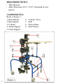
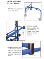
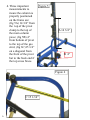
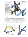
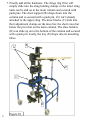
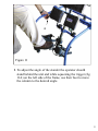
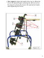
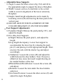
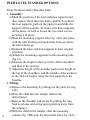
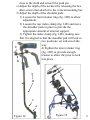
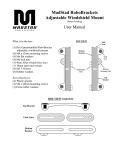
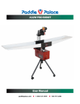
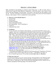
PEER LEVEL STANDERTM
PRONE ASSEMBLY
User’s Manual
1
TABLE OF CONTENTS
2
Preface
3
Precautions
3
Required Tools
4
Components
4
Assembly
5-9
Trouble Shooting
10
Fitting Instructions
10
Adjustment Overview
11
Adjustments
12-15
Options: Prone Neckrest and/or Shoulder Pads
16-17
Placing the Child in the Stander
18
Maintenance
19
PREFACE:
These pages provide information to professionals for the
set up and use of the Prone Assembly version of the Peer
Level Stander. The Mulholland Standing Systems are
designed to provide individuals requiring prone, vertical,
or supine standing, precise postural control at the upper
trunk, pelvis, knees and ankles. All standers adjust from
prone to vertical to offer therapists the opportunity to
provide graduated weight-bearing to promote more normal
tone distribution and stability, and selective extension of
the spine. Standers also stimulate head-righting, weightbearing on the forearms and mid-line hand use. Standing
provides an additional opportunity for peer socialization
and interaction, and upper extremity activities should be an
integral part of the standing program.
PRECAUTIONS:
Standing should always be prescribed by the child's
physician with recommendations for the duration,
frequency, and contraindications.The standing program
should be closely monitored by the child's therapist. USE
OF THE STANDER SHOULD BE UNDER DIRECT
ADULT SUPERVISION AT ALL TIMES.
3
REQUIRED TOOLS:
•
•
Tape Measure
Allen Wrenches (3/16”, 5/32”) (Included in tool
pouch)
COMPONENTS:
Refer to Figure 1.
1. Knee Blocks
2. Hip Support
3. Column
4. Trunk Support
5. Chest Support
6.
7.
8.
9.
Column Pivot
Strut
Frame Brace
Side Frames
5
4
3
6
2
1
7
8
4
Figure 1
9
PRONE ASSEMBLY
INSTRUCTIONS:
1. Attach the two side frames
to the frame brace.
2
2. With the two side
frames attached (they
may need to be
slightly loose), slide
the pivot bar into
position.
3. Tighten the TWO bolts
on the bottom of each
side, and make sure the
block is situated so the
pivot bar is above the
frame.
5
4. Three important
measurements to
insure the column is
properly positioned
on the frame are:
(fig 5A) 14 3/4” from
the top of the pivot
clamp to the top of
the main column
piece; (fig 5B) 4”
from bottom of pivot
to the top of the gas
strut; (fig 6C)15 1/4”
on a diagonal from
the front of the pivot
bar to the back end if
the top cross brace.
Figure 5
A 14 3/4”
B 4”
Figure 6
C 15 1/14”
6
5. Attach the upper
end of the gas
strut to the
receiver
mounting (fig
7A) on the main
column. Then
attach the lower
(and thinner) end
of the black gas
strut to the black
plate between the
cross bars (fig
7B). Tighten
these bolts well.
Figure 7
A
B
6. The tray mounting tubes (fig 8A) should be attached approximately 6” from the front edge of the crossbar
mounting block to the center of the tray bar mounting
block with the tray mounting tube pointing upwards and
mounted on the inside of the side frame (fig 9B).
Retighten the screws.
B
A
Figure 8
Figure 9
7
7. Finally add all the hardware. The slings (fig 10A) will
simply slide into the sling holding clamps or the intact sling
units can be slid on to the main column and secured with
push pins. The chest support (B) drops down into the
column and is secured with a push pin, if it isn’t already
attached to the upper sling. The knee blocks (C) slide into
their adjustment clamps on the knee bar, the short cross bar
below the pivot bar on the main column. The shoe holders
(D) can slide up on to the bottom of the column and secured
with a push pin. Lastly, the tray (E) drops into its mounting
tubes.
B
A
E
C
D
8
Figure 10
A
Figure 11
8. To adjust the angle of the stander the operator should
stand behind the unit and while squeezing the trigger (fig
11A) on the left side of the frame, use their foot to move
the column to the desired angle.
9
TROUBLE SHOOTING:
Careful alignment of the Peer Level Stander during
assembly is critical to the correct functioning of the
mechanical tilt mechanism. If the stander doesn’t tilt
correctly after assembly check the following list of
common problems.
The frame is not square: The side frames need to be
parallel to each other and the frame braces need to be
perpendicular to the side frames.
The knee block bar is not parallel to the frame braces.
The column is twisted. The push pin holes need to be in
line with the column pivot.
FITTING INSTRUCTIONS:
The following measurements are required prior to fitting
the Peer Level Stander:
10
1. Heel to iliac crest: This is the measurement to the top
of the hip support. ___
2. Groin to mid-scapula: This is the measurement to the
top of the trunk support. ___
3. Floor to mid-knee: This is the measurement to the
middle of the knee support. ___
4. Hip width: This is the measurement of the width of the
hip support. ___
5. Trunk width: This is the measurement of the width of
the trunk support. ___
6. Leg length discrepancy: The amount of distance that
the individual foot support must be lowered on the
longer side. ___
ADJUSTMENT OVERVIEW:
The separate and combined adjustments are critical to the
effectiveness of the Peer Level Stander. The therapist is
encouraged to try various adjustment combinations to find
the optimal position for weight-bearing, tonal balance and
head-righting. It is further recommended that an on-going
adjustment schedule be identified to meet the needs of
physical growth, decrease or increase in postural support,
and weight bearing activities.
•
•
•
•
•
Column Tilt (Pitch): Affects the child's orientation in
space, postural tone and distribution of weight.
Hip and Trunk Supports: Provide not only lateral, but
also anterior/posterior support. Although the hip
support should always be snug, the trunk support can be
graded to allow for lateral movement as the child
acquires increased trunk control.
Knee Supports: Knee blocks provide not only anterior
support, but can also change in angle to accommodate
flexion at the knees.
Foot Supports: The full Footplate was designed for a
level weight bearing surface. The 5-Way Adjustable Foot
Supports can accommodate anterior/posterior
adjustment, leg length discrepancies, plantarflexion/
dorsiflexion, and rotation
Tray Height: Tray height adjustment can provide an
upper extremity weight-bearing surface (to assist with
head control), and a surface for activity placement. A
pitch adjustable tray is available for an additional charge.
11
PEER LEVEL STANDER™ ADJUSTMENTS:
Note: The columns on these standers telescope up from the
foot support. This allows the child to stand as close to the
floor (peer level) as possible.
NEVER MAKE ANY OF THESE ADJUSTMENTS
WITH THE CHILD IN THE STANDER!
•
•
•
•
12
Foot Support: Initially, measure from the foot support
to the knee pad and lower or raise the foot supports to
the desired height (floor to mid-knee measurement) with
the push pin (fig 12A). Note: Fine tuning instructions for
the Foot Supports to follow.
Trunk Support: Removing both push pins (B & C) pull
the column up to the correct height for the chest support
and put trunk pin (B) in place. Place the chest support
(D) to approximately the level of the child's clavicles.
Note: This is not a chin rest.
Hip Support: Pull the hip support up to the desired
height (heel to iliac crest measurement) and replace the
pin (C).
Hip and Trunk Support Widths: Loosen the black
knobs (E) and slide the bars to the appropriate width
(you may need to loosen the straps). It is very
important to make sure that the outsides of the bars
are an equal distance from the mid-line of the
column. If they are not, the child may not be weight
bearing evenly. Tighten the knobs and re-velcro the
inside strap. This will be adjusted later as part of the
"fine tuning" while the child is in the stander. Complete
this adjustment for both the trunk and hip supports.
•
Tray support: Adjust the height of the tray by lifting the
tray to the desired height, loosening the allen screws on
the stops (F), placing the stops at the appropriate height,
and retightening the screws.
D
B
C
F
E
A
Figure 12
13
•
•
14
Adjustable Knee Supports
1) Angle: Loosen the allen screws (fig 13A) and tilt to
the appropriate angle to support the knees. Retighten.
2) Width: Loosen screws (A) and slide to the correct
width to assist in alignment of the lower extremity.
Retighten.
3) Height: Small height adjustments can be made by
loosening screws (B) and moving the knee pad on the
vertical post.
4) DO NOT ADJUST THE PLACEMENT OF THE
COLUMN BRACKET (F) ON THE STANDER!
Foot Support Adjustments:
1) Footplate Height: Release the push pin(fig 13C), and
adjust the height.
2) Five-Way Foot Supports:
a) Height: Release the push pin(C), and adjust the
height.
b) Leg length discrepancy: Lower foot support to
accommodate the lower leg by releasing the push
pin (C) and placing it at the appropriate height. Then
unscrew the side with the shorter leg and adjust
accordingly.
c) Abduction: Loosen the screws (D) and adjust the
width between the shoe holders. Note: Excessive
abduction may cause increased weight-bearing on
the medial borders of the feet.
d) Plantarflexion/Dorsiflexion: Loosen the screws (D)
and adjust.
e) Rotation: Loosen the nuts under the shoe holders
and pivot.
f) Inversion/Eversion: Loosen the allen screws (E) and
adjust the angle. Retighten.
3) AFTER ADJUSTING FOOT SUPPORTS,
RECHECK TO MAKE SURE THAT ALL OF
THE SCREWS HAVE BEEN TIGHTENED. An
appropriate fitting is that which supports the child
securely and promotes symmetrical weight-bearing.
Figure 13
15
PEER LEVEL STANDER OPTIONS:
16
Prone Neckrest and/or Shoulder Pads:
1. Assembly:
a) Mark the position of the foot and knee supports and
then remove them from the main column. To remove
the foot supports, pull out the push pin and slide the
support off the column. To remove the knee supports,
do the same, as well as loosen the two allen screws
securing it in place.
b) Slide the mounting support tube (fig. 14A) into place,
with the tube sticking out backwards between where
the knee blocks go.
c) Reattach the knee and foot supports to their original
positions.
d) Attach the remaining segments to the mounting tube
(fig 15).
e) Measure the height to the top of the child’s shoulders
and then to the mid ear.
f) Adjust the height of the shoulder pads to the height of
the top of the shoulders, and the middle of the neckrest
to the mid-ear height, using the foot supports as the
baseline.
2. Fitting:
a) Remove the mounting by pulling out the push pin (fig.
14C).
b) Place the child into the stander (follow the
instructions).
c) Release the shoulder pad pivots by pulling the ring
back to release and swing open (pointing away from
the column.)
d) With the child in the stander, slide the mounting
column (fig. 14B) onto the horizontal tube (fig. 14A)
close to the child and reinsert the push pin.
e) Adjust the depth of the neckrest by releasing the two
allen screws that attach it to the vertical mounting bar.
f) Adjust the depth of the shoulder pads:
1) Loosen the front retainer ring (fig. 14D) to allow
adjustment.
2) Loosen the rear index clamp (fig. 14E) and move
the shoulder pads in place to provide the
appropriate amount of anterior support.
3) Tighten the index clamp (fig. 14E), making sure
that it is aligned so that the shoulder pad will lock in
two positions: set and out-of-theway.
E
4) Tighten the inner retainer ring
(fig. 14D) to provide enough
tension to allow the pivot to lock
into place.
D
B
C
A
Figure 14
Figure 15
17
PLACING THE CHILD IN THE STANDER:
1. Always lock all four casters before putting the child in
the stander. This is done by stepping on the lock lever on
each castor.
2. The child's therapist should identify whether or not one
or two people should be required for the standing
transfer.
3. Placing the child's feet on the foot supports, slowly lift
him/her into the stander, fastening the hip straps first,
then the trunk straps. After checking for proper
alignment and weight bearing, fasten the buckle straps
on the hip and trunk supports, the foot supports, and the
knee straps.
4. The child should be directly supervised at all times.
5. Provide a table or socialization activity while the child is
standing.
6. Observe the child closely for signs of fatigue, distress, or
discomfort, and remove the child within the prescribed
period.
18
MAINTENANCE:
1. Keep the stander clean. The metal and plastic parts can
be washed with a mild concentration of dish soap (the
same as is used on your dishes). Rinse with water and
dry. Wipe down all of the upholstered parts with a damp
cloth.
2. Check weekly for frayed straps and Velcro. For the
child's safety, discontinue use of the stander until worn
Velcro and straps are replaced.
3. Periodically check for loose screws and tighten them as
needed.
19