1
A Software Tool to Enable Setting up Network
and System Configurations
Jennifer Poole
Computer Science with Mathematics
2006/2007
The candidate confirms that the work submitted is their own and the appropriate credit has been given
where reference has been made to the work of others.
I understand that failure to attribute material which is obtained from another source may be considered
as plagiarism.
(Signature of student)
Summary
The purpose of this project is to design and produce a software tool for use by BAE Systems, a widely
known defence company. The tool is to be used by the SAINTT team (Systems Analysis and Integration
Technology).
The team need to be able to set their computers up to imitate already existing systems that are used
on ships, created by BAE Systems. The reason for this is that the SAINTT equipment is used to test
how different systems integrate and communicate with each other, as well as testing certain parts of
each system themselves. Each system that the team needs to be able to imitate will be referred to as
‘interfaces’ from now on.
The team currently use a configuration file which states the various details that must be set up. This
configuration file is run upon start up and sets up any ports or IP addresses specified. At the moment,
the team have to manually alter this configuration file in order to get the correct details set up. When
carrying out my placement with the team, I experienced first hand how irritating and tedious this could
be and when I mentioned I needed a project for my final year, it was agreed that a tool that could be
used to set the computers up would be very beneficial to the team.
During the project, it is important to receive constant feedback from the Technical Authority that the
system I was producing was as they required. It is a great benefit to me that I have previously worked
on the team and know the level of the technical skills of the members of the team.
i
Acknowledgements
First of all I would like to thank Brandon Bennet, my supervisor, for being patient with me and listening
to me moaning and complaining at times. I would also like to thank him for all his help and input to my
project and keeping me going when I was down!
I would also like to thank the staff on the SAINTT team at BAE Systems, in particulat the Technical
Authoroty Manager. I am very grateful to have been given the project from the company and even more
grateful for the Technical Authority’s help with all of my coding problems! I hope the final product is
as they expected and will be of use to them.
My housemates for understanding how stressed I have been and not holding me to any arguments or
general stroppyness throughout the period. They all helped in reassuring me that I would get the project
finished on time and to my best possible standards.
My mum for her help proof reading this report and pointing out spelling mistakes I had failed to notice.
Most of all, I’d like to thank Sarah, the project coordinator.
ii
Contents
1
2
Chapter 1 - Introduction
1
1.1
Company . . . . . . . . . . . . . . . . . . . . . . . . . . . . . . . . . . . . . . . . .
1
1.2
Problem . . . . . . . . . . . . . . . . . . . . . . . . . . . . . . . . . . . . . . . . . .
2
1.3
Solution . . . . . . . . . . . . . . . . . . . . . . . . . . . . . . . . . . . . . . . . . .
2
1.4
Aim . . . . . . . . . . . . . . . . . . . . . . . . . . . . . . . . . . . . . . . . . . . .
3
1.5
Objectives . . . . . . . . . . . . . . . . . . . . . . . . . . . . . . . . . . . . . . . . .
3
1.6
Requirements . . . . . . . . . . . . . . . . . . . . . . . . . . . . . . . . . . . . . . .
4
1.7
Extended Req . . . . . . . . . . . . . . . . . . . . . . . . . . . . . . . . . . . . . . .
5
1.8
Deliverables . . . . . . . . . . . . . . . . . . . . . . . . . . . . . . . . . . . . . . . .
5
1.9
Relevance to degree . . . . . . . . . . . . . . . . . . . . . . . . . . . . . . . . . . . .
5
1.10 Project Schedule . . . . . . . . . . . . . . . . . . . . . . . . . . . . . . . . . . . . .
6
Background Research
7
2.1
Introduction . . . . . . . . . . . . . . . . . . . . . . . . . . . . . . . . . . . . . . . .
7
2.2
The Current System Used . . . . . . . . . . . . . . . . . . . . . . . . . . . . . . . . .
7
2.3
Primary Research . . . . . . . . . . . . . . . . . . . . . . . . . . . . . . . . . . . . .
8
2.4
Secondary Research . . . . . . . . . . . . . . . . . . . . . . . . . . . . . . . . . . . .
8
2.4.1
IP Addresses and Formats . . . . . . . . . . . . . . . . . . . . . . . . . . . .
8
2.4.1.1
Research . . . . . . . . . . . . . . . . . . . . . . . . . . . . . . . .
8
2.4.1.2
In relation to the Problem . . . . . . . . . . . . . . . . . . . . . . .
9
Document Markup Languages . . . . . . . . . . . . . . . . . . . . . . . . . .
9
2.4.2
2.4.2.1
HTML Research . . . . . . . . . . . . . . . . . . . . . . . . . . . .
10
2.4.2.2
XML Research . . . . . . . . . . . . . . . . . . . . . . . . . . . . .
10
iii
2.4.2.3
In relation to the problem . . . . . . . . . . . . . . . . . . . . . . .
10
Computer Programming Languages . . . . . . . . . . . . . . . . . . . . . . .
12
2.4.3.1
Java Research . . . . . . . . . . . . . . . . . . . . . . . . . . . . .
12
2.4.3.2
C++ Research . . . . . . . . . . . . . . . . . . . . . . . . . . . . .
12
2.4.3.3
In relation to the Problem . . . . . . . . . . . . . . . . . . . . . . .
12
GUI Design and programming . . . . . . . . . . . . . . . . . . . . . . . . . .
12
2.4.4.1
Design Research . . . . . . . . . . . . . . . . . . . . . . . . . . . .
14
2.4.4.2
Programming Research . . . . . . . . . . . . . . . . . . . . . . . .
14
2.4.4.3
With relation to the problem . . . . . . . . . . . . . . . . . . . . . .
15
Schemas and Grammas . . . . . . . . . . . . . . . . . . . . . . . . . . . . . .
15
2.4.5.1
Research . . . . . . . . . . . . . . . . . . . . . . . . . . . . . . . .
15
2.4.5.2
In relation to the problem . . . . . . . . . . . . . . . . . . . . . . .
17
Previous Solutions . . . . . . . . . . . . . . . . . . . . . . . . . . . . . . . . . . . .
17
2.5.1
17
2.4.3
2.4.4
2.4.5
2.5
3
4
PuTTy . . . . . . . . . . . . . . . . . . . . . . . . . . . . . . . . . . . . . . .
Methodology
18
3.1
Overview . . . . . . . . . . . . . . . . . . . . . . . . . . . . . . . . . . . . . . . . .
18
3.2
Design . . . . . . . . . . . . . . . . . . . . . . . . . . . . . . . . . . . . . . . . . . .
18
3.3
Write up . . . . . . . . . . . . . . . . . . . . . . . . . . . . . . . . . . . . . . . . . .
19
3.4
Testing and Evaluating . . . . . . . . . . . . . . . . . . . . . . . . . . . . . . . . . .
20
3.5
Problems . . . . . . . . . . . . . . . . . . . . . . . . . . . . . . . . . . . . . . . . .
20
3.5.1
Re Designing . . . . . . . . . . . . . . . . . . . . . . . . . . . . . . . . . . .
20
3.5.2
Enhancing . . . . . . . . . . . . . . . . . . . . . . . . . . . . . . . . . . . .
21
3.5.2.1
21
User Guide . . . . . . . . . . . . . . . . . . . . . . . . . . . . . . .
Design
22
4.1
Configuration Files . . . . . . . . . . . . . . . . . . . . . . . . . . . . . . . . . . . .
22
4.2
Schema . . . . . . . . . . . . . . . . . . . . . . . . . . . . . . . . . . . . . . . . . .
23
4.2.1
Initial Design . . . . . . . . . . . . . . . . . . . . . . . . . . . . . . . . . . .
23
GUI . . . . . . . . . . . . . . . . . . . . . . . . . . . . . . . . . . . . . . . . . . . .
26
4.3.1
Navigation . . . . . . . . . . . . . . . . . . . . . . . . . . . . . . . . . . . .
26
4.3.2
Graphics . . . . . . . . . . . . . . . . . . . . . . . . . . . . . . . . . . . . .
27
4.3
iv
5
6
7
4.3.3
Initial Design . . . . . . . . . . . . . . . . . . . . . . . . . . . . . . . . . . .
28
4.3.4
Comments . . . . . . . . . . . . . . . . . . . . . . . . . . . . . . . . . . . .
28
4.3.5
Final Design . . . . . . . . . . . . . . . . . . . . . . . . . . . . . . . . . . .
28
Implementation
29
5.1
GUI . . . . . . . . . . . . . . . . . . . . . . . . . . . . . . . . . . . . . . . . . . . .
29
5.1.1
Problem I . . . . . . . . . . . . . . . . . . . . . . . . . . . . . . . . . . . . .
29
5.1.2
Solution I . . . . . . . . . . . . . . . . . . . . . . . . . . . . . . . . . . . . .
30
5.1.3
Problem II . . . . . . . . . . . . . . . . . . . . . . . . . . . . . . . . . . . .
31
5.1.4
Solution II . . . . . . . . . . . . . . . . . . . . . . . . . . . . . . . . . . . .
31
5.1.5
Final GUI . . . . . . . . . . . . . . . . . . . . . . . . . . . . . . . . . . . . .
32
5.2
File I/O . . . . . . . . . . . . . . . . . . . . . . . . . . . . . . . . . . . . . . . . . .
32
5.3
Validation . . . . . . . . . . . . . . . . . . . . . . . . . . . . . . . . . . . . . . . . .
33
5.3.1
Node Id . . . . . . . . . . . . . . . . . . . . . . . . . . . . . . . . . . . . . .
33
5.3.2
IP Addresses . . . . . . . . . . . . . . . . . . . . . . . . . . . . . . . . . . .
34
5.3.3
Network Card . . . . . . . . . . . . . . . . . . . . . . . . . . . . . . . . . . .
34
5.3.4
Port numbers . . . . . . . . . . . . . . . . . . . . . . . . . . . . . . . . . . .
35
5.4
Global Data . . . . . . . . . . . . . . . . . . . . . . . . . . . . . . . . . . . . . . . .
36
5.5
IP Aliasing . . . . . . . . . . . . . . . . . . . . . . . . . . . . . . . . . . . . . . . .
36
Testing
38
6.1
Phase I . . . . . . . . . . . . . . . . . . . . . . . . . . . . . . . . . . . . . . . . . . .
38
6.2
Problems and Alterations . . . . . . . . . . . . . . . . . . . . . . . . . . . . . . . . .
38
6.3
Phase II . . . . . . . . . . . . . . . . . . . . . . . . . . . . . . . . . . . . . . . . . .
39
6.4
Problems and Alterations II . . . . . . . . . . . . . . . . . . . . . . . . . . . . . . . .
39
6.5
Phase III . . . . . . . . . . . . . . . . . . . . . . . . . . . . . . . . . . . . . . . . . .
39
6.6
Problems and Alterations III . . . . . . . . . . . . . . . . . . . . . . . . . . . . . . .
40
6.7
Phase IV - Final Testing . . . . . . . . . . . . . . . . . . . . . . . . . . . . . . . . .
40
6.8
Problems and Alterations IV . . . . . . . . . . . . . . . . . . . . . . . . . . . . . . .
40
Evaluation
41
7.1
41
Evaluation Criteria . . . . . . . . . . . . . . . . . . . . . . . . . . . . . . . . . . . .
v
7.1.1
User Requirements . . . . . . . . . . . . . . . . . . . . . . . . . . . . . . . .
41
7.1.2
Aim & Objectives . . . . . . . . . . . . . . . . . . . . . . . . . . . . . . . .
43
7.1.3
Minimum Requirements . . . . . . . . . . . . . . . . . . . . . . . . . . . . .
43
7.1.4
Additional Functionality . . . . . . . . . . . . . . . . . . . . . . . . . . . . .
45
7.1.5
Methodology . . . . . . . . . . . . . . . . . . . . . . . . . . . . . . . . . . .
45
7.1.5.1
Design . . . . . . . . . . . . . . . . . . . . . . . . . . . . . . . . .
45
7.1.5.2
Write Up . . . . . . . . . . . . . . . . . . . . . . . . . . . . . . . .
46
7.1.5.3
Testing and Evaluating . . . . . . . . . . . . . . . . . . . . . . . .
46
7.1.5.4
Problems . . . . . . . . . . . . . . . . . . . . . . . . . . . . . . . .
46
7.1.6
Usability . . . . . . . . . . . . . . . . . . . . . . . . . . . . . . . . . . . . .
47
7.1.7
Additional Functionality . . . . . . . . . . . . . . . . . . . . . . . . . . . . .
48
7.1.8
Testing . . . . . . . . . . . . . . . . . . . . . . . . . . . . . . . . . . . . . .
49
7.1.9
Company Evaluation . . . . . . . . . . . . . . . . . . . . . . . . . . . . . . .
49
7.1.10 Improvements . . . . . . . . . . . . . . . . . . . . . . . . . . . . . . . . . . .
49
7.1.11 Comparison of Other Products . . . . . . . . . . . . . . . . . . . . . . . . . .
50
Appendix A: User Reflection
51
Appendix B: Tasking Memo
53
Appendix C: Gantt Charts
57
Appendix D: Past Configuration File
60
Appendix E: Tutorial Notes
61
Appendix F: New Configuration File
63
Appendix G: Schema Design
68
Appendix H: GUI Design
76
Appendix I: Final GUI Design
81
Appendix J: Glade Windows
84
vi
Appendix K: GUI Problems
87
Appendix L: Screen Shots of Program
94
Appendix M: Phase I Test Schedule
102
Appendix N: Phase II Test Schedule
105
Appendix O: Phase III Test Schedule
109
Appendix P: GUI Feedback
116
Appendix Q: User Guide
118
Appendix R: GUI Design Research
130
Appendix S: Creating a DTD
141
Appendix S: Company Evaluation
143
Appendix U: Details of Additional Functionality
145
Bibliography
147
vii
Chapter 1
Chapter 1 - Introduction
1.1
The Company
BAE Systems is the largest European defence company that assists in the development, delivery and
support of advanced defence systems. They produce software for systems in the air, on land, at sea as
well as in space. The company also design, manufacture and support military aircraft, ships, submarines,
radar, guided weapon systems and much more. They provide major operations accross five continents
and to customers in over 130 coutries. They have a subsidary in the US which is based in Rockville,
Maryland. This company is responsible for developing the transatlantic business, relationships with the
US Government and managing its US based Operating Groups which collectively employ over 45,000
employees in the US, UK, Sweden, Isreael and South Africa.
More specifically, the SAINTT (Systems Analysis and Integration Technology) team are a small team
within BAE Systems who provide a set of programs to enable the testing of existing systems and aid the
production and development of new systems. SAINTT is used to create and run ‘scenarios’ to imitate
various real life activities such as firing missiles and detecting foreign vehicles. In order to run these
scenarios and test that the existing systems are behaving correctly, the computer must be set up to imitate
that system. This is where this project comes into play.
1
1.2
The Problem
The problem the SAINTT team have is that there is no software to enable the setting up of the computers.
This means that currently, when members of other teams wish to use the SAINTT system, a member
of the SAINTT team must be called to set the machine up for them. As can be imagined, this is very
tedious and time consuming. The main aim of the SAINTT equipment is to imitate other existing
systems created by the company. This means that it has to behave exactly like the real system would
without the physical actions. For example, if it were imitating a weapons system, it would produce the
exact same signals and outputs as the weapons system, but when the ‘fire’ signal is emmited, it won’t
actually fire a weapon. But in order to assure accurate testing, everything the weapons system does
within the computer needs to be replicated by the SAINTT machine. It was decided that some kind of
tool was needed so that all members of BAE Systems could set their computer up to imitate any other
system when needed, without the aid of a SAINTT team member.
This involves enabling specific numbers of IP Addresses and Ports to be set up along with various other
attributes specific to each interface (system). The tool must produce a configuration file when the user
exits which will then be run on reboot to actually set up the physical IP Addresses and Ports specified.
It is also required that the tool automatically displays the current configuration to the user on starting
the tool and that there is an option to save the configuration to a specified name for future use. This
will prevent users having to repeat the set up for long/complex configurations or just commonly used
configurations. It will also help when the team have to perform tests to prospective clients so that they
can simply load previously saved configurations rather than spend time setting the machines up at the
time.
BAE Systems provided a ‘Tasking Memo’ outlining the problem and certain guides towards the solution.
This document can be seen in Appendix B.
1.3
Solving the Problem
The SAINTT team agree that the current procedure for setting up the required details of the machines
can be greatly improved and efficiency will be increased through the use of a software tool. The above
problem will be solved by producing such a tool with a user friendly graphical interface that will be
simple to use. The loading and saving of configurations will greatly improve the usability of the SAINTT
system and give the system a better overall appearance to prospective clients. It will benefit the whole
2
company since it will enable any team member to set up their own machine and will prevent mistakes
being made which could lead to inaccurate test results. When producing the software to solve this
problem, the current structure of configuration files will be taken into account and the views of the
current SAINTT team will be used to assist the production of the tool. It should be noted that for each
interface, more than one set of IP Addresses can be set up. In order to distinguish between these sets of
IP Addresses, they are allocated a ‘node Id’. Each set of IP Addresses and node Id on each interface will
be refered to as a ‘node’ from now on. Since the company run on ‘secret’ networks that are not allowed
access to the internet, a web-based tool would not be of benefit.
1.4
Aim
The aim of this project is to produce a stand alone tool that can be used to configure computers to imitate
existing systems at BAE Systems. The tool should allow the user to set up IP Addresses and Sockets
for the various interfaces supported by the SAINTT team. The interfaces refered to here are interfaces
(or systems) created by BAE Systems that are specific to the company. The tool will be used to set
up computers to imitate one of fifteen different interfaces (although the scope of this project is to get
the tool to work for five different interfaces). Each interface implemented has a different specification
and various details must be set up. It has been asked that the tool should be able to load previously
saved configurations and save the current configuration for future use. This feature is required so that
common configurations do not need to be set up again and again since some configurations will have
many interfaces set up at one time.
1.5
Objectives
To enable the aim to be completely satisfied, the following objectives must be met:
• Design and produce a GUI for the tool
• Enable the tool to read in previously saved configurations
• Enable the tool to write out configurations that are to be saved
• Ensure validation of all information entered by the user
• Design and produce a schema to ensure validation on input and output configuration files
3
• Fully test the tool before delivering to BAE Systems for feedback
• Take any points brought up by the company and amend the tool as applicable
1.6
Minimum Requirements
In order to achieve the aims of this project, the following minimum requirements must be met:
1. View and Edit configuration Files.
• The tool should be able to view the current configuration and allow the user to edit any
details as they may wish. The user should be able to chose whether they want to save over
the original configuration or save it to a new name.
2. Manage and Load previously saved conifurations.
• The tool should allow the user to open/load previously saved configuration files and then
update the file that is used to produce the physical IP Addresses and Ports so that the current
configuration is set up on reboot.
3. Enforce correct syntax of input and output configuration files
• The tool should automatically check that the files being read in and written out comply to
a previously written schema. If the input file has incorrect syntax, the tool should alert the
user of the error. If this error is produced on start up, default values should be used. If this
error occurs on loading another configuration, the current configuration should remain..
4. Validate user input
• The tool should check every field that the user inputs and validate it against a previously
agreed set of values for the specified field. If the user enters an invalid piece of information,
the tool should alert the user and allow them to re enter the information. Invalid information
will never be saved to a configuration file.
Any other features added to the software will be an aditional benefit to the tool, not specifically required
by BAE Systems but of benefit to them.
4
1.7
Possible extension of minimum requirements
If any of the following are met, the overall system will be of greater use to the company:
1. Function to allow easy addition of new interfaces
• An additional function could be added to the tool to allow a SAINTT team user to add new
interfaces to the tool. This function must only be allowed to be used by a SAINTT team
member and so should be password protected. After adding new interfaces to the tool, the
team member will have to deliver the new tool to those who may need it. The additonal
feature would produce the required additional menu items and GUI screens and produce the
code for the correct configuring of the interface. This feature would be very beneficial to the
team but would also be quite complex. The main reason being that it would be very difficult
to devise a generic form of interface specification that would be appropriate to any possible
interface.
2. Manual
• If there is time, a manual should be provided to the team so that they can forward it to any
member of the company who currently use the SAINTT system. It could also be beneficial to
the SAINTT team members themselves in case they are ever called out to support a problem
with the new tool
1.8
Deliverables
There will be one deliverable for this project, possibly two if extended requirements are carried out. The
main deliverable will be the software tool itself which should be delivered on CD. The possible additional deliverable would be a user manual, which should be in website format for use on the company’s
intranet.
1.9
Relevance to degree
This project will require many skills learnt thoughout the past four years. The main skills required
are programming (SE10, SE20, SE24 and experience from work placement), knowledge management
5
(DB32) and human computer interaction (GI11). It is clear that many other skills will also be required
which will be learnt along the way.
1.10
Project Schedule
In project management, it is very important to have a schedule to follow to ensure the project is completed correctly and on time. There are many ways of producing a schedule, Gantt Charts being a widely
known and used way. This way of scheduling enables you to keep track of your plan as well as your
actual work load, so that you can make any adaptations needed if it becomes clear you are widely behind schedule. An initial Gantt Chart was created for this project but along the way it became clear that
some alterations were needed. Certain sections were no longer needed and additional sections had to be
added. All versions of the Gantt Chart can be located in Appendix C.
6
Chapter 2
Background Research
2.1
Introduction
This chapter will look into the current ‘system’ used at BAE Systems. It will also explore many different
aspects required to create the new system, looking at advantages and disadvantages where appropriate
and explaining how each aspect can be used in the new system.
2.2
The Current System Used
Currently BAE Systems do not use a specific computerised system to set up their computers. Instead,
they use a configuration file which is edited when new configurations are required. The file contains all
the information required by the computer so that, on start up, the correct IP Addresses and Ports are set
up. A sample configuration file currently in use can be seen in Appendix D.
It is quite clear that this approach is very inefficient and quite a ‘hacky’ way to set up the computers.
The current system means that it is quite easy, and possible, to incorrectly set up the computer and it
also means that setting up is very tedious. The new system will need to take into account the current
values stored in the configuration files and use the same approach to set up the actual IP Addresses and
Ports (ie on start up).
7
2.3
Primary Research
Since I carried out a years placement at BAE Systems on the SAINTT team, I have first hand experience
of how the current system works and how the configuration files must be altered in order to set up
different interfaces (systems). I will take my years experience into account when producing the solution
and I will ensure constant feedback from the current team members throught the production of the
solution.
2.4
Secondary Research
In order to produce an accurate solution, I first need to do some research
2.4.1
IP Addresses and Formats
The system produced to solve the problem will need to validate information entered by the user to set
up configurations for the computers. One of the pieces of information needed from the user will be an
IP Address. The following section explores the format of IP Addresses to gain the required knowledge
to validate the user input.
2.4.1.1
Research
In researching IP Addresses and their formats, it was realised that there are more than one type of IP
Address. In fact there are many different classes of address that can be used for different things.
[1] explains the basics of the format of an IP Address, sumarised as follows:
• An IP Address must consist of four numbers
• Each of these numbers must be between 0 and 255
• No IP Address can consist totally of 0s or 255s
• Each number is seperated with a ‘.’
For example, 123.45.67.89
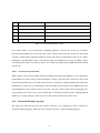
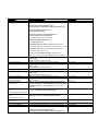
When it came to looking into the various classes of IP Address, it became apparent that there are five
different classes in total; Class A, Class B, Class C, Class D and Class E. [2, 3] explain these classes in
8
Class
Use
Restrictions
A
Assigning addresses to clients
The first term in the address must be between 0 and 126
B
Assigning addresses to clients
The first term in the address must be between 128 and 191
C
Assigning addresses to clients
The first term in the address must be between 192 and 223
D
Reserved for multicast addressing
The first term in the address must be between 224 and 247
E
Reserved for future development
The first term in the address must be between 248 and 255
Table 2.1: Different IP Address Classes
more detail. Table 2.1 was constucted by combining summaries of both books. It was also noted that
the networking number 127 is reserved for the ‘local loopback’ which is used for trouble shooting. Each
class has a subnet mask assignment which follows the same format as an IP Address but is used to define
which parts of the IP Address refer to the network address and which refer to the node address. There
are default subnet masks associated to classes A–C which are 255.0.0, 255.255.0.0 and 255.255.255.0
respectively.
2.4.1.2
In relation to the Problem
With regards to the problem in hand and after speaking with the Product Manager, it was agreed that
the IP Addresses in the system produced will simply comply to the basic rules stated above along with
the rule that the third term of the address must be the node Id (this is a unique number that enables the
identification of each node on each interface). Since the final system will be used by BAE Systems, the
actual IP Addresses that will be used are secret and so that part of the system will need altering by the
company themselves. Due to this, it was decided that no extra time should be put into validating the IP
Addresses to comply with any of the four classes and a simple validation should be used.
2.4.2
Document Markup Languages
The input and output files used for the system to load and save configurations will be written in a
document markup language. This next section explores the most common markup languages.
9
2.4.2.1
HTML Research
When looking into which markup language to use for the input and output files, [4] proved to be very
useful. After reading over what [4] had to say about HTML, it became clear very quickly that there
were more disadvantages to the markup language than advantages. For example, it was learnt that not
all computer programming languages are able to read in and write out HTML, making it quite obvious
that this markup isn’t best suited for the input and output of files in the system being produced. It was
also learnt that HTML is hard to read for a human due to the tags being nested and overlapped and, for
the same reason, HTML can be complex to write since the writer needs to know all the tags and what
they all mean. The final point that helped in a decision being made was that HTML is hard to debug the omission of a simple tag can takes ages to resolve.
2.4.2.2
XML Research
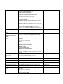
XML is another markup language that was based on HTML. [5] discusses the advantages and disadvantages of using XML and goes into detail on what XML is. As a summary, we learn that XML is a
metamarkup language that is used for text documents. A metamarkup language is one that does not
have fixed tags and elements that have to be used - the user can specify the names of both. The data
entered is written as a string and is surrounded in tags, a bit like HTML.
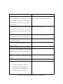
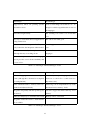
Table 2.2 summarises the advantages and disadvantages of using XML, obtained from [5, 6]: As can be
seen, there are a lot more advantages than disadvantages.
When it comes to parsing XML using most languages, there are two different API’s that can be used;
SAX and DOM. There is also data binding which is used with regards to Java.
2.4.2.3
In relation to the problem
After taking into account the above findings, it is obvious that XML should be used in relation to the
problem. Since the system is going to need to read in and write out files as well as validate information,
XML seems to be the best option as it can do this all in one. Since it has not been decided what
programming language is going to be used, it is probably best to look into using DOM or SAX APIs
when parsing XML into the program.
10
Advantages
Disadvantages
Metamarkup language. This allows the de-
It uses basic parsing requirements which
velopers and writers to define their own ele-
doesn’t support a wide range of data types
ments as they need them. It means that descriptive names can be used for tags which is
good practice.
It provides a grammar for the document. This
XML is not very concise
specifies where tags are allowed to be placed,
what they must look like, what names are legal . . .
You can use a parser that is able to read any
Parsing can be hard to grasp
document in most programming languages
The language is well structured and can be
There are some bad parsers around
easily read by humans
It is clear to the reader what data belongs to
what information
Validation can be carried out using a schema
It provides a good format for text documents
which is useful for reading in and writing out
files
XML is easy to debug - a basic text editor can
be used
It is language and platform independent
[5] says,
If a Perl program and a Java program need to communicate, generating and processing XML can
be simpler than the alternatives.
Table 2.2: Advantages and Disadvantages of using XML
11
2.4.3
Computer Programming Languages
When deciding what programming language to use for the product that is to be created to solve the
problem, it seemed a good idea to look into those languages that a basic knowledge of is already known.
So, both Java and C++ were researched.
2.4.3.1
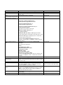
Java Research
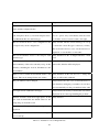
Table 2.3 shows the advantages and disadvantages of using Java which has been collated by summarising
information obtained from [7, 8]
2.4.3.2
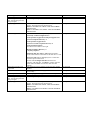
C++ Research
[8] was also used to look into the advantages and disadvantages of C++ as shown in Table 2.4 [8] also
states:
C++ is an object-oriented language, and when you program well in C++, you are thinking about objects and their responsibilities. Tiny programs in C++ look very much like
programs in C, but larger C++ programs are completely different.
2.4.3.3
In relation to the Problem
Looking at the advantages and disadvantages of C++ and Java above, along with the fact that the most
recent language I have used is C++, it has been concluded that C++ should be used to code the system
to solve the problem. It appears C++ has more resources and help with regards to parsing XML and
I have had previous experience parsing with this language. When discussing this conclusion with the
Product Manager, it was agreed that this was a good choice, especially since the Software Engineers at
BAE Systems only know C++ and not Java and they will be required to keep the system up to date in
the future.
2.4.4
GUI Design and programming
Since one of the important factors of the solution is that the system is easy to use and must have a pleasant graphical interface, it is important to look into how to design such a system and, more importantly,
how to program it.
12
Advantages
Disadvantages
Supported by almost all operating systems
Some esoteric things can be hard to do - al-
and web browsers
though it could be argued that this is true for
all languages.
Java allows high security
The resulting code seems to be slower than
C++
It is easy to create network based applications
The editors aren’t that good
using client/server
Classes are stored in seperate files.They are
The debuggers aren’t as well written or as ro-
only loaded into the interpreter when needed
bust
Java can automatically clean up lost memory
Java is still new - it isn’t as mature as other
although this may slow things down
languages
It is much simpler to write than most language
and it provides nearly all the flexibility and
power of C++
Table 2.3: Advantages and Disadvantages of Java
Advantages
Disadvantages
The resulting program can be run on all plat-
A relatively complex language (I already
forms (although the code must be recompiled
know how to code in C+ + so this doesn’t re-
on each platform)
ally relate to me)
It has advanced features - memory can be ex-
Subtle bugs can be implemented very easily
amined and adjusted directly
which can lead to memory ‘leaks’
Programs run quickly and take up little space
It doesn’t support automatic clean up of lost
in memory
memory
There are many ways to obtain the same result
Memory can be overwritten
Programs created are easier to obtain and are
more reliable
Table 2.4: Advantages and Disadvantages of C++
13
2.4.4.1
Design Research
When it comes to designing a GUI, there is a lot to take into consideration. A summary of things to
remember and things to avoid can be seen in Appendix R. When creating the GUI for my program, I will
ensure I adhere to as many of these rules as possible and try to maximise the usability of the GUI. Some
key points I will remember are to ensure the layout of all windows is the same and, if not identical, then
very similar, not to over complicate the program by trying to help the user, use icons where appropriate
but don’t confuse the user by using icons relating to another function. When designing the GUI, it is
important to think about the different types of people who are going to be using the program; their age,
their ability, their competance etc. It is important to design a GUI that appeals to all the prospective
users. In order to ensure the GUI is appropriate, designs will be discussed with the Technical Authority
Manager of SAINTT and amendments will be made where necessary.
2.4.4.2
Programming Research
After researching programming a GUI, it appears that there are a few different ways that it can be done.
Firstly, there is a program on linux that can be used to create the GUI. This program is called Glade and
works by creating an XML file which contains all the details of the GUI. In this program, you can create
every window and dialog needed and using the properties menu you are able to name every ‘widget’ for
use in the code later. It is also possible to add all signal handlers to buttons, menu items etc using Glade
and name them as required for later use. To use the GUI created with this program, the Glade library
must be linked into the makefile when creating the program from the code. Within the code, a call must
be made to open the XML file created by Glade followed by a call to automatically connect the signal
handlers to the ‘widgets’. However, as far as can be seen, Glade is only compatible with C++, not Java.
Since earlier on in my research I decided it would be best to use C++ over Java, Glade is an option I
could use.
Another option is to use the GTK library and create the GUI within my code by hand. This could be
quite time consuming but is another option. In this case, all signals would be connected to widgets when
needed. If this option was to be used, it would be a good idea to have a seperate class that creates a
basic window and one that creates a basic dialog. These classes could then be used everytime a new
window/dialog was to be created and by providing certain methods, the required changes could be made
when necessary.
14
Finally, there is a library called gtkmm that could be used. This library provides a basic generation of
every widget provided by GTK and would be used in my code by inheritance. This option seems to be a
better way of creating the GUI than the hard coding using GTK, since a lot of the code is already done
for you within the library. It would be a lot quicker and simpler than coding from scratch.
2.4.4.3
With relation to the problem
Many of the design aspects mentioned above are for larger, more complex systems than the one being
produced. Those that are relevant to this solution will be taken into account when producing an initial
GUI design. More importantly, the design will be presented to the Technical Authority Manager of
SAINTT and the feedback will be used to create the final design before any programming is carried out.
It appears that Glade works well with C++ and provides a simple and easy way of producing the GUI.
This will be the approach used for the solution. [11, 12] will be used to help with using Glade.
2.4.5
Schemas and Grammas
Since I am using XML for my configuration files, it would be a good idea to look into using a schema
or grammar with the file to ensure correctness of the file. This would ensure that all files being read in
are of the correct format and contain all the right tags in the correct order for the program.
2.4.5.1
Research
After reading a few books on XML Schemas, it appears that there is more than one type of schema to
chose from. The following information was obtained by sumarising the content from [13] and [14].
DTD’s
Standing for ‘Document Type Definitions’, DTDs provide a source of tools for defining the element
and attribute structures allowed in a document. It can also be used as a way to provide default values
for attributes and for defining metadata information. They are widely supported and used although the
capabilities provided have quickly been outgrown.
Some disadvantages of DTD’s are:
• They don’t support namespaces
• They have weak data typing
• They are easy to learn how to use but the readability isn’t that great
15
• You can’t define a root element
This last point means that it could be possible for a file to be ‘valid’ even if it is missing the first 4
elements, say, but has the rest of the elements correct.
On the other hand, DTD’s have the widest support in literature and software and have 10 data types
available.
A DTD:
Declares a set of allowed elements - no other element name can be used other than those specified in
this set.
Defines a ‘content model’ for each element - the content model is a pattern that specifies which elements
or data can go inside an element. It also specifies the order the elements/data must be in, how many of
each element/data can be entered and whether the element/data is required or optional.
Declares a set of allowed attributes for each element - the attribute declaration defines the name,
datatype, any default values and the behaviour of the attribute. (The behaviour would be something
like if the attribute is required or optional)
Provides a variety of mechanisms to make the model easier to manage. e.g, parameter entities and the
ability to import pieces of the model from external files.
W3C
W3C Schemas define shared markup vocabularies and allow machines to carry out rules made by people. They provide a means for defining the structure, content and semantics of XML documents. It is
a simpler schema to use since it is expressed in XML and is easy to read. The structures and datatypes
are more similar to those of programming languages and a great benefit of this schema is that it has over
40 datatypes and the author can define their own custom types. Another benefit is that it offers object
oriented features like polymorphism.
Relax NG
This is a relatively new type of schema and there’s not that much information available. From the little
information obtained, it is clear that this schema is simple to use and provides schemas that are simple
to read and write. It is possible to convert Relax NG schemas into other schema langages such as those
mentioned above.
All schemas should begin with a text declaration. This looks like an XML declaration but it explicitly excludes the standalone property. In this text declaration, you can specify character sets other than
16
the default and you can change the XML version number. Schemas must not contain a document type
declaration.
It is possible to get software programs that create schemas for you, or at least aid you in the creation of
them.
2.4.5.2
In relation to the problem
Having looked around for a program to aid the production of an XML schema, I have decided on using
Altova XML Spy 2007 Enterprise. This program helps with the creation of W3C XML Schemas so
this is the XML schema I have decided to use. The program provides an online tutorial which I will
complete, making notes along the way. The notes created while performing the Altova tutorial can be
seen in Appendix E
2.5
Previous Solutions
Although there are no computer systems available specific to this problem, there are other types of
systems available that carry out some of the functions required by this solution. These will be looked at
with the hope that they provide relevant help towards producing a solution.
2.5.1
PuTTy
PuTTy is a program used to connect to another computer. You can use it to connect to a Linux machine
from a windows machine or simply between two machines. You need to know the IP Address of the
computer you are connecting to as well as some other information. This program isn’t really very
helpful to me since it doesn’t actually set up IP Addresses on the current machine which is what I am
wanting to do. Also, to solve the problem in hand, there are many more constraints and certain sections
of information that need to be obtained from the user depending on the ‘interface’ (system) being set
up. The solution required is far too specific to the company for any pre existing software to be of use.
Other than PuTTy, there don’t appear to be any other programs that may be of any use. It appears that
there is no software available to set up IP Addresses on a linux machine, there are only guides explaining
how to do it manually.
17
Chapter 3
Methodology
3.1
Overview
In order to decide on a design methodology for my project, I decided to look up some existing methodologies and use this information to create my own methodology, specific to my project. The existing
methodologies I researched were the Waterfall model, Iterative model and Spiral model, gaining information from [15]. I decided it was best to split the methodology up into sections for the design, write
up, evaluation and what I will do should any problems occur.
3.2
Design
When it comes to deciding on a methodology for the design of my software, it is important to decide on
the various stages before deciding on how to apply each stage in a methodological fashion.
The different stages required to complete the software are; design the GUI, design a schema, code GUI,
code input and output, code validation of data, code creating physical IP Addresses.
I think the best design methodology for the design is a combination of all three existing methodologies
listed above. Through previous experience of coding, it is inevitable that problems/errors will occur
where they are least expected and therefore the methodolody used needs to allow for this.
18
There are two stages in the design that will require feedback from BAE Systems, these are the design
of the GUI and schema. Therefore, it is obvious that these two stages will follow a more sequential
methodology where an initial design is created, it is passed to the company for feedback and then the
design is updated in accordance to these views. This could cycle around many times until both the
Technical Authority Manager and I are happy with the final outcome.
Coding the software will also follow quite a sequential approach but will have a lot more ’loops‘ within
it to allow for amendments. It is not a reasonable design to say that the whole of the GUI coding will be
done and then that section will be complete, it is obvious to me that this section will be reached again
throughout the rest of the coding. For example, there may be a new window/dialog that is needed that
I hadn’t initially thought of. If this is the case, wherever I am in the coding methodology, I will have
to loop back to the GUI coding section before continuing where I was. The rest of the coding should
follow the same kind of methodology as the coding of the GUI. Again, there will probably be times
when I have to loop back to a previous section before I can continue, but this is what I expect.
To help keep myself on track, I feel it is important to create some milestones along the way. I think the
most important ones with the coding are completing the GUI and completing the main coding (ie not
the coding of creating the physical IP Addresses). These milestones can be seen in the Gantt Charts in
Appendix C.
3.3
Write up
The design of the methodology for writing up my report won’t really follow any specific existing
methodology. I think it is best to write up my report as I go along, so to speak. That is to say that
I won’t simply complete the software and then begin with the write up. This would be a stupid design
since there will be many aspects I will have forgotten about along the way. I feel it is much more efficient to keep the report going, a bit like an ongoing diary of events which is filled in as and when certain
things happen. This ‘diary’ can then be touched up nearer the completion of the software to ensure it is
correct and all the correct sections have been written about. I think this is a good idea as it will ensure I
don’t miss any problems or thoughts during the coding while at the same time it won’t take all my time
away from producing the software itself.
A milestone for the mid project report will be created as well as a milestone for completing the write
up. These can both be seen in the Gantt charts in Appendix C.
19
3.4
Testing and Evaluating
Once the software is complete, it is necessary to test it. This will be done by following a ’test sheet‘
which I will create. This ensures that I remember to test everything and the results will be monitored.
During this testing phase, I will also evaluate the software, commenting on the results of the test. This
will be a very sequential process, taking one step of the test at a time and evaluating in the same way.
Once I have completed the testing, it may (probably) be necesarry to make amendments to the software.
Once this is complete, I will repeat the test sheet and record the results as before. This may be repeated
many times before I am satisfied with the software. At this point, I will pass the program over to the
Technical Authority Manager at BAE Systems, who will then test the software himself and provide me
with some kind of an evaluation. If there are amendments needed here, they will be completed and
again, this section will be repeated as many times as required.
Since the last part of the testing and evaluation is down to BAE Systems, I need to ensure there is enough
time for them to get back to me before my report is due. Therefore, I will create a milestone to ensure I
have enough time. This can be seen on the Gantt Charts in Appendix C.
It is also a good idea to constantly test my software while I am developing it, as it would be unrealistic
to think I can code the whole software without making mistakes. After each section of coding is done, I
will have to compile it and run it to check the correct events happen. This will all be taken into account
when evaluating my project.
3.5
Problems
As stated before, it is inevitable that there will be problems along the way with my project. Therefore, I
think it will be beneficial to make some kind of a plan as to what to do when/if the time arises.
3.5.1
Re Designing
It may occur that I need to re design my plan for the project if such a problem arises that can’t be fixed
for some reason. In this case, I will take a step back and look at the Gantt Chart to date and re design
the schedule for the future, taking the problem into account. When initially creating my schedule for
the project, I allowed myself a lot of extra time just incase an unforeseen problem came up and I needed
time to fix it.
The problem may be so great that a whole new plan needs to be created and a different approach taken.
20
If this is the case, I will have to discuss my new plan with the Technical Authority of SAINTT and agree
on any changes to be made. This will severely delay my project so I am hoping it won’t be the case!
3.5.2
Enhancing
Assuming no problems are found and that the project runs smoothly, I am hoping to add in some enhancements to the program. Since I don’t know if I am going to be able to include any enhancements,
I don’t think it is wise to use up my time planning the methodology behind creating the enhancement
until I know if I have time or not. This is because I think it is inefficient to use up my time creating the
methodology just for it not to be used, minimising the time I have to complete the project anyway.
It would depend on which enhancement I chose to include as to how I would create the methodology
anyway and the enhancement included would depend on how much time I have. I think the User Guide
will be a lot less time consuming so if it looks as though I have a small amount of extra time near the
end of the project, I will aim to get this done. On the other hand, if it appears that I have a lot of spare
time, I will endeavour to get the ‘new interface’ enhancement completed. In either case, I will decide
on the methodology at the time, although I am sure it will closely follow one of those described above.
3.5.2.1
User Guide
In order to create the user guide, I will follow quite a sequential approach. The user guide needs to be
in web format so that BAE Systems can put it on their website. I think the best way to produce the
guide is to carry out the main actions while at the same time constructing each section of the guide.
Once the main sections are completed, I will go back and carry out the smaller, more minor actions and
document these as I go along. Once the guide is complete, I will present it to the Technical Authority of
the SAINTT team for their comments.
21
Chapter 4
Design
4.1
Configuration Files
The first thing to design is the layout of the configuration files that are going to be read in and written
out. To do this, it is a good idea to look at the existing format of the configuration file (can be seen in
Appendix D) and design the new ones around that.
Since the new files are going to be written in XML, it would be a good idea to first think of the different
tags that will be needed. The purpose of the file is to contain the information for various ‘interfaces’
(systems) as well as some information specific to the current setup but not specific to the interfaces.
Therefore, it is an idea to have an ‘Interface’ tag and an ‘Other information’ tag.
The next stage in the design of the configuration files is to research what tags are needed within each
different interface the software is intended to work for. It may be necessary to ask the Technical Authority Manager of SAINTT for some guidance here.
The final configuration file template can be seen in Appendix F. Of course, it will depend on the configuration that is currently set up as to which interfaces will be in the actual configuration file read in or
written out.
22
4.2
Schema
Now a template has been designed for the configuration files, it makes sense to design a schema to
ensure the XML files are in the correct format and contain the correct tags in the correct order (where
necessary). I think it is important to send the initial design of the schema to the Technical Authority at the
SAINTT team to ensure that no mistakes have been made in my interpretation of the old configuration
file. It may be necessary to make amendments to the schema as a result of this.
4.2.1
Initial Design
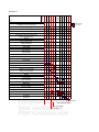
The initial design will be created using Altova XML Spy 2007. Looking at the configuration file created
in Appendix F, it is easy to see the tags that are needed in the schema. What isn’t so clear is the rules that
go with the tags. After discussing certain issues with the Technical Authority, it became clear that there
were certain constraints on each interface the program should work for. The five interfaces that have
been requested to be available in the program are called ‘DTS’, ‘Real Coupler’, ‘SimSaf’, ‘CSH’ and
‘LPD’. The reason these five have been requested is that they are all different and most other interfaces
the company will need the program to work for are based on these five or are very similar.
One constraint on these interfaces is that the LPD interface can only appear once per configuration. The
other four interfaces can appear as many times as the user wishes in each configuration. This means
that in the schema, it would be better to have two different tags for the interface, one which allows any
number of occurances between 0 and infinity and one which only allows the number of occurances to
be 0 or 1.
I think it would be a good idea to create a ‘complex type’ for each of the five interfaces, these would
each specify the format for each interface individually. Each interface follows the same kind of format
but there are differences within them:
DTS
The DTS interface needs to contain the following information: Interface Type which will be fixed to
‘DTS’, Node Id which is a single number ranging from 1-255 (this number is a unique identifier for
each interface type in the configuration), socket and extra information. Each tag must exist and must be
in the order specified
The socket tag needs to contain the following information: Name which again will be fixed to ’DTS‘,
Local IP Address, Remote IP Address and Port. Again, each tag must exist and must be in the specified
23
order.
The Port tag needs to contain the following information: Local Heartbeat, Destination Heartbeat, Management, Reliable, Local Unreliable and Destination Unreliable, all of which should contain integers
and must exist in the order specified.
Finally, the extra information tag must contain the information for Card which will hold a single number, either 0 or 1 which informs the program of which network card the interface should be configured
on.
The DTS Interface can also have an extra option of a ‘Snoop’ being added to it. This basically means
that an interface will be created on both network cards for the given node Id. The specification for this
will be detailed in another tag later.
Real Coupler
The Real Coupler interface needs to contain the following information: Interface Type which will be
fixed to ‘Real Coupler’, Node Id which is a single number ranging from 1-255 (this number is a unique
identifier for each interface type in the configuration), socket and extra information. Each tag must exist
and must be in the order specified.
The socket tag needs to contain the following information: Name which again will be fixed to ‘Real
Coupler’, Local IP Address, Remote IP Address and Port. Again, each tag must exist and must be in the
specified order.
The Port tag needs to contain the following information: Local Heartbeat, Destination Heartbeat, Management, Reliable, Local Unreliable and Destination Unreliable, all of which should contain integers
and must exist in the order specified.
Finally, the extra information tag must contain the following information: Card which will hold a single
number, either 0 or 1 which informs the program of which network card the interface should be configured on, TSM Transmission Method which must hold either ‘DTS Mode’ or ‘VLAN Mode’ and ATE
Enabled which is a boolean and is optional. Other than the ATE Enabled tag, the other two must be
present and in the order specified.
CSH
The CSH interface needs to contain the following information: Interface Type which will be fixed to
‘CSH’, Node Id which is a single number ranging from 1-255 (this number is a unique identifier for
each interface type in the configuration), socket and extra information. Each tag must exist and must be
in the order specified.
24
The socket tag needs to contain the following information: Name which again will be fixed to ‘CSH’
and Local IP Address. Again, each tag must exist and must be in the specified order.
Finally, the extra information tag must contain the information for Card which will hold a single number, either 0 or 1 which informs the program of which network card the interface should be configured
on.
SimSAF
The SimSAF interface needs to contain the following information: Interface Type which will be fixed
to ‘SimSAF’, Node Id which is a single number ranging from 1-255 (this number is a unique identifier
for each interface type in the configuration), socket and extra information. Each tag must exist and must
be in the order specified.
The socket tag needs to contain the following information: Name which again will be fixed to ‘SimSAF’, Local IP Address, Remote IP Address and Port. Again, each tag must exist and must be in the
specified order.
The Port tag needs to contain the following information: Local and Remote, of which both should contain integers and must exist in the order specified. Finally, the extra information tag must contain the
information for Card which will hold a single number, either 0 or 1 which informs the program of which
network card the interface should be configured on.
LPD
The LPD interface needs to contain the following information: Interface Type which will be fixed to
‘LPD’, Node Id which is a single number ranging from 1-255 (this number is a unique identifier for
each interface type in the configuration), socket and extra information. Each tag must exist and must be
in the order specified.
The socket tag needs to contain the following information: Name which again will be fixed to ‘LPD’,
Local IP Address and Port. Again, each tag must exist and must be in the specified order.
The Port tag needs to contain the following information: Link Port, which must contain an integer and
must exist.
Finally, the extra information tag must contain the information for Card which will hold a single number, either 0 or 1 which informs the program of which network card the interface should be configured
on.
Snoop
The Snoop tag is an option from the DTS Interface but it is given its own section as if it is an interface
25
itself. This tag should contain the following information: Interface Type which will be fixed to ‘Snoop’,
Node Id which is a single number ranging from 1-255 (this number is a unique identifier for each interface type in the configuration) and Local IP Address.
Throughout all of the interfaces, the Local IP Address and Remote IP Address tags are of type ‘IP
Address Type’ which is another ‘complex type’ of the formaterm (which is a number between 0 and
255), seperator (which is fixed to be ‘.’), term, seperator, term, seperator and term. This will ensure
the IP Address entered is valid. Validating that the third term is the node Id can’t be done in the XML
schema so it must be validated within the code.
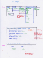
So the overall schema must contain an Interface1 tag which can contain as many of the DTS, Real
Coupler, CSH, SimSAF and Snoop interfaces, followed by an optional Interface2 tag which can only
contain one LPD interface, followed by the following tags which must appear in the specified order:
MaxFileSize which is an unsigned short that must be between 100 and 1700, Network Type which is
a string that is either ‘eth’ or ‘znb’, Default Template Directory which is a string, Override Template
Directory which is a string and Current Setup Directory which is also a string. The Schema used can be
seen in Appendix G.
4.3
GUI
The GUI is an important part of the solution, it is important that it is a simple and clear design that
is consistent throughout the various windows. The two most important aspects of the GUI are the
navigation and the graphics.
4.3.1
Navigation
The navigation between the various windows should be smooth and simple. It is important that the user
knows which window or dialog they are on and they shouldn’t be able to access any previously opened
windows or dialogs without first closing the current one.
It is a good idea to keep the exit or back menu items in the same place on each window so that the user
doesn’t have to search for it. It should be obvious to the user which options involve producing a new
window, and new windows should only be used when necessary.
I think it is a good idea to plan when new windows or dialogs should be produced before designing the
26
whole GUI. It is obvious that the configuration of each interface should produce a new window since
this is a seperate entity.
The current setup of the computer needs to be viewable. This will display the currently loaded configuration, current setup files directory, current override templates directory, default templates directory,
max file size and network card type. I think this should be displayed in a new window also.
The nodes currently set up should also be viewable in a new window. This would be best displayed in
some kind of a table with those nodes configured on card 0 on the left and those configured on card 1
on the right.
If the user wishes to change any of the current setup information, a dialog should appear where the user
should specify the new information. The user should be able to save the changes or cancel.
When the user wishes to load a previously saved configuration, the usual select file dialog should be
produced. This is the same dialog that will be used when the user wishes to save a configuration.
Within the configure interface windows, it should be possible to view the currently configured ports and
also the nodes configured for that interface type. The view of these nodes should be the same as the
view of all of the nodes from the main window so as not to confuse the user. The view of the ports
should be the same kind of view as the current setup from the main menu.
When the user chooses to add a node to an interface, a popup window should be displayed, showing
the various attributes required for the operation. If the user chooses to save the added node, a dialog
should appear informing the user that the save was successful. When deleting a specific node, it is wise
to produce a dialog where the user specifies the node id of the interface they wish to remove.
If the user wishes to change the IP Address, a new window should be displayed with the current information for the node they are wishing to edit. The user should then be able to edit either of the IP
Addresses for that node and then save the node details. Upon selecting ‘Save’, a dialog should appear
informing the user that the save was successful.
If the user wishes to change the port numbers that are configured, a new window should be produced,
allowing the user to make the changes they wish. It should then be possible to either reset the ports to
what they were originally or to save the new port numbers.
4.3.2
Graphics
Although graphics shouldn’t be used too much, it is an idea to use some graphics where possible so that
the user knows what the button does without having to read and take in the label. I think it would be a
27
good idea to use stocks on all buttons possible. Since stocks are used in many programs, they will aid
the user remarkably and speed up any process they are carrying out.
4.3.3
Initial Design
The initial design of the GUI can be seen in Appendix H. It was then sent to the Technical Authority
Manager of SAINTT and their comments were made.
4.3.4
Comments
The comments made by the SAINTT team can be seen in Appendix P
These comments will be taken into account and a new design will be drawn up and approved by the
Technical Authority Manager.
4.3.5
Final Design
The comments made in Appendix P were taken into consideration and my own views used to create a
final design. I thought it would be a good idea (if possible) to have a tool bar at the top of any windows,
as well as menu bars, which display the most commonly used options as buttons. If available, these
buttons will display a stock item for each option.
The final design can be seen in Appendix I. It was approved by the Technical Authority Manager of
SAINTT.
28
Chapter 5
Implementation
This section details the implementation of the solution for my project. It outlines any problems occured
and how each problem was fixed or overcome.
5.1
GUI
The first part of the implementation was the GUI. After carrying out background research (section
2.4.4.3), I decided it would be most efficient to use ‘glade’ to design the GUI. When doing this, I
followed the design produced (Appendix I) as closely as possible and at all stages I named each widget
and component with self explanatory names for later use within my code.
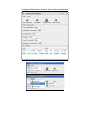
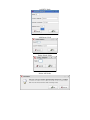
Creating the GUI within Glade proved to be simple and efficient and it enabled me to get the GUI to
look exactly how I wanted it to look. A selection of the windows can be seen in Appendix J.
5.1.1
Problem I
After creating the GUI using Glade, it was time to begin coding and get my program to produce the GUI
on startup. Again this seemed to be very simple and, after using Glade tutorials [11, 12] I had the GUI
being produced as required.
The next step in the tutorial was to connect the signals for all widgets that required something to happen
29
when clicked/changed. In order to do this, when creating the GUI, I had to attatch signals to every
widget this was needed for. In order to connect the signals, one simple method had to be called in my
code. Following the tutorials, this method had to be called after loading in the Glade XML file. After
compiling the code, I ran the program but many warnings were produced informing me that it could not
find the signal handler for every signal I added to the GUI.
I checked my code thoroughly against the tutorial and used a debugging program called gdb on linux
to check what line of code was producing the errors. Sure enough it was when calling the method to
connect the signals that all the warnings were appearing. No matter how much I checked my code and
looked at the tutorials, I could not see the problem.
I contacted two previous colleagues who worked with Glade while I was working on SAINTT, explaining my problem. They both suggested various things to try but to no avail. I contacted the Technical
Authority at SAINTT, telling him of my problem, but no one was able to work out the problem.
Getting desperate, I joined a forum that had a newsgroup for people having problems with Glade [16].
I posted my question but never got a response. I also replied to a thread on the Glade website asking
someone who had previously had the same kind of problem if they found a solution and if so, what it
was but again got no reply.
Finally, I joined the school of computing newsgroup for C++ but no one replied to my post. I then
decided I was getting too far behind schedule to continue like this, it was time to make a decision. Appendix K shows the code I was using and the warnings produced, along with some of the emails I sent
and received along the way.
5.1.2
Solution I
I now had two choices. I could either manually connect every signal or I could create the whole GUI
from scratch manually (by coding). I thought it would be a good idea to try to manually connect every
signal since it would take less time that coding the whole GUI manually and it was possible to test
the solution by first connecting just a few signals, minimising the amount of wasted time should this
solution fail too.
[17] explained how to do this. So, following the book I began manually connecting some of the signals
on the main window. The following method was added to one of my files and called as soon as the
Glade XML file had been successfully loaded:
30
//method to connect signals to widgets
void Callbacks::connectSignals(GladeXML *xml)
{
//obtain widget to connect signal to
GtkWidget *currentConfigBrowse =
glade_xml_get_widget(xml,"currentConfigurationBrowseButton");
//connect signal to button
gtk_signal_connect(GTK_OBJECT(currentConfigBrowse),"clicked",
GTK_SIGNAL_FUNC(
on_currentConfigurationBrowseButton_clicked)
,NULL);
}
5.1.3
Problem II
This solution didn’t get me very far. I had the same problem as before, the signal handlers couldn’t be
found. This meant that I only had one solution left.
5.1.4
Solution II
I decided rather than coding the whole GUI from scratch, that I would use a library called gtkmm which
provides basic code for all types of widgets and GUI components. All you have to do is compile your
code with this library and then you can use inheritance to use the pre coded GUI components. This
makes it a lot quicker and easier to create the GUI. For example, when producing a window, you inherit
from the gtkmm window class and use simple methods to adapt the window to your preferences. For
example, set title(‘title of window ’) allows you to set the title of the window to the title you want.
I used many tutorials and API websites to help me produce my code ([18, 19, 20]). This was quite time
consuming but once complete, the GUI worked fine, with no problems.
These problems made me quite behind schedule and it was due to this that I had to re do my Gantt chart
to re schedule all the tasks I had left to do.
31
5.1.5
Final GUI
The initial creation of the GUI was acceptable but not perfect. On the main window and within each
configuration window, there is a table that displays the nodes configured on each interface. The initial
GUI displayed the correct information but there were spaces between nodes which didn’t look that good.
I had a look at the gtkmm tutorial [18] and discovered a different widget that allowed you to specify
which row and column text was entered to. I realised this would solve my problem but when I tried to
use the new widget, I discovered that the version of the gtkmm library I was using was older than the one
that had the new widget I wished to use. Therefore, I had to find the source code ([19]) and incorporate
it within my code. This proved to be relatively simple since the new widget simply used widgets that
I was already using but manipulated them to do other things. This meant that I could just replicate the
code within my code and even meant I could personalise the code to be more suited to my program.
Both versions of the GUI can be seen in Appendix L.
5.2
File I/O
After realising that trying to solve my GUI problem may take a while, I decided it would be beneficial
to begin coding the file input and output since I didn’t really need the GUI to be able to do this. As
decided in section 2.4.2.3 I am using XML for my configuration files. In order to read in and write out
XML, a libray called xerces is needed. [21] contains an API which proved very useful in coding the file
I/O.
In order to write the code to read in the XML file, I needed to closely follow the schema created
(Appendix G) since reading in is done as a tree; reading in a node and then moving on to it’s child/sibling
and reading in that node. It was a very sequential process to read in the XML file and apart from a few
‘blips’, it went very well.
The main problem I encountered was that there was an extra node after each tag but before the text
within the tag. This meant that the first time I tried to read in an XML file, it crashed. This was because
I was trying to access certain nodes in a way that wasn’t possible for their type. It took a little while to
discover what the problem was but once discovered and the relevant alterations made, my program read
in an XML file perfectly.
It was important that I remembered that the configuration file being read in could contain many sections
detailing each ‘interface’, eg it is possible to have up to 50 DTS interfaces in one configuration. In order
32
to allow for this, many loops had to be coded in to ensure I allowed for many of each interface.
As the file was being read in, it was important to store the information required to be displayed since
later on it would need to be passed to various other classes in order to display it in the correct places. In
order to do this, a simple conversion needed to be made since by default the information obtained from
the XML file is in a type specific to xerces. This conversion creates a C++ string which can then be used
simply.
After reading in the file, various variables had to be deleted or shut down so as to prevent memory leaks.
When thinking about how the program was going to be used, I decided it would be best to write out
a temporary XML file everytime the user pressed the ‘save changes’ button in the configure interface
windows. This is because it was easier to update the main window’s display of configured nodes by
reading in an XML file.
So, when the user pressed the save changes button, a method would be called in the configure io file
that wrote out the configured nodes to a temporary XML file. This file would then either be deleted or
renamed depending on whether the user decided to save their configuration or just quit without saving.
Writing out XML using xerces was also quite simple. Again a conversion was needed to convert the
strings into the xerces form of a string and then the reverse method used to retrieve the information was
used to write out the information. Before actually writing the information, each tag had to be created
and inserted into the XML tree in the correct place. Again, loops were required where there were more
than one of the same interface configured.
Once all the tags and information were written to the file, the file was closed and again, certain variables
were deleted or correctly shut down to prevent memory leaks.
5.3
Validation
When the user enters information to the program, it is important that it is validated. This is to ensure
that incorrect information is not written out to the XML files and that no problems occur later in the
program. There are various different validations required.
5.3.1
Node Id
The node Id entered for each configured node must be a number in the range 1 → 255 inclusive. It
must also be unique to the nodes configured on each seperate interface. (e.g a DTS node 3 and Coupler
33
node 3 are allowed but two DTS node 3s are not allowed). So, when the user enters the node Id being
configured, it must be checked against all existing nodes on that interface. If it already exists, when the
user presses the ‘OK’ button, they are informed that the node already exists and they are then displayed
with the same dialog so that they are able to alter the node Id to something different.
5.3.2
IP Addresses
When the user configures a new node on any interface (node here is referring to the collection of IP
Addresses and node Id on each interface), the IP Addresses must be unique. The way the GUI is
set up, when adding a new node on a certain interface, the user is prompted to enter the node Id and
IP Address(es). When the node Id is entered, if the user presses the return button, the default local IP
Address (and Remote IP Address if applicable) is automatically filled in. The user is then able to change
this if they wish. When pressing the ‘OK’ button, the information in the IP Address entry box(es) is
obtained and run through a series of checks. First of all I check if it is the default IP Address, since if
it is, no further checks are required. If it isn’t, I then check that there are 4 terms (4 numbers) and 3
sperators (.’s). If this test is passed, I then check that the four terms are all numbers in the range 1→255
inclusive. No matter what address the user enters, the third term of the address must be the same as the
node Id being configured. Therefore, if all other tests are passed, the next test is that the third term is the
same as the node Id entered. Finally, a test is carried out to ensure that no other configured node has the
same IP address. If at any point in the validation the test fails, a string is set to hold information of the
error that has occured. At the end of the validation, this string is passed back and if there is text stored
in it, an error message is brought up explaining the error and the user is shown the ‘Add node’ GUI they
were previously at so that they can fix the problem.
5.3.3
Network Card
The user selects the network card they wish the node to be configured on by using a combo box which
contains the options 0 or 1. If when pressing the ‘OK’ button, one of these numbers hasn’t been selected,
an error message will be produced informing the user. They will then be displayed the same ‘Add Node’
dialog so that they can rectify the problem.
34
5.3.4
Port numbers
The different interfaces that can be configured using the program have various ports that must be specified. It depends on which interface you are configuring as to how many ports and which ports they are.
In all interfaces, the ports specific to them must be different to each other. (eg no two ports in the DTS
interface can be 6000 but one port in the DTS can be 6000 and one in, say the LPD interface can also
be 6000).
Since the port numbers are stored in the XML configuration file that is read in, a check must be made
before updating the port numbers within the configure interface windows. If there is an error at all, the
default values will be used instead of those entered in the XML file.
It is possible for the user to change these port numbers. When doing so, a check is made every time to
ensure the port number is valid. Since it is possible that the user has entered two port numbers round the
wrong way, to ensure it is possible to swap them back, I decided it would be a good idea to let the user
enter the port number and then prompt them to change the other port number that is the same. So, if the
user has the ‘management’ port set to 6000 and the ‘reliable’ port set to 6001 but they want them to be
the other way around, if they change the management port to be 6001, a message will appear informing
the user that they must change the reliable port number and upon acknowledging the message, the reliable port number will be highlighted so that they can simply type the new port number straight away.
These checks are all done by using signals for when the user clicks in or presses enter in an entry box.
When the signal is emmited, a method is called which retrieves the information in the specific entry box
and then calls all the relevant validation methods required.
On top of this, there is another specification between the port numbers stored in the DTS interface and
the Real Coupler interface. Both interfaces have the same ports, with the same names. The way these
two interfaces are used by BAE Systems means that certain port numbers in the DTS must be the values
of other ports in the Real Coupler interface. Therefore, when either the DTS or Real Coupler ports are
changed, the other must also be changed (this will be done automatically). The pairs of ports that must
be the same are as follows:
Local Heartbeat & Destination Heartbeat
Management & Reliable
Local Unreliable & Destination Unreliable
35
5.4
Global Data
It is a good idea when coding a program not to hard code anything. That is, it is not advisable to write
something like ‘open(‘/directory/folder/file.extension’)’ because if this ever changes, it is hard to locate
it within the code. Instead, it is a good idea to have a file called ‘global definitions’ or somthing similar
in which you create a constant variable every time you need to ‘hard code’ information. These variables
are generally written in capital letters so that throughout the code it is clear that the variables are stored
within the global definitions file. The variables created within this file will be available to all classes that
include the global definitions file. This idea is also more efficient since it prevents duplication of data in
some cases. For example, if there is a constant string that is needed in more than one class, rather than
create it in each class it is required, it can just be created once in the global definitions file and then the
classes that need access to the string can include the file.
5.5
IP Aliasing
The final part of the program is to create the physical IP Addresses on the computer. The way this is
done is to edit the scripts that are run on startup so that one of them calls another script which I will
create. This script must ensure that the network cards are ‘up’ and after ensuring this, must then run two
scripts that are created by my program. This script needs to contain the following:
/sbin/ifconfig eth0 down
/sbin/ifconfig eth1 down
/sbin/ifconfig eth0 up
/sbin/ifconfig eth1 up
/home/saintt/.ip_aliasing0
/home/saintt/.ip_aliasing1
Where .ip aliasing0 and .ip aliasing1 are the two scrips created by my program.
These two scripts (one for card 0 and one for card 1) contain code to set up the physical IP Addresses.
To do this, each script must follow the same kind of format as follows:
#Number of aliases: 1
/sbin/ifconfig eth0:0 1.2.1.3
/sbin/ifconfig eth0:0 netmask 255.255.255.0
36
Where the number of aliases is the number of nodes configured on that card. Where it says ‘eth0:0’ this
should be the network specified (eth or znb) followed by the card (0 or 1) and the number after the ‘:’
should increment so that if there are two nodes, the second node will be ‘eth0:1’, for example. For every
node there should be a line that specifies the IP address and one that specifies the netmask. These scripts
must be written when the user saves their configuration. The number of nodes (aliases in this case) was
obtained by going through the structure containing all of the nodes and checking which network card
they were configured on. Then a for loop was used to write out each node on each card, accessing the
IP Address from the structure.
After the user quits the program, a message is produced prompting them to reboot the computer. This is
because when they reboot the computer, the scripts are run and the physical addresses are created.
37
Chapter 6
Testing
Testing is an important part of programming, I feel it is a good idea to test certain things along the way
and then, after completion, carry out a test on the whole program to ensure everything works how you
expect it to. It is often the case that when new functions are added, they can ‘break’ other functions that
previously worked. Therefore, it is possible that without testing everything once it is all complete, there
are errors within the code that you didn’t realise.
6.1
Phase I
The test schedule can be seen in Appendix M
6.2
Problems and Alterations
As can be seen from Appendix M, a few errors were encountered. One was pretty major and meant I
had to abort the test.
The first error is quite easy to fix. When the user is selecting a file to load, it must be an XML file. There
is a filter you can add to the dialog to tell it to only show files of a certain type. At the moment, it is
allowing only plain text files to be displayed, this must be changed to allow only xml files.
38
The second and third errors are similar and can be fixed in the same way. When the file selection dialog
appears for two of the browse buttons, the user is supposed to be selecting a folder but the dialog only
allows them to select a single file. After researching the File Chooser Dialog, [22] proved to be helpful.
Previously, I have been creating the Dialog by passing a string that tells the dialog that its purpose is
to open a file. There is a different string that you can use if you want to select a folder instead. So by
simply adding a ‘bool’ to the run method that creates the dialog, I can perform a check and create the
dialog in the correct way.
The last error discovered through Phase I testing is caused because when the user saves their configuration to another file, any alterations that are then made and saved aren’t saved to the main configuration
file. This main configuration file is the file that is automatically opens when the program is started. To
fix this problem, when the user presses the save button, the sampleConfigFile.xml file should also be
updated.
6.3
Phase II
The test schedule can be seen in Appendix N
6.4
Problems and Alterations II
As can be seen from Appendix N, more errors were encountered. The test was aborted since one of the
errors affected the rest of the test.
The first three errors are linked, the problem being that when a file is saved, the values in the entry boxes
and combo box aren’t saved. This should be a simple fix.
The last error seems to be that the DTS Window is reproducing the node added even though the changes
were discarded. This is due to there being an error in the code when the discard changes button is
pressed. The code deletes the node that was added but then the next bit of code adds back any nodes
that were deleted. To fix this, a check will need to be made so that it only adds back nodes that were
actually deleted via the delete buttons.
6.5
Phase III
The test schedule can be seen in Appendix O
39
6.6
Problems and Alterations III
As can be seen from Appendix O, there were no problems with the test. The only alteration that could
be made (but isn’t necessary) is to ensure that after loading a previously saved files, when adding a new
node, it is entered in the correct row of the DTS Nodes table. This doesn’t affect the performance of the
program so isn’t really required.
6.7
Phase IV - Final Testing
The final testing was performed by the Technical Authority of the SAINTT team.
6.8
Problems and Alterations IV
No problems were found when the program was tested by the Technical Authority Manager of the
SAINTT team.
40
Chapter 7
Evaluation
It is important to evaluate the product thoroughly with respect to both the functionality and the usabilty
of the system. The evaluation should be sure to look into detail that the product suits all the requirements
made by the company and that at least the minimum requirements are met. As well as this, the impact
the system has on the prospective users is also important and should be taken into consideration. Finally,
it is important to critically evaluate the system as a whole, detailing any problems or limitations that may
have occured.
7.1
Evaluation Criteria
The following evaluation criteria are used to help with the whole evaluation process. They greatly help
to make a conclusion as to whether the created system is a success or not.
7.1.1
User Requirements
BAE Systems provided a document (Appendix B) outlining the problem and within the document,
certain user requirements can be seen. Table 7.1 shows the User Requirements and whether they were
satisfied. Table 7.1 can be backed up by the test steps and results (Appendicies M, N and O), GUI print
screens (Appendix L) and the Company evaluation (Appendix T).
41
Requirement
Degree of Satisfication
The main window should display the default tem-
Fully satisfied
plates and the configured nodes
From the main menu the user should be able to
Fully Satisfied. In order to edit the values, the user
edit: Setup files directory, Override Template direc-
has two options; they can manually enter the Value
tory,Maximum file size and Card type.
or click the ‘browse’ button located to the right.
The user should be able to save configurations and
Fully satisfied. The file selection dialogs are set up
load previously saved configurations
to ensure the correct file type is selected (or folder).
The user has the choice to save over the current configuration or save the file to a new name.
The user should have access to the setup for each
Fully Satisfied via the ‘Configure Interface’ menu
interface type
item
The interface window should display a more de-
Fully Satisfied. If no port numbers are in the config-
tailed summary of the nodes currently set up on that
uration file, defaults will be displayed
interface, including the node id, IP Addresses and
Port numbers
When a node is added, the default IP Address will
Fully Satisfied. If the user chooses to change the
appear. This can be changed if the user wishes
value, it will be fully validated
The port numbers can be changed
Fully Satisfied. In some cases (for the DTS and Coupler interface) setting the port numbers in one interface automatically sets the port numbers in the other
User input will be validated at all stages
Fully Satisfied. If an entry is invalid, the user will be
displayed an error message detailing the problem
Defaults should be used where appropriate. If the
Fully Satisfied
user loads an invalid file, the default values for the
setup and ports should be used
The program will output a file representing the con-
Fully Satisfied
figuration
The program should read in the current configura-
Fully Satisfied
tion on start up
Table 7.1: Evaluation of User Requirements
42
On top of the specified User Requirements, it has been verbaly agreed that the program should be reliable
and have a good usability (see Section 7.1.6). [23] defines reliable as
giving the same result on successive trials
When testing the software, the test sheet was run on three successive occasions and, apart from those
steps that previously failed, the results were the same on each test. (See appendicies M, N and O).
7.1.2
Aim & Objectives
As can be seen from section 1.5, if the objectives are met, the aim is also met. Table 7.2 shows the
Objectives and how well they were satisfied. Although all the objectives were met, it should be noted
that there are limitations in relation to more general solutions. Firstly, the specification of each inteface
is pre defined within the code so it is not possible to use the program to configure any interfaces other
than those already coded. Secondly, it is not possible to define any new interfaces so that the program
could be used to configure interfaces other than those already coded since the additional functionality
was not completed (see Section 7.1.4).
7.1.3
Minimum Requirements
In addition to meeting the Objectives, it can be said that by completing the minimum requirements that
the aim is fulfilled. All of the minimum requirements were met:
View and Edit configuration files - The tool displays the currently loaded configuration on start up.
The user is then able to edit/delete any existing nodes and add new nodes to the interface. When saving
the file, the user has the option to save over the current file or save the file to a new name. This can be
seen from the screen shots of the GUI - Appendix L.
Manage and Load previously saved configurations - The tool lets the user load previously saved
configurations. This can be done via the Load button on the tool bar, the File → Load menu item or the
first browse button on the main menu. When saving an edited configuration file that the user has loaded,
the program updates the current configuration file as well so that on reboot the correct IP Addresses are
configured.
Enforce correct syntax of input and output configuration files - A schema is used to enforce the
syntax of the XML file being read in as well as those being written out. If the user loads a file that has
an incorrect syntax, the user is presented with an error message informing them of this and the program
43
Objective
Degree of Satisfication
Design and produce a GUI for the tool
Fully Satisfied - see appendicies H and I for
design and L for implication
Enable the tool to read in previously saved
Fully Satisfied. Upon reading in the file, the
configurations
appropriate fields are filled in and displayed
Enable the tool to write out configurations
Fully Satisfied. The current configuration file
that are to be saved
is automatically updated when saving. If the
user saves to a different name, a new ouptup
file is created with the desired name
Ensure validation of all information entered
Fully Satisfied. Some of the errors produced
by the user
can be seen in appendix L
Design and produce a schema to ensure vali-
Fully Satisfied - see appendix G
dation on input and output configuration files
Fully test the tool before delivering to BAE
Fully Satisfied - see appendicies M, N and O
Systems for feedback
Take any points brought up by the company
Fully Satisfied - see Appendicies H, I and P
and amend the tool as applicable
Table 7.2: Evaluation of Objectives
44
displays the current configuration file. If the syntax error is on loading the current configuration, the
program will fill in the required details with default values and leave the rest of the configuration blank.
Validate user input - Every field that the user is allowed to edit or manually input is validated. The
validation is carried out against the previously agreed set of values for each field. The user is informed
of their error and directed back to the window containing the error so that they can make the necessary
changes. No errors are ever written out to a configuration file.
7.1.4
Additional Functionality
The program contains some additional functionality that wasn’t planned. For example, there are toolbars
on the windows to improve usability as well as tool tips and short cuts.
On top of that, a user guide was created - see Appendix Q.
7.1.5
7.1.5.1
Methodology
Design
As planned, with regard to gaining feedback from BAE Systems, the design of the GUI and schema followed a sequential methodology that (thankfully) only cycled round twice. Both designs had comments
made on them which I considered when re designing. In both cases, when producing the new design to
BAE Systems, there were no comments made.
Coding the program also followed the planned methodology since I followed a sequential methodology
again. As predicted, there were occasions where I had to go back to certain parts of the code to alter
either a problem or to alter it due to something I hadn’t thought of at the time. For example, instead of
coding both the input and output in one go, I coded the input and then went onto the next section of code
- updating the GUI. In the initial plan, I had neglected the fact that the GUI would need to be updated,
and so I had to go back to the GUI classes and add in the required code. Once this was complete, I
continued back to writing the output code.
The inital milestone for completing the GUI wasn’t met due to unforseen problems. When creating a
new schedule, a new milestone was created. Although I didn’t manage to complete the GUI by this
milestone either, it was only one week late. The milestone for completing the coding was also one week
late. I managed to deliver my product to BAE Systems at the time of the milestone, although it took a
week longer than planned to receive their test results and feedback.
45
7.1.5.2
Write Up
As planned, I wrote up this report as I went along. As soon as I completed one section of the coding, I
made a note of how it went etc. After completing the program, I was able to go back to my report and
alter what was written to make it more suitable for a report. I followed the same methodology for the
testing section of the report to ensure all the results of the tests were recorded accurately and all solutions
were written up as I made the necessary alterations to my code. This meant that no information was
incorrect or forgotten.
The milestones completed were met, both the mid project report and final report were delivered on time
and to schedule.
7.1.5.3
Testing and Evaluating
When testing the program, I followed my planned methodology. I created a test sheet which was filled in
on all phases of testing (see appendicies M, N and O). After completing a test (or aborting due to errors)
I made the necessary amendments and then repeated the test sheet. I made sure that I tested functions
that previously passed the test since it was possible that my amendments had caused unwanted problems
in those areas that previously worked. In total, I had to carry out three test sheets before my program
passed all steps.
After passing my tests, I passed the program on to the SAINTT Technical Authoroty Manager for him
to test and evaluate (see Section 6.7 for information on the test and Appendix T for the evaluation)
Also as planned, I constantly tested my program while producing and updating it. Although it was clear
from the test sheets that this testing alone wasn’t good enough - there were many small bugs I hadn’t
picked up along the way.
7.1.5.4
Problems
I encountered a few problems along the way, mainly with the coding of the GUI. As a result of the
problems incurred with the GUI, it was necessary for me to create a new schedule. The changes made
were required since I incurred a severe delay due to the problems that occured. This entailed pushing
back the schedule for the functionality that hadn’t yet been coded. Although I did this as planned,
looking back, I think it would have been more beneficial to have done this sooner and given up on the
original plan for coding the GUI before I did. This would have given me more time to complete the
46
coding and to have added in the additional functionality. As it happened, I had to change my plan for
creating the code for the GUI, twice. Both times, I discussed the change with the Technical Authority
and agreed on the new approach. Both version of the Gantt chart can be seen in Appendix C.
7.1.6
Usability
The usability of the program is one of the most important aspects. If the program isn’t easy to use
or pleasing to the user, it will fail. As can be seen from the background reading (section 2.4.4.1) and
Appendix R, I looked into the design of the GUI in great detail before designing and creating it.
The program produced has a good usability, there is a tool bar on all windows that provides the main
functions that are most likely to be used. These functions can also be accessed via the menu. I ensured
that the design of all windows was the same and that the layout of each was very similar, if not identical.
This helps the user since they get used to certain options being in certain places and it would cause
confusion if certain things weren’t consistent. For example, I ensured that on all dialogs the left button
was the cancel or quit button and the right button was the ok or open button. This prevents the user
selecting the wrong option by accident after they have used the program many times and got used to the
layout.
As can be seen in Appendix L, the initial GUI wasn’t as perfect as I would have liked - although it
worked correctly, the look it gave to the user wasn’t very professional and so I altered how the GUI
displayed the configured nodes so that there were no gaps in the tables.
I ensured I used Stocks for the menu and toolbar options where they were available. These are the small
picture symbols attatched to the option, like a floppy disk by the save button for example. I feel these
add a great benefit and help the user if they are less experienced or new to the program. I also added
shortcuts to the menu items where possible so that the user is able to use key commands to call certain
menu items. This also adds to the usability as it means that people without a mouse can also use the
program. The last addition I made to the tool bar and menu items was that I added in ‘tooltips’ where
possible to give the user more explanation of what the menu/toolbar item will do. This is another benefit
for those less experienced and new users.
In order to test if the program has good usablilty, it was passed onto the Technical Authority of the
SAINTT team for their view:
The program seems to have a good flow between the various screens and a simple yet
effective display. The addition of tool tips and the tool bar make the program particulaly
47
user friendly as they insure that those users with less experience of running the program are
lead in the correct direction. When using the program myself, I found it easy to use and
I had no difficulty in accomplishing the tasks at hand. Overall I feel the usability of this
software is very good
7.1.7
Additional Functionality
It was a shame that I ran out of time to include the ‘add interface’, as it would have been of great
use to the company. This function was always going to be a bit ambitious due to it’s complexity. In
order to produce a function that worked correctly and as generaly as needed, it would require a detailed
input from the user. Details of the kind of information that would need to be obtained can be seen in
Appendix U. The vast amount of information required indicates the complexity of this function but the
actual coding would be a lot more intricate. After obtaining details of the specification from the user, the
program would have to produce the correct code within the correct files to ensure all functions can be
performed on the new interface. A window would need to be created in which the user would configure
the interface. This window would need to contain the relevant fields for the user’s input and at the same
time must validate the data. On top of this, the new window would need to be linked in with the main
window and the other function windows (adding/deleting nodes etc) to ensure all necessary fields are
updated when required. As can be seen, this would be very time consuming but at the same time very
beneficial, it is unfortunate that the problems with the GUI took so long to resolve or this functionality
could have been attempted.
The User Guide will be of great use to the company and the SAINTT team members. Writing the User
Guide went very well and smoothly with no problems. I managed to follow the planned methodology
and run the program at the same time as writing the User Guide to ensure every detail was correct.
Although at the time of evaluating I did not deliver the User Guide, it has since been sent to the team
and their feedback was as follows
The User Guide contains all the relevant information needed to run the Confuig Utility. The
layout is in website form (as specified). From a website point of view, it is simple and to the
point which is good since the general user will most probably be those with little technical
knowledge or those new to SAINTT. In all, the User Guide will be of great benefit and we
are able to add it on to the User Guide for the rest of SAINTT.
48
7.1.8
Testing
I feel the testing carried out was very efficient. By ensuring all test steps were carried out every time the
test was run, I ensured that there were no bugs left in the system. Of course there could be bugs that I
have not come across but by passing the program on to BAE Systems, I hoped these bugs would also be
found.
Considering on the first run of the test I had to abort, the testing and fixing section of my project didn’t
take that much time. Most of the problems encountered were easily solved and solved correctly first
time.
By performing two different types of testing (by myself and by someone else), I ensured that at least
99% of bugs were found and fixed. Using a secondary tester is also a benefit since they are more open
to finding errors that I was unable to find - this is because they aren’t used to the program and may try
different chains of events or may make a mistake that shows up a bug. Overall I was impressed with my
testing and making amendments.
7.1.9
Company Evaluation
An evaluation of the program, produced by the Technical Authority of SAINTT, can be seen in Appendix
T.
In regards to the improvement features mentioned in the evaluation, I agree that porting to libglade is
an area for improvement. It was always my intention to create the GUI using libglade (refered to just as
Glade throughout this report) and, had the problems I experienced not occured or had they been fixed,
this would be the case. When creating the menu items, I allocated an accelerator key to most of the
functions but I did not get round to producing the coding to implement them. These would have been of
great benefit to the more experienced and frequent users.
7.1.10
Improvements
Looking at the program as a whole, there are a few improvements that could be made to it. Firstly, a
function to enable adding new interfaces to the program would be implicated, a function I had wanted
to include but ran out of time.
Another improvement would be to allow the user to click into the tables containing the configured
nodes and edit the details that way. This would be a benefit to the user since it would make it quicker
49
for the user to edit their configurations. It would also be beneficial to allow the user to ‘right click’ on
a configured node and have the options to delete or edit the node - this again would enable the user to
speed up the process.
7.1.11
Comparison of Other Products
Whilst carrying out research and when evaluating my program, I studied various resources in an attempt
to find a product that would perform some of the functions my solution displays. I searched on the internet using various search criteria but could not find anything remotely similar. With regard to creating
the physical IP Addresses, I could only find guides to take you through step by step how to do it, there
did not appear to be any existing software that would do this for you. As for the rest of the program, I
was unsure of what kind of program to look for. I tried ‘configure interfaces’, ‘setting up networks’, ’IP
configuration tools’ and many other variations but to no avail.
Since there were no real other products that could have been used for this, my program compares very
well.
The program required was so specific to the company that it would have been impossible to use any
existing product anyway. Since it was so specific and since my program meets all requirements, the
program is very successful.
50
Appendix A: User Reflection
As a whole I found this project quite enjoyable. Although it proved to be quite stressful at times and
there were times when I just wished it would all be over, when it was going well I found it interesting
and good practice for real life.
Having previously done a project in my second year (for SE24), and carried out a years work placement,
I felt I had learnt quite a lot about project management and time management. However, on both previous occasions I had worked within a group and wasn’t prepared for how different working alone would
be.
I feel the following ‘tips’ may be beneficial to prospective Project students:
Use LaTEX as soon as possible
If you are advised to do your report using LaTEX, I would advise you start using it as soon as possible.
Although it isn’t that hard a program to deal with, it can take a while to get used to the format. It can
also take a while to work out how to do certain things in LaTEX, like creating tables for example. Also,
it takes up a lot more time if you first write the report in Word and then transfere it to LaTEX. This is
due to the fact that the files must be written in a .TEX file which must have no formatting in it.
Plan your program
Everyone knows it but very few do it. Planning your program code is an essential must for completing
this project. As I experienced, problems occur where you least expect them and can severely delay your
programming. It is a good idea to allow more time than you expect for each section of the coding as
it never works out as planned and this way you shouldn’t end up behind schedule (much.). Planning is
51
also a good way of preventing errors because it makes you think about what you are doing before you
do it. Once possible errors have been identified, it is a lot easier to ensure you don’t get stuck behind.
Usability
If you are designing a program to be used by people (what other kind of program is there?), ensure you
take the look and feel of the program into account. Try to put yourself in their shoes and keep them in
mind throughout. The system must meet the requirements of the user and it should be simple and self
explanatory. The user has to ‘enjoy’ using the program in order to maximise the functionality of the
system.
Think about your workload
It is important to look at how many modules you are doing in each semester and how much work you are
going to be set. The way I chose my modules worked out extremely well. Although I split my modules
50/50 between the two semesters, I chose them so that in the second semester I only had one module
which required coursework. This meant that I had lots of spare time in the second semester which is
when the majority of the project was completed. Since there is always a rush near the hand in date, I
would advise prospective students to choose their modules with this in mind.
Be sure before doing a project for a third party
If you are considering doing a project for a company or third party, make sure you really think about it.
The problem must be suitable for the project and even though you may think this is the case, others may
not. If possible, talk the problem through with someone within the Project team before hand. I advise
talking to the company or third party before carrying out the project to explain that you may need to
alter certain aspects in order that it suits the project.
When doing my project, I found it very hard to explain exactly what it was that BAE Systems wanted
from me and although my project was approved and my suporvisor agreed it was suitable, it became
clear at my progress meeting with my assessor that he was unsure it was.
Based on my experiences, I wouldn’t actually advise chosing your project to be for a company, I feel it
caused more problems than had I have done a project where the problem was specifically written with a
project in mind.
52
Appendix B: Tasking Memo
The following document is a Tasking Memo provided to me by the SAINTT team at BAE Systems. It
contains details of what the problem is and some requirements for the solution.
53
!
"
!
%
(
&
'
"
"
"
"
!
! "
!
"
*
, !!
"
"%
"
)
"!
!
!
'
!
"
"
"
.
%
#
"
" "%
#
#
!
'
!
' "
%
!
% #
"
#
!
'
!
(
!!
4
4
!
"
#
%
"
#
#
2
!
5' '
"4
! "6 (
! "
"
2
%
#
"
#
#
!
/
"
%
"
2
"
"
!
#
2
2
2
7
#
!
0
2
31 -
#
,
"
"
1 -
!
+
"
-
#
!
!
•
•
•
•
•
•
•
•
•
&"
'
*
# "
!
!
!
$ %!
!
#
"
"
#
""
!
%
%
#
!
!
%
"
!
! "
!
"
"
#
-
$
•
!
-
!
-
•
!
"
!
)
!
'
$ %
" %
"
!
%
#
"
!
"!
4
&
"
"
!
! "
"
'"
%
#
"
%
#
#
' (
8
!
"#
!
%
) %
9
*
*-
+
+
,
,
:
#
*-" ( .
"
/(
!
0
!
1
# " ## !
' ' #
%
#
! "
" $
•
•
"
5'
"
"
•
)
•
! "
.
!
!
;
#
'
#
•
"
•
!
9
!
!
,
"
"
! !
! "
,2
"
"
' "!
!
"
"!
""
#
' "
"
!
%
"
!
"
%
"
!
"
"
!
!!
:
*-$ +
"
*"
' !
#
+ !
!
!
"
!
"
8
#
!
!
!
!
"
!
!
!
!
"
'
"
%
.
.
"
""
"
<
!
8
!
"
%
"%
""
#
"
#
' "
"
""
"
"
'
!
#
:
#
# ! #
"
=
"
!
"
>
"
", !
&!
!"
!"
/'
"
@
!
" "
*
!
*
"
&!
!
%"
#
!
!
,
'
! %
#"$%
#"$%
(
2
%
# A
&!
!
%"
#
!
# ! #
!
#
!
"
#
""
"
" #
#
9
?
!
"
%"
#
! !
"
/
#
!
"
!
"
"
"
"
%
.
!
# ! ! "
%
"
&!
%
%"
)
'
#
11 B
#
"
!
%
!
"%
!
"
!
8
C !
'
3
!
4
!
56
7
# !
"
)
" "
#
%9
!
' "
"
! 8
(
!
"
"
!
"
% "
!
#
-
' "
"%
'
%
!
%
Appendix C: Gantt Charts
This appendix shows the first Gantt Chart created and then the revised schedule once it was clear that
coding the GUI wasn’t working.
57
?
"
&
"
"( ?
-./
"
(
%) %
8
>?
%)
9
@
-
1 "( -./
' ( -./
* " =9
3
%)
&
1
; 1
1 2
/
)
1 2
3
1
< )(
1
0
-./ 22
% ) / ("
; )
" ("
"
9
3
"
(
/
3
31
&
*
1
)
'7 9#
" 3
(
&
:
, (
.
*
7
'((
)
)"
8'
&
-./ 0
* +
, (
"
)
()
1
* (
' " )
2
22
0 "
222
3
1
#(
1
-./
)
)
4
5 )
() "(
) 6
3
(
")
9 31
'7
'( )
'( )
'( )
$
" "
3
*
'( )
&
&
$
&
" #
%
&
" #
" #
%
%
$
" #
" #
!
" #
%
" #
!
" #
!
!
" #
!
$
/*
'( )
'( )
'( )
&
'( )
&
$
$
&
%
&
%
$
%
%
/*
" "
*
?
"
&
"
"( ?
-./
* (
' " )
%
"
(
%) %
>?
8
9
%)
@
1 "( -./
'
*
"
( -./
-
=9
3
&
1
; 1
1
)
/
1
3
1
< )(
1
0
-./
% ) / ("
; )
/
" ("
"
9
%)
3
"
3
(
31
&
*
)
'7 9#
&
1
:
(
"
, (
.
*
9 )"
*
7
'((
3
)
)
)"
8'
0
)
0
-./ 0
0
()
9 31
()
()
'7
, (
Appendix D: Past Configuration File
An example of the old configuration file can be seen in the document in Appendix B or here:
INT LEN_THIRD_PORT 20001
INT LEN_SECOND_PORT 20002
INT LEN_FIRST_PORT 20003
INT MAXIMUM_FILE_SIZE 500
STRING LOCAL_LEN_IP_ADDRESS_23 "164.23.46.1"
STRING LOCAL_LEN_IP_ADDRESS_3 "164.3.46.1"
STRING REMOTE_LEN_IP_ADDRESS_23 "164.3.46.3"
STRING REMOTE_LEN_IP_ADDRESS_3 "164.3.46.3"
STRING TSM_TRANSMISSION_METHOD "DTS_MODE"
INT_ARRAY LEN_Card0_Nodes 3 23 3
INT_ARRAY LEN_Card1_Nodes 0
Where the interface name is LEN.
60
Appendix E: Tutorial Notes
• Schema must have a root element
• The content model of the root element consists of compositors and components
• The compositors specify a relationship between two components
• Compositor is one of: sequence, choice or all
– Sequence: The elements must follow the specified sequence
– Choice: ???
– All: ???
• To add a child element to a component, you must first add a compositor
• Elements can be complex or simple type
• A complex type contains attributes and/or elements
• Global complex/simple types are objects that can be used within all other global components
• An element that references a global element must have the same name as the global element it
references
• A global declaration does not describe where a component is to be used in an XML document, it
only describes a content model
61
• It is only when a global declaration is referenced from within another component that its location
in the XML document is specified
• A globally declared element can be reused at multiple locations
• It differs from a globally declared complex type in that its content model can not be modified
without also modifying the global element itself
• If you change the content model of an element that references a global element, then the content
model of the global element will also be changed, and, with it, the content model of all other
elements that reference the global element
• An element can have attributes
• Attributes can be made optional, required or prohibited
• Attributes can have enumerations, defaults and fixed values specified
62
Appendix F: New Configuration File
63
<?xml version="1.0" encoding="UTF-8" standalone="yes" ?>
<!DOCTYPE XML>
<Configuration
<Interface1>
<DTS>
<InterfaceType>DTS</InterfaceType>
<NodeId>8</NodeId>
<Socket>
<Name>DTS</Name>
<Local-IP-Address>
<Term>1</Term>
<Seperator>.</Seperator>
<Term>2</Term>
<Seperator>.</Seperator>
<Term>8</Term>
<Seperator>.</Seperator>
<Term>3</Term>
</Local-IP-Address>
<Remote-IP-Address>
<Term>1</Term>
<Seperator>.</Seperator>
<Term>2</Term>
<Seperator>.</Seperator>
<Term>8</Term>
<Seperator>.</Seperator>
<Term>4</Term>
</Remote-IP-Address>
<Port>
<LocalHeartbeat>6001</LocalHeartbeat>
<DestinationHeartbeat>6002</DestinationHeartbeat>
<Management>6003</Management>
<Reliable>6004</Reliable>
<LocalUnreliable>6005</LocalUnreliable>
<DestinationUnreliable>6006</DestinationUnreliable>
</Port>
</Socket>
<ExtraInformation>
<Card>0</Card>
</ExtraInformation>
</DTS>
<RealCoupler>
<InterfaceType>Real Coupler</InterfaceType>
<NodeId>4</NodeId>
<Socket>
<Name>Real Coupler</Name>
<Local-IP-Address>
<Term>1</Term>
<Seperator>.</Seperator>
<Term>2</Term>
<Seperator>.</Seperator>
<Term>4</Term>
<Seperator>.</Seperator>
<Term>3</Term>
</Local-IP-Address>
<Remote-IP-Address>
<Term>1</Term>
<Seperator>.</Seperator>
<Term>2</Term>
<Seperator>.</Seperator>
<Term>4</Term>
<Seperator>.</Seperator>
<Term>4</Term>
</Remote-IP-Address>
<Port>
<LocalHeartbeat>6002</LocalHeartbeat>
<DestinationHeartbeat>6001</DestinationHeartbeat>
<Management>6004</Management>
<Reliable>6003</Reliable>
<LocalUnreliable>6006</LocalUnreliable>
<DestinationUnreliable>6005</DestinationUnreliable>
</Port>
</Socket>
<ExtraInformation>
<Card>0</Card>
<TSM-TransmissionMethod>VLAN Mode</ TSM-TransmissionMethod>
<ATE-Enabled>Yes</ ATE-Enabled>
</ExtraInformation>
</RealCoupler>
<SimSAF>
<InterfaceType>Sim SAF</InterfaceType>
<NodeId>5</NodeId>
<Socket>
<Name>Sim SAF</Name>
<Local-IP-Address>
<Term>1</Term>
<Seperator>.</Seperator>
<Term>2</Term>
<Seperator>.</Seperator>
<Term>5</Term>
<Seperator>.</Seperator>
<Term>3</Term>
</Local-IP-Address>
<Remote-IP-Address>
<Term>1</Term>
<Seperator>.</Seperator>
<Term>2</Term>
<Seperator>.</Seperator>
<Term>5</Term>
<Seperator>.</Seperator>
<Term>4</Term>
</Remote-IP-Address>
<Port>
<Local>1000</Local>
<Remote>1001</Remote>
</Port>
</Socket>
<ExtraInformation>
<Card>0</Card>
</ExtraInformation>
</Sim SAF>
<CSH>
<InterfaceType>CSH</InterfaceType>
<NodeId>6</NodeId>
<Socket>
<Name>Sim SAF</Name>
<Local-IP-Address>
<Term>1</Term>
<Seperator>.</Seperator>
<Term>2</Term>
<Seperator>.</Seperator>
<Term>6</Term>
<Seperator>.</Seperator>
<Term>3</Term>
</Local-IP-Address>
<Port>
<LinkPort>2000</LinkPort>
</Port>
</Socket>
<ExtraInformation>
<Card>0</Card>
</ExtraInformation>
</CSH>
<Snoop>
<InterfaceType>Snoop</InterfaceType>
<NodeId>10</NodeId>
<Local-IP-Address>
<Term>1</Term>
<Seperator>.</Seperator>
<Term>2</Term>
<Seperator>.</Seperator>
<Term>10</Term>
<Seperator>.</Seperator>
<Term>3</Term>
</Local-IP-Address>
</Snoop>
</Interface1>
<Interface2>
<LPD>
<InterfaceType>LPD</InterfaceType>
<NodeId>9</NodeId>
<Socket>
<Name>LPD</Name>
<Local-IP-Address>
<Term>1</Term>
<Seperator>.</Seperator>
<Term>2</Term>
<Seperator>.</Seperator>
<Term>9</Term>
<Seperator>.</Seperator>
<Term>3</Term>
</Local-IP-Address
</Socket>
<ExtraInformation>
<Card>0</Card>
</ExtraInformation>
</CSH>
</Interface2>
<MaxFileSize>300</MaxFileSize>
<NetworkType>znb</NetworkType>
<DefaultTemplateDirectory>~/.default_templates/</DefaultTemplateDirectory>
<OverrideTemplateDirectory>/home/jen4003/Documents</OverrideTemplateDirectory>
<CurrentSetupDirectory>/home/jen4003/configurations</CurrentSetupDirectory>
</Configuration>
Appendix G: Schema Design
68
file:///f:/Project/InterfaceSchema.xsd
<?xml version="1.0" encoding="UTF-8"?>
<!-- edited with XMLSpy v2007 (http://www.altova.com) by Jennfer (Manze) -->
<xs:schema xmlns:xs="http://www.w3.org/2001/XMLSchema" elementFormDefault="qualif
ied" attributeFormDefault="unqualified">
<xs:element name="Configuration">
<xs:annotation>
<xs:documentation>Root Element</xs:documentation>
</xs:annotation>
<xs:complexType>
<xs:sequence>
<xs:element name="Interface1" maxOccurs="unbounded">
<xs:complexType>
<xs:choice>
<xs:element name="DTS" type="DTSInterfaceType" maxOcc
urs="unbounded"/>
<xs:element name="RealCoupler" type="CouplerInterface
Type" maxOccurs="unbounded"/>
<xs:element name="CSH" type="CSHInterfaceType"/>
<xs:element name="SimSAF" type="SimSAFInterfaceType"/
>
<xs:element name="Snoop" type="SnoopInterfaceType" ma
xOccurs="unbounded"/>
</xs:choice>
</xs:complexType>
</xs:element>
<xs:element name="Interface2" minOccurs="0">
<xs:complexType>
<xs:sequence>
<xs:element name="LPD" type="LPDInterfaceType"/>
</xs:sequence>
</xs:complexType>
</xs:element>
<xs:element name="MaxFileSize">
<xs:simpleType>
<xs:restriction base="xs:unsignedShort">
<xs:minInclusive value="100"/>
<xs:maxInclusive value="1700"/>
</xs:restriction>
</xs:simpleType>
</xs:element>
<xs:element name="NetworkType">
<xs:simpleType>
<xs:restriction base="xs:string">
<xs:enumeration value="eth"/>
<xs:enumeration value="znb"/>
</xs:restriction>
</xs:simpleType>
</xs:element>
<xs:element name="DefaultTemplateDirectory">
<xs:simpleType>
<xs:restriction base="xs:string"/>
</xs:simpleType>
</xs:element>
<xs:element name="OverrideTemplateDirectory">
<xs:simpleType>
<xs:restriction base="xs:string"/>
</xs:simpleType>
</xs:element>
<xs:element name="CurrentSetupDirectory">
<xs:simpleType>
<xs:restriction base="xs:string"/>
</xs:simpleType>
</xs:element>
</xs:sequence>
Page: 1
file:///f:/Project/InterfaceSchema.xsd
</xs:complexType>
</xs:element>
<xs:complexType name="IPAddressType">
<xs:annotation>
<xs:documentation>Template for IP Addresses</xs:documentation>
</xs:annotation>
<xs:sequence>
<xs:element name="Term" type="TermType"/>
<xs:element name="Seperator" type="SeperatorType" fixed="."/>
<xs:element name="Term" type="TermType"/>
<xs:element name="Seperator" type="SeperatorType" fixed="."/>
<xs:element name="Term" type="TermType"/>
<xs:element name="Seperator" type="SeperatorType" fixed="."/>
<xs:element name="Term" type="TermType"/>
</xs:sequence>
</xs:complexType>
<xs:simpleType name="TermType">
<xs:restriction base="xs:int">
<xs:minInclusive value="0"/>
<xs:maxInclusive value="255"/>
<xs:pattern value="\p{N}"/>
<xs:pattern value="\p{N}\p{N}"/>
<xs:pattern value="\p{N}\p{N}\p{N}"/>
</xs:restriction>
</xs:simpleType>
<xs:simpleType name="SeperatorType">
<xs:restriction base="xs:string">
<xs:length value="1"/>
<xs:enumeration value="."/>
</xs:restriction>
</xs:simpleType>
<xs:complexType name="DTSInterfaceType">
<xs:annotation>
<xs:documentation>Template for DTS Interface</xs:documentation>
</xs:annotation>
<xs:sequence>
<xs:element name="InterfaceType" fixed="DTS">
<xs:simpleType>
<xs:restriction base="xs:string">
<xs:enumeration value="Real Coupler"/>
<xs:enumeration value="DTS"/>
<xs:enumeration value="LPD"/>
<xs:enumeration value="CSH"/>
<xs:enumeration value="SimSAF"/>
</xs:restriction>
</xs:simpleType>
</xs:element>
<xs:element name="NodeId">
<xs:simpleType>
<xs:restriction base="xs:unsignedInt">
<xs:minInclusive value="0"/>
<xs:maxInclusive value="255"/>
</xs:restriction>
</xs:simpleType>
</xs:element>
<xs:element name="Socket">
<xs:complexType>
<xs:sequence>
<xs:element name="Name" type="xs:string" fixed="DTS"/>
<xs:element name="Local-IP-Address" type="IPAddressType"/
>
<xs:element name="Remote-IP-Address" type="IPAddressType"
/>
<xs:element name="Port">
Page: 2
file:///f:/Project/InterfaceSchema.xsd
<xs:complexType>
<xs:sequence>
<xs:element name="LocalHeartbeat" type="xs:in
t"/>
<xs:element name="DestinationHeartbeat" type=
"xs:int"/>
<xs:element name="Management" type="xs:int"/>
<xs:element name="Reliable" type="xs:int"/>
<xs:element name="LocalUnreliable" type="xs:i
nt"/>
<xs:element name="DestinationUnreliable" type
="xs:int"/>
</xs:sequence>
</xs:complexType>
</xs:element>
</xs:sequence>
</xs:complexType>
</xs:element>
<xs:element name="ExtraInformation">
<xs:complexType>
<xs:all>
<xs:element name="Card">
<xs:simpleType>
<xs:restriction base="xs:int">
<xs:enumeration value="1"/>
<xs:enumeration value="0"/>
</xs:restriction>
</xs:simpleType>
</xs:element>
</xs:all>
</xs:complexType>
</xs:element>
</xs:sequence>
</xs:complexType>
<xs:complexType name="CouplerInterfaceType">
<xs:annotation>
<xs:documentation>Template for Coupler Interface</xs:documentation>
</xs:annotation>
<xs:sequence>
<xs:element name="InterfaceType" fixed="Real Coupler">
<xs:simpleType>
<xs:restriction base="xs:string">
<xs:enumeration value="Real Coupler"/>
<xs:enumeration value="DTS"/>
<xs:enumeration value="LPD"/>
<xs:enumeration value="CSH"/>
<xs:enumeration value="SimSAF"/>
</xs:restriction>
</xs:simpleType>
</xs:element>
<xs:element name="NodeId">
<xs:simpleType>
<xs:restriction base="xs:unsignedInt">
<xs:minInclusive value="0"/>
<xs:maxInclusive value="255"/>
</xs:restriction>
</xs:simpleType>
</xs:element>
<xs:element name="Socket">
<xs:complexType>
<xs:sequence>
<xs:element name="Name" type="xs:string" fixed="Real Coup
ler"/>
<xs:element name="Local-IP-Address" type="IPAddressType"/
Page: 3
file:///f:/Project/InterfaceSchema.xsd
>
<xs:element name="Remote-IP-Address" type="IPAddressType"
/>
<xs:element name="Port">
<xs:complexType>
<xs:sequence>
<xs:element name="LocalHeartbeat" type="xs:in
t"/>
<xs:element name="DestinationHeartbeat" type=
"xs:int"/>
<xs:element name="Management" type="xs:int"/>
<xs:element name="Reliable" type="xs:int"/>
<xs:element name="LocalUnreliable" type="xs:i
nt"/>
<xs:element name="DestinationUnreliable" type
="xs:int"/>
</xs:sequence>
</xs:complexType>
</xs:element>
</xs:sequence>
</xs:complexType>
</xs:element>
<xs:element name="ExtraInformation">
<xs:complexType>
<xs:all>
<xs:element name="Card">
<xs:simpleType>
<xs:restriction base="xs:int">
<xs:enumeration value="1"/>
<xs:enumeration value="0"/>
</xs:restriction>
</xs:simpleType>
</xs:element>
<xs:element name="TSM-TransmissionMethod">
<xs:simpleType>
<xs:restriction base="xs:string">
<xs:enumeration value="DTS Mode"/>
<xs:enumeration value="VLAN Mode"/>
</xs:restriction>
</xs:simpleType>
</xs:element>
<xs:element name="ATE-Enabled" minOccurs="0">
<xs:complexType>
<xs:attribute name="port" use="required" type="xs
:unsignedInt"/>
</xs:complexType>
</xs:element>
</xs:all>
</xs:complexType>
</xs:element>
</xs:sequence>
</xs:complexType>
<xs:complexType name="SimSAFInterfaceType">
<xs:annotation>
<xs:documentation>Template for SimSAF Interface</xs:documentation>
</xs:annotation>
<xs:sequence>
<xs:element name="InterfaceType" fixed="SimSAF">
<xs:simpleType>
<xs:restriction base="xs:string">
<xs:enumeration value="Real Coupler"/>
<xs:enumeration value="DTS"/>
<xs:enumeration value="LPD"/>
<xs:enumeration value="CSH"/>
Page: 4
file:///f:/Project/InterfaceSchema.xsd
<xs:enumeration value="SimSAF"/>
</xs:restriction>
</xs:simpleType>
</xs:element>
<xs:element name="NodeId">
<xs:simpleType>
<xs:restriction base="xs:unsignedInt">
<xs:minInclusive value="0"/>
<xs:maxInclusive value="255"/>
</xs:restriction>
</xs:simpleType>
</xs:element>
<xs:element name="Socket">
<xs:complexType>
<xs:sequence>
<xs:element name="Name" type="xs:string" fixed="SimSAF"/>
<xs:element name="Local-IP-Address" type="IPAddressType"/
>
<xs:element name="Remote-IP-Address" type="IPAddressType"
/>
<xs:element name="Port" minOccurs="2" maxOccurs="2">
<xs:complexType>
<xs:sequence>
<xs:element name="Local" type="xs:int"/>
<xs:element name="Remote" type="xs:int"/>
</xs:sequence>
</xs:complexType>
</xs:element>
</xs:sequence>
</xs:complexType>
</xs:element>
<xs:element name="ExtraInformation">
<xs:complexType>
<xs:all>
<xs:element name="Card">
<xs:simpleType>
<xs:restriction base="xs:int">
<xs:enumeration value="1"/>
<xs:enumeration value="0"/>
</xs:restriction>
</xs:simpleType>
</xs:element>
</xs:all>
</xs:complexType>
</xs:element>
</xs:sequence>
</xs:complexType>
<xs:complexType name="CSHInterfaceType">
<xs:annotation>
<xs:documentation>Template for CSH Interface</xs:documentation>
</xs:annotation>
<xs:sequence>
<xs:element name="InterfaceType" fixed="CSH">
<xs:simpleType>
<xs:restriction base="xs:string">
<xs:enumeration value="Real Coupler"/>
<xs:enumeration value="DTS"/>
<xs:enumeration value="LPD"/>
<xs:enumeration value="CSH"/>
<xs:enumeration value="SimSAF"/>
</xs:restriction>
</xs:simpleType>
</xs:element>
<xs:element name="NodeId">
Page: 5
file:///f:/Project/InterfaceSchema.xsd
<xs:simpleType>
<xs:restriction base="xs:unsignedInt">
<xs:minInclusive value="0"/>
<xs:maxInclusive value="255"/>
</xs:restriction>
</xs:simpleType>
</xs:element>
<xs:element name="Socket">
<xs:complexType>
<xs:sequence>
<xs:element name="Name" type="xs:string" fixed="CSH"/>
<xs:element name="Local-IP-Address" type="IPAddressType"/
>
</xs:sequence>
</xs:complexType>
</xs:element>
<xs:element name="ExtraInformation">
<xs:complexType>
<xs:all>
<xs:element name="Card">
<xs:simpleType>
<xs:restriction base="xs:int">
<xs:enumeration value="1"/>
<xs:enumeration value="0"/>
</xs:restriction>
</xs:simpleType>
</xs:element>
</xs:all>
</xs:complexType>
</xs:element>
</xs:sequence>
</xs:complexType>
<xs:complexType name="LPDInterfaceType">
<xs:annotation>
<xs:documentation>Template for LPD Interface</xs:documentation>
</xs:annotation>
<xs:sequence>
<xs:element name="InterfaceType" fixed="LPD">
<xs:simpleType>
<xs:restriction base="xs:string">
<xs:enumeration value="Real Coupler"/>
<xs:enumeration value="DTS"/>
<xs:enumeration value="LPD"/>
<xs:enumeration value="CSH"/>
<xs:enumeration value="SimSAF"/>
</xs:restriction>
</xs:simpleType>
</xs:element>
<xs:element name="NodeId">
<xs:simpleType>
<xs:restriction base="xs:unsignedInt">
<xs:minInclusive value="0"/>
<xs:maxInclusive value="255"/>
</xs:restriction>
</xs:simpleType>
</xs:element>
<xs:element name="Socket">
<xs:complexType>
<xs:sequence>
<xs:element name="Name" type="xs:string" fixed="LPD"/>
<xs:element name="Local-IP-Address" type="IPAddressType"/
>
<xs:element name="Port">
<xs:complexType>
Page: 6
file:///f:/Project/InterfaceSchema.xsd
<xs:sequence>
<xs:element name="LinkPort" type="xs:int"/>
</xs:sequence>
</xs:complexType>
</xs:element>
</xs:sequence>
</xs:complexType>
</xs:element>
<xs:element name="ExtraInformation">
<xs:complexType>
<xs:all>
<xs:element name="Card">
<xs:simpleType>
<xs:restriction base="xs:int">
<xs:enumeration value="1"/>
<xs:enumeration value="0"/>
</xs:restriction>
</xs:simpleType>
</xs:element>
</xs:all>
</xs:complexType>
</xs:element>
</xs:sequence>
</xs:complexType>
<xs:complexType name="SnoopInterfaceType">
<xs:annotation>
<xs:documentation>Template for Snoop Interface</xs:documentation>
</xs:annotation>
<xs:sequence>
<xs:element name="InterfaceType" fixed="DTS">
<xs:simpleType>
<xs:restriction base="xs:string"/>
</xs:simpleType>
</xs:element>
<xs:element name="NodeId">
<xs:simpleType>
<xs:restriction base="xs:unsignedInt">
<xs:minInclusive value="0"/>
<xs:maxInclusive value="255"/>
</xs:restriction>
</xs:simpleType>
</xs:element>
<xs:element name="Local-IP-Address" type="IPAddressType"/>
</xs:sequence>
</xs:complexType>
</xs:schema>
Page: 7
Appendix H: GUI Design
76
Appendix I: Final GUI Design
81
Appendix J: Glade Windows
The following screen shots show some of the windows produced using Glade.
Main Window
84
Load Previous Configuration
Configure DTS Interface Window
85
Add DTS Node
Add Snoop Node
Remove DTS Node
86
Appendix K: GUI Problems
The following document contains all evidence of the problems I had with coding the GUI.
87
The following emails were sent and received at the time when I was having problems
with the GUI code.
From : ***
Sent : 25 January 2007 18:24:47
To : <[email protected]>
Subject : FW: more GUI help!
-----Original Message----From: Rajaratnam, Kiran (UK)
Sent: 25 January 2007 18:24
To: 'Poole, Jennifer (UK)'
Cc: Lyons, Dominic (UK)
Subject: RE: more GUI help!
Are you calling the following 2 procedures:
Gtk_init - sets up default colours, initialises the libraries
and sets up default signal handlers
Gtk_main - when the app hits this it waits for any triggers from
the user.
If you are not calling the above 2 you need to be since they are
compulsory.
Hope this helps,
Kiran
********************************************************************
This email and any attachments are confidential to the intended
recipient and may also be privileged. If you are not the intended
recipient please delete it from your system and notify the sender.
You should not copy it or use it for any purpose nor disclose or
distribute its contents to any other person.
********************************************************************
From : Gmane Autoauthorizer <[email protected]>
Sent : 31 January 2007 20:41:40
To : [email protected]
Subject : Re: Authorization required to post to
gmane.comp.gnome.glade.user (82077a079ba86882f978e090a26d2907)
You are now authorized to post to the
gmane.comp.gnome.glade.user newsgroup.
The original message you sent to the newsgroup will be
posted within ten minutes.
If you have any questions, they are most likely answered
in the FAQ: <URL: http://gmane.org/faq.php>.
-Your friendly autoauthorizer at Gmane.org
http://gmane.org/
From: Jennifer <[email protected]>
To: [email protected]
Subject: Re: libglade2 and glade_xml_signal_autoconnect
Sent: 31 January 2007 20:39:26
David Hampton <hampton <at> employees.org> writes:
>
> On Mon, 2002-05-06 at 09:40, Damon Chaplin wrote:
> > On Mon, 2002-05-06 at 01:23, David Hampton wrote:
> > > Does glade_xml_signal_autoconnect work in glade2/gnome2? I'm
trying to
> > > use this in a program and keep getting warnings like this one:
> > >
> > >
(arq:31685): libglade-WARNING **: could not find
> > >
signal handler 'on_open_button_clicked'.
> > >
> > > I've traced this code through gmodule, glib, and the dl code and
> > > everything seems to be functioning properly, only the symbols for
the
> > > main program are never found. I see lots of other symbol being
compared
> > > to in the dl code, but it never finds my symbol.
> >
> > I think you need to add '-export-dynamic' to your linker options,
so
> > libglade can find the symbols in your code.
>
> You were right. I looked at the differences between the outputs of
the
> libglade-config and pkg-config programs. libglade-config puts out an
> argument of '-rdyamic' which is missing from the output of pkgconfig.
> (Missing for both libglade and libglade-2.0.) If I add this one
argument
> to my command line, I can successfully use
glade_xml_signal_autoconnect
> in glade2/gnome2.
>
> David
>
>
I am having a very similar problem to this, I added -rdynamic to my
makefile
but it hasn't helped. Is there anything else anyone can suggest that I
may have
forgotten/missed out?! I am compiling using `pkg-config gtk+2.0
libglade-2.0 -libs`.
I have used extern "C" around my callback functions in my callbacks.cpp
file
but still getting the errors
libglade-WARNING **: could not find signal handler '***'
for all of my signals created in glade.
Thanks, Jen
From : William Luesley <***>
Sent : 07 February 2007 09:52:44
To : Jennifer Poole <[email protected]>
Subject : RE: GUI help!
Jen,
Sorry for not replying sooner, but I've been off on holiday, and not
checking my mail.
As you mentioned the deadline was last week, don't know if you still
need the help, but if you do, here are some possible solutions.
1) you need to allow libglade to see the callbacks defined in your
main program, you do this by specifying --export-dynamic during the
link stage.
2) if compiling a c++ program, the callbacks must have demangled
names, you do this by wrapping the callbacks in a extern "C" block:
extern "C"
{
void callback_one()
{
}
}
Hope all is going well for you,
Will.
From: Jennifer Poole [mailto:[email protected]]
Sent: 31 January 2007 15:23
To: William Luesley
Subject: RE: GUI help!
Hey Will hows things?
Im having a bit of trouble with my GUI (still lol). I am using
glade_xml_signal_autoconnect() and passing it my glade xml file to
link in my signals.
However when I run my program and it gets to this point, I get
errors for all my signals saying could not find signal handler.
I have been tryin to find out whats wrong for a while now, I found
quite a few other people who have also had this problem but can't
find a solution.
There was a suggestion that adding -rdynamic to the makefile would
help but it hasn't, can you help? Im getting really desperate now
because I gotta get the GUI all done by tomorrow!!
Thanks :) Jen xxx
The following is the original code I used to load in the glade file and connect the signals:
#include <glade/glade.h>
#include <string>
#include "gui.h"
GUI::GUI()
{
}
GUI::~GUI()
{
}
bool GUI::loadGui(string filename, int argc, char **argv)
{
bool xmlLoaded = false;
GladeXML *xml;
//initialise gtk and glade
gtk_init(&argc, &argv);
glade_init();
glade_gnome_init();
//try to load the interface
xml = glade_xml_new(filename.c_str(),NULL,NULL);
//check the load worked
if(xml!=0)
{
//connect any signals in the interface
glade_xml_signal_autoconnect(xml);
xmlLoaded = true;
}
return xmlLoaded;
}
Here is a screen shot of the warnings/errors that were displayed when I ran the program:
The following code shows how I attempted to connect a signal manually after the
previous code failed. The method connectSignals was called from the gui class after the
glade xml file had been read in:
#include <string>
#include "callbacks.h"
#include <iostream>
extern GUI gui;
//GladeXML library neds the callbacks to have demangled names
extern "C"
{
//method to connect signals to widgets
void Callbacks::connectSignals(GladeXML *xml)
{
//obtain widget to connect signal to
GtkWidget *currentConfigBrowse = glade_xml_get_widget(xml,
"currentConfigurationBrowseButton");
//connect signal to button
gtk_signal_connect(GTK_OBJECT(currentConfigBrowse), "clicked",
GTK_SIGNAL_FUNC(on_currentConfigurationBrowseButton_clicked
),NULL);
}
…
}
Appendix L: Screen Shots of Program
The following screen shots are of the GUI produced using the gtkmm library. The first set show the GUI
before a change was made to the way the information was displayed in the tables.
94
First GUI - Main Menu
Configure DTS Interface
Second GUI – Main Window, Menu Items and Functions
Loading folders
Loading XML files
Configure DTS Interface Window, Menu Items and Functions
Add DTS Node
Add Snoop Node
Delete Single Node
Delete All Nodes
Configure DTS Interface – Error Messages
Appendix M: Phase I Test Schedule
102
Test Step
Main Window
Start up program
Expected Outcome
Outcome
Window should open displaying:
As expected
Currently Loaded Configuration as:
/home/jen4003/configurations/sampleConfigFile.xml
Current Setup File Directory as:
/home/jen4003/simeng/
Current Override Templates Directory as
/hom/.jen4003/override_templates/
all with a browse button to the right
Default Templates Directory as
~/default_templates/
Maximum File Size (Mb) as 300 displayed within a
scroll button that has a minimum of 100 and max of 1700
Network Card Type as eth displayed in a combo box
with the options eth and znb
Press 1st Browse Button
Press Cancel Button
Press 2nd Browse Button
Press Cancel Button
Press 3rd Browse Button
Press Cancel Button
Press 1st Browse Button and
select a non xml file
Press OK and select
oneNode.xml
Press 2nd Browse Button and
select
/home/jen4003/configurations/
Press 3rd Browse Button and
select
/home/jen4003/templates/
Change the Network Card
Type to znb
Press the Save Button
Press the Quit Button
Start the program
A table called Configured Nodes which has two
columns, eth0 and eth1, but nothing under each column
A file selection dialog is displayed, with title Please
chose a file.
Files and folders can be selected
Dialog closes, no changes to the main window
A file selection dialog is displayed, with title Please
chose a file.
Files and folders can be selected
Dialog closes, no changes to the main window
A file selection dialog is displayed, with title Please
chose a file.
Files and folders can be selected
Dialog closes, no changes to the main window
Error Message appears informing you that only xml files
can be opened
Dialog closes and Currently Loaded Configuration
changes to /home/jen4003/configurations/oneNode.xml
Configured Nodes now has DTS 1.2.8.3 in the eth0
column
The dialog closes and Current Setup File Directory
changes to /home/jen4003/configurations/
As expected
As expected
As expected
As expected
As expected
As expected
Failed – Program crashes
As expected
Failed – can’t select a folder, only a
file
The dialog closes and Current Override Templates
Directory changes to /home/jen4003/templates/
Failed – can’t select a folder, only a
file
The column titles change to znb0 and znb1
As expected
A message appears saying that the file has been saved ok
A message appears telling you to reboot the computer
Window should open displaying:
As expected
As expected
Failed – no nodes
Currently Loaded Configuration as:
/home/jen4003/configurations/sampleConfigFile.xml
Current Setup File Directory as:
/home/jen4003/configurations/
Current Override Templates Directory as
/home/jen4003/templates/
all with a browse button to the right
Default Templates Directory as
~/default_templates/
Maximum File Size (Mb) as 300 displayed within a
scroll button that has a minimum of 100 and max of 1700
Network Card Type as znb displayed in a combo box
with the options eth and znb
A table called Configured Nodes which has two
columns, znb0 and znb1, with DTS 8 1.2.8.3 under the
znb0 column
ABORTED
Appendix N: Phase II Test Schedule
105
Test Step
Expected Outcome
Outcome
Main Window
Start up program
Window should open displaying:
As expected
Currently Loaded Configuration as:
/home/jen4003/configurations/sampleConfigFile.xml
Current Setup File Directory as:
/home/jen4003/simeng/
Current Override Templates Directory as
/hom/.jen4003/override_templates/
all with a browse button to the right
Default Templates Directory as
~/default_templates/
Maximum File Size (Mb) as 300 displayed within a
scroll button that has a minimum of 100 and max of 1700
Network Card Type as eth displayed in a combo box
with the options eth and znb
Press 1st Browse Button
Press Cancel Button
Press 2nd Browse Button
Press Cancel Button
Press 3rd Browse Button
Press Cancel Button
Press 1st Browse Button and
select a non xml file
Press OK and select
oneNode.xml
Press 2nd Browse Button and
select
/home/jen4003/configurations/
Press 3rd Browse Button and
select
/home/jen4003/templates/
Change the Network Card
Type to znb
Press the Save Button
Press the Quit Button
Start the program
A table called Configured Nodes which has two
columns, eth0 and eth1, but nothing under each column
A file selection dialog is displayed, with title Please
chose a file.
Files and folders can be selected
Dialog closes, no changes to the main window
A file selection dialog is displayed, with title Please
chose a file.
Files and folders can be selected
Dialog closes, no changes to the main window
A file selection dialog is displayed, with title Please
chose a file.
Files and folders can be selected
Dialog closes, no changes to the main window
Error Message appears informing you that only xml files
can be opened
Dialog closes and Currently Loaded Configuration
changes to /home/jen4003/configurations/oneNode.xml
Configured Nodes now has DTS 1.2.8.3 in the eth0
column
The dialog closes and Current Setup File Directory
changes to /home/jen4003/configurations/
As expected
As expected
As expected
As expected
As expected
As expected
XML files can’t be selected.
OK
As expected
As expected
The dialog closes and Current Override Templates
Directory changes to /home/jen4003/templates/
As expected
The column titles change to znb0 and znb1
As expected
A message appears saying that the file has been saved ok
A message appears telling you to reboot the computer
Window should open displaying:
As expected
As expected
Currently Loaded Configuration as:
/home/jen4003/configurations/sampleConfigFile.xml
As expected
Current Setup File Directory as:
/home/jen4003/configurations/
Current Override Templates Directory as
/home/jen4003/templates/
all with a browse button to the right
Default Templates Directory as
~/default_templates/
Press Save As
Change to configurations
directory
Enter test.xml
In the Network Card Combo
box, select 1
Press the OK button
Press the discard changes
menu item
Change the network card to
eth
Select Configure Interface >DTS
As expected
As expected
Network Card Type as znb displayed in a combo box
with the options eth and znb
Failed – eth selected
A table called Configured Nodes which has two
columns, znb0 and znb1, with DTS 8 1.2.8.3 under the
znb0 column
A file selection dialog will be displayed
Dialog displays files saved in configurations directory
As expected apart from eth instead
of znb
Dialog closes and Currently Loaded Configuration
changes to /home/jen4003/configurations/text.xml
As expected
As expected
Already in directory
For the purpose of the rest of the
test, I changed Network Card to
znb
Another window opens with title Configure DTS
Interface
The following is displayed:
Ports:
Local Heartbeat: 60001
Destination Heartbeat: 60002
Management: 60003
Reliable: 60004
Local Unreliable: 60005
Destination Unreliable: 60006
Press the Add Node Button
In the Node Id field, type 19
and press enter
Failed – default displayed
Maximum File Size (Mb) as 300 displayed within a
scroll button that has a minimum of 100 and max of 1700
Configure DTS Interface
Window
Select Configure Interface >DTS
Failed – default displayed
A table called DTS Nodes which has two columns, znb0
and znb1, with DTS 8 1.2.8.3 1.2.8.4 under the znb0
column
An Add Node dialog appears
The Node Id entry displays 19
The Local IP Address displays 1.2.19.3
The Remote IP Address displays 1.2.19.4
The Network Card Combo box displays 1
The table is updated and under the znb1 column DTS 19
1.2.19.3 1.2.19.4 is displayed
The DTS Window closes and no changes are made to the
main window
The Network Card Type changes to eth, as do the
column headers.
Another window opens with title Configure DTS
Interface
The following is displayed:
Ports:
As expected
As expected
As expected
As expected
As expected
As expected
As expected
As expected
As expected
Local Heartbeat: 60001
Destination Heartbeat: 60002
Management: 60003
Reliable: 60004
Local Unreliable: 60005
Destination Unreliable: 60006
A table called DTS Nodes which has two columns, eth0
and eth1, with DTS 8 1.2.8.3 1.2.8.4 under the eth0
column.
ABORTED
As expected
Failed – also got node 19 which
was added before.
Appendix O: Phase III Test Schedule
109
Test Step
Expected Outcome
Outcome
Main Window
Start up program
Window should open displaying:
As expected
Currently Loaded Configuration as:
/home/jen4003/configurations/sampleConfigFile.xml
Current Setup File Directory as:
/home/jen4003/simeng/
Current Override Templates Directory as
/hom/.jen4003/override_templates/
all with a browse button to the right
Default Templates Directory as
~/default_templates/
Maximum File Size (Mb) as 300 displayed within a
scroll button that has a minimum of 100 and max of 1700
Network Card Type as eth displayed in a combo box
with the options eth and znb
Press 1st Browse Button
Press Cancel Button
Press 2nd Browse Button
Press Cancel Button
Press 3rd Browse Button
Press Cancel Button
Press 1st Browse Button and
select a non xml file
Press OK and select
oneNode.xml
Press 2nd Browse Button and
select
/home/jen4003/configurations/
Press 3rd Browse Button and
select
/home/jen4003/templates/
Change the Network Card
Type to znb
Press the Save Button
Press the Quit Button
Start the program
A table called Configured Nodes which has two
columns, eth0 and eth1, but nothing under each column
A file selection dialog is displayed, with title Please
chose a file.
Files and folders can be selected
Dialog closes, no changes to the main window
A file selection dialog is displayed, with title Please
chose a file.
Files and folders can be selected
Dialog closes, no changes to the main window
A file selection dialog is displayed, with title Please
chose a file.
Files and folders can be selected
Dialog closes, no changes to the main window
Error Message appears informing you that only xml files
can be opened
Dialog closes and Currently Loaded Configuration
changes to /home/jen4003/configurations/oneNode.xml
Configured Nodes now has DTS 1.2.8.3 in the eth0
column
The dialog closes and Current Setup File Directory
changes to /home/jen4003/configurations/
As expected
As expected
As expected
As expected
As expected
As expected
As expected – can only select XML
files
As expected
As expected
The dialog closes and Current Override Templates
Directory changes to /home/jen4003/templates/
As expected
The column titles change to znb0 and znb1
As expected
A message appears saying that the file has been saved ok
A message appears telling you to reboot the computer
Window should open displaying:
As expected
As expected
As expected
Currently Loaded Configuration as:
/home/jen4003/configurations/sampleConfigFile.xml
Current Setup File Directory as:
/home/jen4003/configurations/
Current Override Templates Directory as
/home/jen4003/templates/
all with a browse button to the right
Default Templates Directory as
~/default_templates/
Maximum File Size (Mb) as 300 displayed within a
scroll button that has a minimum of 100 and max of 1700
Network Card Type as znb displayed in a combo box
with the options eth and znb
Press Save As
Change to configurations
directory
Enter test.xml
Configure DTS Interface
Window
Select Configure Interface >DTS
A table called Configured Nodes which has two
columns, znb0 and znb1, with DTS 8 1.2.8.3 under the
znb0 column
A file selection dialog will be displayed
Dialog displays files saved in configurations directory
As expected
As expected – already in directory
Dialog closes and Currently Loaded Configuration
changes to /home/jen4003/configurations/text.xml
As expected
Another window opens with title Configure DTS
Interface
The following is displayed:
As expected
Ports:
Local Heartbeat: 60001
Destination Heartbeat: 60002
Management: 60003
Reliable: 60004
Local Unreliable: 60005
Destination Unreliable: 60006
Press the Add Node Button
In the Node Id field, type 19
and press enter
In the Network Card Combo
box, select 1
Press the OK button
Press the discard changes
menu item
Change the network card to
eth
Select Configure Interface >DTS
A table called DTS Nodes which has two columns, znb0
and znb1, with DTS 8 1.2.8.3 1.2.8.4 under the znb0
column
An Add Node dialog appears
The Node Id entry displays 19
The Local IP Address displays 1.2.19.3
The Remote IP Address displays 1.2.19.4
The Network Card Combo box displays 1
The table is updated and under the znb1 column DTS 19
1.2.19.3 1.2.19.4 is displayed
The DTS Window closes and no changes are made to the
main window
The Network Card Type changes to eth, as do the
column headers.
Another window opens with title Configure DTS
Interface
The following is displayed:
Ports:
Local Heartbeat: 60001
As expected
As expected
As expected
As expected
As expected
As expected
As expected
Press the Add Snoop button
In the node Id box, type 19
and press enter
Press OK
Press the Save Changes
Button
Select Configure Interface ->
DTS
Destination Heartbeat: 60002
Management: 60003
Reliable: 60004
Local Unreliable: 60005
Destination Unreliable: 60006
A table called DTS Nodes which has two columns, eth0
and eth1, with DTS 8 1.2.8.3 1.2.8.4 under the eth0
column.
The Add Snoop dialog appears
The local IP Address field is filled in with 1.2.19.3
The DTS Nodes table is updated and DTS 19 1.2.19.3 S
appears under each column
The DTS Window closes and the main window is updated
so that in the Configured Nodes table, there is DTS 8
1.2.8.3 and DTS 19 1.2.19.3 S under the eth0 column
and DTS 19 1.2.19.3 S under the eth1 column
Another window opens with title Configure DTS
Interface
The following is displayed:
As expected
As expected
As expected
As expected
As expected
Ports:
Local Heartbeat: 60001
Destination Heartbeat: 60002
Management: 60003
Reliable: 60004
Local Unreliable: 60005
Destination Unreliable: 60006
A table called DTS Nodes which has two columns, eth0
and eth1, with DTS 8 1.2.8.3 1.2.8.4 and DTS 19
1.2.19.3 S under the eth0 column and DTS 19 1.2.19.3
S under the eth1 column.
Validation
Press the Add Node button
In the node Id box, type 19
and press enter
Press the OK button
Press OK
Select 1 from the network
combo box and press the OK
button
Press OK
Change the node Id to 23 but
don’t press enter
Press the OK button
Press OK
Change the Local IP Address
to 24
Press the OK button
Press OK
Change the Local IP Address
to 255.255.255.255
Press the OK button
The Add Node dialog appears
The local IP Address field is filled in with 1.2.19.3 and
the Remote IP Address field is filled with 1.2.19.4
An error message appears asking you to select a network
The message box closes.
The network card is set to 1
An error message appears telling you the node already
exists
The message box closes
The node Id box changes to 23 but nothing else changes
As expected
As expected
An error message appears telling you the Local IP
Address Already Exists
The message box closes
The Local IP Address field changes to 24
As expected
As expected
As expected
As expected
As expected
As expected
As expected
As expected
As expected
An error message appears telling you The format of the
Local IP Address must be **.**.**.** where ** is a
number between 1 and 255 inc
The message box closes
The Local IP Address field changed to 255.255.255.255
As expected
An error message appears telling you Local IP Address
As expected
As expected
Press OK
Change the Local IP Address
to 256.2.3.4
Press the OK button
Press OK
Change the Local IP Address
to 12.32.3.56
Press the OK button
Press OK
Change the Local IP Address
to 12.32.23.56
Press the OK button
Deleting a node
Press the Delete Single Node
button
In the Node Id field, type 8
Press the OK button
Press the Save Changes button
Select Configure Interface ->
DTS
Select Tools -> Delete Node > All Nodes
Press Cancel
Select Tools -> Delete Node > All Nodes
Press the OK button
Press the Save Changes
is invalid
The message box closes
The Local IP Address field changes to 256.2.3.4
As expected
As expected
An error message appears telling you One of the terms
of the Local IP Address is out of range (1->255 inc)
The message box closes
The Local IP Address field changes to 12.32.3.56
As expected
An error message appears telling you The third term of
the Local IP Address must be the node Id (23)
The message box closes
The Local IP Address field changes to 12.32.23.56
As expected
The DTS window updates and the DTS Nodes table
changes so that DTS 8 1.2.8.3 1.2.8.4 and DTS 19
1.2.19.3 S appears under the eth0 column and DTS 19
1.2.19.3 S and DTS 23 12.32.23.56 1.2.23.4 appears
under the eth1 column.
As expected
The Delete Single Node Dialog appears
As expected
The Node Id field changes to 8
The DTS node 8 disappears from the DTS Nodes table so
that now DTS 19 1.2.19.3 S appears under the eth0
column and DTS 19 1.2.19.3 S and DTS 23 12.32.3.56
1.2.23.4 appears under the eth1 column.
The DTS Window closes and the main window is updated
so that in the Configured Nodes table, there is DTS 19
1.2.19.3 S under the eth0 column and DTS 19 1.2.19.3
S and DTS 23 12.32.3.56 under the eth1 column.
Another window opens with title Configure DTS
Interface
The following is displayed:
As expected
As expected
Ports:
Local Heartbeat: 60001
Destination Heartbeat: 60002
Management: 60003
Reliable: 60004
Local Unreliable: 60005
Destination Unreliable: 60006
A table called DTS Nodes which has two columns, eth0
and eth1, with DTS 19 1.2.19.3 S under the eth0
column and DTS 19 1.2.19.3 S and DTS 23
12.32.3.56 1.2.23.4 under the eth1 column.
An Information Message appears warning that all the
nodes will be permanently removed, including Snoop
nodes
No changes are made to the DTS Window
An Information Message appears warning that all the
nodes will be permanently removed, including Snoop
nodes
The DTS Window is updated an all the nodes in the DTS
Nodes table disappear
The DTS Window closes and the main window updates
As expected
As expected
As expected
As expected
As expected
As expected
As expected
As expected
As expected
As expected
As expected
Button
Loading a file
Press the Load button
Go to
/home/jen4003/configurations/
and select the text.xml file
Press OK
so that there are no nodes in the Configured Nodes table
A file selection dialog is displayed, with title Please
chose a file.
The file name changes to test.xml
As expected
As expected
The main window should update to:
As expected
Currently Loaded Configuration as:
/home/jen4003/configurations/test.xml
Current Setup File Directory as:
/home/jen4003/configurations/
Current Override Templates Directory as
/home/jen4003/templates/
all with a browse button to the right
Default Templates Directory as
~/default_templates/
Maximum File Size (Mb) as 300 displayed within a
scroll button that has a minimum of 100 and max of 1700
Select Configure Interface ->
DTS
Press the Add Node button
Type 14 in the Node Id box
and press enter
Change the Network Card to 1
Press the OK button
Press the Save Changes
Button
Press the Save Button
Press the Quit button
Network Card Type as znb displayed in a combo box
with the options eth and znb
A table called Configured Nodes which has two
columns, znb0 and znb1, with DTS 8 1.2.8.3 under the
znb0 column
Another window opens with title Configure DTS
Interface
The following is displayed:
Ports:
Local Heartbeat: 60001
Destination Heartbeat: 60002
Management: 60003
Reliable: 60004
Local Unreliable: 60005
Destination Unreliable: 60006
A table called DTS Nodes which has two columns, znb0
and znb1, with DTS 8 1.2.8.3 1.2.8.4 under the znb0
column
The Add Node dialog appears
The Node Id field shows 14, the Local IP Address is
filled in with 1.2.14.3 and the Remote IP Address is filled
in with 1.2.14.4
The Network Card changes to 1
The DTS Window is updated and the DTS Nodes table
now displays DTS 8 1.2.8.3 1.2.8.4 under the znb0
column and DTS 14 1.2.14.3 1.2.14.4
The DTS window closes and the main window is
updated. The Configured Nodes table changes to display
DTS 8 1.2.8.3 under the znb0 column and DTS 14
1.2.14.3 under the znb1 column
A message appears telling you the file has been saved
successfully
A message appears telling you to reboot your computer
As expected
As expected
As expected
As expected
As expected – Node under znb 1 is
in the row below node under znb0
As expected
As expected
As expected
IP Aliasing
Reboot the computer
In a shell, type su and press
enter, entering the password
when prompted
Type ifconfig
Start the Program
Computer reboots
Shell changes to super user mode
As expected
As expected
All the IP Addresses configured on the computer will
appear. The following lines should appear:
Znb0:0 inet addr 1.2.8.3 Bcast: 1.255.255.255 Mask:
255.255.255.0
Znb1:0 inet addr 1.2.14.3 Bcast: 1.255.255.255 Mask:
255.255.255.0
The main window should open to display:
As expected
As expected
Currently Loaded Configuration as:
/home/jen4003/configurations/sampleConfigFile.xml
Current Setup File Directory as:
/home/jen4003/configurations/
Current Override Templates Directory as
/home/jen4003/templates/
all with a browse button to the right
Default Templates Directory as
~/default_templates/
Maximum File Size (Mb) as 300 displayed within a
scroll button that has a minimum of 100 and max of 1700
Change the Network Card
Type to eth
Press the Save button
Press the Quit button
Reboot the computer
In a shell, type su and press
enter, entering the password
when prompted
Type ifconfig
Network Card Type as znb displayed in a combo box
with the options eth and znb
A table called Configured Nodes which has two
columns, znb0 and znb1, with DTS 8 1.2.8.3 under the
znb0 column and DTS 14 1.2.14.3 under the znb1
column
The Network card type changes to eth as do the column
headers
A message appears informing you that the file was saved
successfully
A message appears telling you to reboot the computer
Computer reboots
Shell changes to super user mode
All the IP Addresses configured on the computer will
appear. The following lines should appear:
Eth0:0 inet addr 1.2.8.3 Bcast: 1.255.255.255 Mask:
255.255.255.0
Eth1:0 inet addr 1.2.14.3 Bcast: 1.255.255.255 Mask:
255.255.255.0
As expected
As expected
As expected
As expected
As expected
As expected
Appendix P: GUI Feedback
The following feedback was obtained from the SAINTT team upon viewing the initial GUI design:
There is probably enough room on the main window to display the current setup and currently configured nodes. Therefore, no view menu option is required.
In the Tools menu option, the toggle network card, change setup files, change override templates file and change max file size options aren’t needed. They can all be changed using
browse buttons or via the spin buttons used to display the information. Therefore the only
option needed in the tool menu is the Add New Interface (this will only be accessable if I
have time to incorperate this option).
When displaying the current setup information, there should be browse buttons connected
to the first three. These should lead to a file selection dialog. The top one should default to
where configurations are saved (currently ∼/configurations/). The Max File Size should be
displayed via a spin button. This should be validated (limit to 100 → 1700). It is suggested
to display the network card type in a drop down list containing eth and znb. This way the
user can simply change it if they wish.
In the configure interface windows, there is enough room to display the currently configured nodes and the ports. This means the view menu option is no longer required. In the
display for currently configured nodes, display both the remote and local IP Addresses. It is
an idea to allow the user to double click a node and allow them to change any information
they may need. (ie take them to the add node window which should display the current
116
setup for the node selected).
Rather than have a seperate menu item for adding a node to card 0 and card 1, on the add
node window, let the user choose which network card to add the node to.
Where the ports are displayed, make the display editable so that the user can change the
numbers (as opposed to having a change button next to every port number).
In the Add node window, it is sensible to display any IP Addresses for that interface which,
when the node id is entered, will be filled in with sensible defaults.
117
Appendix Q: User Guide
The following shows print screens of all the pages of the user guide. Since it was required that the
user guide was web based for use on the company’s intranet, the HTML can be accessed on the CD of
deliverables. To get the home page, open the index.html file and all the links to the other pages will
work from there.
118
Appendix R: GUI Design Research
The following is a summary of the General Principles of User Interface Design, as specified by [9].
Aesthetically Pleasing
Visual appeal makes a system accessible and inviting to the user. The following ’rules’ will help to
accomplish this:
• The interface must provide visual appeal to the user
• The interface should provide a meaningful contrast between the different elements on the screen
• Groupings should be used
• The elements and groups on the screen should be well aligned
• The interface should provide a 3D representation when possible
• Colour and graphics should be used simply and effectively
Clarity
The information on the interface should be clear and simple. The appearance should also be clear and
not too confusing to the user. The appearance of the interface will be reflected in the user themselves
the more complex it is, the harder the user will find the software to use. The following rules should be
followed:
• Visual elements should be used
130
• Functions should be included
• Metaphors can be used but kept simple
• Words and text are essential but shouldn’t overwhelm the user
Compatibility
The design of the interface should be appropriate and compatible with the needs of the user. The key to
good design is to understand the users needs and take on the users point of view. Know the user is the
most important principle in interface design.
The structure and flow of the tasks the software provides should enable easy transition from one to the
next. It is a bad idea to design the interface in such a way that the user has to navigate between many
screens to do the most common task.
You should try to take into account the current software that the client is using and try to incorporate as
much as possible into the new interface. This will prevent the user having to learn too much and stop
the user getting too confused.
• Ensure the interface is compatible with the user
• Ensure the interface is compatible with the task and the job
• Ensure the interface is compatible with any existing product there may be
Comprehensibility
The steps to completing a task should be obvious. It is not good practice to provide long explanations
that must be digested by the user as this will cause confusion and stress.
A user should know the following:
• What to look at
• What to do
• When to do it
• Where to do it
• Why to do it
• How to do it
131
The flow of actions, responses, visual presentations and information should be in a sensible order that
is easy to recollect and place in context.
Configurability
Providing the user with a sense of control will produce higher user satisfaction. If a user can personalise
and customise the product, their sense of control and active role in understanding are maximised. For
those users that do not want to customise the interface or those that do not have time, a good default
appearance is necessary.
Consistency
This is one of the biggest rules in designing a good user interface. Consistency can reduce requirements
for human learning by allowing a skill once learned to be used again for various tasks. Excess learning
requirements become a barrier to users achieving and maintaining high performance and can ultimately
influence user acceptance of the system.
• A system should look, act and operate the same throughout. Similar componenets should have a
similar look, have similar uses and operate similarly
• The same action should always provide the same result
• The function of elements should not change throughout the program
• The position of standard buttons/elements should not change
Consistency is achieved by applying design standards or guidelines to the interface.
Control
A user does not want to feel like the computer is controlling them. Instead, they want to be in control of
the computer. This prevents the user getting frustrated or feeling demoralised.
To provide control in an interface, it should be simple, predictable, consistent, flexible, customisable
and passive. The following should be avoided to prevent the user feeling the computer is in control: the
system becoming unavailable, a long delay in the system responding, surprising system actions, tedious
and long procedures that can not be stopped and the inability to achieve the desired results.
• Actions should result from explicit user requests
132
• Actions should be performed quickly
• It should be possible to cancel an action or interrupt it
• The user shouldn’t be interrupted for errors
• The context of the interface should be designed from the users perspective
• Goals should be possible to achieve by the user. They should be flexible and compatible with the
user
• Avoid modes - they constrain the actions available to the user
Directness
The users work loads should be minimised as much as possible. This can be done by adhering to the
following guidelines:
• The interface should provide direct ways to accomplish tasks
• Available alternatives should be visible
• The effect of actions on objects should be visible
Efficiency
You should try to keep the users attention captured by relevant elements on the screen. You should try
to minimise the number of transitions between input devices such as the keyboard and mouse. Always
try to anticipate the users wants and needs. Always present any information the user may need / do not
design the interface so that the user has to search to find what they want to know.
• Minimise eye and hand movements of the user
• Transitions between system controls should flow freely and easily
• The navigation path between actions should be as short as possible
• The user’s eye movement through a screen should be obvious and sequential
Familiarity
Try to design the interface by building on the users existing knowledge. Include concepts, terminology,
workflows and spatial arrangements that are already familiar to the user.
133
• Use familiar concepts and use a language familiar to the user
• Keep the interface natural
• Use real world metaphors
Flexibility
The system should be able to respond to individual differences in people. Different paths should be
provided to accomplish the same result, providing a different approach for the different types of users.
Flexibility can also be produced by providing customisation. Flexibility also increases the users control.
Do not make the system too flexible or it will confuse new users.
Forgiveness
A system that forgives its user for common errors will keep the user out of trouble. It is known that people learn by trial and error / many people will not use the ‘help’ of a system until they have realised they
can not work it out for themselves. If a system is over sensitive to errors and presents many messages
to the user, it will overwhelm the user and will discourage the user from exploring the system further.
• The system should tolerate and forgive common and unavoidable user errors
• Try to prevent errors from occuring as much as possible
• Protect the system against possible catastrophic errors
• Provide constructive messages when an error occurs
Predictability
The user should be able to use their previous knowledge and experience to predict the movement through
a system. All actions should provide a result the user expects. Predictability reduces mistakes and
enables tasks to be completed more quickly. Predictability is greatly enhanced by design consistency
• The interface should provide distinct and recognisable screen elements
• It should provide clues to the result of an action to be performed
Recovery
An undo command is essential for nearly all systems. Safe in the knowledge that an action can be
undone, new users will be happier using the system. Recovery should be obvious, automatic and easy
134
to perform. Easy recovery greatly facilitates learning by trial or error and exploration. If an action is not
reversible, it should be ensured that performing the action does not produce critical consequences.
• The system should allow an action or command to be cancelled
• It should allow an action or command to be reversed
• Ensure the user can’t lose their work through making an error
• Also ensure no work is lost through hardware or software issues
Responsiveness
Response to the user instils confidence. Never leave the screen blank for a moment as the user will think
the system has crashed. If an action is going to take a long length of time, it is a good idea to provide a
progress bar, or some kind of animation so that the user knows the system is working.
• The system should respond rapidly to the user’s request
• You should try to provide visual, written or audible conformation when a user performs an action
Simplicity
The opposite of complexity. Complexity overwhelms the user and can confuse them. A system should
not be too simple though. This could make the system tedious to use or not accomplish much. It is
better to provide less functionality that will get effective use, than to provide too much functionality.
Ultimately, your aim is to produce a complex system with a simple interface. There are several ways to
minimise complexity, as follows:
• Ensure the interface is as simple as possible
• Use progressive disclosure - hide things until they are needed
• Present common and necessary functions first
• Prominently feature important functions
• Hide more sophisticated and less used functions
• Provide defaults where possible
• Make common actions simple by making uncommon actions harder
135
• Provide consistency and uniformity
Transparency
The users thoughts need to be focused on their task at hand. They do not need to know how the system
works, just that it does.
• Don’t worry the user with the mechanics behind the system
• Workings and reminders of workings inside the computer should be invisible to the user
Trade-Offs
The design guidelines associated with the interface will often produce conflictions. The designer must
look at all requirements when producing the final interface. The users requirements must take precedence over any technical requirements.
The following is a summary of ’bloopers‘ to avoid, as specified by [10].
Dynamic Menus
• Don’t have menus that change depending on what the user is doing. This will just confuse the
user. They may not realise why one menu item is available at one time and not another time and
this will frustrate them
• It is a much better idea to have all the menu items on view at all times and disable any items that
aren’t available at the time
• It may also be an idea to have new menus appear when they are available to use. This is so that
you never have items in the menu that can’t be used but a whole new menu appears when the user
enters a part of the system that has extra options
• An example is in Microsoft Word, there are many toolbars that appear when the user decides to
do something. The picture toolbar appears when a picture is inserted. For the experienced user,
there is an option to have this toolbar on show at all times, but by then they shouldn’t get confused
by it
Duplicate Menu Items
• The main reason that duplicate menu items occur is when the designer is unsure of what menu the
option should go under
136
• Although there is a slight advantage of having the same option in two different places; the user
has more chance of finding that option, there is also a disadvantage. If a user sees the same menu
item in two different places, it is likely that they will think both options do different things and so
this will confuse them as to which option is the one they want
• It would be even more stupid to have the same menu item in two different places with different
names. This would totally confuse the user and would be pointless
• Another problem with multiple menu options is that it misleads the user into believing that the
system is more complex than it really is
• The only time there should be duplication of options is between the menu, toolbars and right click
mouse options
• It may be a good idea to initially have duplicates so that you can test which is the best place for
each option but they should be removed before shipping
• Any menu items that are in most applications should remain in the same place and order to avoid
confusion
• The left most menu item in a window should be file and in the main window, the last option
within file should be quit. Any window that is not the main window should follow the same idea
but instead of quit they should have either ‘close’ or ‘back’ so that the user knows that it will not
exit the whole program
Hidden Functions
• There should be no functions that are only available by key commands or other means that the
user can not see
• Most users learn how to use software by trial and error. These hidden functions would only be
learnt by reading the user guide or by hearing from someone else
• For example, if it is possible to delete an item by pressing ‘del’ or by using ‘Ctrl’ + ‘X’, there
should also be an option (in the edit menu) called ‘Delete’ that does the same thing
• The main reason designers do this is because it is what they are used to, but it is known that the
majority of users prefer graphical interaction to a key command
137
• Another reason for it is lack of space. This is where the trade-offs must be looked at (see above)
to decide which functions are actually needed
• third reason for hidden functionality is that it is believed to be quicker than using menus. This is
true but only if the user knows they are there. It would be better to cover both options and provide
a menu item and a shortcut option
No keyboard equivalents
• There are some users that would prefer not to use a mouse. This is for many different reasons
• It reduces time having to switch between mouse and keyboard
• Some users are used to the older software, before GUI and that is what they are used to
• Some users are not able to use a mouse for different reasons
• Some users do not even have a mouse
• Finally, there are the users that can not see. Using a mouse would be impossible and so the blind
need to use keyboard commands
• This reduces the usability for a wide range of users and where possible, keyboard commands
should be included
• There are two different types of keyboard equivalents; access keys and shortcut keys
• All menus and menu items should have an access key. These are denoted by underlining a character and are accessed via this letter and another key
• The access keys must be unique throughout the system
• It is better to use a letter near the beginning of the word to facilitate remembering
• Shortcuts can be assigned to any operation that the designer wishes. They are normally attached
to common functions within the system and normally compromise of the Ctrl key and another
letter
• The letter that is used must be unique throughout the system and it makes it easier for the user if
the letter is the first letter of the function
138
Confusing primary windows with dialog boxes
• There are three main errors that are made when designing a GUI
• The main window is designed as a dialog box. The main window must have a menu. This lets the
user know it is the main window
• Hybrid windows. Do not design a window that has both a menu bar and the dialog buttons at the
bottom of the screen
• Dialog boxes that are minimisable. A dialog box should not be allowed to be minimised. This
will give the appearance of a window and will confuse the user
• A window should only be used when the options and data displayed are going to be on view for a
long period of time
Things to remember about primary windows:
• They can be minimised to a desktop item or taskbar button
• It remains displayed unless explicitly closed or minimised
• It is likely to remain displayed for an extended time (to do multiple operations or to keep program
data in view)
• It is never modal; that is, it does not block input to other windows, whether in this application or
another
• It has a menubar containing the application’s commands, categorised
• It has a help menu as the rightmost menu on the menubar
• It optionally has a toolbar containing buttons representing a subset of the commands from the
menubar menus - either those that are frequently used or ones the user has placed there
• It has a full set of window decorations, including minimise, maximise and resize
• It has a ‘close’ command or an ‘exit’ command at the bottom leftmost menu item
• It has no window control buttons along the bottom or right edge
139
Things to remember about a dialog box:
• It is never minimisable to a desktop item or taskbar button
• It disappears when it’s parent window is closed or minimised and reappears when it’s parent
window is un minimised
• It is usually displayed only temporarily, for example, to set arguments for a pending command or
to view or alter properties of an object
• It can be modal, although this should be fairly rare
• It is usually temporary; that is, it is displayed only to support a specific operation and is dismissed
thereafter
• It it often not resizeable, although it can be if it contains a scrolling list or other component with
a resizable viewport
• It has a row of window control buttons along the bottom, or, less commonly, along the right edge
• It has a close or cancel button as one of the action buttons
• It has no menu bar or button toolbar
There are many more bloopers to avoid when designing a GUI but these seem to be the ones that will
be of most use to my project.
140
Appendix S: Creating a DTD
Creating a DTD:
1. Create the declarations
• Each declaration adds a new element, set of attributes, entity or notation to the grammar you
are describing
• The order of the declarations is important in two situations. Firstly, if there are redundant
entity declarations, the first one that appears takes precedence and all others are ignored.
Secondly, if parameter entities are used in declarations, they must be declared before used
as references
• Whitespace is generally ignored in DTDs, the only place you should not put it is in the string
of characters identifying the declaration type
2. Keep declarations seperated into sections by their purpose – this helps you navigate in the file
3. Pad the declarations with lots of whitespace. This makes the document more understandable
4. Indent lines inside declarations to make the delimiters more clear
5. Between logical divisions, use extra space and perhaps a comment with a row of darker characters
to add separation. This also makes it easier to navigate through the document
6. Use comments as much as possible. Put a comment at the top of the file explaining the purpose
of the DTD, stating the version number and contact information
141
7. Label each section and subsection
8. Put a comment anywhere it may help to explain decisions or use of the DTD
9. Add new comments as the DTD is updated
10. Keep track of your updates by adding a version number to the DTD. This number should be
updated every time a change is made to the document (not for every single change but every time
you update the document)
11. It is conventional to update the major number when larger changes are made and the minor number
when smaller changes are made
12. Document the changes between versions
13. Chose names that make sense - they should closely match the logical purpose of the element
14. Try to have a tree like structure that resembles a wide, bushy shrub
15. If it becomes too deep, the markup begins to overwhelm the content and it becomes harder to edit
the document
16. If it is too shallow, the content is probably too sparse
17. Know when to use elements over attributes
• An element holds content that is part of the document
• An attribute modifies the behaviour of an element
18. Find a balance between using general elements with attributes to specify purpose and creating an
element for every single contingency
142
Appendix T: Company Evaluation
Quoted from the Technical Authority of SAINTT:
The tool builds and runs successfully on the SUSE distribution of
linux. The tools look and feel is as myself and Jen discussed before the
start of the project. It also matches the designs that Jen showed me
earlier in the project lifecycle.
As requested the main window consists of the information about
setup files and the ability to change the ones that the user is allowed
to change. The main window also contains a summary of the nodes
currently configured. All of these values are set to sensible defaults.
Other configurations can be loaded. I loaded a sample
configuration (different from the default) and this worked fine.
The configuration of nodes (sets of IP sockets) is done from a
second window. This window can be created from the main menu, as I’d
expect. This is a separate window, which follows the general linux HCI
style.
Port numbers are constant across all nodes, for a given interface
type, as I’d expected. The port numbers are given defaults, allowing
143
the user not to enter numbers if they don’t need to change them. On
entering a node Id, sensible defaults are set for the local and remote IP addresses. The IP
addresses are properly validated, which is
necessary for inexperienced users, who would be prone to entering invalid
values.
I find the application is intuitive to use, which my main wish for
it. The extensive use of default values, and validation allows
inexperienced users to setup basic configurations, while allow others to setup
more advanced, non-standard configurations.
In terms of areas of improvement, the application could be ported
to libglade, and accelerator keys (i.e. keyboard shortcuts) could be
added. More types of interface could be added, though it was always
intended that only a subset would be implemented.
The tool correctly sets up the IP Addresses on reboot for both the
eth and znb, cards 0 and 1 as expected and when using the tool on
two different computers to set them up to interact with each
other, everything runs as it should, showing that the tool is
performing correctly and as expected.
144
Appendix U: Details of Additional
Functionality
145
Add New Interface Additional Fnctionality
In order to generate the correct GUI and code, a lot of information will be required from
the user. Just as a start the following would be needed:
Name of Interface: _________________________
Min number of interfaces required: ___________
Max number of interfaces required: ___________
Number of Ports: __________________________
If > 0
Port1 Name: ________________________
…
PortN Name: _______________________
Port1 Range: _______________________
Number of ports specified
…
PortN Range: _______________________
Are any of the Ports related to other Ports? ___
If Yes
Port number (new interface): _________
Drop down with existing interfaces
Linked to interface: _________________
Drop down ports
Port number (other interface): ________
Same Value / Opposite Value / Other
Relationship: _______________________
If
Other
Complex
Details: ______________________
Local IP Address Format: __________________
Remote IP Address? ___
If Yes
Remote IP Address Format: __________
Any additional requirements? ___
If Yes
Add Node / Delete Node / Main / New
Window: ___________________________
If NOT ‘New’
Requirement: _______________________
If New
Name: _______________________
Complex – we don’t know what will be filled in here
Details: ______________________
Bibliography
[1] Michael Meyers. Network+ Certification All-in-One Exam Guide, Third Edition. McGraw-Hill
Osbourne Media, 2004.
[2] Joe Casad. Sams Teach Yourself Tcp/Ip in 24 hours. Sams, 2003.
[3] Mike Harwood, Ed Tittel and Drew Bird. Network+ Exam Cram 2, Second Edition. Que, 2005.
[4] Wikepedia http://en.wikipedia.org/wiki/Html. Last accessed 24th October 2006
[5] W. Scott Means and Eliotte Rusty Harold XML in a Nutshell, 2nd Edition. O’Reilly, 2002.
[6] Wikepedia http://en.wikipedia.org/wiki/Xml. Last accessed 26th October 2006
[7] David Flanagan Java in a Nutshell, 5th Edition. O’Reilly Media, 2005.
[8] Jesse Liberty The Complete Idiot’s Guide to a Career in Computer Programming. Alpha, 1999.
[9] Wilbert O Galitz The Essential Guide to User Interface Design: Introduction to GUI Design Principles and Techniques. John Wiley & Sons Inc
[10] Jeff Johnson GUI Bloopers:Don’ts and Do’s for Software Developers and Web Designers. Morgan
Kaufmann Publishers Inc
[11] Glade tutorial http://wingtk.sourceforge.net/ishan/glade.html. Last accessed 2nd November 2006
[12] Glade tutorial - linking GUI into code http://users.bigpond.net.au/mlm/libglade/. Last accessed
5th November 2006
[13] Eric Van Der Vlist XML Schema. O’Reilly
[14] Erik T Ray Learning XML. O’Reilly
147
[15] Dean Leffingwell & Don Widrig
Managing Software Requirements: A Unified Approach.
Addison-Wesley Professional
[16] Glade Newsgroup http://gmane.org/. Last accessed 31st January 2007
[17] Arthur Griffith Gnome/Gtk+ Programming Bible. IDG Books Worldwide, Inc
[18] Gtkmm Tutorial and API http://www.gtkmm.org/docs/gtkmm-2.4/docs/tutorial/html/index.html.
Last accessed 8th April 2007
[19] Gtkmm
example
-
listViewText
http://www.gtkmm.org/docs/gtkmm-
2.4/examples/book/treeview/listviewtext/examplewindow.h. Last accessed 8th April 2007
[20] Gtk API http://developer.gnome.org/doc/API/2.0/gtk/index.html. Last accessed 8th March 2007
[21] xerces API http://xml.apache.org/xerces-c/apiDocs/index.html. Last accessed 8th March 2007
[22] GTK2 API http://gtk2-perl.sourceforge.net/doc/pod/Gtk2/FileChooserDialog.html. Last accessed
13th April 2007
[23] Merriam Webster Merriam-Webster Collegiate Dictionary, Eleventh Edition. HarperCollins;
11Rev Ed edition
148