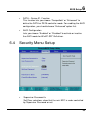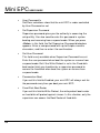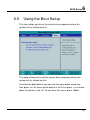
1
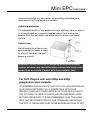
!
Mini EPC
USER GUIDE
Copyright©2006
All Rights Reserved - Printed in Taiwan
Mini EPC User Guide
Original Issue: 2006/06
This manual guides you in setting up and using your new mini EPC.
Information in this manual has been carefully checked for accuracy
and is subject to change without notice.
No part of this manual may be reproduced, stored in a retrieval
system, or transmitted, in any form or by any means, electronic,
mechanical, photocopy, recording, or otherwise, without prior written
permission.
Trademarks
Product names used herein are for identification purposes only and
may be the trademarks of their respective companies.
Microsoft, Windows XP Professional, and Media Center Edition 2005
are trademarks of Microsoft Corporation.
TM
Intel ®, Intel ® Core Duo, and Intel ® HD Audio (Azalia) are
registered trademark of Intel Corporation.
All other brands or product names mentioned in this manual are
trademarks or registered trademarks of their respective companies.
2
Mini EPC
USER GUIDE
FCC Information to User
Safety and Care Instructions
No matter what your level of experience with mini EPC, please make
sure you read the safety and care instructions. This information can
help to protect you and your mini EPC from possible harm.
Radio and television interference
Warning: Use the specified shielded power cord and shielded signal
cables with this mini EPC, so as not to interfere with radio and
television reception. If you use other cables, it may cause interference
with radio and television reception.
This equipment has been tested and found to comply with the limits
for a Class B digital device, pursuant to Part 15 of the FCC Rules.
These limits are designed to provide reasonable protection against
harmful interference in a residential installation. This equipment
generates, uses and can radiate radio frequency energy and, if not
installed and used in accordance with the instructions, may cause
harmful interference to radio communications. However, there is no
guarantee that interference will not occur in a particular installation. If
this equipment does not cause harmful interference to radio or
television reception, which can be determined by turning the
equipment off and on, the user is encouraged to try to correct the
interference by one or more of the following measures:
•
Reorient or relocate the receiving antenna
•
Increase the separation between the device and receiver
•
Connect the device into an outlet on a circuit different from that
to which the receiver is connected.
3
Mini EPC
•
USER GUIDE
Consult the dealer or an experienced radio/television technician
for help.
You may find helpful the following booklet, prepared by the Federal
Communications Commission: Interference Handbook (stock number
004-000-00345-4). This booklet is available from the U.S.
Government Printing Office, Washington, DC20402
Warning: The user must not modify or change this mini EPC without
approval. Modification could void authority to this equipment.
FCC RF Exposure
FCC RF Radiation Exposure Statement:
This Transmitter must not be co-located or operating in conjunction
with any other antenna or transmitter.
This equipment complies with FCC RF radiation exposure limits set
forth for an uncontrolled environment. This equipment should be
installed and operated with a minimum distance of 20 centimeters
between the radiator and your body.
15.247 (b)(4), the EUT meets the requirement that it be operated in a
manner that ensures the public is not exposed to radio frequency
energy levels in excess of the Commission’s guidelines (1.1307,
1.1310, 2.1091 and 2.1093)
5.105 Federal Communications Commission (FCC)
Requirements, Part 15
This equipment has been tested and found to comply with the limits
for a class B digital device, pursuant to part 15 of the FCC Rules.
These limits are designed to provide reasonable protection against
harmful interference in a residential installation.
4
Mini EPC
USER GUIDE
This equipment generates, uses and can radiate radio frequency
energy and, if not installed and used in accordance with the
instructions, may cause harmful interference to radio
communications. However, there is no guarantee that interference will
not occur in a particular installation. If this equipment does cause
harmful interference to radio or television reception, which can be
determined by turning the equipment off and on, the user is
encouraged to try to correct the interference by one or more of the
following measures:
---Reorient or relocate the receiving antenna.
---Increase the separation between the equipment and receiver.
---Connect the equipment into an outlet on a circuit different from that
to which the receiver is connected.
---Consult the dealer or an experienced radio/TV technician for help.
5.21 Regulatory information / Disclaimers
Installation and use of this Wireless LAN device must be in strict
accordance with the instructions included in the user documentation
provided with the product. Any changes or modifications (including the
antennas) made to this device that are not expressly approved by the
manufacturer may void the user’s authority to operate the equipment.
The manufacturer is not responsible for any radio or television
interference caused by unauthorized modification of this device, or
the substitution of the connecting cables and equipment other than
manufacturer specified. It is the responsibility of the user to correct
any interference caused by such unauthorized modification,
substitution or attachment. Manufacturer and its authorized resellers
or distributors will assume no liability for any damage or violation of
5
Mini EPC
USER GUIDE
government regulations arising from failing to comply with these
guidelines.
IMPORTANT NOTE (CO-LOCATION)
FCC RF Radiation Exposure Statement: This equipment complies
with FCC RF radiation exposure limits set forth for an uncontrolled
environment. This device and its antenna must not be co-located or
operating in conjunction with any other antenna or transmitter.
IMPORTANT NOTE (CO-LOCATED EVALUATION PERFORMED)
This transmitter has been demonstrated co-located operation
compliance requirement with [PRODUCT
DESCRIPTION/BRAND/MODEL#]. This transmitter must not be colocated or operating in conjunction with any other antenna or
transmitter.
Radio Frequency Interference Requirements
This device is restricted to INDOOR USE due to its operation in the
5.15 to 5.25GHz frequency range. According to FCC 15.407(e),
requires this product to be used indoors for the frequency range 5.15
to 5.25GHz to reduce the potential for harmful interference to cochannel of the Mobile Satellite Systems.
High power radars are allocated as primary user of the 5.25 to
5.35GHz and 5.65 to 5.85GHz bands. These radar stations can cause
interference with and / or damage this device
Canadian Department of Communications
Compliance Statement
6
Mini EPC
USER GUIDE
This Class B digital apparatus meets all requirements of the
Canadian Interference-Causing Equipment Regulations.
Shielded Cables Notice
All connections to other computing devices must be made using
shielded cables to maintain compliance with FCC regulations.
Peripheral Devices Notice
Only peripherals (input/output devices, terminals, printers, etc)
certified to comply with Class B limits may be attached to this
equipment. Operation with non-certified peripherals is likely to result
in interference to radio and TV reception.
Optical Disk Drive Notice
The optical disk drive is Class 1 Laser Product.
Caution
Changes or modifications not expressly approved by the
manufacturer may void the user’s authority, which is granted by the
Federal Communications Commission, to operate this mini EPC.
Use Conditions
This part complies with Part 15 of the FCC Rules. Operation is
subject to the following conditions: (1) this device may not cause
harmful interference, and (2) this device must accept any interference
received, including interference that may cause undesired operation.
European Notice
For the following equipment: Mini EPC
7
Mini EPC
USER GUIDE
Is herewith confirmed to comply with the requirements set out in the
Council Directive on the Approximation of the Laws of the Member
States relating to Electromagnetic Compatibility (89/336/EEC), Low
voltage
Directive (73/23/EEC) and the Amendment Directive
(93/68/EEC), the procedures given in European Council Directive
99/5/EC and 89/3360EEC.
The equipment was passed. The test was performed according to the
following European standards:
EN 300 328 V.1.6.1 (2004)
EN 301 489-1 V.1.3.1 (2001) / EN 301 489-17 V.1.2.1 (2001)
EN 50371 (2002)
EN 60950 (2000)
EN 55022: 2001
EN 55024: 2001
EN 60950: 2000
EN 61000-3-2: 2000
EN 61000-3-3: 1995 + A1: 2001
802.11b & 802.11g Restrictions:
8
Mini EPC
USER GUIDE
- European standards dictate maximum radiated transmit power of
100mW EIRP
and frequency range 2.400-2.4835GHz;
- In France, the equipment must be restricted to the 2.44652.4835GHz
frequency range and must be restricted to indoor use."
Regulatory statement (R&TTE / WLAN IEEE 802.11a)
Operation of this device is subjected to the following National
regulations and may be prohibited to use if certain restriction should
be applied.
51505350MHz
Austria
Limited to 5150 – 5250 MHz
Belgium
5250 - 5350 MHz excluded
Croatia
Licence required
Italy
General authorization required if used
outside own premises
Latvia
Limited to 5150 – 5300 MHz, Under
Study
Luxembourg None; General authorization required for
public service
54705725MHz
Austria
Not implemented; Military band
Bulgaria
Not implemented
Croatia
Not implemented
Czech
Republic
Not implemented; Planned
9
Mini EPC
USER GUIDE
France
Not implemented; France will implement
this band identified by the ERC
DEC(99)23 when the efficiency of the
mitigation techniques made mandatory by
this Decision is ensured
Hungary
Not implemented; Equipment/ Standard
not available
Italy
General authorization required if used
outside own premises
Luxembourg None; General authorization required for
public service
Slovak
Republic
Not implemented; Military services
Television antenna connectors protection (for system
TV tuner card)
External television antenna grounding
If an outside antenna or cable system is to be connected to your mini
EPC, make sure that the antenna or cable system is electrically
grounded to provide some protection against voltage surges and static
charges.
ANSI/NFPA 70, the National Electrical Code (NEC), in particular
Section 820.93, provide information with regard to proper grounding of
the mask and supporting structure, grounding of the lead-in wire to an
antenna discharge unit, size of grounding conductors, location of
10
Mini EPC
USER GUIDE
antenna discharge unit, connection to grounding electrodes, and
requirements for the grounding electrode.
Lightning protection
For added protection of any product during a lightning storm or when it
is left unattended or unused for long periods of time, unplug the
product from the wall outlet and disconnect the antenna or cable
system.
Power Lines
Do not locate the antenna near
overhead light or power circuits,
or where it could fall into such
power or circuits.
WARNING: When installing or realigning an outside antenna
system, extreme care should be taken to keep from touch such
power lines or circuits. Contact with them could be fatal.
For DVD Players with both 525p and 625p
progressive scan outputs:
‘CONSUMERS SHOULD NOTE THAT NOT ALL HIGH DEFINITION
TELEVISION SETS ARE FULLY COMPATIBLE WITH THIS
PRODUCT AND MAY CAUSE ARTIFACTS TO BE DISPLAYED IN
THE PICTURE. IN CASE OF 525 OR 625 PROGRESSIVE SCAN
PICTURE PROBLEMS, IT IS RECOMMENDED THAT THE USER
SWITCH THE CONNECTION TO THE ‘STANDARD DEFINITION’
OUTPUT. IF THERE ARE QUESTIONS REGARDING OUR TV SET
11
Mini EPC
USER GUIDE
COMPATIBILITY WITH THIS MODEL 525p AND 625p DVD
PLAYER, PLEASE CONTACT OUR CUSTOMER SERVICE
CENTER.’
“This product incorporates copyright protection technology that is
protected by U.S. patents and other intellectual property rights. Use of
this copyright protection technology must be authorized by
Macrovision, and is intended for home and other limited viewing uses
only unless otherwise authorized by Macrovision. Reverse
engineering or disassembly is prohibited.”
“U.S. Patent Nos. 4,631,603; 4,819,098; 4,907,093; 5,315,448; and
6,516,132.”
12
Mini EPC
USER GUIDE
Contents
1
INTRODUCTION .............................................................................. 15
1.1
1.2
1.3
1.4
1.5
2
GETTING STARTED ....................................................................... 25
2.1
2.2
2.3
2.4
3
USING MEDIA CENTER REMOTE CONTROL .................................. 33
USING W IRELESS USB KEYBOARD (OPTION).............................. 36
CONFIGURING YOUR SCREEN DISPLAY ....................................... 38
HOW TO ACCESS THE OPTICAL DRIVE......................................... 38
USING FLASH MEMORY CARDS .................................................... 40
MICROSOFT MEDIA CENTER......................................................... 43
4.1
4.2
4.3
5
CONNECTING THE AC POWER SOURCE ...................................... 25
CONNECT YOUR MINI EPC TO A TV ............................................. 26
Attach the Antenna to your mini EPC..................................... 27
Connect a TV with the S-Video connection........................... 28
CONNECT MINI EPC TO A PC MONITOR ...................................... 30
INSTALLING THE MINI EPC DEVICE DRIVERS ............................... 31
driver installation note: .............................................................. 31
USING YOUR MINI EPC................................................................. 33
3.1
3.2
3.3
3.4
3.5
4
FEATURE HIGHLIGHT .................................................................... 15
UNPACKING THE MINI EPC ........................................................... 18
THE FRONT SIDE OF THE MINI EPC ............................................. 19
THE REAR SIDE OF THE MINI EPC .............................................. 20
MEMORY UPGRADE ...................................................................... 23
W HAT IS W INDOWS XP MEDIA CENTER EDITION 2005? ........... 43
STARTING THE WINDOWS XP MEDIA CENTER FOR THE FIRST TIME. 44
ENJOY YOUR MEDIA CENTER....................................................... 51
CONNECTING TO PERIPHERALS.............................................. 57
13
Mini EPC
5.1
5.2
5.3
5.4
5.5
USER GUIDE
USING THE USB PORT ................................................................. 57
USING THE LAN PORT ................................................................. 58
USING THE IEEE 1394 PORT ...................................................... 58
USING THE W IRELESS LAN ......................................................... 59
USING THE MODEM PORT ............................................................ 60
BIOS SETUP .................................................................................... 61
6
6.1
6.2
6.3
6.4
6.5
6.6
RUNNING THE BIOS SETUP PROGRAM ....................................... 61
USING THE MAIN MENU SETUP .................................................... 62
USING THE ADVANCED CMOS SETUP ........................................ 64
SECURITY MENU SETUP............................................................... 65
USING THE BOOT SETUP .............................................................. 67
HOW TO EXIT THE SETUP PROGRAM ........................................... 68
CARING FOR YOUR MINI EPC.................................................... 71
7
IMPORTANT SAFETY INSTRUCTIONS ....................................................... 71
ENVIRONMENT ........................................................................................ 71
POWER SUPPLY ..................................................................................... 72
CLEANING YOUR MINI EPC ................................................................... 73
MAINTAINING HARD DISK ....................................................................... 73
APPENDIX A
SYSTEM SPECIFICATIONS ................................. 75
SYSTEM SPECIFICATIONS ....................................................................... 76
APPENDIX B NOTICE FOR WINXP MCE INSTALLATION........... 79
How to install WinXP MCE (Media Center Edition) with AHCI driver ?. 80
How to install WinXP MCE (Media Center Edition) without AHCI driver ?82
14
Introduction
1
1 Introduction
TM
With an Intel® Viiv technology-based PC and supporting devices,
you can enjoy a growing universe of digital media content and explore
endless entertainment options from the comfort of your couch.
With mini EPC, every member of your family can enjoy the immersive
experience of PC games and movies on a big screen. Users can
interact with an entertainment PC with an USB mouse and keyboard,
or with an optional remote control, which provides an exciting viewing
experience from the comfort of the living room sofa.
1.1
Feature Highlight
Before we go to identify each part of your mini EPC, we will first
introduce you to other notable features of your mini EPC.
TM
Intel® Viiv technology is Intel’s new platform designed for the
enjoyment of digital entertainment. It delivers the multitasking power
of a dual-core processor and enables sleek new designs that fit your
lifestyle. Besides, Microsoft XP Media Center Edition 2005 extends
the experience you have ever had. With a full range of powerful, yet
easy-to-use digital entertainment features, you can experience TV,
DVD movies, music and photos like never before.
15
Mini EPC
USER GUIDE
Processing Unit
TM
•
Your mini EPC runs on Intel ® Core Duo microprocessor that is
integrated with 2MB L2 Cache. Check with your dealer on the
CPU type and speed.
•
Fully compatible with an entire library of PC software based on
operating systems such as Windows XP Window Media Center
Edition 2005.
Operating System for Windows XP Media Center Edition
2005
Microsoft XP Media Center Edition 2005 extends the experience you
have. With a full range of powerful, yet easy-to-use digital
entertainment features, you can experience TV, DVD movies, music
and photos like never before.
Wireless LAN
Intel PRO/Wireless 3945ABG Network Connection
(IEEE 802.11 a/b/g, Tri-mode)
Memory
This mini EPC provides two memory slots for installing DDR2 SDRAM
200-pin SODIMM modules up to 2GB using 256MB, 512MB, or
1024MB DDR2 SDRAM modules.
USB 2.0
Provides four USB ports (one at front side and three at rear side) for
fastest I/O data transmission.
16
Introduction
1
Graphic System
Provides blazing graphics controller embedded in Intel® 945GM
chipset
Audio System
Azalia ACL260 sound codec chip; compliant with Intel HD Audio.
Bluetooth 2.0 (Class 2)
Bluetooth 2.0 is backward compatible with 1.x, and its EDR
(Enhanced Data Rate) is 2.1 Mbit/s. It offers a wireless connection
radius of 32.8 feet (10 meters) to other Bluetooth devices.
17
Mini EPC
1.2
USER GUIDE
Unpacking the mini EPC
Your mini EPC comes securely packaged in a sturdy cardboard
shipping carton. Upon receiving your mini EPC, open the carton and
carefully remove the contents. The shipping carton contains the
following items:
Mini EPC
Remote Control
(optional)
Antenna ( opcional )
DVI-VGA Adapter
(optional)
AC Adapter and Power Cord
Wireless USB Keyboard
(optional)
User Manual or Manual / Drivers CD (optional)
18
Introduction
1
Carefully inspect each component to make sure that nothing is
missing and/or damaged. If any of these items is missing or
damaged, notify your dealer immediately. Be sure to save the
shipping materials and the carton in case you need to ship the mini
EPC or if you plan to store the mini EPC away sometime in the future.
1.3
The Front Side of the mini EPC
1. Eject Button
2. 4-in-1 Card Reader
3. USB Port
4. Optical Disk Drive
5. Power On/Resume Button
Feature
Description
1. Eject Button
Press this button to eject optical disk.
2. 4-in-1 Card
Reader
The card slot supports SD, MMC, MS (Memory
Stick) and MS_Pro flash memory card format.
You can use any of the 4 types flash memory
19
Mini EPC
USER GUIDE
Feature
Description
cards for extra storage media.
1.4
3. USB Port
The Universal Serial Bus (USB) port allows
you to connect up to USB-equipped peripheral
devices (for example, USB mouse, digital
camera, USB storage device and so on).
4. Optical Disk
Drive
This optical disk drive is Slot-in type ODD. It
allows you to load and start programs from a
CD/DVD and play DVD movies and audio
CDs. It also can burn CD/DVD.
5. Power On
/Resume
Button
Switches the mini EPC power on or off, or
resumes whenever it is in Suspend mode.
The Rear Side of the Mini EPC
The system ports at the back of your mini EPC can connect various
devices. Each port is described as followings.
20
Introduction
1. IEEE 1394
3. TV_IN
5. Microphone Jack
7. DVI-I Socket
9. TV Port (S-video)
11. USB Port
Feature
1
2. Modem Port
4. AV_In Port
6 Headphone Jack
8. LAN Port
10 USB Ports
12. DC_In
Description
1. IEEE 1394
IEEE 1394 port is a high speed I/O port that
can transfer high levels of data in real-time,
such as Digital Video Camera, external hard
disk.
2. Modem Port
A 56K internal fax/data modem is built-in. It
keeps you connected to the outside networks
through telephone line.
3. TV_IN
Connects to an antenna to receive television
21
Mini EPC
USER GUIDE
Feature
Description
signal for watching and recording TV programs.
4. AV_In Port
This port is for Audio and Video input.
5. Microphone
Jack
Allows you to connect an external microphone.
6 Headphone
Jack
Lets you plug in high-definition headphone,
powered speakers, or earphone. (The SPDIF
transmits digitized audio signal by optical fiber.
The external audio amplifier can get the best
audio quality without loss.)
7. DVI-I Socket
This socket can accept both analog signal
(VGA) and digital signal (DVI) inputs.
The “DVI-I” is the abbreviation of “Digital Video
Interactive-Integrated”.
8. LAN Port
An internal 10/100/1000Base-T Gigabit
Ethernet LAN module connects your mini EPC
to other mini EPCs/networks through a local
area network (LAN).
9. TV Port (Svideo)
Lets you connect to the S-Video TV connector
for watching TV programs or DVD movie.
10. 11. USB Ports The Universal Serial Bus (USB) port allows you
to connect up to USB-equipped peripheral
devices (for example, USB mouse, digital
camera, USB storage device and so on).
12. DC_In
22
Lets you connect the AC power adapter in
supplying continuous power to your mini EPC.
Introduction
1.5
1
Memory Upgrade
Your mini EPC offers 200-pin SODIMM (Small Outline Dual Inline
Memory Module) at least 256MB DDR2-SDRAM. The memory
compartment is located inside your mini EPC. The table below lists
the possible combinations of different memory module and memory
size.
☞
Please contact dealer for changing or adding DDR2-SDRAM
module. It is not available for users to change it by themselves.
Based Memory
Installing Memory
Total
256 MB
0 MB
256 MB
256 MB
256 MB
512 MB
256 MB
512 MB
768 MB
256 MB
1024MB
1280MB
512 MB
0 MB
512 MB
512 MB
256 MB
768 MB
512 MB
512 MB
1024 MB
512 MB
1024MB
1536MB
1024 MB
0 MB
1024 MB
1024 MB
256 MB
1280 MB
1024 MB
512 MB
1536 MB
1024 MB
1024 MB
2048 MB
23
Mini EPC
USER GUIDE
This page is intended to be blank.
24
Getting Started
2
2
Getting Started
Your mini EPC is designed and pre-configured for easy setup and use.
This chapter describes the installation steps you should follow to get
the mini EPC up and running as quickly as possible. Contact your
dealer if they have pre-installed all the needed drivers to fully operate
your mini EPC or if there is the updation on the driver installation of the
mini EPC.
2.1
Connecting the AC Power Source
The AC adapter provides external power source to your mini EPC and
the AC adapter also has an auto-switching design that can connect to
any 100VAC ~ 240VAC power outlets.
To connect the power adapter:
1. Plug the AC power cord into the power socket of the AC power
adapter. And plug the other end of the AC power cord to a live AC
wall outlet.
25
Mini EPC
USER GUIDE
2. Plug the connector of the AC adapter to the DC-IN port found at
the rear side of the mini EPC.
☞
For the power supply of this equipment, an approved power
cord has to be used.
Make sure the socket and any extension cord(s) you use can
support the total current load of all the connected devices.
Before cleaning the mini EPC, make sure it is disconnected
from any external power supplies (i.e. AC adapter).
2.2
Connect your mini EPC to a TV
Connect your mini EPC (running Microsoft Windows XP Media Center
Edition 2005) to your TV, and you can enjoy your favorite mini EPC
and TV entertainment from the same spot in your living room. You
can enjoy live and recorded TV, DVDs, music, photos, and Online
26
Getting Started
2
Spotlight'
s offerings on the big screen from the comfort of your
couch — and you can control it all with a single remote control.
Attach the Antenna to your mini EPC
The mini EPC has built-in a TV tuner card to process analog
television signals. (Beside, this TV tuners card functions as video
capture cards to record television programs onto a hard disk.)
TV tuners supporting digital television broadcasts have recently
become available; a tuner displaying an HDTV image on a mini EPC
monitor is typically much cheaper than a dedicated high-definition
television system. The TV tuner card also supports time-shifting
capabilities, allowing the viewer to rewind, fast-forward and pauses
live TV.
The mini EPC also comes with an Antenna. To receive television
signal well, you need to attach the antenna to your mini EPC.
27
Mini EPC
USER GUIDE
Connect a TV with the S-Video connection
1. Connect the S-Video cable to your TV Port, located on the back
of your Media Center PC.
28
Getting Started
2
2. Connect the other end of the S-Video cable to the S-Video input
connection on the back of your TV.
Enjoy your digital Lifestyle
29
Mini EPC
2.3
USER GUIDE
Connect mini EPC to a PC Monitor
You can connect a monitor to your PC mini EPC with running
Microsoft Windows XP Media Center Edition 2005. All you have to do
is plug the cable from the monitor into the back of the high-level mini
EPC with a DVI-I Socket.
Most monitors use a VGA cable to connect to a PC. In this case, you
can connect the VGA cable from the monitor to the DVI-I Socket on
the back of your Media Center PC via a DVI-VGA Adapter. Or you
can connect directly to the monitor with DVI socket.
30
Getting Started
2.4
2
Installing the mini EPC Device Drivers
It is best to install the needed device drivers for using the built-in
devices of your mini EPC. Before installing the drivers, check with
your dealer first if they have already installed all the drivers along with
the operating system. If not, follow the procedures below:
DRIVER INSTALLATION NOTE:
NOTE: Please be notified that whenever you install the driver
utility, it should be install the CHIPSET Driver first.
Installing Drivers for Media Center Edition (MCE)
1. From the Windows toolbar, click the Start button, then point to
Run. The Run dialog box appears.
2. Click the Browse button and specify the directory as where the
device driver is located.
3. Read the on-screen information, and follow the on-screen
instructions to complete drivers installation.
Device Driver
Driver Path
Chipset device
"E:\Drivers\MCE\Chipset\ Infinst_auto.exe "
VGA device
"E:\Drivers\MCE\VGA\Setup.exe"
Audio device
31
Mini EPC
USER GUIDE
"E:\Drivers\MCE\Audio\Setup.exe"
Modem driver
"E:\Drivers\MCE\Modem\ssetup.exe"
Wireless LAN driver and Utility
“E:\Drivers\MCE\Wireless LAN\Autorun.exe”
LAN driver
"E:\Drivers\MCE\LAN\Autorun.exe"
Card Reader driver
"E:\Drivers\MCE\Card Reader\setup.exe"
East Fork driver
"E:\Drivers\MCE\East Fork\setup.exe"
TV Tuner driver
"E:\Drivers\MCE\TV Tuner\M103_WHQL_Drv_
BDA_x32_V3.5.0.16.exe"
TV Tuner software encoder
"E:\Drivers\MCE\TV Tuner\installfilter.exe"
Matrix Storage software utility
"E:\Drivers\MCE\Matrix Storage\Setup.exe"
Viiv software
"E:\Drivers\MCE\ViiV Software\Setup.exe"
USB Wake up driver
"E:\Drivers\MCE\USBWakeup01a\Setup.exe"
32
Using Your Mini EPC
3
3
Using Your Mini EPC
This chapter describes how to operate the standard features of the
mini EPC. With mini EPC, every member of your family can enjoy the
immersive experience of PC games and movies on a big screen.
Users can interact with an entertainment PC with an USB mouse and
keyboard, or with an optional remote control, which provides an
exciting viewing experience from the comfort of the living room sofa.
3.1 Using Media Center Remote Control
The mini EPC comes with a Media Center remote control, and this
Media Center remote control bring your Media Center experience to a
whole new level.
33
Mini EPC
USER GUIDE
Media Center Remote Control
Button
Description
Press the RECORD button on the remote to
begin recording what you’re currently watching.
To find and watch it later, simply press the
RECORD TV button.
The MORE INFO button brings up additional
option related to where you are in the menu
system. You can also press MORE INFO to get
details on the music, TV, pictures, or video that is
selected.
34
Using Your Mini EPC
Button
3
Description
When navigating through the Media Center menu
system, press the BACK button to go to the
previous screen.
Use the CURSOR ARROWS to navigate up,
down, left, or right through the Media menu
system. When you find what you want, press OK
button in the center of the arrows to select it.
The GREEN START BUTTON will launch the
Media Center menu system when you are in
Windows XP. If you are navigating around the
Media Center, press GREEN START BUTTON
will bring you back to the Media Center Starting
menu options.
Press SKIP on the remote to jump forward in 30
seconds time increments in the recorded TV
show you’re watching. If you want to see that
great sports play again when watching live TV or
recorded TV, press REPLAY on the remote and
watch it again.
Press RECORD TV to go directly to the
Recorded TV menu and see what recorded TV
programs you have saved on the mini EPC.
Press the GUIDE button to go directly to the TV
program listings and find a show to watch now or
to select a show or series to record in the future.
Press the LIVE TV button to bring up TV on the
screen of the television connected to your mini
EPC.
35
Mini EPC
USER GUIDE
Button
Description
Press the DVD MENU button to access the main
menu of the DVD in your DVD drive and to begin
watching it.
Use the NUMBER KEYS to go directly to the TV
channel you want to watch or use them to type
letters, numbers, or symbols into a search box.
3.2
Using Wireless USB Keyboard
(option)
Before using the wireless USB keyboard, you must activate
communication between the mini EPC and the wireless USB
Keyboard.
Please follow the steps to install the wireless USB keyboard.
1. Turn the keyboard upside down to open the battery compartment
which is located on the bottom of the keyboard.
2. Insert supplied batteries and replace battery compartment cover.
3. Connect USB Receiver to the USB port at the min EPC.
4. Press the button on the USB Receiver, then press “ID Link”
button on the keyboard within 10 seconds to communicate
signals.
36
Using Your Mini EPC
3
Key numbers: 99Keys (including hot-keys)
with Track Ball (mouse) function
37
Mini EPC
USER GUIDE
Battery: AA size Battery x4
Parameters for Remote Control
Distance for remote control: within 5m.
Angle for remote control: 360 degrees
Frequency for signal transmitted: at 2.4GHz frequency.
Standby Mode: System will wait for 5 minutes to activate Standby
Mode if there is no any input signal. You can touch any key to resume
system. During Standby Mode, mouse (pointing device) will be
disabled while keyboard function reminds alive.
3.3
Configuring Your Screen Display
Possible Display Configurations
The table below shows you the possible display resolution you can set
when using either the LCD display or the external monitor (CRT):
Display
Maximum Resolution
Maximum Colors
External Monitor
1600x1200, 85Hz
32-bit true colors
☞
65,536 or 64K colors is also equivalent to 16-bit high color while 16
million or 16M colors is equivalent to 32-bit true color.
3.4
How to Access the Optical Drive
Your mini EPC is equipped with a Slot-in type DVD multi/Combo drive
on the front panel of the mini system. You can play music from audio
38
Using Your Mini EPC
3
CDs or play DVD movies. You can also burn music CDs, and save
documents and other digital files on CD-R/DVD-R or CD-RW/DVDRW discs.
To insert and remove an optical disk on the drive:
1. Make sure the mini EPC is turned on.
2. Slide the optical disk into the slot-in type optical drive with the
label side facing up.
☞
Some DVD are two-sided and don’t have a label on the either side.
3. To remove the optical disc. Be sure close CD/DVD player related
programs.
4. Press the eject button under the optical drive slot. Then the
optical disc will slide out.
39
Mini EPC
USER GUIDE
How to care the CD/DVD
When you handle CDs, pay attention to the following guidelines:
3.5
•
Always pick up the CD by its edges.
•
Avoid scratching or soiling either side of the CD.
•
Do not write with the hard ball-point pen or apply labels on either
side of the CD.
•
Keep the CD away from direct sunlight or high temperatures.
•
Clean fingerprints or dust from the CD by wiping it with a soft
cloth.
Using Flash Memory Cards
What is Flash Memory Card?
Flash Memory is a memory storage media. They are used by most
digital camera, mobile phone, and PDA. Flash memory cards are built
with different form factor and brand name. Their sizes are smaller
than PCMCIA card. The 4 in 1 card slot of this mini EPC supports the
40
Using Your Mini EPC
3
flash memory card as SD, MMC, MS (Memory Stick), and MS_Pro
cards.
☞
For a single moment, only one card can be inserted into the 4 in 1
card slot.
To insert and remove a Flash Memory Card:
For MMC and SD card, you should position the copper connector at
the bottom side. For Memory Stick card, you should position the
copper connector at the topside. All of these cards should be located
at the center of the slot in inserting.
Slot
Card type
Copper connector
4 in 1
SD (Secure Digital)
MMC (MultiMedia Card)
MS (Memory Stick)
MS_Pro
Bottom side
Bottom side
Top side
Top side
Only one correct side can be accepted for the 4 in 1 card slot. If you
cannot insert the card into the 4 in 1 slot or you had inserted the card
but it is not recognized by the mini EPC, please remove the card and
turn the card upside down and insert it again. To prevent the damage
made both on card and the slot, never force an entry into the slot with
incorrect side.
41
Mini EPC
USER GUIDE
To remove the flash memory card, you should first disable the card
setting at the taskbar of the windows XP. Then, you only pull out the
card by fingers; there is no release button for flash memory slot.
42
Microsoft Media Center
4
4
Microsoft Media Center
The Mini Entertainment PC integrated in a highly compact platform is
designed for digital entertainment. That means you can take charge
of your media, share moves, TV, photos, and music with your friends
and family. It simplifies our digital life.
At the heart of a Media Center PC is a powerful Windows XP-base
mini EPC so you can send e-mail, browse the web, and get your work
done.
4.1
What is Windows XP Media Center
Edition 2005?
Windows XP Media Center Edition 2005 is an operating system that
enables you to enjoy the best in home entertainment on your mini
EPC. With Media Center Edition 2005, you can store, share and
enjoy all of your photos, all of your music, all of your home video and
even recorded TV. It’s all contained in one control system. That’s as
easy to use as a normal television set, combining all-in-one access
from a single remote control with a great new user-friendly interface.
Windows XP Media Center Edition 2005 is built on the foundations of
Windows XP Professional Edition, it’s still a full-functional PC you can
use with your usual word-processing, e-mail sending and other
programs.
43
Mini EPC
4.2
USER GUIDE
Starting the Windows XP Media
Center for the First Time
Once you have set up your mini EPC and have connected it with the
necessary hardware devices, you are ready to set up your Media
Center for the first time.
1.
Click the Start button, then select Media Center, or you can
press the Green Start Button on the Media Center Remote
Control to launch Media Center.
The first time you start Media Center, the screen of
“Welcome… Setup Wizard” appears.
NOTE: The Media Center setup wizard requires an Internet
connection to complete the process.
44
Microsoft Media Center
2.
4
Press the NEXT button to continue.
Read the on-screen information and select your option, then
system will automatically configure your setting. And, you will
find Media Center has made system configurations easily.
3.
Now you can begin to select your option item “1 Required
Setup” on the screen and set up your TV signal, then press
NEXT to continue.
45
Mini EPC
4.
46
USER GUIDE
This screen informs you Media Center Privacy Policy. Read and
accept it. Press NEXT to continue.
Microsoft Media Center
5.
4
This screen lets you connect to a variety of multimedia
information. Select Yes and press Next to continue.
Follow the on-screen instructions to select your option and
complete the setting of Join Wireless Network and Internet
Connection. The system will detect the signal and finish most
of the setup for you. If not, follow the on-screen instructions.
You can also use the arrow keys on your remote control to
move the Yes or No option. Press OK button to select the
option, Select Next to continue.
6.
This screen allows you to test your Internet Connection. Select
Test. When the test is finished. Press Next to continue.
47
Mini EPC
48
USER GUIDE
7.
This screen allows you customize your Media Center. When you
finished your settings. Select I am finished and press Next.
8.
This is final screen of Media Center Setup Wizard. Press Finish
button to complete Media Center Setup and start Media Center.
Microsoft Media Center
9.
4
Now here comes the Windows XP Media Center Edition 2005.
To enjoy the full benefit of Media Center, you can always go to
the screen as listed below to change the setting.
To change the setting, please select the option item by item as
shown on the screen, then it will appears Settings option. You
can set the parameters with Settings option any time.
49
Mini EPC
50
USER GUIDE
Microsoft Media Center
4.3
4
Enjoy Your Media Center
Media Center extends the experience you have ever had. With a full
range of powerful, yet easy-to-use digital entertainment features, you
can experience TV, DVD movies, music and photos like never before.
It’s a whole new way to enjoy your digital entertainment.
Take your time and get familiar with the basics behind the Media
Center menu system and using a remote control with your mini EPC.
To use a remote control, push the Green Button.
51
Mini EPC
USER GUIDE
Easily view your pictures
With Microsoft Windows XP Media Center Edition 2005, you can
display slide shows of your digital pictures anytime.
Watch DVDs
Enjoy watching DVDs with Microsoft Windows XP Media Center
Edition 2005. Just put the DVD in your system'
s optical drive, and
then use your remote control to start it.
Enjoy music
With Microsoft Windows XP Media Center Edition 2005, it'
s easy to
access your entire music library. You can use Media Center to play
individual songs or entire albums, view album covers, play songs by
genre, create playlists of your favorite songs, and watch captivating
visualizations that change with the rhythm of your music.
First, build your music library by copying music from CDs or by
adding digital music on your PC to your library. Then, you can
use Media Center to listen to your music.
Here are three examples of operation of Media Center from
Microsoft’s website.
To watch a DVD
52
Microsoft Media Center
4
This mini EPC provides the enjoyment for watching DVDs with
Microsoft Windows XP Media Center Edition 2005. You can use
optical drive to watch your favorite DVDs.
1. Slot in a DVD into the DVD drive.
2. Press the Green Start Button on your remote control to open the
Media Center Start menu.
3. Select Play DVD.
4. Use the relative buttons on your remote control to navigate the
DVD menu.
You can return to the DVD menu at any time by pressing the DVD
menu button on your remote control.
It is suggested you to use the Play DVD Screen
Record your favorite TV shows
You can record TV shows with Microsoft Windows XP Media Center
Edition 2005.
Record it now
If you are watching live TV and want to record what you are currently
watching, press the RECORD button on your remote control.
Record it later
To record a scheduled show using your remote control:
1. Press the Green Start Button on your remote control to open the
Media Center Start menu.
2. Select My TV..
53
Mini EPC
USER GUIDE
3. On the My TV page, select Guide
4. In the Guide, find the TV show you want to record. Highlight the
title of the show, and press the RECORD button on your remote
control. Press once to record the show; press a second time to
record the series. You'
ll notice the red icon displayed next to the
show title, which confirms that your selection has been scheduled
to record.
Recording TV shows is easy and fun with Media Center.
Burn your TV programs and movies onto DVDs
With Microsoft Windows XP Media Center Edition 2005, you can burn
TV shows or movies onto DVDs that you can play in standard DVD
players. After your burn your movies onto DVDs, you can delete them
from your Media Center PC to create space so that you can record
more TV and movies.
To burn a TV show or a movie to a DVD that you can watch
elsewhere:
1. Insert a writable DVD disk into your Media Center DVD drive.
2. Press the Green Start Button on your remote to open the Media
Center Start menu, and then select My TV.
3. On the My TV page, select Recorded TV.
4. On the Recorded TV page, select the show or movie that you
want to burn to a DVD, and then press the MORE INFO button on
your remote.
5. In the list of options that is displayed, select Create CD/DVD.
54
Microsoft Media Center
4
6. On the Disc Format page, select Video DVD, and then select OK.
Note: If the Video DVD option is not displayed on the Disc
Format page, the DVD burning software is not installed or is not
working correctly. Contact your hardware manufacturer for
assistance.
7. On the Name This DVD page, enter a name for your DVD if you
want to change the default setting. For example, to enter the
letter “a,” press 2 once. To enter the letter “b,” press 2 twice. An
index of all letters is displayed on the screen. Then select OK.
8. On the View DVD page, select Create DVD.
9. In the Initiating Copy dialog box, select Yes.
10. If the Fit Content to CD/DVD dialog box is displayed, select Yes.
The DVD may take several hours to create because Media
Center needs to compress the movie to fit on the DVD.
Note: When you select Yes in the Fit Content to CD/DVD dialog
box, the file is compressed so that the show fits on the disc, and
the file will play back with reduced image detail.
11. You can wait for the DVD to finish writing, or select OK in the
Creation Progress dialog box to continue using your mini EPC.
12. After Media Center creates your DVD, it automatically ejects the
DVD. Remove the DVD from the tray, and then close the tray.
13. When the Completing Disc Creation dialog box is displayed,
select Done.
For more information, please refer to Microsoft’s website:
http://www.microsoft.com/windowsxp/mediacenter/using/getstarte
d/default.mspx
55
Mini EPC
USER GUIDE
Windows Media Center is designed of Graphical User Interface and
very easy to use when you follow the on-screen instructions.
However, when you need additional information, Media Center
provides you with four domains (Help, Forum, Tips, and Hardware)
of assistance.
You can visit and browse each domain to experience the information
and assistance that Media Center offers.
56
Connecting to Peripherals
5
5
Connecting to Peripherals
This chapter describes how you attach peripheral devices to your mini
EPC. You can attach a printer or mouse; connect an external monitor
and keyboard, or any other peripheral device.
5.1
Using the USB Port
USB (Universal Serial Bus) is a hardware interface that enables you
to connect multiple devices (such as mouse, keyboard, storage
device, joystick, digital camera, and video conference cameras, etc.)
to your mini EPC. Besides, USB’s hot swap capability allows
everything to be plugged in and unplugged without turning the system
off.
Microsoft, HP, Compaq, Intel, Agere, NEC and Philip are seven core
members of USB-IF to have worked on USB 2.0 standardization.
USB 2.0 offers data transfer rate up to 480Mbps (megabits per
second) compared to USB 1.1 devices, which transfer at speeds of
12Mbps. So, you could know that USB 2.0 can transfer data between
the mini EPC and its peripherals 40 times faster than USB 1.1.
However, USB 2.0 is fully backward compatible, you will be able to
use a USB 1.1 device in a USB 2.0 compliant system.
57
Mini EPC
5.2
USER GUIDE
Using the LAN Port
This mini EPC is equipped with an internal 10B /100/1000Base-T
Gigabit Ethernet LAN module that connects your mini EPC to other
mini EPC/networks through a local area network (LAN) and supports
data transfer rates at 10/100Mbps and can be up to 1000Mbps. The
100Base-TX is called Fast Ethernet.
To meet higher bandwidth demand, this mini EPC has upgraded Fast
Ethernet to Gigabit Ethernet. The network becomes more efficient
while downloading movies, music or other multimedia files.
The built-in Gigabit Ethernet LAN module provides a standard RJ-45
connector.
5.3
Using the IEEE 1394 Port
IEEE 1394, also known as FireWire, is a high-bandwidth serial bus
developed by Apple and Texas Instruments. IEEE 1394 supports 100,
200, and 400 Mbps (Megabit per second) transfer rates and is widely
used for downing video from digital camcorders to the mini EPC. In
addition to its high speed, IEEE 1394 enables isochronous (real-time)
data transfer. This makes it ideal for devices that transfer highbandwidth of data in real-time, such as video devices. It supports both
Plug-and-Play and hot plugging, and also allows for the connection of
up to 63 devices.
With built-in IEEE 1394 port, this mini EPC enables the peripheral
devices in transmitting digital video data or data backup. The
Windows system will automatically recognize it after installing a
suitable driver for it. Please visit Microsoft'
s web site for more
58
Connecting to Peripherals
5
information about it. Moreover, you should install the driver of
peripheral device to connect with the IEEE 1394 port, for details
please refer to the manual that comes with your peripheral device.
5.4
Using the Wireless LAN
Access Point (AP) is the wireless transmission and receiving device, it
generally connects to the server of a LAN environment or act as a
LAN hub with wireless connection. Access point can be set in an
office environment, airport, major railway station, etc. that depends on
the construction of each country. In most case, you probably can use
it at office, please consult with the network department of your
company for more details.
This mini EPC integrates built-in Tri-mode 802.11 a/b/g wireless LAN
module with using Intel ® PRO/Wireless network solution by Intel ®
Centrino™ mobile technology. IEEE 802.11b standard supports 11
Mbps wireless connection speed. However, IEEE 802.11g supports
54Mbps wireless connection speed, and is backward compatible with
the slower 802.11b. Using the orthogonal FDM (ODFM) transmission
method, IEEE 802.11a operates in the 5 GHz frequency range and
provides up to 54 Mbps connection speed. The higher operating
frequency means a shorter transmission radius (about 60 feet). Yet,
802.11a offers more radio channels than 802.11b does. That can help
avoid radio and microwave interference.
Wireless LAN module is similar to LAN module. You need to install
software driver before using it. Please refer to chapter 2.5 on how to
install the driver.
59
Mini EPC
5.5
USER GUIDE
Using the Modem Port
This mini EPC comes equipped with a 56Kbps v.92 Data/Fax MDC
1.5 (Azalia) Modem that allows you to communicate with others via
fax, email, or to connect to an online service or bulletin board. The
built-in fax/data modem provides standard phone connector (RJ-11
connector).
NOTE: For electrical safety concerns, only use telephone
cables rated 26AWG or higher.
When using your telephone equipment, basic safety precautions
should always be followed to reduce the risk of fire, electric
shock and injury to persons, including the following:
1. Do not use this product near water, for example, near a bath
tub, wash bowl, kitchen sink or laundry tub, in a wet
basement or near a swimming pool.
2. Avoid using a telephone (other than a cordless type) during
an electrical storm. There may be a remote risk of electric
shock from lightning.
3. Do not use the telephone to report a gas leak in the vicinity
of the leak.
4. Use only the power cord and batteries indicated in this
manual. Do not dispose of batteries in a fire. They may
explode. Check with local codes for possible special
disposal instructions.
60
BIOS Setup
6
6
BIOS Setup
Your mini EPC also uses the Phoenix BIOS Setup program that allows
you to set several system configurations in changing the way your mini
EPC performs. This includes your system time and date, disk drive
configuration and password setup. This information is then stored in
the CMOS RAM and will remain permanent unless you change it
again.
6.1
Running the BIOS Setup Program
Your mini EPC is likely to have been properly setup and configured by
your dealer prior to delivery. However, you may find it necessary to
use the mini EPC’s BIOS (Basic Input-Output System) Setup program
to change system configuration information, such as your hard disk
drive type. The Setup program can be accessed when you power on
the system and pressing the <F2> function key.
As the POST (Power-On Self Test) executes during the boot up
process, the screen will display the following message:
Press <F2> to Enter SETUP
Press the <F2> key to run the BIOS Setup program. The BIOS Setup
program is organized into five menus which you can select using the
and
keys. To move from one option to another, you use the <+>
and <-> keys to change the settings. On the right hand side of the
61
Mini EPC
USER GUIDE
screen are some brief help descriptions of each item you want to
change.
To exit the BIOS Setup program, simply press the <Esc> key and
select from the Exit menu whether you want to save changes and
exit; discard changes and exit.
6.2
Using the Main Menu Setup
•
62
System Time
Allows you to change the system time using the hour: minute:
second format of the mini EPC.
You can also change the system time from your operating
system.
BIOS Setup
6
•
System Date
Allows you to set the system date using the month/date/year
format.
You can also change the system time from your operating
system.
•
IDE Channel 0 Master
This field displays various parameters for the hard disk drive. If
type [Auto] is selected, the system automatically sets these
parameters. If type [User] is selected, Cylinders, Heads and
Sectors and other value can be edited.
•
SATA Port 0
This field is for information only as the BIOS automatically detects
the optical drive.
•
CPU Type
This field reports the CPU type information detected by the BIOS
during Power-On Self-Test (POST).
•
CPU Speed
This field reports the CPU speed information detected by the
BIOS during Power-On Self-Test (POST).
•
System Memory
This field reports the amount of base (or conventional) memory
found by the BIOS during Power-On Self-Test (POST).
•
Extended Memory
This field reports the amount of extended memory found by the
BIOS during Power-On Self-Test (POST).
•
BIOS Version
This field is for information only as the BIOS displays the BIOS
version during the Power-On Self-Test (POST).
63
Mini EPC
6.3
64
USER GUIDE
Using the Advanced CMOS Setup
•
Legacy USB Support
Enable or disable the USB Bus support when in connection with
USB device.
•
Boot-time Diagnostic Screen
Lets you display or not display the diagnostic screen by choosing
Disabled or Enabled.
•
Extended Memory Testing
Determines which type of tests will be performed on extended
memory (above 1M).
BIOS Setup
6.4
6
•
SATA – Device 31, Function
This function lets you choose “Compatible” or “Enhanced” to
define the SATA or PATA controller mode. For enabling the AHCI
configuration, you should choose “Enhanced” option first.
•
AHCI Configuration
Lets you choose “Enabled” or “Disabled” to activate or inactive
the AHCI mode for WinXP-SPI* IAA driver.
Security Menu Setup
•
Supervisor Password Is
Set/Clear selections show that the mini EPC is under controlled
by Supervisor Password or not.
65
Mini EPC
66
USER GUIDE
•
User Password Is
Set/Clear selections show that the mini EPC is under controlled
by User Password or not.
•
Set Supervisor Password
Supervisor password gives you the authority in accessing the
setup utility. You also need to enter this password in system
booting and resuming from suspend mode. When you press
<Enter> in this field, the Set Supervisor Password dialog box
appears. Enter a new password with up to 8 alpha-numeric
characters, and then re-enter it for confirmation.
•
Set User Password
This field is only available when Supervisor Password has set.
Enter the user password when boot the system or resume from
suspend mode. But if the Write Protect is set in the Fixed disk
boot sector field, you should enter a supervisor password to
access the fixed disk when boot the system or resume from
suspend mode.
•
Password on Boot
If you set this field to Enabled, your mini EPC will always ask for
the password every time you boot your mini EPC.
•
Fixed Disk Boot Sector
If you set this field to Write Protect, the write protect boot sector
on hard disk will protect against viruses. In this situation, only the
supervisor can access the Boot Sector of fixed disk.
BIOS Setup
6.5
6
Using the Boot Setup
This item allows you to set the search drive sequence where the
system will try to boot up first.
This page allows you to set the search drive sequence where the
system will try to boot up first.
To select the boot device, you can use the up or down arrow key,
then press <+> to move up the device in the list or press <-> to move
down the device in the list. To exit from this menu, press <Esc>.
67
Mini EPC
6.6
USER GUIDE
How to Exit the Setup Program
There are two choices to escape from the Setup program.
68
•
Exit Saving Changes
Saves all changes to CMOS while running the BIOS setup
program and exit from the system setup program.
•
Exit Discarding Changes
Allows you to discard all changes made while running the BIOS
setup program and exit from the system setup program.
•
Load Setup Defaults
Lets you load the default values for all setup items.
•
Discard Changes
Reverts to previously selected settings.
BIOS Setup
•
6
Save Changes
Saves Setup data to CMOS.
69
Mini EPC
70
USER GUIDE
Caring for Your Mini EPC
7
7
Caring for Your mini
EPC
Important Safety Instructions
This section gives you detailed information about how to maintain a
safe environment while using the mini EPC. You can maintain its
condition and performance by following these guidelines. Please read
it carefully to ensure maximum safety.
•
Lay the mini EPC on a reliable surface when installing. A drop or
fall may cause injury.
•
The Air-Outlet Vents on both sides of this mini EPC are for air
convection hence the mini EPC can be protected from
overheating. DO NOT COVER THE AIR-OUTLET VENTS.
•
Never open the body of mini EPC. For safety reason, the mini
EPC should only be opened by qualified service personnel.
Environment
•
Please keep the mini EPC from humidity.
•
Use only a power adapter approved for use with this mini EPC.
71
Mini EPC
USER GUIDE
•
Though your AC adapter is suitable for universal international
voltage, it still requires a stable and continual power supply. Make
sure the voltage of the power source is suitable when connect the
mini EPC to the power outlet. If you are unsure of your local
power specifications, consult your dealer or local power company.
•
Do not leave this mini EPC in an environment unconditioned.
Storage temperature above 60ºC (140ºF) may damage the mini
EPC.
Power Supply
72
•
All cautions and warnings on the mini EPC should be noted.
•
The power adapter may have a 3-prong plug. This is an important
safety feature. A compatible outlet is required. If it is not available,
find a qualified electrician to install one.
•
While unplugging the power cord, disconnect it by the plug head,
not by its wire.
•
Make sure the socket and any extension cords you may use can
support the total current load of all the connected devices.
•
If the mini EPC is not in use for a long time, disconnect it from
power supply to avoid possible damage by transient over-voltage.
•
To avoid any damage happened to the internal device, you should
first disconnect the AC adapter when replacing any internal
device.
Caring for Your Mini EPC
7
Cleaning Your Mini EPC
When it is necessary to clean the plastic case, use a soft, lint-free
cloth, slightly dampened with a mild detergent solution. When
cleaning, do not use liquid or sprayed detergent for cleaning. Instead,
use moisture sheet or a cloth for cleaning.
Never use alcohol, petroleum-based solvents, or harsh detergents to
clean the mini EPC. Also never spray any liquids directly on the mini
EPC case, keyboard, or screen.
Maintaining Hard Disk
Here is some maintenance you could do:
•
Install the antivirus program to monitor virus that could hacker
your files.
•
Use SCANDISK once in a while to correct any errors found in the
directory and File Allocation Table. This will also free up space
from any unused sectors.
•
Use hard disk maintenance programs like Disk Defragmenter of
Windows. These reorganize your hard disk by eliminating
fragmentation and improving your hard disk access time.
•
Install a system password in your mini EPC so others won'
t be
able to use the hard disk.
73
Mini EPC
74
USER GUIDE
System specification
A
APPENDIX A
System Specifications
This appendix gives information on the technical
and hardware specifications of your mini EPC.
Please note that the information mentioned here
may not be exactly the same with your mini EPC
as specification is subject to change without
notice or modifying this manual.
Designed with an advanced modular architecture,
your mini EPC also allows you for several levels
of customization and expansion that are
previously available only on desktop PCs.
75
Mini EPC
USER GUIDE
System Specifications
PROCESSOR UNIT
Intel® Viiv™ technology-based PC
Intel® Core™ Duo processor T2300~ T2700
2MB integrated L2 cache
SYSTEM MEMORY
Two 200-pin memory slots
User-upgradeable to maximum 2GB using 200-pin SODIMM 256MB,
512MB or 1024MB modules
DDR2–400/533/667 SDRAM modules
STORAGE
2.5” Format 9.5mm High SATA HDD Module; Bus Mastering, Ultra
DMA ATA-150 Support for LBA Scheme
Fixed Slot-in DVD-Multi /Combo
VIDEO
Embedded in Intel 945GM sharing with main memory
85 Hz Refresh Rate: Max. 1600 x 1200 pixels, up to 32bit Colors
WIRELESS USB KEYBOARD
99 Keys (including hot-key) with Track Ball (mouse) function
Distance for remote control: within 5m
Frequency for signal transmitted: at 2.4GHz
76
System specification
A
AUDIO
Sound Codec chip: Azalia ACL260
Compliant with Intel HD Audio
I/O PORTS
One DVI-I Socket
One AV-In Port
One TV Port (S-Video)
Three USB2.0 Ports at rear side
One USB2.0 Port at front side
4 in 1 Card Reader (for SD, MS, MMC & MS Pro) Socket
One DC-in Jack
One IEEE 1394 Port
TV-Tuner Port (Option)
External CIR Remote Control
One Headphone/Line Out Jack shared with SPDIF out
One Microphone/Line in Jack
COMMUNICATION
Built-in 10/100/1000Base-T Ethernet Giga-LAN
56Kbps v.92 Data/Fax MDC 1.5 (Azalia) Modem Module (Option)
WIRELESS
USB Interface
External Bluetooth Headphone, Keyboard & Mouse
Offers a wireless connection radius of 32.8 feet (10 meters) to other
Bluetooth devices.
77
Mini EPC
USER GUIDE
Intel® Pro/Wireless 3945ABG Network Connection
POWER SYSTEM
Adapter, AC 100-240Volt, 50-60 Hz, 65W, 20 Voltage or Less
OPERATING SYSTEM
Windows XP Media Center Edition 2005
WEIGHT AND DIMENSION
226mm (W) x 172mm (D) x 42mm (H)
Approximately 1.3kg
78
Notice for WinXP MCE Installation
B
APPENDIX B
Notice for WinXP MCE
Installation
This appendix gives information on how to
install WinXP MCE with or without AHCI
configuration to your min EPC .
To install WinXP MCE successfully, it is
necessary to follow the procedures strictly which
is depicted in the following contents. For WinXP
MCE with AHCI function, you should specially pay
attention on this notice to make sure every step is
executed thoroughly.
79
Mini EPC
USER GUIDE
How to install WinXP MCE (Media Center
Edition) with AHCI driver ?
Per Intel Viiv spec. instruction, you should always “enable” AHCI
mode in BIOS setup when install the WinXP MCE OS.
To install the WinXP MCE OS procedures with AHCI function, please
follow the listed below steps:
80
1.
Copy the AHCI driver from driver CD to floppy disk or download
from our FTP server, when you copy the AHCI driver to floppy
disk, the disk drive type should be “IBM or YE DATA 8U10B3260046 USB FDD”.
2.
Click F6flpy32.exe in the floppy disk to extract SATA controller
driver.
3.
Connect the USB disk drive to USB port and power on the
system.
4.
Press “F2” to appear the BIOS setup utility, in the Advanced
main menu, set up the AHCI configuration to “Enabled”.
5.
Insert the WinXP MCE Installation CD into CD-ROM drive to
start installation. The screen will ask you to install SATA
controller driver as shown in the following figure.
Notice for WinXP MCE Installation
B
6.
Press “F6” for installation, the screen appears the SATA
controller list, select "Intel 82801GBM SATA AHCI Controller
(Mobile ICH7M)" to install AHCI controller.
7.
Continue for WinXP MCE installation.
8.
When the system finalizes the WinXP MCE installation, install
MCE update files.
9.
Follow the listed below sequence for driver installation.
.
Chipset driver
.
VGA driver
.
East Fork (Intel quick resume) driver
.
MSHDQFE audio hotfix
(Audio\MSHDQFE/win2kxp/us/kb888111xpsp2 )
.
Audio driver
.
LAN driver
81
Mini EPC
USER GUIDE
.
Card reader driver
.
Modem driver
.
Wireless LAN driver
.
TV Tuner software
.
TV Tuner Encoder software
.
Viiv software
.
Matrix Storage Management (for AHCI function)
How to install WinXP MCE (Media Center
Edition) without AHCI driver ?
To install WinXP MCE without AHCI driver, press F2 into BIOS setup
menu during the system boot. In BIOS Setup Utility, set up “Disabled”
for AHCI Configuration in the Advanced main menu, save and exit the
BIOS.
When AHCI configuration has been set to inactive, the system will not
ask you to install AHCI driver when you install the WinXP MCE
Installation.
After the WinXP MCE installation is completed, follow the procedures
below for driver installation.
82
1.
Chipset driver
2.
VGA driver
3.
East Fork (Intel quick resume) driver
4.
MSHDQFE audio hotfix
(Audio\MSHDQFE/win2kxp/us/kb888111xpsp2 )
Notice for WinXP MCE Installation
5.
Audio driver
6.
LAN driver
7.
Card reader driver
8.
Modem driver
9.
Wireless LAN driver (for example, Intel wireless LAN driver)
B
10. TV Tuner software
11. TV Tuner Encoder software
12. Viiv software
83
Mini EPC
84
USER GUIDE