1
Version 4.2
User Manual
IT Infrastructure
RAP/RAC1000
IT Infrastructure RAP/RAC1000
Product Portfolio
Copyright
© ads-tec GmbH
Raiffeisenstr.14
D-70771 Leinfelden-Echterdingen
Germany
HIGH RISK APPLICATION HAZARD NOTICE
Unless otherwise stated in the product documentation, the device is not provided with error-tolerance capabilities and cannot therefore
be deemed as being engineered, manufactured or setup to be compliant for implementation or for resale as an online surveillance
device in environments requiring safe, error-free performance, e.g. for implementation in nuclear power plants, aircraft navigation,
communication systems, or air traffic control, life saving and military facilities whereby possible device failures might result in death,
personal injuries, or serious physical and/or environmental damages (i.e. all applications involving high-risk hazard factors). This is
therefore to state that neither ads-tec nor any ads-tec sub-supplier do not hereby undertake any warranty of fitness and/or liability
whatsoever, be it by express or by tacit consent, in as far as the suitability of the Firewall to high-risk application hazards is concerned.
2
© ads-tec GmbH • Raiffeisenstr.14 • 70771 Leinfelden-Echterdingen
IT Infrastructure RAP/RAC1000
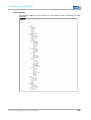
INDEX
ABOUT US .......................................................................................................................................... 6
1
NOTES ..................................................................................................................................... 7
1.1
RELEVANT UNIT DOCUMENTATION ....................................................................................................7
1.2
DESCRIPTION OF THE WARNING SYMBOLS USED IN THIS GUIDE................................................................. 7
1.3
DATA, IMAGES, AMENDMENTS AND VARIATIONS ................................................................................... 7
1.4
TRADEMARKS ..............................................................................................................................7
1.5
COPYRIGHT ................................................................................................................................ 8
1.6
STANDARDS ................................................................................................................................ 8
OPERATING AND SAFETY INSTRUCTIONS........................................................................................ 9
2
2.1
SAFETY INSTRUCTIONS ..................................................................................................................9
2.2
UNIT OPERATION SITE ................................................................................................................ 10
2.3
DAMAGES DUE TO IMPROPER USE ................................................................................................... 10
2.4
WARRANTY / REPAIRS ................................................................................................................. 10
2.5
GENERAL DIRECTIONS FOR THE 5GHZ VERSION (802.11 A / 802.11 H) ETSI ........................................ 10
2.6
ANTENNA LIST FOR USE IN USA AND CANADA / FCC ........................................................................... 11
2.7
CHANNEL LIST FOR USE IN USA AND CANADA / FCC ........................................................................... 12
2.8
WLAN INSTRUCTIONS ................................................................................................................ 12
INTRODUCTION ....................................................................................................................... 13
3
3.1
RAP AND RAC VERSIONS ............................................................................................................. 14
3.2
SCOPE OF SUPPLY ...................................................................................................................... 16
3.3
ENVIRONMENTAL CONDITIONS....................................................................................................... 16
4
MOUNTING ............................................................................................................................. 17
4.1
MOUNTING CONDITIONS .............................................................................................................. 17
4.2
EXTERIOR DEVICE DIMENSIONS ..................................................................................................... 17
4.3
MOUNTING DIAGRAM .................................................................................................................. 19
4.4
DEVICE MOUNTING..................................................................................................................... 20
4.5
CONNECTING SUPPLY LINES .......................................................................................................... 21
4.6
ANTENNA ASSEMBLY ................................................................................................................... 23
5
SYSTEM FEATURES ................................................................................................................... 24
5.1
LED STATUS INDICATORS ............................................................................................................ 24
5.2
LED STATUS INDICATORS DURING OPERATION .................................................................................. 25
5.3 INTERFACE OVERVIEW ................................................................................................................. 28
5.3.1 Power Supply 24V DC .............................................................................................................. 28
5.3.2 Power Supply 110/230 VAC ..................................................................................................... 29
5.3.3 Power Supply HOST (IEEE 802.AF)......................................................................................... 29
5.3.4 Fibre Optic Ethernet .................................................................................................................. 29
5.3.5 SIM Card Reader, ISO 7816-compatible .................................................................................. 30
6
INITIAL DEVICE OPERATIONS .................................................................................................... 31
6.1
FIRST-TIME CONFIGURATION ........................................................................................................ 31
6.2
MANUAL NETWORK ADAPTER CONFIGURATION VIA RJ45/OPTICAL CABLE ................................................. 31
6.3
WLAN NETWORK ADAPTER CONFIGURATION .................................................................................... 33
© ads-tec GmbH • Raiffeisenstr.14 • 70771 Leinfelden-Echterdingen
3
IT Infrastructure RAP/RAC1000
6.4
FIRST-TIME CONFIGURATION VIA WEB INTERFACE ............................................................................. 35
6.5
WIRELESS NETWORK CONFIGURATION ............................................................................................ 36
6.6
ESTABLISHING A WIRELESS NETWORK CONNECTION ........................................................................... 36
ACCESS POINT SETUP WIZARD .................................................................................................. 37
7
7.1 FIRST-TIME CONFIGURATION USING THE SETUP WIZARD ..................................................................... 37
7.1.1 Language Selection .................................................................................................................. 37
7.1.2 IP Configuration ........................................................................................................................ 38
7.1.3 WLAN-1 Configuration ............................................................................................................. 40
7.1.4 WLAN-1 Security ...................................................................................................................... 43
7.1.5 Changing the Password ........................................................................................................... 46
7.2 CONFIGURATION USING THE FILTER WIZARD .................................................................................... 48
7.2.1 Adding a Rule set ..................................................................................................................... 48
7.2.2 Changing and Searching existing Rule Sets ............................................................................ 49
7.2.3 Loading pre-configured Rule sets ............................................................................................ 50
7.2.4 Definition of a new Rule set on Layer 2 ................................................................................... 52
7.2.5 Definition of a new Rule set on Layer 3 ................................................................................... 62
8
ACCESS POINT/CLIENT WEB INTERFACE ..................................................................................... 75
8.1 DIAGNOSTICS MAIN MENU ITEM ..................................................................................................... 75
8.1.1 System status ........................................................................................................................... 75
8.2 GENERAL OVERVIEW FOR CONFIGURATION IN THE MENUS ..................................................................... 76
8.2.1 IP routing exemplary configuration ........................................................................................... 77
8.2.2 Error messages ........................................................................................................................ 79
8.2.3 Eventlog .................................................................................................................................... 80
8.2.4 ICS-Status ................................................................................................................................ 81
8.2.5 HOST ........................................................................................................................................ 81
8.2.6 Ping test .................................................................................................................................... 82
8.2.7 Remote Capture ....................................................................................................................... 83
8.3 MAIN MENU ITEM CONFIGURATION ................................................................................................. 83
8.3.1 IP configuration......................................................................................................................... 83
8.3.2 WLAN-1 Parameter .................................................................................................................. 90
8.4
WLAN-1 SECURITY ................................................................................................................... 98
8.5
STATIC MAC ADDRESS .............................................................................................................. 102
8.6
FILTER WIZARD ....................................................................................................................... 104
8.7 BASIC SETTINGS ...................................................................................................................... 105
8.7.1 Access Authorization .............................................................................................................. 110
8.7.2 Adv. WLAN ............................................................................................................................. 114
8.7.3 Sonstiges ................................................................................................................................ 118
8.7.4 Network .................................................................................................................................. 119
8.7.5 Service .................................................................................................................................... 126
8.8
PRIORITISATION ...................................................................................................................... 132
8.9 SYSTEM................................................................................................................................. 134
8.9.1 Backup settings ...................................................................................................................... 134
8.9.2 Factory defaults ...................................................................................................................... 138
8.10
INFORMATION...................................................................................................................... 140
8.10.1
General ............................................................................................................................... 140
8.10.2
Technical data ..................................................................................................................... 141
4
© ads-tec GmbH • Raiffeisenstr.14 • 70771 Leinfelden-Echterdingen
IT Infrastructure RAP/RAC1000
8.10.3
8.10.4
8.10.5
9
Hardware installation ........................................................................................................... 142
Local diagnostics ................................................................................................................. 142
Sitemap................................................................................................................................ 143
REGULATORY APPROVALS ....................................................................................................... 144
9.1
EUROPEAN APPROVALS .............................................................................................................. 144
9.2
CHANNELLISTS ........................................................................................................................ 146
9.4
5 GHZ DFS REGULATION AFTER ETSI EN 301 893 V1.4.1 WITHIN THE EU .................................. 154
9.5
FCC-APPROVAL ....................................................................................................................... 155
9.6
DIRECTIVES ............................................................................................................................ 156
10
TECHNICAL DETAILS............................................................................................................... 157
10.1
RAP AND RAC VERSIONS ........................................................................................................ 157
10.2
ETHERNET DATA TRANSMISSION ............................................................................................... 157
10.3
RADIO PROPERTIES ............................................................................................................... 158
10.4
POWER SUPPLY .................................................................................................................... 158
10.5
CONFIGURATION ................................................................................................................... 158
10.6
GENERAL DATA .................................................................................................................... 158
11
SERVICE AND SUPPORT ........................................................................................................... 159
11.1
ADS-TEC SUPPORT................................................................................................................. 159
11.2
COMPANY ADDRESS ............................................................................................................... 159
12
EXAMPLES OF USE .................................................................................................................. 160
12.1
PRIORITIZATION ................................................................................................................... 160
12.2
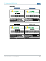
CERTIFICATES ...................................................................................................................... 163
12.3
SIM CARD .......................................................................................................................... 187
12.4
USB PRINTER ...................................................................................................................... 189
12.5
OVERVIEW OF CLIENT OPERATION MODES .................................................................................. 191
12.6
EXTENDED BACKGROUND SCANNING AND ROUTER ......................................................................... 193
12.7
SEAMLESS ROAMING .............................................................................................................. 197
12.8
EXTENDED BACKGROUND SCANNING .......................................................................................... 202
12.9
EXTENDED ROAMING PARAMETERS ............................................................................................ 205
12.1
REMOTE CAPTURE ................................................................................................................. 210
12.1
CERTIFICATION BRASIL .......................................................................................................... 214
© ads-tec GmbH • Raiffeisenstr.14 • 70771 Leinfelden-Echterdingen
5
IT Infrastru
ucture RAP/RAC1000
ABOUT US
S
ads-tec GmbH
Raiffeisenstr. 14
D-70771 Leinfelden-Echterdingen
894-0
Tel: +49 711 458
Fax: +49 711 458
894-990
www.ads-tec.com
ads-tec GmbH provides large enterprises and globally active corporrations with cutting edge
technology, up-to--date know-how and comprehensive services in the area of automation
technology, data processing
p
technology and systems engineering.
plements full automation solutions from planning to commissioning and is
ads-tec GmbH imp
specialized in hand
dling and material handling technologies.
The data systems division develops and produces PC based soluttions and offers a broad
range of industrial PCs, thin clients and embedded systems.
ads-tec is speciallized in modifying and optimizing embedded operating systems and
develops software tools to complement its hardware platforms.
6
© ads-tec GmbH • Raiffeisenstr
str.14 • 70771 Leinfelden-Echterdingen
IT Infrastructure RAP/RAC1000
1 NOTES
1.1
RELEVANT UNIT DOCUMENTATION
The following documents are essential to unit setup and operation:
USER MANUAL (THIS DOCUMENT)
Contains information on mounting, placing into operation and operation of the unit, further
to technical data on unit hardware.
SERVICE CD:
Contains the User Manual, the Assembly Guide, the Quick Install Guide and Tools.
Contai ns the Us er M anual, the Assembl y Gui de, the Quic k Install Guide and Tool.
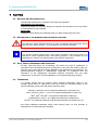
1.2
DESCRIPTION OF THE WARNING SYMBOLS USED IN THIS GUIDE
Warning:
The “Warning” symbol precedes warnings on uses or operations that might either lead to
personal injury and/or hazards, or to any hardware and software damages.
Note:
This Symbol indicates special notes, terms and/or conditions that strictly need to be
observed to ensure optimised and/or zero-defect operations. It also precedes tips and
suggestions for efficient unit implementation and software optimisation.
1.3
DATA, IMAGES, AMENDMENTS AND VARIATIONS
All texts, data and figures are non-binding. We reserve the right of modification in
accordance with technological progress. At that point in time when the products leave our
premises, they comply with all currently applicable legal requirements and regulations. The
operator/operating company is independently responsible for compliance with and
observance of any subsequently introduced technical innovations and new legal
requirements, as well as for all usual obligations of the operator/operating company.
1.4
TRADEMARKS
It is hereby notified that any software and/or hardware trademarks further to any
company brand names as mentioned in this User’s Guide are all strictly subject to the
various trademark, brand name and patent protection rights.
Windows®, Windows® CE are registered trademarks of Microsoft Corp.
Intel®, Pentium®, Atom™ , Core™2 are registered trademarks of Intel Corp.
IBM®, PS/2® and VGA® are registered trademarks of IBM Corp.
CompactFlash™ and CF™ are registered trademarks of SanDisk Corp.
RITTAL® is a registered trademark of the Rittal Werk Rudolf Loh GmbH & Co. KG.
Any further additional trademarks and/or brand names herein, be they domestic or
international, are hereby duly acknowledged.
© ads-tec GmbH • Raiffeisenstr.14 • 70771 Leinfelden-Echterdingen
7
IT Infrastructure RAP/RAC1000
1.5
COPYRIGHT
This User’s Guide inclusive of all the images it contains is entirely proprietary and subject
to copyright. Any irregular use of this Guide by third parties infringing copyright terms is
thus strictly forbidden. Reproduction, translation, as well as electronic and photographic
image storage and/or amendment processes, are subject to prior written authorisation
directly by M/s. ads-tec GmbH.
Any violation and infringement thereto will be held liable for compensation of all damages.
1.6
STANDARDS
This unit is compliant with the provisions and safety objectives of the following EU
Directives:
•
This unit is compliant with the CE mark testing specification limits as defined in the
European test standards EN 61000-6-4 und EN 61000-6-2
•
This unit is compliant to the DIN EN 60950 (VDE0805, IEC950) testing
specification limits on “Safety of Information Technology Equipment”
•
This unit is compliant to the DIN EN 60068-2-6 (sinusoidal vibration) testing
specification limits
•
This unit is compliant to the DIN EN 60068-2-27 (shock and bump) testing
specification limits
Note:
A corresponding declaration of conformity is available for competent authorities, care of
the Manufacturer. Said declaration can be viewed at all times upon request.
For full compliance to the legal requirements in force on electromagnetic compatibility, all
components and cables used for unit connection must also be compliant with said
regulations. It is therefore necessary to employ BUS and LAN cables featuring screened
plug connectors, to be strictly installed as per the instructions contained in the User
Manual.
8
© ads-tec GmbH • Raiffeisenstr.14 • 70771 Leinfelden-Echterdingen
IT Infrastructure RAP/RAC1000
2 OPERATING AND SAFETY INSTRUCTIONS
The unit operates under electrical tension and implements supersensitive component parts.
Intervention by the User is required only for power supply line connection operations.
Should any further alterations be required, it is necessary to consult either with the
Manufacturer directly or with authorised service personnel accordingly. During said
connection operations, the unit must be completely powered down. Specific requirements
need to be met concerning the prevention of electrostatic discharge on component
construction parts during contact. If the unit is opened up by a non authorised individual,
the User may be subject to potential hazards and, warranty conditions are terminated.
General Instructions:
•
•
•
•
•
•
This User’s Guide must be read and understood by all Uses and must be available
for consultation at all times
Mounting, operation start-up and unit operation must only be conducted by
appropriately qualified and trained personnel
All individuals and operators using the unit must strictly observe all safety and use
instructions as provided within the User’s Guide
All regulations and prescriptions on accident prevention and safety in force at the
unit installation site must be strictly observed at all times
This User’s Guide provides all the most important directions as required for safe
and security oriented operation
Safe and optimised unit operations are subject to appropriate storage, proper
transport and handling, accurate unit setup, start-up and operation
Note:
Only original ads-tec firmware / software is allowed for any of the adjustments and
features described in this User’s Guide. Deployment of any firmware / software that has
not been released by ads-tec will terminate all warranty conditions.
2.1
SAFETY INSTRUCTIONS
Warning:
In order to prevent possible unit damages, all cable lines (power supply, interface cables)
must be hooked up strictly with the unit in power-OFF conditions.
Warning:
All unit mounting operations must be strictly conducted under safe, secure and zeropotential conditions.
Note:
When handling parts and components susceptible to electrical discharge, please
accurately observe all the relevant safety provisions.
(DIN EN 61340-5-1 / DIN EN 61340-5-2)
© ads-tec GmbH • Raiffeisenstr.14 • 70771 Leinfelden-Echterdingen
9
IT Infrastructure RAP/RAC1000
2.2
UNIT OPERATION SITE
This unit is engineered for industrial application. It is necessary to ensure that specified
environmental conditions are maintained at all times. Unit implementation in non-specified
surroundings, i.e. onboard ships, in explosive atmospheres or at extreme heights, is
prohibited.
Warning:
For the prevention of water condensate accumulation, the unit should be turned ON only
when it reaches ambient temperature. This particularly applies when the unit is subject to
extreme temperature fluctuations and/or variations.
Avoid overheating during unit operations; the unit must not be exposed to direct sunlight
or any other direct light or heat sources.
Warning:
This is a Class A device. In a domestic environment this device may cause radio
frequency (RF) interference, in which case the user may be required to take adequate
measures.
Warning:
If the unit is operated in outdoor locations, a lightning conductor needs to be present
within capture range. Ensure that all incoming conductive systems are equipped with
equipotential bonding.
2.3
DAMAGES DUE TO IMPROPER USE
Should the service system have evident signs of damages incurred e.g. due to wrong
operation or storage conditions or due to improper unit use, the unit must be
decommissioned or scrapped. Ensure that it is protected against accidental start-up.
2.4
WARRANTY / REPAIRS
During the unit warranty period, any repairs thereto must strictly be conducted solely by
the manufacturer or by service personnel that has been duly authorised by the
manufacturer.
2.5
GENERAL DIRECTIONS FOR THE 5GHZ VERSION (802.11 A / 802.11 H) ETSI
• The unit is certified for use of the 5 GHz band in accordance with ETSI EN 301 893
V1.3.1. Users need to observe the following:
• Access Point as well as Access Client units make use of DFS and TPC as standard on all
5 GHz channels, in indoor as well as in outdoor configuration. This means that the
devices may always be operated at a maximum transmission power of 23 dBm or 30
dBm, respectively.
Note:
Access Points must not switch off DFS in outdoor locations. Access Clients may switch off
DFS, though. This setting is turned off by default.
• 802.11a channels cannot be set to static values.
10
© ads-tec GmbH • Raiffeisenstr.14 • 70771 Leinfelden-Echterdingen
IT Infrastructure RAP/RAC1000
Note:
The lower 4 channels (non-DFS) can be set to static values if DFS is turned off. Turning
off DFS will however also make the features 60s Scan and Radar Detection unavailable.
• When activating the Access Point, the unit will perform an initial Radar Detection Scan
during which it will wait 60 seconds for a radar impulse on a randomly chosen channel.
Subsequently, it will start operating on this channel.
• If an Access Client detects a radar impulse during operation, the Access Point will be
notified of this via 802.11h. Triggered by this or its own detection of the impulse, the
Access Point will subsequently perform a channel switch to 802.11h. The connection
loss in this case is usually less than 80ms.
• The maximum permissible transmission power is different for each channel. Hence
users are required to correctly set the antenna amplification in case the standard
antenna is replaced!
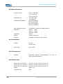
2.6
ANTENNA LIST FOR USE IN USA AND CANADA / FCC
• This antenna types can be used with the Access Points and Access Client in USA and
Canada. The antennas can be ordered at ads-tec GmbH. For the correct operation you
have to use an absorbability cabel for the different antenna types.
Ads-tec part number
Ads-tec part description
Antenna type
Frequency band
Gain
absorbability
DZ-PCKO-11032-0
RAP Antenne 2,4 GHz SMA-R 5dBi
Swivel
2,4 ~ 2,4835 GHz
5 dBi
none
DZ-PCKO-11033-0
RAP Antenne 5 GHz SMA-R 7dBi
Swivel
5,1 ~ 5,835 GHz
7 dBi
none
DZ-PCKO-11034-0
RAP Antenne 2,4 GHz N-fem. 9 dBi
Omni
2,4 ~ 2,4835 GHz
9 dBi
none
DZ-PCKO-11034-1
RAP Antenne 2,4 GHz N-fem. 12 dBi
Omni
2,4 ~ 2,4835 GHz
12 dBi
none
DZ-PCKO-11035-0
RAP Antenne 2,4 GHz N-fem. 12 dBi
Panel
2,4 ~ 2,4835 GHz
12 dBi
none
DZ-PCKO-11035-1
RAP Antenne 2,4 GHz N-fem. 18 dBi
Panel
2,4 ~ 2,4835 GHz
18 dBi
minimum 20m
1
(it is a Ecoflex10* cable to use)
DZ-PCKO-11036-0
RAP Antenne 5 GHz N-fem. 12 dBi
Omni
5,1 ~ 5,835 GHz
12 dBi
minimum 14m
1
(it is a Ecoflex10* cable to use)
DZ-PCKO-11037-0
RAP Antenne 5 GHz N-fem. 12 dBi
Panel
5,1 ~ 5,835 GHz
12 dBi
minimum 20m
1
(it is a Ecoflex10* cable to use)
DZ-PCKO-11037-1
RAP Antenne 5 GHz N-fem. 20 dBi
Panel
5,1 ~ 5,835 GHz
20 dBi
minimum 37m
1
(it is a Ecoflex10* cable to use)
1
* It has at 2,4GHz 22.5dB/100m absorbability and at 5GHz 35.9dB/100m absorbability. Additional every plug has 0.5dB absorbability.
Warning:
Behalf of the correct operation you have use an absorbability element for the different
antenna types.
Note:
Also light wave conductor cable can be used. It is necessary to use terminating
impedance for the correct use.
© ads-tec GmbH • Raiffeisenstr.14 • 70771 Leinfelden-Echterdingen
11
IT Infrastructure RAP/RAC1000
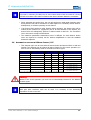
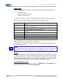
2.7
CHANNEL LIST FOR USE IN USA AND CANADA / FCC
• The following List showes the pool of available frequency and channles for the use in
USA and Canada. The customer can define between Indoor and Outdoor use. This
option can be selected by a checkbox in the web interface.
Frequency
2,4 GHz (2.400~2.483GHz)
Indoor use
Outdoor use
X
1 – 11
X
36,40,42,44,48
X
5 GHz (5.725~5.825GHz)
149 ,153,157,161,165
X
5 GHz (5.725~5.825GHz)
149 ,153,157,161,165
5 GHz (5.18~5.24GHz)
2.8
Channel
X
WLAN INSTRUCTIONS
Warning:
These warnings need to be observed during operation:
•
The unit does not provide a „secure“ transmission medium
•
The units cannot be used to establish a real-time system
•
The units’ system behaviour is non-deterministic
•
MIN/MAX roaming period is not guaranteed
Setting the applicable regulatory authority as well as the respective antenna amplification
is solely the responsibility of the operator.
12
© ads-tec GmbH • Raiffeisenstr.14 • 70771 Leinfelden-Echterdingen
IT Infrastructure RAP/RAC1000
3 INTRODUCTION
Reliable, stable and secure wireless LAN connections: employing state-of-the-art
technology, the industrial Rugged Access Point (RAP) provides the network interface for a
variety of applications, such as commissioning, mobile computing and data communication.
The RAP supports all applicable standards, including 802.11a/b/g, at a transmission
frequency of 2.4 and 5 GHz. Industrial applications necessitate sturdy technology. Whether
installed in a cold store or in great heat – thanks to its extended temperature range, the
RAP continues to function. Furthermore, the RAP is MIL-certified, which means it passed
one of the most demanding shock and vibration tests – this guarantees utmost
ruggedness.
Note:
In Case of Updates, it is possible that external Hyperlinks, which are used in this
Documentation, will not work properly or may be available under a different
Hyperlink.The Company ads-tec (also “ads-tec”) does not take over any kind of warranty
or adhesion for the functionality of Hyperlinks. Furthermore, ads tec does not take over
any kind of warranty or adhesion regarding the installation, use and the accuracy of all
open SOURCE software.
Note:
For the efficient online configuration of your ads tec devices, it is possible to download
the current version of the free Tool „IDA light “on the company`s homepage
http://www.ads-tec.de. The Tool offers you for example the possibility of defining
individual parameters or whole groups of parameters at a master device and to transfer
your settings to a limited selection and/or to all ads tec devices of same design and
version, without having to make these configurations time-consuming at each individual
device. You also have the possibility of assigning sequential IP addresses for your ads tec
devices.
With IDA light you can provide comfortably own groups of parameters according to your
specific requirements and modify them at any time.
Note:
This documentation always refers to both Access Point and Access Client, unless explicitly
stated otherwise.
© ads-tec GmbH • Raiffeisenstr.14 • 70771 Leinfelden-Echterdingen
13
IT Infrastructure RAP/RAC1000
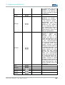
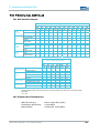
3.1
RAP AND RAC VERSIONS
RAP – Rugged Access Point
1 WLAN module
Radio
modules
RAP
1110
RAP
1111
RAP
1210
RAP
1211
x
x
x
x
x
x
2 WLAN module s
1x Cu-RJ45 port
4x Cu-RJ45 port
(switch)
1x fibreoptic
Ethernet port
24 V DC
AC integrated
110/230 V
Redundant energy
supply
RAP incl. client
mode
Seamless
Roaming Client*
Ports
Power
supply
Client
mode
x
x
x
RAP1000 series
RAP
RAP
RAP
1121 1220 1221
RAP
1120
x
x
x
x
x
x
x
x
x
x
x
x
x
x
x
x
x
RAP
1511
RAP
1520
RAP
1521
x
x
x
x
x
x
x
x
x
x
x
x
x
x
x
x
x
x
RAP
1510
x
x
x
x
x
x
x
x
x
x
x
x
x
x
x
x
x
x
x
x
x
x
x
x
x
x
x
x
x
x
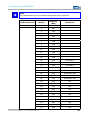
RAC – Rugged Access Client
RAC
1120
Radio modules
Ports
RAC1000 series
RAC
RAC
RAC
1121 1220 1221
1 WLAN module
RAC2000 series
RAC
RAC
2110
2120
x
2 WLAN modules
x
x
1x Cu-RJ45 port
x
x
x
x
x
x
x
x
x
x
x
x
x
x
x**
x**
4x Cu-RJ45 port (switch)
Power supply
Client mode
1x fibreoptic Ethernet port
24 V DC
AC integrated 110/230 V
Redundant energy supply
x
x
x
x
x
x
x
x
RAP incl. client mode
Seamless Roaming Client*
x
* Seamless Roaming Clients: From access point to access point without any packet loss or interruption of data
transmission
**12 – 24V
14
© ads-tec GmbH • Raiffeisenstr.14 • 70771 Leinfelden-Echterdingen
IT Infrastructure RAP/RAC1000
RJ45 (Registered Jack 45 = standardised jack) is an Ethernet standard frequently
used in telecommunication applications. Transmission method is equivalent to 10/100Mbits
half & full DUPLEX 100 BASE-TX.
Optical fibres are flexible optic media for controlled conduction of light. Contrarily to the
Ethernet standard, the fibre optic connection technology is insensitive to voltage
interference.
The plugs required for implementation are equivalent to the MTRJ Standard Multimode
with a 100Base-FX 100 Mbit⁄s Ethernet transmission via fibre optics.
© ads-tec GmbH • Raiffeisenstr.14 • 70771 Leinfelden-Echterdingen
15
IT Infrastructure RAP/RAC1000
3.2
SCOPE OF SUPPLY
Package contents need to be checked for integrity and completeness:
•
1 device
•
1 x two-pole COMBICON plugs (in case of 24V DC devices)
Manufacturer: Phoenix Contact
Item description/item short text: FMC 1,5 / 2-STF-3,5
•
1 x three-pole COMBICON plugs (in case of 230V AC devices)
Manufacturer: Phoenix Contact
Item description/item short text: MC 1,5 / 3-ST1F-5,08
3.3
•
Four or eight antennas (depending on variant)
•
Grommets / blanking plugs
•
Installation kit with mounting plate and fasteners (fixed to device)
•
Quick Install Guide / Quick Mount Guide
•
GNU General Public License
•
Service CD
ENVIRONMENTAL CONDITIONS
The unit can be put into operation and used under the following conditions. Failure to
observe any one of the specified data will immediately terminate all warranty conditions.
ads-tec cannot be held liable for any damages arising due to improper device or unit use
and handling.
•
•
•
Permissible ambient temperature
during operation
from -20 … 55° C
during storage
from -20 … 55° C
Humidity
during operation
10 to 85%, without condensate
during storage
10 to 85%, without condensate
Vibration
during operation
1 G, 10 to 500 Hz
(DIN EN 60068-2-6)
Vibration certificate:
MIL-STD-810F 514.5 C-2
5 to 500 Hz (01-01-2000)
•
Shock
during operation
5 g, with a 30 ms half-cycle
(DIN EN 60068-2-29)
16
© ads-tec GmbH • Raiffeisenstr.14 • 70771 Leinfelden-Echterdingen
IT Infrastructure RAP/RAC1000
4 MOUNTING
4.1
MOUNTING CONDITIONS
The device is designed for industrial operations and may be employed wherever the
environment conditions specified above are met. In order to ensure optimal mounting and
operation, the unit should be placed at suitable location at which WLAN connectivity is not
impaired. WLAN connectivity is adversely influenced by iron beams and thick concrete
walls.
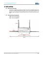
4.2
EXTERIOR DEVICE DIMENSIONS
Height: 160 mm (w/o antenna)
Width: 250 mm (w/o antenna)
Depth: 65 mm (w/o antenna)
© ads-tec GmbH • Raiffeisenstr.14 • 70771 Leinfelden-Echterdingen
17
IT Infrastructure RAP/RAC1000
18
© ads-tec GmbH • Raiffeisenstr.14 • 70771 Leinfelden-Echterdingen
IT Infrastructure RAP/RAC1000
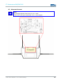
4.3
MOUNTING DIAGRAM
Note:
The mounting diagram shown herein is not 1:1 scale.
Please refer to the Quick Install Guide for a 1:1 scale diagram.
© ads-tec GmbH • Raiffeisenstr.14 • 70771 Leinfelden-Echterdingen
19
IT Infrastructure RAP/RAC1000
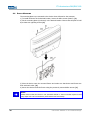
4.4
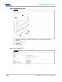
DEVICE MOUNTING
The mounting plate is pre-mounted to the device when delivered to the customer.
1) To install the device in the desired location, loosen the Allen screws (M4x12). (1)
2) Fix the mounting plate (w/o device) in the desired location. Ensure that the plate is held
by at least two opposing screws. (2)
3) Place the device onto the mounted fixture and make sure that device and fixture are
flush with each other. (3)
4) Secure the device inside the fixture using the previously removed Allen screws. (1)
Note:
Please ensure that the device is not mounted behind or next to another object as this
may impair the unit’s transmission performance and connectivity.
20
© ads-tec GmbH • Raiffeisenstr.14 • 70771 Leinfelden-Echterdingen
IT Infrastructure RAP/RAC1000
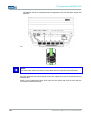
4.5
CONNECTING SUPPLY LINES
The supply connection, as well as device interfaces, is located inside the unit. The
maintenance duct cover needs to be removed before supply lines and interface cables can
be connected.
Please remove the five screws (M3x8) indicated below.
Warning:
To avoid damage to the unit’s electronics, switch off the device before establishing or
removing any plug connections.
Observe permissible device voltage.
Once the maintenance duct cover has been removed, the supply lines can be
connected to the device.
© ads-tec GmbH • Raiffeisenstr.14 • 70771 Leinfelden-Echterdingen
21
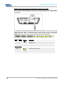
IT Infrastructure RAP/RAC1000
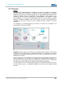
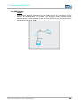
The diagram shows an exemplary device configuration with 24V DC power supply and
host line.
To ensure IP65 protection all supply lines need to be fitted with suitable grommets.
Note:
Grommet sizes need to be chosen in accordance with the respective cable diameters.
Once the grommets have been placed around the cables, they need to be placed into the
intended slots.
Finally, put the maintenance duct cover back onto the device and screw it down with the
five screws removed previously.
22
© ads-tec GmbH • Raiffeisenstr.14 • 70771 Leinfelden-Echterdingen
IT Infrastructure RAP/RAC1000
4.6
ANTENNA ASSEMBLY
For each WLAN module, 2 antennas should be installed.
Depending on the device variant, the unit accommodates up to two radio modules for two
separate WLANs. The full antenna assembly for each module consists of one vertical and
one horizontal antenna. The four or eight antennas supplied work at a frequency of
2.5GHz or 5Ghz (two or four each, respectively).
Screw the antennas onto the antenna connectors.
© ads-tec GmbH • Raiffeisenstr.14 • 70771 Leinfelden-Echterdingen
23
IT Infrastru
ucture RAP/RAC1000
5 SYSTEM FEATU
URES
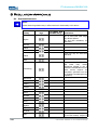
5.1
LED STATUS INDICATTORS
The device is fitte
ed with LEDs that indicate the status of the resspective interfaces. This
facilitates an on-ssite status diagnosis of the Access Point/Client. The following overview
explains the differe
ent states of the LED indicators:
LEGEND
LED status
Shown in table as
off
green
green, flashing
ret
orange
orange, flashing
POWER SUPPLY / HOST
H
/ SWITCH
POWER
STATUS
DESCRIPTION
PWR
No power supply.
PWR
Device connected to power supply and ready for
use.
HOST
24
LEFT LED
LINK
Interface not connected to remote sttation.
LEFT LED
LINK
Interface connected to remote station
n and ready for
use.
RIGHT LED
ACT
No data transfer between device
e and remote
station.
Right LED
ACT
Indicates data transfer between device and remote
station.
© ads-tec GmbH • Raiffeisenstr
str.14 • 70771 Leinfelden-Echterdingen
IT Infrastructure RAP/RAC1000
SWITCH
1/2/3/4
5.2
LEFT LED
LINK
Interface not connected to remote station.
LEFT LED
LINK
Interface connected to remote station and ready for
use.
RIGHT LED
ACT
No data transfer between device and remote
station.
Right LED
ACT
Indicates data transfer between device and remote
station.
LED STATUS INDICATORS DURING OPERATION
BEHAVIOUR OF STATUS INDICATORS DURING BOOT SEQUENCE
The boot sequence is initiated as soon as the Access Point / Client is connected to a power
supply. The HOST indicator LEDs can be used to monitor the boot sequence. Please refer
to the following overview to verify the device boots correctly. The overview assumes that
no cable is connected to HOST.
PWR
STATUS
L+
DESCRIPTION
Device is connected to power supply via POWER and
ready for use.
HOST
LINK / ACT
LEDS FLASH BRIEFLY ONCE
LED FLASHES SLOWLY, THEN QUICKLY (20X)
LED EXTINGUISHED
© ads-tec GmbH • Raiffeisenstr.14 • 70771 Leinfelden-Echterdingen
25
IT Infrastructure RAP/RAC1000
BEHAVIOUR OR STATUS INDICATORS DURING RESET TO DEFAULT SETTINGS
The reset button located under the interface cover may be used to reset the Access Point /
Client to factory default settings at any time and without regard to the current device
configuration.
To reset device to default settings, press reset button and switch on the device. Keep reset
button pressed for approx. 20 seconds. Button may be released as soon as left HOST
indicator LED turns green. The following overview assumes that no cable is connected to
HOST. Please refer to the overview to monitor the reset to factory defaults.
PWR
L+
STATUS
DESCRIPTION
Device is connected to power supply via POWER and
ready for use.
HOST
26
LINK / ACT
LEDS FLASH CONTINUOUSLY
LINK / ACT
LEDS EXTINGUISHED
© ads-tec GmbH • Raiffeisenstr.14 • 70771 Leinfelden-Echterdingen
IT Infrastructure RAP/RAC1000
BEHAVIOUR OF STATUS INDICATORS DURING FIRMWARE UPDATE
The web interface can be used to perform firmware updates. Once initiated, the actual
update may take several minutes to complete. Please refer to the following overview to
monitor the firmware update sequence.
PWR
STATUS
L+
DESCRIPTION
Device is connected to power supply via POWER and
ready for use.
HOST
LINK / ACT
LEDS FLASH QUICKLY
LINK / ACT
LINK EXTINGUISHED / ACT FLASHES
LINK / ACT
LINK LIT UP / ACT EXTINGUISHED
LINK / ACT
LINK LIT UP / ACT FLASHES SLOWLY
LINK / ACT
LINK LIT UP / ACT FLASHES QUICKLY
LINK / ACT
LINK LIT UP / ACT EXTINGUISHED
THE WEB INTERFACE MAY SUBSEQUENTLY BE STARTED BY SELECTING “TRY TO RECONNECT”
© ads-tec GmbH • Raiffeisenstr.14 • 70771 Leinfelden-Echterdingen
27
IT Infrastructure RAP/RAC1000
5.3
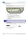
INTERFACE OVERVIEW
The following figure shows the available device interfaces. The exact interfaces may differ
depending on the device variant.
The device is equipped with the following interfaces:
1. Power 24V DC power supply (two-pole COMBICON plug)
2. Power 230V AC power supply (three-pole COMBICON plug)
3. HOST RJ45 or Optical connector
4. SWITCH 4x RJ45 connector (optional feature for Access Client)
5. Default reset button
6. SIM card reader
Note:
Input voltages may be connected redundantly (i.e. Power 24V DC, Power 230V AC).
5.3.1
POWER SUPPLY 24V DC
A bushing terminal with threaded connector is used to establish the power supply
connection (diagram shows bushing inside device).
PIN NUMBER
SIGNAL NAME
1
24V DC
2
0V DC
PIN 1: = L+
24V DC power supply
PIN 2: = GND Ground
28
© ads-tec GmbH • Raiffeisenstr.14 • 70771 Leinfelden-Echterdingen
IT Infrastructure RAP/RAC1000
5.3.2
POWER SUPPLY 110/230 VAC
A bushing terminal with threaded connector is used to establish the power supply
connection (diagram shows bushing inside device).
5.3.3
PIN NUMBER
SIGNAL NAME
1
110/230 V AC
2
PE
3
0 V DC
POWER SUPPLY HOST (IEEE 802.AF)
PIN NUMBER
SIGNAL NAME
1
TX +
2
TX -
3
RX +
4
G
5
G
6
RX -
7
-48V
8
-48V
Note:
Transmission of 48V DC power supply is designed for a maximum feeding distance of 100
meters (approx. 330 ft.) in accordance with Ethernet specification requirements. The
connected devices may draw 350 mA of power; maximum supply power is 15.4 Watts.
5.3.4
FIBRE OPTIC ETHERNET
The optical connection requires an MTRJ fibre optic connector.
Multimode cable, MTRJ connector to Duplex connector 62.5/125µm.
© ads-tec GmbH • Raiffeisenstr.14 • 70771 Leinfelden-Echterdingen
29
IT Infrastructure RAP/RAC1000
5.3.5
SIM CARD READER, ISO 7816-COMPATIBLE
The SIM card reader is used for saving configuration data.
PIN NUMBER
SIGNAL NAME
1
VCC 5 Volt
2
RESET
3
CLOCK
4
n/c
5
GND
6
n/c
7
I/O
8
n/c
Note:
Interface and supply connectors are located on the bottom of the device. Secure
plugs against slipping out.
30
© ads-tec GmbH • Raiffeisenstr.14 • 70771 Leinfelden-Echterdingen
IT Infrastructure RAP/RAC1000
6 INITIAL DEVICE OPERATIONS
6.1
FIRST-TIME CONFIGURATION
Warning:
First-time configuration of the device can only be performed via RJ45/optical interface
marked HOST.
AN RJ45 PATCH CABLE IS REQUIRED FOR FIRST-TIME CONFIGURATION.
Connection of 24V DC voltage supply
The device may be powered by a 24V DC (two-pole plug) voltage supply source. The
required COMBICON plugs are supplied with the device.
Connect the device to the appropriate voltage supply source.
Connection of RJ45 / optical network cable
For first-time device operations, a connection between the device and a PC via an
RJ45/optical network cable is strictly required.
Connect the device to a PC:
Device HOST connector <-> PC LAN adapter
6.2
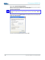
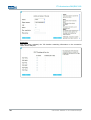
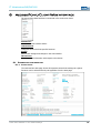
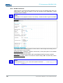
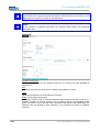
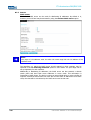
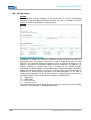
MANUAL NETWORK ADAPTER CONFIGURATION VIA RJ45/OPTICAL CABLE
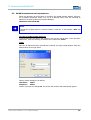
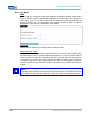
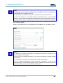
Note:
The following directions and screenshots refers to settings in Windows XP®. The paths and
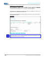
properties described herein may differ for other operating systems.
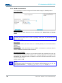
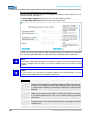
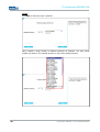
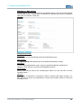
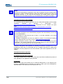
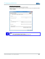
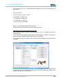
Open the Properties tab for the network adapter in use. The path is as follows:
Start> Control Panel > Network Connections > Local Area Connection >
Properties.
Select Internet Protocol (TCP/IP) in the dialogue window that comes up and then click
Properties.
© ads-tec GmbH • Raiffeisenstr.14 • 70771 Leinfelden-Echterdingen
31
IT Infrastructure RAP/RAC1000
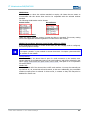
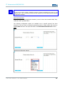
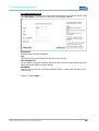
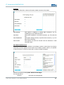
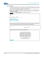
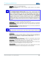
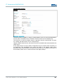
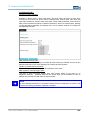
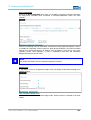
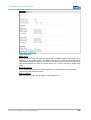
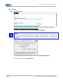
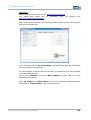
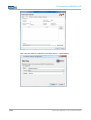
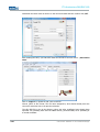
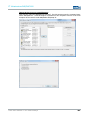
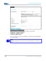
Click to select: Use the following IP address
Access to the device is only possible when the following parameters are set as the static IP
address or if the computer is located in the same subnet space:
IP ADDRESS: 192.168.0.100
Note:
The last set of digits must be a number between 1 and 253. In the example, “100” was
chosen.
Once the IP address has been entered, the subnet mask address must be set as well.
Clicking directly into the field Subnet mask will automatically set the correct subnet mask.
SUBNET MASK: 255.255.255.0
You may now close the dialogue windows by clicking “OK”.
32
© ads-tec GmbH • Raiffeisenstr.14 • 70771 Leinfelden-Echterdingen
IT Infrastructure RAP/RAC1000
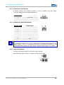
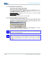
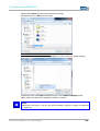
6.3
WLAN NETWORK ADAPTER CONFIGURATION
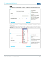
Follow the directions as given above to configure the WLAN network adapter. However,
the IP address parameter needs to be set to a different value. Enter the following IP
address in the Internet Protocol properties dialogue:
IP ADDRESS: 192.168.0.200
Note:
The last set of digits must be a number between 1 and 253. In the example, “200” was
chosen.
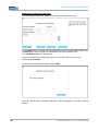
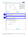
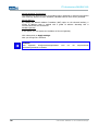
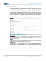
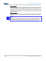
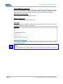
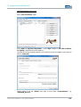
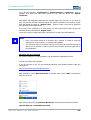
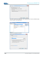
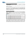
CALLING UP THE DEVICE WEB INTERFACE
To access and open the device web interface, start up your web browser. In the browser’s
address bar, enter the following IP address then confirm with “Enter”.
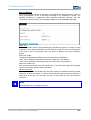
Login
Once the IP address has been entered and confirmed, the login prompt appears. Enter the
default values in the login panel.
Factory default settings are as follows:
USER NAME :
admin
PASSWORD :
admin
Confirm your input by clicking OK. The device web interface will subsequently appear.
© ads-tec GmbH • Raiffeisenstr.14 • 70771 Leinfelden-Echterdingen
33
IT Infrastructure RAP/RAC1000
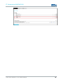
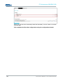
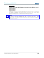
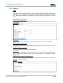
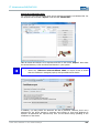
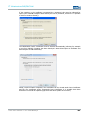
Note:
If the login prompt does not appear ensure that the device has been connected via a
RJ45/optical cable. Otherwise, connect the device to a PC (Device HOST connector <> PC
LAN adapter).
If there still is no connection to the firewall login prompt check your proxy and local
firewall settings. It is often the case that local subnet addresses (e.g. 192.168.x.x) are
diverted to a proxy server. In this case it is possible to select the “Bypass proxy server for
local addresses” check box and enter the address spaces in question.
34
© ads-tec GmbH • Raiffeisenstr.14 • 70771 Leinfelden-Echterdingen
IT Infrastructure RAP/RAC1000
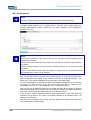
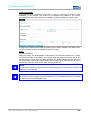
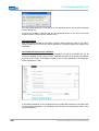
6.4
FIRST-TIME CONFIGURATION VIA WEB INTERFACE
ACTIVATING WLAN MODULE(S)
Go to the following web interface page to activate the WLAN module(s):
BASIC SETTINGS>INTERFACES>WLAN 1/2
Depending on the actual device variant, the unit is equipped with one or two WLAN
modules. Activate the desired WLAN module by checking the Activate Interface check
box in the web interface.
WLAN MODULE CONFIGURATION:
Operating Mode:
The device operating mode needs to be set. Available options are Access Point and
Client.
Network Name (SSID)
The SSID is the visible name of the WLAN. The default setting is ads.
You may choose to set the SSID to any alphanumeric value.
WLAN Mode:
Select your preferred WLAN mode:
Warning:
Only use a WLAN mode that is supported by all of your WLAN devices.
Regulatory Authority:
Select your current location.
Warning:
Setting the applicable regulatory authority as well as the respective antenna amplification
is solely the responsibility of the operator.
Channel:
Default setting: Auto
The device automatically determines the best channel setting.
Saving Configuration Settings:
All changes need to be saved to be activated. To save the modified settings, select the
menu item:
Configuration> Save.
Click Save in the subsequent dialogue window. The current configuration will now be
transmitted and saved.
© ads-tec GmbH • Raiffeisenstr.14 • 70771 Leinfelden-Echterdingen
35
IT Infrastructure RAP/RAC1000
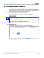
6.5
WIRELESS NETWORK CONFIGURATION
Once again open up the properties panel located at:
Start> Control Panel > Network Connections
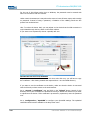
Right-click on your current wireless connection and then select Properties. Now click on
the tab Wireless Networks. In the Preferred Networks section on that tab, click the
button Add. Enter the following parameters:
Network Name SSID: (self-chosen non-default network name), or the default value ads
Network Authentication: Open
Data Encryption: Disabled
You may now close the dialogue windows by clicking “OK”.
6.6
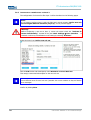
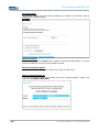
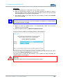
ESTABLISHING A WIRELESS NETWORK CONNECTION
In order to establish a wireless connection to the device, click on the WLAN icon you’re
your taskbar. A window listing all available networks will appear. Select the wireless
network with the appropriate SSID (self-chosen or default name ads) and click on
Connect. The following warning dialogue will pop up:
In order to connect to the WLAN you need to select “Connect Anyway”. The computer
will now establish a wireless connection to the device.
Note:
In case you are unable to establish a connection to the device, we recommend resetting
the device to factory default settings.
Note:
The current configuration does not use date encryption to secure wireless communication
channels. We recommend using data encryption. Please refer to the chapter
Configuration>Security>WLAN 1/2 for details on how to activate and configure
encryption.
36
© ads-tec GmbH • Raiffeisenstr.14 • 70771 Leinfelden-Echterdingen
IT Infrastructure RAP/RAC1000
7 ACCESS POINT SETUP WIZARD
For a simple and fast start-up and configuration of the device, two wizards have been
integrated. The setup wizard leads through the configuration of language settings, the
operation mode and the password. The filter wizard leads through the configuration of
filter rules. Further information is given in the chapter “Packet Filter”. All settings can also
be changed independently of the wizards via the web interface.
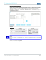
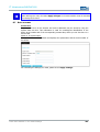
7.1
FIRST-TIME CONFIGURATION USING THE SETUP WIZARD
To perform a basic configuration, select the following under Quick Links:
START SETUP WIZARD
Note:
The question mark
on the right next to the Drop Down menu contains notes and
short explanations on the available menu items.
The notes and short explanations are correctly represented with the Microsoft© Internet
Explorer from version 7 and Mozilla Firefox© from version 1.0.
7.1.1
LANGUAGE SELECTION
Via the dialogue window it is possible to set the user interface language.
The selected language is used for the overall web interface.
Confirm your choice by clicking: Next
© ads-tec GmbH • Raiffeisenstr.14 • 70771 Leinfelden-Echterdingen
37
IT Infrastructure RAP/RAC1000
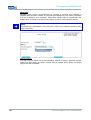
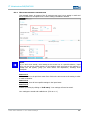
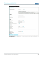
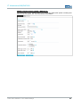
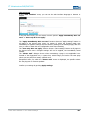
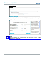
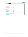
7.1.2
IP CONFIGURATION
The IP configuration settings define the behaviour of the HOST interface. The IP address
may be assigned statically or automatically.
Static:
If this option is selected, it is possible to set a static IP address. Static IP allocation
requires entering the IP address and subnet mask.
Default values are:
IP address:
192.168.0.254
Subnet mask:
255.255.255.0
DHCP:
The DHCP function requests an IP address from a DHCP server and subsequently allocates
IP addresses automatically.
DHCP fallback:
This option allows for automatic IP address allocation. Should there be an error with the
automatic allocation, the IP allocation automatically switches to the static setting.
Activate Spanning Tree Protocol:
The Spanning Tree Protocol (STP) is used to avoid redundant network loops, especially in
switched environments.
If this option is activated, it is possible to establish redundant network connections.
Standard Gateway:
The IP address entered as standard gateway address is used to establish a connection to
an address located outside of the device’s own IP subnet (i.e. outside 192.168.0.254 in the
example given previously). However, the standard gateway itself needs to be inside the
38
© ads-tec GmbH • Raiffeisenstr.14 • 70771 Leinfelden-Echterdingen
IT Infrastructure RAP/RAC1000
device’s IP subnet address space. In case IP allocation was set to DHCP, the standard
gateway address may be dynamically overwritten, providing the DHCP server supports this.
The standard gateway may, for instance, be required in order to reach an NTP time server
or to relay the IP address to WLAN clients in case the device serves as a DHCP server
itself.
Now click Next
© ads-tec GmbH • Raiffeisenstr.14 • 70771 Leinfelden-Echterdingen
39
IT Infrastructure RAP/RAC1000
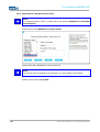
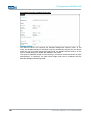
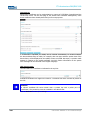
7.1.3
WLAN-1 CONFIGURATION
The next dialogue is used to configure all relevant basic settings for WLAN operation.
Access Point Mode
OPERATING MODE:
Use this option to switch between the two operating modes Access Point and Access
Client.
Note:
The RAC (Access Client) does not offer an operating mode option. It is permanently set to
Access Client mode.
Access Point:
In Access Point mode, the device serves as a network gateway for other wireless devices
(clients).
Access Client:
In Access Client mode, the device tries to establish a connection to an Access Point in
order to establish a connection with the network.
NETWORK NAME (SSID):
Use this option to assign a name to your wireless network. We recommend not using any
names that allow conclusions with regard to your company, department or the type of data
transmitted. Any clients that want to establish a connection with this Access Point need to
know this network name.
Default setting is: ads
Note:
The SSID may consist of a maximum of 32 characters. Valid characters are: a-z, A-Z, 0-9,
valid special characters: . _ - ? $ @ ! { } [ ] ( ) + # ; , < > | : * ~ % $ & / =
40
© ads-tec GmbH • Raiffeisenstr.14 • 70771 Leinfelden-Echterdingen
IT Infrastructure RAP/RAC1000
WLAN MODE:
Use this option to select the wireless standard to employ. All clients that are meant to
communicate with this Access Point need to be compatible with the selected wireless
standard.
The following WLAN modes can be chosen:
ACCESS CLIENT:
ACCESS POINT:
REGULATORY AUTHORITY
Under this option, select the country in which the device is operated. This country setting
ensures that applicable national regulations are observed in each country.
WLAN1 (ACCESS POINT & ACCESS CLIENT) 5 GHZ – 802.11A (ETSI):
If the WLAN 802.11a mode or in case of the client, the 802.11a/b/g mode is configured,
the following options change:
Hinweis:
The Option „Outdoor“ is just available in Access Point Mode. The Option „Deactivate DFS“
is available in both Modes.
Indoor/Outdoor:
Must be enabled if the Access Point is part of a radio connection in the outdoor area.
Certain channels of the 5GHz band may not be used outdoors, and will be excluded by this
option. When used indoors the option indoor can be used. This option is of no importance
for Access Clients.
Disable DFS:
You may disable DFS if the Access Point is NOT used outdoors. You may also manually set
up channels 36, 40, 44 and 48 as fixed channels, in this case. Additionally, the permissible
maximum output power is reduced. In client mode, in contrast to that, DFS may also be
disabled for outdoor use.
© ads-tec GmbH • Raiffeisenstr.14 • 70771 Leinfelden-Echterdingen
41
IT Infrastructure RAP/RAC1000
Note:
In client mode, the DFS function is disabled by default. Caused by the radar detection
during data transmission, strong interferences might occur in particular at the client,
which have to be evaluated as Potential Radar Pulses. A very high CPU load and faulty,
frequently occurring radar detection cycles are results of that. For this reason, DFS should
be enabled in client mode only if the client output power exceeds 23dB, and if 30dBm are
required for establishing a stable data connection. If another 5GHz device is located near
the device in question, this might also cause significant disturbances to the client mode, if
DFS is activated there as well.
Warning:
A wrong country setting may lead to illegal radio frequency settings which are punishable
by law.
The operator is solely responsible for ensuring the correct country setting.
CHANNEL:
Depending on operator settings, the device can choose a transmission channel
automatically or use a manually selected channel. We recommend using automatic channel
selection (option Auto). In the event of channel interferences, the device can only switch
to an interference-free channel if automatic channel selection is activated.
Note:
5GHz channels cannot be selected statically; instead, they are chosen randomly from the
available free channels. (This constraint is required for device approval by law.)
In case other WLANs are operated in parallel, manual radio field planning is essential in
order to avoid limitations to wireless communications. In this case, the transmission
channel should be chosen manually.
Please note that DFS needs to be switched off in order for channels to be selected
manually.
42
© ads-tec GmbH • Raiffeisenstr.14 • 70771 Leinfelden-Echterdingen
IT Infrastructure RAP/RAC1000
ACCESS CLIENT MODE
Client Mode differs with regards to the following additional configuration settings:
Disable DFS:
Activating this option will turn off DFS on the 5GHz band. All channels that can be used
without DFS may then be selected manually. This option must not be activated if the unit
is operated outdoors.
7.1.4
WLAN-1 SECURITY
Use the WLAN security option to configure the applicable security standards for your
WLAN. The following modes can be selected:
© ads-tec GmbH • Raiffeisenstr.14 • 70771 Leinfelden-Echterdingen
43
IT Infrastructure RAP/RAC1000
WPA/PSK
WPA/PSK mode secures communications by requiring a keyword and employing a
particular data encryption method. The keyword (Pre-Shared Key) may contain a minimum
of 8 and a maximum of 63 characters. Rather than actual words, we recommend using
alphanumeric combinations of letters and numbers in order to ensure optimal security.
Note:
Pre-Shared Key specifications: 8-63 characters; valid are all characters between ASCII
code 32 and 116
Data Encryption:
You may choose to either use all data encryption methods or select a particular method.
Please note that WPA 2 encryption requires that all network access points and clients
support the WPA 2 standard.
44
© ads-tec GmbH • Raiffeisenstr.14 • 70771 Leinfelden-Echterdingen
IT Infrastructure RAP/RAC1000
WEP 64 BITS / WEP 128 BITS
Like WPA, the WEP 64 Bits / 128 Bits mode requires a keyword for securing wireless
communications. The chief difference is that in WPA mode, this key changes dynamically
during a connection, whereas it remains static in WEP mode.
Note:
We recommend using the WPA encryption standard because WEP-based data encryption
has to be regarded as insufficient by today’s standards.
Authentication Mode:
Automatic:
In Automatic mode, the authentication mode is selected automatically.
Open System:
Open System authentication is the default authentication setting.
Shared Key:
Shared Key authentication employs an enhanced handshake mechanism during login,
which does, however, not provide any additional security.
Key Encoding:
You may select ASCII or HEX key encoding. ASCII is a 7-bit encoding scheme, HEX is a 16bit scheme.
© ads-tec GmbH • Raiffeisenstr.14 • 70771 Leinfelden-Echterdingen
45
IT Infrastructure RAP/RAC1000
WEP Key:
WEP key length is limited to 5 characters in ASCII encoding mode. Using HEX encoding,
keys with a length of up to 10 characters may be chosen. Rather than actual words, we
recommend using alphanumeric combinations of letters and numbers in order to ensure
optimal security.
Confirm by clicking Next
7.1.5
CHANGING THE PASSWORD
Use this dialogue to change the device password.
In order to change the password, enter the current password in the field Old Password.
Choose a new password and confirm it by entering it in the next two fields (New
Password and Password Confirmation). Leave all fields empty in case you have not
set a password.
Subsequently click on the Apply button.
Your settings are being saved…
The Setup Wizard is now complete.
46
© ads-tec GmbH • Raiffeisenstr.14 • 70771 Leinfelden-Echterdingen
IT Infrastructure RAP/RAC1000
© ads-tec GmbH • Raiffeisenstr.14 • 70771 Leinfelden-Echterdingen
47
IT Infrastructure RAP/RAC1000
7.2
CONFIGURATION USING THE FILTER WIZARD
The function of the packet filter of a device is to classify data packets in desired and
undesired data traffic and to initiate appropriate actions.
The packet filter can be started through the path Configuration > Packet Filter unless
it is started directly after the Setup Wizard.
The homepage of the packet filter allows to add new rule sets and to process existing rule
sets.
Note:
A rule describes the configuration of a specific filter instruction. A rule set can consist
of up to ten separate rules.
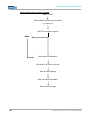
7.2.1
ADDING A RULE SET
Adding a rule set first requires the selection of the layer over the respective Tab (1). In
the Transparent Bridge Mode, filtration on bridged Ethernet interfaces (Layer 2) is
necessary in most cases while in the IP Router Mode or when using the SERVICE modem it
is also possible to choose independent IP interfaces (Layer 3).
Bridged Ethernet interfaces (Layer 2):
Corresponding to the Ethernet filtration level. This setting makes possible, e.g. filtration by
means of Ethernet MAC addresses or network protocols not using IP addresses. Filtration
on the basis of IP protocol features however is also possible.
Independent IP interfaces (Layer 3):
On this level, filtration is only possible on the basis of IP protocol features because
between the interfaces of level 3 only IP data traffic takes place.
Click on the button Add a new rule set (2) to create or add a new or pre-configured rule
for the selected layer. A description of how to create a new rule set is given in the chapters
Define a new rule set on Layer 2 and Define a new rule set on Layer 3. The
chapter Load a pre-configured rule set describes the predefined rule set.
48
© ads-tec GmbH • Raiffeisenstr.14 • 70771 Leinfelden-Echterdingen
IT Infrastructure RAP/RAC1000
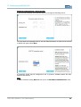
7.2.2
CHANGING AND SEARCHING EXISTING RULE SETS
If you have already created or loaded rules, they appear in the Rules Matrix. If you search
for a rule, you may restrict the filter criteria for the searched rule set by clicking on the
Drop Down boxes From, To (1).
The button Process (2) is used to subsequently change the selected rule set. The selected
rule set is removed by clicking on Delete (3).
Note:
By clicking on the arrows in front of each rule set, detailed information on the selected
rule set is displayed.
© ads-tec GmbH • Raiffeisenstr.14 • 70771 Leinfelden-Echterdingen
49
IT Infrastructure RAP/RAC1000
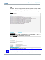
7.2.3
LOADING PRE-CONFIGURED RULE SETS
Select a pre-configured rule set.
The pre-configured rule sets are displayed on the left of the dialogue window.
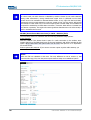
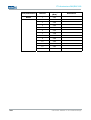
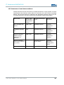
By way of example, the following standard rule sets are pre-configured for layers 2 and 3.
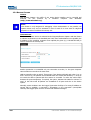
LAYER 2 RULE SETS
Name
Brief Description
ARP
Address Resolution Protocol allows assignment of network addresses
to hardware addresses
Allow_L2
Allows all data traffic on layer 2
Block_L2
Discards all data packets (i.e. blocks all data traffic) on layer 2
ICMP_L2
Allows all ICMP-based data traffic on layer 2
Log_L2
Maintains an event log and discards all data packets on layer 2
Select the rule set you want to load and confirm by clicking Next,
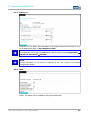
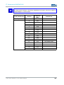
RULE SETS FOR LAYER 3
Name
Brief Description
ALLOW_L3
Allows all data traffic on layer 3
BLOCK_L3
Discards all data packets (i.e. blocks all data traffic) on layer 3
ICMP_L3
Allows all ICMP-based data traffic on layer 3
Log_L3
Maintains an event log and discards all data packets on layer 3
Confirm the next message prompt by clicking Close.
50
© ads-tec GmbH • Raiffeisenstr.14 • 70771 Leinfelden-Echterdingen
IT Infrastructure RAP/RAC1000
Once a rule set has been successfully loaded and activated, it will be shown in the filter
overview page.
© ads-tec GmbH • Raiffeisenstr.14 • 70771 Leinfelden-Echterdingen
51
IT Infrastructure RAP/RAC1000
7.2.4
DEFINITION OF A NEW RULE SET ON LAYER 2
Note:
For configuring rules on layer 3, please refer to the section “Definition of a new Rule
set on Layer 3”.
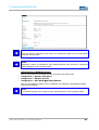
Select the menu item Definition of a new rule set
Enter a name and a description for the new rule set.
Note:
The rule set name is restricted to 10 characters. It is not possible to use umlauts.
Confirm your input by clicking Next.
52
© ads-tec GmbH • Raiffeisenstr.14 • 70771 Leinfelden-Echterdingen
IT Infrastructure RAP/RAC1000
RULE SET LAYERS AND INTERFACES
The following dialogue allows configuration of the type of filtering.
SYMBOL DESCRIPTION
==
Filter will be applied to the selected interface.
!=
Filter will be applied to all interfaces except for the selected interface.
EXAMPLE:
INTERFACE
SELECTION
RESULT
Incoming interface: HOST
==
filters all inbound data packets
on HOST
Outgoing interface: WLAN-1
!=
filters all outgoing data packets
on all ports, except for
WLAN-1
Confirm your input by clicking Next
© ads-tec GmbH • Raiffeisenstr.14 • 70771 Leinfelden-Echterdingen
53
IT Infrastructure RAP/RAC1000
RULE-RELATED MAC ADDRESSES AND MAC PROTOCOLS
Via the following dialogue window it is possible to define the MAC addresses of the
respective sources and targets.
The Source MAC Address defines the source from which data is received.
The Target MAC Address defines the target to which data is sent.
In case you are using a permanent, static connection between two devices, you may enter
their respective MAC addresses here. Otherwise leave the asterisk symbol unchanged.
Note:
If the option “Used Hardware Groups“ is activated, a selection among the added hardware
groups is possible. Use this option if you want to allocate rules for more than one MAC
address.
Note:
If you want to use a permanent connection between two defined devices, you may
define the MAC addresses of the respective devices here.
PROTOCOL
ARP
The Address Resolution Protocol (ARP) is a network protocol that allows
resolving network addresses to hardware addresses. ARP is not an IP-only
or Ethernet-only protocol, but due to the prevalence of IPv4 and Ethernet,
it is used almost exclusively for resolving IP addresses to Ethernet MAC
addresses.
IPv4
IPv4 (Internet Protocol Version 4, formerly simply IP), is the fourth
iteration of the Internet Protocol (IP). It is the first version of the protocol
to be widely deployed and is one of the essential underlying internet
technologies.
Vlan
A Virtual Local Area Network (VLAN) is a virtual local network inside a
physical network. The protocol commonly used in configuring virtual LANs
is IEEE 802.1Q.
Other
54
DESCRIPTION
Allows selection of a different protocol.
© ads-tec GmbH • Raiffeisenstr.14 • 70771 Leinfelden-Echterdingen
IT Infrastructure RAP/RAC1000
Note:
If you do not wish to select a particular protocol, choose the default menu item (i.e. the
asterisk item). Once a specific protocol has been selected you may adjust protocol-specific
configuration settings.
PROTOKOLLOPTIONEN
Folgende Konfigurationsmöglichkeiten bestehen, wenn Sie eines der Protokolle ARP, IPV4,
VLAN oder Other gewählt haben:
The following configuration options are available once a specific protocol has been
selected. In case you have not selected a particular protocol, simply confirm this screen by
clicking Next and follow the steps described in the Rule Name and Behaviour section.
ARP:
ARP offers the following options:
© ads-tec GmbH • Raiffeisenstr.14 • 70771 Leinfelden-Echterdingen
55
IT Infrastructure RAP/RAC1000
IPV4:
IPv4 requires setting a source and a target IP address. Furthermore, the respective subnet
mask for the source and target IP address is required.
The IPV4 protocol allows another comprehensive selection of filter criteria. It is possible to
filter Source IP address, Target IP address, IP protocol, Source and Target Port.
Note:
TCP/UDP ports can be indicated as port ranges, e.g. 80:88 for 80-88, :1024 (all
ports<1024), or 1024: (all ports larger than 1024)
The Internet Protocol offers the following options:
56
© ads-tec GmbH • Raiffeisenstr.14 • 70771 Leinfelden-Echterdingen
IT Infrastructure RAP/RAC1000
VLAN:
The VLAN protocol requires setting a VLAN ID, a VLAN priority and a Wrapped Protocol to
be used.
For the VLAN protocol it is necessary to state the VLAN ID, the VLAN priority and the
packed protocol.
The packed protocol contains a large number of different protocol versions for selection.
You may choose whether you want to use a specific protocol or any but the specific
protocol.
© ads-tec GmbH • Raiffeisenstr.14 • 70771 Leinfelden-Echterdingen
57
IT Infrastructure RAP/RAC1000
OTHER:
Use Other to select the Layer 3 protocol.
Other contains a large number of different protocols for selection. You may choose
whether you want to use a specific protocol or any but the specific protocol.
58
© ads-tec GmbH • Raiffeisenstr.14 • 70771 Leinfelden-Echterdingen
IT Infrastructure RAP/RAC1000
RULE NAME AND BEHAVIOUR:
The next dialogue will allow you to define the rule behaviour in more detail. Use the menu
item Rule Action to determine how the device should handle packets.
Rule Action:
Available options are Allow and Block.
Log:
This function will log any violations of this rule in the event log.
Max. Packets/sec:
Use this option to specify a maximum packet rate per second; this rate will then serve as a
upper limit against Denial-of-Service attacks.
Rule Name:
Choose a name for this rule; the name should be unique, i.e. differ from the name of any
other rule set.
Confirm by clicking Next.
© ads-tec GmbH • Raiffeisenstr.14 • 70771 Leinfelden-Echterdingen
59
IT Infrastructure RAP/RAC1000
OVERVIEW OF ALL RULES IN A RULE SET:
The next dialogue window will provide an overview of all existing rule sets.
Use the Add button for starting the rule configuration process anew to define another rule.
The Edit button allows subsequent modifications to previously defined rules.
Choose Delete to delete the selected rule.
Use the arrow buttons to modify the position of a rule within the current rule set.
Confirm by clicking Save.
Confirm the next message prompt by clicking Close.
Once the rule set was successfully activated, it will be displayed in the filter overview
window.
60
© ads-tec GmbH • Raiffeisenstr.14 • 70771 Leinfelden-Echterdingen
IT Infrastructure RAP/RAC1000
© ads-tec GmbH • Raiffeisenstr.14 • 70771 Leinfelden-Echterdingen
61
IT Infrastructure RAP/RAC1000
7.2.5
DEFINITION OF A NEW RULE SET ON LAYER 3
The configuration of rule sets for filter layer 3 will be described on the following pages.
Note:
If you want to configure Layer 2 after the filter level, use the chapter „Define new rule
set on bridged Ethernet interfaces (Layer 2)“ on the previous pages.
Warning:
Before configuring a rule set on layer 3, ensure the option check box “Activate IP
Router Functionality”, located at the path Basic Settings User Interface. is
checked. Confirm any modifications to this setting by selecting “Activate”.
Select the menu item: Define new rule set.
Click the Add button and subsequently select Definition of a new Rule Set.
Then assign a name and a description to the new rule set.
Note:
Use a different name for each rule set if possible. Do not use umlauts as they will lead to
error messages.
Confirm by clicking Next.
62
© ads-tec GmbH • Raiffeisenstr.14 • 70771 Leinfelden-Echterdingen
IT Infrastructure RAP/RAC1000
RULE SET LAYER AND INTERFACES
The track of the packets is adjusted via the dialogue window, to which this rule set shall be
applied. Both an inbound interface (where the packets come in) and an outbound interface
(where the packets are to leave the device after having been accepted) are required.
Depending on configuration, the following additional interfaces are available on Layer 3:
L3-VPN /Service/IPsec
EXAMPLE:
SYMBOL
INTERFACE
ACTION
==
Incoming interface: HOST
filters all inbound data packets
on HOST
!=
Outgoing interface: WLAN-2
filters
all
outgoing
data
packets on all ports, except
for WLAN-2
Note:
If you do not wish to filter particular ports, choose the default menu item (i.e. the asterisk
item).
Confirm your input by clicking Next.
© ads-tec GmbH • Raiffeisenstr.14 • 70771 Leinfelden-Echterdingen
63
IT Infrastructure RAP/RAC1000
RULE-RELATED INTERNET PROTOCOLS AND IP ADDRESSES
The Source IP Address defines the sender’s address, and the Target IP Address
defines the receiver’s address.
Note:
If the option “Use Network Groups“ is activated, you may choose the added network
groups. Use this option if you want to allocate rules to more than one IP address.
Note:
If you want to use a permanent connection between two defined devices, you may define
the IP addresses of the respective devices here.
Note:
Once a specific protocol has been selected you may adjust protocol-specific configuration
settings.
Internet Protocols:
PROTOCOL
64
DESCRIPTION
TCP
The Transmission Control Protocol (TCP) is a protocol defining the
way in which streams of bytes are exchanged between computers. All
current operating systems support TCP and employ it for exchanging
data with other computers.
UDP
The User Datagram Protocol (UDP) is a minimal message-oriented
network protocol that belongs to the transport layer of the Internet
Protocol Suite. UDP is used to allow application-to-application
communication via the internet.
© ads-tec GmbH • Raiffeisenstr.14 • 70771 Leinfelden-Echterdingen
IT Infrastructure RAP/RAC1000
ICMP
Like TCP and UDP, the Internet Control Message Protocol (ICMP) uses
the Internet Protocol (IP) and is hence also part of the Internet
Protocol Suite. It is chiefly used by networked computers' operating
systems to send error and information messages.
The following overview shows the configuration options available for each protocol.
© ads-tec GmbH • Raiffeisenstr.14 • 70771 Leinfelden-Echterdingen
65
IT Infrastructure RAP/RAC1000
MENU OVERVIEW LAYER 3 SELECTION TCP
Layer 3 TCP
Rule-related Internet Protocol options
e.g. selection:*
UDP/TCP connection control
Auto
Stateless
Stateful
Check rule state settings / bit is set
Rule state settings / bit
is set
Rule name and behaviour
Overview of all rules in rule set
Rule set time settings
Rule set status information
Filter rules start page
66
© ads-tec GmbH • Raiffeisenstr.14 • 70771 Leinfelden-Echterdingen
IT Infrastructure RAP/RAC1000
MENU OVERVIEW LAYER 3 SELECTION UDP
Layer 3 UDP
Rule-related Internet Protocol options
e.g. selection:*
UDP/TCP connection control
Auto
Stateful
Rule state settings / bit is
set
Rule name and behaviour
Overview of all rules in rule set
Rule set time settings
Rule set status information
Filter rules start page
© ads-tec GmbH • Raiffeisenstr.14 • 70771 Leinfelden-Echterdingen
67
IT Infrastructure RAP/RAC1000
MENU OVERVIEW LAYER 3 SELECTION ICMP
Layer 3 ICMP
Rule-related Internet Protocol options
e.g. selection:*
UDP/TCP connection control
Auto
Rule name and behaviour
Overview of all rules in rule set
Rule set time settings
Rule set status information
Filter rules start page
68
© ads-tec GmbH • Raiffeisenstr.14 • 70771 Leinfelden-Echterdingen
IT Infrastructure RAP/RAC1000
EXEMPLARY CONFIGURATION – SELECTION TCP:
If TCP has been selected, the wizard will guide you through the following menus:
You may define source/target ports for TCP and UDP connections. In case you do not wish
to define such ports, select Next.
A connection control may be configured for the TC protocol. Available options are Auto,
Stateless and Stateful.
AUTO
If Auto is selected, clicking Next will take you to the Rule Name and Behaviour menu.
© ads-tec GmbH • Raiffeisenstr.14 • 70771 Leinfelden-Echterdingen
69
IT Infrastructure RAP/RAC1000
STATELESS:
With this option activated, the TCP headers containing information on the connection
status will be analysed.
70
© ads-tec GmbH • Raiffeisenstr.14 • 70771 Leinfelden-Echterdingen
IT Infrastructure RAP/RAC1000
STATEFUL:
The stateful packet filter monitors all session-related connection information.
State Related:
Data packet is assigned to existing data connection, e.g. for
establishing an FTP feedback channel.
State New:
Data packet establishes a new data connection, e.g. TCP with SYN
flag.
State Established:
Data packet belongs directly to specific data connection, e.g. TCP
data without SYN flag.
State Invalid:
Data packets for which the firewall could not determine a valid
connection state.
RULE NAME AND BEHAVIOUR
The action of the rule can be defined in the dialogue window. Under Action for the Rule
menu item, you may specify how the device has to handle a packet. Further, it is possible
to log the events, to release an alarm and to restrict the data throughput.
Confirm your input by clicking Next. Aktion für die Regel:
Zur Auswahl stehen:
Zulassen:
© ads-tec GmbH • Raiffeisenstr.14 • 70771 Leinfelden-Echterdingen
Das Paket wird weitergeleitet.
71
IT Infrastructure RAP/RAC1000
Verwerfen:
Das Paket wird ohne Nachricht an den Absender gelöscht.
Abweisungsgrund:
Hier kann der Abweisungsgrund definiert werden, der dem Absender gemeldet wird.
Log:
Es wird ein Eintrag im Eventlog protokolliert.
Alarm:
Es wird der Alarmausgang gesetzt.
Max.Pakete/Sek:
Hier kann die maximale Paketrate pro Sekunde festgelegt werden, die als Obergrenze
gegen einen Denial-of-Service eingestellt werden kann. Dies ist ebenfalls sinnvoll, um
Regeln die in einem häufigen Intervall einen Eventlogeintrag erzeugen würden, zu
begrenzen
Name der Regel:
Definieren Sie einen eindeutigen Regelnamen. Es ist zwingend notwendig, dass Sie einen
Namen für die Regel des Regelsets vergeben.
Bestätigen Sie mit: Weiter
OVERVIEW OF ALL RULES IN RULE SET
MATRIX OF ALL RULES OF A RULE SET:
The dialogue window displays the various rules of the rule set. The sequence of them can
be changed. Further, the rule set name can be changed.
The set-up process is restarted by clicking on the Add button, and a new rule can be
defined. By means of the Process button, rules already defined can be changed later.
Select Delete to delete the marked rule.
By means of the arrow buttons, the position of a rule within the current rule set can be
changed.
Confirm with Continue
RULE SET TIME SETTINGS
72
© ads-tec GmbH • Raiffeisenstr.14 • 70771 Leinfelden-Echterdingen
IT Infrastructure RAP/RAC1000
Note:
If the validity is restricted, there must be stated at least one weekday, otherwise the rule
will be invalid and not be used
Note:
Irrespective of the time zone configuration of the device, the validity periods must be
configured in consideration of the UTC time!
Complete the configuration by clicking Save.
Confirm the next message prompt by clicking Close.
© ads-tec GmbH • Raiffeisenstr.14 • 70771 Leinfelden-Echterdingen
73
IT Infrastructure RAP/RAC1000
Once a rule set has been successfully loaded and activated, it will be shown in the filter
overview page.
This completes the first-time configuration using the configuration wizards.
74
© ads-tec GmbH • Raiffeisenstr.14 • 70771 Leinfelden-Echterdingen
IT Infrastructure RAP/RAC1000
8
ACCESS POINT/CLIENT WEB INTERFACE
The Access Point Web Interface is structured in five main menu items.
DIAGNOSTICS
Shows the current interface status
CONFIGURATION
Configures the Access Point specific functions
SYSTEM
Allows basic settings and changes in the web interface
INFORMATION
Contains general information with respect to this device
8.1
DIAGNOSTICS MAIN MENU ITEM
8.1.1
SYSTEM STATUS
The web interface start page shows all important Access Point settings at a glance.
Functions can be selected directly via hyperlinks from the start page.
© ads-tec GmbH • Raiffeisenstr.14 • 70771 Leinfelden-Echterdingen
75
IT Infrastructure RAP/RAC1000
8.2
76
GENERAL OVERVIEW FOR CONFIGURATION IN THE MENUS
© ads-tec GmbH • Raiffeisenstr.14 • 70771 Leinfelden-Echterdingen
IT Infrastructure RAP/RAC1000
8.2.1
IP ROUTING EXEMPLARY CONFIGURATION
This example shows, by means of the IP routing menu item, how a setting is made and
stored. Furthermore it explains how a certain setting is disabled or deleted.
Note:
If you don't know exactly, which setting is the correct one in a specific selection / input
box, you can put the mouse pointer on the question mark right next to this selection. A
tooltip box will appear, giving you some advice and explanation, including some
examples.
SELECTION 1
Make a selection in the pull down menu first. Click on the arrow next to the setting in order
to make a selection.
SELECTION 2
Subsequently, enter all user specific settings in the input boxes.
SELECTION 3
Confirm your entry by clicking on "Add entry". Your settings will now be stored.
Your settings are stored and enabled now. (Tick at no. 1)
© ads-tec GmbH • Raiffeisenstr.14 • 70771 Leinfelden-Echterdingen
77
IT Infrastructure RAP/RAC1000
SELECTION 1
Remove the tick at no. 1 and select "Apply settings" if you want to disable a currently
enabled setting. This setting is disabled now.
SELECTION 2
Tick the box at no. 2 and select "Apply settings" in order to delete a certain setting.
Note:
The "Reset changes" button in the task bar allows to reset settings you made earlier to
the default value.
78
© ads-tec GmbH • Raiffeisenstr.14 • 70771 Leinfelden-Echterdingen
IT Infrastructure RAP/RAC1000
8.2.2
ERROR MESSAGES
The firewall identifies wrong entries by highlighting the affected input box in red.
Note:
By means of the exclamation mark next to the wrong entry you can identify what the
reason for this error might be, or which values might be required.
© ads-tec GmbH • Raiffeisenstr.14 • 70771 Leinfelden-Echterdingen
79
IT Infrastructure RAP/RAC1000
8.2.3
EVENTLOG
STATE
The Eventlog represents the most important diagnostics tool of this device and contains
essential information about the system status. Potential system error messages will be
entered and displayed here. The Eventlog display acts like a protocol and records all
system activities. In the Eventlog, you can view changes in settings and error messages as
a protocol.
CONFIGURATION
The Eventlog protocol can also conveniently be sent to a central computer. In order to do
this, the remote computer will be entered in the input boxes.
Additionally, syslog messages can be sent by email. To do this, specify the IP-address of
your E-mail server and a receiver E-mail address.
Note:
In order to avoid high data volumes due to emails, a suitable threshold value should be
entered in the Line threshold box. The Line threshold specifies the number of lines which
will be sent together in one email if the threshold value is reached.
80
© ads-tec GmbH • Raiffeisenstr.14 • 70771 Leinfelden-Echterdingen
IT Infrastructure RAP/RAC1000
8.2.4
ICS-STATUS
The menu item ICS Status gives information on all neighbouring network structures. They
can be displayed in detail via Own Neighbour Table.
Note:
To activate the ICS function, the ICS setting must be activated under Configuration
WLAN-1/2-Parameters Channel
Note:
Further information on the mode of operation of the ICS is given in the WLAN
Configuration chapter.
8.2.5
HOST
Based on the data, how the packets have been received or sent, can be traced back
exactly. The display can be updated by using the Reload button.
© ads-tec GmbH • Raiffeisenstr.14 • 70771 Leinfelden-Echterdingen
81
IT Infrastructure RAP/RAC1000
8.2.6
PING TEST
By using the Ping test option you can check if a connected remote station can be reached
or not. The Ping test sends an echo request packet to the destination address of the
remote station to be tested and evaluates the test information.
Please enter the destination address to be tested in form of an IP-address in the
designated box. Additionally, the Number of ping messages to be sent must be specified. It
is limited to 10 packets.
By clicking on the Apply settings button the ping test will start.
After a short time an overview will appear which shows the ping test process steps and
result. The overview indicates both the sent and the received packet status.
The Ping test is finished by pressing the Continue button.
82
© ads-tec GmbH • Raiffeisenstr.14 • 70771 Leinfelden-Echterdingen
IT Infrastructure RAP/RAC1000
8.2.7
REMOTE CAPTURE
With Remote Capture the data packets can be recorded for the individual interfaces of the
access point for diagnostic purposes. Therefore it is necessary to use the tool "Wireshark"
on Windows. Additionally, it is possible to set the wireless interfaces into the monitor mode
to record 802.11 level packages with the tool Radiotap header.
8.3
MAIN MENU ITEM CONFIGURATION
8.3.1
IP CONFIGURATION
The IP configuration of the Access Point.
Note:
The question mark to the right of the pull down menu provides you with advice and
brief explanations for the menu items available for selection.
Static:
If this option is selected, a permanently assigned IP address may be entered.
Static IP-address assignment requires that the IP address and the subnet mask is entered.
The default values are:
IP address:
192.168.0.254
© ads-tec GmbH • Raiffeisenstr.14 • 70771 Leinfelden-Echterdingen
83
IT Infrastructure RAP/RAC1000
Subnet mask:
255.255.255.0
DHCP:
The DHCP function requests an IP address from a DHCP server and assigns it automatically
to the Access Point.
DHCP with fallback address:
This option is a combination of static and automatic IP-address assignment. If an error
occurs during automatic address assignment of the DHCP server, or if no DHCP server is
available, IP assignment automatically switches to the entered static IP address.
Activate Spanning Tree Protocol:
The spanning tree protocol is used for avoiding loops in particular in network environments
with switching.
With this function activated, redundant network lines can be generated.
Default gateway:
In this option, you can specify the IP address of the gateway to be used.
The IP address of this default gateway is used by the device for setting up an IP
configuration for an address outside of its own IP subnet (outside of 192.168.0.254 in this
example). The IP address, however, must be within the range of this network. Its value
will probably be overwritten by a dynamic DHCP value if DHCP was configured under IP
assignment, and if the DHCP server supports this option. The default gateway might be
required e.g. in order to reach an NTP time server, or in order to forward the IP address to
WLAN clients in case of a DHCP setup.
84
© ads-tec GmbH • Raiffeisenstr.14 • 70771 Leinfelden-Echterdingen
IT Infrastructure RAP/RAC1000
IP ROUTER
The IP router option divides the networks in two separate networks between LAN-in and
LAN-out interface and filters them separately.
WLAN / Host interface:
IP assignment for the LAN-in interface can be made in two different ways:
Static:
If this option is selected, a permanently assigned IP address may be entered.
Static IP-address assignment requires that the IP address and the subnet mask is entered.
The default values are:
IP address:
192.168.0.254
Subnet mask: 255.255.255.0
DHCP:
The DHCP function requests an IP address from a DHCP server and assigns it automatically
to the firewall.
DHCP with fallback address:
This option is a combination of static and automatic IP-address assignment. If an error
occurs during automatic address assignment of the DHCP server, or if no DHCP server is
available, IP assignment automatically switches to the entered static IP address.
© ads-tec GmbH • Raiffeisenstr.14 • 70771 Leinfelden-Echterdingen
85
IT Infrastructure RAP/RAC1000
Activate Spanning Tree Protocol:
The spanning tree protocol is used for avoiding loops in particular in network environments
with switching. With this function activated, redundant network lines can be generated.
Activate NAT on:
By enabling the Network Address Translation (NAT) option on the selected interface, a
private IP address range is masked with a global IP address. Activating NAT is
recommended with DSL connections.
Standard gateway:
In this option, you can specify the IP address of the used gateway.
Click subsequently on Apply settings.
Now your changes are activated.
Hinweis:
Die
folgenden
Konfigurationsmöglichkeiten
Ausstattungsvariante vorhanden.
86
sind
nur
bei
entsprechender
© ads-tec GmbH • Raiffeisenstr.14 • 70771 Leinfelden-Echterdingen
IT Infrastructure RAP/RAC1000
IP CONFIGURATION (RAC15XX)
The RAC15xx device is equipped with an integrated switch, which may be configured in the
IP configuration.
© ads-tec GmbH • Raiffeisenstr.14 • 70771 Leinfelden-Echterdingen
87
IT Infrastructure RAP/RAC1000
EXTENDED BACKROUND SCANNING (RAC112X)
The RAC112x device now supports the Extended background scanning mode. In this
mode, the WLAN2 interface is exclusively used for permanently scanning for new Access
Points. As soon as a better Access Point was found, the WLAN1 interface books in on the
new AP. All parameters for WLAN2 are disabled in this mode.
This mode is specifically suited for fast roaming in connection with Access Points of other
manufacturers. In particular, the Multi client bridge mode can be combined with the
Extended background scanning mode.
88
© ads-tec GmbH • Raiffeisenstr.14 • 70771 Leinfelden-Echterdingen
IT Infrastructure RAP/RAC1000
EXTENDED BACKROUND SCANNING & IP-ROUTER (RAC112X)
In this mode, WLAN-1 and HOST can be provided with their own IP addresses. The WLAN2 interface is automatically used as Background Scanning interface.
Note:
The operation mode is explicitly for WHOST infrastructures with Access Points which are
not from ads-tec, and in particular for setups with Switched WLAN or WLAN Controller.
© ads-tec GmbH • Raiffeisenstr.14 • 70771 Leinfelden-Echterdingen
89
IT Infrastructure RAP/RAC1000
8.3.2
WLAN-1 PARAMETER
Using this menu, the Access Point interfaces can be set up. All interfaces have their own
setup options, which have an impact on how the interface works. Additionally, unused
interfaces may be disabled.
Note:
Depending on the equipment version of the device, 2 WLAN interfaces might be available.
WLAN1 (ACCESS POINT) 2.4GHZ-802.11B/G:
The checkbox next to Enable interface must be ticked so that changes and settings can be
made with respect to the interface.
Operational mode: Switching / Selection: Access Point / Client (this option is not available
on the RAC111x or RAC151x model.
Hide SSID: The SSID (network name) will not be displayed with this function enabled.
Network name (SSID): Name of the network. Default setting: ads. The SSID may contain
up to 32 characters.
Note:
Valid characters are: a-z, A-Z, 0-9 and the special characters: . _ - ? $ @ ! { } [ ] ( ) + #
;,<>|:*~%$&/=
90
© ads-tec GmbH • Raiffeisenstr.14 • 70771 Leinfelden-Echterdingen
IT Infrastructure RAP/RAC1000
WLAN mode: Selection of a specific WLAN mode
Channel: Offers the opportunity of either selecting a specific channel or the automatic
channel search function.
Note:
If the Intelligent Channel Selection (ICS) function is active, all ads-tec Access Points
in a local Ethernet segment are interlocked and optimize their channel selection on the
basis of different parameters. Here both the signal propagation ratios between the
devices are recorded and measured and other interfering Access Points outside the
network are taken into consideration. An ads-tec Access Point starts ICS measurement
during the booting process if the option is activated for the first time or the Remeasure
Timer has expired (visible by alternately flashing (red/green) LEDs on HOST port). The
measuring phase takes ~100 seconds. During this time, WLAN Clients cannot login at the
AP. If 5Ghz are configured with the DFS, the time up to readiness is extended to ~160
seconds.
Transmit rate: Allows manual or automatic setup of the Mbit rate.
CTS/RTS threshold: A signal is transmitted to the Access Point if a packet to be transmitted
has a size which exceeds the value setup in this item. The Access Point then reserves the
channel for this packet.
Fragmentation threshold: If a packet exceeds the value set up in this item, the packet will
be fragmented and divided into smaller packet units.
Note:
This fragmentation threshold cannot be used with the WPA encryption standard turned
on.
Longdistance:
If a large distance must be overcome between 2 devices the timeout for specifying the
distance may be increased here. The longer timeout setting causes the Access Point to
wait longer for proper reception of a response from the remote terminal.
Transmission antenna:
By selecting the transmission antenna you can decide if the transmission antenna should
be selected automatically or set up manually.
Antenna gain: The antenna gain can be used in order to gain higher transmission power.
Furthermore, it is limited by valid regulations of the respective country.
Example: An antenna with the value of 10dbi and a cable with the value of 3 db are used.
The value for the antenna amplification in this case amounts to 7dbi.
Power constraint:
The power constraint limits the Access Point power to the indicated value. The value
entered here is transmitted to all clients having access to the Access Point.
© ads-tec GmbH • Raiffeisenstr.14 • 70771 Leinfelden-Echterdingen
91
IT Infrastructure RAP/RAC1000
STATE
View: Access Point
The state display of the WLAN-1 interface shows data traffic characteristics. The display
can be updated by using the Reload button.
92
© ads-tec GmbH • Raiffeisenstr.14 • 70771 Leinfelden-Echterdingen
IT Infrastructure RAP/RAC1000
WLAN-1 (ACCESS CLIENT) 2.4 GHZ – 802.11B/G:
The client option is only distinguished in two points: the "Hide SSID" option is missing and
there is one new option, the "Use fixed Access Point BSSID":
© ads-tec GmbH • Raiffeisenstr.14 • 70771 Leinfelden-Echterdingen
93
IT Infrastructure RAP/RAC1000
Use fixed Access Point BSSID:
If this option is enabled, you can enter the MAC address of an Access Point. This option is
helpful with Access Points sharing the same SSID, because the respective device can still
individually be addressed.
Confirm this action subsequently with Apply settings.
STATE
Access client view:
The state display of the WLAN-1 interface shows data traffic characteristics. The display
can be updated by using the Reload button.
94
© ads-tec GmbH • Raiffeisenstr.14 • 70771 Leinfelden-Echterdingen
IT Infrastructure RAP/RAC1000
WLAN1 (ACCESS POINT & ACCESS CLIENT) 5 GHZ – 802.11A (ETSI):
If the WLAN 802.11a mode or in case of the client, the 802.11a/b/g mode is configured,
the following options change:
Hinweis:
The Option „Outdoor“ is just available in Access Point Mode. The Option „Deactivate DFS“
is available in both Modes.
Outdoor:
Must be enabled if the Access Point is part of a radio connection in the outdoor area.
Certain channels of the 5GHz band may not be used outdoors, and will be excluded by this
option. This option is of no importance for Access Clients.
Disable DFS:
You may disable DFS if the Access Point is NOT used outdoors. You may also manually set
up channels 36, 40, 44 and 48 as fixed channels, in this case. Additionally, the permissible
maximum output power is reduced. In client mode, in contrast to that, DFS may also be
disabled for outdoor use.
Use 5.6 Ghz Channels:
The channels 120.124 and 128 will be activated. When the DFS function is enabled, a
response time (Channel Availability Check Time) of 10 minutes must be observed.
© ads-tec GmbH • Raiffeisenstr.14 • 70771 Leinfelden-Echterdingen
95
IT Infrastructure RAP/RAC1000
Note:
In client mode, the DFS function is disabled by default. Caused by the radar detection
during data transmission, strong interferences might occur in particular at the client,
which have to be evaluated as Potential Radar Pulses. A very high CPU load and faulty,
frequently occurring radar detection cycles are results of that. For this reason, DFS should
be enabled in client mode only if the client output power exceeds 23dB, and if 30dBm are
required for establishing a stable data connection. If another 5GHz device is located near
the device in question, this might also cause significant disturbances to the client mode, if
DFS is activated there as well.
WLAN1 (ACCESS POINT & ACCESS CLIENT) 2.4 GHZ – 802.11A (FCC):
The FCC setup version for interfaces has the following additional setup options:
Indoor/Outdoor:
Must be enabled if the Access Point is part of a radio connection in the outdoor area.
Certain channels of the 5GHz band may not be used outdoors, and will be excluded by this
option. When used indoors the option indoor can be used. This option is of no importance
for Access Clients.
Point-to-point radio antenna: If you want to connect a point-to-point radio antenna, you
must activate this checkbox.
Note:
DFS and TPC are disabled in this case. The only difference to the A version is, that
version 802.11b/g (FCC) has the point-to-point antenna setup as an additional option.
96
© ads-tec GmbH • Raiffeisenstr.14 • 70771 Leinfelden-Echterdingen
IT Infrastructure RAP/RAC1000
MONITOR
In monitor mode data packets can be recorded an transferred to a PC.
Note:
This function will only work in combination with Remote Capture..
Enable channel hopping:
If the function is enabled all available channels will be passed and records packages for the
set time.
© ads-tec GmbH • Raiffeisenstr.14 • 70771 Leinfelden-Echterdingen
97
IT Infrastructure RAP/RAC1000
8.4
WLAN-1 SECURITY
WLAN 1 / 2
The WLAN Security settings allow configuring the corresponding security standards for the
WLAN network. The following modes are available for selection:
98
© ads-tec GmbH • Raiffeisenstr.14 • 70771 Leinfelden-Echterdingen
IT Infrastructure RAP/RAC1000
WEP 64 BITS / WEP 128 BITS
A preshared key, which controls access to the WLAN network, is used in the WPA settings
with the WEP 64 bits / 128 bits mode. The difference is that this key cannot be changed in
WEP mode, but remains a static key.
AUTHENTICATION TYPE:
Automatic:
The Automatic mode automatically selects the authentication type.
Open System:
The Open System authentication type is the default authentication setting.
Shared Key:
The Shared Key authentication type is using an extended handshake mechanism for
logging in, which however, does not provide additional security.
Key encoding:
ASCII or HEX may be used as key encoding types. ASCII is a 7-bit, and HEX is a 16-bit
encoding system.
WEP key:
The WEP key is restricted to 5 characters if ASCII is selected. HEX allows entering a 10digit WEP key. No words, but combinations of letters and numbers should be used when
choosing the key.
© ads-tec GmbH • Raiffeisenstr.14 • 70771 Leinfelden-Echterdingen
99
IT Infrastructure RAP/RAC1000
WPA/PSK
A key in combination with a specific encryption method is used in the WKA/PSK mode. The
key (preshared key) must have between 8 and 63 characters. It is recommended to
choose not words but combinations of letters and numbers in order to ensure an optimum
in security.
Encryption algorithm:
It is possible to either use all encryption algorithms or a specific encryption algorithm. You
have to consider here, that the WPA 2 standard must be supported by all devices in order
to ensure proper function.
100
© ads-tec GmbH • Raiffeisenstr.14 • 70771 Leinfelden-Echterdingen
IT Infrastructure RAP/RAC1000
WPA RADIUS SERVER
The Access Point is capable of using an existing Radius server for account authentication.
For this option, the Radius server IP-address must be entered in the IP address box.
The TCP port, on which the Radius server is operated, must be entered under TCP port,
too. Usually, the radius server runs on TCP port 1812.
Using the Radius shared secret, the Access Point will be identified and authenticated at the
radius server.
If two radius servers are used, another configuration may be entered under Secondary, as
an alternative. This specification only comes into effect if the Primary radius server
previously could not be reached. The Access Point will then try to establish a connection to
the Secondary radius server. Confirm this action with Apply settings.
© ads-tec GmbH • Raiffeisenstr.14 • 70771 Leinfelden-Echterdingen
101
IT Infrastructure RAP/RAC1000
8.5
STATIC MAC ADDRESS
The static MAC filter can be used in order to provide an interface, which has been
configured as an Access Point, with an access control capability. In this case, the MAC
address of a WLAN client is checked against the access list configured, and access will be
granted according to that. If access for a client is barred, the client will be rejected when
attempting to log in with the 802.11 protocol. This configuration, however, does not
provide very high security levels because the MAC address can easily be forged. In case of
WPA encryption, this method is not useful because WPA itself already offers sufficient
security. A MAC filter as an additional protective method would only make sense in
connection with WEP encryption. If an interface is not included in the Access Point mode,
the filter table cannot be used. The text "No wlan interface in AP mode, filter is inactive"
will appear. This menu item does not exist with RAC111x and RAC151x.
Default policy:
The default policy defines what should be done with a MAC address in the filter table. A
client can explicitly be locked out (Blacklist) or permitted (Whitelist). The last option is the
setting used in most cases.
Syslog:
If this option is set, a message will be generated in the Eventlog if a client is rejected,
because the client is explicitly locked out or not permitted.
Add new filter:
The MAC address of the client must be specified e.g. in the 00:50:C2:48:A1:BB format,
and the interfaces on which this entry should be valid, must be specified, in order to create
a new filter table entry (WLAN-1, WLAN-2, *). The options "Active" or "Inactive" can be
selected under "Action" in order to temporarily deactivate an entry or to activate this entry
not immediately. Subsequently you have to click on "Add entry".
102
© ads-tec GmbH • Raiffeisenstr.14 • 70771 Leinfelden-Echterdingen
IT Infrastructure RAP/RAC1000
Add mac list file:
If multiple MAC addresses should be configured at once, it can be useful to use a text file
including a list of all MAC addresses. Such a file will contain one MAC address per line, e.g.
00:50:C2:48:A1:00
00:50:C2:48:A1:02
00:50:C2:48:A1:01
Additionally, you'd have to select if the MAC addresses loaded in this way are supposed to
be "Active" or "Inactive", and on which interface they should be valid. This list will be
added to the existing entries. A maximum of 500 entries may be stored.
Note:
If this list is very long, processing might take a long time; you'd have to expect
approximately 1 second per entry. This period will then also be required for booting when
the settings are loaded.
© ads-tec GmbH • Raiffeisenstr.14 • 70771 Leinfelden-Echterdingen
103
IT Infrastructure RAP/RAC1000
8.6
FILTER WIZARD
Note:
The Filter wizard may also be started using the start page of the Web interface.
The filter wizard supports you in creating rules in such way that a step-by-step user
interface automatically creates prompts for the most frequently used configuration
parameters of rules.
Note:
Rules will be processed in the order of the list. If a rule is true, then processing for this
packet will be finished.
A rule set is only considered for a packet if the „in/outbound“ interface setting matches
the packet.
When running through a rule set, the rules contained in the set are run through from top
to bottom.
Once a rule matches exactly with the packet in a running rule set, the related action will
be executed and no other rule be checked.
Each rule set may contain up to 10 rules whereas all rules of a rule set must have the
same configuration with regard to the respective inbound or outbound interface. The
active Layer 2 rule sets are displayed on the main page of the packet filter.
The rule sets displayed on the basis of inbound and outbound interfaces can be restricted
by means of a filter function at the end of the page. This has no impact on the
functionality of the rules, i.e. non-displayed rules are nevertheless active.
New rule sets can be added by means of the toolbar above the filter function for inbound
and outbound interfaces. By clicking on the plus symbol, a dialogue will appear leading the
user step by step through the setting options of the various log levels.
In the operation mode of Extended IP Router with selected Layer 2 level, only Open VPN
interfaces can be filtered. The Layer 3 level allows filtration of all interfaces with an IP
address in any direction.
Only those rule sets appear in the list for which the inbound and outbound interfaces and
the communication direction match.
104
© ads-tec GmbH • Raiffeisenstr.14 • 70771 Leinfelden-Echterdingen
IT Infrastructure RAP/RAC1000
Note:
After defining the rules, the button Apply changes in the web interface must be activated
for testing this function.
8.7
BASIC SETTINGS
SYSTEM DATA
Important data such as the location and service addresses may be stored by using the
System data user box. This information is used for unambiguous identification of the
device at its location and of the corresponding contact data, which you can view here in a
service case.
Serial no. as system name:
This option is activated by default and displays the systemname and the serial number of
the device.
For confirming the settings you made, please click on Apply settings.
© ads-tec GmbH • Raiffeisenstr.14 • 70771 Leinfelden-Echterdingen
105
IT Infrastructure RAP/RAC1000
DATE & TIME
Date and time can be configured via Date & Time.
The device is not equipped with a Real Time Clock. Therefore, settings are reset to the last
saved values after a power failure.
The time is automatically synchronized by activation and input of the IP address of the NTP
server.
Time zone:
The correct time zone is set in the Drop Down menu.
Daily saving of current time:
If the option is ticked, the current system time will be saved.
Activate time synchronization with timer server (NTP):
The function allows for synchronization of date and time by means of three different NTP
servers. Once an NTP server responds successfully, this one will be used.
For this purpose activate the checkbox next to the option and enter the IP address of the
NTP server.
Manual setting of date & time:
Here the current date and time can be set manually.
For taking over changes, click on Activate.
Hinweis:
Date and time settings are important for the creation of certificates, the evaluation of
event log entries and for time-based rules. Without activated NTP server, the current time
gets lost after a power failure, i.e. it has to be reset manually
106
© ads-tec GmbH • Raiffeisenstr.14 • 70771 Leinfelden-Echterdingen
IT Infrastructure RAP/RAC1000
USER INTERFACE
In the "User interface" menu, you can set the web interface language to German or
English.
In the pull down menu, you can choose from the options "Apply immediately & do not
save" or "Save only & do not apply".
The "Apply immediately & do not save" function shows an "Apply settings" button on
all pages in the Access Point menu, by means of which the changes made may
immediately be applied. Settings must be saved by clicking on the flashing floppy disk icon
now, in order to retain this new configuration even after restarting.
The "Save only & do not apply" function shows a "Save settings" button on all pages in
the Access Point menu. Changed settings will not be applied, but immediately saved
instead.
The "Please wait" dialogue shown when transmitting a page is not applicable here.
Instead of the floppy-disk icon, a restart icon, which brings you back to the start page
where you can perform a restart, will flash now.
Exceptional cases, for which the "Please wait" screen is displayed, are specific actions
like the ping test or firmware updates.
Confirm your settings by pushing Apply settings.
© ads-tec GmbH • Raiffeisenstr.14 • 70771 Leinfelden-Echterdingen
107
IT Infrastructure RAP/RAC1000
CERTIFICATES
Access Point certificates are for authentication in respect of L2TP/IPSec, OpenVPN and the
HTTPS Web server. On this web page of the Access Point certificate management, some
demo certificates have already been filed just for test purposes.
If a certificate is uploaded, its validity will be checked automatically. An invalid certificate
the time and date range of which, for example, does not agree with the system time of the
Access Point, will be displayed in the validity column as invalid. Hereupon, a question mark
appears in relation to the invalid certificate via which further information on the system
error message can be retrieved in the English language.
CRL-CERTIFICATES:
The CRL status of a certificate is indicated in the top line:
Individual certificates can appear as invalid if a certificate has been revoked by means of
the CRL.
Hinweis:
A Client‘s certificate file must contain both a private key and a public part of
certificates. The private key must be available in the RSA format.
Click on Activate to save your settings.
108
© ads-tec GmbH • Raiffeisenstr.14 • 70771 Leinfelden-Echterdingen
IT Infrastructure RAP/RAC1000
SCEP:
Allowing the use of an SCEP Certificate Service (e.g. Windows 2008 Server).
When this function is used, a certificate is automatically allocated to the device.
STATUS
Visualizes the certificate updating process.
© ads-tec GmbH • Raiffeisenstr.14 • 70771 Leinfelden-Echterdingen
109
IT Infrastructure RAP/RAC1000
8.7.1
ACCESS AUTHORIZATION
USER ACCOUNTS
The users of the device can be filed via the user accounts and be configured according to
their authorization.
User accounts
Enlisting currently configured user accounts. It is possible to deactivate the user accounts
or to delete them completely.
By activation of the guest account, the user may view all settings of the device but he
cannot change them.
If the guest account is activated without setting a new password, use the password
Guest. When the guest password is set for the first time, Guest shall also be used as Old
password.
Changing password
The password of the respective user account can be changed under Change password.
The password defined hereunder is queried when the web interface is started by the
browser. To change an already existing password, enter the current password in the box
Old password. Choose a new password and confirm this again in the box Password
Confirmation.
The predefined user admin, which cannot be deleted or activated, may as only user
change the password of other users without having to enter an old password.
New user account
Allowing for the creation of a new user account. A user name and password must be
defined. Click on Activate to create the account.
Note:
The menu item User Accounts just serves the purpose of Account Management.
Authorization for a user account is given under menu item Variable Rights.
110
© ads-tec GmbH • Raiffeisenstr.14 • 70771 Leinfelden-Echterdingen
IT Infrastructure RAP/RAC1000
Note:
A newly created user account must be activated via the checkbox „Account
active“.
Changing the account:
To change between accounts, use the link User:xxxx at the end of the navigation bar.
Now enter the required data for the account to be changed. Afterwards the new account
will be active.
Note:
This link can also be used to logout from the web interface. Confirm with Cancel in the
next following dialogue window.
Note:
The chosen password must have 4-20 characters. Valid characters are: 0-9, A-Z, a-z, and
„-._# /@“.
Note:
If you have used the browser-specific option “Save Password“, it is possible that you can’t
logout properly via this link. In this case deactivate the setting in your browser or select the
respective option in your browser to delete the active authentication.
© ads-tec GmbH • Raiffeisenstr.14 • 70771 Leinfelden-Echterdingen
111
IT Infrastructure RAP/RAC1000
PERMISSIONS
Via Permissions, newly created user accounts can be granted appropriate writing rights,
such as writing access to certain fields. As an example, the user account Test was created
that is now to be configured accordingly.
Each setting can be opened by one click. Use the checkbox of the various settings to
define in which fields writing rights are to be granted.
All settings made must be confirmed by Activate.
To create an additional admin account with the same features as the default admin
account, click on the checkbox „Writing Access Standard Setting. In one point
however this admin account differs from the user „admin“: only the user „admin“ may
change the password of other users without knowing the old password. If you use the
option „Writing Access Standard Setting“, you may setup exceptions from these
writing rights by deleting them under individual variable rights in the selection box.
112
© ads-tec GmbH • Raiffeisenstr.14 • 70771 Leinfelden-Echterdingen
IT Infrastructure RAP/RAC1000
WEB ACCESS
The Web Interface Access Control allows setting the access via HTTP and HTTPS at
the available HOST or HOST interface, depending on the operation mode. Further, it is
possible to set whether access violations shall be reported via the event log
(View of Transparent Bridge)
To deny access, remove the checkmark of the respective option.
Confirm your changes by clicking on Activate.
© ads-tec GmbH • Raiffeisenstr.14 • 70771 Leinfelden-Echterdingen
113
IT Infrastructure RAP/RAC1000
8.7.2
ADV. WLAN
IAPP
IAPP is used for exchanging control and additional information between Access Points
(APs). An AP, for instance sends an IAPP notification to all other APs in the network if a
client logs in. Then, as a result, all other APs can remove this client from their table of
logged in clients. The LLC Xid packets, also originally defined in IAPP, are always
transmitted if a client logs in, independent on this setting.
Enable IAPP
Enables IAPP broadcasts and receiving of IAPP messages on APs.
Enable IAPP client update
Enables a specific ads-tec extension of the IAPP protocol. In this case, 802.11 beacon data
will additionally be sent as an IAPP broadcast via Ethernet in 1 second intervals. Ads-tec
clients are able to receive this information and will in this way learn the state and the
current channel of all APs, even if they might not be visible per radio yet. This information
is primarily required for fast roaming processes in order to automatically process the
channel resolution in the 5 GHz band. Therefore, this option is only useful if fast roaming is
applied.
Note:
The IAPP (Internet Access Point Protocol) was incomplete when it was defined as 802.11f
by the IEEE; this draft was later withdrawn. As a result, IAPP is no standardised protocol.
114
© ads-tec GmbH • Raiffeisenstr.14 • 70771 Leinfelden-Echterdingen
IT Infrastructure RAP/RAC1000
ROAMING WLAN-1
General info about roaming:
Roaming is always used in those cases where the client moves around in a large area,
covered by more than one Access Point. Compared with point-to-point radio links and
other PPP connections, which in most cases have a fixed channel selection, clients must be
able to find several access points on different channels in case of a roaming setup. Settings
on this page allow specifying the transition from one to another network for trouble-free
and optimised function.
SNR roaming threshold (dB):
This threshold specifies, starting from which dB value roaming is initiated. As soon as the
dB value falls short of the value specified, the roaming process will start.
Number of packets below threshold:
Specifies the quantity of packages for the underflow of the value.
SNR neighbour roaming trigger value:
The client is also processing packets from other Access Points on the same or on
neighbour channels.
Roaming with such an Access Point will be initiated as soon as
packets are received, the SNR value of which is better.
Note:
A more detailed description for optimised roaming function configuration is shown in the
"Advanced roaming parameters" application example.
© ads-tec GmbH • Raiffeisenstr.14 • 70771 Leinfelden-Echterdingen
115
IT Infrastructure RAP/RAC1000
FAST RAOMING
The Fast roaming function allows a specific log-in to an existing Access Point without
initiating a scanning process.
Roaming list:
The roaming list contains all Access Points to which a connection is to be established. The
list will be processed in the given order. The first entry is used for the first connection
attempt.
Modbus/TCP roaming control:
Enables the clients Modbus/TCP API. A PLC can then retrieve the current position in the
roaming list or can initiate fast roaming to any entry in the roaming list.
Add new entry to Roaming List:
Allows entering an Access Point in the roaming list. The MAC address of this Access Point is
required to enter. Furthermore, the channel (1-13) on which the Access Point can be
reached may be entered. If the channel is unknown, you may select the Auto option.
The Fast roaming page also supports Access Points (Aps) of other manufacturers. This will
be continued, and is even required for processing dynamic channels, in particular in the 5
GHz band and including DFS. The APs channel may statically be preset on 2.4 GHz or with
5 GHz with the DFS option disabled. The client will then only process these APs in the
given order and with the given roaming thresholds. If the device cannot jump to a certain
AP, the device will go in default scan mode, and the remaining roaming parameters, like
e.g. the "Disabled channels", will be enabled.
116
© ads-tec GmbH • Raiffeisenstr.14 • 70771 Leinfelden-Echterdingen
IT Infrastructure RAP/RAC1000
802.11H WLAN-1
The 802.11h standard defines an extension of the IEEE 802.11 WLAN standard in order to
allow communication on the 5 GHz band according to the regulation in Europe. The
standard contains two components: DFS: (Dynamic Frequency Selection) and TPC
(Transmission Power Control). DFS is already configured on the Standard WLAN page.
ENABLE TPC:
Transmission Power Control aims at reducing the transmission power of a device as much
as possible. TPC is always activated if a 5 GHz channel is used; TPC cannot be switched off
in this case. In the 2.4 GHz band, TPC is not active by default, but may be enabled if
desired.
Select TPC profile:
• Standard: Optimises transmission power for a data rate of 48 Mbit/sec.
• Max. Power: Optimises transmission power for a data rate of 54 Mbit/sec.
• Min. Power: Optimises transmission power for a data rate of 11/12 Mbit/sec.
Select TPC refresh rate:
Fast moving clients should use a high refresh rate, or the connection might be terminated.
The low rate may be used for static connections.
24h scan start time:
DFS requires to disable the WLAN every 24h and to search the available channels for radar
signals for at least one minute. In order to avoid that this required downtime falls into a
critical time of the day, you can select the point in time when the 24h scan should be
carried out.
Note:
This DFS option is not available with FCC.
© ads-tec GmbH • Raiffeisenstr.14 • 70771 Leinfelden-Echterdingen
117
IT Infrastructure RAP/RAC1000
8.7.3
SONSTIGES
Re-measure Interval:
The Re-measure Interval indicates when a device shall re-measure its surrounding. The
measurement is only performed when no Client is logged in. If a Client is logged in, a new
trial is started after Retry Interval seconds. During measurement, the AP is not available
for WLAN Clients.
Retry Interval:
If a Client is logged in, the re-measuring process is restarted after this interval. If no
Clients are logged in at the Access Point, the latter can start the re-measuring process.
Note:
The Re-measure function can be deactivated in both boxes with the value 0.
Permitted radio range:
Here the regional settings for the transmission power valid in the respective countries are
made.
Warning:
It is the duty of the operator of the device to select the correct regional settings.
118
© ads-tec GmbH • Raiffeisenstr.14 • 70771 Leinfelden-Echterdingen
IT Infrastructure RAP/RAC1000
8.7.4
NETWORK
DNS
The name server and the host name of the device are configured on the new DNS page.
The name server is only used if a host name is used in a field for IP addresses of a server
(e.g. NTP server) instead of an IP address. In the event log the host name is used as a
prefix.
Serial number as host name:
This option is activated as standard and indicates the system name and the serial number
of the device.
Host name:
The DNS host name of the device itself is used for example for event log messages.
Serial number as host name:
This option is activated as standard and allows the serial number of the device to be used
as system name.
Domain name (search-suffix):
The search-suffix is attached to all DNS enquiries.
DNS server:
There must be configured at least one DNS server to resolve host names in IP addresses.
This is used by the device to resolve all host names which can be defined for various
parameters.
Registered host name at the DHCP server:
With every DHCP request of the device, the defined host name will also be transmitted to
the DHCP server, if activated.
STATUS:
© ads-tec GmbH • Raiffeisenstr.14 • 70771 Leinfelden-Echterdingen
119
IT Infrastructure RAP/RAC1000
Note:
If the DHCP server supports dynamic DNS updates after RFC2136, this will lead to a valid
DNS entry for the given host name on the DNS server.
Note:
If the interface is configured with DHCP, the manually made settings are dynamically
overridden here.
IP ROUTING
Dynamic routing type:
In this setting you can set up a specific protocol for IP routing to be used. Available for
selection are
RIP:
Frequently used protocol, which allows creating routing tables for routers.
OSPF:
Open Shortest Path First is the RIP protocol successor.
Both: Is using both protocol types.
IP routing is used in order to forward IP packets, which belong to a certain network, to a
gateway computer. A network consists of an IP address and the corresponding subnet
mask. The values must be entered under Destination and Subnet mask. Additionally, the
Gateway must be specified if both networks to be connected are based on different
protocols.
120
© ads-tec GmbH • Raiffeisenstr.14 • 70771 Leinfelden-Echterdingen
IT Infrastructure RAP/RAC1000
PORT FORWARDING
By using the Port forwarding menu item, it is possible to forward or initiate connections
by using freely selectable ports connected to computers/addresses within the same
network.
With port forwarding rules can be defined, forward the incoming Ethernet packets. Thus, it
is possible the "disguised" services (ports) to speak directly behind the unit from the WLAN
network out, without knowing its IP address. Port forwarding is used only in the router
operating modes. Most important, it gets in combination with NAT and Extendend
background scanning and IP router.
Note:
For further information see the respective application example
BRIDGE MODE
If the device is used in Transparent bridge mode, the Bridge mode allows making more
detailed settings.
Fully transparent bridge mode:
This mode is the default transparent bridge mode, which can also be selected in the filter
wizard.
© ads-tec GmbH • Raiffeisenstr.14 • 70771 Leinfelden-Echterdingen
121
IT Infrastructure RAP/RAC1000
Multi client bridge:
This operating mode allows to use a WLAN client in connection with a non-ads-tec Access
Point. All devices connected with the Ethernet interface of the ads-tec device, are
automatically masked with the MAC address of the WLAN module of the ads-tec device in
the direction of the WLAN. The first device is masked with a layer2-transparent access, and
all further devices are masked with a layer3-transparent access, i.e. only protocol data
might be transmitted.
Single client bridge:
Exactly one Ethernet device, which is masked with a layer2-transparent access, may be
connected behind the client, in this case. The MAC address of this device must be manually
entered.
Note:
If the ads-tec device itself is configured as a DHCP client in the Single bridge mode or in
the Multi client mode, all other connected devices may also use DHCP. The ads-tec device
will automatically initiate DHCP relay in order to forward all corresponding requests.
122
© ads-tec GmbH • Raiffeisenstr.14 • 70771 Leinfelden-Echterdingen
IT Infrastructure RAP/RAC1000
VLAN 802.1Q
VLAN ID (VLAN tags) can be used by means of the integrated firewall mechanisms to
setup virtual subnetworks and to separate data traffic. To this end, every subnetwork uses
a unique number (VLAN-ID) to this end to identify Ethernet packets. A device belonging to
VLAN with ID=1 is able to communicate with each other device in the same VLAN but not
with a device in another VLAN with ID=2, 3, ... In addition, prioritization with VLAN is also
possible. Each frame can be given a priority (see menu item Prioritization). This makes
possible, for example, to preferably transfer control data while HTTP data are thwarted.
The firewall uses an uplink port from where the packets are exactly transferred to another
target port. A packet arriving at the target port is output at the uplink port with the
respective VLAN ID. That means, there is always setup a VLAN network between uplink
and another port via the port-related VLAN ID.
The VLAN functionality according to 802.1q is activated with the option Activate 802.1q
VHOST.
The option Activate Input Filter refuses all packets with VLAN IDs which do not match the
port VLAN ID.
The VLAN tags are removed or deleted at a target port by means of the option Delete ID
of outgoing packets. Incoming packets at the port without ID are provided with the VLAN
ID of the port. Thus a device needs no special VLAN configuration at the target port.
The VLAN ID for the the HOST interface as well as for the four ports of the managed
switch HOST is input in the following boxes.
© ads-tec GmbH • Raiffeisenstr.14 • 70771 Leinfelden-Echterdingen
123
IT Infrastructure RAP/RAC1000
NETWORK-GROUPS
The Network Groups function allows for grouping IP addresses and IP sub-networks to use
them in the packet filter for filter rules. The status line contains information on the use of
the group. If a group in the packet filter is used once normally the status line „Use in Rule
1“ is output.
Note:
The use of != in Layer2 Filter Wizard for network groups is not supported.
124
© ads-tec GmbH • Raiffeisenstr.14 • 70771 Leinfelden-Echterdingen
IT Infrastructure RAP/RAC1000
HARDWARE-GROUPS
The Hardware Group function allows for grouping MAC addresses to use them in the
packet filter for filter rules. The status line contains information on the use of the group. If
a group in the packet filter is used once the status line “Use in Rule 1” is output.
Note:
Hardware groups can only be used in Layer2 rule sets because a filtration for MAC
addresses is only possible there
© ads-tec GmbH • Raiffeisenstr.14 • 70771 Leinfelden-Echterdingen
125
IT Infrastructure RAP/RAC1000
8.7.5
SERVICE
DHCP SERVER
The built-in DHCP server can be used for distributing IP addresses. By default it is,
however, turned off and may be activated by using the Activate DHCP server option.
Note:
The range of IP addresses must be within the same range like the IP address of the
interface used!
The interfaces, on which the DHCP server should respond to client requests, may be
specified in the On following interfaces options in more detail. The pool range can be
set up separately for each interface.
Additionally to distributing IP addresses, the DHCP server can also transmit a domain
search prefix and three DNS server addresses in server mode. This information is
forwarded to DHCP clients. The device is using an internal DNS utility in order to buffer all
enquiries. Should the Access Point not work with its own static IP address but as a DHCP
client, this data will be overwritten by the DHCP server used in that case.
126
© ads-tec GmbH • Raiffeisenstr.14 • 70771 Leinfelden-Echterdingen
IT Infrastructure RAP/RAC1000
(figure IP-Router)
DHCP RELAY:
In the IP router mode, you have the opportunity to Enable a DHCP relay server as an
alternative to the DHCP server. The DHCP relay server is used for forwarding DHCP
requests via an Ethernet segment. All interfaces, on which DHCP requests are received, as
well as the interface, on which the actual DHCP runs, must be selected in DHCP relay
mode.
Automatic relay IP:
If this function is activated, the firewall itself works as a DHCP server and responds to
requests from the selected interface.
Relay IP address:
Here you'll have to enter the IP address of the DHCP server.
© ads-tec GmbH • Raiffeisenstr.14 • 70771 Leinfelden-Echterdingen
127
IT Infrastructure RAP/RAC1000
SNMP
Using the Simple Network Management Protocol (SNMP) allows to administrate and
monitor network resources like routers, switches or servers via a central location. This
protocol does not only control communication between the monitored device and the
monitoring station but also allows error recognition and notification.
ENABLE SNMP:
Enables or disables SNMP protocol.
SNMPV1/V2:
With SNMP activated the first or second protocol version is used. These are, however, not
encrypted and thus not secure enough.
SNMPV3:
With SNMP activated, the third SNMP-protocol version is used. It provides additional
protection by assigning User name and Password.
128
© ads-tec GmbH • Raiffeisenstr.14 • 70771 Leinfelden-Echterdingen
IT Infrastructure RAP/RAC1000
SNMP READ ONLY ACCESS / SNMP READ/WRITE ACCESS:
Note:
Select if you want to configure read-only or read/write access rights according to your
requirements, and fill your data in the corresponding mask.
SNMP Community Name:
The name to be entered here is comparable with a password. Frequently used default
settings are Private or Public.
SNMP Community IP:
Access to the specified Community Name is restricted to the following IP address.
Note:
If you want to allow all source IPs, select the following IP: 0.0.0.0
SNMP Community network mask:
Here you must enter the corresponding network mask for this IP address.
SNMPV3 USERNAME AND ENCRYPTION:
Note:
This function is available only if SNMPv3 was selected. Select if you want to configure
read-only or read/write access rights according to your requirements, and fill your data in
the corresponding mask.
User name:
Assign a user name for authentication with the SNMPv3 protocol.
Password:
Assign a password to your user name.
Note:
The authentication protocol used with this login is MD5.
Preshared Key for encryption:
The preshared key (PSK) is a key that consists of a combination of numbers and letters
and can be used in addition to user name and password. A randomly generated number
code, which may be used as a preshared key, can be created by using the "Generate
PSK" button.
© ads-tec GmbH • Raiffeisenstr.14 • 70771 Leinfelden-Echterdingen
129
IT Infrastructure RAP/RAC1000
ENABLE SNMP TRAP GENERATION:
Allows to enable/disable the SNMP trap function. With the function enabled, events like
e.g. Link Up / Link Down events can be received and traced back. The firewall can trace
back, from which device the message originated, because its IP address is included.
SNMP Trap Community Name:
Here you enter the Community Name for traps.
SNMP Trap Receiver IP:
Enter the IP address of the trap receiver here.
WEBSERVER
Access to the Access Point web interface using the protocols http or https can be set up
using the Webserver > Access control menu.
The web server integrated in the Access Point for configuration can only be reached using
the activated protocols.
Note:
You should assign an individual certificate to each Access Point for an optimum in security.
130
© ads-tec GmbH • Raiffeisenstr.14 • 70771 Leinfelden-Echterdingen
IT Infrastructure RAP/RAC1000
CLIENT MONITORING
The integrated client monitoring functionality is used for monitoring terminals for their
availability in the network. The clients to be monitored are added to the Current
monitoring table and will be checked for availability by ICMP messages in regular cycles.
A client to be monitored can initiate an activity if it is no longer available. This action could
e.g. be to send an email to the respective person in charge.
Action:
up /down WLAN-1/2
Using this setting, the WLAN adapter is shut down if the Ethernet terminal can no longer
be reached via ICMP. If the ICMP is now carried out at the gateway of the AP, the AP can
recognise that it has no longer an uplink available. The WLAN interface will shut down and
log off all clients. Otherwise it might happen that a client logs in, although the AP has no
connectivity, while the client should rather look for another AP.
Note:
If you want to check the response time for ICMP responses you can pop up a tooltip on the
LED icon in the State box.
Note:
A change in state will trigger an E-mail notification if a valid address is saved in the optional
E-mail server and E-mail address boxes.
© ads-tec GmbH • Raiffeisenstr.14 • 70771 Leinfelden-Echterdingen
131
IT Infrastructure RAP/RAC1000
8.8
PRIORITISATION
WLAN 1
The prioritisation function integrated in the Access Point is used for differentiated
treatment of data flows between different interfaces. This way, it is possible to prioritise
packets or to limit the bandwidth for certain protocols.
Prioritisation is enabled by entering a maximum bit rate as well as at least one
prioritisation class. For instance, you'd have to enter a maximum bit rate of 50,000
Kbit/sec if the connected Ethernet infrastructure offers a maximum throughput of 50
Mbit/sec. The criteria for prioritisation classes cannot be combined in all variations. For
instance, selecting IP together with VLAN is excluded by the working principle.
Prioritisation on WLAN interfaces is using WMM functions. WMM prioritisation is enabled by
default and cannot be disabled. The IP Type of Service boxes and VLAN QoS tags are
distributed to 4 different Queues according to the WMM specification. If you want to
classify packets independent on the IP Type of Service or VLAN QoS tags, you can use the
prioritisation page for that. The Priority box is mapped to 4 WMM classes:
0,1 -> WMM Voice
2,3 -> WMM Video
4,5 -> WMM Best Effort
6,7 -> WMM Background
The Lend Bitrate and Dynamic Bitrate functions have been removed in order to simplify
operation. (The Lend Bitrate is now disabled by default.)
132
© ads-tec GmbH • Raiffeisenstr.14 • 70771 Leinfelden-Echterdingen
IT Infrastructure RAP/RAC1000
HOST
Note:
At least two classes must be created if you want to prioritise a specific data flow. The first
class to be created gets the lowest priority value in the Priority option box and so specifies
the prioritised data traffic. The second class specifies the remaining data flow and should
get a value lower than the maximum bit rate. This ensures that the prioritised data flow of
the first class will have sufficient bandwidth.
Note:
A numerically small value in the Priority input box symbolises the shortest delay for
Ethernet packets while a high value corresponds to a long delay!
© ads-tec GmbH • Raiffeisenstr.14 • 70771 Leinfelden-Echterdingen
133
IT Infrastructure RAP/RAC1000
8.9
SYSTEM
8.9.1
BACKUP SETTINGS
The Backup settings menu item allows to backup or to restore the device configuration.
MANUALLY SAVE AND RESTORE THE SYSTEM SETTINGS:
For saving your data in a file, please click on Download settings.
Note:
The file name is predefined and cannot be provided in the web interface. The file name can
be changed when the memory location is specified. The file extension *.cf2 must not be
changed.
The following popup window will appear. Please select Download settings.
It will ask you to save the settings.cfg file.
134
© ads-tec GmbH • Raiffeisenstr.14 • 70771 Leinfelden-Echterdingen
IT Infrastructure RAP/RAC1000
Please click on Save and then select a location for saving.
Subsequently click on Save one more time.
RESTORING THE DEVICE CONFIGURATION:
Click on Browse and select the settings.cfg file in order to load your backup settings.
Confirm this action with Open. Subsequently click on the Restore settings button.
After restart of the device the settings are loaded or restored
Note:
Setup files of versions 1.x and 2.x with the file extension .dat will no longer be supported
in version 3.x.
© ads-tec GmbH • Raiffeisenstr.14 • 70771 Leinfelden-Echterdingen
135
IT Infrastructure RAP/RAC1000
SOFTWARE UPDATE
The software update menu item allows updating the firmware. The firmware may be
updated in three different ways:
UPDATE VIA ONLINE
It can be checked via the Check button whether an update has been made. To use this
function, the ads-tec web site must be available via http.
UPDATE VIA FIRMWARE SERVER
It is possible to update the firmware via an FTP-, TFTP, or HTTP server.
UPDATE VIA BROWSER UPLOAD
If the file was saved locally, the firmware file can be selected directly. Confirm your
selection with Upload via Browser.
136
© ads-tec GmbH • Raiffeisenstr.14 • 70771 Leinfelden-Echterdingen
IT Infrastructure RAP/RAC1000
PROCEDURE:
1) Save the firmware file in a local folder of your choice on the PC.
2) Start the desired server service or use a freeware program like tftpd32 to make a
firmware update. Further, mind the local device settings on your PC in order to prevent
that communication to your device will be blocked.
3) Now state the path of your folder where the new firmware is located under Browse
and confirm with OK.
Note:
Make sure that the file extension (.bin) of the firmware is indicated, e.g. Ads-tec-RAPxxxX.X.X-SVN-R10923M.B-7251.bin
4) Before you start the update process, it is recommended to take over the factory
defaults of the new firmware.
5) Start the update process via Upload of Firmware Server
During the firmware update, the following dialogue window appears:
Once the LED link on the outbound port shows a constant green light and the ACT LED is
out, the button Retry to Connect can be confirmed.
The device tries to access the web interface. If the update has been successful, the
software update will be displayed.
Warning:
The power supply must not be interrupted during this process!
© ads-tec GmbH • Raiffeisenstr.14 • 70771 Leinfelden-Echterdingen
137
IT Infrastructure RAP/RAC1000
8.9.2
FACTORY DEFAULTS
This menu item allows restoring the factory defaults by the software.
The default settings of the device will be loaded by clicking on the Restore to factory
defaults button.
The following dialogue window will appear while loading the factory defaults.
Using the try to reconnect button. If the update has been done successfully, the
software update is displayed.
Warning:
All settings will be reset. All created filter rules will be deleted. Should you not be able to
get back to the web interface after resetting to factory defaults, adapting the IP address
of your PC accordingly might be required.
The following defaults are set:
138
•
IP 192.168.0.254
•
User name:
admin
•
Password:
admin
© ads-tec GmbH • Raiffeisenstr.14 • 70771 Leinfelden-Echterdingen
IT Infrastructure RAP/RAC1000
SAVE
The changed settings may be stored in the flash memory by using the Save button.
The settings can also be filed on the SIM card.
REBOOT
The Access Point will be restarted by clicking on the Reboot button.
© ads-tec GmbH • Raiffeisenstr.14 • 70771 Leinfelden-Echterdingen
139
IT Infrastructure RAP/RAC1000
8.10 INFORMATION
8.10.1 GENERAL
The General menu item shows the basic device information.
VENDOR:
This box shows all relevant data about ads-tec GmbH as the manufacturer.
DEVICE INFORMATION:
The Device information field shows all relevant device data like Type, Firmware version and
Hardware version.
USER DEFINED:
The User defined section displays customer-specific device data.
140
© ads-tec GmbH • Raiffeisenstr.14 • 70771 Leinfelden-Echterdingen
IT Infrastructure RAP/RAC1000
8.10.2 TECHNICAL DATA
The Technical data screen displays General data for commissioning and the Permissible
power supply data for the device.
© ads-tec GmbH • Raiffeisenstr.14 • 70771 Leinfelden-Echterdingen
141
IT Infrastructure RAP/RAC1000
8.10.3 HARDWARE INSTALLATION
1) Installation bracket (for mounting the Access Point in the place of installation)
2) Antennas
3) Service compartment
4) Interfaces
5) Status displays
8.10.4 LOCAL DIAGNOSTICS
The Local diagnostics page shows the LED display functions with different system activities.
142
© ads-tec GmbH • Raiffeisenstr.14 • 70771 Leinfelden-Echterdingen
IT Infrastructure RAP/RAC1000
8.10.5 SITEMAP
The Sitemap displays the web interface in a tree structure with all submenus for easy
navigation.
© ads-tec GmbH • Raiffeisenstr.14 • 70771 Leinfelden-Echterdingen
143
IT Infrastructure RAP/RAC1000
9 REGULATORY APPROVALS
9.1
EUROPEAN APPROVALS
Note:
Some national regulations may in effect restrict the functionality of the device.
Country
144
Tags
2.4–2.4835 GHz
Restrictions
IEEE 802.11b/g
Belgium
X
Germany
X
Finland
X
Greece
X
Ireland
X
Latvia
X
Luxembourg
X
Netherlands
X
Poland
X
Sweden
X
Slovenia
X
Czech Republic
X
Cyprus
X
Denmark
X
Estonia
X
France
X
United
Kingdom
X
Italy
X
Lithuania
X
Malta
X
Use of 5150-5350 MHz range
only allowed indoors
TPC and DFS mandatory for
5GHz band
Indoor use only for 5150-5350
MHz band
Indoor use only for 5150-5350
MHz
band.
Only
mobile
applications allowed in the 5
GHz band. RLAN/WLAN used for
public service requires an
autorisation générale from the
ILR (Institut Luxembourgeois de
Regulation)
This equipment may be placed
on the local market, subject to
© ads-tec GmbH • Raiffeisenstr.14 • 70771 Leinfelden-Echterdingen
IT Infrastructure RAP/RAC1000
the condition that a copy of the
Declaration of Conformity is
submitted to the Authority by
the person intending to market
the equipment.
Austria
X
Information: for this type of
applications an integral or
dedicated antenna is required.
Portugal
X
Slovakia
X
Spain
X
Hungary
X
Switzerland
X
Norway
X
Iceland
X
© ads-tec GmbH • Raiffeisenstr.14 • 70771 Leinfelden-Echterdingen
In the frequency ranges of
5250-5350MHz
and
54705725MHz DFS and TPC are
mandatory.If the equipment
does not implement DFS, use
will be limited to the frequency
range 5150-5250MHz, with a
limited maximum output power
(EIRP) of 0.25mW/25kHz
Operation of the wireless LAN
equipment is allowed in the
frequency
band
24002483.5MHz, subject to the
conditions laid down in the
General Authorisation No. VPR01/2001 (20 dBM EIRP) issued
by the Telecommunications
Office of the Slovak Republic. In
the frequency band 51505350MHz, operation of WLAN
equipment is allowed subject to
the conditions laid down in the
General Authorisation No.: VPR03/2004 (indoors only 51505350MHz with DFS: 200mW
EIRP with TPC, 120mW EIRP
without TPC; 5150-5250MHz
without DFS: 120mW EIRP with
TPC, 60mW EIRO without TPC).
In the frequency band 54705725MHz, operation of WLAN
equipment is allowed, subject to
the conditions laid down in the
General Authorisation No.: VPR07/2004 (1W EIRP, DFS & TCP
are required)
145
IT Infrastructure RAP/RAC1000
9.2
146
CHANNELLISTS
Land/Certification
Channel
Frequency
(MHz)
FCC
1
2412
2
2417
3
2422
4
2427
5
2432
6
2437
7
2442
8
2447
9
2452
10
2457
11
2462
36
5180
No Outdoor!
40
5200
No Outdoor!
44
5220
No Outdoor!
48
5240
No Outdoor!
149
5745
153
5765
157
5785
161
5805
165
5825
Restrictions
© ads-tec GmbH • Raiffeisenstr.14 • 70771 Leinfelden-Echterdingen
IT Infrastructure RAP/RAC1000
Note:
The standard ETSI has country-specific settings which must be observed!
Land/Certification
Channel
Frequency
(MHz)
ETSI
1
2412
2
2417
3
2422
4
2427
5
2432
6
2437
7
2442
8
2447
9
2452
10
2457
11
2462
12
2467
13
2472
36
5180
No Outdoor!
40
5200
No Outdoor!
44
5220
No Outdoor!
48
5240
No Outdoor!
52
5260
No Outdoor!, DFS
56
5280
No Outdoor!, DFS
60
5300
No Outdoor!, DFS
64
5320
No Outdoor!, DFS
100
5500
DFS
104
5520
DFS
108
5540
DFS
112
5560
DFS
116
5580
DFS
120
5600
DFS
124
5620
DFS
128
5640
DFS
132
5660
DFS
136
5680
DFS
140
5700
DFS
© ads-tec GmbH • Raiffeisenstr.14 • 70771 Leinfelden-Echterdingen
Restrictions
147
IT Infrastructure RAP/RAC1000
148
Land/Certification
Channel
Frequency
(MHz)
Argentinia
1
2412
2
2417
3
2422
4
2427
5
2432
6
2437
7
2442
8
2447
9
2452
10
2457
11
2462
12
2467
13
2472
56
5280
DFS
60
5300
DFS
64
5320
DFS
149
5745
153
5765
157
5785
161
5805
165
5825
Restrictions
© ads-tec GmbH • Raiffeisenstr.14 • 70771 Leinfelden-Echterdingen
IT Infrastructure RAP/RAC1000
Land/Certification
Channel
Frequency
(MHz)
Egypt
1
2412
2
2417
3
2422
4
2427
5
2432
6
2437
7
2442
8
2447
9
2452
10
2457
11
2462
12
2467
13
2472
36
5180
Only 20MHz width!
40
5200
Only 20MHz width!
44
5220
Only 20MHz width!
48
5240
Only 20MHz width!
52
5260
Only 20MHz width!, DFS
56
5280
Only 20MHz width!, DFS
60
5300
Only 20MHz width!, DFS
64
5320
Only 20MHz width!, DFS
© ads-tec GmbH • Raiffeisenstr.14 • 70771 Leinfelden-Echterdingen
Restrictions
149
IT Infrastructure RAP/RAC1000
150
Land/Certification
Channel
Frequency
(MHz)
Brasil
1
2412
2
2417
3
2422
4
2427
5
2432
6
2437
7
2442
8
2447
9
2452
10
2457
11
2462
12
2467
13
2472
36
5180
40
5200
44
5220
48
5240
52
5260
DFS
56
5280
DFS
60
5300
DFS
64
5320
DFS
100
5500
DFS
104
5520
DFS
104
5520
DFS
108
5540
DFS
112
5560
DFS
116
5580
DFS
120
5600
DFS
124
5620
DFS
128
5640
DFS
132
5660
DFS
136
5680
DFS
140
5700
DFS
149
5745
153
5765
Restrictions
© ads-tec GmbH • Raiffeisenstr.14 • 70771 Leinfelden-Echterdingen
IT Infrastructure RAP/RAC1000
157
5785
161
5805
165
5825
Land/Certification
Channel
Frequency
(MHz)
China
1
2412
2
2417
3
2422
4
2427
5
2432
6
2437
7
2442
8
2447
9
2452
10
2457
11
2462
12
2467
13
2472
149
5745
153
5765
157
5785
161
5805
165
5825
© ads-tec GmbH • Raiffeisenstr.14 • 70771 Leinfelden-Echterdingen
Restrictions
151
IT Infrastructure RAP/RAC1000
152
Land/Certification
Channel
Frequency
(MHz)
Russia
1
2412
2
2417
3
2422
4
2427
5
2432
6
2437
7
2442
8
2447
9
2452
10
2457
11
2462
12
2467
13
2472
Restrictions
© ads-tec GmbH • Raiffeisenstr.14 • 70771 Leinfelden-Echterdingen
IT Infrastructure RAP/RAC1000
Note:
For Japan specific settings in the device, depending on the region, need to be made! For
example Region 1 is shown below.
Land/Certification
Channel
Frequency
(MHz)
Japan1
1
2412
2
2417
3
2422
4
2427
5
2432
6
2437
7
2442
8
2447
9
2452
10
2457
11
2462
12
2467
Only 20MHz width!
13
2472
Only 20MHz width!
34
5170
38
5190
42
5210
48
5230
© ads-tec GmbH • Raiffeisenstr.14 • 70771 Leinfelden-Echterdingen
Restrictions
153
IT Infrastructure RAP/RAC1000
9.4
5 GHZ DFS REGULATION AFTER ETSI EN 301 893 V1.4.1 WITHIN THE EU
INDOOR CHANNELS:
1)
Frequency
(MHz)
Max. permissible.radiation with TPC
36
5.180
23 dBm
40
5.200
23 dBm
44
5.220
23 dBm
48
5.240
23 dBm
Channel Number
1) Can be configured manually, DFS is not activated. TPC is always active on ads-tec
devices at 5 GHz.
OUTDOOR CHANNELS:
Channel Number
2)
3)
Frequency
(MHz)
Max. radiation with TPC
DFS latency
52
5.260
23 dBm
1 min.
56
5.280
23 dBm
1 min
60
5.300
23 dBm
1 min
64
5.320
23 dBm
1 min
100
5.500
30 dBm
1 min
104
5.520
30 dBm
1 min
108
5.540
30 dBm
1 min
112
5.560
30 dBm
1 min
116
5.580
30 dBm
1 min
120
5.600
30 dBm
10 min
124
5.620
30 dBm
10 min
128
5.640
30 dBm
10 min
132
5.660
30 dBm
1 min
136
5.680
30 dBm
1 min
140
5.700
30 dBm
1 min
5)
5)
5)
2) Can only be selected automatically. DFS is always activated. TPC is always active on
ads-tec devices at 5 GHz.
3) The DFS latency is actively waiting on power, as well as channel change by radar
detection.
4) Access Clients can work without own DFS, if they stay at a permissible radiation of
23dBm. For ads-tec Access Clients, DFS can be activated like the Access Points to a
permissible radiation of 30dBm with TPC.
5)5.6 Ghz Weather Radar Channels at ads-tec Access Points have to be activated
separately.
154
© ads-tec GmbH • Raiffeisenstr.14 • 70771 Leinfelden-Echterdingen
IT Infrastructure RAP/RAC1000
9.5
FCC-APPROVAL
This device complies with Part 15 of the FCC Rules and with RSS-210 of Industry Canada.
Operation is subject to the following two conditions:
(1) this device may not cause harmful interference, and
(2) this device must accept any interference received, including interference that may
cause undesired operation.
This equipment has been tested and found to comply with the limits for a Class B digital
device, pursuant to Part 15 of the FCC Rules. These limits are designed to provide
reasonable protection against harmful interference in a residential installation. This
equipment generates uses and can radiate radio frequency energy and, if not installed and
used in accordance with the instructions, may cause harmful interference to radio
communications. However, there is no guarantee that interference will not occur in a
particular installation. If this equipment does cause harmful interference to radio or
television reception, which can be determined by turning the equipment off and on, the
user is encouraged to try to correct the interference by one or more of the following
measures:
Reorient or relocate the receiving antenna.
Increase the separation between the equipment and receiver.
Connect the equipment into an outlet on a circuit different from that to which the receiver
is connected.
Consult the dealer or an experienced radio/TV technician for help.
Warning:
Changes or modifications made to this equipment not expressly approved by ads-tec
GmbH may void the FCC authorization operate this equipment.
Special Note:
This equipment complies with FCC radiation exposure limits set forth for an uncontrolled
environment. This equipment should be installed and operated with minimum distance of
20cmbetween the radiator and your body. This transmitter must not be co-located or
operating in conjunction with any other antenna or transmitter.
© ads-tec GmbH • Raiffeisenstr.14 • 70771 Leinfelden-Echterdingen
155
IT Infrastructure RAP/RAC1000
9.6
DIRECTIVES
RAP 1120, RAP 1121, RAP 1220,
RAP 1220, RAP 1221,
RAC 1110, RAC 1111, RAC 1510, RAC1511
as manufactured by ads-tec GmbH conform to the regulations of the following EU
directives:
99/5/EC
Directive of the European Parliament and of the Council on radio equipment and
telecommunications terminal equipment and the mutual recognition of their conformity.
Conformity to the basic requirements of this directive is demonstrated by conformity to the
following norms:
EN 60950
Safety of information technology equipment
EN 301489-1
Electromagnetic Compatibility (EMC) standard for radio equipment and services
EN 301489-17
Specific requirements for broadband data transmission systems and for equipment in local
high-performance radio networks (HIPERLAN)
EN 300328
Electromagnetic compatibility and Radio spectrum Matters (ERM), Wideband Transmission
systems
EN 301893
Broadband Radio Access Networks (BRAN) - 5 GHz high performance RLAN
EN 50371
Generic Standard to Demonstrate the Compliance of Low Power Electronic and Electrical
Apparatus with the Basic Restrictions Related to Human Exposure to Electromagnetic Fields
(10 MHz - 300 GHz)
1999/519/EC
European Council recommendation on the limitation of exposure of the general public to
electromagnetic fields (0 Hz to 300 GHz)
Any devices connected to the system need to fulfil all applicable safety regulations. In
accordance with the above EU directives, a copy of the EU declaration of conformity is kept
at the following address at the disposal of the competent authority:
ads-tec GmbH Raiffeisenstraße 14
70771 Leinfelden-Echterdingen / Oberaichen
This declaration confirms conformity with the aforementioned directives and guidelines. It
does not constitute a warranty of performance.
156
© ads-tec GmbH • Raiffeisenstr.14 • 70771 Leinfelden-Echterdingen
IT Infrastructure RAP/RAC1000
10 TECHNICAL DETAILS
10.1 RAP AND RAC VERSIONS
RAP – Rugged Access Point
1 WLAN module
Radio
modules
RAP
1110
RAP
1111
RAP
1210
RAP
1211
x
x
x
x
2 WLAN module s
1x Cu-RJ45 port
4x Cu-RJ45 port
(switch)
1x fibreoptic
Ethernet port
24 V DC
AC integrated
110/230 V
Redundant energy
supply
RAP incl. client
mode
Seamless
Roaming Client*
Ports
Power
supply
Client
mode
x
x
x
x
x
RAP1000 series
RAP
RAP
RAP
1121 1220 1221
RAP
1120
x
x
x
x
x
x
x
x
x
x
x
x
x
x
x
x
x
RAP
1511
x
x
RAP
1520
RAP
1521
x
x
x
x
x
x
RAP
1510
x
x
x
x
x
x
x
x
x
x
x
x
x
x
x
x
x
x
x
x
x
x
x
x
x
x
x
x
x
x
x
x
x
x
x
x
x
x
x
x
RAC – Rugged Access Client
RAC
1120
Radio modules
Ports
RAC1000 series
RAC
RAC
RAC
1121 1220 1221
1 WLAN module
RAC2000 series
RAC
RAC
2110
2120
x
2 WLAN modules
x
x
1x Cu-RJ45 port
x
x
x
x
x
x
x
x
x
x
x
x
x
x
x**
x**
4x Cu-RJ45 port (switch)
Power supply
Client mode
1x fibreoptic Ethernet port
24 V DC
AC integrated 110/230 V
Redundant energy supply
x
x
x
x
x
x
x
x
RAP incl. client mode
Seamless Roaming Client*
x
* Seamless Roaming Clients: From access point to access point without any packet loss or interruption of data
transmission
**12 – 24V
10.2 ETHERNET DATA TRANSMISSION
HOST Ethernet plug
RJ45 or optical fibre (MTRJ)
Transmission rate Ethernet
10/100 Mbit/s
Optional Switch
4x RJ45 with 10/100 Mbit/s
© ads-tec GmbH • Raiffeisenstr.14 • 70771 Leinfelden-Echterdingen
157
IT Infrastructure RAP/RAC1000
10.3 RADIO PROPERTIES
Frequency range
2.412 to 2.483 GHz
5.15 to 5.34 GHz
5.47 to 5.725 GHz
Radio channels
13 for 802.11b/g
19 for 802.11a
Transmission bandwidth
802.11b (11 Mbit/s)
802.11g (54 Mbit/s)
802.11a (54 Mbit/s)
802.11h (54 Mbit/s)
Max. transmission power
20 dBM EIRP, 17dBm with R-SMA connector
Modulation
802.11b:
DSSS
802.11g:
OFDM
802.11a/h: OFDM
Impedance
50 Ohm
Polarity
Vertical / Horizontal
Antennas
2x R-SMA connectors per radio module
10.4 POWER SUPPLY
Voltage
24 V DC
110/230 V AC
Power input
max. 500mA
10.5 CONFIGURATION
Software
Web-based Interface (German/English)
HTTPS, password-protected
via
HTTP
or
10.6 GENERAL DATA
158
Exterior dim. w/o antenna
250 mm x 160 mm x 65 mm (W x H x D)
Exterior dim. w/ 2 antennas
425 mm x 335 mm x 65 mm (W x H x D)
Exterior dim. w/ 4 antennas
600 mm x 335 mm x 65 mm (W x H x D)
Weight
approx. 1 kg
Protection Class
IP65
© ads-tec GmbH • Raiffeisenstr.14 • 70771 Leinfelden-Echterdingen
IT Infrastructure RAP/RAC1000
11 SERVICE AND SUPPORT
ads-tec and appointed partner companies offer you comprehensive maintenance and
support services, ensuring quick and competent support should you have any questions or
concerns with regard to ads-tec products and equipment.
ads-tec products may also be provided and installed by partner companies. Such devices
may have customised configurations. Should any questions arise with regard to such
specific settings and software installations, please contact the system supplier in question
as ads-tec will not be able to reply to such questions.
ads-tec does not provide support services for any device or unit that was not bought
directly from ads-tec. In any such case, maintenance and support is provided solely by the
partner company that supplied the device or unit.
11.1 ADS-TEC SUPPORT
The ads-tec support team is available for inquiries by direct customers between 8:30am
and 5:00pm, Monday to Friday. The support team can be reached via phone, fax or email.
Phone: +49 711 45894-500
Fax:
+49 711 45894-990
E-Mail: [email protected]
11.2 COMPANY ADDRESS
ads-tec
Automation Daten- und Systemtechnik GmbH
Raiffeisenstraße 14
70771 Leinfelden-Echterdingen
Germany
Phone: +49 711 45894-0
Fax:
+49 711 45894-990
E-Mail: [email protected]
Home: www.ads-tec.de
© ads-tec GmbH • Raiffeisenstr.14 • 70771 Leinfelden-Echterdingen
159
IT Infrastructure RAP/RAC1000
12 EXAMPLES OF USE
12.1 PRIORITIZATION
GENERAL
Nowadays a great many different types of data are transmitted via communication
networks and the data volumes also constantly increase. Prioritization allows to allocate
varying high transmission rates to the different types of data and thus to avoid that
downloading has a negative impact on a VoIP connection. Compared to wired networks,
WLAN is restricted by a smaller data throughput. Therefore prioritization is particularly
advisable here.
UPGRADES FROM 802.11E
In addition to a user-controlled prioritization, the RAP/RAC devices from ads-tec also make
the QoS upgrades of 802.11e standard. These upgrades are permanently active. The
802.11e standard defines four classes out which the Voice standard has top priority:
•
Best Effort
•
Background
•
Video
•
Voice
For the purpose of classification, the Type of Service box is evaluated according to the
following table:
IP ToS
0x20
0x40
0x80
0xA0
0xC0
0xE0
0x88
0xB8
Others
802.11e Class
Background
Video
Voice
Best Effort
If now various data connections are active at the same time, a VoIP connection can
preferably be transmitted via the Type of Service box (e.g.: on 0xC0).
Note:
The 802.11e Prioritization is applicable to outbound packets only.
The 802.11e upgrades are always active and are thus also available without configuration.
The required settings for a user-controlled prioritization will be explained below.
160
© ads-tec GmbH • Raiffeisenstr.14 • 70771 Leinfelden-Echterdingen
IT Infrastructure RAP/RAC1000
CONFIGURATION
All interfaces can be configured separately under menu item „Configuration
Prioritization“.
ACTIVATION
Prioritization for an interface is started by ticking „Activate prioritization“ and defining a
maximum bit rate. In this case, i.e. if classes have not yet been defined, the device
transmits all types of data up to the selected bit rate and rejects the excessive data.
Note:
Prioritization is applicable to outbound packets only.
ADDING CLASSES
As already mentioned before, real prioritization is divided into classes. In this connection
the different types of data are allocated to one or more classes. The individual classes are
saved in a table. They can be deleted or their position can be changed by clicking the
known buttons.
Note:
The position is of major importance for later prioritization since the individual classes are
sequentially processed for each data packet and the class is used at the first hit.
© ads-tec GmbH • Raiffeisenstr.14 • 70771 Leinfelden-Echterdingen
161
IT Infrastructure RAP/RAC1000
ADDING CLASSES
A class contains criteria according to which the data packets are analysed and classified:
•
IP: for IP packets
•
Ethernet: for Ethernet frames
•
VLAN: for VLAN packets
In addition to these three criteria, the MAC addresses can also be included as criterion.
Now it is possible to further differentiate by means of the following criteria:
Internet protocol
Ethernet protocol
IP Type of Service
VLAN ID
VLAN QoS
MAC addresses
IP addresses
Port number
Transport Protocol included in the IP packet: TCP/UDP/ICMP or *
for all.
Protocol number specified in hexadecimal. Values between 0x0600
– 0xFFFF are admissible.
The Internet Protocol specifies a prioritization in this field which can
be evaluated here and used as a criterion.
Clear ID-number of a VLAN. If 0 is chosen, the VLAN QoS is
evaluated.
Values from 0 to 7 indicating prioritization. Is only evaluated if VLAN
ID = 0.
Target and source MAC address.
Target and source IP address with net mask.
Port number, if TCP or UDP was chosen.
Then the name, bit rate and priority have to be defined for each class. In this connection,
make sure that the sum of all class bit rates does not exceed the interface bit rate. For
priority, values between 0 (high) and 7 (low) are given.
If no class can be found for a data type, priority 7 is automatically allocated and the
remaining bit rate is used.
Note:
If all criteria fields are left empty and this rule is added at the end of the table, the
behaviour which is normally not applied to non-classified data types can be adapted.
EXAMPLE
In the above example the maximum bit rate of the interface is set at 5Mbit/s. This bit rate
is shared by three classes. The first class with a low priority and a bit rate of only 0.5Mbit/s
describes normal HTTP connections. The second class is reserved for VoIP connections
with 3.5Mbit/s and highest priority. The third class is the Default class (not configured)
covering the residual data traffic to which the remaining 1Mbit/s are allocated.
DEACTIVATING PRIORITIZATION
All interfaces can be deactivated under menu item „Configuration Prioritization“. For
this purpose remove the tick „Activate prioritization“.
162
© ads-tec GmbH • Raiffeisenstr.14 • 70771 Leinfelden-Echterdingen
IT Infrastructure RAP/RAC1000
12.2 CERTIFICATES
GENERAL
Certificates are for authentication of a computer or user and for encryption of a connection
(e.g. Open VPN, IPsec, web page). A certificate has first to be signed by a Certificate
Authority (CA) in order to be used for this purpose. For authentication the certificate of the
receiver is checked with the CA certificate. If the signature is valid and the CA is
trustworthy, then the receiver is deemed to be authenticated. A CA certificate is called
Root Certificate if it is the basis of authentication and has not been signed by another
authority (self-signed certificate). Such a Root CA can be used to sign subordinate CA
certificates. In this way a Chain of Trust is created the basis of which is the Root
Certificate.
For verification of a certificate signed by a CA which is no Root CA, the certificates of all
superordinate CAs must be available.
Example: A Root CA (ads-tec Root CA) signs a subordinate sub CA (ads-tec ST-CA), which
in turn signs a Client Certificate for an OpenVPN connection. For verification of the Client
Certificate, the certificate of both „ads-tec ST CA“ as well as „ads-tec Root CA“ must be
available on the system.
ads-tec devices from the IT Infrastructure sector support such multi-step CA hierarchies. If
all CA certificates of the hierarchy are available, the certificate-based services (e.g.
OpenVPN, IPsec, radius) always verify the complete path of hierarchy. If a CA certificate of
the chain proves to be invalid, this also applies to all subordinate certificates.
To prevent misuse of lost or compromising certificates, a Certificate Revocation List (CRL)
can be issued by any CA. Certificates included in this list are even invalid if signed
correctly.
© ads-tec GmbH • Raiffeisenstr.14 • 70771 Leinfelden-Echterdingen
163
IT Infrastructure RAP/RAC1000
Note:
This type of authentication is applied to verify that a certificate has been created (and/or
signed) by a certain Certificate Authority. Hence the reliability is based on the trust in the
Certificate Authority, i.e. the trust that this authority has created (and/or signed) the
certificate just for the stated purpose (e.g. for authentication of a specific web page).
CREATING CERTIFICATES WITH OPENSSL
-
CA certificates and thus signed certificates can be created with OpenSSL via the prompt
command.
OpenSSL
for
Windows
is
downloaded
from:
http://www.openssl.org/related/binaries.html. Instructions for the example are given
under:
http://www.online-tutorials.net/security/openvpn-tutorial/tutorials-t-69-209.html
http://www.madboa.com/geek/openssl/
Note:
The sample certificates are for demonstration purposes and must definitely not be used
for true authentication.
The certificates are valid from the time of issue, i.e. the date indicated on the issuing
computer must be correct.
A certificate infrastructure can also be created by means of the Microsoft Windows
Servers 2000/2003 PKI. One point of entry is: http://www.microsoft.com/pki.
Identity information (country, name, etc.) must be given to disambiguate the various
certificates. Two various certificates shall not provide exactly the same information. At
least one box must be different (e.g. the common name).
Certificate management with OpenSSL by operating the Windows command line is a bit
troublesome; that’s why we recommend the use of graphic front-ends for smaller-scale
applications. For this purpose the use of free software „XCA“ will be explained in the next
chapter.
CREATING CERTIFICATES WITH XCA
Key Management with XCA for OpenVPN
This chapter explains how to create and use CA, Server and Client Certificates by means of
XCA, especially for the application with OpenVPN.
Introduction:
XCA is a very useful and versatile tool of Certificate Management. In the beginning the
diversity of possibilities may be confusing if you want to create „just“ a few certificates for
OpenVPN. Basis of this document is the XCA version 0.9.0.
164
© ads-tec GmbH • Raiffeisenstr.14 • 70771 Leinfelden-Echterdingen
IT Infrastructure RAP/RAC1000
Helpful links:
Further hints and notes are given under: http://XCA.sourceforge.net/
The update XCA version can
http://sourceforge.net/projects/XCA/
be
downloaded
under
the
following
link:
Please install the program and make the basic standard settings. Setup a new data base
after the first program start:
Use a logic name such as “CA_Project Name”. Encrypt this data base with a password:
Keep your password in a safe place.
For easier operation of the XCA right from the start, you should first of all make templates
for the three standard steps.
Click the tab “Template” and choose “New Template” and then “CA” in the next
appearing pop-up window.
Enter “CA_Temlate” as „Internal Name“ for the new CA template. Complete all boxes,
except the box “Common Name”. This must remain empty.
© ads-tec GmbH • Raiffeisenstr.14 • 70771 Leinfelden-Echterdingen
165
IT Infrastructure RAP/RAC1000
The standard validity of the certificates is entered under the next tab “Extensions”.
Generally, it is recommended to choose a longer period of time.
If you want to click on „OK“ now, you should receive the message that your CA template
has been successfully created.
166
© ads-tec GmbH • Raiffeisenstr.14 • 70771 Leinfelden-Echterdingen
IT Infrastructure RAP/RAC1000
Repeat all previous steps, but choose „HTTPS_server“ as template now.
The "OpenVPN_Server_Template“ is recommended as “Internal Name”. All other
data shall be the same as for the CA template.
Special attention is to be paid to the validity of the certificate. It may probably make sense
to renew certificates after a certain period of time and therefore to choose a shorter period
of validity.
Otherwise, a longer period should be chosen:
© ads-tec GmbH • Raiffeisenstr.14 • 70771 Leinfelden-Echterdingen
167
IT Infrastructure RAP/RAC1000
The third and last template to be created is “HTTPS_Client”.
„OpenVPN_Client_Template“ is, for instance, recommended as „Internal Name“.
Otherwise, you may choose the same date as for the Server and CA templates.
Now you should have created the following three templates:
CREATING A CA
Now you can start creating the required files. For creating a CA you may now use the
previously created CA template. Click on the tab „Certificates“ and then „New
Certificate“. In the new window under the tab „Origin“, you may now choose your CA
template („CA_Template“).
168
© ads-tec GmbH • Raiffeisenstr.14 • 70771 Leinfelden-Echterdingen
IT Infrastructure RAP/RAC1000
Change to “MD5” under “Signature Algorithm”. Don’t forget to confirm your
settings by „Apply all“.
Enter a name, e.g. OpenVPN_CA, in the next tab “Holder” under “commonName”.
All other boxes should already be completed automatically from your template.
© ads-tec GmbH • Raiffeisenstr.14 • 70771 Leinfelden-Echterdingen
169
IT Infrastructure RAP/RAC1000
Then click on “Creating a new key”. The best is to use the same name here as under
„commonName“. In our example this is: „OpenVPN_CA“.
Choose a key length depending on your safety need. In doing so, however mind that an
extreme key length slows down the VPN speed and increases the loading time of the
system and the device.
Generally, „2048 bit“ is a good value that also offers a high standard of safety.
Now click on „Create“. The following message should appear:
170
© ads-tec GmbH • Raiffeisenstr.14 • 70771 Leinfelden-Echterdingen
IT Infrastructure RAP/RAC1000
CREATING A SERVER CERTIFICATE
Select “New Certificate” again.
Select 'MD5' as „Signature Algorithm“. Under “Sign” change to “Use this certificate
for signing” and select the just created CA.
This time the Server Template created in the beginning serves as template. Don’t forget to
click on „Apply all“.
Change again to the tab “Holder” and enter a name under “commonName”, e.g.
"OpenVPN_Server1".
© ads-tec GmbH • Raiffeisenstr.14 • 70771 Leinfelden-Echterdingen
171
IT Infrastructure RAP/RAC1000
All other boxes should have been taken over automatically from the template.
Now you only have to create a new key for this certificate.
Change to “Create a new key” and enter the same name as the “commonName” of
this certificate.
172
© ads-tec GmbH • Raiffeisenstr.14 • 70771 Leinfelden-Echterdingen
IT Infrastructure RAP/RAC1000
CREATING A CLIENT CERTIFICATE
For each Client an individual certificate must be created.
Repeat all steps as for the Server Certificate, select here however the previously created
„Client Template“.
Note:
-
Each “commonName” must be unique.
For example: OpenVPN_Client1, OpenVPN_Client2, etc..
© ads-tec GmbH • Raiffeisenstr.14 • 70771 Leinfelden-Echterdingen
173
IT Infrastructure RAP/RAC1000
Now a new key must be created for each Client (name = commonName).
174
© ads-tec GmbH • Raiffeisenstr.14 • 70771 Leinfelden-Echterdingen
IT Infrastructure RAP/RAC1000
EXPORTING AS PKCS#12 FILES
For using key pairs with OpenVPN, those can be exported compactly to a PKCS#12-file. For
this purpose use the button “Export” under the tab “Certificates”.
Mark all Clients and Servers to be exported and click on the button „Export“. Now select
the desired directory to file the Clients and Servers in your system.
Note:
•
Select only "PKCS #12 with Certificate Chain" as export format to ensure
that the certificate is managed properly with OpenVPN and the device.
In addition, you may protect the PKCS#12 file with a password. However, don’t use a
password for the Server because it prevents auto booting on Linux and Windows XP
systems. All passwords are required only once for the device during uploading of the
certificates on the device.
© ads-tec GmbH • Raiffeisenstr.14 • 70771 Leinfelden-Echterdingen
175
IT Infrastructure RAP/RAC1000
For the use of VPN Clients under Linux or Windows, the password must be entered with
each new connection with the network.
Under certain circumstances it may also make sense to leave all boxes empty and to assign
no password. Instead of using a password, a limitation of the validity period can also
protect from undesired use.
Hint: To reduce the Server load, you may adjust on the device that the VPN connection is
only initiated through the key switch in the switch cabinet.
If you want to use a password, choose a possibly safe one:
INTEGRATING CERTIFICATES IN OPENVPN
If you want to use the certificates on the PC where also XCA runs, you still have to copy
the certificates - after having created and exported them - into the OVPN directory.
If you want to use the certificates on the device, make sure that the device is connected
with the PC and you have access to the web interface.
Go to „General / Certificates“ now and click on the “Upload” button. Search for the
directory where your certificates are filed and choose by a double click which one you want
to upload onto the device. If the certificate is protected by a password, enter the password
now.
Go to „Configuration / OpenVPN“ to configure your OpenVPN settings. The uploaded
certificate should now be available in the drop-down menu.
176
© ads-tec GmbH • Raiffeisenstr.14 • 70771 Leinfelden-Echterdingen
IT Infrastructure RAP/RAC1000
For using the p12 file in a normal OpenVPN configuration, enter the following after the
below section:
# SSL/TLS parms.
# See the server config file for more
# description. It's best to use
# a separate .crt/.key file pair
# for each client. A single ca
# file can be used for all clients.
pkcs12 "…OpenVPN\\cert\\OpenVPN_Client1.p12"
All other data types described in the OVPN file can be ignored.
CREATING A CRL (CERTIFICATE REVOCATION LIST)
XCA additionally offers a function for the creation of a CRL on the basis of its CA and
certificate chain.
A CRL is a list of all certificates including their respective status of validity. In this way it is
possible to easily withdraw individual certificates from the server.
It is a special file that was created in XCA and that can be uploaded onto the device like a
certificate.
Determine the validity period and the time for the next update. Your next update should
be as far in the future as possible, normally there is no other reason for creating a new
certificate than the loss of the old one.
© ads-tec GmbH • Raiffeisenstr.14 • 70771 Leinfelden-Echterdingen
177
IT Infrastructure RAP/RAC1000
Checkmark the three boxes as shown on the next screenshot and then confirm with „OK“.
After creating the CRLs, you find them under the last tab of the main menu: „Revocation
Lists“.
Click on “Export” to upload the CRL onto the device:
Choose „PEM“ as file format. The file name assigned by XCA should already have the
correct file extension due to the previous selection.
The CRL PEM file is now in the directory where the other certificates have already been
exported. For uploading them onto the Master device, proceed exactly as for uploading of
a normal certificate:
178
© ads-tec GmbH • Raiffeisenstr.14 • 70771 Leinfelden-Echterdingen
IT Infrastructure RAP/RAC1000
Go to the web interface „Configuration / General Settings / Certificates“, click on
„Browse“ and select the CRL. Then upload the file onto the device via „Upload
Certificate“.
All installed and integrated certificates are verified against the new CRL. If you want to
trust a previously revoked certificate, select this specific certificate in the XCA by a right
click and change its status to „Regain Trust“ . Further, create a new CRL by exporting
and uploading as described above.
If the copy of the certificate is on your device, you will notice that the status in the web
interface has also changed into „Regain Trust“.
This may be useful to temporarily deny VPN access for certain users and machines.
Note:
•
Even if the validity period of a revocation list is expired, it is used to verify the
certificates as long as there is no updated CRL available.
•
The revocation lists on the device (at last one for each CA) should be kept up to
date as far as possible in order to prevent the formation of security gaps due to
lost certificates.
INCREASED SECURITY WITH DH:
For security reasons, it is recommended to use XCA with an independent DH file.
This can be realised with OpenSSL.
If you do not have it yet, you can download OpenSSL with standard options under the
following link:
http://www.openssl.org/related/binaries.html
After installation, select “Start & Execute” in the start menu. Enter “CMD” here and then
press the Enter key.
Now open the directory: C:\OpenSSL-Win32\bin\ and enter the following command:
openssl dhparam -out dh1024.pem 1024
© ads-tec GmbH • Raiffeisenstr.14 • 70771 Leinfelden-Echterdingen
179
IT Infrastructure RAP/RAC1000
The new file dh1024.pem is to be stored on the OpenVPN server and provides increased
security during use.
In future, the creation of DH files will also be integrated directly in the XCA. In the used
version however it does not work without errors.
ADDITIONAL NOTES
XCA offers many possibilities and further functions which might be useful in the future.
Please contact us if you have any further questions or need more help when creating your
certificates.
UPLOADING CERTIFICATES ONTO THE DEVICE
CA certificates, normal certificates (Client certificates) as well as revocation lists are all
uniformly uploaded onto the device via the certificate interface. If an invalid CA certificate
is stored on the device, all certificates signed by this CA are considered to be trustworthy
unless registered in a CRL.
If the PKCS12 Container or the certificate itself is provided with a password, the latter must
be entered when uploading. The uploading process itself is then activated by means of the
„Upload certificate“.
180
© ads-tec GmbH • Raiffeisenstr.14 • 70771 Leinfelden-Echterdingen
IT Infrastructure RAP/RAC1000
Note:
For uploading onto the device, a certificate must be available in form of a PKCS12 file or
in PEM format with integrated private key.
The private key (e.g. myClient1.key) must be protected from unauthorized access.
In case of an external CA, a certificate request is generated and sent to the Certificate
Authority. The authority checks the given information and (if the information is correct)
signs the request. Then the certificate created as a result can be used for authentication.
For deletion of a certificate, tick the desired certificate below the wheelie bin symbol and
click on „Apply Settings“.
If there is a revocation list for a CA certificate, this is indicated in the „CRL Status“ column.
Note:
For uploading a certificate as PEM file, the certificate must contain the private key. This
does not apply to CA certificates.
A CRL can only be uploaded successfully if the related CA certificate is already available
on the device.
If a CA certificate is deleted, the related CRL file is deleted automatically.
The CA certificates demoCA.pem and/or myCA.pem, respectively, as well as the
certificates signed hereby demo-clientX.pem and/or myClientX.pem exclusively serve the
purpose of testing and may not be used for authentication.
© ads-tec GmbH • Raiffeisenstr.14 • 70771 Leinfelden-Echterdingen
181
IT Infrastructure RAP/RAC1000
ERROR MESSAGES FOR UPLOADED CERTIFICATES
In the validity column it is indicated if a successfully uploaded certificate may really be
used. If it is not possible to use it, click on the small question mark to indicate the exact
error message.
If the certificate is not yet valid or not valid any more, the following message will appear:
Error 9 at 0 depth lookup: certificate is not valid yet.
Solution: Set the system time correctly; or if a certificate is really invalid, the issuer must
request a new certificate.
If the matching CA certificate is not available for the normal certificate, the following
message will appear:
Error 20 at 0 depth lookup: unable to get local issuer certificate
Solution: The respective CA certificate must be uploaded.
If a normal certificate is uploaded and exactly the same identity details are used as for the
CA certificate by which it is signed, the following message will appear:
Error 7 at 0 depth lookup: certificate signature failure
Solution: The certificate must be remade. For this purpose a new Client Request has to be
made first and at least one identity box (e.g. common name) must differ from the entries
in the CA certificate.
182
© ads-tec GmbH • Raiffeisenstr.14 • 70771 Leinfelden-Echterdingen
IT Infrastructure RAP/RAC1000
IMPORTING CERTIFICATES UNDER WINDOWS
First start the „Microsoft Management Console“. For this purpose enter the command mmc
under Start/Execute… Load the Snap-In certificate for the computer account of the local
computer in the console under Add/Delete File/Snap-In:
© ads-tec GmbH • Raiffeisenstr.14 • 70771 Leinfelden-Echterdingen
183
IT Infrastructure RAP/RAC1000
The menu is opened by a right click on the certificate folder. Then the Certificate Import
wizard is started via All Tasks/Import:
As next, the certificate file is chosen:
184
© ads-tec GmbH • Raiffeisenstr.14 • 70771 Leinfelden-Echterdingen
IT Infrastructure RAP/RAC100
00
If the container or the certificate is protected by a password, this must be indicated for
er example demo-client2.p12 has no password, therefore it is possible
import (the containe
to click on Continue directly):
The classification off the certificates must be effected automatically (allowing for example
to sort from PKCS12 Container the demo-client2.p12 demo-client2.pem as certificate and
demoCA.pem as Roo
ot Certificate):
u
Own Certificates
Finally, import mustt be completed. The certificates can be viewed under
and the root certificates under Trustworthy Root Certificates. It is possible that these
t be updated (right click and select Update in the menu).
directories are first to
© ads-tec GmbH • Raiffeisenstr.14 • 70771 Leinfelden-E
Echterdingen
185
IT Infrastructure RAP/RAC1000
Note:
186
-
In addition to the actual certificate demo-client2.pem, the PKCS12 File democlient2.p12 also contains the root certificate demoCA.pem.
-
If the root certificate is not included in the own certificates in the container, it
must be imported analogously.
© ads-tec GmbH • Raiffeisenstr.14 • 70771 Leinfelden-Echterdingen
IT Infrastructure RAP/RAC1000
12.3 SIM CARD
GENERAL
A defective device can easily be exchanged by means of the SIM card. The SIM card from
the defective device has just to be inserted in the replacement device. Involvement of
skilled personnel is not required.
TYPE OF SIM CARD
Use only SIM cards from ads-tec.
SAVING CONFIGURATION ON THE SIM CARD
If no SIM card is inserted, the message „No SIM card available“ is indicated.
To save the settings on the SIM card, activate the checkbox „Save settings also on SIM
card“ in the „Save“ dialogue and then click on the Save button.
REPLACING A DEVICE
Insert the SIM card in an off-device and switch on the device. The settings are now loaded
during booting. The following messages appear in the Event log:
EXAMPLES:
Successfully retrieved settings:
Nov 1 00:00:05 IF1xxx system: successfully loaded config from SIM card
Successfully updated SIM card saved on other firmware than before:
Nov 1 00:00:05 IF1xxx system: successfully updated SIM card config to firmware version:
1.1.1
© ads-tec GmbH • Raiffeisenstr.14 • 70771 Leinfelden-Echterdingen
187
IT Infrastructure RAP/RAC1000
Note:
If a SIM card is saved on a device with a currently used firmware and then inserted in a
device with older firmware, all new parameters of the new firmware are deleted
automatically since those are not available on the old firmware. This also applies to the
data saved on the SIM card.
(Only applicable to RAP/RAC!) A configured SIM card cannot be exchanged between two
different device types. If e.g. the configuration is saved on an RAP111x onto the SIM
card, the SIM card will not be readable if it is inserted in an RAC111x. Rewriting of the
card however will be possible at any time.
RAP/RAC devices with an older hardware version however cannot provide this function
despite the available card slot. In such cases the SIM card functions are not visible.
188
© ads-tec GmbH • Raiffeisenstr.14 • 70771 Leinfelden-Echterdingen
IT Infrastructure RAP/RAC1000
12.4 USB PRINTER
GENERAL
WLAN devices equipped with USB ports can release exactly one USB printer for the
network. The WLAN devices do not need to be configured. Further, always the first
identified printer is made available at the TCP Port 9100. As shown, the printer can be
connected via Ethernet or WLAN.
© ads-tec GmbH • Raiffeisenstr.14 • 70771 Leinfelden-Echterdingen
189
IT Infrastructure RAP/RAC1000
CONFIGURATION
Configuration of the printer under Windows XP
•
•
•
•
•
•
•
The manufacturer’s printer driver must be installed if Windows does not innately support
the used printer.
New printers are added in system control under „Printers and Fax Devices“. For this
purpose select menu item „Add Printer“ via the file menu.
Select „Local Printer“ in the subsequent dialogue and confirm with „Continue“.
When the dialogue window „Printer Port“ is opened, select „Install a new Port“ and
then „Standard TCP/IP Port“ in the menu. Click on „Continue“.
Fill in the printer field or IP address and click on „Continue“.
In the next step, select „User-defined“, enter the Port 9100 via „Settings“ and select
RAW as protocol.
After completion of the printer port wizard, select the corresponding printer driver to
complete the installation.
CONFIGURATION OF PRINTER UNDER LINUX BY MEANS OF CUPS
•
•
•
•
•
•
190
The CUPS configuration is started by means of a browser under the address:
http://localhost:631.
The wizard is started via the entry „Add Printer“.
On the first page the name of the printer must be filled in at least, all other details are
optional.
In the next step, select „Internet Printing Protocol (IPP)“ and confirm by clicking on
„Continue“.
Enter the IP address and the port in the URI box as follows: socket://<IP>:<PORT>.
The port must be fixed at 9100.
In the last step, select the appropriate printer driver, then the wizard is completed.
© ads-tec GmbH • Raiffeisenstr.14 • 70771 Leinfelden-Echterdingen
IT Infrastructure RAP/RAC1000
12.5 OVERVIEW OF CLIENT OPERATION MODES
Wireless networks become more and more complex and diverse. A huge number of various
manufacturers and functions mostly make the connection with other Clients increasingly
difficult. This Use Case shall help to determine the appropriate operation mode of the adstec WLAN Client and in this way to achieve the best possible roaming performance.
Access Point
Bridge Mode
(for operation
mode without
router)
Roaming Mode Single
Client
Roaming Mode
Dual Client
Not compatible with
ads-tec
MCB / SCB
Standard Roaming
Extended
Background
Scanning
Compatible with adstec
FTB
Standard Roaming
Extended
Background
Scanning
Wireless Controller
without security
measures (e.g.
Motorola)
MCB / SCB
Standard Roaming
Extended
Background
Scanning
Wireless Controller
with security measures
/e.g. Cisco)
-
Standard Roaming im
Router Modus
Extended
Background
Scanning & IP
Router
ads-tec Access Point
FTB
Standard Roaming
Seamless Roaming
© ads-tec GmbH • Raiffeisenstr.14 • 70771 Leinfelden-Echterdingen
191
IT Infrastructure RAP/RAC1000
BRIDGE MODE
The ads-tec WLAN Clients know three different bridge modes.
FTB (Fully Transparent Bridge): Can be used for ads-tec compatible Access Points. Here
all devices downstream from the WLAN Client can be activated on Layer 2.
For all non-compatible ads-tec Access Points, one of the following bridge modes is
needed.
MCB (Multi Client Bridge): All Ethernet users downstream from the WLAN Client are
masked with the MAC address of the WLAN interface. Here the first device is fully
masked transparently on Layer 2, while the other devices are provided with a transparent
access through Layer 3 (i.e. only protocol data can be transferred).
SCB (Single Client Bridge): Here exactly one Ethernet user is masked who is provided full
transparent access through Layer 2, his MAC address must however be entered manually
in the web interface of the WLAN Client.
Note:
In the operation mode of the IP Router or Extended Background Scanning & IP Router, a
bridge mode is not needed, the configuration side is deactivated.
ROAMING MODE
192
•
Standard Roaming: This is the slowest of all roaming modes. Here criteria are defined
according to which the WLAN Client falls back into the Scan status and scans all
channels. Depending on the number of channels to be scanned, this may last several
seconds.
•
Extended Background Scanning: In this roaming mode, the WLAN interface keeps up the
data link, while the second one searches for further Access Points. If the configurable
criteria for an Access Point change are dropped below, then the first WLAN interface
directly logs in at the new Access Point. Scanning is dropped allowing for roaming times
from 10 to 50ms.
•
Extended Background Scanning & IP Router: This roaming mode does not differ in its
roaming characteristics from the Extended Background Scanning. However, this mode is
able due to the combination with the IP router mode to build up another IP network
downstream from its WLAN interface. By communicating with NAT and Port Forwarding,
masked access to Wireless Controllers can be realised in this way despite the safety
functionality.
•
Seamless Roaming: This roaming mode only works in combination with ads-tec Access
Points. Both interfaces build up data links while always only one interface sends data
actively. If necessary, the roles can be exchanged. So interruption-free roaming
processes can be realised.
© ads-tec GmbH • Raiffeisenstr.14 • 70771 Leinfelden-Echterdingen
IT Infrastructure RAP/RAC1000
12.6 EXTENDED BACKGROUND SCANNING AND ROUTER
With the increasing use of Wireless Controllers, there are also other safety functions that
have been integrated in the WLAN networks. For example, modern Wireless Controllers
filter out Ethernet packets and block WLAN Clients once these Clients use more than one
IP address. This always causes problems if Ethernet segments are to be bridged, i.e. if
there are still other devices, mostly linked via Ethernet, to be operated downstream from
the WLAN Client.
To solve this problem it is necessary to make sure that on the part of the Wireless
Controller only one IP address is used for each WLAN Client. The WLAN Client can
simultaneously be in two networks, one for the Wireless Interface and the other one for
the Ethernet Interface. Then however routing functions on the WLAN Client and respective
Gateway entries are required on all user devices.
For easier configuration, it is recommended to activate NAT (Network Address Translation)
on the WLAN Client. Thus the devices in the Wireless Network do not need to know of the
private Ethernet network downstream from the Client. In other words, Ethernet users are
“disguised“.
Further, Port Forwarding allows direct addressing of individual Ethernet Clients
downstream from a NAT Router so that for example a server can, within the wireless
network, query the devices downstream from the WLAN Client. Otherwise, each
communication has always to be started by the WLAN Clients.
The ads-tec WLAN devices offer the so-called „Extended Background Scanning und IP
Router“ mode for such environments the configuration of which will be explained in the
following.
Explanation of configuration by the example of the following topology:
192.168.0.0/255.255.255.0 is the private disguised network downstream from the WLAN
Clients.
10.0.0.0/255.255.255.0 is the real WLAN network where the Access Points and Clients
(WLAN-1 interface) are located.
The terminal must be configured with the correct Gateway address. In the given
example this is the HOST address of the WLAN Client (192.168.0.89).
© ads-tec GmbH • Raiffeisenstr.14 • 70771 Leinfelden-Echterdingen
193
IT Infrastructure RAP/RAC1000
Note:
The private network can appear with identical configuration within the whole setups as
often as desired. That means it is possible to configure all terminals with IP 192.168.0.1
and all WLAN Clients at the HOST interface with IP 192.168.0.89. Just the WLAN-1 IP
address must be unique in the network; but here it is also possible to use a DHCP server.
ACTIVATING THE EXTENDED BACKGROUND SCANNING AND IP ROUTER MODE
To apply the „Extended Background Scanning and IP Router“ mode to the WLAN Client,
the operation mode has to be changed accordingly under „Configuration IP
Configuration“.
Here it has to be observed that NAT is activated at the WLAN-1 interface if a „Disguise“ is
desired. Otherwise, correct routes have to be provided in the whole wireless network.
194
© ads-tec GmbH • Raiffeisenstr.14 • 70771 Leinfelden-Echterdingen
IT Infrastructure RAP/RAC1000
Note:
Once the device is operated in this mode, the configuration pages for the second WLAN
interface will be inactive.
Note:
Neighbour roaming is activated for both WLAN interfaces; this will also be maintained
after deactivation of the operation mode.
CONFIGURATION OF WLAN INTERFACE(S)
Further configuration of the WLAN interface is carried out as usual under
•
•
•
Configuration WLAN-1 Parameters
Configuration WLAN-1 Security
Configuration Adv. WLAN Roaming WLAN-1.
Here only the WLAN-1 interface can be configured. The settings are automatically applied
to the second interface.
Note:
The antenna settings can be made for both WLAN interfaces on the respective pages.
© ads-tec GmbH • Raiffeisenstr.14 • 70771 Leinfelden-Echterdingen
195
IT Infrastructure RAP/RAC1000
CONFIGURATION OF PORT FORWARDING
Under Configuration Network Port Forwarding, rules can be defined for forwarding
the inbound Ethernet packets. Thus it is possible to directly address the „disguised“
terminal from the WLAN network (10.0.0.0) without knowing its IP address.
The first rule is to redirect all http enquiries (Port 80) to the WLAN Client itself; thus its
web interface can be addressed in the usual way.
Only the second rule forwards all residual packets (TCP and UDP) of all the other ports to
the terminal (192.168.0.1).
Note:
With these settings, it is not possible to access a web server at the terminal. If this is
required, the first rule has to be removed.
196
© ads-tec GmbH • Raiffeisenstr.14 • 70771 Leinfelden-Echterdingen
IT Infrastructure RAP/RAC1000
12.7 SEAMLESS ROAMING
GENERAL
The aim of Seamless Roaming is to manage the roaming process without packet losses.
Only Dual WLAN devices may suit this purpose because they are provided with two WLAN
interfaces. These two interfaces have an identical configuration. While one interface takes
over data communication, as known from the normal WLAN, the second interface tries to
find a connection of higher signal strength. By means of this functionality, it is possible to
setup complex networks with several Access Points where the Client can move relatively
freely without causing packet losses due to roaming.
The configuration of a Seamless Roaming Client differs only slightly from the configuration
of a normal WLAN Client. The configuration of the Access Points does not differ from the
configuration of other Access Points and is therefore not explained here.
Note:
To use its Seamless Roaming functionality, the RAC112 requires devices of the RAP
product series from version 3.1.
CONFIGURATION OF THE SEAMLESS ROAMING MODE
Basic configuration
To configure the device for the Seamless Roaming mode, the operation mode has to be
changed to Seamless Roaming under „Configuration IP Configuration“.
Note:
Once the device is operated in the Seamless Roaming mode, the configuration pages for
the second WLAN interface will be inactive.
Note:
Neighbour roaming is deactivated for both WLAN interfaces; this status will also be
maintained after deactivation of the Seamless Roaming mode.
© ads-tec GmbH • Raiffeisenstr.14 • 70771 Leinfelden-Echterdingen
197
IT Infrastructure RAP/RAC1000
CONFIGURATION OF THE WLAN INTERFACE
Further configuration of the WLAN interface is carried out as usual under
•
•
•
Configuration WLAN-1 Parameters
Configuration WLAN-1 Security
Configuration Adv. WLAN /.
Here only the WLAN-1 interface can be configured. The settings are automatically applied
to the second interface.
Note:
The antenna settings can further be made for both WLAN interfaces on the respective
pages.
198
© ads-tec GmbH • Raiffeisenstr.14 • 70771 Leinfelden-Echterdingen
IT Infrastructure RAP/RAC1000
CONFIGURATION OF THE SEAMLESS ROAMING BEHAVIOUR
The change threshold for Seamless Roaming is entered under „Configuration Adv.
WLAN Roaming WLAN-1“. This threshold indicates when a connection quality of a
WLAN interface is preferred to the connection quality of the other interface.
Example:
Both interfaces are configured and currently registered at an Access Point.
Connection quality of WLAN-1: 23 dB
Connection quality of WLAN-2: 38 dB
The device can recognise the second interface as the „better one“ only if the Seamless
Roaming change threshold is smaller than 15dB.
DEACTIVATING THE SEAMLESS ROAMING MODE
The operation mode can again be changed under „Configuration IP Configuration“
(Standard Transparent Bridge).
Note:
After this adaption, the settings of the WLAN-1 interface are maintained. The second
WLAN interface is again configured as before activation of the Seamless Roaming mode.
© ads-tec GmbH • Raiffeisenstr.14 • 70771 Leinfelden-Echterdingen
199
IT Infrastructure RAP/RAC1000
INFLUENCE OF THE EXTENDED ROAMING PARAMETERS
The Extended Roaming Parameters are configured under „Configuration Adv. WLAN
Roaming WLAN-1“.
Neighbour Roaming is deactivated in the Seamless Roaming mode. The two other roaming
parameters can be applied.
The scanning process of the two interfaces can be shortened via the Restricted Channel
List. The two boxes „SNR Roaming Threshold“ and „Packet Number below
Threshold“ can be used to identify worsening connections. Here however it must be
considered that the parameters only refer to the passive interfaces so that the active data
connection is not adversely affected.
STATUS OUTPUT IN SEAMLESS ROAMING
In addition to the known status messages, other seamless roaming specific messages are
displayed in the Event log. If a “better” connection is found, the message „Switch from
WLAN-1 to WLAN-2“ appears. Further, the interface searching for better connections
permanently produces status messages and WPA messages, if any. This is no
malfunction.
On the WLAN diagnosis page is displayed whether the interface is just transferring data
(seamless roaming status active) or whether the interface is searching for better
connections (passive). The scan results of both interfaces may be different since it has to
be prevented that the two interfaces select the same Access Point. Therefore it is possible
that the passive interface does not see the Access Point of the active one and vice versa.
200
© ads-tec GmbH • Raiffeisenstr.14 • 70771 Leinfelden-Echterdingen
IT Infrastructure RAP/RAC1000
© ads-tec GmbH • Raiffeisenstr.14 • 70771 Leinfelden-Echterdingen
201
IT Infrastructure RAP/RAC1000
12.8 EXTENDED BACKGROUND SCANNING
GENERAL
The aim of Extended Background Scanning is to realise the roaming process without losing
time during scanning. For this purpose two WLAN interfaces are needed. Therefore, only
the RAC112 is suited because it is the only Client that has two WLAN interfaces. These two
interfaces are configured identically. While one interface is for data communication, as
known of the normal WLAN, the second interface permanently scans and provides this new
information to the first interface. Due to this information and the threshold for Neighbour
Roaming, the first interface can evaluate new Access Points and, if required, roam to them.
In doing so, there is not time needed for scanning because the channel and the address of
the better Access Point are known.
The configuration of the Extended Background Scanning Client differs only slightly from the
configuration of a normal WLAN Client. The configuration of the Access Points does not
differ from the configuration of other Access Points and will therefore not be explained
here.
CONFIGURATION
Activating the Extended Background Scanning Mode
To configure the RAC112 for the Extended Background Scanning Mode, the operation
mode has to be changed to Extended Background Scanning under „Configuration IP
Configuration“.
Note:
Once the RAC112 is operated in the Extended Background Scanning mode, the
configuration pages for the second WLAN interface will be inactive.
Note:
Neighbour Roaming is activated for the two WLAN interfaces; this will also be maintained
after deactivation of the Extended Background Scanning Mode.
202
© ads-tec GmbH • Raiffeisenstr.14 • 70771 Leinfelden-Echterdingen
IT Infrastructure RAP/RAC1000
CONFIGURATION OF WLAN INTERFACE(S)
Further configuration of the WLAN interface is performed as usual under
Configuration WLAN-1 Parameters
Configuration WLAN-1 Security
Configuration Adv. WLAN /.
Here the WLAN-1 interface can be configured only. The settings are automatically applied
to the second interface.
Note:
The antenna settings can be made for both WLAN interfaces on the respective pages.
EXTENDED CONFIGURATION OF EXTENDED BACKGROUND SCANNING
The change threshold for Extended Background Scanning is entered under
„Configuration Adv. WLAN Roaming WLAN-1“. This threshold indicates when a
connection quality of a WLAN interface is preferred to the connection quality of the other
interface. Here the same threshold is used as for the Neighbour Roaming functions.
Example:
Both interfaces are configured and currently registered at an Access Point.
Connection quality of WLAN-1: 23 dB
Connection quality of WLAN-2: 38 dB
The RAC112 can recognise the second interface as the „better one“ only if the SNR
distance is smaller than 15. But it must not be deactivated (set to zero), as shown in the
figure 5dB.
INFLUENCE OF EXTENDED ROAMING PARAMETERS
The Extended Roaming parameters are set under „Configuration Adv. WLAN
Roaming WLAN-1“.
The Neighbour Roaming must be activated in the Extended Background Scanning Mode on
an RAC112. The two other roaming parameters can however be applied for further
improvement of roaming. The scanning process of the two interfaces can be shortened by
means of the Restricted Channel List. The two boxes „SNR Roaming Threshold“ and
„Packet Number below Threshold“ can be used to identify worsening connections. Here
however it must be considered that the parameters refer to both interfaces and if those
are selected by mistake, this may also adversely affect the active data connection.
STATUS OUTPUT IN EXTENDED BACKGROUND SCANNING MODE
If the active interface of the scanning interface has found a better Access Point, the
following message appears in the Event Log:
© ads-tec GmbH • Raiffeisenstr.14 • 70771 Leinfelden-Echterdingen
203
IT Infrastructure RAP/RAC1000
„WLAN-1: found better access point: 00:11:22:33:44:55 on channel
10“
DEACTIVATING THE EXTENDED BACKGROUND SCANNING MODE
The operation mode can again be changed under Configuration IP Configuration“
(Standard Transparent Bridge).
Note:
After this adaption the settings of the WLAN-1 interface are maintained. The second
WLAN interface is again configured as before activation of the Extended Background
Scanning mode.
204
© ads-tec GmbH • Raiffeisenstr.14 • 70771 Leinfelden-Echterdingen
IT Infrastructure RAP/RAC1000
12.9 EXTENDED ROAMING PARAMETERS
GENERAL
Roaming is always required if a Client moves in a large area which cannot be covered by
only one Access Point. Compared to radio links or point-to-point connections mostly having
a fixed channel option, roaming setups require that the Clients are able to find the various
Access Points on the different channels.
•
•
Basically, there are two decisive parameters for roaming:
When
and
Whereto
First, the Client must know or decide at what time he gives up an existing connection to
look for a better one. Secondly, an additional question arises where to find such a better
Access Point.
As regards the first question, the following parameters are considered and explained under
„Roaming Threshold“:
Connection quality
Period of time
In addition to this „active“ roaming, the Client can also evaluate permanent information
which is already contained in the air of other networks. This is dealt with in the chapter
„Neighbour Roaming“.
The second question „Whereto“ most strongly determines the duration of a connection
failure. If the Client must first rescan all channels, this takes a long time. Therefore, the
Clients offer the possibility of restricting the channel list; see „Restricted Channel List“.
•
•
•
Configuration of the WLAN interface is carried out as usual under
Configuration WLAN-1 Parameters
Configuration WLAN-1 Security
Configuration Adv. WLAN /.
Then the roaming parameters can be specified in more detail, as explained in the following
chapters.
© ads-tec GmbH • Raiffeisenstr.14 • 70771 Leinfelden-Echterdingen
205
IT Infrastructure RAP/RAC1000
CONFIGURATION
Roaming Threshold
To allow a Client to roam to an Access Point already before a connection is lost, the
parameters „SNR-Roaming Threshold“ and „Packet Number below Threshold“ can
be adapted.
The threshold indicates the lower limit from which a connection is considered to be „bad“.
The packet number indicates how many “bad” connections, i.e. below threshold, must be
given to roam the packets.
Example process of configuration
Measuring the signal strengths:
After fixed installation of the Access Points, the current SNR values (Signal Noise Ratio) can
be viewed in the web interface under „Diagnosis WLAN1 Parameters“. Now the
signal strengths to the Access Points should be measured on the whole area. At least the
points in the direct vicinity of the Access Points and between one or more Access Points
should be recorded.
206
© ads-tec GmbH • Raiffeisenstr.14 • 70771 Leinfelden-Echterdingen
IT Infrastructure RAP/RAC1000
Determination of the threshold:
The threshold should be chosen slightly below the lowest threshold value measured
between all Access Points. It must never be higher than the signal strength measured
directly at the Access Points. The signal strengths, shown in the figure below, are rather
(45 and 38 dB) in the areas A and B. In the overlapping area AB, the signal strength is
20dB; therefore the threshold chosen should be 20dB so that the Client roams at lower
signal strengths.
Setting of parameters:
It is recommended to keep the packet number fixed (e.g. 15) and first to adjust the
threshold (in the example: 15); then the packet number can be decreased if the dwell time
is too long, or be increased in case of excessive roaming. If the roaming triggers are
activated, the following messages are displayed in the Client’s Event Log:
Causes of error:
An excessively high number of roaming messages within an excessively short time in the
Client’s Event Log suggest that the chosen threshold is too high or the chosen packet
number is too low.
Compared to that, an excessively high dwell time at the Access Points suggests that the
threshold is too low or the packet number is too high.
© ads-tec GmbH • Raiffeisenstr.14 • 70771 Leinfelden-Echterdingen
207
IT Infrastructure RAP/RAC1000
Note:
If the threshold is „0“, this function is deactivated.
Note:
According to empirical values, good results are achieved with values from 10 to 25
packets for a „Packet Number below Threshold“ and values from 15-25 dB for the
„Threshold“.
Neighbour Roaming:
The „SNR Distance“ for Neighbour Roaming can be entered under „Configuration
Adv. WLAN Roaming WLAN“. This threshold indicates when a connection quality of
an Access Point to a directly neighbouring channel is to be preferred to the connection
quality of the current Access Point.
Note:
Neighbour Roaming is deactivated if the SNR distance is „0“.
RESTRICTED CHANNEL LIST
The channels checked by a Client for Access Points can be restricted under
„Configuration Adv. WLAN Roaming WLAN“. A selection for this purpose can be
made by pressing the left mouse button and simultaneously the Control or Shift keys. The
selected channels are then not used by the Client because they are deactivated.
208
© ads-tec GmbH • Raiffeisenstr.14 • 70771 Leinfelden-Echterdingen
IT Infrastructure RAP/RAC1000
Note:
If all channels are selected, the Client will find no Access Point.
© ads-tec GmbH • Raiffeisenstr.14 • 70771 Leinfelden-Echterdingen
209
IT Infrastructure RAP/RAC1000
12.1 REMOTE CAPTURE
GENERAL
With Remote Capture, the traffic of any active device interface can be recorded and
analysed
via
the
network
by
a
Windows
computer
with
Wireshark
(http://www.wireshark.org).
Note:
This feature is only designed for debugging. Since authentication is not possible, the
Capture Server may only be activated in case of need for a short time for diagnosis
purposes in order to minimize the security risk.
CONFIGURATION
The Remote Capture Service is activated under Diagnosis/Remote Capture and then listens
to inbound connections on the standard port 2002. Since authentication is not possible, the
IP address of the recording computer must explicitly be given (e.g. 192.168.253.168) in
order to minimize the security risk:
Another precaution is to establish only one connection at a time, i.e. the given computer
cannot make two records at the same time.
LAN-out normally works as switch. That means, if two devices talk with each other (e.g. on
Port 1 and Port 2), the packets are forwarded within the switch and hardware, i.e. they do
not reach the device systems and thus cannot be recorded. To make the whole traffic
between the ports transparent, if required, the option „Activate Hub Mode for LAN-out“ is
used. In the Hub mode all packets are forwarded to all ports and also to the device
system.
Normally, access violations are also logged (connection build-up of a wrong IP address or
second trial to establish a connection). Information on the connection (control/data
channel) and bugged ports are also recorded with detailed messages.
210
© ads-tec GmbH • Raiffeisenstr.14 • 70771 Leinfelden-Echterdingen
IT Infrastructure RAP/RAC100
00
Note:
To prevent that th
he service is activated unknowingly by mistake, an hourly warning will
be issued in the Evvent Log.
To ensure a usefull recording, the Remote Capture connection betw
ween the device and the
recording computeer is basically filtered.
The Hub mode needs
n
approximately 10 seconds to become acctive. So if a Remote
Capture Service is activated too fast, it is possible that the first paackets are not visible in
the record.
CONFIGURATION OF WIRESHARK UNDER WINDOWS XP
The minimum requiirement is Wireshark in the version 1.0.6 and WinPcap
W
in the version
4.0.2. In former versions it was not possible to stop or restart record
ding.
m
explicitly be indicated under Show Capture Options
O
(second icon in
Remote interfaces must
the main tools list) or
o in the menu under Capture/Options:
To record, for example, the traffic on the LAN-out of the device with IP address
he Remote Capture URL is: rpcap://192.168.253.1
165/LAN-out:
192.168.253.165, th
ord per network. The
The prefix rpcap:/// must always be indicated; it marks the reco
interfaces of the de
evice are given according to their names used
d in the web interface
without case sensittivity. Exceptions are IPsec interfaces – there the
t
space character in
front of the IPsec must
m
be dropped. In detail, the following designations are possible:
© ads-tec GmbH • Raiffeisenstr.14 • 70771 Leinfelden-E
Echterdingen
211
IT Infrastru
ucture RAP/RAC1000
Interface
Remark
DSL
DSL uplink (independent of the underlying interrface through which
the connection was established)
LAN-in
Does always exist
LAN-out
Does always exist
LAN-out-x
The individual ports (x is replaced by 1,2,3 or 4)) only exist in the
extended IP router mode. LAN-out is then the in
nternal end point for
layer 2 OpenVPN connections.
SERVICE
Does exist if there is a modem connection.
L2-VPNx
The individual OpenVPN interfaces (x is replaced
d by 1 to 10) always
exist in case of master connections and in case of Client connections
only if the Client is really connected.
LAN-in(IPsec)
According to the IPsec configuration, there is s specific IPsec
interface for the tunnel end point (e.g. LAN-in(IIPsec), where the
traffic is visible unencrypted. At the underlying interface
i
(e.g. LANin) only the encrypted packets are visible. LAN(IIPsec) belongs to the
tunnel end point for LAN-out.
LAN(IPsec)
LAN-out1(IPsec)
LAN-out2(IPsec)
LAN-out3(IPsec)
LAN-out4(IPsec)
SERVICE(IPsec)
b normally viewed and
If the connection is established successfully, the packets can be
eshark:
filtered under Wire
212
© ads-tec GmbH • Raiffeisenstr
str.14 • 70771 Leinfelden-Echterdingen
IT Infrastructure RAP/RAC100
00
Note:
If the Windows fireewall is activated, it is not sufficient to unlock thee Port 2002 because,
like with FTP, a sep
parate data connection with any of the port numb
bers is used. The adstec device on which
ch the Remote Capture Service runs does not need
ed specific filter
settings.
WIRESHARK ERROR MESSAGES
If the connection bu
uild-up fails, Wireshark shows a window with the message „The capture
session could not be initiated” indicating the precise grounds in
n brackets. The most
frequent grounds wiill be explained below:
ioctl: No such device
e
The indicated interfface does not exist. Either the spelling is wrong (see the above table),
the device is differe
ently configured or the interface is temporarily not
n available. (e.g. the
DSL interface only exists
e
with the existing uplink).
Is the server properrly installed on <IPADDRESS>? Connect () failed: ...
The indicated IP ad
ddress <IPADDRESS> is not available or the Re
emote Capture Service
does not run there.
The host is not in th
he allowed host list. Connection refused.
The IP address of the
t
own computer does not correspond to thatt permitted in the web
interface of the deviice (causing an entry in the Event Log of the deviice).
Too many clients
c
to the Remote Capture Server. Eitherr by another Wireshark
There is already a connection
application or anoth
her network user with falsely identical IP addresss (causing an entry in
the Event Log of the
e device).
© ads-tec GmbH • Raiffeisenstr.14 • 70771 Leinfelden-E
Echterdingen
213
IT Infrastructure RAP/RAC1000
12.1 CERTIFICATION BRASIL
CERTIFICATE
214
© ads-tec GmbH • Raiffeisenstr.14 • 70771 Leinfelden-Echterdingen
IT Infrastructure RAP/RAC100
00
ANATEL LABELS
© ads-tec GmbH • Raiffeisenstr.14 • 70771 Leinfelden-E
Echterdingen
215