1
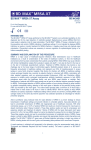
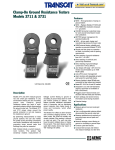
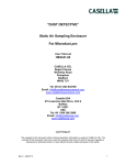
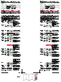
Introduction
Introduction
Display
plus CEL-6681 Dosimeter Microphone and Cable, or CEL-425 Microphone Adaptor.
The instruments in the CEL-320/360 Series consist of the instrument unit shown,
The instruments in the CEL-320/360 Series consist of the instrument unit shown,
Display
plus CEL-6681 Dosimeter Microphone and Cable, or CEL-425 Microphone Adaptor.
Battery Condition
Data is Being Recorded
Battery Condition
Data is Being Recorded
Under range has
Occurred
Measurement is Paused
Under range has
Occurred
Measurement is Paused
Frequency Weighting
Frequency Weighting
Overload has
Occurred
dB%
CA
REC
Measurement
Identity or Date
Overload has
Occurred
Indicates Active
Option Keys
Current Units
Current Mode,
Pressing the MENU
key will select each
of these in turn
SLM DATA
SET UP OPTION
dB%
CA
REC
Measurement
Identity or Date
Current Units
Current Mode,
Pressing the MENU
key will select each
of these in turn
Current Data
or Time
01043
Indicates Active
Option Keys
SLM DATA
SET UP OPTION
Current Data
or Time
01043
Preparation
Preparation
Connect a 9 V battery (6LF22) to the terminals in the battery compartment in the
Connect a 9 V battery (6LF22) to the terminals in the battery compartment in the
rear of the instrument. DO NOT disconnect the battery once runs have been stored;
rear of the instrument. DO NOT disconnect the battery once runs have been stored;
they will be lost.
they will be lost.
With the instrument switched OFF, insert the cable connector of the Dosimeter
With the instrument switched OFF, insert the cable connector of the Dosimeter
Microphone or the Microphone Adaptor into the socket in the top end of the case with
Microphone or the Microphone Adaptor into the socket in the top end of the case with
the red dot facing the front of the dosimeter.
the red dot facing the front of the dosimeter.
Field Accuracy Check
Field Accuracy Check
accuracy check (acoustic calibration) each time the instrument is switched ON and
accuracy check (acoustic calibration) each time the instrument is switched ON and
again at the end of measurement.
again at the end of measurement.
Operation of the instrument is achieved by a simple sequence of key strokes.
Operation of the instrument is achieved by a simple sequence of key strokes.
Use a CEL-282 (Class 2) or CEL-284/2 (Class 1) Calibrator to perform a field
Use a CEL-282 (Class 2) or CEL-284/2 (Class 1) Calibrator to perform a field
Fit the CEL-4725 Coupler (supplied with the calibrator) into the calibrator cavity,
Fit the CEL-4725 Coupler (supplied with the calibrator) into the calibrator cavity,
making sure it is firmly in contact with the shoulder in the cavity.
making sure it is firmly in contact with the shoulder in the cavity.
Fit the microphone into the coupler cavity, again making sure it makes contact
Fit the microphone into the coupler cavity, again making sure it makes contact
with the shoulder in the in the cavity.
with the shoulder in the in the cavity.
Switch the calibrator ON and proceed as follows.
Operation
Press
Display Shows
1. Switch
instrument
ON
DATA
2. Change
Mode
MENU
repeatedly
Switch the calibrator ON and proceed as follows.
Comments
Operation
Start Up messages showing
Instrument Type,
Serial number (if set),
Print (only when the print cable is
connected in place of a microphone),
Firmware Version,
finishing with last used
Operating Mode.
Select Option to allow Acoustic
Calibration.
The display shows the current SPL.
1. Switch
instrument
ON
Display Shows
2. Change
Mode
MENU
repeatedly
OPTION
3. Enable
Level
Change
and
are now enabled.
The display shows the current SPL.
and
are now enabled.
The display shows the current SPL.
OPTION
4. Change
Indicated
Level
(or
5. Set (Accept)
Calibration
Level
OPTION
4. Change
Indicated
Level
(or
5. Set (Accept)
Calibration
Level
Indicated level rises (falls) 0.05 dB for each key press.
Adjust to correct level for CEL-320/360 microphones at standard
) temperature and pressure = 113.6 dB.
The 113.6 dB calibration level is now
set, and will be stored by the
microphone assembly.
OPTION
Select Dose Measurement Set Up
1. Change
Operating
Mode
2. Select
another
Setup
A
MENU
sufficient
times
A
SET UP
1. Change
Operating
Mode
Select a set up from:
OSHA procedures Q = 5, Crit 90 dB,
A-wtd levels >80 dB and >90 dB,
MSHA procedures Q = 5, Crit 90 dB,
A-wtd levels >80 dB and >90 dB,
DOD procedures Q = 4,
2. Select
another
Setup
MENU
Sufficient
times
DATA
3. Then
REC
1. Change
Operating
Mode
When the run timer of a CEL-360 is
ON with beginning and End Times set,
the instrument waits counting back
the time remaining until the run starts.
When the run timer of a CEL-360 is
ON with Sync on, the instrument
DATA
REC
DATA
5. Inspect
Data from Current Run.
further data sufficient
Displays will be updated
from the
Current Run times
while the run is in progress.
6. If Required
Pause the run (II icon).
SET UP
Dose Measurement.
Dose data will be saved in the next
available data store.
MENU
Sufficient
times
DATA
2. Start Run
(Store Data)
DATA
waits until the clock is synchronised
with any selected profile time before
the run starts.
With a CEL-320 or when the run timer
of a CEL-360 is OFF, the instrument
waits for the next whole clock second,
then starts the run.
The REC icon indicates that the
instrument is now storing data in the
first available store.
Select a set up from:
OSHA procedures Q = 5, Crit 90 dB,
A-wtd levels >80 dB and >90 dB,
MSHA procedures Q = 5, Crit 90 dB,
A-wtd levels >80 dB and >90 dB,
DOD procedures Q = 4,
For further information on set Crit 85 dB, A-wtd levels >80 dB,
ups, consult the User Manual. NIOSH procedures Q = 3,
Crit 85 dB, A-wtd levels >80 dB,
ISO85 procedures Q = 3,
Crit 85 dB, A-wtd levels >70 dB,
ISO90 procedures Q = 3,
Crit 90 dB, A-wtd levels >70 dB,
Meter special procedure for logging
noise data as SLM.
A Loaded message shows that the
A
selected Setup is now active - for
example ISO procedure with 90 dB
Criterion.
3. Then
REC
DATA
4. Inspect
data from
the
Current Run
A
Measure Dose
Dose Measurement.
Dose data will be saved in the next
available data store.
The first display always shows the
currently loaded set up: for example
OSHA dose measurement.
SET UP
several
times
3. Load
Selected
Setup for
use
DATA
2. Start Run
(Store Data)
A
MENU
sufficient
times
SET UP
SET UP
Measure and Store Dose Data
1. Change
Operating
Mode
Select Dose Measurement Set Up
The first display always shows the
currently loaded set up: for example
OSHA dose measurement.
For further information on set Crit 85 dB, A-wtd levels >80 dB,
ups, consult the User Manual. ACGIH procedures Q = 3,
Crit 85 dB, A-wtd levels >80 dB,
ISO85 procedures Q = 3,
Crit 85 dB, A-wtd levels >70 dB,
ISO90 procedures Q = 3,
Crit 90 dB, A-wtd levels >70 dB,
special procedure for logging noise
data as SLM.
A Loaded message shows that the
A
selected Setup is now active: for
example ISO procedure with 90 dB
Criterion.
3. Load
Selected
Setup for
use
Indicated level rises (falls) 0.05 dB for each key press.
Adjust to correct level for CEL-420/460 microphones at standard
) temperature and pressure = 113.6 dB.
The 113.6 dB calibration level is now
set, and will be stored by the
microphone assembly.
OPTION
SET UP
several
times
Comments
Start Up messages showing
Instrument Type,
Serial number (if set),
Print (only when the print cable is
connected in place of a microphone),
Firmware Version,
finishing with last used
Operating Mode.
Select Option to allow Acoustic
Calibration.
The display shows the current SPL.
DATA
OPTION
3. Enable
Level
Change
Press
When the run timer of a CEL-360 is
ON with beginning and End Times set,
the instrument waits counting back
the time remaining until the run starts.
When the run timer of a CEL-360 is
ON with Sync on, the instrument
waits until the clock is synchronised
with any selected profile interval
before the run starts.
With a CEL-320 or when the run timer
of a CEL-360 is OFF, the instrument
waits for the next whole clock second,
then starts the run.
The REC icon indicates that the
instrument is now storing data in the
first available store.
DATA
The display shows where data from
the current run is being saved (store
4), and on a CEL-360 indicates the
number of completed profile periods
(3).
The display cycles through data from
the current run.
Some of the display screens offer
and
options that show
further parameters.
Press again to resume the run.
4. Inspect
data from
the
Current Run
REC
DATA
5. Inspect
Data from Current Run.
further data sufficient
Displays will be updated
from the
Current Run times
while the run is in progress.
6. If Required
Cut lines
8
40/4
L-4
CE
TO rs
IDE ete
GU el M
D
v
L
FIE nd Le
Sou
4 folds as shown
DATA
ive
tect t
Pro (do no
grill ove)
rem
2"
1, 1/ e
Typerophon
Mic
er
plifi
am
Pre
dot
Red
4"
2, 1/ e
Typerophon&
Mic
er
plifi
am
Pre
e
l th
Pul led
knur ve
slee to
ards e
outwase th r
to
le
re nnec
F
co
/OF
ON
or
igat
Nav keys
rt/
Sta /
se
Pautart
Res
ess
Acc ta
da
0
nge
Cha u
men
bles it
Enack ed
Qui
ht
k lig
Bac
U
MEN
A
DAT
p
Sto ds )
(nee nfirm
to co
9
0100
Pause the run (II icon).
The display shows where data from
the current run is being saved (store
4), and on a CEL-360 indicates the
number of completed profile periods
(3).
The display cycles through data from
the current run.
Some of the display screens offer
and
options that show
further parameters.
Press again to resume the run.
7. If Required
8. If Required
PLUS
Lock keys and display to
prevent unauthorised
tampering.
PLUS
Unlock keys and display to
restore normal operation.
9. Stop Run
The keys and display cannot be locked
while the instrument is paused.
7. If Required
8. If Required
Stop ?
This command must be confirmed.
9. Stop Run
The run is now ended.
DO NOT disconnect the battery once
runs have been stored; they will be
lost.
No operations possible.
10 Confirm
Stop
PLUS
Lock keys and display to
prevent unauthorised
tampering.
PLUS
Unlock keys and display to
restore normal operation.
Stop ?
This command must be confirmed.
DATA
DATA
10. Confirm
Stop
DATA
11. Switch OFF
The keys and display cannot be locked
while the instrument is paused.
Blank Screen
The run is now ended.
DO NOT disconnect the battery once
runs have been stored; they will be
lost.
No operations possible.
DATA
11. Switch OFF
Blank Screen
Recall Stored Dose Data
Recall Stored Dose Data
connect a Centronics printer via both C6671 PC Cable (supplied with the dosimeter)
connect a Centronics printer via both C6671 PC Cable (supplied with the dosimeter)
and CEL-6672 Printer Cable.
and CEL-6672 Printer Cable.
When a hard copy of stored dose data is required, BEFORE SWITCHING ON,
1. While not
logging data
When a hard copy of stored dose data is required, BEFORE SWITCHING ON,
Enable Data Recall and see the Start
Date & Time for the most recently
stored run.
1. While not
logging data
Select Start Date & Time for required
run.
If a printer is connected and switched
ON, continuing to press
will
eventually offer a PRINT ALL option
that is enabled by pressing
.
Shows where data for the selected
run is stored (Store 3) and on a
CEL-360, indicates the number of
completed profile periods.
2. Review
Stored
Runs
If a printer is connected and switched
ON, the next display shows PRINT
READY, if switched OFF, the display
shows PRINT OFF, otherwise the
DATA
Duration is displayed as in Step 6.
The display shows print messages while a data set from the selected
run is printed in standardised format for the measurement protocol
used.
4. Review
Stored
Data
DATA
Enable Data Recall and see the Start
Date & Time for the most recently
stored run.
DATA
DATA
2. Review
Stored
Runs
DATA
several
times
DATA
3. Review
Stored
Data
DATA
4. Review
Stored
Data
repeat
5. Print Hard
Copy
6. Review
Stored data
A
DATA
Operation as a Sound Level Meter
Display steps through all details and
parameters recorded for the run,
starting with duration and completes a
cycle back to Date & Time display for
the run.
Some displays offer
and
options that show further parameters.
Using the red dot to aid pin location, connect a CEL-425 SLM Microphone
Adaptor, perform an acoustic calibration as described above, then proceed as follows.
1. Start from
final Start
Up display
The last used measurement mode will
be selected.
DATA
3. Review
Stored
Data
DATA
If a printer is connected and switched
ON, the next display shows PRINT
READY, if switched OFF, the display
shows PRINT OFF, otherwise the
DATA
Duration is displayed as in Step 6.
The display shows print messages while a data set from the selected
run is printed in standardised format for the measurement protocol
used.
repeat
5. Print Hard
Copy
6. Review
Stored data
A
DATA
Operation as a Sound Level Meter
3. Review
SLM
Measurements
Using the red dot to aid pin location, connect a CEL-425 SLM Microphone
1. Start from
final Start
Up display
The last used measurement mode will
be selected.
DATA
A
dB
SLM
dB
several
times
SLM
4. Change
Settings
SLM measurement is now active with
the current A-weighted Fast level (LAF)
displayed.
SLM mode can be selected ONLY
while a microphone is fitted.
The display steps to Linear Peak (LLpk)
and then through all details and
parameters to Duration, before
completing the cycle back to the first
SLM display.
When
and
are shown on the display, the relevant navigator
keys may be used to change the current settings.
Blank Screen
No operations possible.
5. Switch OFF
Display steps through all details and
parameters recorded for the run,
starting with duration and completes a
cycle back to Date & Time display for
the run.
Some displays offer
and
options that show further parameters.
Adaptor, perform an acoustic calibration as described above, then proceed as follows.
DATA
2. If Required MENU
Change
sufficient
Mode
times
Select Start Date & Time for required
run.
If a printer is connected and switched
ON, continuing to press
will
eventually offer a PRINT ALL option
that is enabled by pressing
.
Shows where data for the selected
run is stored (Store 3) and on a
CEL-360, indicates the number of
completed profile periods.
several
times
Think environment Think Casella
2. If Required MENU
Change
sufficient
Mode
times
3. Review
SLM
Measurements
A
dB
SLM
dB
several
times
SLM
4. Change
Settings
SLM measurement is now active with
the current A-weighted Fast level (LAF)
displayed.
SLM mode can be selected ONLY
while a microphone is fitted.
The display steps to Linear Peak (LLpk)
and then through all details and
parameters to Duration, before
completing the cycle back to the first
SLM display.
When
and
are shown on the display, the relevant navigator
keys may be used to change the current settings.
Blank Screen
No operations possible.
5. Switch OFF
Think environment Think Casella
CEL-320/360 Dosimeters
060335 i1/Sept 01
CEL instrumentation and software is designed, manufactured and serviced by:
Casella CEL Limited,
Regent House, Wolseley Road, Kempston, Bedford, MK42 7JY, U.K
Phone: +44 (0) 1234 844 100 Fax: +44 (0) 1234 841 490 e-mail: [email protected]
Web: www.casella.co.uk
Casella CEL Inc,
Tech Park, 17 Old Nashua Road, Box 15, Amherst, NH 03031, U.S.A.
Office Phone: +1 603 672 0031 Toll Free: +1 800 366 2966 Fax: +1 603 672 8053
e-mail: [email protected].
DATA
01044
CEL-6681 Dosimeter
Microphone & Cable
CEL-425 Microphone
Adaptor
Red dot
Switches the
instrument ON/OFF
Changes menu
(operating mode)
Accesses stored data
Navigator keys select
active options from
current menu
Stops a measurement
but must be followed
immediately by
Confirms action of
other keys
Starts/Pauses/
Restarts a
measurement record
CEL-6681 Dosimeter
Microphone & Cable
CEL-425 Microphone
Adaptor
Red dot
Switches the
instrument ON/OFF
Changes menu
(operating mode)
Accesses stored data
Navigator keys select
active options from
current menu
FIELD GUIDE to CEL-320/360
Noise Dosimeters / SLMs
DATA
MENU
DATA
Stops a measurement
but must be followed
immediately by
Confirms action of
other keys
Starts/Pauses/
Restarts a
measurement record
FIELD GUIDE to CEL-320/360
Noise Dosimeters / SLMs
DATA
MENU
01044
CEL-320/360 Dosimeters
060335 i1/Sept 01
CEL instrumentation and software is designed, manufactured and serviced by:
Casella CEL Limited,
Regent House, Wolseley Road, Kempston, Bedford, MK42 7JY, U.K
Phone: +44 (0) 1234 844 100 Fax: +44 (0) 1234 841 490 e-mail: [email protected]
Web: www.casella.co.uk
Casella CEL Inc,
Tech Park, 17 Old Nashua Road, Box 15, Amherst, NH 03031, U.S.A.
Office Phone: +1 603 672 0031 Toll Free: +1 800 366 2966 Fax: +1 603 672 8053
e-mail: [email protected].