1
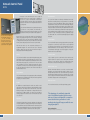
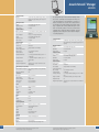
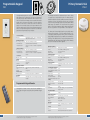
PRODUCT CATALOGUE
This catalogue provides information regarding
the Network components, paging and music
capabilities, distribution, client services,
installation and specifications.
LogiSon™ Acoustic Network
The LogiSon Acoustic Network is a revolutionary and multiple awardwinning sound masking, paging and music system. It combines an
unprecedented range of adjustment capabilities with the convenience of
centralized control and a streamlined design, establishing the standard
for performance, ease of use and aesthetics.
This catalogue provides information regarding the Network components,
paging and music capabilities, distribution, client services, installation
and specifications. If you require additional information about the
Network, please contact the LogiSon Representative for your area. Your
Representative can arrange a demonstration and provide you with other
useful resources pertaining to sound masking and acoustics.
To locate the Representative nearest you, visit our website:
www.logison.com
To contact the manufacturer:
K.R. Moeller Associates Ltd.
Toll Free (United States and Canada):
1-866-LOGISON or 1.866.564.4766
Tel: 905.332.1730
Fax: 905.332.8480
Email: [email protected]
Website: www.logison.com
This device complies with Part 15 of the FCC Rules. Operation is subject to the
following two conditions: (1) this device may not cause harmful interference and
(2) this device must accept any interference received, including interference that may
cause undesired operation.
Table of Contents
The High Performance Workplace
1
Network Overview
2
Network Components
Network Control Panel
Acoustic Network™ Manager
Programmable Keypad
Programmable Keypad Remote
Primary Network Hub
Primary Power Hub
Primary Accessory Hub
Secondary Network Hub
Loudspeaker Assembly
Ceiling Mount Adapter
Cable Assemblies
Cable Couplers
Audio Input Module
Relay Output Module
3
6
7
7
8
9
10
11
12
12
13
13
14
14
Paging & Music
15
Client Services
16
Installation
17
Specifications
19
The High Performance
Workplace
It is well known that uncontrolled noise and lack of speech privacy
negatively affect employees’ concentration, slowing task performance,
increasing errors and threatening the continuity of creative thought.
These acoustical problems can also impact their comfort, stress levels and
morale.
The “Quest for Silence”
Benefits include
•
•
•
•
•
•
•
•
Increased speech privacy
Reduced noise disruptions
Improved concentration
Increased productivity
Reduced project costs
Increased facility flexibility
Simultaneous paging & music
Quick return on investment
Clients include
A.C. Nielsen
Agilent Technologies
Capital One
CIBC
CNN
DaimlerChrysler
EDS
Ericsson
Ernst & Young
Fortis Bank
Goldman Sachs
Goodwill/Easter Seals
IBM
Kraft
Manulife Financial
Northwestern Mutual Life
Pentair Corporation
Philips
PricewaterhouseCoopers
Procter & Gamble
Rabobank
Royal Bank of Canada
Shell
Siemens
Smith Barney
Standard Life
Target
Telus
Time Warner
Towers Perrin
Volksbank
Xerox
1
When attempting to resolve these problems, noise control strategies are
often pursued in the “Quest for Silence” – the notion that good acoustics
are achieved when the sound levels in a space are as low as possible,
with zero being the best. However, just as with ergonomic factors such as
light, temperature and humidity, there is a comfort level for the volume of
sound – and it is not zero.
The noise floor is the level of continuous sound that characterizes a space
at any given time. If this floor is too high, the environment will be irritating
and tiring. If this floor is too low, conversations and noises can easily be
overheard, compromising both confidentiality and concentration. The
noise floor in offices is often so low that conversations are intelligible from
up to 50 feet (15.2 meters) away. Noticeable rises and falls in sound over
time and across these facilities make it even more difficult for employees
to ‘block out’ noise.
Achieving Acoustic Comfort®
Sound masking is part of a proactive approach to providing employees
with the productive space they need to excel. It is the only acoustic
treatment that can be used to properly control the noise floor, which
should generally range between 42 and 48 dBA.
Sound masking makes conversation and noise more difficult to hear
and comprehend, reducing distractions and providing confidentiality for
employees’ activities and conversations. It also reduces the variations in
the volume of sound over time and across the space, making the facility
appear quieter and movements from one area to another less disruptive.
Network Overview
In addition to the traditional benefits of sound masking outlined in the
introduction, the LogiSon Acoustic Network offers the following unique
features:
Multiple Control Options
A centrally-located Control Panel provides precise,
digital control over all settings for a single speaker, a group
of speakers or the entire Network. The ramp-up feature
increases acceptance in retrofit installations by gradually
increasing the masking volume over a defined period
of time, while the timer function allows the volume to
vary with activity levels during regular hours or holidays.
The priority page feature allows temporary settings to be
implemented in emergencies. The Panel also monitors
Network performance and security. Centralized control
of audio settings and software-based paging, keypad
and timer zones keep initial planning requirements low
and future flexibility high. The Network can be quickly
reconfigured without rewiring or accessing the ceiling.
Ethernet communication between a PC and Control
Panel enables adjustments using Acoustic Network™
Manager software and provides multiple-floor or entire
building control from one location.
Programmable Keypads and the accompanying
Remote provide on-demand audio control for private
offices and conference rooms.
Intelligent Technology
A single line of Cable carries power, control and
audio signals over the Network. The cable features
micro-connectors, enabling quick, accurate and tidy
installation.
The LogiSon™ Acoustic Network
The LogiSon Acoustic Network is a revolutionary sound masking, paging
and music system. Its networked technology ensures that you obtain the
best possible results with the speed, ease and versatility expected in the
digital age.
The Network has been installed in commercial, financial, government,
medical, institutional, educational, hospitality, military and judicial
environments, ranging in size from hundreds to millions of square feet.
Hubs are connected to the Control Panel in series.
These intelligent components allow the user to program
the output of the speakers. Micro-zoning (1 to 3 speakers
or 225 to 675 ft2, 21 to 63 m2), and fine, digital control
over frequency and volume adjustments provide greater
customization, effectiveness and comfort than traditional
masking systems. The Hubs also provide digital-quality,
multiplexed audio without the addition of sound generators,
amplifiers or equalizers. This high level of component
integration dramatically reduces the costs, energy and space
requirements typically needed for audio equipment.
Continuous Innovation
Our company is exclusively dedicated to developing innovative sound
masking system features to meet your needs and incorporated decades
of experience into developing the LogiSon Acoustic Network. We strive to
continuously increase the functionality of the Network. Recent advances
include enabling Ethernet connections, developing addressable Control
Panels, and adding Programmable Keypads, in addition to a host of other
new features.
A Speaker is connected to each hub and broadcasts
the masking sound and other audio signals over the
Network. Attractive enclosures and cable enable the
Network to be installed in visible applications.
The Ceiling Mount Adapter quickly converts the
speaker for downward-facing installation in hard ceilings.
Components are not shown to scale.
The Network can also be controlled using third party systems.
2
Network Control Panel
NCP-2
The Network Control Panel allows the user to program all
Network functions from a central location. Commands can
be sent to one, a group or all Primary Hubs on the Network.
The Primary Hub then controls the output of the Loudspeaker
attached to it and that of the Loudspeakers attached to the
Secondary Hubs.
The Control Panel is the Network’s only centralized component.
It provides the control, flexibility and functionality of
numerous rack-mounted components, reducing costs, energy
requirements and the space needed for audio equipment.
The Control Panel is the Network’s
only centralized component. It
provides the control
control, flexibility
flexibility and
functionality of numerous rackmounted components, reducing
costs, energy requirements and the
space needed for audio equipment.
Network settings, such as volume and equalizer levels for masking and
paging, timer, paging and keypad zones, timer schedules, and paging
channel selection can be easily and conveniently established, reviewed
or changed without entering the ceiling. The Network uses non-volatile
memory so that settings are preserved in the event of a power failure.
Timer Functions
The Control Panel features an advanced, calendar-based timer utility
that allows the masking settings to be programmed to accommodate
varying levels of office activity. Different masking volume schedules can
be established for each day of the week and for individual days during the
year when unique schedules may be required, such as holidays. Volume
changes are made at a user-defined rate, with gradual transitions between
events. There is also an introductory acclimatization or ramp-up feature for
retrofit installations, which gradually increases the masking volume over
a period of 15 days. The ramp-up period can be programmed to begin
on a defined date. The Control Panel automatically adjusts for daylight
saving time.
Priority Paging
Each Panel can control up to 125 components, including up to 25
Programmable Keypads. The Control Panels can also be networked
together so that the user can control up to 99 Panels from a single PC
using Acoustic Network™ Manager software.
The Control Panel also features a priority page input. When a priority signal
is relayed to the Control Panel, it sets the volume to a pre-programmed
level and plays the announcement over all Loudspeakers. The LogiSon
Network Administrator can set the masking to either continue to run or
to mute during the priority page. Once the priority page is complete, the
Network returns to its original settings.
Zoning
Security Features
The Control Panel enables the user to establish independent paging, timer
and keypad zones. Hubs are selected and assigned to a group (or zone),
which is then named and assigned unique characteristics. Each Control
Panel provides three paging zones, as well as an “off” zone, nine timer
zones, in addition to an “off” zone, and up to 25 keypad zones. There are
no restrictions on the size of these zones and they can be non-contiguous.
A single cable between the Network Control Panel and the hubs can
provide hundreds of zones.
A key is required to open the Control Panel’s enclosure and access the
keypad. A password is required to access and program the Network
settings. The Control Panel also features two integrated alarm relays,
which can be connected to warning lights, sirens or security systems.
Paging & Music
The Control Panel accepts up to three paging inputs, which are multiplexed
and distributed over the Network. Each Primary Hub can be programmed
to play any one of the three channels.
Ethernet Connection
Ethernet communication between a PC and the Control Panel enables
adjustments using Acoustic Network™ Manager software. The userfriendly software provides all of the Control Panel functions, as well as an
expanded range of adjustment options due to the ability of the PC’s large
screen to display more information simultaneously. The software can also
be utilized for diagnostic and record-keeping purposes.
Third Party Control
Volume
The Control Panel can also be controlled using third party systems.
No amplifiers are required between the audio source and the Control
Panel because each Primary Hub features an integrated amplifier. Volume
adjustments for each Primary Hub are made from the Control Panel.
Masking and paging volume adjustments are independent and can be
made in precise 0.5 dBA increments over a range of 35 to 85 dBA. The
masking or paging volume can also be set to zero in areas that only require
one or the other.
Equalization
The Network offers DSP-based, 1/3-octave equalization for masking and
1/1-octave equalization for paging at each Primary Hub. A wide range of
pre-set equalization profiles are available and can be modified as required.
Such fine-tuning capabilities allow the user to customize the masking curve
to suit the space, increasing the effectiveness of the masking sound.
3
“The advantages of centralized, networked
control of individual speakers, digital accuracy
and ease of future reconfiguration or expansion
ensure that this latest generation of sound
masking technology will keep pace with the everchanging workplace.”
Ericsson Canada Inc.
Manager of Facilities & General Services
4
Acoustic Network™ Manager
ANM2005
Control Performance
Functions
Masking Performance
Volume
Equalization (w/ PC)
Preset Contours
Paging Performance
Audio Input Modules
Zone Configuration
Volume
Equalization (w/ PC)
Preset Contours
Timer Performance
Number of Zones
Size of Zones
Timer Schedules
Volume Changes Per Day
Rate of Change
Volume Increments
Masking Acclimatization
Exception Schedules
Delayed-On Feature
Daylight Savings Adjustment
Control Panel setup, Network setup, masking,
paging, timer, keypad settings, audio inputs, and
diagnostics
35 to 85 dBA, 0.5 dBA steps, mute
1/3-octave, 23 bands
50 options
3, any combination of auxiliary, telephone and/or
microphone
Zone 1, 2, 3 or none (per Primary Hub)
35 to 85 dBA, 0.5 dBA steps, mute
1/1-octave, 8 bands
50 options
1 to 9
Unrestricted
Unique schedules for each weekday
9
0 to 9 minutes per increment
0.5 dBA steps
1 to 15 days, user-defined schedule, option of 0.5
or 1 dBA steps
3 user-defined exception schedules; up to 30
exception dates
Yes
Automatic; option of preset international or userdefined schedule
Network Size (Per Control Panel)
Max. # of Network Components
125, including a maximum of 25 Programmable
Keypads
Max. # of Loudspeakers
375
Connections
Power Input
3-pin, screw terminal
Network Output
6-pin
Ethernet Connection
10 Base-T RJ-45
Audio Inputs (3)
3-pin, screw terminal
Priority Page
2-pin, screw terminal
Power
Relay Outputs (2)
2-pin, screw terminal
Input
40 Vdc
Output
40 Vdc
Consumption
0.3 A Max or 12 W
Ground
Earth ground
Battery
Size
½ AA
Voltage
3.6 V
Life Expectancy
10 years
Physical Specifications
Dimensions (W x H x D)
28 x 23 x 7.6 cm; 11 x 9 x 3 inches
Enclosure Material
Steel with powdercoat finish
Color
Charcoal grey
Weight
5 lb; 2 kg
Keypad
20-key membrane panel
Display
4 x 20 backlit LCD
Mounting
Methods
4 keyhole mounting positions
Security
Physical
Key-lock enclosure
Electronic
Password required to access settings; 2 levels
5
A LogiSon Representative will design the Network and select the appropriate components.
All technical specifications are subject to change without notice.
A PC equipped with LogiSon™ Acoustic Network™ Manager Software
can be used to communicate with the Network when linked to the
Control Panel by Ethernet. The user has the ability to control up to 99
Network Control Panels from one location. The PC’s large screen allows
more information to be displayed simultaneously, permitting a greater
range of adjustment than is directly available through the Control
Panel. The user-friendly Software can be used to perform Network
configuration and to establish the masking, paging/music, timer and
keypad settings. These settings can be saved or printed for diagnostic
or record-keeping purposes.
Control Performance
Functions
Masking Performance
Volume
Equalization
Preset Contours
Paging Performance
Zone Configuration
Volume
Equalization
Preset Contours
Timer Performance
Number of Zones
Size of Zones
Timer Schedules
Volume Changes Per Day
Rate of Change
Volume Increments
Introductory Ramp Up
Exception Schedules
Delayed-On Feature
Daylight Savings Adjustment
Communication setup, Network setup, masking, paging,
timer, keypad settings, file management, diagnostics and
reporting.
35 to 85 dBA, 0.5 dBA steps, mute
1/3-octave, 23 bands
50 options
Zone 1, 2, 3 or mute (per Primary Hub)
35 to 85 dBA, 0.5 dBA steps, mute
1/1-octave, 8 bands
50 options
1 to 9
Unrestricted
Unique schedules for each weekday
9
0 to 9 minutes per increment
0.5 dBA steps
1 to 15 day user-defined schedule; option of 0.5 or 1 dBA
steps
3 user-defined schedules; up to 30 exception dates
Yes
Automatic; option of preset international or user-defined
schedule
A LogiSon Representative will design the Network and select the appropriate components.
All technical specifications are subject to change without notice.
6
Programmable Keypad
Primary Network Hub
PK-1
PNH-1
The Programmable Keypad can be used to adjust or mute the masking
and/or paging volume in a defined area of the LogiSon Acoustic Network.
Prior to this, the LogiSon Network Administrator will have used the Control
Panel or Acoustic Network™ Manager software to establish what area the
Keypad controls, what functions are available on it, and the amount by
which the user can increase or decrease the volume of the masking or
paging. For more information, please see the LogiSon™ Network Control
Panel User Manual and the LogiSon™ Acoustic Network™ Manger User
Manual. The Programmable Keypad can be installed in a standard singlegang wall box using a white, Decora-style faceplate.
Control Performance
Functions
Masking Performance
Volume Adjustment Range
Volume Restriction
Function Restriction
Paging Performance
Volume Adjustment Range
Volume Restriction
Function Restriction
Connections
Network Output
Zoning
Method
Zone Size
Physical Specifications
Dimensions (W x H x D)
Color
Weight
Remote Control
Remote Receiver
Mounting
Methods
Masking/paging volume control, masking/paging
mute, remote control receiver
-99 to +99 (0.5 dBA per increment)
User-defined maximum and minimum
User able to enable or disable the adjustment
function
-99 to +99 (0.5 dBA per increment)
User-defined maximum and minimum
User able to enable or disable the adjustment
function
6-pin
Electronically zoned using Network Control Panel (V
4.1 or later)
No limit
4 x 10.4 x 4.6 cm; 1.58 x 4.1 x 1.825 inches
White
120 g; 4.2 oz
IR remote control receiver for use with PKR-1
Single-gang wall box with white, Decora-style
faceplate
Programmable Keypad Remote
PKR-1
The Keypad also features a remote control receiver, enabling the
user to adjust the Keypad’s settings using the Programmable Keypad
Remote.
The Primary Network Hub is a sophisticated electronic device offering
a complete range of audio-related functions. The Primary Hubs are
installed throughout the ceiling in a grid-like pattern and a Loudspeaker
is attached to each one. These Hubs are connected to the Control Panel
in series and are automatically assigned an operating address during
initial start-up of the Network. The Control Panel uses this operating
address to identify and communicate with the Primary Hubs, allowing
the user to program all of the output variables of the Loudspeakers.
The Primary Hub features Digital Signal Processing (DSP) random
masking sound generation, a 1/3-octave masking equalizer, a 1/1octave paging equalizer, integrated volume controls for masking and
paging, multiplexed paging selection, an amplifier, and communication
technology. This sophisticated level of component integration provides
digital-quality audio and industry-leading flexibility, while eliminating
the need for centrally-located audio equipment.
Masking Performance
Masking Sound Generation
Volume
Equalization
Preset Contours
Paging Performance
Zone Configuration
Volume
Equalization
Preset Contours
Timer Performance
Programming
Secondary Hubs Supported
# of Secondaries Per Primary
# of Loudspeakers Per Primary
Connections
Network Input
Network Output
Secondary Hub Outputs
Loudspeaker Assembly Output
Cabling
Primary to Primary
Primary to Secondary
Power
Input
Consumption
Integrated Amplifier
Power
Physical Specifications
Dimensions (W x H)
Enclosure Material
Colour
Weight
Mounting
Methods
Security
Physical
Electronic
7
A LogiSon Representative will design the Network and select the appropriate components.
All technical specifications are subject to change without notice.
Digital Signal Processor (DSP)
35 to 85 dBA, 0.5 dBA steps, mute
1/3-octave, 23 bands
50 options
Zone 1, 2, 3 or none
35 to 85 dBA, 0.5 dBA steps, mute
1/1-octave, 8 bands
50 options
Programmed
Software
through
Control
Panel
or
0 to 2
1 to 3
6-pin
6-pin
2-pin (2)
2-pin
CA6 series cable
CA2 series cable
40 Vdc
At typical settings, 3.6 W; at maximum
settings, 6.4 W
5 Watts
13.0 x 4.5 cm; 5.1 x 1.75 inches
Plenum-rated resin
White or charcoal grey
0.2 kg; 0.4 lb
Flexible mounting options; see installation
manual
No physical controls on Hub
Monitored communication with Control Panel
A LogiSon Representative will design the Network and select the appropriate components.
All technical specifications are subject to change without notice.
8
Primary Power Hub
Primary Accessory Hub
PNH-1P
PNH-1A
The Primary Power Hub contains the same integrated components and
provides the same functions as the Primary Network Hub. In addition,
it features a power input used to provide the additional power required
for larger Networks. Plenum-rated, 2-conductor cabling should be
used to connect the Power Supply to the Power Hub and terminated
with the supplied connector.
Masking Performance
Masking Sound Generation
Volume
Equalization
Preset Contours
Paging Performance
Zone Configuration
Volume
Equalization
Preset Contours
Timer Performance
Programming
Secondary Hubs Supported
# of Secondaries Per Primary
# of Loudspeakers Per Primary
Connections
Power Input
Network Input
Network Output
Secondary Hub Outputs
Loudspeaker Assembly Output
Cabling
Primary to Primary
Primary to Secondary
Power
Input
Consumption
Integrated Amplifier
Power
Physical Specifications
Dimensions (W x H)
Enclosure Material
Colour
Weight
Mounting
Methods
Security
Physical
Electronic
9
Digital Signal Processor (DSP)
35 to 85 dBA, 0.5 dBA steps, mute
1/3-octave, 23 bands
50 options
Zone 1, 2, 3 or none
35 to 85 dBA, 0.5 dBA steps, mute
1/1-octave, 8 bands
50 options
Programmed through Control Panel or
Software
0 to 2
1 to 3
2-pin
6-pin
6-pin
2-pin (2)
2-pin
CA6 series cable
CA2 series cable
40 Vdc
At typical settings, 3.6 W; at maximum
settings, 6.4 W
5 Watts
13.0 x 4.5 cm; 5.1 x 1.75 inches
Plenum-rated resin
White or charcoal grey
0.2 kg; 0.4 lb
Flexible mounting options; see installation
manual
The Primary Accessory Hub contains the same integrated components
and provides the same functions as the Primary Network Hub. In
addition, it features an accessory input used to attach accessories,
such as the Programmable Keypad, to the Network.
Masking Performance
Masking Sound Generation
Volume
Equalization
Preset Contours
Paging Performance
Zone Configuration
Volume
Equalization
Preset Contours
Timer Performance
Programming
Secondary Hubs Supported
# of Secondaries Per Primary
# of Loudspeakers Per Primary
Connections
Accessory Connection
Network Input
Network Output
Secondary Hub Outputs
Loudspeaker Assembly Output
Cabling
Primary to Primary
Primary to Secondary
Power
Input
Consumption
Integrated Amplifier
Power
Physical Specifications
Dimensions (W x H)
Enclosure Material
Colour
Weight
Mounting
Methods
Security
Physical
Electronic
Digital Signal Processor (DSP)
35 to 85dBA, 0.5dBA steps, mute
1/3-octave, 23 bands
50 options
Zone 1, 2, 3 or none
35 to 85dBA, 0.5 dBA steps, mute
1/1-octave, 8 bands
50 options
Programmed through Control Panel or
Software
0 to 2
1 to 3
6-pin
6-pin
6-pin
2-pin (2)
2-pin
CA6 series cable
CA2 series cable
40 Vdc
At typical settings, 3.6 W; at maximum
settings, 6.4 W
5 Watts
13.0 x 4.5 cm; 5.1 x 1.75 inches
Plenum-rated resin
White or charcoal grey
0.2 kg; 0.4 lb
Flexible mounting options; see installation
manual
No physical controls on Hub
Monitored communication with Control
Panel
No physical controls on Hub
Monitored communication with Control
Panel
A LogiSon Representative will design the Network and select the appropriate components.
All technical specifications are subject to change without notice.
A LogiSon Representative will design the Network and select the appropriate components.
All technical specifications are subject to change without notice.
10
Secondary Network Hub
Loudspeaker Assembly
SNH-1P
LA-1
Secondary Hubs connect to a Primary Hub and a Loudspeaker is
attached to each one. The Secondary Hub’s output then duplicates
that of the Primary Hub to which it is attached.
Output Performance
Masking, Paging and Timer Settings
Loudspeakers Supported
# of Loudspeakers Per Secondary
Connections
Signal Input / Output
Loudspeaker Assembly Output
Cabling
Secondary to Primary
Secondary to Secondary
Power
Consumption
Physical Specifications
Dimensions (W x H)
Enclosure Material
Color
Weight
Mounting
Methods
Security
Physical
Inherited from Primary Hub
1
2-pin (2)
2-pin
CA2 series cable
CA2 series cable
0W
13.0 x 4.5 cm; 5.1 x 1.75 inches
Plenum-rated resin
White and charcoal grey
0.2 kg; 0.4 lb
Flexible mounting options; see installation
manual
No physical controls on Hub
A Loudspeaker Assembly is connected to each Hub and used to
broadcast the masking, paging and/or music. This component was
designed to provide significant flexibility. The same Loudspeaker
model is used with all Hubs. A threaded chain mount enables the
installer to reverse the Loudspeaker’s orientation – up or down – on
site. The custom clip allows the length of the chain suspending the
Loudspeaker to be adjusted without using tools. The cable retracts
into the enclosure to take up slack and ensure tidy installation. In open
ceilings, the chain can be replaced with an attractive braided steel
cable.
Audio Performance
Maximum Masking Output
Maximum Paging Output
Driver Specifications
Frequency Range
Dimension
Power Handling
Sensitivity
Magnet Structure
Impedance
Physical Specifications
Enclosure Type
Width
Height
Weight
Color
Connections
Loudspeaker Input
Cabling
Loudspeaker to Hub
Mounting
Methods
Chain Length
Chain Length Adjustment
Loudspeaker Orientation
Cable Management
87 dBA
87 dBA
90 to 10500 Hz
10.1 cm; 4 inches
25 W (RMS)
88.6 dBA / W / 1 m
510 g; 18 oz
16 Ohms
Sealed
16.5 cm; 6.5 inches
9.0 cm; 3.5 inches
0.95 kg; 1.9 lbs
White and charcoal grey
2-pin
Integrated cable assembly
Suspend from hub or from deck or bolt to hub (with
CMA-1)
51 cm; 20 inches
Tool-free chain clip
Upwards or downwards facing; tool-free reversibility
on site
Slack cable retracts into enclosure
Ceiling Mount Adapter
CMA-1
Mounting
Attachment to Loudspeaker
Cut Through Diameter
Suspension to Ceiling
Bolt Size for Suspension
Backup Suspension
Physical Specifications
Faceplate Diameter
Depth
Material
Color
Weight
11
A LogiSon Representative will design the Network and select the appropriate components.
All technical specifications are subject to change without notice.
Lay-in (with option for screw attachment)
17.2 cm; 6.8 inches
3-point suspension
8-32 x 2.5 inches
Additional suspension option from d-ring on Hub
22.0 cm; 8.7 inches
2.8 cm; 1.1 inches
Plenum-rated resin
White
0.1 kg; 0.2 lb
A LogiSon Representative will design the Network and select the appropriate components.
All technical specifications are subject to change without notice.
The Ceiling Mount Adapter
is used to quickly convert the
Loudspeaker for downward-facing
installation in gypsum or other
hard ceilings. The Hub is mounted
directly on the Loudspeaker and
this configuration is then lowered
into the Adapter once it has been
mounted to the ceiling. A steel
back plate offers support.
12
Cable Assemblies
Audio Input Modules
CA2-5, CA2-18, CA2-25
CA6-5, CA6-18, CA6-25, CA6-50, CA6-100
Cable Assemblies connect the components, carrying power, control
and audio signals over the Network. The plenum-rated 2-conductor
cables are available in standard 5-, 18- and 25-foot (1.5-, 5.5- and
7.6-meter) lengths. The plenum-rated 6-conductor cables are available
in standard 5-, 18-, 25-, 50-, and 100-foot (1.5-, 5.5-, 7.6-, 15.2-,
and 30.4-meter) lengths. Cable Couplers are used to combine the
cables when longer lengths are required. All Cable Assemblies feature
custom over-molded micro-connectors with positive lock devices and
orientation guides, enabling quick, accurate and tidy installation.
Physical Specifications
Lengths
5 ft, 1.5 m; 18 ft, 5.5 m; 25 ft, 7.6 m; 50 ft, 15.2 m;
100 ft, 30.4 m
Connectors
6- and 2-pin over-molded micro-connectors
Gauge
20 AWG
Material
Copper stranded
Color
White and charcoal grey
Safeguards
Physical
Orientation guides and positive-locking mechanism
Cable Couplers
CC2, CC6, PC2
Cable Couplers (CC2 and CC6) are used to connect two Cable
Assemblies together to offer a longer cable run. They are available
in 2- and 6-conductor sizes and feature micro-connectors, permitting
quick connections between cables.
If the paging, timer or keypad functions are not needed, the Control
Panel can be removed after the user configures the Network. In this
case, a Power Coupler (PC2) is used to provide power to the Network.
The Power Coupler connects the output from the Power Supply to the
cable running to the Hubs.
AIM-2A, AIM-2M, AIM-2T
The Audio Input Modules are used to connect paging and/or music
sources to the Control Panel. The Modules offer analog to digital
conversation and automatically adjust for input sensitivity. Each
Control Panel accepts any combination of three inputs: auxiliary,
microphone and telephone.
Auxiliary
Input impedance
Input maximum level
Input sensitivity for maximum output
Gain
Frequency response
Microphone
Input impedance
Input maximum level
Input sensitivity for maximum output
Gain
Frequency response
Telephone
Input impedance
Input maximum level
Input sensitivity for maximum output
Gain
Frequency response
100 kohm
10 V
300 mV
Max. 20 dB, adjustable in 32 1 dB steps
20 to 10000 Hz
600 ohm
30 mV
1 mV
Max. 70 dB, adjustable in 32 1 dB steps
20 to 10000 Hz
600 ohm
10 V
300 mV
Max. 20 dB, adjustable in 32 1 dB steps
20 to 10000 Hz
Relay Output Module
ROM-2
The Relay Output Module is used to connect the Control Panel to
up to two external devices, such as warning lights, sirens or security
systems.
Relay Output
Rated load
0.5 A at 125 VAC; 1 A at 24 VDC
Physical Specifications
Connectors
6- and 2-pin over-molded micro-connectors
Color
White and charcoal grey
Safeguards
Physical
Orientation guides and positive-locking mechanism
13
A LogiSon Representative will design the Network and select the appropriate components.
All technical specifications are subject to change without notice.
A LogiSon Representative will design the Network and select the appropriate components.
All technical specifications are subject to change without notice.
14
Client Services
Paging & Music
Keypad
ypad Control
A Programmable Keypad can also
be used to adjust or mute the
paging volume in a defined area
of the LogiSon Acoustic Network.
Prior to this, the LogiSon Network
Administrator will have used the
Control Panel or Acoustic Network
Manager Software to establish what
area the Keypad controls, what
functions are available on it, and
the amount by which the user can
increase or decrease the volume of
the paging.
Overview
Site Inspection
Each Control Panel accepts up to three line-level audio inputs, which it
multiplexes and distributes over the Network. Sources can include any
combination of microphones, music sources and telephone system
inputs. When required, mixers can be used to combine signals before
they are relayed to the Control Panel.
Your Representative can visit your facility to ensure the conditions
required by the Network are in place and provide you with the
opportunity to ask questions and better familiarize yourself with the
functions and benefits of the Network. At this time, your paging and/
or music requirements can also be reviewed.
Paging zones are software-generated rather than hardwired. Each
Primary Hub is programmed to broadcast one of the three channels
in areas where paging or music is required. The Control Panel or PC
is used to manage these zones, as well as the volume and equalizer
settings.
Network Design
A Programmable Keypad can be used to adjust or mute the paging
volume in a defined area of the LogiSon Acoustic Network. Prior to this,
the LogiSon Network Administrator will have used the Control Panel
or Acoustic Network Manager Software to establish what area the
Keypad controls, what functions are available on it, and the amount
by which the user can increase or decrease the volume of the paging.
High Quality Audio
The LogiSon Acoustic Network provides digital-quality audio. The 25watt RMS, high sensitivity driver has a wide, flat frequency response
and clean audio output of up to 85 dBA. The high density of masking
speakers ensures there is a uniform distribution of sound.
Minimal Equipment Requirements
The Control Panel is the Network’s only centralized component. It
provides the control and functionality of numerous rack-mounted
audio components, reducing costs, energy requirements and the space
typically needed for such equipment. Furthermore, no independent
amplifiers or equalizers are required because these components have
been integrated into each Primary Hub. Volume adjustments can be
made in precise 0.5 dBA increments over a range of 35 to 85 dBA.
Each Primary Hub includes a 1/1-octave equalizer for paging output.
The paging volume and equalization settings are independent of the
masking settings.
To properly design the Network, your Representative requires blueprints
or CAD files of 1) the reflected ceiling plan, 2) the furniture layout
and 3) the partition plan, including a legend showing deck-to-deck
wall construction or any other plenum obstructions. Upon provision of
these blueprints and other basic information, your Representative will
plan the installation of the LogiSon Network. Your Representative will
also consult contractors, designers, telephone companies, and other
trades as required.
Quotation
After planning the Network design, your Representative will provide
you with a quotation.
Success demands more than just the
right product. It requires the expertise
of a group of individuals who are
dedicated to the proper design
and implementation of your sound
masking system and can provide
you with ongoing service as your
organization grows and changes.
Our international representatives
bring expertise from numerous
facility-related fields and pride
themselves on their commitment
to customer satisfaction.
Installation
Network design and component selection are performed by your
LogiSon Representative; however, installation can be handled by
the Representative’s in-house technicians, by third-party installation
companies, or by your own electrical or audio contractor.
Configuration
To ensure maximum performance of the Network, your Representative
will perform the Network configuration either independently or in
conjunction with your acoustical consultant. Configuration includes
tuning the masking sound, programming timer, keypad and paging
zones, timer functions, paging channel selection, volume and equalizer
settings.
Maintenance
Priority Page Feature
The Control Panel features a priority page input. When a priority signal
is relayed over this line, the Control Panel sets the paging volume
to a pre-programmed level and plays the announcement over all
Loudspeakers. The Network Administrator can set the masking to
either continue to run or to mute during the priority page. Once the
priority page is complete, the Network returns to its original settings.
Overview
After installation, your Representative will follow up with you to ensure
your satisfaction with the Network’s performance. To ensure the
Network operates effectively throughout its lifecycle, we encourage
you to maintain contact with your Representative. The Representative
can determine if any office changes have been implemented that
necessitate retuning the masking sound or other reconfiguration.
“They did an excellent
job in all aspects of
the project. They kept
in steady contact,
worked well with the
construction company,
stayed on budget,
and presented no
surprises. I would
definitely recommend
them for any sound
masking or related
work.”
Director of Facilities
Monster
Relocation
Quick, Easy Changes
All Network settings are handled digitally. There is no need to rewire
the Network or access the ceiling in order to rezone or reconfigure the
audio settings, permitting fast and inexpensive changes as required.
15
If you move, your Representative can remove the Network from your
current location and install it in your new premises. If necessary, it can
easily be expanded.
16
Installation
A Typical Installation
The Hubs are typically installed
in a grid-like pattern above the
suspended ceiling and a Loudspeaker
is attached to each Hub. Primary
Hubs are connected to the Control
Panel in series. Secondary Hubs
branch from one Primary Hub or are
connected to the Primary Hub in
series. The Network can be installed
without hard-wiring precise timer or
paging zones, because all zones are
software-generated.
Overview
Complement the Facility’s Appearance
The Network can be installed in new or retrofit, open and/or closed
plan spaces of any size. Installation can be handled by your LogiSon
Representative’s in-house technicians, by third party companies,
or by your own electrical or audio contractor. To ensure maximum
performance of the Network, your Representative will perform the
Network configuration independently or in conjunction with your
acoustical consultant.
Though the Network is typically installed above the suspended ceiling,
it has been designed for visible applications. Modern Loudspeaker
enclosures, micro-connectors and fitted Ceiling Mount Adapters
complement the investment you make in your facility’s professional
appearance.
The Hubs are typically installed in a grid-like pattern above the
suspended ceiling and a Loudspeaker is attached to each Hub. Primary
Hubs are connected to the Control Panel in series. Secondary Hubs are
connected to a Primary Hub. The Network can be installed without
hard-wiring precise paging, timer or keypad zones, because all zones
are software-generated.
For additional information, please refer to the LogiSon™ Acoustic
Network™ Installation Manual.
Hub Connections & Icons
If timer and paging and/or music functions are required, the Control
Panel can be installed in any specified location. If these functions are not
needed, the Control Panel can be removed after your Representative
configures the Network. If changes or additions need to be made at a
later date, a Control Panel can be reconnected to the Network.
If you move, your Representative can remove the Network from your
current location and install it in your new premises. If necessary, it can
easily be expanded.
Plenum Installation
Installation is exceptionally efficient because LogiSon components
were designed to:
Ensure Accuracy
All cabling connections are clearly marked with embossed icons on the
Hubs. The Cable Assemblies feature micro-connectors with positive lock
devices and orientation guides that prevent improper connections.
Provide On-Site Flexibility
If timer and paging and/or music
functions are required, the Control
Panel can be installed in any specified
location. If these functions are not
needed, the Control Panel can be
removed after your Representative
configures the Network. If changes
or additions need to be made at a
later date, a Control Panel can be
reconnected to the Network.
Loudspeakers can be modified on site to accommodate various
installation requirements. The threaded chain mount and flexible
enclosure design allow the Loudspeaker to be suspended from the Hub
in either upward or downward orientation. The Hub, Loudspeaker and
Ceiling Mount Adapter can be quickly attached for downward-facing
installation in gypsum or other hard surface ceilings. Hubs can also be
installed in a variety of ways, including bolted to the deck, suspended
from the deck or suspended from other approved structures within the
ceiling. There is also a backup suspension option.
Cut-Through Installation
Deck
Minimize the Number of Required Tools
The Cable Assemblies and Cable Couplers feature micro-connectors
that simply snap together. Disconnecting the Cable Assemblies from
the Hubs only requires disengaging the locking mechanism. The custom
clip allows the length of the chain suspending the Loudspeaker to be
adjusted without using tools.
17
Ceiling
Cut Through Diameter
17.2 cm (6.8 inches)
18
Specifications
F.
FCC – EN 55103-1&2 – Audio, Video and Entertainment Lighting Control
1.4. PERFORMANCE REQUIREMENTS
A.
MASTERFORMAT™ 2004 EDITION SECTIONS
27 51 19 – SOUND MASKING SYSTEMS
27 51 13 – PAGING SYSTEMS
PREVIOUS MASTERFORMAT™ SECTION
16820 – SOUND REINFORCEMENT / SOUND MASKING SYSTEMS
General Performance
1.
2.
B.
Sound Masking Performance
1.
NOTE TO SPECIFIER
LogiSon™ Acoustic Network – Networked sound masking, paging and music system.
2.
3.
This section is based on the products manufactured by K.R. Moeller Associates Ltd., located at:
4.
3-1050 Pachino Court
Burlington, Ontario
L7L 6B9
Canada
Toll Free
Tel
Fax
Email
Web
1-866-564-4766
(905) 332-1730
(905) 332-8480
[email protected]
www.logison.com
5.
6.
C.
2.
K.R. Moeller Associates Ltd. also manufactures the Scamp® and AccuMask™ Sound Masking Systems.
(Spec Version 2.0)
3.
4.
1. PART ONE – GENERAL
5.
A.
B.
6.
Sound masking systems
Paging systems
The system shall use digital signal processing (DSP) technology for masking sound
generation and adjustment of masking and paging signals.
The masking sound shall be random and provide no noticeable repetitive pattern.
The primary network devices shall provide a 1/3 of an octave equalizer for the masking
signal, capable of equalizing zones of 1 to no more than 3 speakers.
The masking volume shall be digitally adjustable in 0.5 dBA increments at each primary
network device (controlling 1 to no more than 3 speakers) over a range of 35 dBA to
85 dBA @ 1m.
The system shall be capable of muting the masking volume at each primary network
device.
After adjustment, the system shall provide a spatial uniformity of +-½dBA for the
masking volume with furnishings in place.
Paging Performance
1.
1.1. SECTION INCLUDES
The sound masking and paging system shall be entirely centrally controllable from a
control panel and / or an attached computer (including over multiple floors).
The system shall be able to automatically assign an address to individual network
components.
7.
8.
The primary network devices shall provide a 1/1-octave equalizer for the paging signal,
capable of equalizing zones of 1 to no more than 3 speakers.
The paging volume shall be digitally adjustable in 0.5 dBA increments at each primary
network device (controlling 1 to no more than 3 speakers) over a range of 35 dBA to
85 dBA @ 1m.
The system shall carry three digital multiplexed paging channels.
The network control panel shall accept up to three audio input modules with any
combination of auxiliary, telephone or microphone inputs.
The system shall be able to assign one of the three paging channels to each primary
network device.
The system shall be able to change the paging channel assigned to a primary network
device without rewiring.
The system shall be capable of muting the paging signal at each primary network
device.
The system shall provide a priority paging override of existing paging settings.
1.2. RELATED SECTIONS
D.
A.
B.
27 51 19 – Sound Masking Systems
27 51 13 – Paging Systems
1.3. REFERENCES
A.
B.
C.
D.
E.
19
UL6500 – Standard for Audio/Video and Musical Instrument Apparatus for Household,
Commercial and Similar General Use
UL 2043 – Standard for Fire Test for Heat and Visible Smoke Release for Discrete Products and
Their Accessories Installed in Air-Handling Spaces; 1996
ASTM E 1374-02 – Standard Guide for Open Office Acoustics and Applicable ASTM
Standards
ASTM E 1573-02 – Standard Test Method for Evaluating Masking Sound in Open Office
Using A-Weighted and One-Third Octave Band Sound Pressure Levels
ASTM E 1130-02e1 – Standard Test Method for Objective Measurement of Speech Privacy in
Open Offices Using Articulation Index
Timer Performance
1.
2.
3.
4.
5.
6.
7.
8.
The system shall provide a timer function allowing masking volume levels to be
automatically adjusted according to a programmed schedule.
The system shall provide a calendar-based programmable timer function. Timer
schedules shall be assigned to an individual or group of primary network devices.
The system shall provide automatic daylight saving time adjustments.
The system shall provide an acclimatization process that automatically increases the
masking volume over a period of time according to a programmed schedule. The
system should allow for independent acclimatization schedules for each timer zone.
The system shall allow for up to nine independent timer zones per control panel/
programmable timer.
The system shall allow independent timer schedules for each day of the week.
The system shall allow variable rates of volume adjustment.
The system shall provide optional exception timer schedules for calendar days requiring
a different schedule from the norm.
20
9.
E.
The system shall offer a programmed system activation date.
1.7. DELIVERY, STORAGE AND HANDLING
In-Room Occupant Control
1.
2.
3.
4.
5.
6.
A.
B.
The system shall capable of including wall mounted, in-room programmable keypads
giving the facility occupants manual control over the masking and paging volumes
The keypads shall be capable of adjusting masking and paging volumes
independently.
The keypads shall be capable of restricting access to masking and/or paging volume
control.
The keypads shall be capable of restricting the range of allowable volume adjustment
for masking and paging independently.
The keypads shall be capable of individually muting the masking and paging output.
The keypads shall provide an infrared remote control receiver.
C.
D.
1.8. WARRANTY AND MAINTENANCE
A.
2.
F.
Protect from moisture during shipping, storage and handling.
Deliver in manufacturer’s original unopened and undamaged packages with manufacturer’s
labels legible and intact.
Inspect manufacturer’s packages upon receipt.
Handle packages carefully.
Provide a written warranty that products installed shall be free from defects in parts or
assembly for a 5-year period from date of first use (the date of network initialization)
PART TWO – PRODUCTS
Diagnostic Performance
2.1. MANUFACTURERS
1.
2.
G.
Reporting Performance
1.
2.
H.
The system shall be capable of ensuring that the expected number of primary network
devices is present and communicating properly with the network control panel.
The system shall be capable of identifying the primary network devices that are not
communicating properly over the network.
The network control panel shall be capable of reading and displaying the current
settings for all primary network devices.
The system shall be capable of generating detailed reports of all system settings down
to the level of individual primary network devices.
Security Performance
1.
2.
3.
4.
5.
The network control panel shall be contained in a locked metal enclosure.
Access to the control panel functions shall be password protected.
No physical controls shall be located on the system loudspeakers or primary network
devices.
The system shall allow for all settings to be backed up on an electronic storage
medium
The system shall monitor performance at each network component.
A.
B.
C.
2.2. NETWORK COMPONENTS
General System Overview: The sound masking and paging system shall be a networked decentralized
system with complete digital, central control down to individually addressable speakers. The system
shall be comprised of a selection of a) distributed primary network devices; b) distributed secondary
network devices; c) loudspeaker assemblies; d) one or more network control panels; e) pc network
control software; f) programmable keypads; g) cable assemblies h) audio input modules; i) ceiling
mount adaptors and j) one or more power supplies.
A.
C.
Each primary network device shall provide:
1.
2.
3.
4.
5.
6.
7.
8.
9.
1.5. SUBMITTALS
A.
B.
Acceptable Manufacturer: K.R. Moeller Associates Ltd.; 3-1050 Pachino Court, Burlington,
Ontario L7L 6B9 Canada. Toll Free: 866 LOGISON (1-866-564-4766). Tel: (905) 847-8633.
Fax: (905) 847-7709. Email: [email protected]. Web: www.logison.com.
Substitutions: Not permitted.
Requests for substitutions will be considered provided that the all performance requirements
in Section 1.4 of this specification are met. Other manufacturers seeking approval must
provide a signed compliance statement from an executive officer of the manufacturer.
Product Data: Manufacturer’s specifications and installation instructions
Network Design: Schematics of the network showing quantity and location of network
components and related cabling and accessories
Warranty Documents: Warranty documents covering the network components.
A DSP-based masking sound generator
An individual 1/3 of an octave, 23-band equalizer for masking
An individual 1/1 octave, 8-band equalizer for paging
An individual volume control for masking
An individual volume control for paging
Network communication components
A paging channel selector and demultiplexer
An audio amplifier
Overall dimensions of:
1.6. QUALITY ASSURANCE
A.
B.
C.
D.
E.
21
Manufacturer Qualifications: Minimum of 10 years manufacturing sound masking systems.
Network Design – Performed by an approved manufacturer representative.
Installer Qualifications – Approved by manufacturer representative and are trained with the
specified products or have demonstrated experience with the installation of similar products
to those specified.
Network Adjustment – Done by an approved manufacturer representative or trained
contractor
Single Source Responsibility – Source Network Control Panels, Primary and Secondary
Network Devices, Loudspeaker Assemblies, Programmable Keypads and Cable Assemblies
from a single manufacturer.
i.
ii.
B.
Diameter
Height
5.1 inches; 13.0 cm
1.75 inches; 4.5 cm
Each secondary network device shall provide:
1.
2.
3.
A loudspeaker connection
Signal connections to/from other primary/secondary devices
Overall dimensions of:
i.
ii.
Diameter
Height
5.1 inches; 13.0 cm
1.75 inches; 4.5 cm
22
C.
Each loudspeaker assembly shall provide:
1.
2.
1.
2.
A connection to the network devices
A suspension chain at least 20 inches (51 cm) in length and tool-less length adjustment
clip
An acoustically damped enclosure
Tool-less, on-site adjustment of upward / downward loudspeaker orientation
Overall dimensions of:
3.
4.
5.
H.
6.
Diameter
Power Rating
Sensitivity
Frequency Response
Impedance
Magnet Structure Weight
4.0 inches; 10.0 cm
25 Watts RMS
87 dBA @ 1W / 1m
100 - 10,000 Hz (+/- 6 dB)
16 Ohms
17.6 oz; 500 g
i. Height
ii. Width
iii. Depth
9.4 inches; 23.8 cm
11.0 inches; 28.0 cm
3.2 inches; 8.0 cm
Power the network devices and control panels
PART THREE - EXECUTION
3.1. NETWORK DESIGN
A.
Network communication components
Network control electronics for masking, paging and timer functions
Connections for audio input modules
Paging multiplexing circuitry
Connections to network devices, additional control panels and a computer
Ethernet connection and IP addressability
Overall dimensions of:
Attach on-site to convert plenum loudspeakers to ceiling plate loudspeakers
Power Supplies to:
1.
3.
Audio input for microphone, telephone or auxiliary audio sources
Level adjustment controls
Ceiling Mount Adaptors to:
1.
J.
Each network control panel shall provide:
1.
2.
3.
4.
5.
6.
7.
E.
6.5 inches; 16.5 cm
3.5 inches; 9.0 cm
A loudspeaker driver with:
i.
ii.
iii.
iv.
v.
vi.
D.
Diameter
Height
Audio Input Modules to provide:
1.
2.
I.
i.
ii.
Provide power, audio and control signals over a single cable assembly
Provide overmolded micro-connectors
Design network according to manufacturer’s specifications.
3.2. EXAMINATION
A.
B.
C.
D.
E.
F.
Ensure that facility build out is at a stage suitable for the system installation.
Ensure that facility is constructed according to plans including wall locations, ceiling types
and plenum barriers.
Ensure that the plenum height is appropriate as per manufacturer’s recommendations and as
per plan.
Ensure power requirements have been provided as per plan.
Ensure sufficient space for centrally located components is available as per plan and
manufacturer’s specifications.
Ensure any third-party components required to be interfaced with the network have been
provided.
The PC network control software to:
3.3. PERMITS
1.
Allow control of all system adjustments from a computer, including:
A.
i.
ii.
iii.
iv.
v.
vi.
2.
3.
F.
4.
5.
23
Allow the reporting of all system settings
Perform network diagnostics
Programmable Keypads shall provide:
1.
2.
3.
G.
Network setup
Sound masking volume and equalization
Paging volume and equalization
Sound masking timer programs
Paging zoning
Programmable Keypad setup
Network communication components
A display indicating function selection and volume adjustments
A keypad interface for controlling all functions (masking/paging selection, volume
increase/decrease, mute)
An infrared remote control receiver
An enclosure capable of being installed in a single gang box
Cable assemblies to:
Obtain necessary permits for installation work.
3.4. INSTALLATION
A.
B.
C.
D.
E.
Follow all applicable codes for the area
Follow manufacturer’s recommendations regarding installation as found in the LogiSon
Acoustic Network Installation Manual
Follow the system design for location of loudspeakers and wiring
Record any necessary changes to the system design on the plan
Ensure that supplementary materials used meet applicable safety standards
3.5. FIELD QUALITY CONTROL
A.
B.
C.
D.
E.
F.
Ensure that plenum heights meet the minimum recommended by the manufacturer for the
loudspeakers
Ensure that distance between the top of the loudspeaker and the deck meets manufacturer’s
minimum specifications
Ensure that loudspeakers are suspended in a level manner
Ensure that loudspeakers are not obstructed as much as possible
Ensure cables are properly supported in the ceiling
Ensure cables are securely terminated
24
3.6. NETWORK CONFIGURATION AND ADJUSTMENT
A.
Follow manufacturer’s recommendations for system settings as found in the LogiSon User
Manual
3.7. CLEANING
A.
B.
C.
Ensure that empty packaging is removed.
Ensure that any material waste is removed
Ensure the product is clean and presentable where required
3.8. DEMONSTRATION AND TRAINING
A.
B.
C.
Demonstrate operational system to customer by walking the space
Demonstrate functionality of the system to the customer or customer’s representative
Train customer employee to maintain system as required
3.9. TESTING AND REPORTING
A.
B.
C.
D.
25
Test area for consistency of masking volume and quality
Verify that paging zoning and levels are appropriate and as per plan
Test masking volumes with mechanicals off and with space unoccupied
Provide a printed report detailing system settings
Acoustic Control at Your Fingertips™
[email protected]
www.logison.com
1.866.LOGISON
Patents pending in U.S., Canada and other jurisdictions.
© 2006 K.R. Moeller Associates Ltd. Scamp and Archoustics are registered trademarks of 777388 Ontario Limited.
LogiSon and Acoustic Network are trademarks of 777388 Ontario Limited.